

d
S
ill
39759 USA
HAM IV / HAM IVX
Co
0
,
k
308 Industrial Park Roa
tarkv
Ph: (662) 323-9538 FAX: (662) 323-6551
e, MS
INSTRUCTION MANUAL
GENERAL DESCRIPTION
The HAM IV rotator consists of a bell type
rotator, a metered control unit and the necessary
mounting hardware. The stock HAM IV is
intended for in-tower mounting on the base plate
which is part of the tower. However, in some
instances, mast mounting is desired. The Lower
Mast Support Kit, PN 51467 10, contains a lower
mast support and the necessary hardware to
facilitate mounting the HAM IV Rotator on top
of a mast.
New features in the HAM IV include an 8 pin
Cinch connector on the rear panel of the control,
a chassis ground connection on the 110 VAC
model, and a locking CinchTM connector at the
rotor unit.
CAUTION
When using the lower mast support, antenna
size is restricted to 7.5 square feet of wind
surface area
Cinch'm a Division of Labinal Components & Systems
HAM IV has 110 VAC
ntroller HAM IVX has 22
The rotator unit must be wired to the control unit
with an 8-wire cable. The control unit must be
placed inside the house or other protected
location. Included in the shipping box are:
A. Instruction Manual
B. Rotator Unit
C. Controller Unit
D. Mounting Hardware Pac
E. Connector Parts Pack
Due to the wide variet y of towers availabl e, each
installation will have different requirements. The
gauge of the 8-wire cable to connect the control
unit to the rotator depends upon the distance
between the rotator and control. The longer the
distance, the larger the diameter of the wire
required. Various antennas or beams require
different installation methods.
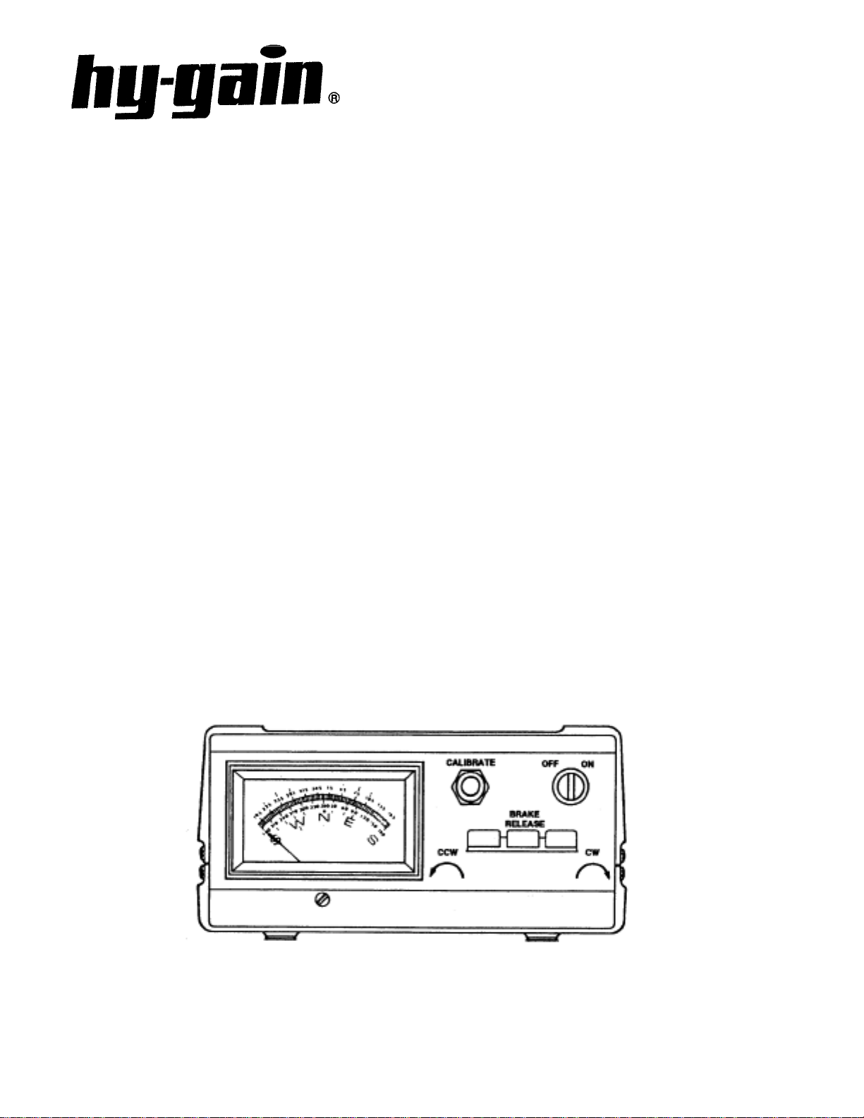
Figure 1
Control Unit - Front Panel
Specifications
Input Voltage 120 VAC 50/60 Hz
Optional 220 VAC 50/60 Hz
Motor 24 VAC 2.25 Amp, capacitor start, capacitor run
Brake Solenoid 24 VAC, 5.0 Amps
Power Transformer 120 VAC/26 VAC 10% duty, thermal switch protected
Optional 220 VAC/26 VAC 10% duty, thermal switch protected
Meter Transformer 120 VAC/23 VAC continuous duty
Optional 220 VAC/23 VAC continuous duty
Meter DC voltmeter 1000 ohms/volts, 1 MA full scale
Meter Scale Direct Reading: North centered, 5 degree increments
Optional Direct Reading: South centered, 5 degree increments
Maximum Ante nna Si ze :
A. Tower Mounted as per Figure 3 15 sq. ft. (1.4 sq. m) of wind surface area
B. Outside Tower or mast Mounted as per Fig. 5 or 6 7.5 sq. ft. (0.7 sq. m) of wind surface area
*Maximum Effective Moment (EM) 2,800 ft. lb. (387 Kg. M)
Operational Temperature Range -30 deg. F to 210 deg. F (-34 deg. to 99 deg. C)
Maximum Int erconnect Ca ble Resistance:
A. Terminals 1 and 2 .8 ohm
B. Terminals 3,4,5,6,7, and 8 2.0 ohms
Rotation Time 45-60 seconds with 60 Hz input
Brake Positive, electrically operated wedge, 75 segments
spaced 4.8 degrees apart
Rotator Size 8 in. (20 cm) max. diameter by 13.5 in. (34 cm) high
Maximum Antenna Mast Size 2 1/16” O.D. (52 mm)
Mounting Hardware Stainless steel hardware and plated steel clamp plate
Control Unit Size 8.5 in x 9.0 in. x 4.3 in. (21.6 cm x 22.8 cm x 11.0 cm)
Shipping Volume 2,280 cubic inches (37,350 ccms)
Shipping Weight 23.4 pounds (10.6 kb)
CAUTIONS
Install properly and safely
Towers, often the highest metal parts tin the vicinity, require caution during
erection and placement. Extreme care must be taken during erection so that metal
towers and beams do not contact power lines even if the beams slip or rotate,
towers fall or fractur e or meta l wires blow in the wi nd, etc .
Metal towers or other position mechanis ms must be placed s o that if they fract ure
or blow over in high winds, they cannot contact power lines, be a hazard to
individuals, or endanger pr operty.
When no mounted within a tower with a thrust bearing, as shown in Figures 5
and 6, the rotator must be DEBATED.

• Metal towers must be grounded properly at the tower location before the towe
r
y
is erected. This is to minimize electrical hazard and the possibility of lightning
damage. DO NOT bury bare aluminum wires or stakes in the ground. Use
copper ground stakes. The service entrance ground should be checked. The
household convenience outlet should be the 3-prong type (grounded back to the
service entrance).
• The Control Box is not weatherproof and must be located in the house, ham
shack or other protected location.
• Read this manual completely before proceeding.
The HAM IV rotator has been carefully designed and manu factured to give man
years of trouble-free service when carefully and prof essionally installed. It consists
of the strongest and best commercially available components.
TYPES OF INSTALLATION
There are three general types of installations (see
Figures 4, 5 and 6).
l. The recommended Installation is an "Inside"
Tower Mount with a thrust bushing or
bearing to provide support and resist high
wind loads.
When the rotator is properly mounted this
way, it can be rotated to turn an antenna or
beam of 15 square feet wind surface area.
The wind loading during storms, the
rotational inertia of the beam and unbalanced
weight are more important than the dead
weight of the beam. It is important to
minimize the height of the beam above the
rotator to minimize the overturning force
induced in a high wind (see "Unbalanced
Weight" and "Wind Pressure").
2. An "outside" Tower Mount (see Figure 5) is
optional. The rotator is not well protected
but the installation is simpler. With an
"Outside" Tower Mount, the rotator must be
derated to 7.5 square feet.
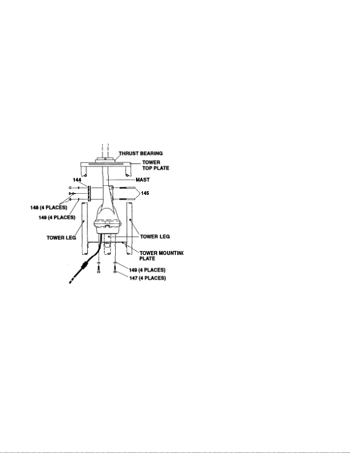
3. A telescoping or other type mast (see Figure
6) can also be used. This installation is
similar to Number 2 above and requires the
optional Heavy Duty Lower Mast Support
Kit and must be derated to 7.5 square feet.
UNBALANCED WEIGHT AND WIND
PRESSURE
I. Unbalanced Weight: Weight should be as
closely balanced as possible. Unbalanced
weight creates a bending moment of force
which is concentrated on the mast at the
point where it is clamped to the rotator. This
moment tends to strain the mast at that point
and also to bind the ball bearings by creating
excessive downward pressure on one side
and upward pressure on the other. Such
unbalance places additional stress on the
motor gear train. Unbalanced weight
becomes critical as the distance from the
antenna boom to the clamping point at the
rotator is increased.
2. Wind Pressure: Wind pressure against the
boom and elements produces a bending
force on the mast which can caus e the same
stresses as unbalanced weight. To strengthen
the installation to withstand unbalanced
weight and wind pressure the tip mast
should be as short and as strong as possible.
In multiple arrays the antenna with the most
wind area should be closest to the rotator.
In order to distribute the bending stress and
prevent fracture of the mast, the HAM IV rotator
includes a specially designed steel clamping
plate to clamp the mast to the rotator;
After procuring the type of tower or other
positioning mechanism of the owner's choice, the
next step is to wire the rotator to the control box
and check out its operation prior to installation.
WIRING AND CHECK-OUT
r
A. Decide the wire gauge (size) required and
procure the number of feet of the proper cable
(see Table 1).
Maximum Gauge for Gauge for
Length Terminals 1 & 2 Terminals 3-8
125' (38 m) #18 (1.19 mm) #20 (.97 mm)
200' (61 m) #16 (1.42 mm) #18 (1.19 mm)
300' (91 m) #14 (1.75 mm) #16 (1.42 mm)
Table 1
D. With the rotator sitting in the upright position
and connected to the control unit by the 8wire cable, plug the control unit power cord
into a receptacle.
E. Turn the power switch on. The meter should
be illuminated.
F. Depress the "Brake Release" (center) lever,
then release it. An audible click should be
heard in the rotator. This is the solenoid
operating the brake wedge.
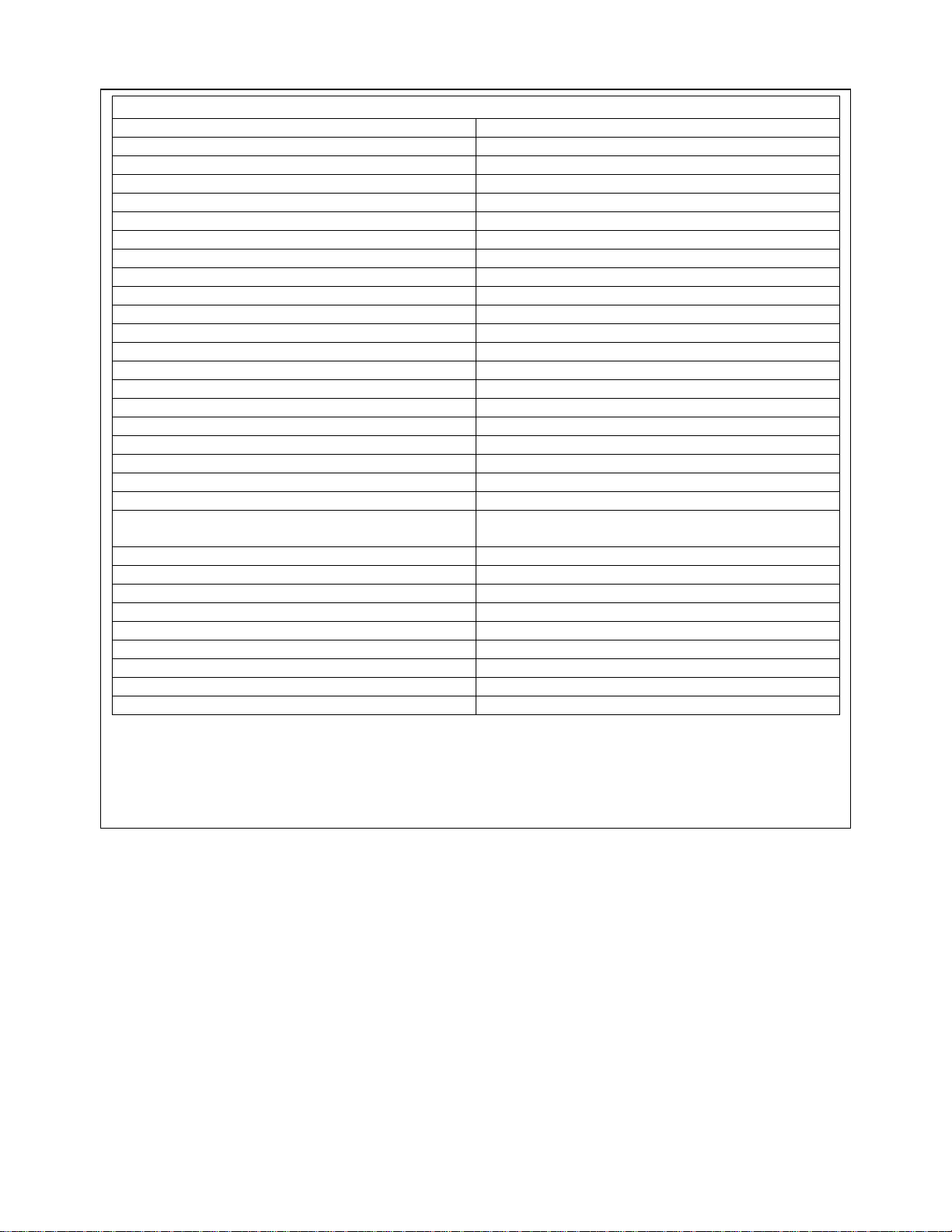
Control Cable Connector Attachments
NOTE: The specifications call for heavie
gauge wire in two locations. Leads #1 and #2
must be heavier gauge and less total lead
resistance.
B. Assemble the rotor cable as shown in Figure
1.
CAUTION
Shorts between terminals or grounded leads may
damage the rotator.
C. Temporarily attach the 4 1/4"-20 x 1 1/4"
screws (Item 147) to the bottom of the rotor
unit.
Figure 2
G. Depress the "Brake Release" (center) lever,
hold it, and simultaneously depress the
CCW direction switch (left). The rotator
should turn CCW (looking from the top).
This is S-E-NW-S. Release the CCW
direction switch; the rotator will coast down
and stop. Now release the brake switch. The
rotator is now locked into position.
H. Repeat the previous step for CW direction by
depressing the brake switch first, then the
CW direction switch (right).
CAUTION
It is best to release the direction switch just
prior to the end of rotation (extreme CW or
CCW position) in order not to cause undue
stress on the stop arm and/or the gears.
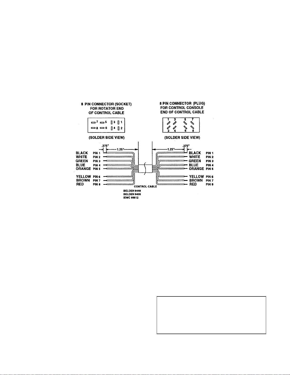
ROTATOR UNIT CONNECTOR MOUTING INSIDE TOWER
The Ham IV is now supplied with an 8 pin
Cinch® connector with lock. This connector is
not waterproof and requires a heatshrink "boot"
to keep water out. Slide the heatshrink (supplied)
over both connectors after attachment, and heat
the "rotor unit end" of the shrink-tube with a hot
air-gun or hair-dryer.
The bottom should be left open to "breathe". Seal
the top of the shrink-tube with black electrical
tape if necessary. Make sure that this connector
assembly is installed in a vertical position with
proper strain relief.
The rotator is mounted inside a tower (see Figure
4) to the flat tower plate by means of four (4)
bolts furnished in the hardware kit. Use the
following procedure:
1. Locate the rotator in the tower directly under
the bushing. Note that the tower plate must be
cut out to allow the connecting 8-wire cable
to pass through the plate.
Use the template in the back of the manual.
Too small of a hole will not allow the
connector to pass through.
2. Plug the connectors together and secure the
cable to the tower in such a manner that the
cable will not be strained.
Figure 3
Locking-Type "Cinch" Connectors
3. The rotator is attached to the tower plate by
p
g
g
r
means of four (4) bolts and lockwashers (see
Figure 4). The flat tower plate must be
drilled in four (4) places using the template
provided with this manual unless the tower
late is already properly drilled.
4. Tighten the four (4) bolts, but not to final
tightness. Observe how the rotator turns. It
must rotate in such a manner as to turn the
mast concentrically in the thrust bearing.
NOTE: Apply a coating of heavy-duty motor oil
or grease to the threads of the stainl ess steel bol ts
and U-bolts to prevent seizing.
On any inside tower installation, care must be
exercised to get the antenna mast shimmed to the
exact rotational center of the rotator. The
geometry is such that a mast of 2.062" (21/16"
[52 mm]) O.D. pipe will be exactly centered. If
the O.D. of your mast is less than this, you
should shim out to these dimensions.
6. If the rotator, top bushing and mast are
aligned, there should be unrestricted rotation
through 360°. If not, the rotator may have to be
moved slightly on the flat plate. If a high
quality bearing is used in the top of the tower
(recommended), the shimming procedure must
be done more carefully as closer tolerances are
required. It is important that the rotator does
not try to turn the mast eccentrically with the
top bushing or bearing.
Figure 4
Rotator Mountin
5. Trial assemble the mast to the top of the
rotator using the U-bolts, nuts and
lockwashers through the rotator and clamp
plate as shown in Figure 4. The maximum
mast diameter that may be used is 21/16"
O.D. We recommend 1 1/2" nominal steel
pipe with 1.9" O.D. in standard wall
thickness of .145". For stacked arrays or
very large beams, we recommend extra
heavy-duty wall thickness of .200". Both
steel pipes can be purchased t o specification
ASTM120.
in a Towe
7. Tighten the four (4) bolts carefully - to
approximately 100 inch-pounds of torque.
8. Insert the 1/4"-20 x 1 1/4" bolt with a lockin
nut into the center tapped hole in the clamp
plate. Tighten down to assure that the
antenna mast does not turn in the upper mast
support.
Return the rotator to the full CW "S"
position. Mount the beam on the mast
pointing South. The coaxial cable should be
looped in such a manner that it will not foul
or tangle when the beam turns around in a
circle to the full 360° counterclockwise
position.
 Loading...