

Husqvarna CR125 2012, WR125 2012 Owner's manual

CR 125 - CR 125 USA 2013
WR 125 - WR 125 USA 2013
Manuale utente_Owner’s manual_Manuel d’utilisateur_Benutzerhandbuch_Manual del usuario
CR 125
WR 125
EN
CR 125 - CR 125 USA 2013
WR 125 - WR 125 USA 2013
Ed. 05-2012 - Rev. 00
Unless specified, data and prescription are referred to all the models.
SPECIFICATIONS - OPERATION - MAINTENANCE
EN - 1

SPECIFICATIONS - OPERATION - MAINTENANCE
EN - 2
TABLE OF CONTENTS Page
PRESENTATION
IMPORTANT NOTICES...............................................................3
IDENTIFICATION DATA ............................................................. 5
CR - WR USA control location ................................................... 6
WR control location ................................................................7
TECHNICAL DATA ..................................................................... 8
LUBRICATION TABLE, SUPPLIES ................................................ 9
CONTROLS ............................................................................ 10
RIDING ................................................................................. 17
IGNITION SYSTEM/ELETTRICAL SYSTEM .................................. 41
APPENDIX ............................................................................. 44
PRE-DELIVERY INSPECTION .................................................... 47
ALPHABETICAL INDEX ............................................................ 48
PERIODIC MAINTENANCE -ADJUSTMENT ....................Appendix A
....................................................................... 3
•References to the “left” or “right” of the motorcycle are in
Note
the sense of a person facing forwards.
•Z: number of teeth
• A: Austria
AUS: Australia
B: Belgium
BR: Brazil
CDN: Canada
CH: Switzerland
D: Germany
E: Spain
F: France
FIN: Finland
GB: Great Britain
I: Italy
J: Japan
USA: United States of America
•Where not specified, all the data and the instructions are
referred to any and all Countries.
SPECIFICATIONS - OPERATION - MAINTENANCE
EN - 3
EN
PRESENTATION
Welcome to the Husqvarna motorcycling Family!
Your new Husqvarna motorcycle is designed and manufactured to be the finest in its field.
The instructions in this book have been prepared to provide
a simple and understandable guide for your motorcycle’s
operation and care.
Follow the instructions carefully to obtain maximum performance and your personal motorcycling pleasure. Your
owner’s manual contains instructions for owner care and
maintenance.
The main work of repair or maintenance requires the attention of a skilled mechanic and the use of special tools
and equipment.
Your Husqvarna dealer has the facilities, experience and original parts necessary to properly render this valuable service.
This “Owner’s Manual” is part and parcel of the motorcycle, hence, this had to
remain with the motorcycle even when
sold to another user.
This motorcycle uses components designed thanks to systems and state of the art technologies which are thereafter
tested in competition.
In competition motorcycles, every detail is verified after each
race in order to always guarantee better performance. For
correct functioning of the vehicle, it is necessary to follow the
maintenance and control table found on Appendix A.
IMPORTANT NOTICES
1) The CR models are guaranteed COMPETITION motorcycles
exempt from functional defects,
the suggested maintenance table for competition use is shown
on Appendix A.
2) WR vehicles are STREET
LEGAL motorcycles (with LIMITED
POWER ENGINE); they are guaranteed exempt from functional
defects and covered with legal
guarantee, if the STANDARD
CONFIGURATION is maintained
and the suggested maintenance
table, shown on Appendix A is
observed.
If WR vehicles are transformed
in COMPETITION MOTORCYCLES
(with FULL POWER ENGINE), the
suggested maintenance table for
competition use is shown on Appendix A.
CR 125
WR 125
MOTOCROSS
ENDURO

SPECIFICATIONS - OPERATION - MAINTENANCE
EN - 4
IMPORTANT
The reference for recognition of the guarantee will be the MOTORCYCLE CONFIGURATION, as shown below:
A) STANDARD MOTORCYCLE, STREET LEGAL: with LIMITED POWER
ENGINE
B) COMPETITION MOTORCYCLE, RACING USE: with FULL POWER
ENGINE
This motorcycles was not designed for long
trips with the engine always at maximum
rpm as can occur whilst travelling on roads
or highways. Long trips at full throttle can
cause severe damage to the engine.
This motorcycles is setup for competition use
and therefore guarantees maximum performance with the rider alone. It is thereby
not recommended to use the vehicle on circuits or off-road with a passenger.
ALWAYS keep in mind that these motorcycles have been designed
strictly for competition use, that is, for conditions of usage very
different from those presented on the road.
ALWAYS keep in mind that these motorcycles
have been designed strictly for competition
use, that is, for conditions of usage very different from those presented on the road.
In order to maintain the vehicle’s “Guarantee of Functionality”, the client must follow
the maintenance program indicated in the
user’s manual by carrying out maintenance
checks at authorized HUSQVARNA dealers.
The cost for substituting parts and for the labour necessary in order to respect the maintenance plan, is charged to the client.
NOTE: the guarantee is EXTINGUISHED in the
case where the motorcycle is rented.
Important Notice
Read this manual carefully and pay special attention to statements preceeded by the following words:
Warning*: Indicates a possibility of severe
personal injury or loss of life if instructions
are not followed.
Caution*: Indicates a possibility of personal
injury or equipment damage if instructions
are not followed.
Note*: Gives helpful information.
Parts Replacement
When parts replacement is required, use only Husqvarna ORIGINAL parts.
Warning*: After an upset, inspect the motorcycle carefully. Make sure that the throttle,
brake, clutch and all other systems are undamaged. Riding with a damaged motorcycle
can lead to a serious crash.
Warning*: Never attempt to start or operate
your motorcycle unless you are wearing appropriate protective clothing. Always wear a
motorcycle helmet, motorcycle boots, gloves,
goggles and other appropriate protective
clothing.
Warning*: This motorcycle is a state of the
art competition bike. Do not attempt to start
or ride this motorcycle until you have received expert instruction and are in excellent
physical condition.
PRECAUTIONS FOR CHILDREN
WARNING
• Park the vehicle where it is unlikely to
be bumped into or damaged. Even slight or
involuntary bumps can cause the vehicle to
topple over, with subsequent risk of serious
harm to people or children.
• To prevent the vehicle from tipping over,
never park it on soft or uneven ground, nor
on asphalt strongly heated by the sun.
•Engine and exhaust pipes become very hot
during riding. Always park your motorcycle
where people or children can not easily reach
these parts, in order to avoid serious burns.
SPECIFICATIONS - OPERATION - MAINTENANCE
EN - 5
EN
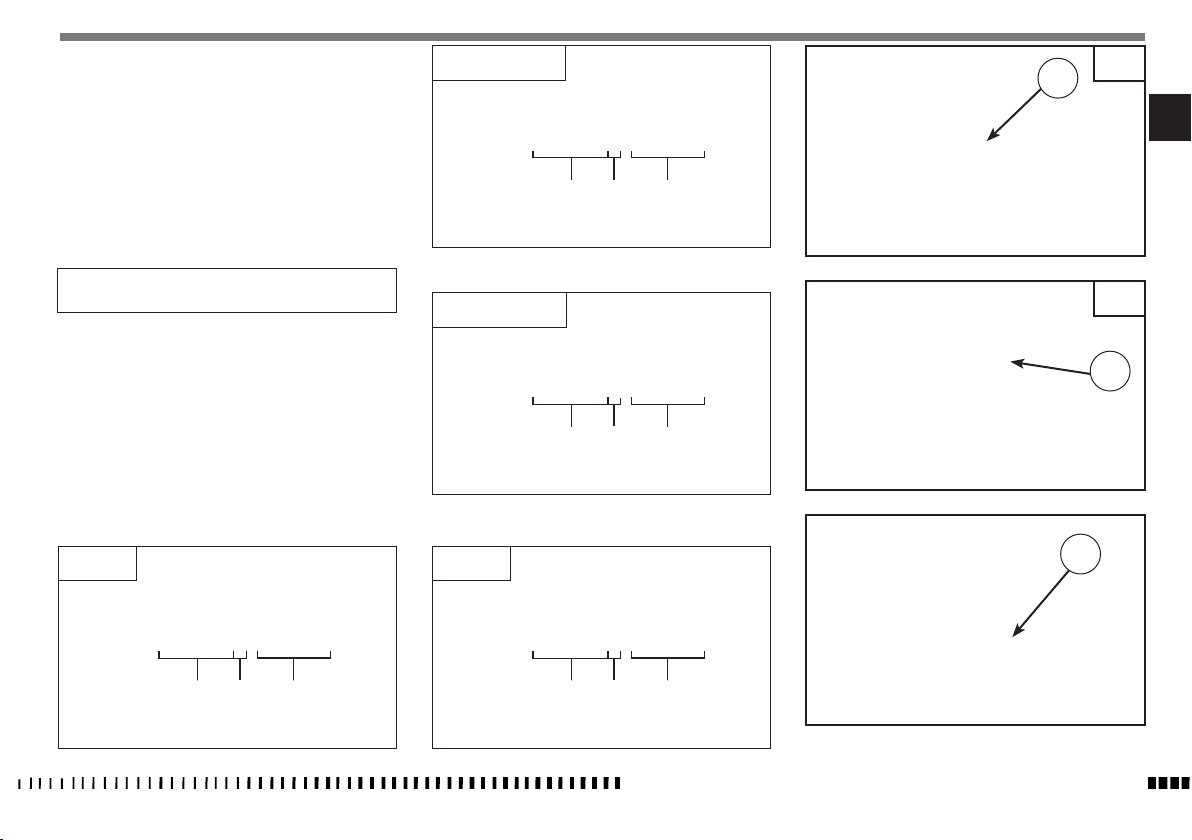
IDENTIFICATION DATA
The engine number is printed on the upper side of the engine
case, whereas the frame number is printed on the steering tube.
Always state the number stamped on the frame
(and write it on this booklet), when placing orders for spare
parts, or when asking for informations about your motorcicle.
FRAME NUMBER
CR 125 USA
ZKH CR123# DV 000000
(l) (▲)
CR
1
(
♦
)
VEHICLE IDENTIFICATION NUMBER (V.I.N.)
The full 17-digit serial, or Vehicle Identification Number, is
stamped on the steering tube (R.H. side).
(
l
) = Model designation
(▲) = Model Year (2013)
♦
) = Progressive no.
(
CR 125
ZKH 4H00AA DV 050001
(
♦
(l) (▲)
)
WR 125 USA
ZKH WR123# DV 000000
(l) (▲)
WR 125
ZKH 4H00AA DV 000001
(l) (▲)
(
♦
)
(
♦
)
1. Frame serial number
2. Engine serial number
WR
1
2
SPECIFICATIONS - OPERATION - MAINTENANCE
EN - 6
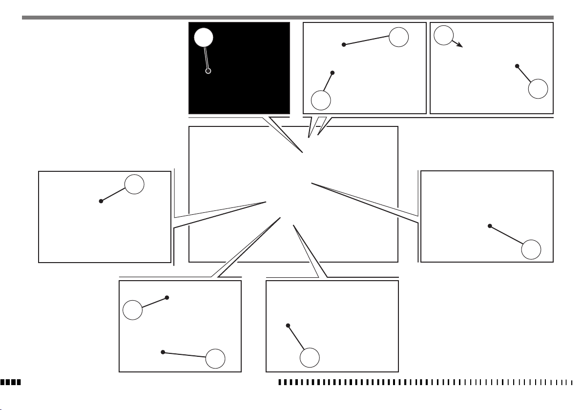
CR - WR USA CONTROL LOCATION
1. Front brake lever
2. Throttle grip
3. Engine stop button
4. Rear brake control pedal
5. Starting pedal
6. Clutch control lever
7. Fuel tank filler cap
8. Gearbox control pedal
9. Choke (L.H. side)
10. Fuel cock
9
7
2
3
6
1
10
5
4
8
SPECIFICATIONS - OPERATION - MAINTENANCE
EN - 7
EN
WR CONTROL LOCATION
1. Front brake lever
2. Throttle grip
3. L.H. commutator
4. Rear brake control pedal
5. Starting pedal
6. Clutch control lever
7. Fuel tank filler cap
8. Gearbox control pedal
9. Choke (L.H. side)
10. Fuel cock
7
2
3
6
1
9
10
5
4
8

SPECIFICATIONS - OPERATION - MAINTENANCE
EN - 8
TECHNICAL DATA
ENGINE
Type ..............................................single cylinder, 2 stroke
Cooling ........................................................................ liquid
Bore ............................................................ 2.13 in. (54 mm)
Stroke ......................................................2.15 in. (54,5 mm)
Displacement ................................... 7.62 in3. (124,82 cm
Compression ratio
(with closed ports) ..........................................................8,8:1
Starting ................................................................kick start
TIMING SYSTEM
..........lamellar valve on suction in the crankcase and
Type
H.T.S. valve with mechanical control on the exhaust
LUBRICATION
Engine . . . . . . . . . . . . . . . . . . . . 4% (1:25) of oil-gasoline mix
during running in; NOT LESS than 3% (1:33)when running in is
over
Primary drive transmission/Gearbox . .by the oil contained in
the crankcase
IGNITION
Type...... . . . . . . . . . . . . . . . . . . . . . . . . . . . . electronic digital
capacitor-discharge type, with variable advance
Spark plug type . . . . . . . . . . . CHAMPION QN B4/NGK BR9EG
Gap . . . . . . . . . . . . . . . . . . . . . . . . . . . .0.0236 in. (0,6 mm)
FUEL SYSTEM
Type..........................................Carburettor “Mikuni” TMX 38
Venturi diameter ............................................1.5 in. (38 mm)
High speed jet (CR) ...........................................................460
High speed jet (WR) ..........................................................380
Low speed jet (CR) ..............................................................35
3
Low speed jet (WR) .............................................................15
)
Starting jet (CR) ..................................................................80
Starting jet (WR) .................................................................50
Main nozzle .............................................................R-8 (914)
Floater (n° 2) .................................................................g 6,1
Throttle piston (CR) ............................................................4,0
Throttle piston (WR) ...........................................................5,0
Metering pin ...............................................................6BFY43
Metering pin slot (CR) .......................................................3rd
Metering pin slot (WR) ......................................................2nd
Idle mixture adjusting screw (CR) ...................... rounds 1+1/4
Idle mixture adjusting screw(WR) ...................... rounds 1+1/2
PRIMARY DRIVE
Drive pinion gear- Clutch ring gear .........................Z 22- Z 71
Transmission ratio .........................................................3,227
CLUTCH
Type ......oil bath multiple disc clutch, mechanical control
TRANSMISSION
Type........................................ constant mesh gear type
Transmission ratio
1st gear . . . . . . . . . . . . . . . . . . . . . . . . . . . .2,357 (z 33/14)
2nd gear ............................1,866 (z 28/15)
3rd gear ............................1,579 (Z 30/19)
4th gear . . . . . . . . . . . . . . . . . . . . . . . . . . . .1,350 (Z 24/22)
5th gear . . . . . . . . . . . . . . . . . . . . . . . . . . . .1,181 (Z 26/22)
6th gear . . . . . . . . . . . . . . . . . . . . . . . . . . . .1,000 (Z 21/21)
SECONDARY DRIVE
Transmission sprocket- Rear wheel sprocket ............ Z 13- Z 50
Transmission ratio ..........................................................3,846
FINAL RATIOS
1st gear ......................................................................29,258
2nd gear ......................................................................23,170
3rd gear .....................................................................19,599
4th gear .......................................................................16,757
5th gear ......................................................................14,669
6th gear ......................................................................12,412
FRAME
Type............................... Steel single tube cradle (roud tubes);
light alloy rear frame.
FRONT SUSPENSION
Type...................”Upside-down” telescopic hydraulic front fork
with advanced axle (adjustable in compression and rebound
stroke); stanchions tubes Ø 1.89 in. (Ø 48 mm)
Legs axis stroke .......................................11.8 in. (300 mm)
REAR SUSPENSION
Type..............progressive with hydraulic single shock absorber
Wheel stroke ............................................11.6 in. (296 mm)
FRONT BRAKE
Type fixed disc Ø 10.24 in. (Ø 260) “Wave” type with hydraulic
control and floating caliper
REAR BRAKE
Type................... floating disc, Ø 9.45 in. (Ø240) “Wave” type
with hydraulic control and floating caliper
SPECIFICATIONS - OPERATION - MAINTENANCE
EN - 9
EN
RIMS
Front .....................................................in light alloy: 1,6x21”
Rear (CR) ............................................ in light alloy: 2,15x19”
Rear (WR) ...........................................in light alloy: 2,15x18”
TYRES
Front (CR) ...........................................................80/100x21”
Front (WR) ............................................................90/90x21”
Rear (CR) .......................................................... 100/90x19”
Rear (WR) .......................................................... 120/90x18”
Cold tire pressure
(front) (*).............................12.8÷14.2 psi (0,9÷1,0 Kg/cm
(front) (%) ............................................15.6 psi (1,1 Kg/cm2)
(rear) (*) ..............................11.4÷12.8 psi (0,8÷0,9 Kg/cm2)
(rear) (%) .............................................14.2 psi (1,0 Kg/cm2)
(*) Racing use - (%) Road use
DIMENSION, WEIGHT, CAPACITY
Wheelbase (CR) ....................................57.48 in. (1460 mm)
Wheelbase (WR) ...................................57.68 in. (1465 mm)
Overall length(CR) ...................................87.2 in. (2215 mm)
Overall length (WR) ...............................88.98 in. (2260 mm)
Overall width (CR) ....................................32.28 in. (820 mm)
Overall width (WR) ...................................33.07 in. (840 mm)
Overall height (CR) ...............................51.38 in. (1305 mm)
Overall height (WR) ..............................51.18 in. (1300 mm)
Saddle height (CR) ................................... 38.78 in. (985 mm)
Saddle height (WR) .................................. 38.38 in. (975 mm)
2
)
Minimum ground clearance (CR) ..............12.79 in. (325 mm)
Minimum ground clearance (WR) ...............12.4 in. (315 mm)
Kerb weight, without fuel (CR) ......................202.8 lb (92 kg)
Kerb weight, without fuel (WR) .....................211.6 lb (96 kg)
Fuel tank capacity,
(1.32 Imp. quarts, 1.59 U.S. quart, 1,5 l reserve included)
1.54 Imp. gall.,
1.85 U.S. gall.
7 l
Coolant capacity .................................0.97÷1.14 Imp. Quarts ,
1.16÷1.37 U.S. Quarts
1,1÷1,3 l
Transmission oil ..........................................0.70 Imp. Quarts ,
0.85 U.S. Quarts
0,8 l
TABLE FOR LUBRICATION, SUPPLIES
Engine lubricating oil
CASTROL A747
Gearbox and primary drive lubricating oil
CASTROL POWER 1 RACING 10W-40
Engine coolant
CASTROL MOTORCYCLE COOLANT
Brake system fluid
CASTROL RESPONSE SUPER DOT 4
Grease lubrication
CASTROL PASTE TA GREASE
Final drive chain lubrication
CASTROL CHAIN LUBE RACING
Front fork oil
Kayaba KHL15-11
Oil for rear shock absorber
CASTROL SYNTHETIC FORK OIL 5W
Electric contact protection
CASTROL METAL PARTS CLEANER
CASTROL MOTORCYCLE DWF
Fillers for radiator
AREXONS TURAFALLE LIQUIDO
SPECIFICATIONS - OPERATION - MAINTENANCE
EN - 10
CONTROLS
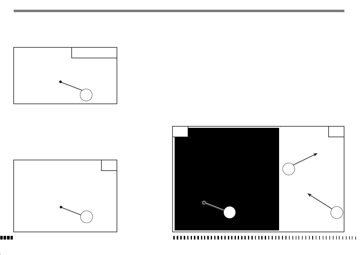
CR - WR USA Fuel cock
The cock is screw-type and is on the left of the tank; loosen by
turning ring nut (1) to open, tighten to close.
CR - WR USA
1
WR Fuel cock
The cock (2) set on left side of tank has three positions:
OFF - closed; no fuel outlet;
ON - open; fuel outflows from the main flow;
RES - reserve; fuel outflows from the reserve flow.
When running, should feed problem ensue, set cock lever on RES
position. After filling up, take the cock in ON position again.
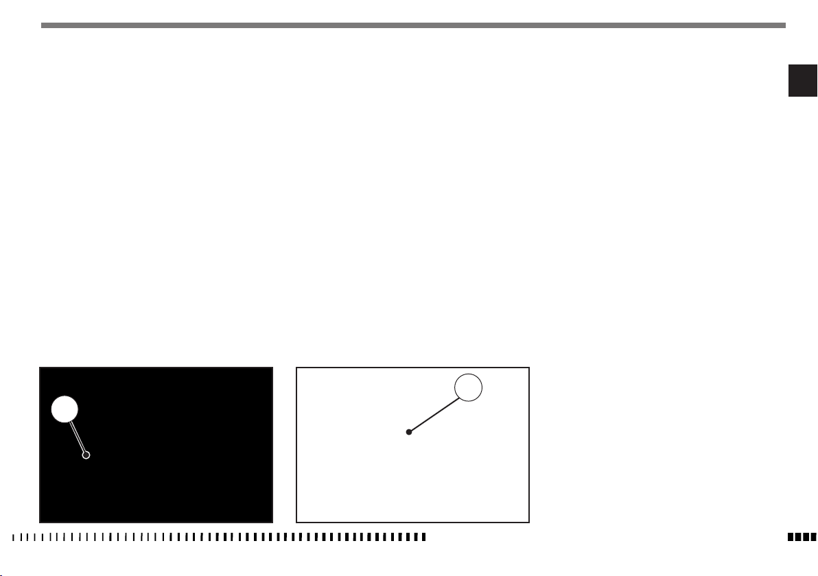
SIDESTAND
A sidestand (1) is supplied with every motorcycle.
WARNING*: The stand is designed to support the weight of the MOTORCYCLE ONLY. Do
not sit on the motorcycle using the stand for
support as this could cause structural failure
to the stand and could cause serious bodily
injury.
WR: Periodically check the side stand (see “Periodical maintenance card”); check that the springs are not damaged and that
the side stand freely moves. If the side stand is noisy, lubricate
the fastening pivot (A).
CR WR
WR
2
A
1
1
SPECIFICATIONS - OPERATION - MAINTENANCE
EN - 11
EN
FUEL
The motorcycle is equipped with 2 stroke engine that requires
a gasoline-oil mixture. Recommended fuel: premium grade unleaded fuel (R.O.N. 98).
Note*: Do not continue operation if the engine pings or knocks. The engine will be
damaged and could seize.
WARNING*: If “knocking” or “pinging”
occurs, try a different brand of gasoline or
higher octane grade.
WARNING*: Gasoline is extremely flammable and can be explosive under certain conditions. Always stop the engine and do not
smoke or allow flames or sparks in the area
where the motorcycle is refueled or gasoline
is stored.
WARNING*: Do not overfill the tank. After refueling, make sure the tank cap (2) is closed
securely.
2
CARBURETOR CHOKE
The starter knob (1), located on the left side of the carburetor, is
used to enrich the mixture during the engine start.
Pull out the knob to open the starter, and pull the lever upwards
to close it.
1
SPECIFICATIONS - OPERATION - MAINTENANCE
EN - 12
DIGITAL INSTRUMENT, WARNING LIGHTS (WR)
- The instrument functions are the following, as shown below.
1- SPEED (Km/h or mph) / ODO
The motorcycle is equipped with a digital instrument; on the
instrument are located 2 warning lights too: high beam and
blinkers.
1- BLUE warning light “HIGH BEAM”
2- GREEN warning light “BLINKERS”
The instrument display illuminates (amber colour) when the
engine started.
NOTES
- Every time the engine starts, for the first 2 seconds, the
instrument shows the version of the checking SW; after the
check, the instrument shows the last planned function.
- Whenthemotorcycle engineisOFF,theinstrument doesn’t
also show its functions.
- To select the instrument functions and to set to zero the
functions, use the SCROLL knob (A).
2
1
1- SPEED / ODO
2- SPEED / CLOCK
3- SPEED / TRIP
4- SPEED / CHRONO
1- SPEED / ODO
.................
- SPEED: motorcycle speed- maximum value: 299 Km/h or 299
mph;
- ODO: odometer- maximum value: 99999 km;
To replace kilometers with miles or miles with kilometers proceed as follows:
1) set to figure 1, stop the engine and push the knob SCROLL
(A);
2) Start the engine holding pushed the button SCROLL (A) until
the symbol “Km/h” will be displayed;
3) then the symbols “Km/h” and “Mph Miles” will be displayed
alternatively. Push again the SCROLL (A) button when the
unit you wish to use is displayed.
A
A
SPECIFICATIONS - OPERATION - MAINTENANCE
EN - 13
EN
2- SPEED / CLOCK
- SPEED: motorcycle speedmaximum value: 299 Km/h o 299
mph;
- CLOCK: clock- Reading from 0:00 to 23:59:59;
To reset the clock, push the knob SCROLL (A) for more than 3
seconds in order to increase the hours; release the knob and
then, after 3 seconds, it is possible to increase the minutes;
3- SPEED / TRIP 1
- SPEED: motorcycle speedmaximum value: 299 Km/h o 299
mph
- TRIP 1: distance- maximum value: 999.9 km (the data will be
lost with voltage lower than 6V).
To setup the TRIP, push the SCROLL (A) button holding down
more than 3 seconds.
4- SPEED / CHRONO (STP)
- SPEED: motorcycle speedmaximum value: 299 Km/h o 299
mph;
- STP 1: miles/kilometers covered time;
- Reading from 0:00 to 99:59:59 (the data will be lost with
voltage lower than 6V).
To activate the function STP 1, push the knob SCROLL (A) for
more than 3 seconds.
- 1st step: function ON;
- 2nd step: stop to the counters;
- 3rd step: STP 1 zero-setting; TRIP 1 and AVS 1 data zerosetting;
- 4th step: function ON;
- 5th step: stop to the counters;
.............................
and so following
A
A
A
SPECIFICATIONS - OPERATION - MAINTENANCE
EN - 14
THROTTLE CONTROL
The throttle knob (1), is located on the right hand side of the
handlebar. The position of the throttle control can be adjusted
by loosening the two fastenig screws (A).
CAUTION
Do not forget to tighten the screws (A) after
the adjustment.
FRONT BRAKE CONTROL
The brake control lever (2) is located on the right hand side of
the handlebar. The position of the throttle control can be adjusted by loosening the two fastenig screws (B).
CAUTION
Do not forget to tighten the screws (B) after
the adjustment.
STEERING LOCK (WR)
The motorcycle is equipped with a steering lock (1) on the R.H.
side of the steering head tube.
To lock it, procede as follows: turn the handlebar leftwards,
place the key in lock and turn counterclockwise. Push the key
inwards (if necessary, turn to and from). Turn the key clockwise
and remove it from the lock.
To unlock the steering lock, reverse the above procedure.
B
A
1
1
2
 Loading...