

Page 1
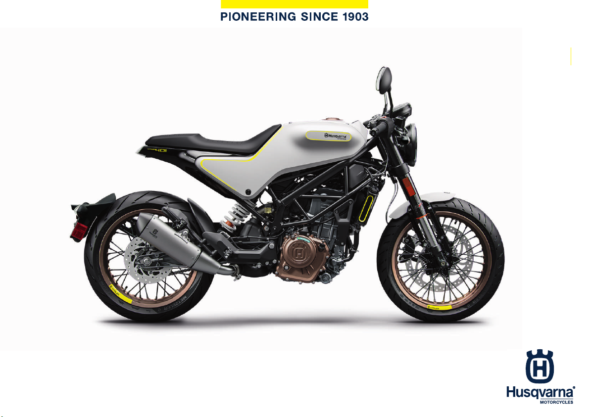
OWNER'S MANUAL 2018
VITPILEN 401
Art. no. 3402207en
Page 2

Page 3
DEAR HUSQVARNA MOTORCYCLES CUSTOMER
DEARHUSQVARNA MOTORCYCLESCUSTOMER
Congratulations on your decision to purchase a Husqvarna motorcycle. You are now the owner of a state-ofthe-art sports motorcycle that will give you enormous pleasure if you service and maintain it properly.
We hope you enjoy riding this motorcycle!
Enter the serial numbers of your vehicle below.
Chassis number ( p. 32) Dealer's stamp
Engine number ( p. 33)
Key number ( p. 34)
The Owner's Manual contained the latest information for this model series at the time of going to print. However, minor differences due to further developments in design cannot be ruled out completely.
All specifications are non-binding. Husqvarna Motorcycles GmbH specifically reserves the right to modify or
delete technical specifications, prices, colors, forms, materials, services, designs, equipment, etc., without prior
notice and without specifying reasons, to adapt these to local conditions, as well as to stop production of a
particular model without prior notice. Husqvarna Motorcycles accepts no liability for delivery options, deviations from illustrations and descriptions, as well as misprints and other errors. The models portrayed partly
contain special equipment that does not belong to the regular scope of supply.
© 2018 Husqvarna Motorcycles GmbH, Mattighofen Austria
All rights reserved
*3402207en*
3402207en
01/2018
Page 4
DEAR HUSQVARNA MOTORCYCLES CUSTOMER
Reproduction, even in part, as well as copying of all kinds, is permitted only with the express written permission
of the copyright owner.
ISO 9001(12 100 6061)
Husqvarna Motorcycles applies quality assurance processes that lead to the highest possible
product quality as defined in the ISO 9001 international quality management standard.
Issued by: TÜV Management Service
Husqvarna Motorcycles GmbH
Stallhofnerstraße 3
5230 Mattighofen, Austria
This document is valid for the following models:
VITPILEN 401 US (F2375R1)
2
Page 5

TABLEOF CONTENTS
1 MEANS OF REPRESENTATION........................ 9
1.1 Symbols used ....................................... 9
1.2 Formats used...................................... 10
2 SAFETY ADVICE ............................................. 11
2.1 Use definition...................................... 11
2.2 Misuse................................................. 11
2.3 Safety advice ...................................... 11
2.4 Degrees of risk and symbols .............. 12
2.5 Overview of labels............................... 14
2.6 Consumer rights ................................. 18
2.7 Operating noise warning..................... 19
2.8 Noise emission warranty..................... 19
2.9 Reporting safety defects..................... 19
2.10 Tampering warning ............................. 20
2.11 Safe operation..................................... 21
2.12 Protective clothing.............................. 22
2.13 Work rules........................................... 22
2.14 Environment........................................ 23
2.15 Owner's Manual.................................. 23
3 IMPORTANT NOTES....................................... 24
3.1 Manufacturer and implied warranty.... 24
3.2 Operating and auxiliary substances ... 24
TABLE OF CONTENTS
3.3 Spare parts, accessories .................... 24
3.4 Service ................................................ 25
3.5 Figures ................................................ 25
3.6 Customer service................................ 25
4 VIEW OF VEHICLE .......................................... 28
4.1 View of vehicle, front left (example) .... 28
4.2 View of vehicle, rear right
(example)............................................. 30
5 SERIAL NUMBERS.......................................... 32
5.1 Chassis number.................................. 32
5.2 Type label............................................ 32
5.3 Engine number.................................... 33
5.4 Key number......................................... 34
6 CONTROLS..................................................... 35
6.1 Clutch lever......................................... 35
6.2 Hand brake lever................................. 35
6.3 Throttle grip......................................... 36
6.4 Switches on the left side of the
handlebar............................................ 36
6.4.1 High beam flasher button............... 36
6.4.2 Light switch .................................... 37
6.4.3 Turn signal switch .......................... 37
3
Page 6

TABLE OF CONTENTS
6.4.4 Horn button .................................... 38
6.5 Switches on the right side of the
handlebar............................................ 38
6.5.1 Emergency OFF switch .................. 38
6.5.2 Electric starter button..................... 39
6.6 Ignition/steering lock........................... 39
6.7 Locking the steering ........................... 40
6.8 Unlocking the steering........................ 41
6.9 Opening the filler cap.......................... 41
6.10 Closing the filler cap ........................... 43
6.11 Seat lock ............................................. 44
6.12 Tool set ............................................... 44
6.13 Grab handle ........................................ 45
6.14 Passenger foot pegs........................... 45
6.15 Shift lever ............................................ 46
6.16 Foot brake lever.................................. 47
6.17 Side stand........................................... 47
7 ERGONOMICS................................................ 49
7.1 Adjusting the basic position of the
hand brake lever ................................. 49
7.2 Adjusting the basic position of the
clutch lever.......................................... 49
7.3 Adjusting the shift lever ...................... 50
8 COMBINATION INSTRUMENT ....................... 52
8.1 Combination instrument ..................... 52
8.2 Activation and test .............................. 53
8.3 Warning notes..................................... 54
8.4 Indicator lamps ................................... 59
8.5 Shift warning light ............................... 61
8.6 Display ................................................ 63
8.7 Fuel level display................................. 64
8.8 Coolant temperature indicator............ 65
8.9 Function buttons................................. 66
8.10 Info display.......................................... 67
8.11 ODO display........................................ 68
8.11.1 Fuel Range ..................................... 68
8.11.2 Service............................................ 69
8.12 TRIP 1 display..................................... 70
8.12.1 Time Trip 1 ..................................... 71
8.12.2 Average Speed Trip1...................... 72
8.12.3 Avg F.C. Trip 1 ............................... 73
8.13 TRIP 2 display..................................... 74
8.13.1 Time Trip 2 ..................................... 74
8.13.2 Average Speed Trip2...................... 75
8.13.3 Avg F.C. Trip 2 ............................... 76
8.14 Setting the units.................................. 77
8.15 Setting the clock................................. 78
4
Page 7

TABLE OF CONTENTS
8.16 Adjusting the shift speed RPM1 ......... 79
8.17 Adjusting the shift speed RPM2 ......... 80
9 PREPARING FOR USE.................................... 82
9.1 Advice on preparing for first use......... 82
9.2 Running in the engine ......................... 84
9.3 Loading the vehicle............................. 84
10 RIDING INSTRUCTIONS ................................. 87
10.1 Checks and maintenance measures
when preparing for use....................... 87
10.2 Starting ............................................... 88
10.3 Starting off .......................................... 90
10.4 Shifting, riding..................................... 91
10.5 Applying the brakes ............................ 96
10.6 Stopping, parking ............................... 98
10.7 Transport........................................... 100
10.8 Refueling........................................... 101
11 SERVICE SCHEDULE.................................... 103
11.1 Additional information....................... 103
11.2 Required work................................... 103
11.3 Recommended work......................... 106
12 TUNING THE CHASSIS................................. 107
12.1 Adjusting the spring preload of the
shock absorber ............................. 107
13 SERVICE WORK ON THE CHASSIS ............. 108
13.1 Raising the motorcycle with the
rear lifting gear .................................. 108
13.2 Removing the rear of the
motorcycle from the lifting gear........ 110
13.3 Lifting the motorcycle with the
front lifting gear................................. 112
13.4 Taking the motorcycle off the front
lifting gear ......................................... 113
13.5 Cleaning the dust boots of the fork
legs ................................................... 114
13.6 Removing the seat............................ 115
13.7 Mounting the seat............................. 116
13.8 Removing the left side cover ........ 116
13.9 Installing the left side cover .......... 119
13.10 Removing the right side cover ...... 121
13.11 Installing the right side cover ........ 124
13.12 Removing the license plate holder.... 127
13.13 Installing the license plate holder ..... 131
13.14 Checking for chain dirt
accumulation .................................... 136
5
Page 8
TABLE OF CONTENTS
13.15 Cleaning the chain ............................ 136
13.16 Checking the chain tension .............. 138
13.17 Adjusting the chain tension............... 139
13.18 Checking the chain, rear sprocket,
and engine sprocket ......................... 141
14 BRAKE SYSTEM ........................................... 144
14.1 Antilock brake system (ABS)............. 144
14.2 Checking the brake discs ................. 146
14.3 Checking the front brake fluid
level................................................... 148
14.4 Adding front brake fluid ................ 149
14.5 Checking the front brake linings ....... 152
14.6 Checking the rear brake fluid level ... 153
14.7 Adding rear brake fluid .................. 154
14.8 Checking the rear brake linings ........ 156
14.9 Checking the free travel of the foot
brake lever ........................................ 158
14.10 Adjusting the free travel of the foot
brake lever .................................... 159
15 WHEELS, TIRES............................................ 161
15.1 Removing the front wheel ............. 161
15.2 Installing the front wheel ............... 162
15.3 Removing the rear wheel .............. 165
15.4 Installing the rear wheel ................ 167
15.5 Checking the rear hub rubber
dampers ........................................ 170
15.6 Checking the tire condition............... 171
15.7 Checking the tire air pressure........... 174
15.8 Checking spoke tension ................... 175
16 ELECTRICAL SYSTEM.................................. 176
16.1 Removing the battery .................... 176
16.2 Installing the battery ...................... 179
16.3 Recharging the battery ................. 181
16.4 Changing the ABS fuses................... 184
16.5 Changing the fuses of individual
power consumers ............................. 187
16.6 Changing the turn signal bulb........... 190
16.7 Checking the headlight setting ......... 191
16.8 Adjusting the headlight range........... 192
16.9 Diagnostics connector...................... 193
16.10 Front ACC1 and ACC2 ..................... 194
16.11 ACC2 rear ......................................... 194
17 COOLING SYSTEM....................................... 195
17.1 Cooling system ................................. 195
17.2 Checking the antifreeze and
coolant level...................................... 196
6
Page 9

TABLE OF CONTENTS
17.3 Checking the coolant level................ 199
17.4 Draining the coolant ...................... 201
17.5 Filling/bleeding the cooling
system ........................................... 202
17.6 Changing the coolant .................... 205
18 TUNING THE ENGINE................................... 209
18.1 Checking the clutch lever play.......... 209
18.2 Adjusting play in the clutch
lever ............................................... 210
19 SERVICE WORK ON THE ENGINE ............... 211
19.1 Checking the engine oil level ............ 211
19.2 Changing the engine oil and oil
filter, cleaning the oil screens ....... 212
19.3 Adding engine oil .............................. 216
20 CLEANING, CARE......................................... 218
20.1 Cleaning the motorcycle................... 218
20.2 Checks and maintenance steps for
winter operation................................ 221
21 STORAGE...................................................... 223
21.1 Storage ............................................. 223
21.2 Preparing for use after storage ......... 225
22 TROUBLESHOOTING ................................... 226
23 TECHNICAL DATA ........................................ 229
23.1 Engine ............................................... 229
23.2 Engine tightening torques................. 230
23.3 Capacities......................................... 235
23.3.1 Engine oil...................................... 235
23.3.2 Coolant......................................... 235
23.3.3 Fuel............................................... 235
23.4 Chassis ............................................. 235
23.5 Electrical system............................... 237
23.6 Tires .................................................. 238
23.7 Fork................................................... 238
23.8 Shock absorber ................................ 239
23.9 Chassis tightening torques ............... 239
24 SUBSTANCES............................................... 246
25 AUXILIARY SUBSTANCES............................ 249
26 STANDARDS................................................. 251
27 INDEX OF SPECIAL TERMS ......................... 252
28 LIST OF ABBREVIATIONS ............................ 253
29 LIST OF SYMBOLS ....................................... 254
29.1 Yellow and orange symbols.............. 254
7
Page 10

TABLE OF CONTENTS
29.2 Green and blue symbols................... 254
INDEX .................................................................... 255
8
Page 11
1.1 Symbols used
The meaning of specific symbols is described below.
Indicates an expected reaction (e.g. of a work step or a function).
Indicates an unexpected reaction (e.g. of a work step or a function).
All work marked with this symbol requires specialist knowledge and technical understanding. In the interests of your own safety, have these jobs performed by an authorized Husqvarna Motorcycles workshop. There, your motorcycle will be optimally cared for by specially
trained experts using the specialist tools required.
Indicates a page reference (more information is provided on the specified page).
Indicates information with more details or tips.
MEANS OF REPRESENTATION 1
Indicates the result of a testing step.
9
Page 12
1 MEANS OF REPRESENTATION
Indicates a voltage measurement.
Indicates a current measurement.
Indicates the end of an activity, including potential rework.
1.2 Formats used
The typographical formats used in this document are explained below.
Proprietary name Indicates a proprietary name.
®
Name
Brand™ Indicates a brand available on the open market.
Underlined terms Refer to technical details of the vehicle or indicate technical terms, which
Indicates a protected name.
are explained in the glossary.
10
Page 13
SAFETY ADVICE 2
2.1 Use definition
This vehicle has been designed and built to withstand the normal stresses and strains of road use. This vehicle
is not suitable for use on race tracks or offroad.
Info
This vehicle is only authorized for operation on public roads in its homologated version.
2.2 Misuse
The vehicle must only be used as intended.
Dangers can arise for people, property and the environment through use not as intended.
Any use of the vehicle beyond the intended and defined use constitutes misuse.
Misuse also includes the use of operating and auxiliary fluids which do not meet the required specification for
the respective use.
2.3 Safety advice
A number of safety instructions need to be followed to operate the product described safely. Therefore read
this instruction and all further instructions included carefully. The safety instructions are highlighted in the text
and are referred to at the relevant passages.
11
Page 14
2 SAFETY ADVICE
Info
Various information and warning labels are attached in prominent locations on the product described.
Do not remove any information or warning labels. If they are missing, you or others may not recognize
dangers and may therefore be injured.
2.4 Degrees of risk and symbols
Danger
Identifies a danger that will immediately and invariably lead to fatal or serious permanent injury if the
appropriate measures are not taken.
Warning
Identifies a danger that is likely to lead to fatal or serious injury if the appropriate measures are not
taken.
Caution
Identifies a danger that may lead to minor injuries if the appropriate measures are not taken.
Note
Identifies a danger that will lead to considerable machine and material damage if the appropriate measures are
not taken.
Note
Indicates a danger that will lead to environmental damage if the appropriate measures are not taken.
12
Page 15

SAFETY ADVICE 2
13
Page 16
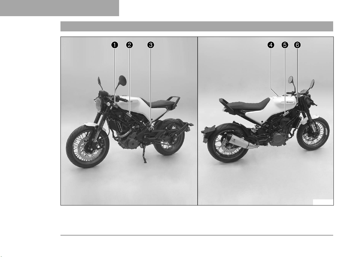
2 SAFETY ADVICE
2.5 Overview of labels
14
E01139-10
Page 17
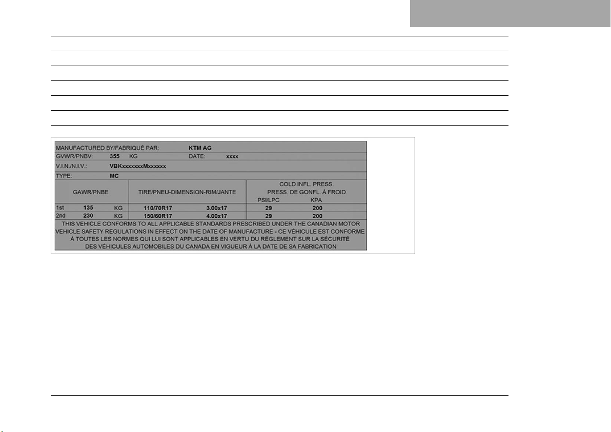
1 Type label for Canada
2 Information on emissions control
3 Information on chain tension
4 Information on preparations for use
5 Information on noise emissions
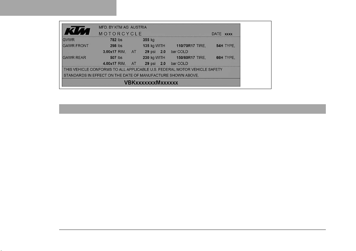
6 Type label for USA
Type label for Canada
SAFETY ADVICE 2
F01415-01
15
Page 18
2 SAFETY ADVICE
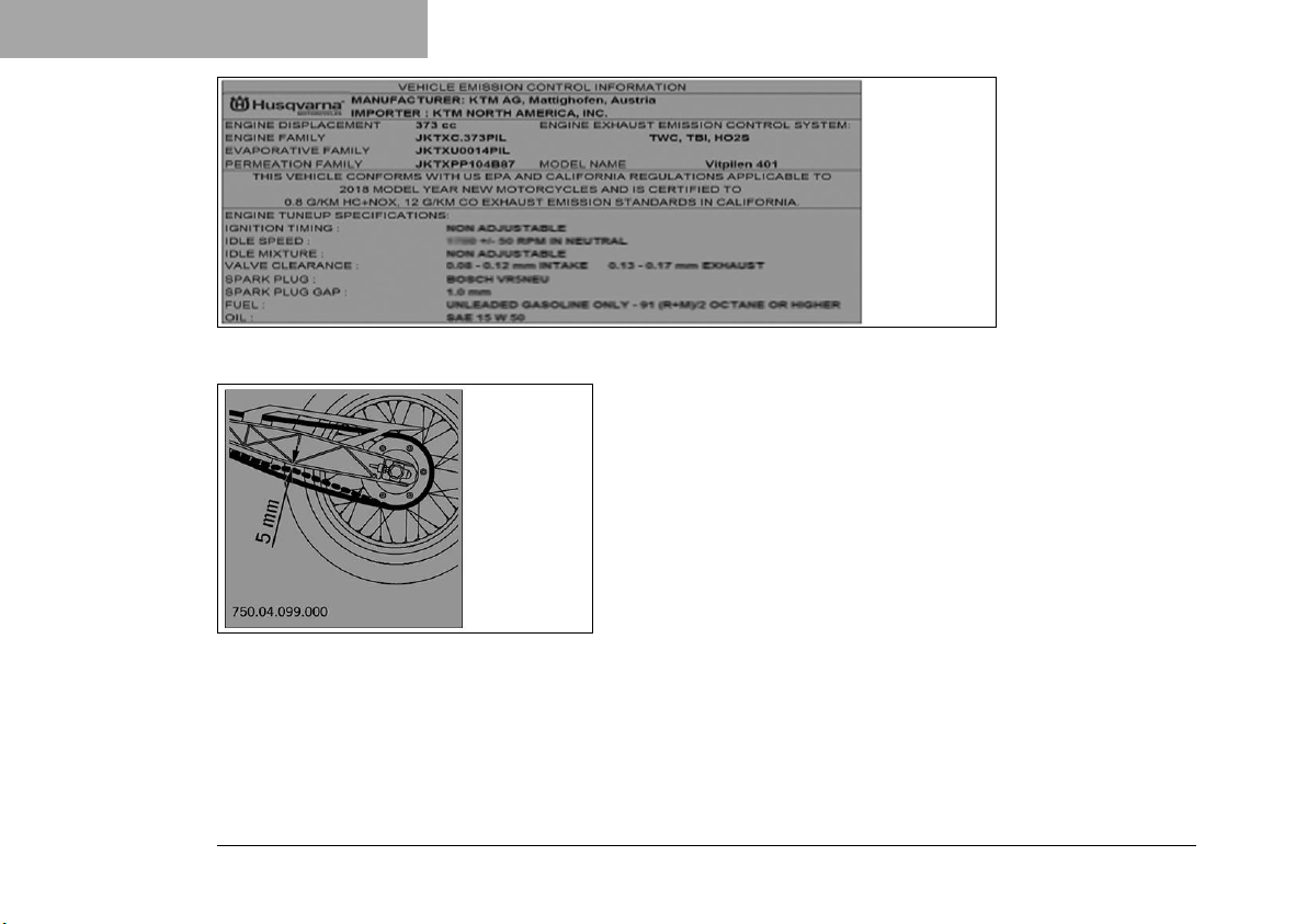
Information on emissions control
E01145-01
Information on chain tension
F01419-01
16
Page 19
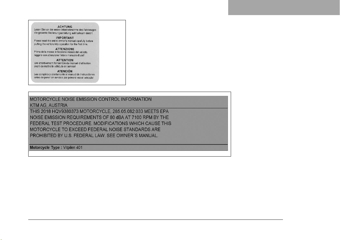
Information on noise emissions
SAFETY ADVICE 2
Information on preparations for use
F00491-01
E01147-01
17
Page 20
2 SAFETY ADVICE
Type label for USA
2.6 Consumer rights
Warranty claims should be submitted to a Husqvarna Motorcycles workshop. If you are not satisfied, please
contact:
Husqvarna Motorcycles North America, Inc., c/o KTM North America, Inc., Customer Support, 1119 Milan Ave.,
Amherst, OH 44001, USA
Phone: (440) 985–3553
www.husqvarna-motorcycles.com
Husqvarna Motorcycles North America, 1375-3 Marie-Victorin, Saint-Bruno, QC J3V-6B7, Canada
Phone: (450) 441-9222
www.husqvarna-motorcycles.com
Different rights may apply, according to national or regional legislation.
F01416-01
18
Page 21

SAFETY ADVICE 2
2.7 Operating noise warning
This product should be checked for necessary repair or replacement parts if the motorcycle noise has
increased significantly through use. Otherwise, the owner may become subject to penalties under the
applicable ordinances.
2.8 Noise emission warranty
Husqvarna Motorcycles North America, Inc. guarantees that this exhaust system satisfies all U.S. EPA Federal
noise emission standards applicable at the time of sale.
This warranty extends to the first person who buys this exhaust system for purposes other than resale, and to
all subsequent buyers.
Warranty claims should be directed to:
Husqvarna Motorcycles North America, Inc., c/o KTM North America, Inc., Customer Support, 1119 Milan Ave.,
Amherst, OH 44001, USA
Phone: (440) 985–3553
www.husqvarna-motorcycles.com
Husqvarna Motorcycles North America, 1375-3 Marie-Victorin, Saint-Bruno, QC J3V-6B7, Canada
Phone: (450) 441-9222
www.husqvarna-motorcycles.com
2.9 Reporting safety defects
If you believe that your vehicle has a defect which could cause an accident resulting in injury or death, you
should immediately inform the National Highway Traffic Safety Administration (NHTSA) in addition to notifying
Husqvarna Motorcycles North America, Inc.
19
Page 22

2 SAFETY ADVICE
If the NHTSA receives multiple similar complaints, it may open an investigation. and if it finds that a safety
defect exists in a group of vehicles, it may order a recall and remedy campaign. However, NHTSA cannot
become involved in individual problems between you, your dealer, or Husqvarna Motorcycles North America,
Inc.
You can contact the NHTSA via the toll-free “Auto Safety Hotline” on 1–888–327–4236, visit the
www.nhtsa.dot.gov website, or write to: NHTSA Headquarters, 1200 New Jersey Avenue, SE, West Building,
Washington, DC 20590. You can also obtain other information about motor vehicle safety from the hotline.
2.10 Tampering warning
Tampering with the noise control system is prohibited. Federal law prohibits the following acts or the causing
thereof:
1 The removal or rendering inoperative by any person other than for purposes of maintenance, repair, or
replacement, of any device or element of design incorporated into any new vehicle for the purpose of noise
control prior to its sale or delivery to the ultimate purchaser or while it is in use, or
2 the use of the vehicle after such device or element of design has been removed or rendered inoperative by
any person.
Among those acts presumed to constitute tampering are the acts listed below:
1 Removal or puncturing of the main silencer, baffles, header pipes or any other components which conduct
exhaust gases.
2 Removal or puncturing of parts of the intake system.
3 Lack of proper maintenance.
4 Replacing moving part of the vehicle, or parts of the exhaust or intake system, with parts other than those
specified by the manufacturer.
20
Page 23
SAFETY ADVICE 2
2.11 Safe operation
Danger
Danger of accidents A rider who is not fit to ride poses a danger to him or herself and others.
– Do not operate the vehicle if you are not fit to ride due to alcohol, drugs or medication.
– Do not operate the vehicle if you are physically or mentally impaired.
Danger
Danger of poisoning Exhaust gases are toxic and inhaling them may result in unconsciousness and
death.
– Always make sure there is sufficient ventilation when running the engine.
– Use an effective exhaust extraction system when starting or running the engine in an enclosed
space.
Warning
Danger of burns Some vehicle components become very hot when the vehicle is operated.
– Do not touch any parts such as the exhaust system, radiator, engine, shock absorber, or brake sys-
tem before the vehicle parts have cooled down.
– Let the vehicle parts cool down before you perform any work on the vehicle.
Only operate the vehicle when it is in perfect technical condition, in accordance with its intended use, and in a
safe and environmentally compatible manner.
An appropriate driver's license is needed to ride the vehicle on public roads.
21
Page 24
2 SAFETY ADVICE
Have malfunctions that impair safety immediately eliminated by an authorized Husqvarna Motorcycles workshop.
Adhere to the information and warning labels on the vehicle.
2.12 Protective clothing
Warning
Risk of injury Missing or poor protective clothing presents an increased safety risk.
– Wear appropriate protective clothing such as helmet, boots, gloves as well as trousers and a jacket
with protectors on all rides.
– Always wear protective clothing that is in good condition and meets the legal regulations.
In the interest of your own safety, Husqvarna Motorcycles recommends that you only operate the vehicle while
wearing protective clothing.
2.13 Work rules
Special tools are necessary for certain tasks. The tools are not a component of the vehicle, but can be ordered
using the number in parentheses. Example: bearing puller (15112017000)
During assembly, use new parts to replace parts which cannot be reused (e.g. self-locking screws and nuts,
seals, sealing rings, O-rings, pins, and lock washers).
In the case of certain screws, a thread locker (e.g. Loctite®) is required. Apply according to the manufacturer's
instructions.
After disassembly, clean the parts that are to be reused and check them for damage and wear. Change damaged or worn parts.
After completing a repair or service work, check the operating safety of the vehicle.
22
Page 25

SAFETY ADVICE 2
2.14 Environment
If you use your motorcycle responsibly, you can ensure that problems and conflicts do not occur. To protect
the future of the motorcycle sport, make sure that you use your motorcycle legally, be environmentally aware,
and respect the rights of others.
When disposing of used oil, other operating and auxiliary fluids, and used components, comply with the laws
and regulations of the respective country.
Because motorcycles are not subject to the EU regulations governing the disposal of used vehicles, there are
no legal regulations that pertain to the disposal of an end-of-life motorcycle. Your authorized Husqvarna Motorcycles dealer will be glad to advise you.
2.15 Owner's Manual
It is important that you read this Owner's Manual carefully and completely before making your first trip. The
Owner's Manual contains useful information and many tips on how to operate, handle, and maintain your
motorcycle. Only then will you find out how to customize the vehicle ideally for your own use and how you can
protect yourself from injury.
Keep the Owner's Manual in an accessible place to enable you to refer to it as needed.
If you would like to know more about the vehicle or have questions on the material you read, please contact an
authorized Husqvarna dealer.
The Owner's Manual is an important component of the vehicle and must be handed over to the new owner if
the vehicle is sold.
The Owner's Manual is also available for download from your authorized Husqvarna Motorcycles dealer and on
the Husqvarna Motorcycles website.
International Husqvarna Motorcycles website: www.husqvarna-motorcycles.com
23
Page 26
3 IMPORTANT NOTES
3.1 Manufacturer and implied warranty
The work prescribed in the service schedule must be carried out by an authorized Husqvarna Motorcycles
workshop only and confirmed both in the customer's Service & Warranty Booklet and in the Husqvarna Motor-
cycles Dealer.net; otherwise, all warranty claims will be void. Damage or secondary damage caused by tampering with and/or conversions on the vehicle are not covered by the warranty.
Additional information on the manufacturer or implied warranty and the procedures involved can be found in
the Service & Warranty Booklet.
3.2 Operating and auxiliary substances
Note
Environmental hazard Improper handling of fuel is a danger to the environment.
– Do not allow fuel to enter the groundwater, the soil, or the sewage system.
Use operating and auxiliary substances in accordance with the Owner's Manual and specification.
3.3 Spare parts, accessories
For your own safety, only use spare parts and accessory products that are approved and/or recommended by
Husqvarna Motorcycles and have them installed by an authorized Husqvarna Motorcycles workshop. Husqvarna Motorcycles accepts no liability for other products and any resulting damage or loss.
Certain spare parts and accessory products are specified in parentheses in the descriptions. Your authorized
Husqvarna Motorcycles dealer will be glad to advise you.
24
Page 27

IMPORTANT NOTES 3
The current Husqvarna Motorcycles accessories for your vehicle can be found on the Husqvarna Motorcycles website.
International Husqvarna Motorcycles website: www.husqvarna-motorcycles.com
3.4 Service
A prerequisite for perfect operation and prevention of premature wear is that the service, care, and tuning work
on the engine and chassis is properly carried out as described in the Owner's Manual. Incorrect adjustment
and tuning of the engine and chassis can lead to damage and breakage of components.
Use of the vehicle under difficult conditions, such in rain, high heat or with a heavy load, can lead to considerably more rapid wear of components such as the drive train, brake system, or suspension components. For this
reason, it may be necessary to inspect or replace parts before the next scheduled service.
It is imperative that you adhere to the stipulated run-in times and service intervals. If you observe these exactly,
you will ensure a much longer service life for your motorcycle.
3.5 Figures
The figures contained in the manual may depict special equipment.
In the interest of clarity, some components may be shown disassembled or may not be shown at all. It is not
always necessary to disassemble the component to perform the activity in question. Please follow the instructions in the text.
3.6 Customer service
Your authorized Husqvarna Motorcycles dealer will be happy to answer any questions you may have regarding
your vehicle and Husqvarna Motorcycles.
25
Page 28

3 IMPORTANT NOTES
A list of authorized Husqvarna Motorcycles dealers can be found on the Husqvarna Motorcycles website.
International Husqvarna Motorcycles website: www.husqvarna-motorcycles.com
26
Page 29

IMPORTANT NOTES 3
27
Page 30
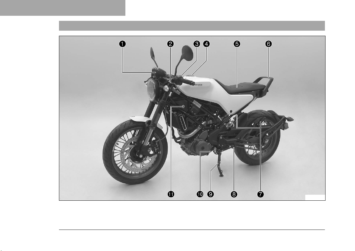
4 VIEW OF VEHICLE
4.1 View of vehicle, front left (example)
28
E01095-10
Page 31

Combination instrument ( p. 52)
1
Clutch lever ( p. 35)
2
High beam flasher button ( p. 36)
3
Light switch ( p. 37)
3
Turn signal switch ( p. 37)
3
Horn button ( p. 38)
3
Filler cap
4
Seat
5
Grab handle ( p. 45)
6
Passenger foot pegs ( p. 45)
7
Shift lever ( p. 46)
8
Side stand ( p. 47)
9
Engine number ( p. 33)
bk
Seat lock ( p. 44)
bl
VIEW OF VEHICLE 4
29
Page 32
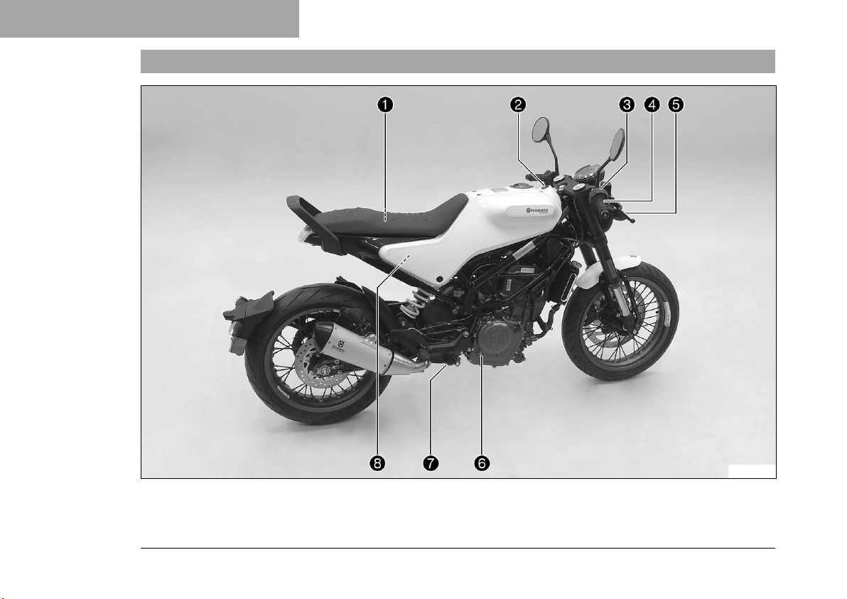
4 VIEW OF VEHICLE
4.2 View of vehicle, rear right (example)
30
E01094-10
Page 33

Tool set ( p. 44)
1
Ignition/steering lock ( p. 39)
2
Emergency OFF switch ( p. 38)
3
Electric starter button ( p. 39)
3
Throttle grip ( p. 36)
4
Hand brake lever ( p. 35)
5
Level viewer, engine oil
6
Foot brake lever ( p. 47)
7
Compensating tank for coolant
8
VIEW OF VEHICLE 4
31
Page 34
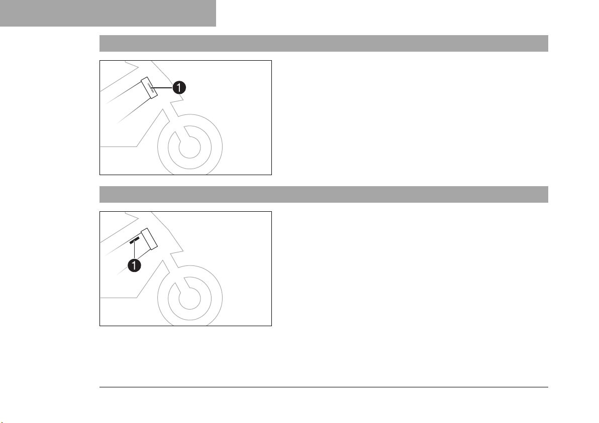
5 SERIAL NUMBERS
0011
0011
5.1 Chassis number
5.2 Type label
The chassis number1is stamped on the right side of the steering head.
402408-10
The USA type label1is on the right of the frame behind the
steering head.
402174-10
32
Page 35
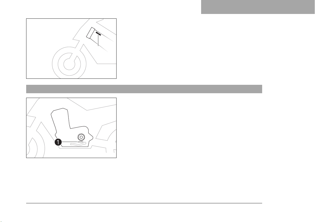
00110022
5.3 Engine number
SERIAL NUMBERS 5
The Canada type label2is on the left of the frame behind the
steering head.
F01412-01
The engine number1is stamped on the left side of the engine
under the engine sprocket.
402486-10
33
Page 36
5 SERIAL NUMBERS
Code number
5.4 Key number
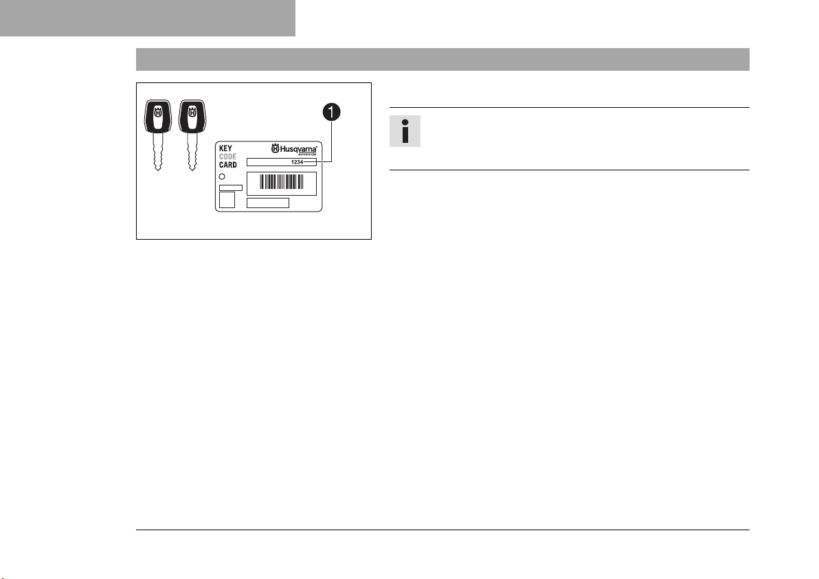
The key number1can be found on the KEYCODECARD.
Info
You need the key number to order a spare key. Keep
the KEYCODECARD in a safe place.
F01413-10
34
Page 37
6.1 Clutch lever
6.2 Hand brake lever
CONTROLS 6
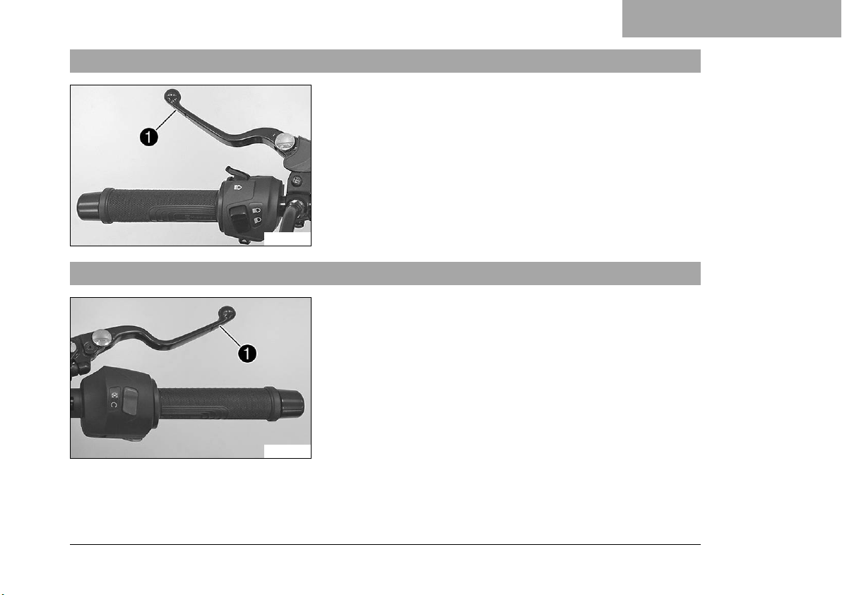
The clutch lever1is fitted on the left side of the handlebar.
F01351-10
The hand brake lever1is fitted on the right side of the handlebar.
The front brake is engaged using the hand brake lever.
F01352-10
35
Page 38
6 CONTROLS
6.3 Throttle grip
6.4 Switches on the left side of the handlebar
6.4.1 High beam flasher button
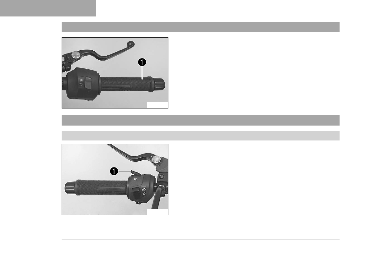
The throttle grip1is fitted on the right side of the handlebar.
F01352-11
The high beam flasher button1is fitted on the left side of the
handlebar.
Possible states
• High beam flasher button in neutral position
• High beam flasher button pressed – In this position, the
headlight flasher (high beam) is actuated.
36
F01366-10
Page 39
6.4.2 Light switch
6.4.3 Turn signal switch
F01354-10
F01353-10
CONTROLS 6
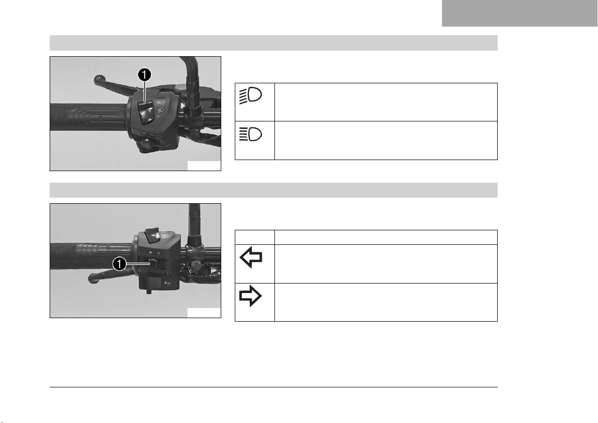
Light switch1is fitted on the left side of the handlebar.
Possible states
Low beam on – The light switch is turned downward. In this position, the low beam and tail light are
switched on.
High beam on – The light switch is turned upwards.
In this position, the low beam, the high beam and the
tail light are switched on.
Turn signal switch1is fitted on the left side of the handlebar.
Possible states
Turn signal off
Left turn signal, on – Turn signal switch pressed to
the left. The turn signal switch returns automatically
to the central position after use.
Right turn signal, on – Turn signal switch pressed to
the right. The turn signal switch returns automatically
to the central position after use.
To switch off the turn signal, press the turn signal switch towards
the switch case.
37
Page 40
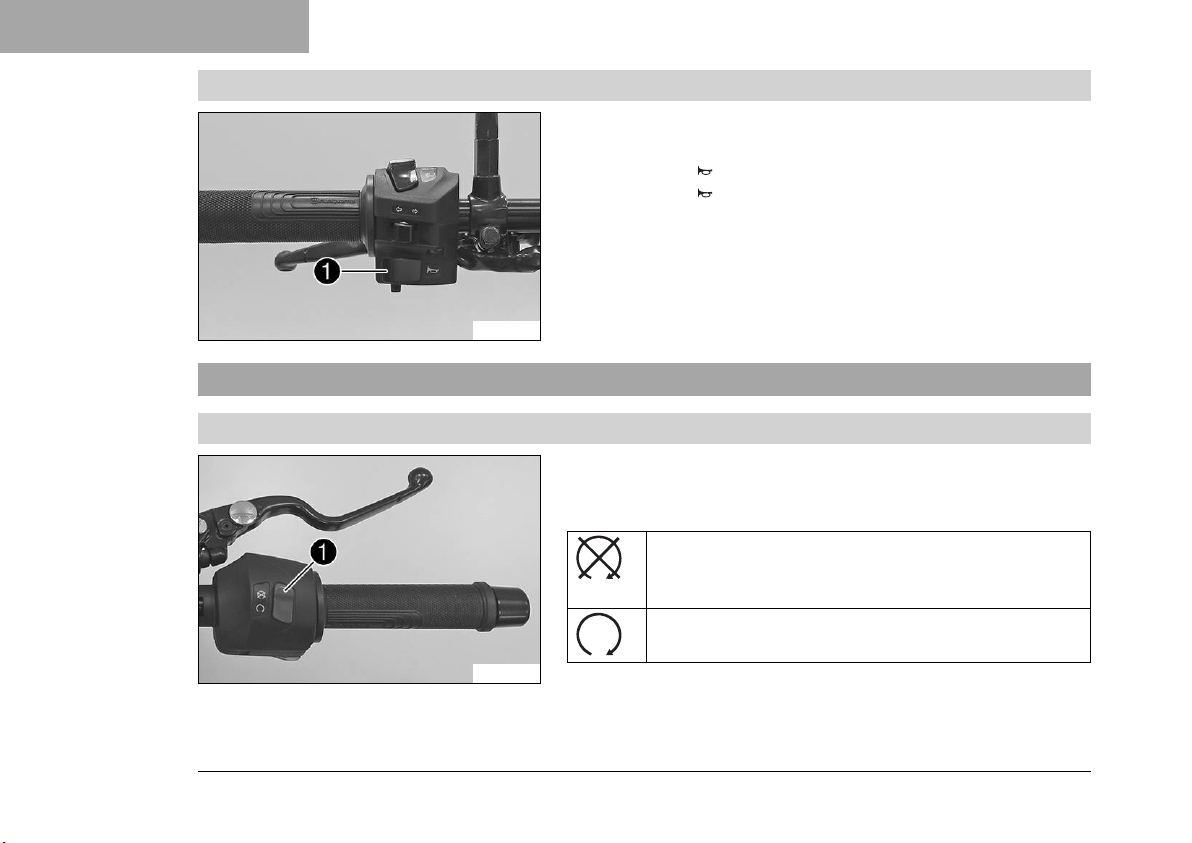
6 CONTROLS
6.4.4 Horn button
6.5 Switches on the right side of the handlebar
6.5.1 Emergency OFF switch
The horn button1is fitted on the left side of the handlebar.
Possible states
• Horn button in neutral position
• Horn button pressed – The horn is operated in this position.
F01353-11
The emergency OFF switch1is fitted on the right side of the
handlebar.
Possible states
Emergency OFF switch off – In this position, the ignition circuit is interrupted, a running engine stops,
and a non-running engine cannot be started.
Emergency OFF switch on – This position is required
for operation; the ignition circuit is closed.
F01352-12
38
Page 41
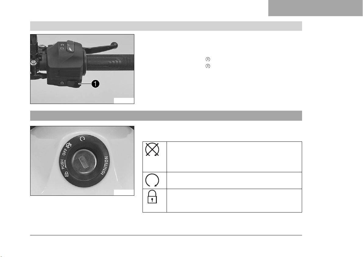
6.5.2 Electric starter button
F01355-10
6.6 Ignition/steering lock
F01356-01
CONTROLS 6
The electric starter button1is fitted on the right side of the
handlebar.
Possible states
• Electric starter button in basic position
• Electric starter button pressed – In this position, the electric starter is actuated.
The ignition/steering lock is in front of the upper triple clamp.
Possible states
Ignition off OFF – In this position, the ignition circuit
is interrupted, a running engine stops, and a nonrunning engine will not start. The ignition key can be
removed.
Ignition on – In this position, the ignition circuit is
closed and the engine can be started.
Steering locked – In this position, the ignition circuit
is interrupted and the steering locked. The ignition
key can be removed.
39
Page 42
6 CONTROLS
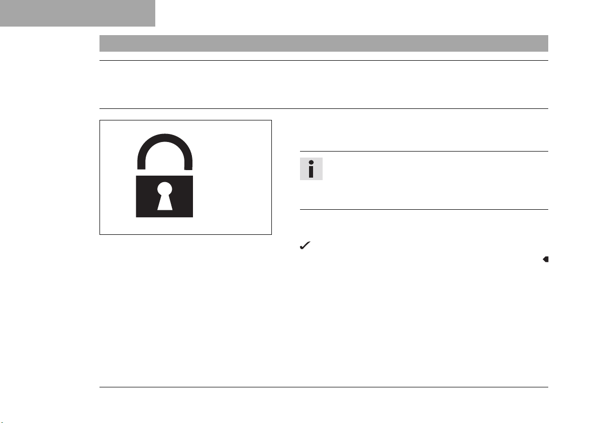
6.7 Locking the steering
Note
Danger of damage The parked vehicle can roll away or fall over.
– Park the vehicle on a firm and level surface.
– Park the vehicle.
– Turn the handlebar all the way to the left.
Info
The steering can also be locked by turning it fully to
the right. With the steering turned to the right, the
vehicle is in a less slanted position.
40
400732-01
– Insert the key into the ignition/steering lock, press in, and turn
to the left. Remove the key.
Steering is no longer possible.
Page 43
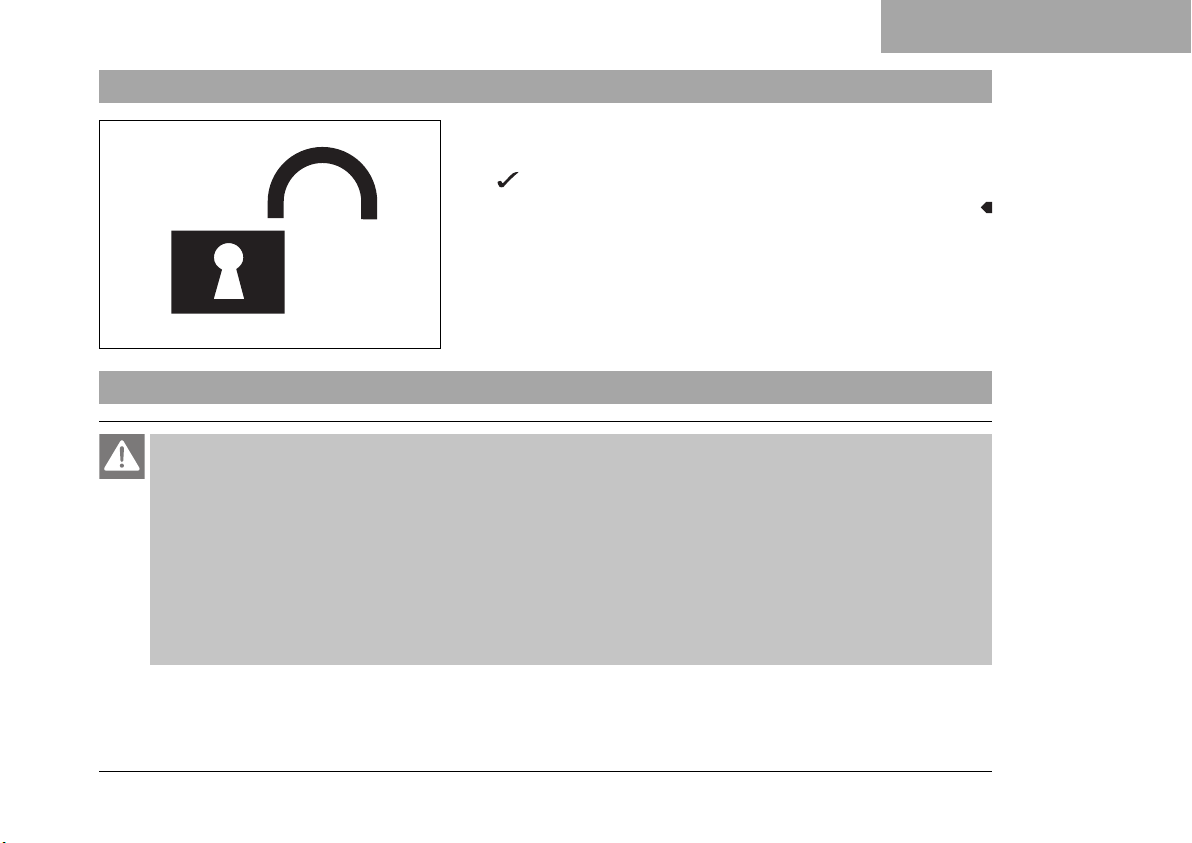
6.8 Unlocking the steering
– Insert the key into the ignition/handlebar lock, press in, and
turn to the right. Remove the key.
You can now steer the bike again.
400731-01
6.9 Opening the filler cap
Danger
Fire hazard Fuel is highly flammable.
The fuel in the fuel tank expands when warm and can escape if overfilled.
– Do not refuel the vehicle in the vicinity of open flames or lit cigarettes.
– Switch off the engine for refueling.
– Make sure that no fuel is spilled; particularly not on hot parts of the vehicle.
– If any fuel is spilled, wipe it off immediately.
– Observe the specifications for refueling.
CONTROLS 6
41
Page 44
6 CONTROLS
Warning
Danger of poisoning Fuel is poisonous and a health hazard.
– Avoid skin, eye and clothing contact with fuel.
– Immediately consult a doctor if you swallow fuel.
– Do not inhale fuel vapors.
– In case of skin contact, rinse the affected area with plenty of water.
– Rinse the eyes thoroughly with water, and consult a doctor in case of fuel contact with the eyes.
– Change your clothing in case of fuel spills on them.
– Keep fuels correctly in a suitable canister, and out of the reach of children.
Note
Environmental hazard Improper handling of fuel is a danger to the environment.
– Do not allow fuel to enter the groundwater, the soil, or the sewage system.
F01367-10
–
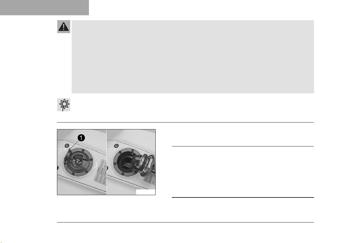
Lift cover1of the filler cap and insert the ignition key in the
lock.
Note
Danger of damage The ignition key may break if over-
loaded.
Damaged ignition keys must be replaced.
– Push down on the filler cap to take pressure off the igni-
tion key.
42
– Turn the ignition key 90° clockwise.
Page 45
6.10 Closing the filler cap
F01368-01
CONTROLS 6
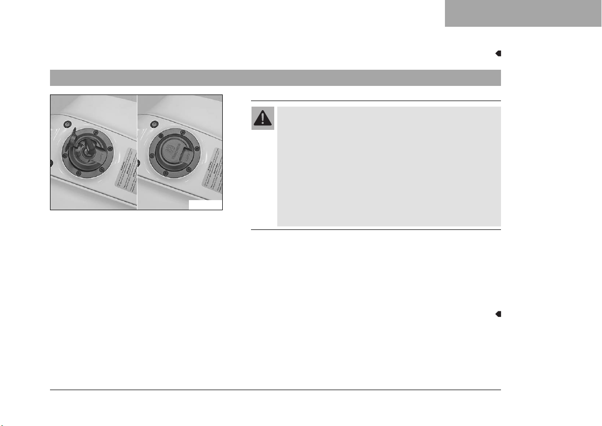
– Open the filler cap.
Warning
Fire hazard Fuel is highly flammable, toxic and a
health hazard.
– Check the filler cap is locked correctly after clos-
ing.
– Change your clothing in case of fuel spills on
them.
– Rinse the affected area immediately with plenty of
water in the event of contact with the skin.
– Fold down the filler cap.
– Turn the ignition key 90° clockwise.
– Push down the filler cap and turn the ignition key counter-
clockwise until the tank lock engages.
– Remove the ignition key and close the cover.
43
Page 46
6 CONTROLS
6.11 Seat lock
6.12 Tool set
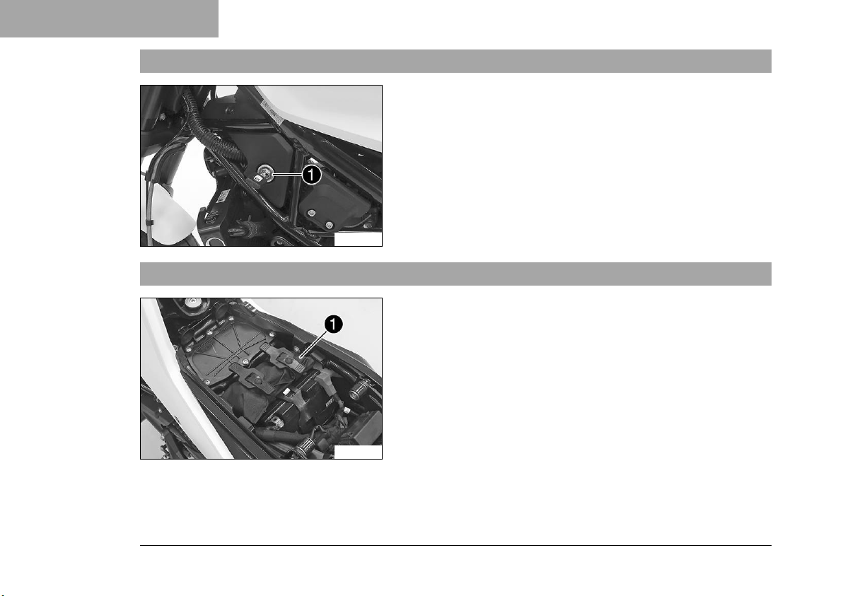
The seat lock1is located at the front left below the fuel tank.
The seat lock can be unlocked using the ignition key.
F01357-10
The tool set1is located under the seat.
44
F01358-10
Page 47
6.13 Grab handle
F01359-10
6.14 Passenger foot pegs
CONTROLS 6
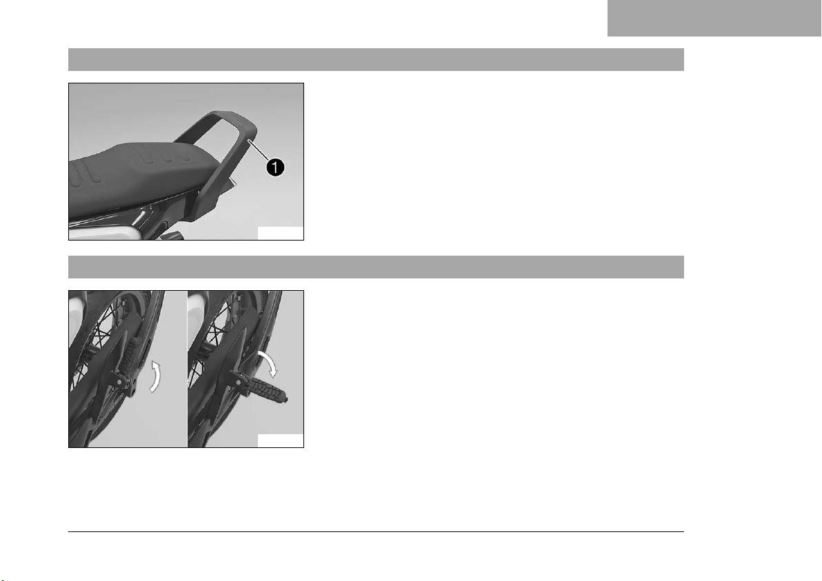
The grab handle1is used for maneuvering the motorcycle.
If you carry a passenger, the passenger can hold onto the grab
handles during the trip.
The passenger foot pegs can be folded up and down.
Possible states
• Passenger foot pegs folded up – For operation without a
passenger.
• Passenger foot pegs folded down – For operation with a
passenger.
F01365-10
45
Page 48
6 CONTROLS
6.15 Shift lever
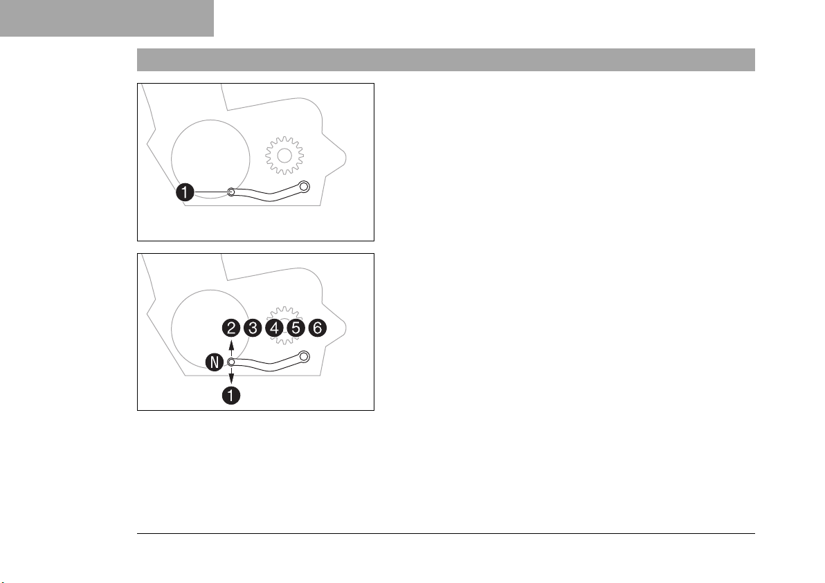
Shift lever1is mounted on the left side of the engine.
401950-10
The gear positions can be seen in the photograph.
The neutral or idle position is between the first and second gears.
401950-11
46
Page 49
6.16 Foot brake lever
6.17 Side stand
CONTROLS 6
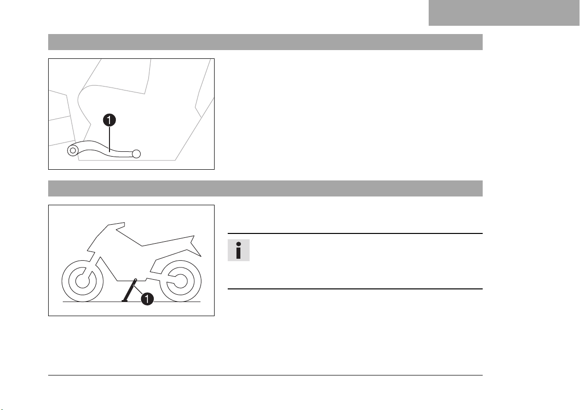
Foot brake lever1is located in front of the right footrest.
The foot brake lever is used to activate the rear brake.
402177-10
Side stand1is located on the left of the vehicle.
The side stand is used for parking the motorcycle.
Info
The side stand must be folded up during motorcycle use.
Side stand is coupled with the safety start system; follow
the riding instructions.
402029-10
Possible states
• Side stand folded out – The vehicle can be supported on the
side stand. The safety start system is enabled.
47
Page 50

6 CONTROLS
• Side stand folded in – This position is mandatory when riding the motorcycle. The safety start system is disabled.
48
Page 51
7.1 Adjusting the basic position of the hand brake lever
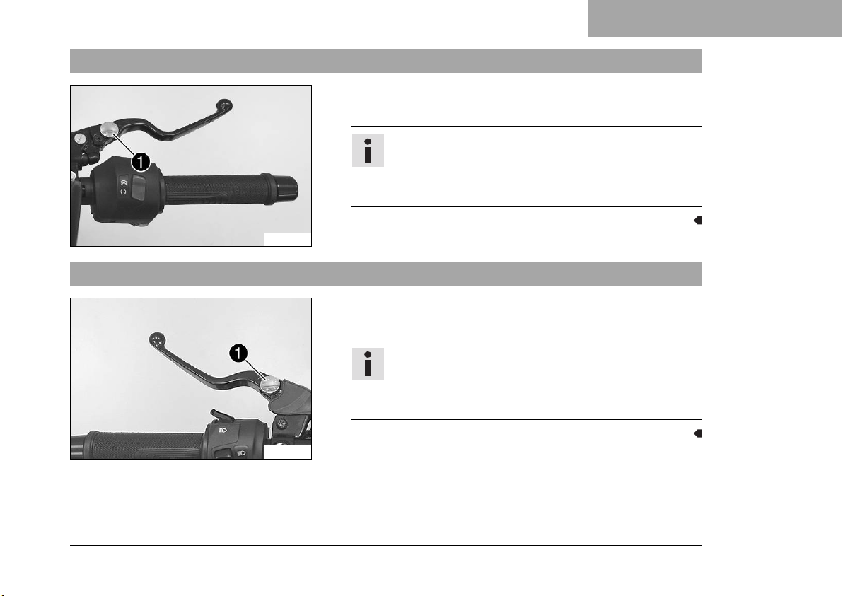
– Adjust the basic position of the hand brake lever to your hand
size by turning adjusting wheel1.
Info
Push the hand brake lever forward and turn the
adjusting wheel.
Do not make any adjustments while riding.
E01099-10
7.2 Adjusting the basic position of the clutch lever
– Adjust the basic position of the clutch lever to your hand size
by turning adjusting wheel1.
Info
Push the clutch lever forward and turn the adjusting
wheel.
Do not make any adjustments while riding.
ERGONOMICS 7
E01116-11
49
Page 52
7 ERGONOMICS
7.3 Adjusting the shift lever
Info
The adjustment range of the shift lever is limited.
E01143-10
–
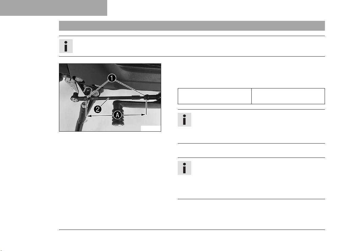
Loosen nuts1.
–
Adjust the shift lever by turning shift rod2.
Guideline
Shift rod adjustment rangeA128 … 142 mm (5.04 …
5.59 in)
Info
Make the same adjustments on both sides.
At least five screw threads must be screwed into the
seating.
–
Tighten nuts1.
Info
After the nuts have been tightened, the bearings of
the shift rod must be central and aligned identically to
each other in order to ensure freedom of movement in
the bearing shells.
50
Page 53

ERGONOMICS 7
– Check the shift lever to ensure it is functioning properly and
can move freely.
51
Page 54
8 COMBINATION INSTRUMENT
8.1 Combination instrument
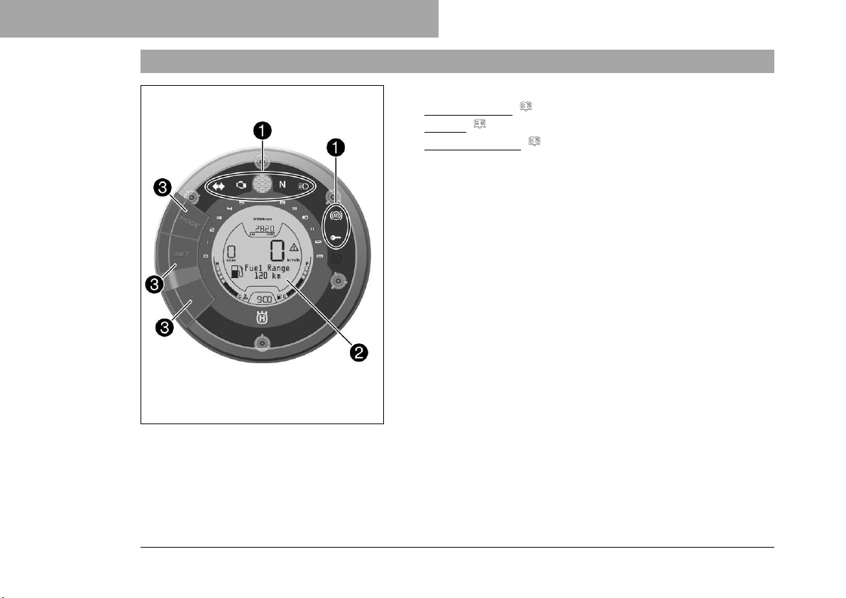
The combination instrument is attached in front of the handlebar.
1
2
3
F01369-10
Indicator lamps ( p. 59)
Display ( p. 63)
Function buttons ( p. 66)
52
Page 55
8.2 Activation and test
COMBINATION INSTRUMENT 8
Activation
The combination instrument is activated when the ignition is
switched on.
Info
The brightness of the displays is controlled by a brightness sensor in the combination instrument.
Test
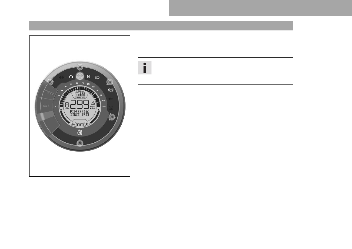
When the ignition is switched on, all indicator lamps light up
briefly except for the turn signal indicator lamp and immobilizer
indicator lamp.
The segments of the tachometer and the gear display light up
and switch off in sequence.
The speedometer counts from 0 to 299 and back.
The remaining display segments of the display light up briefly.
The PIONEERING SINCE 1903 logo appears on the display.
The display then changes to the last selected mode.
F01370-01
53
Page 56
8 COMBINATION INSTRUMENT
8.3 Warning notes
Info
The malfunction indicator lamp always lights up as long as
the engine is not running. If the engine is running and the
malfunction indicator lamp lights up, stop (taking care not
to endanger yourself or other road users in the process)
and contact an authorized Husqvarna Motorcycles workshop.
The ABS warning lamp lights up so long as a speed of
approx. 6 km/h (approx. 4 mph) or more has been
reached.
Info
All existing warning notes are displayed on the Info display until these are no longer active.
As soon as an error occurs, the relevant indicator lamps
light up to signal that an indication/warning note for the
operating safety has been detected.
As soon as several warnings have been detected, the
general warning symbol flashes additionally on the display.
54
Page 57
F01389-01
F01404-01
COMBINATION INSTRUMENT 8
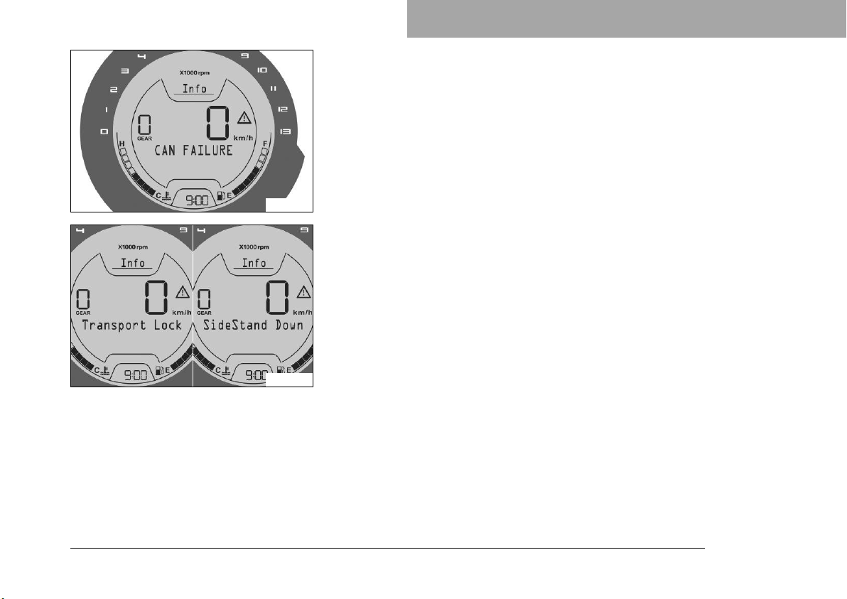
If an error has occurred in the CAN bus, various warning notes
appear on the display:
CAN FAILURE, CAN ABS FAILURE, CAN EMS FAILURE
and CAN HLU FAILURE can occur.
Transport Lock appears on the display if transport mode is activated.
SideStand Down appears on the display if the side stand is
folded down.
55
Page 58
8 COMBINATION INSTRUMENT
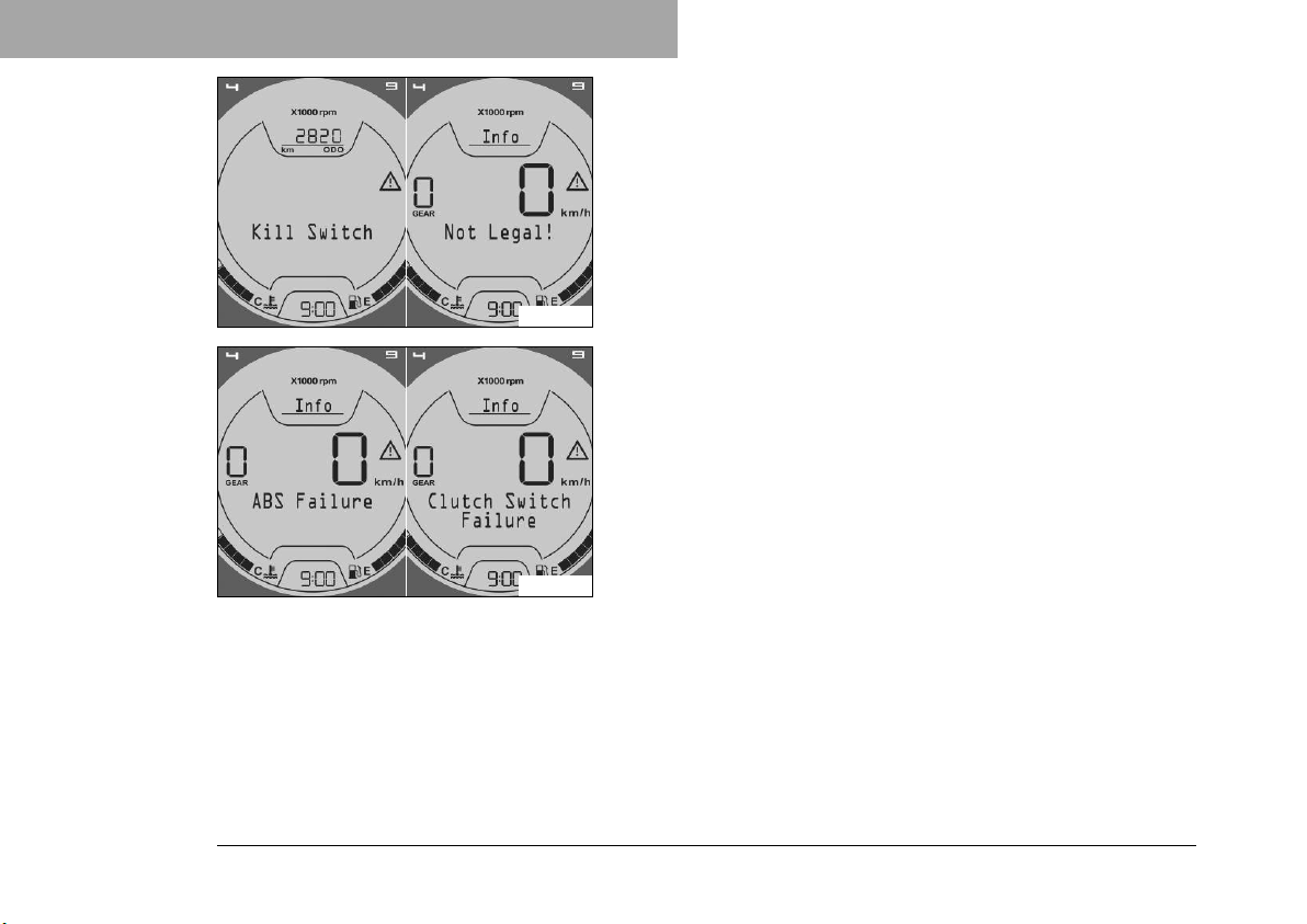
Kill Switch appears on the display if the emergency off switch is
pressed.
Not Legal! appears on the display if the approval for road use is
invalidated by modifications.
F01405-01
ABS Failure appears on the display if the ABS is no longer
active.
Clutch Switch Failure appears on the display if the clutch switch
is faulty.
F01406-01
56
Page 59
F01407-01
F01408-01
COMBINATION INSTRUMENT 8
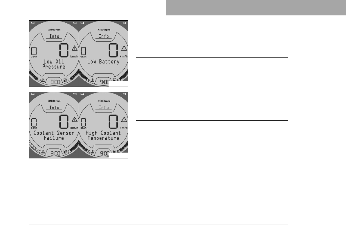
Low Oil Pressure appears on the display if the oil pressure is
too low.
Low Battery appears on the display if the battery voltage falls
below the specified value.
Battery voltage ≤ 10.5 V
Coolant Sensor Failure appears on the display if the coolant
temperature sensor is faulty.
High Coolant Temperature appears on the display if the coolant
temperature rises above the specified value.
Coolant temperature > 115 °C (> 239 °F)
57
Page 60
8 COMBINATION INSTRUMENT
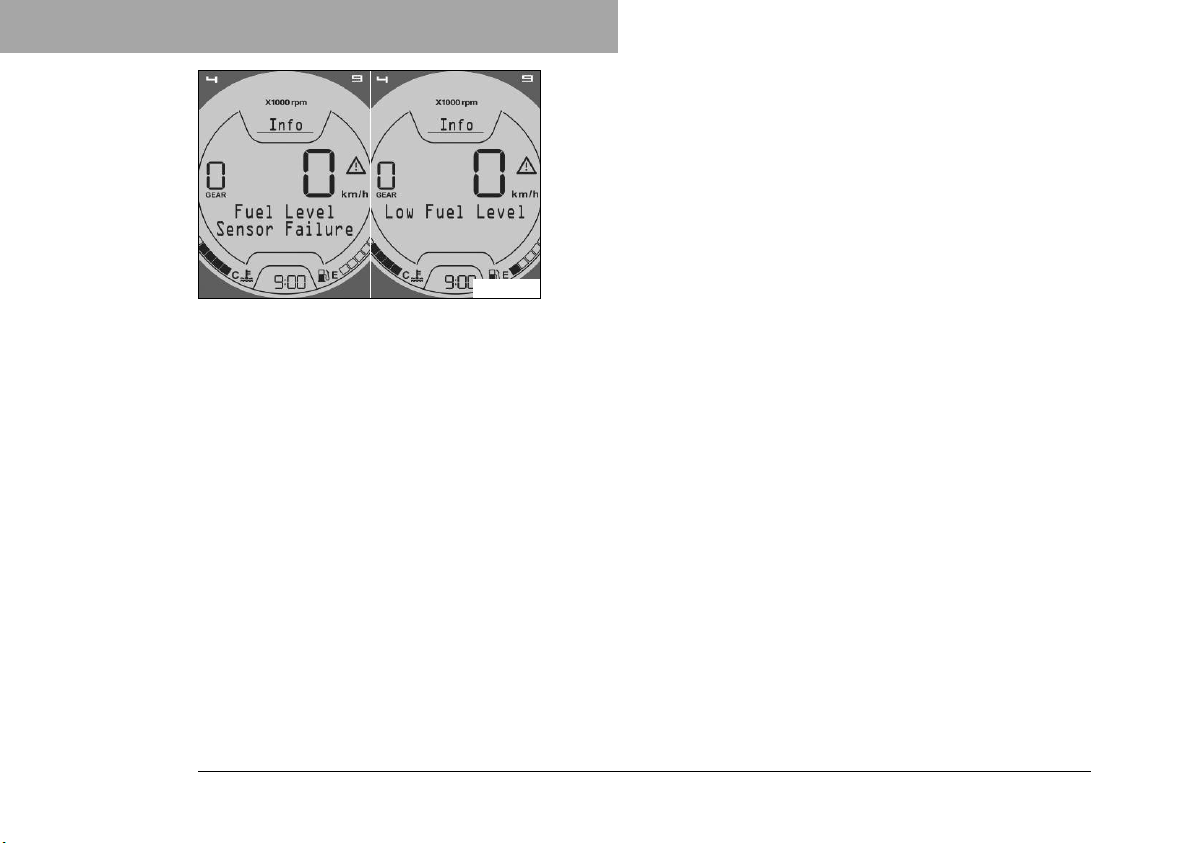
Fuel Level Sensor Failure appears on the display if the fuel level
indicator is faulty.
Low Fuel Level appears on the display if the fuel level reaches
the reserve mark.
F01409-01
58
Page 61
8.4 Indicator lamps
COMBINATION INSTRUMENT 8
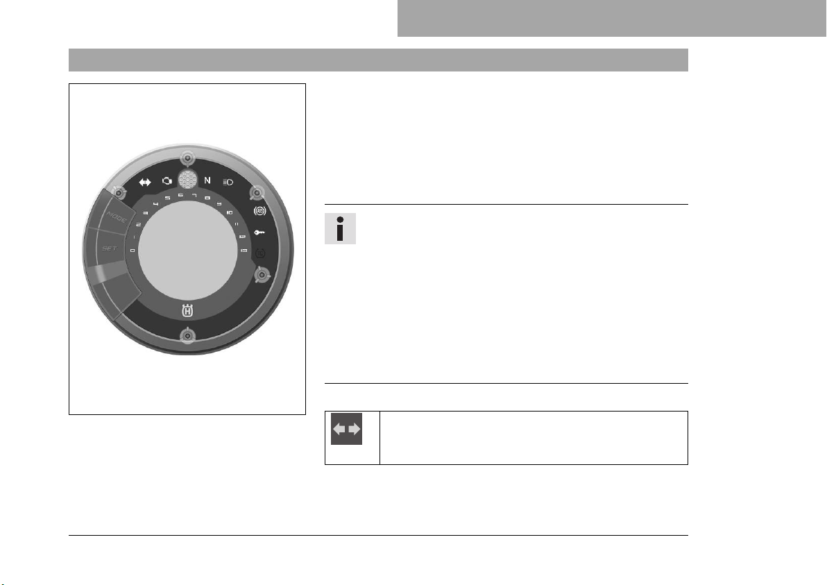
The indicator lamps offer additional information about the operating state of the motorcycle.
When the ignition is switched on, all indicator lamps light up
briefly except for the turn signal indicator lamp and immobilizer
indicator lamp.
As soon as several warnings have been detected, the general
warning symbol flashes additionally on the display.
Info
The malfunction indicator lamp always lights up as long as
the engine is not running. If the engine is running and the
malfunction indicator lamp lights up, stop (taking care not
to endanger yourself or other road users in the process)
and contact an authorized Husqvarna Motorcycles workshop.
The ABS warning lamp lights up so long as a speed of
approx. 6 km/h (approx. 4 mph) or more has been
reached.
F01372-01
Possible states
The turn signal indicator lamp flashes green simultaneously with the turn signal – The turn signal is
switched on.
59
Page 62
8 COMBINATION INSTRUMENT
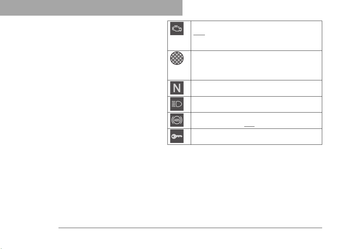
Malfunction indicator lamp lights up yellow – The
OBD has detected an error in the vehicle electronics. Come safely to a halt, and contact an authorized
Husqvarna Motorcycles workshop.
The shift warning lights up/flashes red – The shift
warning light flashes red when the set shift speed
RPM1 is reached. The shift warning light lights up
red when the set shift speed RPM2 is reached.
The idle indicator lamp lights up green – The transmission is in idle.
The high beam indicator lamp lights up blue – The
high beam is switched on.
ABS warning lamp lights up yellow – Status or error
messages relating to ABS.
The immobilizer indicator lamp lights up red – Status
or error message for immobilizer.
60
Page 63
8.5 Shift warning light
F01411-10
COMBINATION INSTRUMENT 8
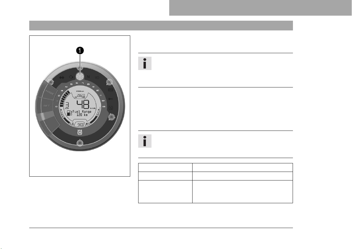
The shift warning light1is located in the center above the display.
Info
The shift warning light can be configured in the Trip 1 display and Trip 2 display by keeping the MODE button
pressed.
The shift warning light is always active during the running-in
phase (up to 1,000 km / 621 miles). The shift warning light can
only be deactivated, and the values for RPM1 and RPM2 can
only be adjusted after this. The shift warning light flashes red at
RPM1 and the shift warning light lights up red at RPM2.
Info
In sixth-gear, the shift warning light is deactivated when
the engine is warm after the first service.
Coolant temperature ≤ 35 °C (≤ 95 °F)
ODO < 1,000 km (< 620 mi)
The shift warning
light always lights
up at
6,500 rpm
61
Page 64
8 COMBINATION INSTRUMENT
Coolant temperature > 35 °C (> 95 °F)
ODO > 1,000 km (> 620 mi)
RPM1 shift warning
light
RPM2 shift warning
light
flashes
lights up
62
Page 65
8.6 Display
COMBINATION INSTRUMENT 8
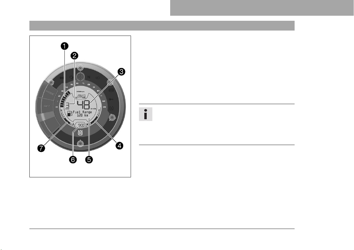
The tachometer1shows the engine speed in revolutions per
minute.
The gear display2shows the engaged gear.
Speed3is shown in kilometers per hour km/h or in miles per
hour mph.
The fuel level display is displayed in the4area.
The display5shows additional information.
The time appears in area6.
The coolant temperature display appears in area7.
Info
The time must be reset if the battery was disconnected
from the vehicle or the fuse was removed.
The brightness of the displays is controlled by a brightness sensor in the combination instrument.
F01373-10
63
Page 66
8 COMBINATION INSTRUMENT
8.7 Fuel level display
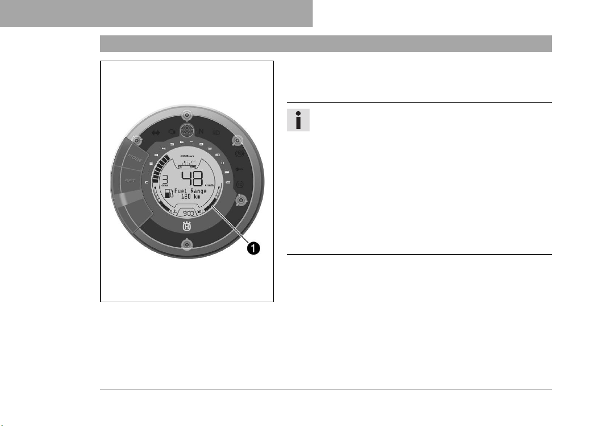
The fuel tank contents are shown in area1of the display.
The fuel level indicator consists of bars. The more bars are lit, the
more fuel is in the fuel tank.
F01374-10
Info
If the fuel level is getting low, the warning
note Low Fuel Level will also appear on the display.
The fuel level is displayed with a slight delay to prevent
the indicator from constantly moving while riding.
The fuel level display is not updated while the side stand
is folded out or the emergency off switch is switched off.
Once the side stand is folded up and emergency OFF
switch is switched on, the fuel level display is next
updated after 2 minutes.
The fuel level display flashes if the combination instrument
does not receive a signal from the fuel level sensor.
64
Page 67
8.8 Coolant temperature indicator
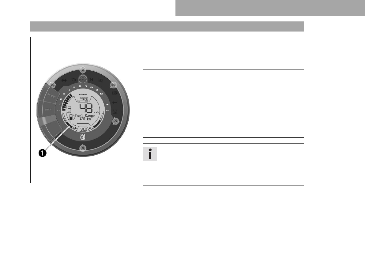
The coolant temperature display is shown in segment1of the
display.
The coolant temperature indicator consists of bars. The more
bars that light up, the hotter the coolant.
Note
Engine failure Overheating damages the engine.
– If the coolant temperature warning is displayed, stop imme-
– Allow the engine and cooling system to cool down.
– Check and, if necessary, correct the coolant level on the
F01374-11
COMBINATION INSTRUMENT 8
diately and take care not to endanger yourself or other traffic
participants in the process.
cooling system while it is in a cooled state.
Info
When all bars light up, the warning
note High Coolant Temperatureappears on the display.
If the cooling system overheats, the maximum engine
speed is limited.
Possible states
• The engine is cold – Up to three bars light up.
• Engine warm – Four bars light up.
65
Page 68
8 COMBINATION INSTRUMENT
• Engine hot – Five to eight bars light up.
• Engine very hot – All eight bars light up.
8.9 Function buttons
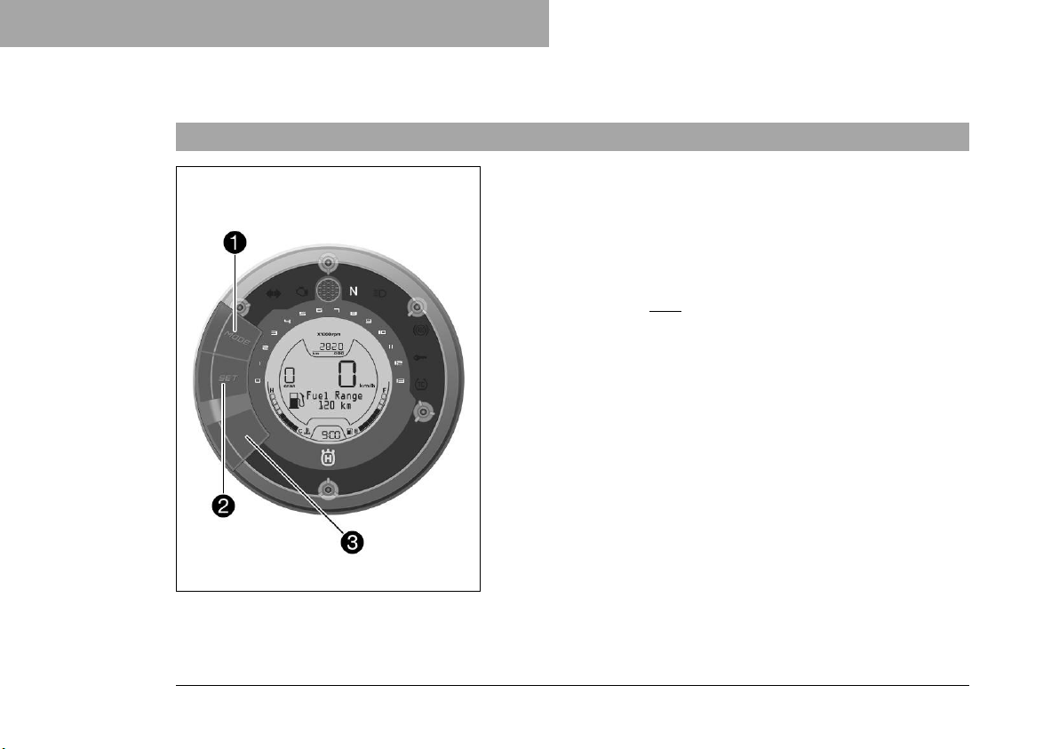
Press the MODE button1to change display modes.
Possible display modes are Info, total distance traveled (ODO),
distance 1 (TRIP 1) and distance 2 (TRIP 2).
Press the SET button2to change menus within a display
mode.
Keeping the3button and MODE button1pressed simultaneously enables the ABS to be activated.
66
F01371-10
Page 69
8.10 Info display
F01387-01
COMBINATION INSTRUMENT 8
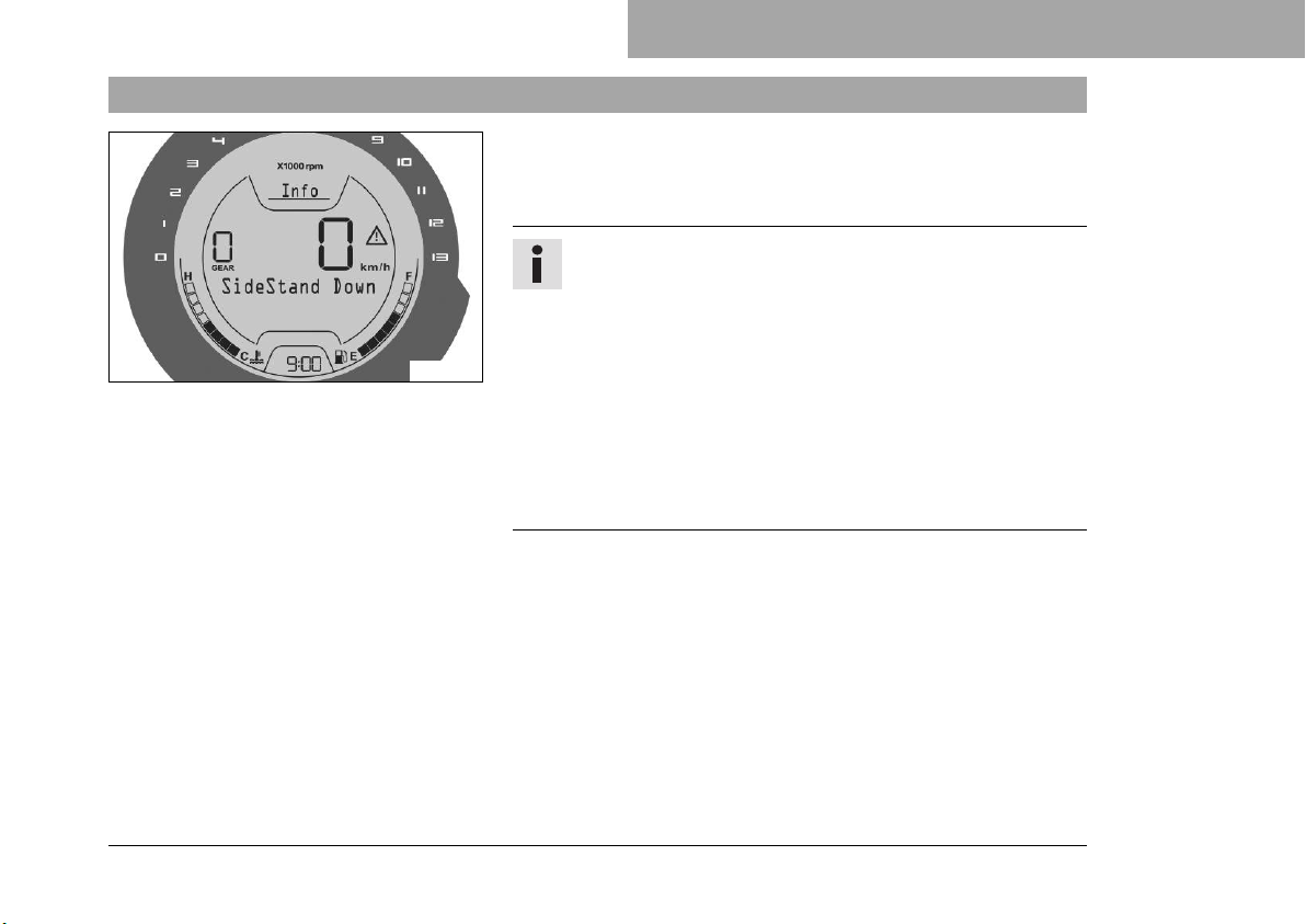
– Press the MODE button briefly and repeatedly until Info
appears on the display.
Info shows messages or warnings that have occurred.
Info
The Info display is only shown if a message or warning is
pending.
The warnings that have occurred are saved in the
Info display until these are no longer active.
All warnings that have occurred are shown automatically
in succession on the Info display.
Press the SET button briefly to change to the next warning note in the display.
Press the MODE button briefly to change to the next display mode in the display.
67
Page 70
8 COMBINATION INSTRUMENT
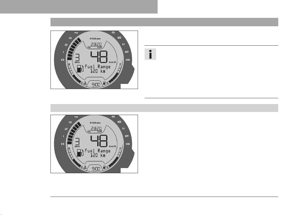
8.11 ODO display
Press the MODE button briefly and repeatedly until ODO
appears on the display.
F01375-01
8.11.1 Fuel Range
– Press the MODE button briefly and repeatedly until ODO
– Press the SET button briefly and repeatedly until the desired
The Fuel Range menu is identical on the ODO display, the
Trip 1 display and the Trip 2 display.
The range is shown in this menu.
Info
ODO shows the total distance covered.
This value is retained, even if the battery is disconnected
from the vehicle or the fuse blows.
Press the SET button briefly to change to the next menu
in the display.
Press the MODE button briefly to change to the next display mode in the display.
appears on the display.
menu appears.
68
F01375-01
Page 71
COMBINATION INSTRUMENT 8
Info
The range depends on the average fuel consumption and
the fuel quantity in the fuel tank.
The range is displayed after several 100 meters of travel
after the ignition is switched on.
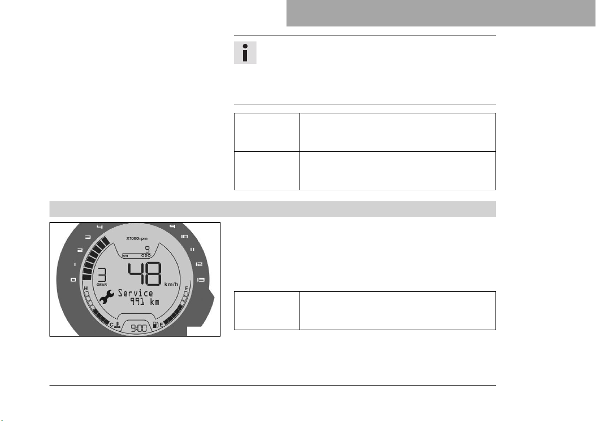
8.11.2 Service
F01376-01
Press the
SET button
briefly.
Press the
MODE button briefly.
– Press the MODE button briefly and repeatedly until ODO
appears on the display.
– Press the SET button briefly and repeatedly until the desired
menu appears.
This menu shows the distance to the next service.
Press the
SET button
briefly.
Next menu on the display
Next display mode on the display
Next menu on the display
69
Page 72
8 COMBINATION INSTRUMENT
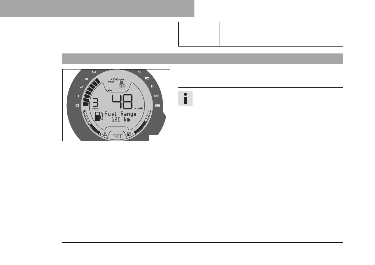
8.12 TRIP 1 display
F01379-01
Press the
MODE button briefly.
Press the MODE button briefly and repeatedly until TRIP 1
appears on the display.
Next display mode on the display
Info
TRIP 1 shows the distance since the last reset, such as
between two refueling stops. TRIP 1 is always running
and counts up to 9999.9.
Press the SET button briefly to change to the next menu
in the display.
Press the MODE button briefly to change to the next display mode in the display.
70
Page 73
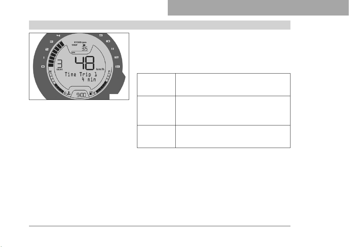
8.12.1 Time Trip 1
COMBINATION INSTRUMENT 8
– Press the MODE button briefly and repeatedly until TRIP 1
appears on the display.
– Press the SET button briefly and repeatedly until the desired
menu appears.
Riding time 1 based on TRIP 1 is shown in this menu.
F01380-01
Press the
SET button
briefly.
Press the
SET button
for 3 seconds.
Press the
MODE button briefly.
Next menu on the display
Display of TRIP 1 is reset
Next display mode on the display
71
Page 74
8 COMBINATION INSTRUMENT
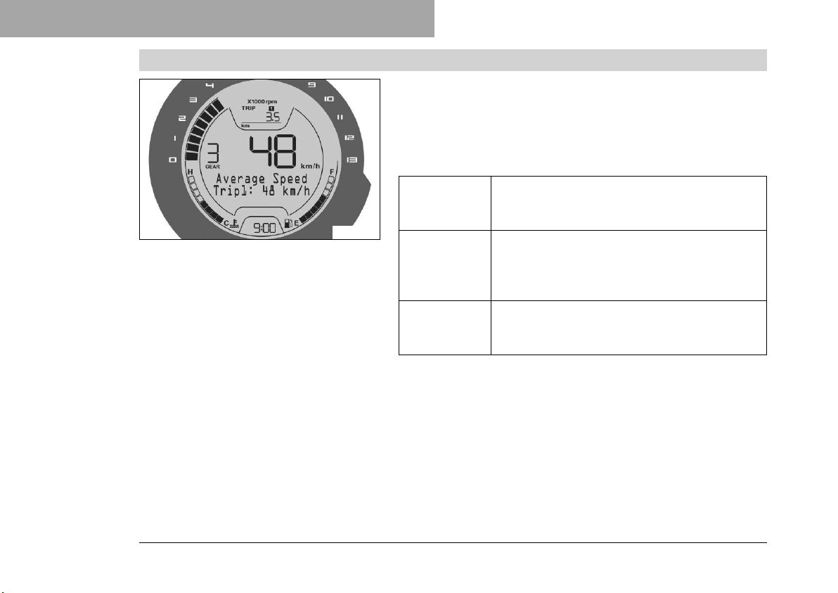
8.12.2 Average Speed Trip1
– Press the MODE button briefly and repeatedly until TRIP 1
– Press the SET button briefly and repeatedly until the desired
Average speed 1 based on TRIP 1 is shown in this menu.
appears on the display.
menu appears.
72
F01381-01
Press the
SET button
briefly.
Press the
SET button
for 3 seconds.
Press the
MODE button briefly.
Next menu on the display
Display of TRIP 1 is reset
Next display mode on the display
Page 75
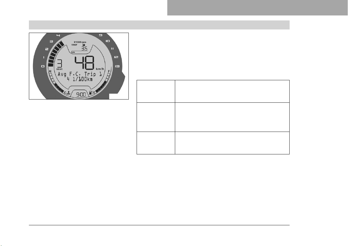
8.12.3 Avg F.C. Trip 1
COMBINATION INSTRUMENT 8
– Press the MODE button briefly and repeatedly until TRIP 1
appears on the display.
– Press the SET button briefly and repeatedly until the desired
menu appears.
Average fuel consumption 1 based on TRIP 1 is shown in this
menu.
F01382-01
Press the
SET button
briefly.
Press the
SET button
for 3 seconds.
Press the
MODE button briefly.
Next menu on the display
Display of TRIP 1 is reset
Next display mode on the display
73
Page 76
8 COMBINATION INSTRUMENT
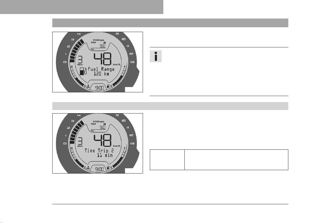
8.13 TRIP 2 display
Press the MODE button briefly and repeatedly until TRIP 2
appears on the display.
F01383-01
8.13.1 Time Trip 2
– Press the MODE button briefly and repeatedly until TRIP 2
– Press the SET button briefly and repeatedly until the desired
Riding time 2 based on TRIP 2 is shown in this menu.
Info
TRIP 2 shows the distance since the last reset, such as
between two refueling stops. TRIP 2 is always running
and counts up to 9999.9.
Press the SET button briefly to change to the next menu.
Press the MODE button briefly to change to the next display mode in the display.
appears on the display.
menu appears.
74
F01384-01
Press the
SET button
briefly.
Next menu on the display
Page 77
COMBINATION INSTRUMENT 8
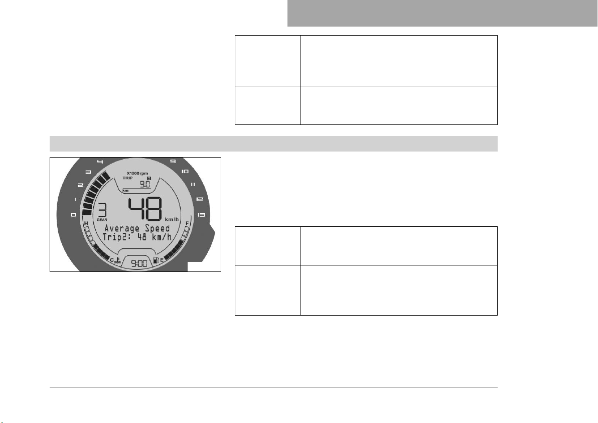
8.13.2 Average Speed Trip2
F01385-01
Press the
SET button
for 3 seconds.
Press the
MODE button briefly.
– Press the MODE button briefly and repeatedly until TRIP 2
appears on the display.
– Press the SET button briefly and repeatedly until the desired
menu appears.
Average speed 2 based on TRIP 2 is shown in this menu.
Press the
SET button
briefly.
Press the
SET button
for 3 seconds.
Display of TRIP 2 is reset
Next display mode on the display
Next menu on the display
Display of TRIP 2 is reset
75
Page 78
8 COMBINATION INSTRUMENT
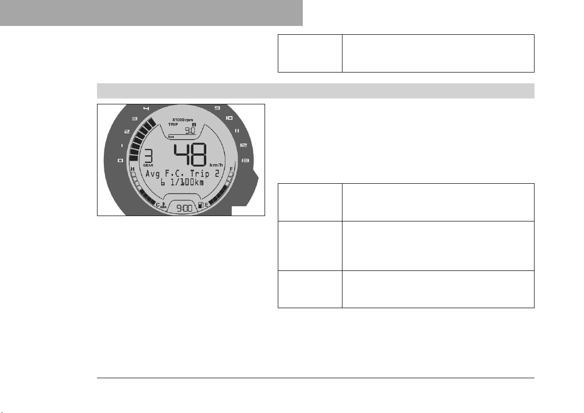
8.13.3 Avg F.C. Trip 2
F01386-01
Press the
MODE button briefly.
– Press the MODE button briefly and repeatedly until TRIP 2
appears on the display.
– Press the SET button briefly and repeatedly until the desired
menu appears.
Average fuel consumption 2 based on TRIP 2 is shown in this
menu.
Press the
SET button
briefly.
Press the
SET button
for 3 seconds.
Press the
MODE button briefly.
Next display mode on the display
Next menu on the display
Display of TRIP 2 is reset
Next display mode on the display
76
Page 79
COMBINATION INSTRUMENT 8
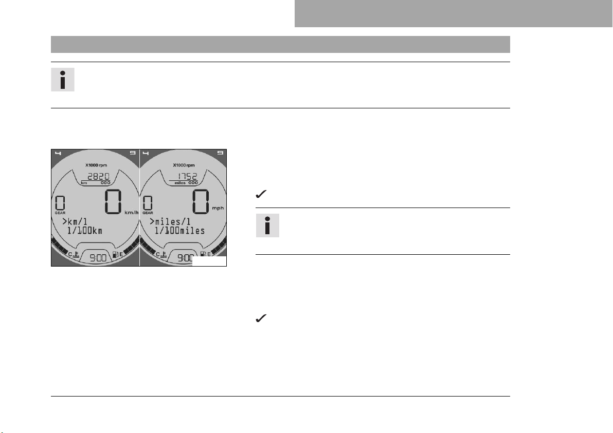
8.14 Setting the units
Info
Make the setting according to the country.
If you change the unit, the value ODO is retained and converted accordingly.
Condition
The motorcycle is stationary.
– Press the MODE button briefly and repeatedly until ODO
appears on the display.
– Press the MODE button for 5 seconds.
The units display appears.
Info
The units display is shown on the ODO display for
each menu by keeping the MODE button pressed.
F01402-01
– Press the SET button briefly and repeatedly until the desired
unit appears.
– Do not actuate MODE button and SET button for about 5
seconds.
The units display disappears and the selected unit of the
first line is adopted and saved.
77
Page 80
8 COMBINATION INSTRUMENT
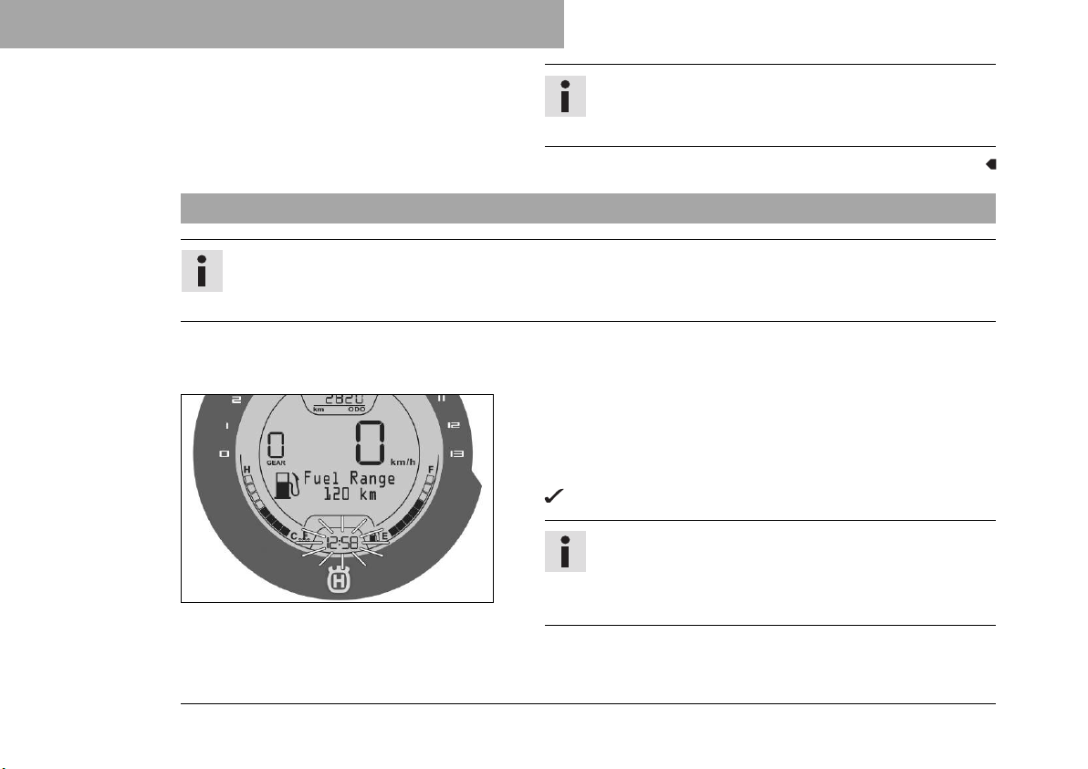
8.15 Setting the clock
Info
The clock is displayed in 24-hour format.
The time must be reset if the battery was disconnected from the vehicle or the fuse was removed.
Condition
The motorcycle is stationary.
– Press the MODE button briefly and repeatedly until ODO
– Press the MODE button and SET button simultaneously for 5
F01410-10
Info
km or miles can be set as a length unit.
l, USga, or UKga can be set as a volume unit.
appears on the display.
seconds.
The time display begins to flash.
Info
The clock can be set in the ODO display for each
menu by keeping the MODE button and SET button
pressed simultaneously.
78
Page 81
– Set the hours display using the MODE button.
– Set the minutes display using the SET button.
– Press the MODE button and SET button simultaneously.
8.16 Adjusting the shift speed RPM1
Condition
The motorcycle is stationary.
ODO > 1000 km (621 mi).
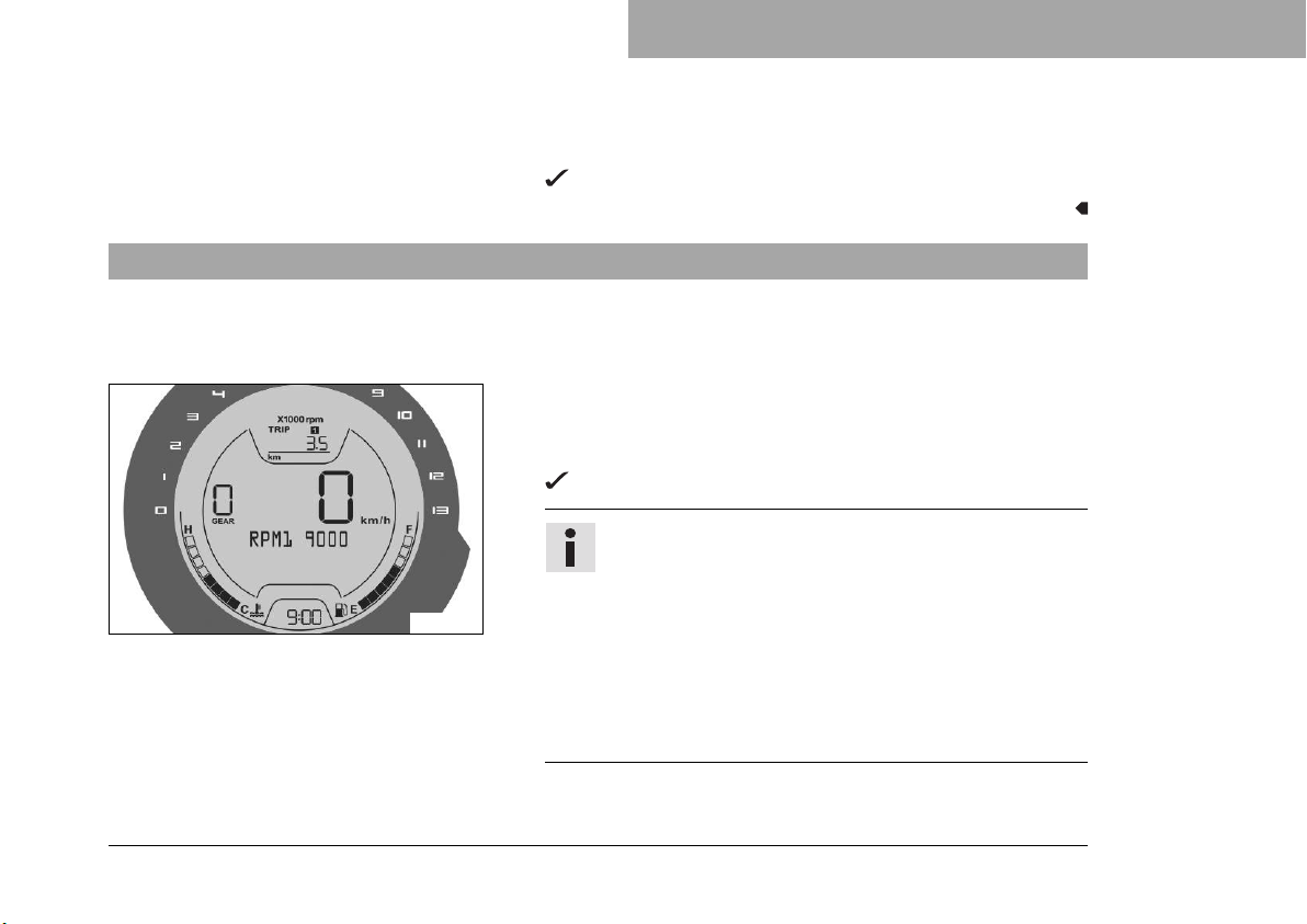
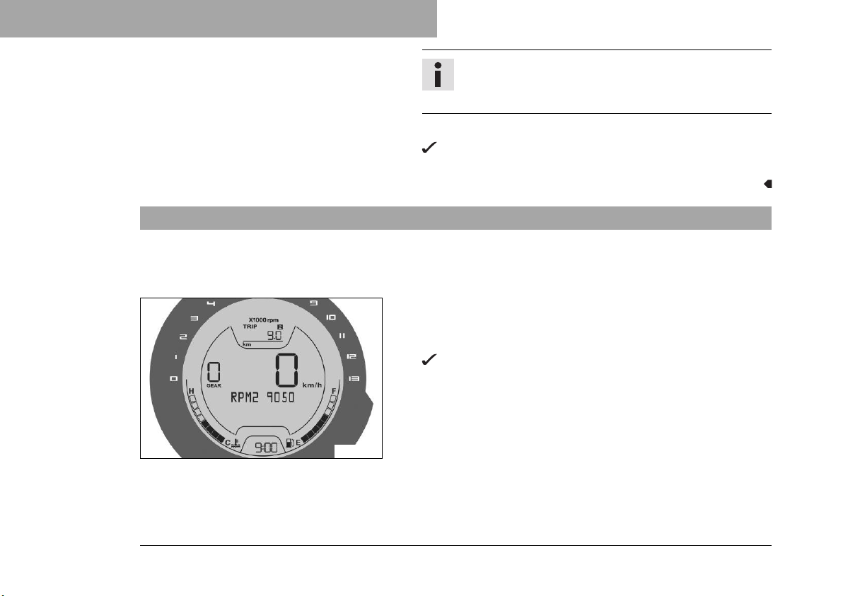
– Press the MODE button briefly and repeatedly until TRIP 1
appears on the display.
– Press the MODE button for 5 seconds.
F01400-01
COMBINATION INSTRUMENT 8
The set time is adopted and saved.
The RPM1 display appears.
Info
The RPM1 display appears in the TRIP 1 display for
each menu by keeping the MODE button pressed.
RPM1 is the engine speed above which the shift
warning light starts flashing.
The engine speed can be set at intervals of 50.
The shift speed RPM1 can only be set up to maximum 50 revolutions per minute below the shift speed
RPM2.
– Set the speed with the MODE button and SET button.
79
Page 82
8 COMBINATION INSTRUMENT
– Press the MODE button and SET button simultaneously.
8.17 Adjusting the shift speed RPM2
Condition
The motorcycle is stationary.
ODO > 1000 km (621 mi).
– Press the MODE button briefly and repeatedly until TRIP 2
– Press the MODE button for 5 seconds.
Info
The MODE button increases the value.
The SET button decreases the value.
The RPM1 display disappears and the set shift speed
RPM1 is adopted and saved.
appears on the display.
The RPM2 display appears.
80
F01401-01
Page 83
COMBINATION INSTRUMENT 8
Info
The RPM2 display appears in the TRIP 2 display for
each menu by keeping the MODE button pressed.
RPM2 is the engine speed above which the shift
warning light lights up.
The engine speed can be set at intervals of 50.
The shift speed RPM2 can only be set from a minimum of 50 revolutions per minute above the shift
speed RPM1.
– Set the speed with the MODE button and SET button.
Info
The MODE button increases the value.
The SET button decreases the value.
– Press the MODE button and SET button simultaneously.
The RPM2 display disappears and the set shift speed
RPM2 is adopted and saved.
81
Page 84
9 PREPARING FOR USE
9.1 Advice on preparing for first use
Danger
Danger of accidents A rider who is not fit to ride poses a danger to him or herself and others.
– Do not operate the vehicle if you are not fit to ride due to alcohol, drugs or medication.
– Do not operate the vehicle if you are physically or mentally impaired.
Warning
Risk of injury Missing or poor protective clothing presents an increased safety risk.
– Wear appropriate protective clothing such as helmet, boots, gloves as well as trousers and a jacket
with protectors on all rides.
– Always wear protective clothing that is in good condition and meets the legal regulations.
Warning
Danger of crashing Different tire tread patterns on the front and rear wheel impair the handling char-
acteristic.
Different tire tread patterns can make the vehicle significantly more difficult to control.
– Make sure that only tires with a similar tire tread pattern are fitted to the front and rear wheel.
Warning
Danger of accidents Non-approved or non-recommended tires and wheels impact the handling
characteristic.
– Only use tires/wheels approved by Husqvarna Motorcycles with the corresponding speed index.
82
Page 85
PREPARING FOR USE 9
Warning
Danger of accidents New tires have reduced road grip.
The contact surface on new tires is not yet roughened.
– Run in new tires with moderate riding at alternating angles.
Running-in phase 200 km (124 mi)
Info
When using the vehicle, remember that others may feel disturbed by excessive noise.
– Ensure that the pre-delivery inspection work has been carried out by an authorized Husqvarna Motorcy-
cles workshop.
The delivery certificate and the Service and Manufacturer Warranty Booklet must be transferred with
the vehicle.
– Read the entire Owner's Manual before riding for the first time.
– Get to know the controls.
– Get used to handling the motorcycle in a suitable area before undertaking a more demanding ride. Also,
ride as slowly as possible to get a better feeling for the motorcycle.
– Hold the handlebar firmly with both hands and keep your feet on the footrests when riding.
– Do not make any trips that exceed your personal ability and experience.
– Run the engine in. ( p. 84)
83
Page 86
9 PREPARING FOR USE
9.2 Running in the engine
– During the running-in phase, do not exceed the specified engine speed.
Guideline
Maximum engine speed
During the first: 1,000 km (620 mi) 7,500 rpm
Info
During the running-in phase, the shift warning light is set to a specified value and cannot be
changed.
– Avoid fully opening the throttle!
9.3 Loading the vehicle
Warning
Danger of accidents Total weight and axle loads influence the handling characteristic.
The total weight consists of: motorcycle ready for operation and with a full tank, driver and passenger
with protective clothing and helmet, and luggage.
– Do not exceed the maximum permissible overall weight or the axle loads.
84
Page 87
PREPARING FOR USE 9
Warning
Danger of accidents Improper mounting of cases or the tank rucksack impairs the handling charac-
teristic.
– Mount and secure cases and tank rucksack according to the manufacturer's instructions.
Warning
Danger of accidents The luggage system will be damaged if it is overloaded.
– Read the manufacturer information on maximum payload when mounting cases.
Warning
Danger of accidents Luggage which has slipped impairs visibility.
If the tail light is covered, you are less visible to traffic behind you, especially when it is dark.
– Check that your luggage is fixed properly at regular intervals.
Warning
Danger of accidents A high payload alters the handling characteristic and increases the stopping
distance.
– Adapt your speed to your payload.
Warning
Danger of accidents Pieces of luggage which have slipped impair the handling characteristic.
– Check that your luggage is fixed properly at regular intervals.
85
Page 88
9 PREPARING FOR USE
– If luggage is carried, ensure it is fixed firmly as close as possible to the center of the vehicle and ensure
even weight distribution between the front and rear wheels.
– Do not exceed maximum permissible weight and maximum permissible axle loads.
Guideline
Maximum permissible overall weight 355 kg (783 lb.)
Maximum permissible front axle load 135 kg (298 lb.)
Maximum permissible rear axle load 230 kg (507 lb.)
86
Page 89
RIDING INSTRUCTIONS 10
10.1 Checks and maintenance measures when preparing for use
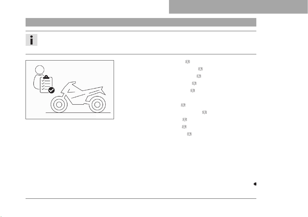
Info
Before every trip, check the condition of the vehicle and ensure that it is roadworthy.
The vehicle must be in perfect technical condition when it is being operated.
– Check the engine oil level. ( p. 211)
– Check the front brake fluid level. ( p. 148)
– Check the rear brake fluid level. ( p. 153)
– Check the front brake linings. ( p. 152)
– Check the rear brake linings. ( p. 156)
– Check that the brake system is functioning properly.
– Check the coolant level. ( p. 199)
H02217-01
– Check for chain dirt accumulation. ( p. 136)
– Check the chain tension. ( p. 138)
– Check the tire condition. ( p. 171)
– Check the tire air pressure. ( p. 174)
– Check the settings of all controls and ensure that they can be
operated smoothly.
– Check that the electrical system is functioning properly.
– Check that luggage is properly secured.
– Sit on the motorcycle and check the rear mirror setting.
– Check the fuel level.
87
Page 90
10 RIDING INSTRUCTIONS
10.2 Starting
Danger
Danger of poisoning Exhaust gases are toxic and inhaling them may result in unconsciousness and
death.
– Always make sure there is sufficient ventilation when running the engine.
– Use an effective exhaust extraction system when starting or running the engine in an enclosed
space.
Caution
Danger of accidents Electronic components and safety devices will be damaged if the battery is dis-
charged or missing.
– Never operate the vehicle with a discharged battery or without a battery.
Note
Engine damage Unfiltered intake air has a negative effect on the service life of the engine.
Dust and dirt will enter the engine without an air filter.
– Never start to use the vehicle without an air filter.
Note
Engine damage High revving speed with a cold engine negatively impacts the lifespan of the engine.
– Always run the engine warm at a low speed.
88
Page 91
B00782-10
RIDING INSTRUCTIONS 10
– Unlock the steering. ( p. 41)
– Sit on the vehicle, take the weight off of the side stand, and
move up all the way.
– Turn the emergency OFF switch to the position .
– Switch on the ignition by turning the ignition key to the posi-
tion .
After you switch on the ignition, you can hear the fuel
pump working for about two seconds. The function
check of the combination instrument is run at the same
time.
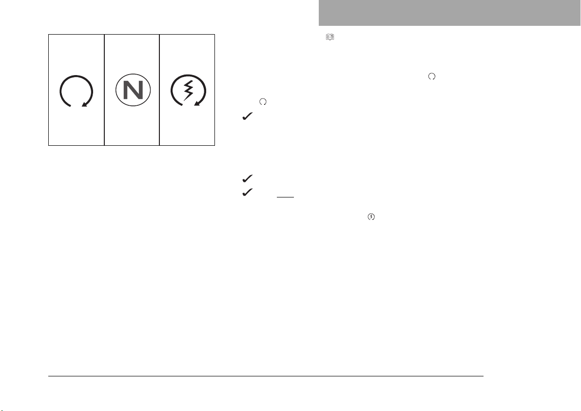
– Shift gear to neutral.
The green idle indicator lamp N lights up.
The ABS warning lamp lights up and goes back out after
starting off.
– Press the electric starter button .
89
Page 92
10 RIDING INSTRUCTIONS
10.3 Starting off
– Pull the clutch lever, engage 1st gear, release the clutch lever slowly, and simultaneously open the throttle
carefully.
Info
Do not press the electric starter button until the combination instrument function check is finished.
When starting, DO NOT open the throttle. If you open
the throttle during the starting procedure, fuel is not
injected by the engine management system and the
engine cannot start.
Press the starter for a maximum of 5 seconds. Wait for
a least 5 seconds before trying again.
This motorcycle is equipped with a safety starting
system. You can only start the engine if the transmission is in neutral or if the clutch lever is pulled when
a gear is engaged. If the side stand is folded out and
you shift into gear and release the clutch, the engine
stops.
90
Tip
If the engine dies while starting off, only pull the clutch lever and press the electric starter button.
You do not need to shift into neutral.
Page 93
RIDING INSTRUCTIONS 10
10.4 Shifting, riding
Warning
Danger of accidents Abrupt load alterations can cause the vehicle to get out of control.
– Avoid abrupt load alterations and sudden braking actions.
– Adapt your speed to the road conditions.
Warning
Danger of accidents If you change down at high engine speed, the rear wheel blocks and the engine
races.
– Do not change into a low gear at high engine speed.
Warning
Danger of accidents An incorrect ignition key position causes malfunctions.
– Do not change the ignition key position while driving.
Warning
Danger of accidents Adjustments to the vehicle distract attention from traffic activity.
– Make all adjustments when the vehicle is at a standstill.
91
Page 94
10 RIDING INSTRUCTIONS
Warning
Risk of injury The passenger may fall from the motorcycle if they conduct themselves incorrectly.
– Ensure that the passenger sits correctly on the passenger seat, places his or her feet on the pas-
senger foot pegs and holds on to the rider or the grab handles.
– Note the regulations governing the minimum age of passengers in your country.
Warning
Danger of accidents A risky riding style constitutes a major risk.
– Comply with traffic regulations and ride defensively and with foresight to detect sources of danger
as early as possible.
Warning
Danger of accidents Cold tires have reduced road grip.
– Ride the first miles carefully on every journey at moderate speed until the tires reach operating tem-
perature.
Warning
Danger of accidents New tires have reduced road grip.
The contact surface on new tires is not yet roughened.
– Run in new tires with moderate riding at alternating angles.
Running-in phase 200 km (124 mi)
92
Page 95
RIDING INSTRUCTIONS 10
Warning
Danger of accidents Pieces of luggage which have slipped impair the handling characteristic.
– Check that your luggage is fixed properly at regular intervals.
Warning
Danger of accidents A fall can damage the vehicle more seriously than it may first appear.
– Check the vehicle after a fall as you do when preparing for use.
Note
Engine failure Overheating damages the engine.
– If the coolant temperature warning is displayed, stop immediately and take care not to endanger yourself or
other traffic participants in the process.
– Allow the engine and cooling system to cool down.
– Check and, if necessary, correct the coolant level on the cooling system while it is in a cooled state.
Info
If unusual noises occur during operation, stop immediately, switch off the engine, park the vehicle properly, and contact an authorized Husqvarna Motorcycles workshop.
93
Page 96
10 RIDING INSTRUCTIONS
401950-11
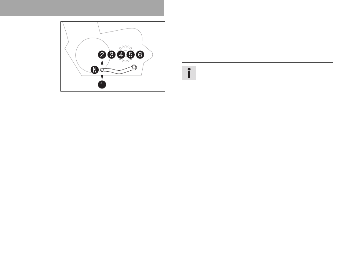
– Shift into a higher gear when conditions allow (incline, road
situation, etc.).
– Release the throttle while simultaneously pulling the clutch
lever, shift into the next gear, release the clutch lever, and
open the throttle.
Info
You can see the positions of the 6 forward gears in
the figure. The idle position is between the first and
second gears. First gear is used for starting off or for
steep inclines.
– Accelerate only up to a speed suitable for the road surface
and weather conditions. Particularly in bends, do not shift,
and accelerate very carefully.
– Brake if necessary and close the throttle at the same time in
order to shift down.
– Pull the clutch lever and shift into a lower gear, release the
clutch lever slowly, and open the throttle or shift again.
– Switch off the engine if running at idle or stationary for a long
time.
– After reaching maximum speed by fully opening the throt-
tle grip, turn the throttle back so it is ¾ open. This will barely
reduce the speed but fuel consumption will be considerably
lower.
94
Page 97
RIDING INSTRUCTIONS 10
– Accelerate only up to a speed suitable for the road surface
and weather conditions. Particularly in bends, do not shift,
and accelerate very carefully.
– Brake if necessary and close the throttle at the same time in
order to shift down.
– Pull the clutch lever and shift into a lower gear, release the
clutch lever slowly, and open the throttle or shift again.
– If the engine stalls (e.g. at a crossroads), just pull the clutch
lever and press the electric starter button. You do not have to
shift into neutral.
– If the malfunction indicator lamp lights up during a trip,
please contact an authorized Husqvarna Motorcycles workshop as soon as possible.
– If the general warning symbol begins to flash in the display
during the trip, several warnings have been detected.
Info
Warnings which have occurred are shown and saved
in the Info display until these are no longer active.
95
Page 98
10 RIDING INSTRUCTIONS
10.5 Applying the brakes
Warning
Danger of accidents Moisture and dirt impair the brake system.
– Brake carefully several times to dry out and remove dirt from the brake linings and the brake discs.
Warning
Danger of accidents A spongy pressure point on the front or rear brake reduces braking efficiency.
– Check the brake system and do not continue riding until the problem is eliminated. (Your authorized
Husqvarna Motorcycles workshop will be glad to help.)
Warning
Danger of accidents The brake system fails in the event of overheating.
If the foot brake lever is not released, the brake linings drag continuously.
– Take your foot off the foot brake lever when you are not braking.
Warning
Danger of accidents Higher total weight increases the stopping distance.
– Take the longer stopping distance into account when carrying a passenger or luggage with you.
Warning
Danger of accidents Salt on the roads impairs the brake system.
– Brake carefully several times to remove salt from the brake linings and the brake discs.
96
Page 99
RIDING INSTRUCTIONS 10
Warning
Danger of accidents ABS may increase the stopping distance in certain situations.
– Adjust application of the brakes to the respective riding situation and riding surface conditions.
Warning
Danger of accidents Excessively forceful application of the brakes blocks the wheels.
The ABS effectiveness is only ensured if it is switched on.
– Leave the ABS switched on in order to benefit from the protective effect.
– When braking, release the throttle and apply the front and rear brakes at the same time.
Info
When the ABS is enabled, maximum braking power can be achieved even with low road grip surfaces such as sandy, wet, or slippery terrain without locking the wheels.
Warning
Danger of accidents The rear wheel can lock due to the engine braking effect.
– Pull in the clutch, if you perform emergency or full braking, or if you brake on a slippery ground.
Warning
Danger of accidents Banked or laterally sloping ground reduces the maximum possible delay.
– If possible finish braking before going into a bend.
– Always finish braking before you go into a bend. Shift down to a lower gear appropriate to your speed.
97
Page 100
10 RIDING INSTRUCTIONS
– Use the braking effect of the engine on long downhill stretches. Shift back one or two gears, but do not
overrev the engine when doing so. This means that significantly less braking is required and the brake system does not overheat.
10.6 Stopping, parking
Warning
Risk of injury People who act without authorization endanger themselves and others.
– Do not leave the vehicle unattended if the engine is running.
– Protect the vehicle against access by unauthorized persons.
– Lock the steering and remove the ignition key if you leave the vehicle unattended.
Warning
Danger of burns Some vehicle components become very hot when the vehicle is operated.
– Do not touch any parts such as the exhaust system, radiator, engine, shock absorber, or brake sys-
tem before the vehicle parts have cooled down.
– Let the vehicle parts cool down before you perform any work on the vehicle.
Note
Material damage The vehicle may be damaged by incorrect procedure when parking.
Significant damage may be caused if the vehicle rolls away or falls over.
The components for parking the vehicle are designed only for the weight of the vehicle.
– Park the vehicle on a firm and level surface.
– Ensure that nobody sits on the vehicle when the vehicle is parked on a stand.
98
 Loading...