

Page 1

Oper ator ′ s manual
Rider 220T
Rider 322T
Please r ead the operator’s manual carefully and make sure you
understand the instructions bef
AWD
ore using the machine.
EEEEnnnngggglllliiiisssshh
hh
Page 2

2
T
T
CONTENTS
Contents
CONTENTS
Contents ...................................................................... 2
Ser vice journal
Pre-deliv ery service ..................................................... 3
After the first 8 hours ................................................... 3
INTR ODUCTION
Dear Customer , ............................................................ 4
Driving and transport on public roads .......................... 4
Towing .......................................................................... 4
Use .............................................................................. 4
Good service ................................................................ 4
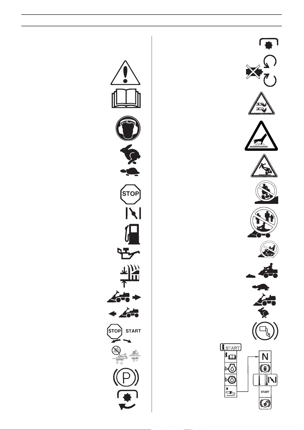
KEY TO SYMBOLS
Symbols ....................................................................... 8
WHA T IS WHAT?
What is what on the r ide-on mower ............................. 10
SAFETY INSTR UCTIONS
Saf ety instructions ........................................................ 11
Driving on slopes ......................................................... 12
Children ....................................................................... 13
Maintenance ................................................................ 13
Transport ...................................................................... 14
PRESENT ATION
Presentation ................................................................. 15
Throttle trigger ............................................................. 15
Choke control ............................................................... 15
Speed limiter ................................................................ 15
Parking brake ............................................................... 15
Cutting unit ................................................................... 15
Lifting lever for the cutting unit ..................................... 16
Cutting height adjustment lever ................................... 16
Lights ........................................................................... 16
Counter ........................................................................ 16
Seat ............................................................................. 16
Fueling ......................................................................... 16
Release lever ............................................................... 17
Driving
Bef ore starting ............................................................. 18
Start the engine ........................................................... 18
Starting the engine with a weak battery ....................... 19
Driving the Rider .......................................................... 19
Cutting tips .................................................................. 20
Stop the engine ............................................................ 20
Maintenance
Maintenance schedule ................................................. 21
Cleaning ....................................................................... 22
Removing of the machine hoods ................................. 22
Checking and adjusting the steering wires ..................
Adjusting the parking brake Rider 220T ....................... 23
Adjusting the parking brake Rider 322T AWD.............. 23
Checking and adjusting of throttle wire ........................ 23
Checking and adjusting the choke wire ....................... 24
Replacement of fuel filter ............................................. 24
Checking the fuel pump’s air filter ................................ 24
Replacing the air filter .................................................. 24
Ignition system ............................................................. 25
22
Check the safety system .............................................. 25
Replacing the light bulbs .............................................. 26
Main fuse ...................................................................... 26
Checking the tyre pressure .......................................... 26
Checking the engine’s cooling air intake ...................... 27
Fitting the cutting head ................................................. 27
Removing the cutting unit ............................................. 28
Checking and adjustment of the cutting unit’s ground
pressure ....................................................................... 28
Checking the cutting unit’s parallelism ......................... 29
Adjusting the parallelism of the cutting unit .................. 29
Replacing the cutting unit belts .................................... 29
Service position for the cutting unit .............................. 30
Checking the blades ..................................................... 31
Removing the BioClip plug ........................................... 31
Lubrication
Chec king the engine’s oil level. .................................... 32
Changing the oil filter ................................................... 32
Checking the transmission oil level .............................. 33
Lubricating the belt adjuster ......................................... 33
General lubrication ....................................................... 33
roubleshooting schedule
Storage
Winter stor age .............................................................. 35
Guard ........................................................................... 35
Service ......................................................................... 35
echnical data
36
–
English
Page 3

1
1
Ser
vice journal
Pre-deliver y service
Charge the battery for 4 hours at max. 3 amp.
2 Fit steering wheel, seat and any optional
equipment.
3 Chec k and adjust tyre pressure (60 Kpa, 0.6 bar,
9 PSI).
4 Adjust cutting unit:
Adjust lift springs (effective weight of cutting unit
should be 12-15kg / 26.5-33 lb).
Adjust cutting unit so that rear edge is about 2-4
mm / 1/8”
Adjust the cutting unit’s cutting height setting so
that the connection rod is tensed at the lo
cutting height.
5 Chec k that the right amount of oil is in the engine.
6 Check that there is oil in the transmission’s oil
tank.
7 Connect battery.
8 Fill with fuel and start engine.
9 Check that machine does not move in neutral.
higher than front edge.
west
13 Tell customer about:
Needs and benefits of following the service
schedule
Servicing and the influence of this journal on the
second-hand v
Range of applications for BioClip.
Complete proof of sale etc.
Pre-delivery service carried out. No outstanding problems.
tified:
Cer
________________________________________________
Date, mileage, stamp, signature
.
alue of the machine.
10 Check:
Forward drive.
Reverse drive.
Oper ation of blades.
Seat saf ety switch.
Lif le ver safety switch.
The saf ety switch for the hydrostat pedals.
11 Check the engine speed See the Technical data
section.
12 Check the synchronisation between the front and
rear wheels
workshop manual.
. (Only AWD-machines) See the
After the fi rst 8 hours
Change engine oil
2 Change the oil in the gearbox. (Only AWD-
machines)
3 Chec k the synchronisation between the front and
rear wheels
. (Only AWD-machines)
English
– 3
Page 4

4
T
INTR ODUCTION
Dear Customer ,
Thank y ou for choosing a Husqvarna Rider . Husqvarna Riders are built to a unique design with a front-mounted cutting unit and a
patented ar
controls and pedal-operated hydrostatic transmission also contribute to the performance of this machine.
This operator’s manual is a valuable document. By following its instructions (on operation, service, maintenance, etc.) you will
significantly e
When you sell your Rider, make sure you pass on the operator’s manual to the new owner.
The last chapter in the operator’s manual consists of a Service Journal. Mak e sure that all service work and repairs are recorded.
A well-documented service history reduces the costs of seasonal maintenance and influences the second-hand value of the
machine. Bring the operator’s manual with the Rider when bringing it to a workshop for service procedures.
Driving and transpor t on public roads
Chec k the relevant road traffic regulations before driving the machine on a public road. If transporting the machine on another
v
ehicle always use approved securing devices and make sure that the machine is securely held.
owing
When y our machine is equipped with a hydrostatic transmission you should only tow the machine over short distances and at a
lo
w speed, otherwise there is a risk of damaging the transmission.
The power transmission must be disengaged when towing, see the instructions under the heading Clutch control.
ticulated steering. Riders are designed for maximum efficiency even in small or confined areas. The closely grouped
xtend the life of the machine and even its second-hand value.
Use
This r ide-on mower is designed to mow grass on open and level ground surfaces. In addition, there is a number of accessories
recommended b
which accessories are available. The machine may only be used with the equipment recommended by the manuf acturer. All other
types of use are incorrect. Compliance with and strict adherence to the conditions of operation, service and repair as specified by
the manufacturer also constitute essential elements of the intended use.
IMPOR TANT INFORMATION The transmission guarantee is only valid if the synchronisation of the front and rear wheels has
been chec
carried out.
This machine should be operated, serviced and repaired only by persons who are familiar with its particular characteristics and
who are acquainted with the rele
Accident prevention regulations, all other gener ally recognised regulations on safety and occupational medicine, and all road tr
regulations must be observed at all times.
Any arbitrary modifications carried out to this machine may relieve the manufacturer of liability for any resulting damage or injur
y the manufacturer that broadens the application area. Please contact your dealer for more information about
ked and adjusted in compliance with the service schedule. The system will be damaged if synchronisation is not
vant safety procedures.
affic
Good ser vice
Husqv arna products are sold all over the world and ensures that you, the customer , get the best support and service. For e xample,
before this machine was delivered it was inspected and adjusted by your dealer. See the certificate in the Service Journal in this
manual.
When you need spare parts or advice on service issues, warranty terms, etc., contact:
y.
This Operator’s Manual belongs to machine with
ser
ial number:
On the machine's rating plate you will find the following information:
• The machines type designation.
• The manufacturer’s type number.
• The machine’s serial number.
State the type designation and serial number when ordering spare parts.
–
English
Engine Transmission
Page 5

mo
f
f
I.
SAFETY R
•
Saf e operation practices f or ride-on
ULES FOR USA
wer s
These instr uctions are f or y our saf ety . Read them
carefully .
IMPOR T ANT!
This cutting mac hine is capab le of amputating hands and
eet and thr o wing objects. F ailure to obser ve the
ollo wing saf ety instructions could result in serious
injur y or death.
General operation
1. Read, understand and f ollo w all instr uctions in the man ual
and on the machine bef ore star ting.
2. Only allo w responsib le adults , who are f amiliar with the
instr uctions , to oper ate the machine .
3. Clear the area of objects such as roc ks , to ys , wire , etc.,
which could be pic k ed up and thro wn b y the b lade .
4. Be sure the area is clear of other people bef ore mo wing.
Stop the machine if an y one enters the area.
5. Ne v er carr y passengers .
6. Do not mo w in re
Always look down and behind before and while backing.
7.Be aware of the mower discharge direction and do not point
it at anyone. Do not operate the mower without either the
entire grass catcher or the guard in place.
8.Slow down before turning.
9.Never lea ve a running machine unattended. Always turn off
blades, set parking brake, stop engine and remove keys
before dismounting.
10.Turn off blades when not mowing.
11.Stop engine before removing grass catcher or unclogging
chute.
12.Mow only in daylight or good artificial light.
13.Do not operate the machine while under the influence of
alcohol or drugs.
14.Watch for traffic when operating near or crossing
roadways.
15.Use extra care when loading or unloading the machine
into a trailer or truck.
verse unless absolutely necessary.
Watch for holes , ruts or bumps. Uneven terrain could overturn
the machine. Tall grass can hide obstacles.
Use slow speed. Choose a low gear so that you will not have
to stop or shift while on the slope.
Follow the manufacturer’s recommendations for wheel
weights or counterweights to improve stability.
Use extra care with grass catchers or other attachments.
These can change the stability of the machine.
Keep all movement on the slopes slow and gradual. Do not
make sudden changes in speed or direction.
Avoid starting or stopping on a slope. If tires lose traction,
disengage the blades and proceed slowly straight down the
slope.
DO NOT
Do not turn on slopes unless necessary and then, turn slowly
and gradually downhill, if possible.
Do not mow near drop-offs, ditches or embandments. The
mower could suddenly turn over if a wheel is over the edge of
a cliff or ditch, or if an edge caves in.
Do not mow on wet grass. Reduced traction could cause
sliding.
Do not try to stabilize the machine by putting your foot on the
ground.
Do not use grass catcher on steep slopes.
III.Children
Tragic accidents can occur if the operator is not alert to the
presence of children. Children are often attracted to the
machine and the mowing activity . Never assume that children
will remain where you last saw them.
1.Keep children out of the mowing area and under the
watchful care of another responsible adult.
2.Be alert and turn machine off if children enter the area.
3.Before and when backing, look behind and down for small
children.
4.Never carry children. They may fall off and be seriously
injured or interfere with safe machine operation.
5.Never allow children to operate the machine.
6.Use extra care when approaching blind corners, shrubs,
trees or other objects that may obscure vision.
II.Slope operation
Slopes are a major factor related to loss-of-control and tipover accidents, which can result in severe injury or death. All
slopes require extra caution. If you cannot back up the slope
or if you feel uneasy on it, do not mow it.
DO
Mow up and down slopes, not across.
Remove obstacles such as rocks, tree limbs, etc.
English
– 5
Page 6

SAFETY RULES FOR USA
IV. Service
1. Use extra care in handling gasoline and other fuels. They
are flammable and vapours are explosive.
a) Use only an approved container.
b) Never remove gas cap or add fuel with the engine running.
Allow engine to cool before refuelling. Do not smoke.
c) Never refuel the machine indoors.
d) Never store the machine or fuel container inside where
there is an open flame, such as in a water heater.
2. Never run a machine inside a closed area.
3. Keep nuts and bolts, especially blade attachment bolts,
tight and keep equipment in good condition.
4. Never tamper with safety devices. Check their proper
operation regularly.
5. Keep machine free of grass, leaves or other debris buildup. Clean up oil or fuel spillage. Allow machine to cool before
storing.
6. Stop and inspect the equipment if you strike an object.
Repair, if necessary, before restarting.
7. Never make adjustments or repairs with the engine
running.
8. Grass catcher components are subject to wear, damage
and deterioration, which could expose moving parts or allow
objects to be thrown. Frequently check components and
replace with manufacturer’s recommended parts, when
necessary.
9. Mower blades are sharp and can cut. Wrap the blade(s) or
wear gloves and use extra caution when servicing them.
10. Check brake operation frequently. Adjust and service as
required.
Safe handling of gasoline
To avoid personal injury or property damage, use extrem care
in handling gasoline. Gasoline is extremely flammable the
vapors are explosive
1.Extinguish all cigarettes, cigars, pipes, and other sources of
ignition.
2.Use only an approved gasoline container.
3.Never remove gas cap or add fuel with the engine running.
Allow engine to cool before refueling.
4.Never fuel the machine indoors.
5.Never store the machine or fuel container where there is an
open flame, spark or pilot light such as on a water heater or
other appliances.
6.Never fill containers inside a vehicle or on a truck or trailer
bed with a plastic liner. Allways place containers on the
groundaway from your vehicle before filling
7.Remove gas-powered equipment from the truck or trailer
and refuel it on the ground. If this is not possible, then refuel
such equipment with a portable container, rather than from a
gasoline dispenser nozzle.
8.Keep the nozzle in contact with the rim of the fuel tank or
container opening at all times until the fueling is complete. Do
not use a nozzle lock-open device.
9.If fuel is spilled on clothing, change clothing immediately.
10.Never overfill fuel tank. Replace gas cap and tighten
securely.
Danger, keep hands and feet away
6 – English
Page 7

SAFETY RULES FOR USA
Travel and transport on public roads
Check the relevant road traffic regulations before driving the
machine on a public road. If transporting the machine on
another vehicle always use approved securing devices and
make sure that the machine is securely held.
Towing
If your machine has a hydrostatic transmission you should
only tow it very short distances at low speed if absolutely
necessary, otherwise the transmission may be damaged.
Intended use
This machine is designed solely for cutting grass on
conventional lawns and other cleared and leveled ground
without obstacles, as rocks, stumps etc., and, in conjunction
with accessories supplied by the manufacturer e ven f or other
special tasks for which instructions are delivered with the
accessory. Use in any other way is considered as contrary to
the intended use. Compliance with and strict adherence to the
conditions of operation, service and repair as specified by the
manufacturer also constitute essential elements of the
intended use.
This machine should be operated, serviced and repaired only
by persons who are familiar with its particular characteristics
and who are acquainted with the relevant safety procedures.
Accident prevention regulations, all other generally
recognised regulations on safety and occupational medicine,
and all road traffic regulations must be observed at all times.
Any arbitrary modifications carried out to this machine may
relieve the manufacturer of liability for any resulting damage
or injury.
Safe operation practices for Ride-On
Mowers
Before starting cutting operations, train different driving
operations on an open ground without people nearby until you
feel familiar with handling the equipment. This is particularly
important if you have no or little prior experience of driving a
vehicle.
Data indicates that operators, age 60 years and above, are
involved in a large percentage of riding mower-related
injuries. These operators should evaluate their ability to
operate the riding mower safely in order to protect themselv es
and others from serious injury.
Never carry children, even with the blades off. They may fall
off and be seriously injured or interfere with safe machine
operation.
English – 7
Page 8
KEY TO SYMBOLS
Symbols
These symbols are on the machine and in the instructions.
WARNING! Careless or incorrect use can
result in ser
operator or others.
ious or fatal injury to the
Clutch out
Warning: rotating parts. Keep hands and
feet clear.
Please read the operator’s manual
carefully and make sure you understand
the instructions before using the machine.
Always wear:
• Approved hearing protection
Fast
Slow
Stop the engine.
Choke.
Fuel
Rotary blades Keep hands and feet
way from under the hood when the
a
engine is running
Hot surface.
Risk that the machine will tip over
Never drive across a slope
Never use the machine if persons,
especially children, or animals, are in the
vicinity
Oil level
Cutting height
Backwards
Forwards
Ignition
Hydrostatic freewheel
Parking brake
Never carry passengers on the machine or
equipment
Drive very slowly if no cutting unit is fitted
The cutting deck must be fitted at full
speed.
Brake
Starting instructions
Clutch in
8 – English
Page 9
KEY TO SYMBOLS
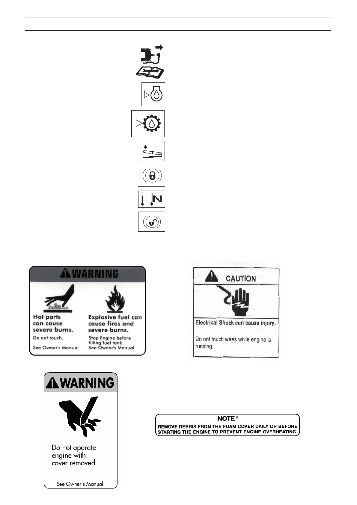
Switch off the engine and take off the ignition
cable before repairs or maintenance
Check the engine’s oil level
Check transmission oil level
Lift up the cutting unit
Apply the parking brake.
If the engine is cold, use the choke
Release the parking brake before driving
The following labels are on the machine
English – 9
Page 10

WHAT IS WHAT?
12 3 4 5
10
13 15
7
6
8
9
14 1611 12
What is what on the ride-on mower
1 Speed limiter for driving forward
2 Speed limiter for reversing
3 Lifting lever for the cutting unit
4 Cutting height adjustment lever
5 Ignition lock
6 Throttle trigger
7 Choke control
8 Counter: 322T AWD
9 Cover lock
10 Parking brake
11 Lock button for parking brake
12 Seat adjustment.
13 Lever to disengage the driving front axle: 322T AWD
14 Fuel cap
15 Battery
16 Lever to disengage the drive Rider 220T
Lever to disengage the driving rear axle, 322T AWD
English – 10
Page 11

SAFETY INSTRUCTIONS
Safety instructions
These instructions are for your safety. Read them carefully.
Insure your Rider
• Check the insurance coverage for your new Rider.
• Contact your insurance company.
• Y ou should hav e fully comprehensive insurance including:
third par
General use
• Read all the instructions in this operator’s manual and on
the machine before you start it. Ensure you understand
them and then observe them.
• Learn how to use the machine and its controls safely and
lear
safety decals.
• Only allow the machine to be used by adults who are
amiliar with its use.
f
• Make sure nobody else is in the vicinity of the machine
when y
• Clear the area of objects such as stones, toys, wires, etc.
that ma
ty, fire, damage, theft and liability
WARNING! This machine produces an
electromagnetic field during operation. This
!
field may under some circumstances
interfere with active or passive medical
implants. To reduce the risk of serious or
fatal injury, we recommend persons with
medical implants to consult their physician
and the medical implant manufacturer
before operating this machine.
n to how to stop quickly. Also learn to recognize the
ou start the engine, engage the drive or drive off.
y become caught in the blades and be thrown out.
• Stop the engine and prevent the engine from being
star
ted until you have cleaned the outlet channel.
• Look out for the ejector and do not direct it towards
yone.
an
• Stop the engine and prevent it from starting before you
clean the cutting unit.
• Remember that the driver is responsible for dangers or
accidents
• Never carry passengers. The machine is only intended to
be used b
• Always look downwards and backw ards bef ore and while
versing. Keep watch for both large and small obstacles.
re
• Slow before cornering.
• Switch off the blades when you are not mowing.
• T ake care when rounding a fixed object, so that the b lades
do not hit it.
!
!
!
• Only use the machine in daylight or in other well-lit
conditions
holes or other irregularities in the ground. P a y attention to
other possible risks.
• Never use the machine if you are tired, if you have
consumed alcohol, or if y
medication that can affect your vision, judgement or coordination.
• Keep an eye on the traffic when working close to a road or
when crossing it.
• Never leave the machine unsupervised with the engine
running. Alwa ys stop the b lades, apply the parking brak e,
stop the engine and remove the keys before leaving the
machine.
.
y one person.
Never run the machine over foreign objects.
WARNING! This machine can sever hands
and feet as well as throw objects. Failure to
observe the safety instructions can result in
serious injuries.
WARNING! The inside of the muffler contain
chemicals that may be carcinogenic. Avoid
contact with these elements in the event of a
damaged muffler.
WARNING! The engine emits carbon
monoxide, which is a colourless, poisonous
gas. Do not use the machine in enclosed
spaces.
. Keep the machine at a safe distance from
ou are taking other drugs or
English – 11
Page 12

SAFETY INSTRUCTIONS
• Never allow children or other persons not trained in the
use of the machine to use or service it. Local laws may
regulate the age of the user.
WARNING! You must use approved personal
protective equipment whenever you use the
!
machine. Personal protective equipment
cannot eliminate the risk of injury but it will
reduce the degree of injury if an accident
does happen. Ask your dealer for help in
choosing the right equipment.
• Use hearing protection to minimise the risk of hearing
ment.
impair
• Never wear loose fitting clothes that can catch in moving
parts.
• Never use the machine when barefoot. Always wear
protectiv
toes.
e shoes or protective boots, prefer ab ly with steel
This is what you do
• Remove obstacles such as stones, branches, etc.
• Mow upwards and downwards, not sideways.
• Do not use the machine on ground that slopes more than
10°.
• Take extra care if any attachments are fitted that can
change the stability of the machine
• Avoid starting or stopping on a slope. If the tyres start to
, stop the blades and drive slowly down the slope.
slip
• Always drive smoothly and slowly on slopes.
• Do not make any sudden changes in speed or direction.
• Avoid unnecessary turns on slopes, if necessary, turn
wly and gradually downwards if possible. Drive slowly.
slo
Do not turn the wheel sharply.
• Watch out for and avoid driving over furrows, holes and
umps. It is easier f or the machine to o v erturn on uneven
b
ground. Tall grass can hide obstacles.
.
• Make sure that you have first aid equipment close at hand
when using the machine
.
Driving on slopes
Driving on slopes is one of the operations where the risk of
the driver losing control of the machine or of it overturning is
the greatest; this can result in serious injury or death. All
slopes demand extra care. If you cannot re verse up a slope or
if you feel unsure, do not mow it.
IMPORTANT INFORMATION
Do not drive down slopes with the unit raised.
12 – English
• Do not mow too close to edges, ditches or banks. The
machine can suddenly o
the edge of a steep slope or a ditch, or if an edge gives
way.
• Do not mow wet grass. It is slippery, and tyres can lose
rip so that the machine skids.
their g
• Do not try to stabilize the machine by putting your foot on
round.
the g
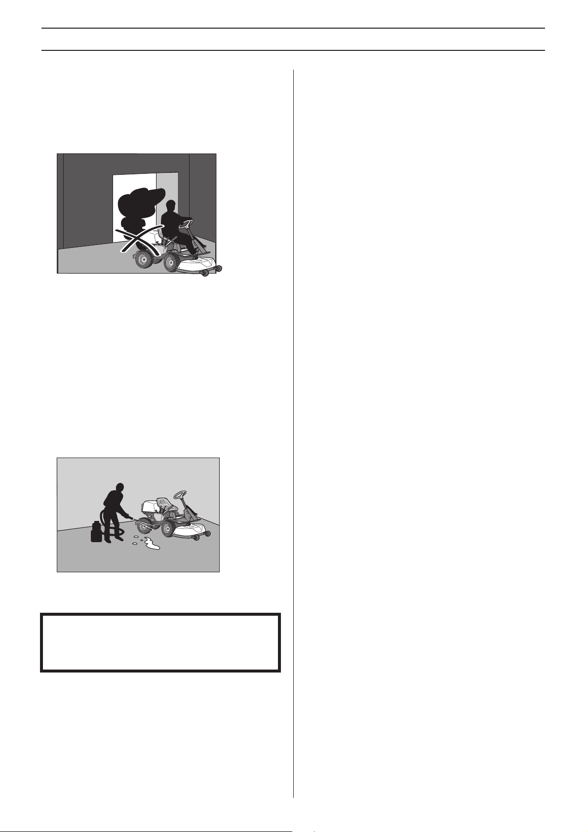
• When cleaning the chassis, the machine may never be
iven near verges or ditches.
dr
• When mowing, keep away from b ushes and other objects.
verturn if one wheel comes over
Page 13
SAFETY INSTRUCTIONS
• Follow the manufacturer’s recommendations regarding
wheel weights or counterbalance weights to increase
machine stability.
IMPORTANT INFORMATION
Wheel weights fitted on the rear wheels are recommended
when driving on slopes for safer steering and improved
manoeuvrability . Consult your dealer concerning the use of
wheel weights if you are unsure. Wheel w eights can not be
used on AWD-machines. Use counterweights.
Children
• Serious accidents may occur if you fail to be on your guard
for children in the vicinity of the machine. Children are
often attracted to the machine and mowing. Never
assume that children will remain where you last saw them.
• Keep children away from the area to be mo wed and under
close super
• Keep an eye out and shut off the machine if children enter
the w
• Before and during reversing procedures, look behind you
and do
• Never allow children to ride along. They can fall off and
iously injure themselves or be in the way for safe
ser
manoeuvring of the machine.
• Never allow children to operate the machine.
• Be particularly careful near corners, bushes, trees or
other objects that b
vision by another adult.
ork area.
wn for small children.
lock your view.
Maintenance
• Petrol and petrol fumes are poisonous and extremely
flammab
carelessness can result in personal injury or fire.
• Only store fuel in containers approved for the purpose.
• Never remove the fuel cap and fill the fuel tank when the
engine is r
• Allow the engine to cool before refuelling. Do not smoke.
Do not fill with fuel in the vicinity of spar
flames.
• Handle oil, oil filters, fuel and the battery carefully, of
en
requirements.
• Electrical shocks can cause injuries. Do not touch cables
when the engine is r
system with your fingers.
!
• If leaks arise in the fuel system, the engine must not be
star
• Store the machine and fuel in such a way that there is no
isk that leaking fuel or fumes can cause any damage.
r
• Check the fuel level before each use and leave space for
the fuel to e
the sun may otherwise cause the fuel to expand and
overflow.
• Avoid overfilling. If y ou spill petrol on the machine, wipe up
the spill and w
engine. If you spill on your clothing, change your clothing.
• Allow the machine to cool before performing any actions
in the engine compar
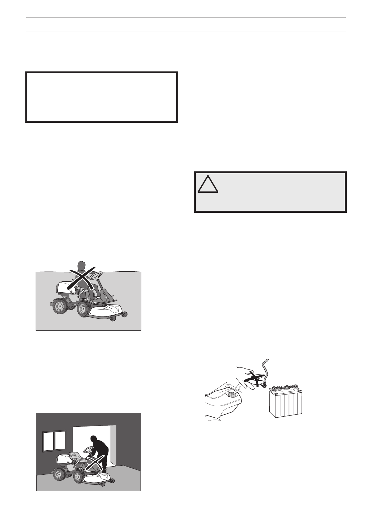
• Take care with battery maintenance. Explosive gases
orm in the battery. Never perform maintenance on the
f
battery while smoking or in the vicinity of open flames or
sparks. This can cause the battery to explode and cause
serious injuries.
le. Be especially careful when handling petrol, as
unning.
ks or naked
vironmental considerations. Follow the local recycling
unning. Do not test the ignition
WARNING! The engine and the exhaust
system become very hot during operation.
Risk of burn injuries if touched. When
mowing, keep away from bushes and other
materials in order to avoid a heating effect.
ted until the problem has been resolved.
xpand, because the heat from the engine and
ait until it has evaporated bef ore starting the
tment.
• Stop the engine. Prev ent starting by removing the ignition
cable from the spark plug or remove the ignition key
before making any adjustments or carrying out
maintenance.
• Never fill the fuel tank indoors.
• Make sure all nuts and bolts are tightened correctly and
that the equipment is in good condition.
• Do not modify safety equipment. Check regularly to be
sure it w
protective plates, protective covers, safety switches or
other protective devices are not fitted or are defective.
• Observe the risk of injury caused by moving or hot parts if
the engine is star
protective cowlings removed.
orks properly. The machine must not be driven if
ted with the engine cover open or
English – 13
Page 14
SAFETY INSTRUCTIONS
• Do not change the setting of governors. If y ou run too fast,
you risk damaging the machine components. See chapter
on Technical data for highest permitted engine speed.
• Never use the machine indoors or in spaces lacking
proper v
monoxide, an odourless, poisonous and highly dangerous
gas.
• Stop and inspect the equipment if you run over or into
an
• Never make adjustments with the engine running.
• The machine is tested and approved only with the
equipment or
manufacturer.
• The blades are sharp and can cause cuts. Wrap the
b
• Check regularly that the parking brake works. Adjust and
maintain as required.
• Reduce the risk of fire by removing grass, leaves and
other debr
Allow the machine to cool before putting it in storage.
entilation. Exhaust fumes contain carbon
ything. If necessary, make repairs before starting.
iginally provided or recommended by the
lades or wear protective gloves when handling them.
is that may have fastened on the machine.
Engage the parking brake and tie the tension belts around
le parts on the machine, e.g. frame or rear wagon.
stab
Secure the machine by tensioning the belts towards the
back and the front of the trailer respectively.
Place the wheel blocks in front of and behind the rear
.
wheels
• Check and observe local road traffic regulations before
ansporting or driving the machine on roads.
tr
Transport
IMPORTANT INFORMATION
The parking brake is not sufficient to lock the machine
during transport. Ensure you secure the machine firmly to
the transporting vehicle.
• The machine is heavy and can cause serious crush
injuries. Take extra care when loading it onto or off a
vehicle or trailer.
• Use an approved trailer to transport the machine.
• To secure the machine on the trailer, two approved
tension belts and f
be used.
14 – English
our wedge shaped wheel blocks should
Page 15
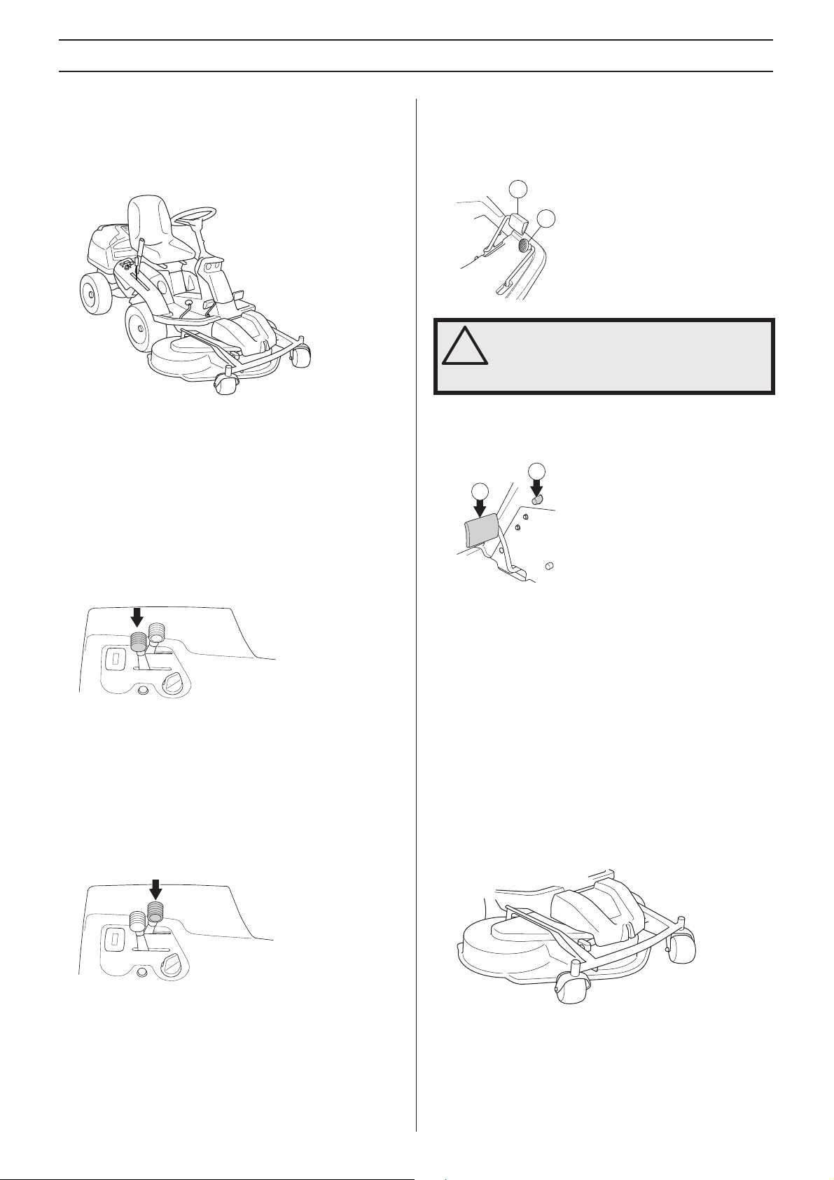
PRESENTATION
Presentation
Congratulations on your choice of an excellent quality product
that will give you great pleasure for many years. This
operator’s manual describes Rider 220T and
Rider 322T AWD.
The machine 322T AWD are equipped with all wheel drive,
chronometer and lights
The power transmission from the engine is handled by a
ydrostatic transmission, which allows variable variation of
h
the speed by using the pedals.
One pedal for driving forward and one for reverse.
.
Speed limiter
The speed of the machine is steplessly regulated with two
pedals. Pedal (1) is used to drive forwards, and pedal (2) to
drive backwards.
1
2
WARNING! Make sure that branches do not
obstruct the pedals when mowing under
!
bushes. Otherwise there is a risk you may
lose control.
Parking brake
The parking brake is applied as follows:
2
1
Throttle trigger
The throttle control regulates the engine speed, and thereby
also the rotation speed of the blades.
To increase or reduce the engine speed the control is moved
kwards or forwards.
bac
Avoid idling the engine for long periods, as there is a risk of
carbon b
uild-up on the spark plugs.
Choke control
The choke lever is used for cold starting and to give the
engine a richer fuel mixture.
1 Press down the parking brake pedal (1).
2 Press in the lock button (2) on the steering column.
3 Release the parking brak e pedal while keeping the button
pressed in.
The parking brake lock disengages automatically when the
ake pedal is pressed.
br
Cutting unit
Rider 220T and Rider 322T AWD can be equipped with three
different cutting units
• Combi 103
• Combi 112
• SD 48
For cold starting the lever is moved backwards to its end
position.
The Combi-unit, equipped with a BioClip-plug, finely chops
the cuttings to f
works in the same way as a rear ejection unit.
ertiliser. Without the BioClip-plug the unit
English – 15
Page 16
PRESENTATION
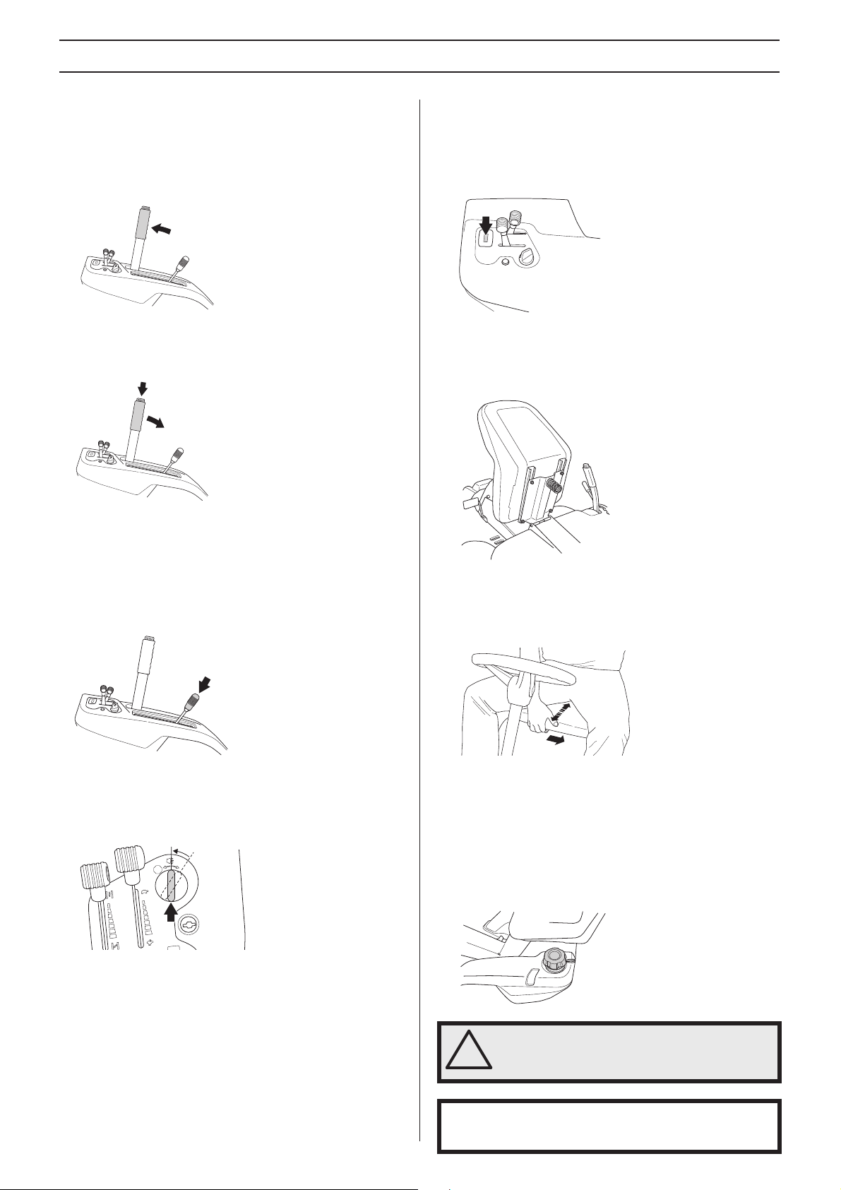
Lifting lever for the cutting unit
The lift lever is used to set the cutting unit in transport or
mowing position.
If the lever is pulled backwards the unit is raised and the
lades automatically stop rotating (transport position).
b
If the lock button is pressed in and the lev er is moved f orwards
the unit will be lo
to rotate (mowing position).
wered and the blades will automatically start
Counter: 322T AWD
The chronometer shows how many hours the engine has
been running. Any time when the engine is not running but the
ignition is switched on is not registered. The last digit shows
tenths of an hour (6 minutes).
Seat
The seat has a jointed attachment on the front edge and can
be tipped forward.
The lever can also be used to temporarily regulate the cutting
height, e
.g. for a small mound in the lawn.
Cutting height adjustment lever
The cutting height can be adjusted to 10 different positions
with the cutting height lever. 25-75 mm
Lights: 322T AWD
The lights are switched on and off using the power switch on
the control panel.
START
STOP
The seat can also be adjusted lengthways.
To adjust move the lever under the front edge of the seat to
the left, so that the seat can be mo
to the required position.
ved forward or backwards
Fueling
The engine runs on unleaded petrol with a minimum octane
rating of 87 (not mixed with oil). We recommend the use of
biodegradable alkylate petrol. (max. methanol 5%, max.
ethanol 10%, max. MTBE 15%)
Do not fill the tank completely, leave an expansion area of at
least 2.5 cm (1“).
16 – English
WARNING! Petrol is highly inflammable.
Exercise care and refuel outdoors (see
!
safety instructions).
IMPORTANT!
Do not use the fuel tank as a support area.
Page 17
PRESENTATION
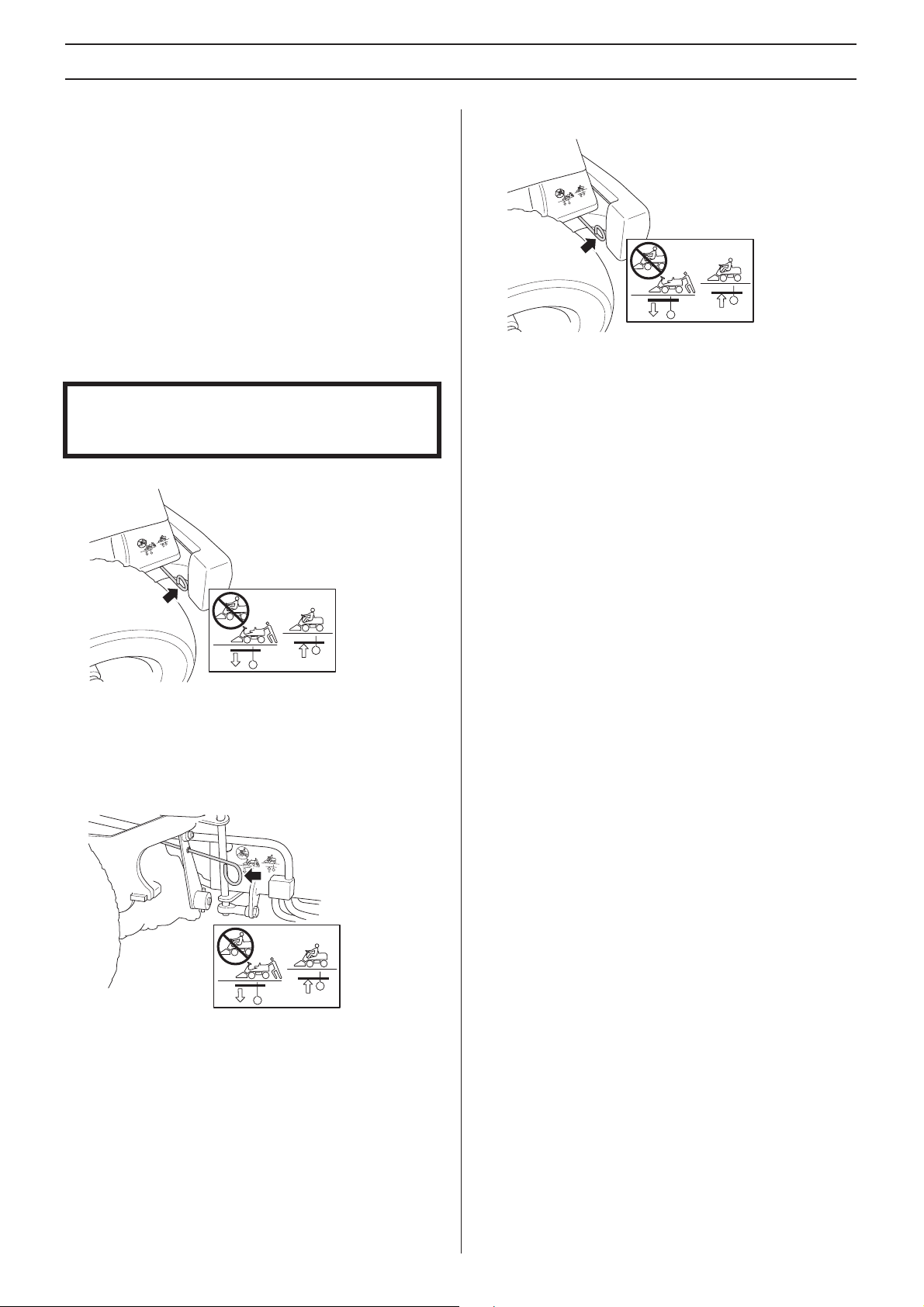
Release lever
The release control must be pulled out in order for the
machine to be moved when the engine is shutoff.
Should you attempt to drive the machine with the clutch
controls pulled out it will not mo
disengaged when one of the controls is pulled out.
Pull the controls to the end positions, do not use an
mediate position.
inter
Clutch control Rider 322T AWD
Rider 322T AWD have one control for the front axle and one
control for the rear axle.
IMPORTANT!
Always drive the machine with both clutch controls pressed
in.
• Clutch control, rear axle
ve. The drive on the axle is
Release lever Rider 220T
• Pull out the control to disengage the drive system.
Push in the control to engage to the drive system.
- Control drawn out, drive system disengaged.
- Control depressed, drive system engaged.
• Clutch control, front axle
The control is positioned on the inside of the left front
wheel.
- Rear control (pulled out), drive system disengaged.
- Front control (pushed in), drive system engaged.
English – 17
Page 18
Driving
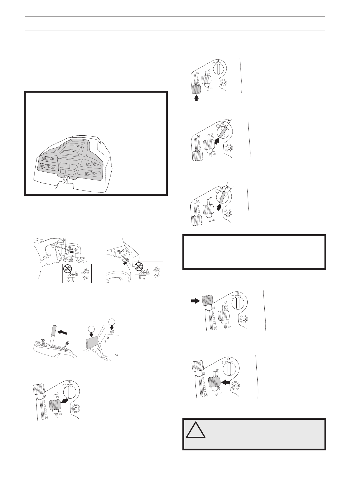
Before starting
• Read the safety instructions and information concerning
the placement of controls and functions before starting.
• Perform daily maintenance before starting as set out in
the Maintenance schedule
.
IMPORTANT INFORMATION
The air intake grille in the engine cover behind the driver’s
seat must not be blocked by, for example, clothing, leaves,
grass or dirt. Impaired cooling of the engine.
Risk of major engine damage.
Start the engine
4 If the engine is cold mo ve the choke le ver backw ards to its
end position.
START
STOP
5 Turn the ignition key to the start position.
START
STOP
6 When the engine starts release the ignition key
immediately bac
k to neutral position.
START
STOP
1 Make sure that the clutch control is depressed. Rider
322T AWD have one control for the front axle and one
control for the rear axle.
2 Lift up the cutting unit by pulling the lever backwards to
ked position (transport position) and apply the parking
loc
brake. The engine can not be started if the parking brake
is not pressed down.
2
1
3 Move the throttle control to the middle position.
START
STOP
IMPORTANT INFORMATION
Do not run the starter for more than about 5 seconds at a
time. If the engine does not start, wait about 15 seconds
before trying again.
7 Push the choke lever gradually forward when the engine
has star
ted.
START
STOP
8 Let the engine run at moderate speed or half throttle f or 3-
utes before subjecting it to heavy load.
5 min
START
STOP
18 – English
9 Set the required engine speed with the throttle control.
WARNING! Never run the engine indoors, in
enclosed or poorly ventilated areas. The
!
exhaust fumes contain toxic carbon
monoxide.
Page 19
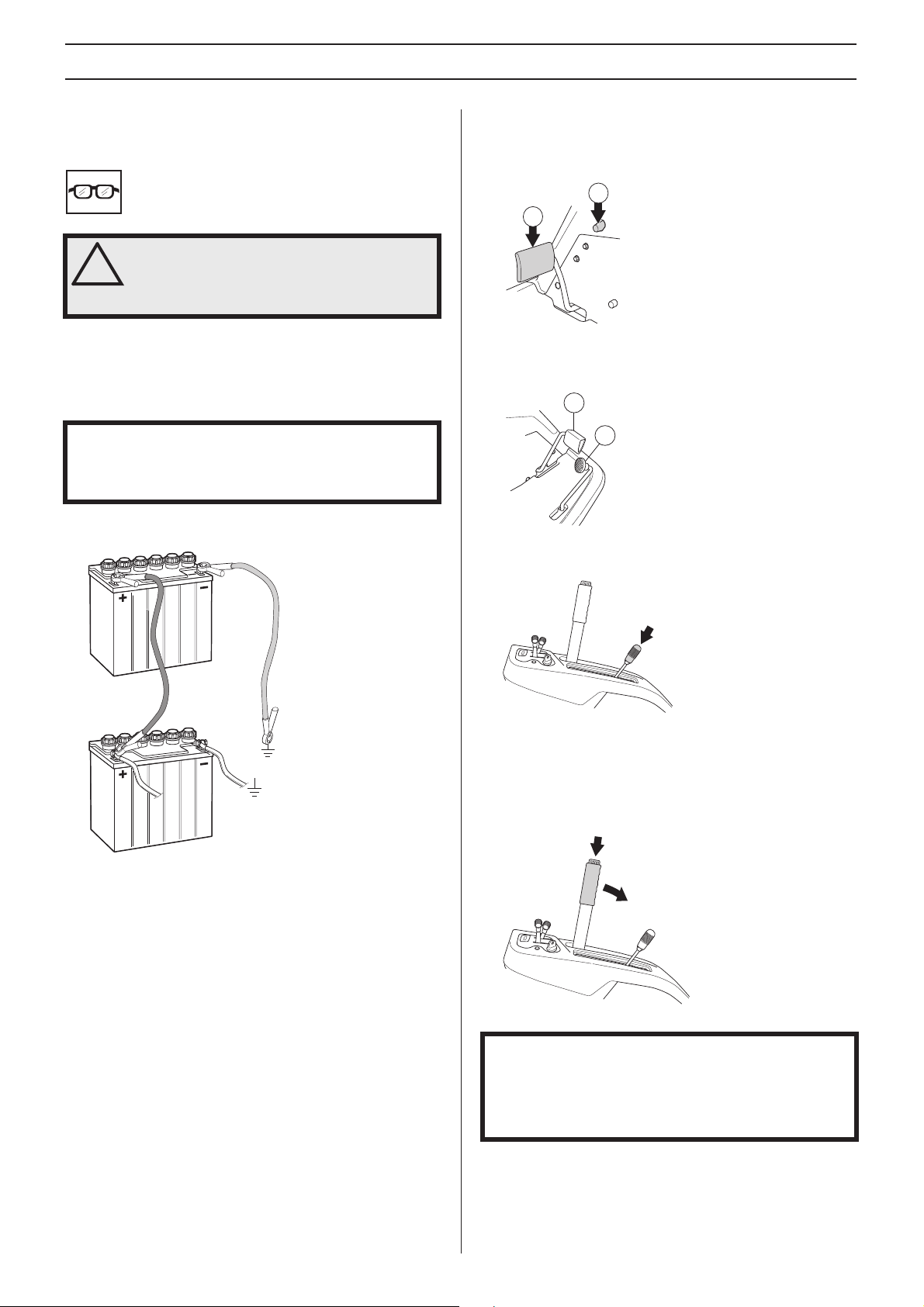
Driving
Starting the engine with a weak battery
WARNING! Lead-acid batteries produce
explosive gases. Avoid sparks, open flames
!
and smoking close to batteries. Al ways wear
protective glasses in the vicinity of batteries.
If the battery is too weak to start the engine, it should be
recharged.
When jump leads are used for emergency starting, follow the
procedure belo
IMPORT ANT INFORMA TION
12-volt system with negative earth. The other vehicle must
also have a 12-volt system with negative earth. Do not use
your Rider battery to start other vehicles.
Connecting the jump leads
w:
Your Rider is equipped with a
Driving the Rider
1 Release the parking brake by first pressing down the
parking brake pedal and then releasing it.
2
1
2 Carefully press do wn one of the pedals until the required
speed is obtained.
pedal (2) to drive backwards.
3 Select the required cutting height (1-10) with the cutting
height le
ver.
Pedal (1) is used to drive f orwards, and
1
2
• Connect each end of the red cable to the POSITIVE pole
(+) on each battery, exercise care not to short circuit any
of the ends against the chassis.
• Connect one end of the black cable to the NEGA TIVE pole
(-) on the fully charged batter
• Connect the other end of the black cable to a good
CHASSIS EAR
battery.
TH, away from the fuel tank and the
y.
Remove the cables in the reverse order
• The BLACK cable is removed from the chassis and then
the fully charged battery.
• Finally the RED cable from both batteries.
It is important that the air pressure in both front wheels is
equal, 60 kP
cutting height.
4 Press in the lock button on the lifting lever and lower the
cutting unit.
IMPORTANT INFORMATION
The life span of the drive belts is increased significantly if
the engine runs at a low speed when the blades are
engaged. Therefore apply full throttle first when the cutting
unit has been moved to the mowing position.
a / 0,6 bar / 8.5 PSI, to produce an even
English – 19
Page 20
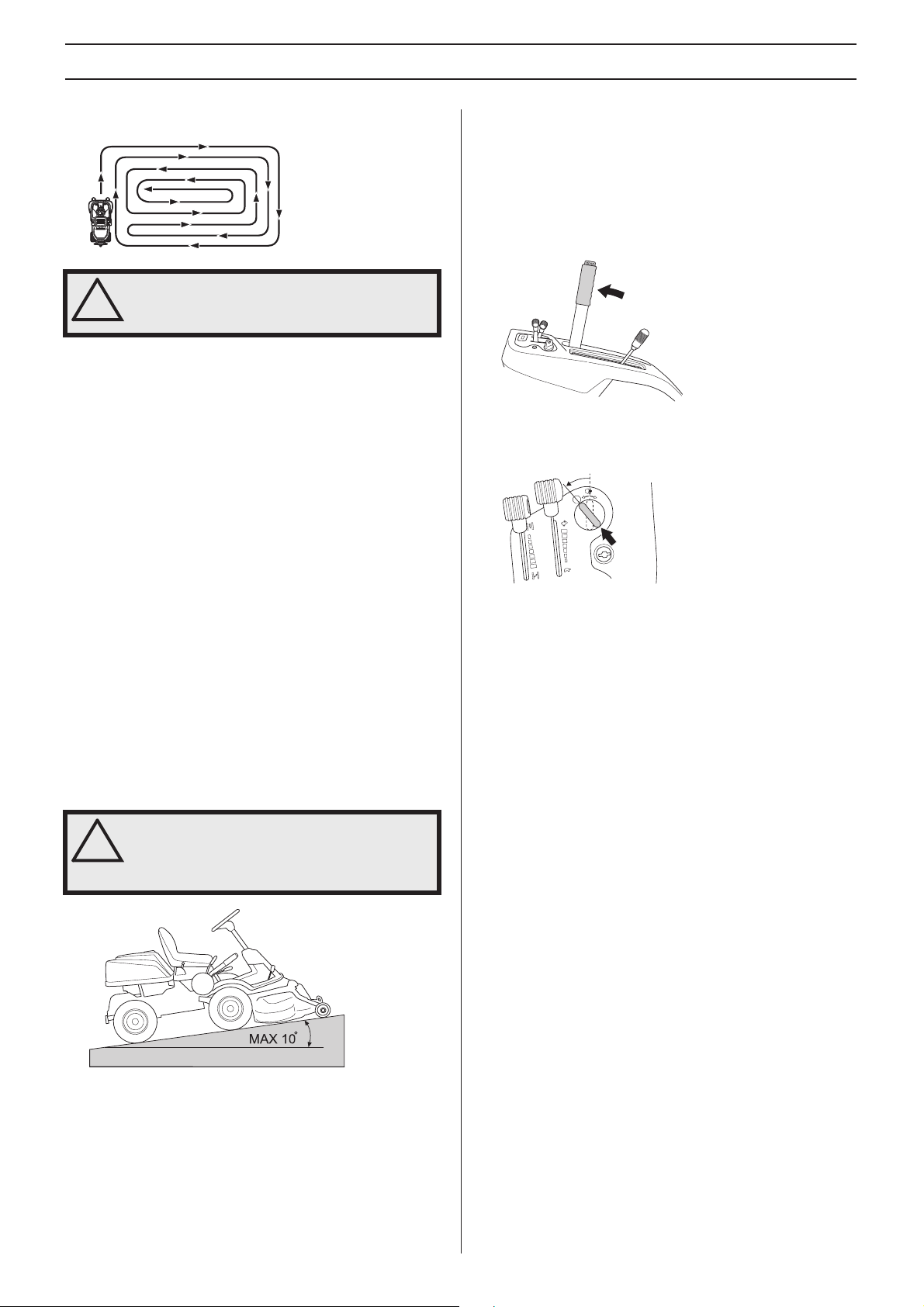
Driving
Cutting tips
WARNING! Clear the lawn from stones and
other objects which can be thrown out by
!
the blades.
• Localise and mark stones and other fixed objects to avoid
collision.
• Start with a high cutting height and reduce down until the
required mo
• The mowing result will be best with the highest permitted
engine speed, see technical data, (the b
rapidly) and low speed (the Rider moves slowly). If the
grass is not too high and thick, the driving speed can be
increased without noticeably depreciating the mowing
result.
• The best lawns are achieved if the grass is cut often.
wing becomes more uniform and the grass cuttings
Mo
become more evenly distributed over the surface. The
total time consumption is not greater since it is possible to
select a higher driving speed without inferior mowing
results.
• Avoid mowing a wet la wn. The mowing results will then be
poorer
• Hose down the cutting unit with water underneath each
time it is used.
service position.
• When the BioClip function is used, it is very important that
the mo
wing results are obtained.
lades rotate
.
The cutting unit should then be put in the
wing interval is not too long.
Stop the engine
Preferably allow the engine to idle for a minute to obtain
normal working temperature before stopping it if it has been
working hard. Avoid idling the engine for long periods, as
there is a risk of carbon build-up on the spark plugs.
1 Lift up the cutting unit b y pulling the lev er backw ards to its
ked position.
loc
2 Mo ve the throttle to the idle position. Turn the ignition key
to the ”ST
3 When the Rider is at a standstill, press down the parking
brake and push in the locking button.
OP”.
STOP
START
WARNING! Do not use the machine on
ground that slopes more than 10
!
slopes upwards and downwards, never
across. Avoid sudden changes in direction.
..
°°°°..
Mow
20 – English
Page 21

Maintenance
Maintenance schedule
The following is a list of the maintenance which should be conducted on the machine. F or those points not described in this manual,
visit an authorised service workshop.
Maintenance
Daily maintenance
before starting
At least once
a year
Maintenance
interval in hours
25 50 100 200
Cleaning X
Check the engine’s oil level X
Check the engine’s cooling air intake X
Check the fuel pump air filter X
Check the steering wires X
Check the battery X
Check the safety system X
Check nuts and screws O
Check for fuel and oil leakage. O
Clean around the silencer O
Clean the prefilter in the air filter
Change the engine oil
3, 4)
2)
X
X3X
3
Check the cutting deck X
Check the air pressure in the tyres. X
Lubricate the belt adjuster
Lubricate joints and shafts
1)
1)
X
X
Adjust the brake X
Check the V-belts O
Check the cooling fins on the hydrostatic transmission O
Checking the transmission oil level X
Checking and adjusting the choke wire X
Tighten the nuts and screws O
Checking and adjusting of throttle wire X
Clean the cooling fins on the engine and hydrostatic transmission
Replace the air filter’s prefilter and paper filter
2, 5)
2)
O
X X
Replace the fuel filter X
Replace the spark plug. X
Check the engine valve clearance
Check the need to change the oil
6)
6,7)
in the gearbox/hydraulic system O O
Change the oil filter X
Clean the combustion chamber
Decarburization and valve grinding
6)
6)
Check the synchronisation between the front and rear wheels6). O
Check the fuel hose. Replace if necessary .
1)
If the machine is used daily it should be lubricated twice a week.
hours. When operating with a heavy load or at high ambient temperatures, replace every 50 hours. 4)Replace the oil filter every 200 hours. 5)Replace the paper filter
annually or every 200 hours.
6)
Conducted by authorised service workshop. 7)Only 322T AWD first change after 8 hours
6)
2)
Maintenance and replacement are required more often in dusty conditions. 3)First change after 8
O
X = Described in this operator's manual
O = Not described in this operator's manual
!
21 – English
WARNING! No service procedures must be
conducted on the engine or cutting unit unless:
The engine is switched off.
The parking brake is applied.
The ignition key is removed.
The cutting unit is disengaged.
The ignition cables are removed from the plugs.
Page 22
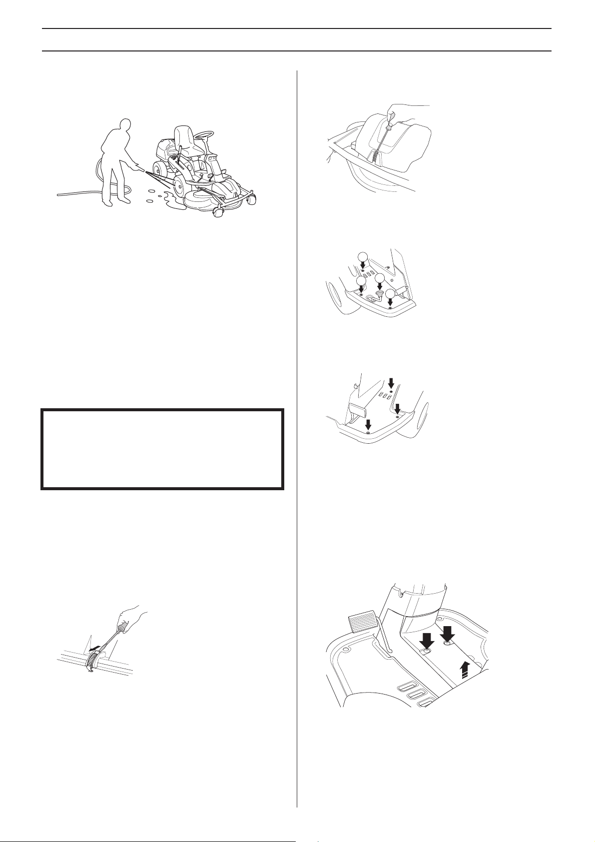
Maintenance
Cleaning
Clean the machine directly after use. It is much easier to wash
off grass cuttings before they dry.
Oily dirt can be removed using a cold degreasing agent.
Spr
ay on a thin layer.
Rinse at normal water pressure.
Do not direct the jet towards electrical components or
ings.
bear
Do not rinse hot surfaces such as the engine and exhaust
system.
It is recommended that you start the engine and run the
wer for a short period after cleaning, so that any remaining
mo
water is blown off.
Lubricate the machine if necessary after cleaning. Carry out
xtra lubrication when the bearings have been exposed to a
e
degreaser or a water jet.
Front cover
Release the clip on the front hood and lift off the fender.
Right-hand fender
Remove the accelerator knob (1), screws (2 and 3), and
remove the cover.
2
1
2
2
Left-hand fender
Remove the screws holding the wing co v er (2) and lift off the
cover.
IMPORTANT INFORMATION
Avoid using a high pressure washer or a steam cleaner.
There is a major risk of water penetrating into bearings and
electrical connections. Corrosion attack can result, which
will lead to running problems. Cleaning additives generally
aggravate the damage.
Removing of the machine hoods
Engine cover
The engine becomes accessible for service when the engine
cover is opened.
Fold the seat forward, loosen the snap lock under the seat
old the cover backwards.
and f
Checking and adjusting the steering wires
The steering is controlled by means of wires.
These can in time become slack, which implies that the
adjustment of the steer
Check and adjust the steering as follows:
1 Remo ve the frame plate by loosening the screws (2) and
lift the fr
ame plate by the rear edge.
ing becomes altered.
22 – English
Page 23
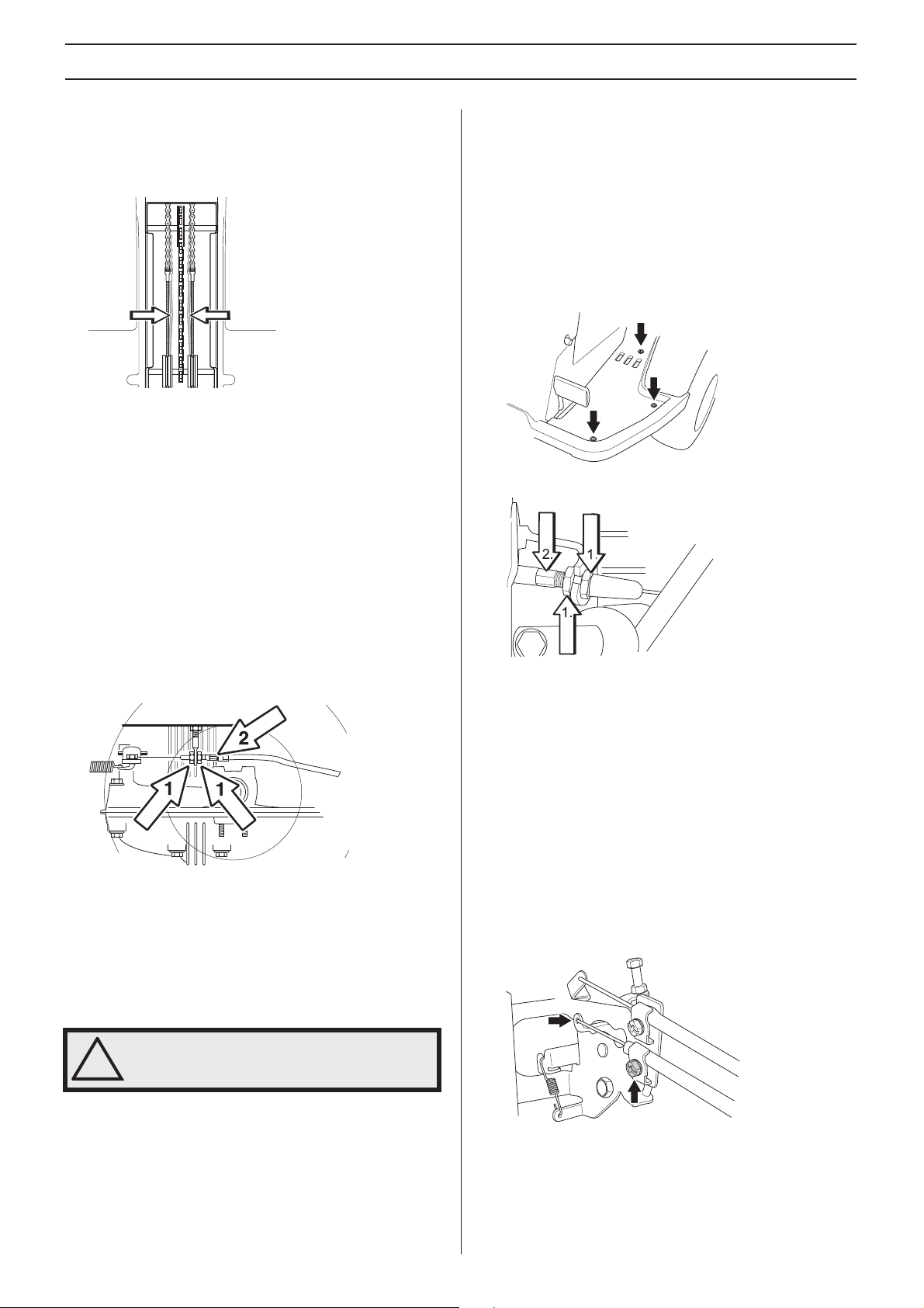
Maintenance
2 Check the tension of the steering wires by squeezing
them together by the arrows as illustrated. It should be
possible to push them together so that the distance
between them is half as much, without using unnecessary
force.
3 If necessary, the wires can be adjusted by tightening the
adjuster nuts on each side of the steering collar. Do not
over tighten the cables; they should only be drawn in
towards the steering collar.
Hold the cable, for example using an adjustable wrench,
so that it does not twist.
If the adjustment is only made on one side, the middle
position of the steer
Check the wire tension on completion of the adjustment
as per item 2.
ing will be affected.
Adjusting the parking brake Rider 322T AWD
Check that the parking brake is adjusted correctly by placing
the machine on a slope with the front and rear axles
disengaged.
Apply and lock the parking brake. When the machine does not
stand still, the par
the following.
1 Remove the left-hand wing cover.
2 Loosen the locking nuts (1).
king brake should be adjusted according to
Adjusting the parking brake Rider 220T
The parking brake is adjusted as follows:
1 Loosen the locking nuts (1).
2 Tension the cable using the adjuster screw (2) until the
y in the cable is taken up.
pla
3 Tighten the locking nuts (1) after adjustment.
4 The parking brake should be checked again after the
adjustment has been made
WARNING! A poorly adjusted parking brake
can result in reduced braking ability.
!
.
3 Tension the cable using the adjuster screw (2) until the
y in the cable is taken up.
pla
4 Tighten the locking nuts (1).
5 The brake should be checked again after adjustment
6 Assemble the left-hand wing cover.
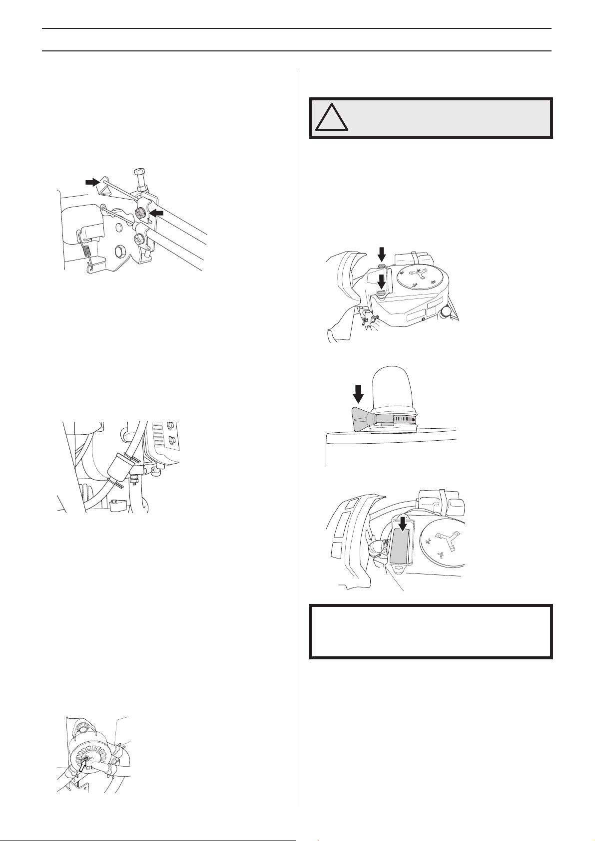
Checking and adjusting of throttle wire
Check that the engine responds to the throttle control and that
the correct engine speed is achieved at full throttle.
If doubts arise, contact your service representative.
If adjustment is necessary, adjust the lower wire as follows:
1 Loosen the clamping screw for the cable’s outer casing
ve the throttle to the full throttle position.
and mo
2 Chec k that the throttle wire is attached to the correct hole
in the lo
3 Pull the throttle wire casing to the far left and tighten the
clamping screw.
wer lever, see diagram.
English – 23
Page 24
Maintenance
Checking and adjusting the choke wire
If the engine is producing black smoke or is difficult to start
then the choke wire (upper wire) may be incorrectly adjusted.
If doubts arise, contact your service representative.
If it is necessary to adjust the choke, proceed as follows:
1 Release the clamping scre w that secures the wire casing
and set the chok
2 Chec k that the throttle wire is attached to the upper le v er,
see diag
3 Pull the choke wire casing to the far right and tighten the
clamping scre
ram.
e control to maximum choke.
w.
Replacing the air filter
WARNING! The exhaust system is hot. Let it
cool before starting to replace the air filter.
!
If the engine seems to lack power or does not run smoothly
this may be because the air filter is clogged. It is therefore
important to replace the air filter at regular intervals (see
Maintenance/Maintenance Schedule for the correct service
interval).
Replace the air filter as follows:
1 Loosen the knobs holding the filter cover in place and
ve it.
remo
2 Loosen the hose clip that holds the filter cartridge.
Replacement of fuel filter
Replace the fuel filter every 100 running hours (once per
season) or more frequently if it is clogged.
Replace the filter as follows:
1 Open the engine cover.
2 Mo v e the hose clips a w a y from the filter. Use a pair of flat
.
pliers
3 Pull off the filter from the hose ends.
4 Press the new filter into the ends of the hoses. If
necessar
facilitate connection.
5 Push the hose clips back on the filter and tighten.
y apply liquid detergent to the ends of the filter to
Checking the fuel pump’s air filter
Check regularly that the fuel pump’s air filter is free from dirt.
The filter can when necessary be cleaned with a brush.
3 Remove the filter cartridge from the filter housing.
IMPORTANT INFORMATION
Never run the engine without the air filter fitted.
The filters must not be oiled. They must be fitted dry.
4 Remo v e the foam rubber prefilter which is placed around
the filter car
5 Dry the pre-filter properly.
6 Clean the filter by knocking it with care against a hard
ace. Do not use compressed air to clean the filter.
surf
Replace the air filter if it is still dirty.
Always replace the paper filter every 200 hours.
7 Refit the pre-filter on the paper filter.
tridge and clean using a mild detergent.
24 – English
Page 25
Maintenance
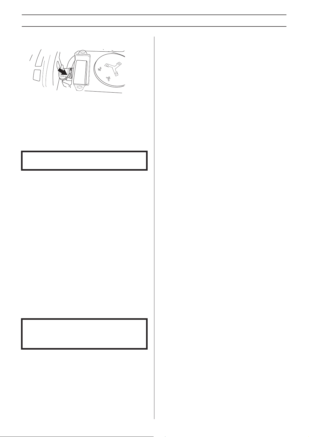
8 Pull the filter over the air hose and clamp the filter
cartridge in place with a hose clip.
9 Refit the air filter cover.
Ignition system
The engine is equipped with an electronic ignition system.
Only the spark plug requires maintenance.
For recommended spark plug, see Technical data.
IMPORTANT INFORMATION
Fitting the wrong spark plug type can damage the engine.
Replacing the spark plug
Check the safety system
The machine is equipped with a safety system that prevents
starting or driving under the following conditions.
The engine can only be started when:
• The cutting deck is raised and the parking brake is
applied.
The engine should stop when:
• The cutting deck is lowered and the driver rises from the
seat.
• The cutting deck is in its raised position, the parking brake
is not applied and the dr
Check daily to ensure that the safety system works by
attempting to star
above is not met. Change the conditions and try again.
t the engine when one of the conditions
iver rises from the seat.
1 Remove the ignition cable shoe and clean around the
spark plug.
2 Remove the spark plug with a 3/4” (16 mm) spark plug
ket wrench.
soc
3 Check the spark plug. Replace the spark plug if the
electrodes are b
damaged. Clean the spark plug with a steel brush if it is to
be reused.
4 Measure the electrode gap with a gapping tool. The gap
should be 0.75 mm/0.030”.
bending the side electrode.
5 Reinsert the spark plug, turning by hand to avoid
damaging the threads
6 Tighten the spark plug, once it touches the seating, with
the spar
washer is compressed. A used spark plug should be
turned 1/8 of a turn from the seated position. A new spark
plug should be turned a 1/4 turn from the seated position.
7 Replace the ignition cable shoe.
IMPORTANT INFORMATION
Inadequately tightened spark plugs can cause overheating
and damage the engine. Tightening the spark plug too
much can damage the threads in the cylinder head.
k plug spanner. Tighten the spark plug so that the
urned or if the insulation is cracked or
Adjust as necessary by
.
English – 25
Page 26
Maintenance
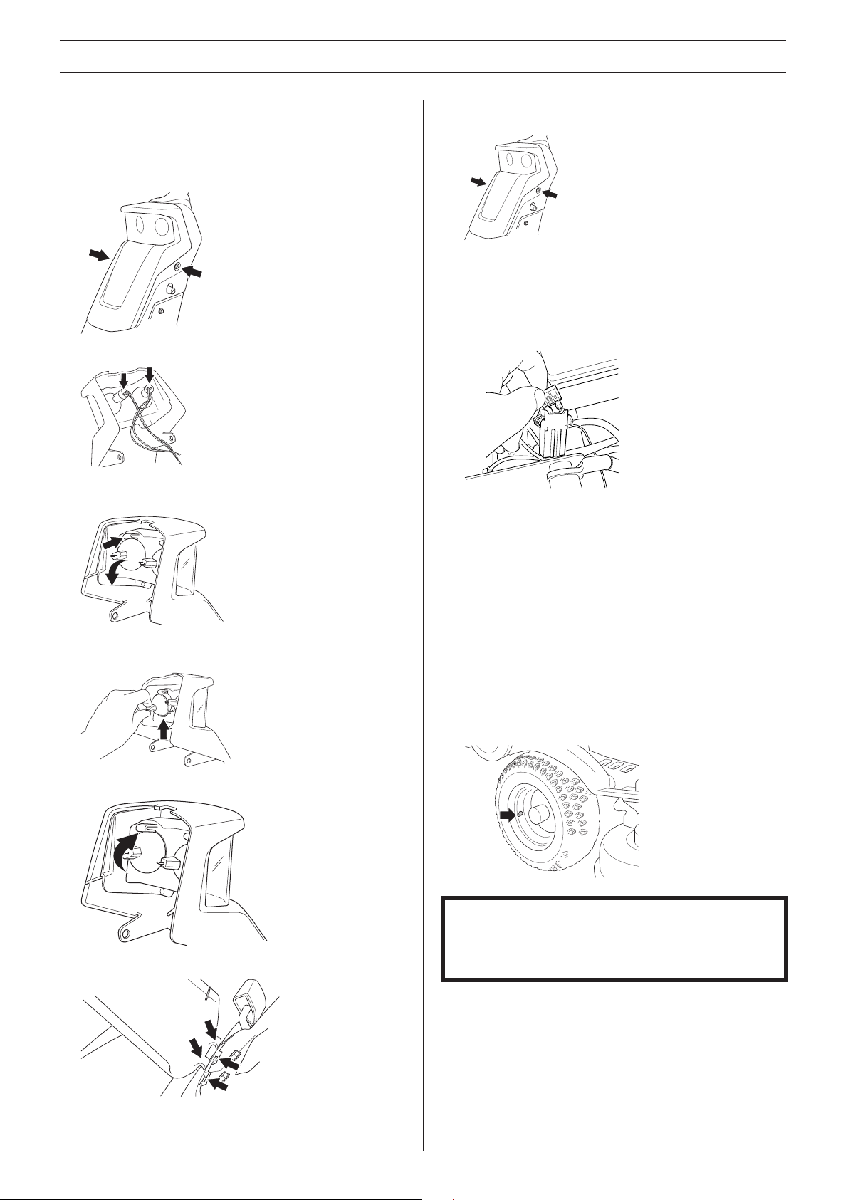
Replacing the light bulbs: 322T AWD
For information about the bulb type, see Technical Data.
1 Unscrew the two screws holding the cover on the power
vo housing. One screw on each side.
ser
2 Disconnect the cables from the bulbs.
3 Gently push in the locking mechanism and fold out the
lamps from their br
ackets.
7 Refit the cab les and screw the lamp holder on to the servo
housing.
Main fuse
The main fuse is placed in a detachable holder under the
battery case’s cover, in front of the battery.
Type: Flat pin, 15 A.
Do not use any other type of fuse when replacing.
A blown fuse is indicated by a burnt connector. Pull the fuse
from the holder when replacing.
The fuse is there to protect the electrical system. If it blows
again shor
which must be fixed before the machine can be put into
operation again.
tly after replacement, it is due to a short circuit,
4 Insert the new lamps in the lower slot on the lamp
housing.
5 Press the lamp in place in the locking bracket
6 Fit the lamp holder in the lo wer slots on the servo housing.
Checking the tyre pressure
The tyre pressure should be 60 kPa (0.6 bar / 9 PSI) all round.
To improve driving the pressure on the rear tyres can be
reduced to 40 kPa (0.4 bar/5.6 PSI). The maximum tyre
pressure is 100 kPa (1,0 bar/14 PSI).
IMPORTANT INFORMATION
Having the same air pressure in the tyres is important in
order to achieve the best possible performance as well as
to avoid damage to the machine
26 – English
Page 27
Maintenance
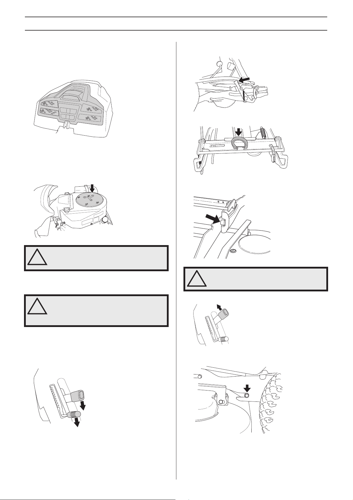
Checking the engine’s cooling air intake
Clean the air intake grille in the engine cover behind the
driver’s seat.
Open the engine cover.
Check that the cooling intake is free from leaves, grass and
t.
dir
A blocked cooling intake will interfere with the cooling of the
, which can damage the engine.
engine
3 Push the equipment frame down and place the catch
against the fr
4 Engage the belt in the belt holder.
5 Push the deck in and put the front guide plugs in the
rooves on the equipment frame, one on each side.
g
ame.
WARNING! The cooling air intake rotates
when the engine is running. Mind your
!
fingers.
Fitting the cutting head
WARNING! Wear protective glasses when
fitting the cutting unit. The spring which
!
tensions up the belt may break and cause
personal injury.
1 Place the Rider on a flat surface and apply the parking
brake.
2 Chec k that the lever f or setting the cutting height is in the
west position and that the lifting lever f or the cutting unit
lo
is in mowing position.
WARNING! Observe caution to avoid
trapping your hand.
!
6 Lift up the cutting unit
7 Push the unit in so that the interior plugs touch the bottom
of the equipment fr
ame’s grooves.
English – 27
Page 28
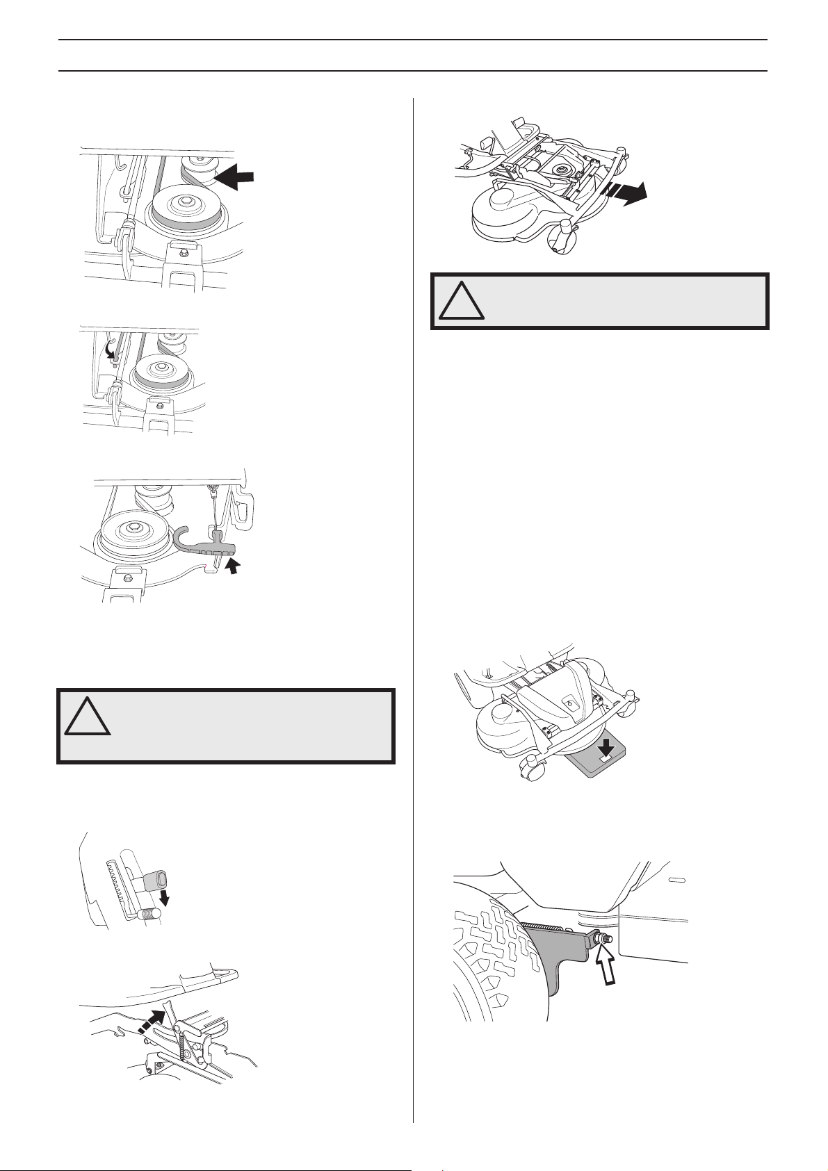
Maintenance
8 Fit the drive belt around the drive wheels of the cutting
unit. Mak e sure the belt is placed on the correct side of the
belt tensioner wheel.
9 Hook up the height adjustment strut.
10 Secure the collet spring.
11 Fit the front cover.
4 Pull out the cutting unit.
WARNING! Observe caution to avoid
trapping your hand.
!
Checking and adjustment of the cutting unit’s ground pressure
To achieve the best cutting results the cutting unit should
follow the underlying surface without pressing too hard
against it.
Pressure is adjusted using a screw and spring on each side
of the Rider
1 Chec k the air pressure in the tyres 60 kP a/0.6 kp/cm
PSI.
2 Place the machine on a flat surface.
3 Put the lifting lever in the mowing position.
4 Place a set of bathroom scales under the cutting unit’s
fr
necessary a block can be placed between the frame and
scales so that the support wheels do not bear any weight.
.
ame (front edge) so that it rests on the scales. If
2
/8.5
Removing the cutting unit
WARNING! Wear protective glasses when
dismantling the cutting unit. The spring
!
which tensions up the belt may break and
cause personal injury.
1 Carry out points 1-6 to put the cutting unit in the service
position, see Service position for the cutting unit.
2 Lower the cutting unit.
3 Open the unit catch.
5 Adjust the unit’ s ground pressure b y screwing in or out the
adjusting scre
sides. The ground pressure should be between 12 and 15
kg (26.5-33 lb).
ws located behind the front wheels on both
28 – English
Page 29
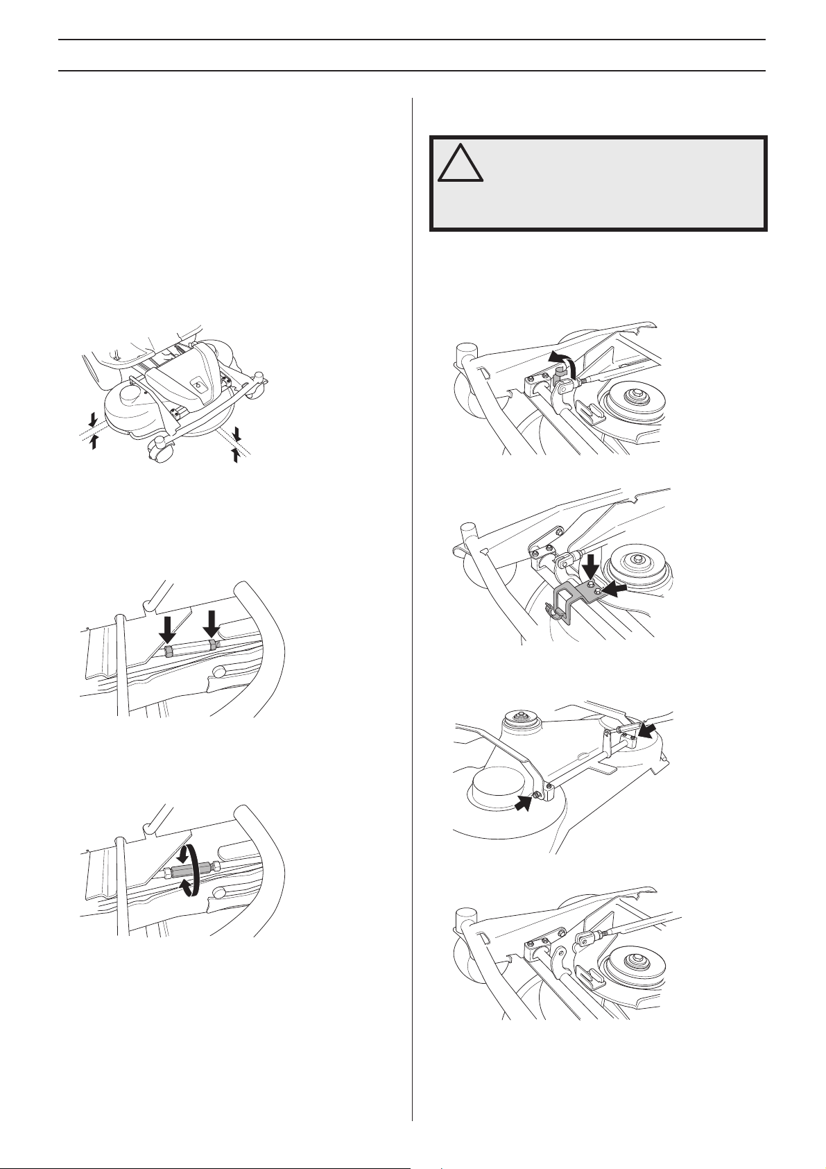
Maintenance
Checking the cutting unit’s parallelism
Check the cutting unit’s parallelism as follows:
2
1 Chec k the air pressure in the tyres 60 kP a/0.6 kp/cm
PSI.
2 Place the machine on a flat surface.
3 Put the lifting lever in the mowing position.
4 Measure the distance between the ground and the front
and rear edges of the cutting unit hood.
should have a slight slant, with the rear edge 2-4 mm (1/
8”) higher than the front edge.
The cutting unit
/8.5
Adjusting the parallelism of the cutting unit
Replacing the cutting unit belts
WARNING! Wear gloves to protect your
hands when working with the blades.
!
There is a risk of crush injuries when
working with the belt.
On these cutting units with collision-proof blades, the blades
are driven by one V-belt. Do as follows to change the V-belt:
1 Remove the cutting unit.
2 Open the lock for the track rod bolt.
3 Unscrew the bolts holding the unit frame bracket.
1 Remove the front hood and right-hand fender.
2 Undo the nuts on the lift strut.
3 Screw out (extend) the stay to raise the rear edge of the
co
ver.
Screw in (shorten) the stay to lower the rear edge of the
ver.
co
4 Remove the lock and pass the unit frame out.
5 Remove the two bolts on the unit frame.
6 Remove the bolt so the track rod is released in one end.
4 Tighten the nuts after adjustment.
5 On completion of the adjustment the unit’s parallelism
should be re-chec
6 Fit the right-hand fender and the front hood.
ked.
English – 29
Page 30
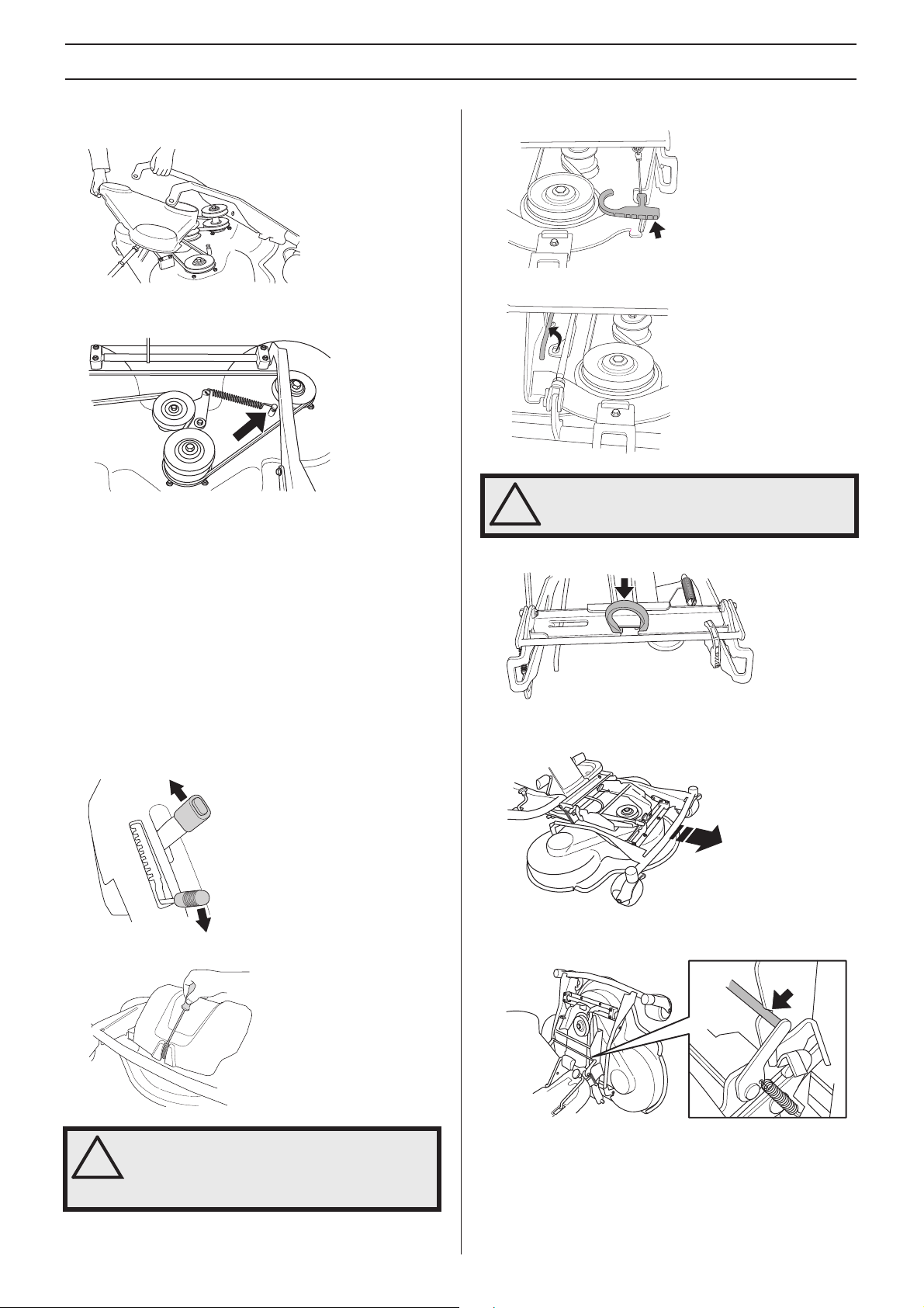
Maintenance
7 Remove the screws on the cutting cover. Lift the unit
frame and remove the cutting unit cover.
8 Loosen the spring that tensions the V-belt and pry off the
belt.
Assemble the parts in the reverse order.
Service position for the cutting unit
4 Disengage the spring for the drive belt tensioning wheel.
5 Loosen on the cutting height stay and place in the holder.
WARNING! Observe caution to avoid
trapping your hand.
!
6 Remove the drive belt and place it in the belt holder.
The cutting head can be placed in the service position to
provide easy access for cleaning, repairs and servicing. In the
service position the cutting unit is raised and locked in the
vertical position.
Placing in the service position
1 Position the machine on flat ground. Apply the parking
brake.
2 Set the cutting height control in the lo west position and lift
up the cutting unit.
3 Remove the front cover.
7 Grip the front edge of the unit and pull forwards until it
stops
.
8 Lift the unit until it stops and a clic king sound is heard. The
unit loc
ks automatically in the vertical position.
!
30 – English
WARNING! Wear protective glasses when
dismantling the cutting unit. The spring
which tensions up the belt may break and
cause personal injury.
Page 31
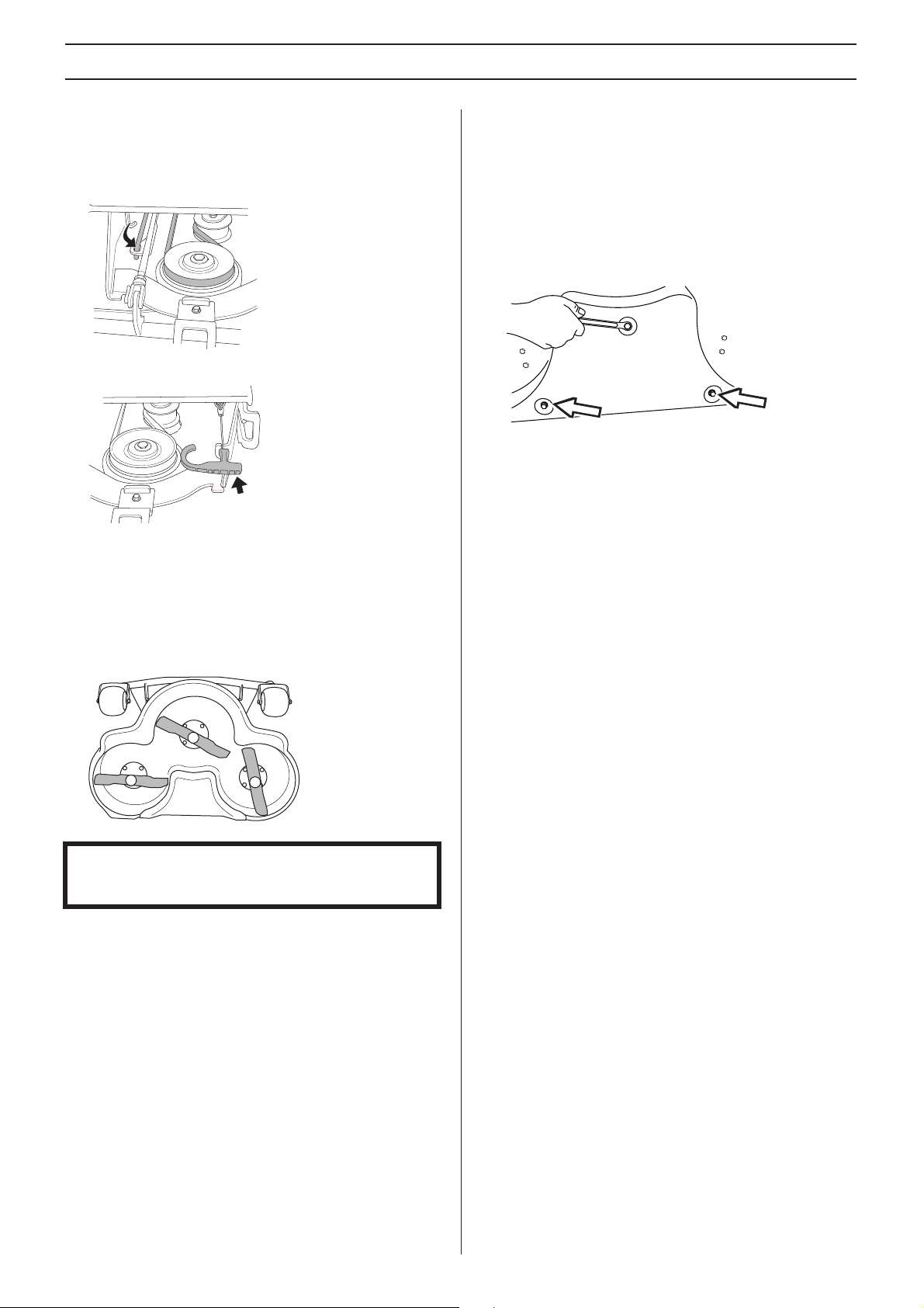
Maintenance
Restoring from service position
1 Grip the front edge of the unit and loosen the lock, fold
down and slide in the unit.
2 Replace the cutting height stay and the belt.
3 Tension the belt with the belt adjuster.
4 Fit the front cover.
Removing the BioClip plug
To change a Combi unit from BioClip function to cutting unit
with rear ejection, remove the BioClip plug located under the
unit with three screws.
1 Put the unit in the service position, see Placing in the
vice position.
ser
2 Remove the three screws holding the BioClip plug, and
ve the plug.
remo
3 Tip: Fit three full-thread screws M8x15 mm in the screw
holes to protect the threads
4 Replace the unit in normal position.
Fit the BioClip plug in the reverse order.
.
Checking the blades
To achieve the best mowing results it is important that the
blades are undamaged and well-sharpened.
Check that the blades’ attachment screws are tight.
IMPORT ANT INFORMATION Replacing or sharpening the
blades should be conducted by an authorised service
workshop.
The blades should be balanced after sharpening.
Damaged blades should be replaced when hitting obstacles
that result in a breakdo
whether the blade can be sharpened or must be replaced.
wn. Let the service centre assess
English – 31
Page 32
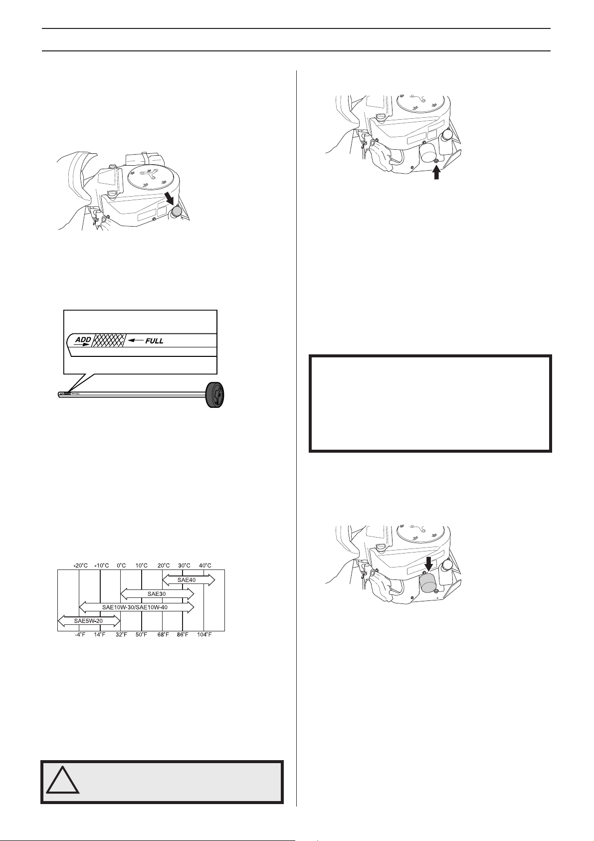
Lubrication
Checking the engine’s oil level.
Check the oil level in the engine when the Rider stands
horizontal with the engine switched off.
Open the engine cover.
Loosen the dipstick, pull it up and wipe it off.
Now insert the dipstick again,
Pull the dipstick out again and read the oil level.
The oil level should be between the markings on the dipstick.
vel is approaching the ADD mark, top up the oil to the
If the le
FULL mark on the dipstick.
without tightening it.
1 Place a container underneath the engine’s left oil drain
plug.
2 Remove the dipstick. Remove the drain plug from the
s left side.
engine’
3 Let the oil run out into the container.
4 Fit the drain plug and tighten it.
5 If necessary fill so that the oil comes up to the FULL mark
on the dipstic
dipstick sits in. See Checking the engine’s oil level for
filling instructions. The engine holds 1.5 litres (1.6 USqt)
when the oil filter is not replaced and 1.7 litres (1.8 USqt)
of oil when the oil filter is replaced.
6 Run the engine w arm, then check that there is no leakage
from the oil plug.
k. The oil is topped up through the hole the
The oil is topped up through the hole the dipstick sits in. Fill
the oil slo
Tighten the dipstick correctly before starting the engine. Start
and r
Turn off the motor. Wait 30 seconds and check the oil level. If
necessary fill so that the oil comes up to the FULL mark on
the dipstick.
The following oil classes are recommended:
• API Service Class: SF, SG, SH and SJ
Choose an oil with viscosity according to the temperature
anges in the figure:
r
Do not mix different types of oil.
wly.
un the engine at idling speed for approx. 30 seconds.
Replacing the engine oil
The engine oil should be changed the first time after 8 hours
running time. It should then be changed after e very 100 hours
of running time.
When operating with a heavy load or at high ambient
atures, replace every 50 hours.
temper
IMPORTANT INFORMATION
Used engine oil, antifreeze etc. is a health hazard and must
not be disposed of on the ground or in nature; it should
always be disposed of at a workshop or appropriate
disposal location.
Avoid skin contact; wash with soap and water in case of
spills.
Changing the oil filter
The oil filter must be replaced after every 200 hours running
time. Turn the old oil filter anti-clockwise to remove. If
necessary, use a filter remover.
Lightly lubricate the rubber seal on the new oil filter using new
oil.
Fit the oil filter by turning clockwise. Turn by hand until the
rubber seal is seated. Now tighten a further half turn.
Fill with new oil according to Checking the engine’s oil level.
Start the engine and let it idle for about 3 minutes. Now stop
it and check for signs of leakage. Fill with oil to compensate
for the oil held in the new oil filter.
!
32 – English
WARNING! Engine oil can be very hot if it is
drained directly after stopping the engine.
Allow the engine to cool somewhat first.
Page 33
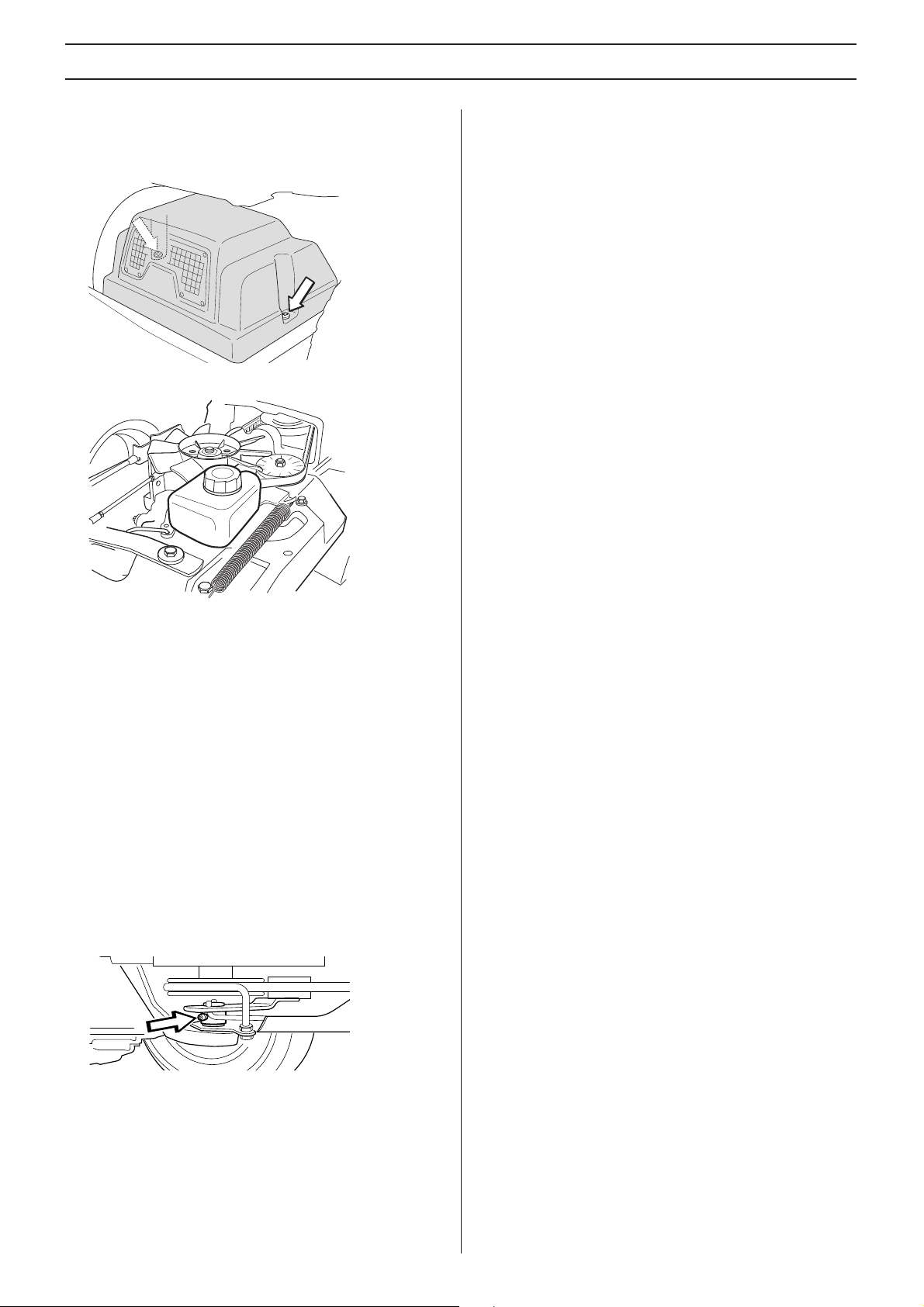
Lubrication
Checking the transmission oil level
1 Remove the transmission cover. Undo the two screws
(one on each side) and lift off the transmission cover.
2 Check that there is oil in the transmission’s oil tank.
General lubrication
All joints and bearings are lubricated using molybdenum
disulphide grease during manufacture. Continue to lubricate
using the same type of grease *. Lubricate the steering and
control wires using engine oil.
Carry out this lubrication regularly; with daily use, the
machine should be lubr
*Grease from well-known brand names (petrochemical
companies
important property is that the grease provides good
protection against corrosion.
, etc.) usually maintains a good quality. The most
icated twice weekly.
Rider 220T Fill if necessary with engine oil SAE 10W/40
(class SF–CC).
Rider 322T AWD Fill if necessary with oil Synthetic
10W/50
The oil and filter should be changed by an authorised service
representativ
Work on the system entails particular demands on
cleanliness and the system m
machine is used.
e, as described in the Workshop Manual.
ust be vented before the
Lubricating the belt adjuster
The belt adjuster should be lubricated regularly using good
quality molybdenum disulphide grease*.
Lubricate using a grease gun, 1 nipple from the right-hand
side under the engine’
out.
s lower belt pulley , until g rease is forced
With daily use, lubrication should be carried out twice weekly .
English – 33
Page 34

Troubleshooting schedule
Problem Procedure
Engine does not start
Starter motor does not turn over the
engine
Engine does not run smoothly Faulty spark plug.
There is no fuel in the fuel tank
Spark plug defective
Faulty spark plug connections or interchanged cables
Dirt in the carburettor or fuel line
Starter motor does not turn over the engine
Battery flat
Bad contact between the cable and battery
Lift lever for cutting unit in wrong position
Main fuse blown.
Ignition lock faulty
Brake not activated.
Faulty starter motor
Carburettor incorrectly set
Air filter clogged
Fuel tank vent blocked
Ignition key defective
Dirt in the carburettor or fuel line
Choking or incorrectly adjusted throttle cable
Engine seems to have no power Air filter clogged
Spark plug defective
Dirt in the carburettor or fuel line
Carburettor incorrectly set
Choking or incorrectly adjusted throttle cable
Engine overheats Engine overloaded
Spark plug defective
Air intake or cooling flanges blocked
Fan damaged
Too little or no oil in engine
Ignition defective
Battery does not charge One or more battery cells faulty
Poor contact on the battery terminal cable connectors
Machine vibrates Blades are loose
Engine is loose
One or more blades unbalanced, caused by damage or poor balancing after sharpening
Uneven mowing Blades blunt
Long or wet grass
Cutting unit skew
Grass blockage under hood
Different tyre pressures on right and left sides
Over-speeding
Engine speed too low
Drive belt slipping
English – 34
Page 35
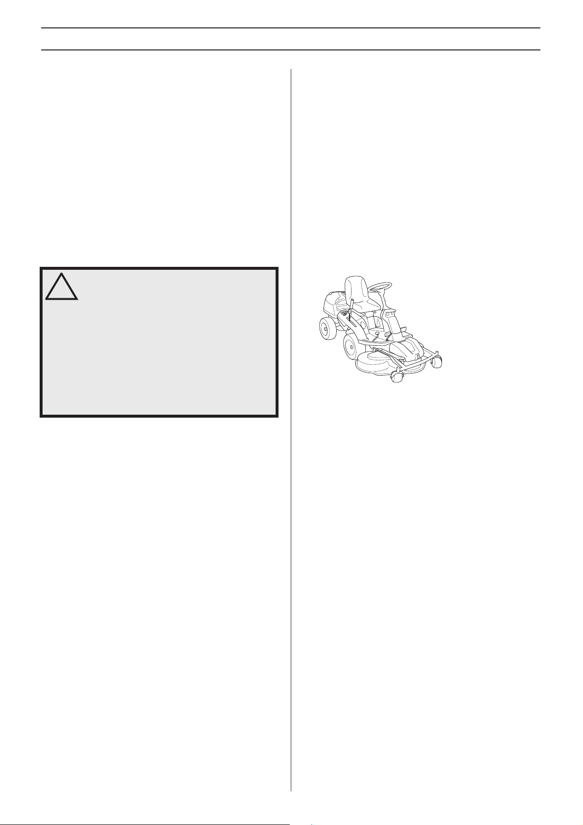
Storage
Winter storage
At the end of the season, or if the machine is going to stand
idle for more than 30 days, it should immediately be made
ready for storage. Fuel which is left to stand for long periods
(30 days or more) can leave tacky deposits which can block
the carburettor and interfere with the engine.
Fuel stabiliser is an acceptable alternative to avoid tacky
deposits dur
stabiliser is not necessary since this fuel is stable. However,
one should avoid changing from standard to alkylate petrol
since sensitive rubber parts can harden. Add stabiliser to the
fuel in the tank or the storage container. Always use the
mixing ratios indicated by the manufacturer. Run the engine
for at least 10 minutes after adding the stabiliser so that it will
reach the carburettor. Do not empty the fuel tank and
carburettor if stabiliser has been added.
!
ing storage. If alkylate petrol (Aspen) is used
WARNING! Never store a machine with fuel
in the tank indoors or in poorly ventilated
spaces where fuel vapour can come in
contact with open flames, sparks, or a pilot
light such as in a boiler, hot water tank,
clothes drier, etc. Exercise caution when
handling fuel. It is highly inflammable, and
careless use can cause serious injury and
damage to property. Drain off the fuel in an
approved container outdoors and well clear
of naked flames. Never use petrol for
cleaning purposes. Use degreasing agents
and hot water instead.
Guard
There is a cover to protect your machine during storage or
transport. Contact your dealer for a demonstration
Service
Low season is the most suitable time to perform a service or
overhaul of the machine in order to ensure high function
safety during high season.
When ordering spare parts state your machine’s purchase
ear, model, type, and serial number.
y
Always use genuine parts.
Annual inspection or tuning by an authorised service
orkshop is a good way of getting the best out of your
w
machine the next season.
To prepare the machine for storage follow these instructions:
1 Carefully clean the machine , especially under the cutting
Touch-up paint damage to avoid rust.
unit.
2 Inspect the machine for worn or damaged parts and
tighten loose scre
3 Change the engine oil, and take care of the waste oil.
4 Empty the fuel tank. Start the engine and run it until the
urettor is emptied of fuel.
carb
5 Remo ve the plugs and pour about a tab lespoon of engine
oil into each cylinder
the oil and screw the plugs back on.
6 Grease all grease nipples, joints and axles.
7 Remove the battery. Clean it, charge it, and store it in a
cool place
8 Store the machine in a clean and dry place and cover it
ver for extra protection.
o
.
ws and nuts.
. Pull round the engine to distribute
English – 35
Page 36

Technical data
Dimensions Rider 220T Rider 322T AWD
Length without cutting unit, mm/ft 2020/6,61 2020/6,61
Width without cutting unit, mm/ft 890/2,92 890/2,92
Height, mm/ft 1150/3,77 1150/3,77
Operating weight with cutting deck, kg/lb 285-288-301/628-635-664 308-311-324/679-686-714
Wheel base, mm/ft 887/2,91 887/2,91
Track width, front, mm/ft 712/2,34 712/2,34
Track width, rear, mm/ft 627/2,06 627/2,06
Tyre dimensions 16 x 6,50 x 8 16 x 6,50 x 8
Air pressure, rear - front, kPa / bar / PSI 60 (0,6/8,5) 60 (0,6/8,5)
Cutting width, cm/inch 103-112-122 / 41-44-48 103-112-122 / 41-44-48
Engine
Brand / Model Brigs&Stratton 7220 Endurance Twin Brigs&Stratton 7220 Endurance Twin
Nominal engine output, kW (see note 1) 12,6 12,6
3
Displacement, cm
Fuel, minimum octane grade lead-free 87 87
Tank volume, litres/USqt 12/13 12/13
Oil
Oil volume incl. filter 1,7/1,8 1,7/1,8
Oil volume excl. filter, litres/USqt 1,5/1,6 1,5/1,6
Starting Electric start 12V Electric start 12V
Max.motor speed, r/min 3000
Electrical system
Type 12 V, negative earthed 12 V, negative earthed
Battery 12 V, 24 Ah 12 V, 24 Ah
Spark plug EMS Platinum EMS Platinum
Electrode gap, mm/inch 0,75/0,030 0,75/0,030
Lights Osram, 2X12V 20W Osram, 2X12V 20W
Vibration levels
(see note 2)
Vibration level on the steering wheel, m/s
Vibration level in the seat, m/s
Transmission
Brand T uff Torq K46 K 574 KTM 10L
Oil, class SF-CC SAE 10W/40 SAE 10W/50 Synthetic
Cutting unit
Type Combi 103 Combi 103
Note 1: The power rating of the engine indicated is the average net output (at specified rpm) of a typical production engine for the engine model measured to SAE
standard J1349/ISO1585. Mass production engines may differ from this value. Actual power output for the engine installed on the final machine will depend on the
operating speed, environmental conditions and other values.
Note 2: Vibration level according to EN 836. Reported data for vibration level has a typical statistical dispersion (standard deviation) of 0.2 m/s2 (steering wheel) and
2
(seat).
0.8 m/s
/cu.in 656/40 656/40
± 100 3000 ± 100
2
2,5 2,5
2
0,7 0,7
Combi 112 Combi 112
SD 48
SD 48
English – 36
Page 37

Technical data
Cutting unit Combi 103 Combi 112 SD 48
Cutting width, mm/inch 1030 / 41 1120 / 44.1 1220 / 48
Cutting heights, 10 positions, mm/inch 25-75/0.98-2.95 25-75/0.98-2.95 25-75/0.98-2.95
Blade length, mm/inch 388/15.28 420 / 16,5 423 / 16,7
IMPORT ANT INFORMATION When the service life of this product has been served and it is no longer used it should be returned
to the dealer or to an applicable station for recycling.
IMPORTANT INFORMATION We reserve the right to change specifications and designs without prior notice so as to implement
improvements.
Note that no legal claims are valid on the basis of information in this manual.
Use only genuine parts for repairs. The warranty is not valid if non genuine parts are used.
37 – English
Page 38

Page 39

Page 40

´®z+VW,¶6%¨
Original instructions
1154551-95
´®z+VW,¶6%¨
2012-05-04
 Loading...