

Page 1

PT 26D
Operator´s manual
English
Page 2

1
Contents
Chapter 1:Introduction ................................................. 3
Congratulations ........................................................ 3
Driving and Transport on Public Roads ...................3
Towing ..................................................................... 3
Use ........................................................................... 4
Proper Service .........................................................5
Serial Number .......................................................... 6
Chapter 2:Symbols and Decals................................... 7
Chapter 3:Safety Instructions.................................... 11
General Use ...........................................................11
Driving on slopes ...................................................16
Children .................................................................. 18
Maintenance .......................................................... 19
Transport ................................................................ 25
Environment protection .......................................... 26
User responsibility .................................................. 28
Chapter 4:Presentation .............................................. 29
1-2. Speed control .................................................. 34
3. Parking brake .....................................................35
4. Control panel ...................................................... 35
5-9. Seat ................................................................35
10. Steering wheel and steering wheel console ..... 37
11. Differential Lock ...............................................38
12. Adjusting the cutting height ..............................38
13. Fuelling ............................................................39
21-37. Controls on the control panel ......................40
21. Control lever hydraulics ...................................40
22. Switch for operation of cutting unit ...................42
23. Switch for extra hydraulic function
(hydraulic kit option) ...............................................42
24. Push button for horn (traffic kit option) .............43
25. Indicators (traffic kit option) ..............................43
26. Starter switch ...................................................44
27. Headlight ..........................................................44
28. Throttle control .................................................45
29. High speed .......................................................45
30. Weight transfer .................................................46
31. Rotating warning light (traffic kit option) ...........46
32. Parking lights (traffic kit option) ........................47
33. Spare ................................................................47
34-35.Power outlet .................................................47
36. Chronometer ....................................................48
40-51. Warning lamps ............................................48
49. Lever for steering wheel console angle ............49
Adjusting the steering wheel setting .......................49
Cooling system .......................................................50
Cutting unit .............................................................54
Accessories ............................................................55
Towing ....................................................................55
Chapter 5:Driving........................................................ 57
Mowing Tips ..........................................................57
Before Starting .......................................................59
Starting the engine .................................................61
Driving the machine ................................................66
Braking ...................................................................68
Cutting the engine ..................................................69
Bleeding in the event of fuel stoppage. ..................70
Engine stop ............................................................70
Chapter 6:Maintenance .............................................. 71
Maintenance Schedule ...........................................71
Cleaning .................................................................77
Removing the machine’s covers ............................79
Checking radiatorgrilles ..........................................79
Cleaning the radiator's heat exchanger ..................80
Adjusting the pump and generator drive belts ........80
Replacing the pump and generator drive belts .......81
Checking and adjusting the throttle control ............81
Checking the exhaust system ................................82
Adjusting the parking brake ....................................83
Page 3

2
Contents
Servicing the air filter ..............................................84
Cleaning the cyclone filter ......................................84
Replacing the air filter .............................................85
Bleeding the fuel system ........................................86
Servicing the fuel filter ............................................87
Checking the Tyre Pressures .................................88
Servicing the battery ...............................................89
Fuses ......................................................................90
Checking the Safety System ..................................92
Replacing the bulb in the headlight ........................93
Light setting ............................................................94
The Cutting Unit Components ................................95
Attaching and removing the cutting unit .................95
Side shifting the cutting unit ...................................96
Setting the cutting height and tilt angle ..................99
The Cutting Unit’s Service Position ......................101
Cutting Unit Model ................................................103
Checking the Blades ............................................104
Replacing the power take-off belts .......................105
Adjusting the power take-off belts ........................106
Replacing the cutting unit belt ..............................107
Removal of BioClip Plug .......................................109
Chapter 7:Lubrication............................................... 111
Lubrication Schedule ............................................111
General .................................................................112
Lubricating the cables ..........................................112
Accessories ..........................................................113
Lubricating in Accordance with the Lubrication
Schedule ..............................................................113
Chapter 8:Trouble Shooting Guide .........................127
Chapter 9:Storage.....................................................133
Winter Storage .....................................................133
Service .................................................................135
Chapter 10:Electrical system...................................137
Chapter 11:Hydraulic System ..................................138
Chapter 12:Fuel system ...........................................141
Technical Data........................................................... 143
Design standards......................................................149
WARNING:
Failure to observe the safety instructions or
operating instructions can result in serious injury
to the operator or others. The machine’s owner
must understand the importance of these
instructions and only allow operators who are
trained on the machine and who understand the
instructions to handle the machine. The operator
must, with full judgement, handle the machine with
care and must not be under the influence of alcohol,
drugs or medication that affects judgement.
Page 4

3
Introduction
Chapter 1: Introduction
Congratulations
Thank you for purchasing a Husqvarna PT 26D. Husqvarna PTs have been designed according to a unique concept
with a front mounted cutting unit and Husqvarna's unique rear wheel steering. The machine is built to give maximum
efficiency even in small and difficult areas. Collected controls and a hydrostatic transmission controlled by pedals
also contribute to the machine’s performance.
This Operator’s Manual is a valuable document. Following the instructions (use, service, maintenance, etc.) can
considerably increase the service life of your machine and even increase its resale value.
When you sell your machine, make sure to give the operator’s manual to the new owner.
A service journal is available for the machine. Ensure that service and repair work is documented. A well-kept
service journal reduces service costs for the season-based maintenance and affects the machine’s resale value.
Take the service journal along when the machine is taken to the workshop for service.
Driving and Transport on Public Roads
Check applicable road traffic regulations before driving and transport on public roads. You should always use
approved load retainers during transport and ensure that the machine is well secured.
Towing
The PT 26D is equipped with hydrostatic transmission and a bypass valve must be used when towing.
Page 5

4
Introduction
Use
This machine is designed to mow grass on ordinary lawns and other open and level ground surfaces without
obstacles such as stones, stumps and the like. All other types of use are incorrect. The manufacturer’s instructions
with regard to driving, maintenance and repair must be followed precisely, even when the machine is equipped with
special accessories supplied by the manufacturer for which operating instructions accompany the delivery.
This machine should be operated, serviced and repaired only by persons who are familiar with its particular
characteristics and who are acquainted with the relevant safety instructions.
Accident prevention regulations, other general safety regulations, occupational safety rules, and traffic regulations
must be observed.
Unauthorised modifications to the design of the machine may absolve the manufacturer from liability for any
resulting personal injury or property damage.
Page 6

5
Introduction
Proper Service
Husqvarna’s products are sold all over the world and only by specialised retail traders offering complete service.
This ensures that you as a customer receive only the best support and service. Before the product is delivered, the
machine has, for example, been inspected and adjusted by your dealer, see the certificate in the Service Journal.
When you need spare parts or support concerning service, warranty issues, etc., please consult the following
professional:
This operator’s manual belongs to the
machine bearing serial number:
Engine Transmission
Page 7

6
Introduction
Serial Number
The serial number can be found on the printed plate attached on the right-hand side under the seat. The plate
includes the following information:
• The machine’s type designation.
• Weight.
• The manufacturer's type number.
• The machine’s serial number.
• Manufacturer.
Please state the type designation and serial number when ordering spare parts.
The engine’s serial number is on the engine block above the injection pump.
Please state this when ordering spare parts.
The hydraulic pump and hydraulic motors are equipped with rating plates that indicate type designation and serial or
manufacture numbers.
Please state these when ordering spare parts.
Page 8
7
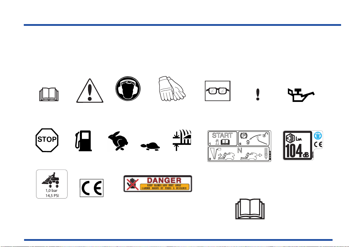
Starting instructions:
Activate the parking brake
Read the operator’s manual
Hydrostat pedals in neutral
position
Fuel Fast
Engine off
Oil level
Cutting
Use protective
gloves
Use hearing
protection
Warning
Tyre
pressure
Read the
operator's manual
Use protective
glasses
CE conformity
marking
Slow
Danger. Keep your hands and
feet away
Noise emission to
surroundings in
accordance with the
directive of the
European Community.
The machine’s
emission is indicated in
the TECHNICAL DATA
chapter and on the
decal.
Poisonous
Hazardous to
health
Symbols and Decals
Chapter 2: Symbols and Decals
These symbols are found on the machine and in the operator’s manual. Symbols for control units and warning lamps
are displayed in chapter “Presentation”, see page 42 and following pages.
Study them carefully so you understand their significance.
Page 9
Symbols and Decals
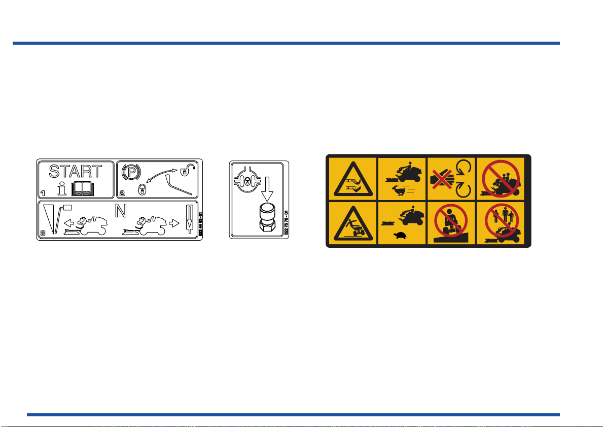
Read the
Operator's manual
8
Parking brake
Warning!
Rotating
blades
Only for
attached
cutting unit
Do not insert
your hands
or feet under
the cover
when the
engine is
running
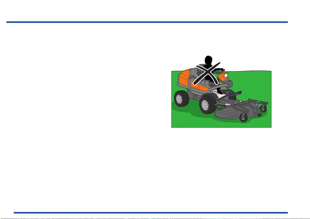
Never carry
passengers
on the
machine
or on its tools.
1
0
61 93 445
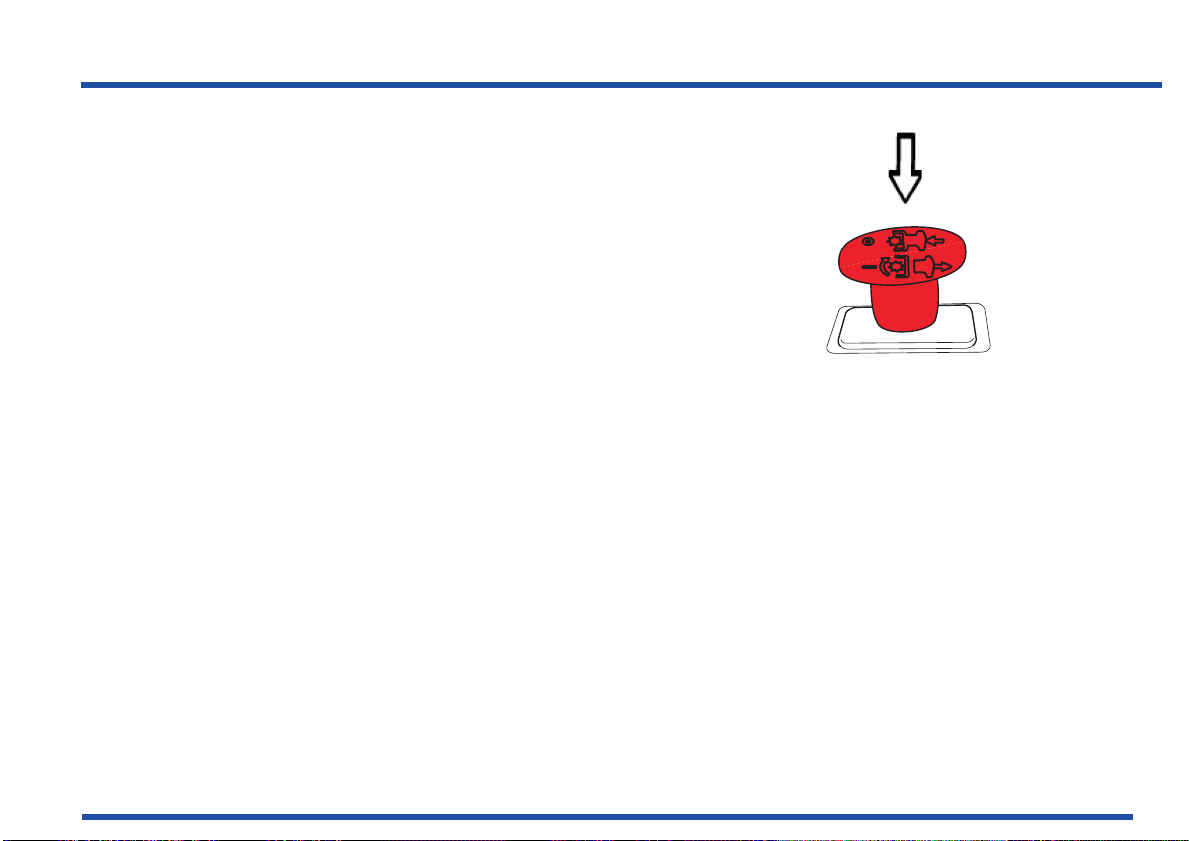
Pedal forwards
Pedal backwards
Differential lock
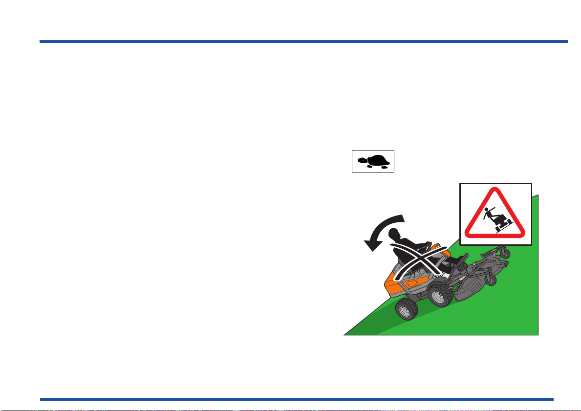
Warning!
Risk of the
machine
overturning
Drive very
slowly
without the
cutting unit
Never
drive
directly
across a
slope
Never use the
machine if
there are
people,
especially
children, or
pets, in the
immediate
vicinity.
Page 10

9
Symbols and Decals
WARNING:
Xxxxxx x xxxx xxxxx xxxxx xxxxx Xxxxxxxxxxx xxx
xxxxxx. Xxxx xxxxxxx xxx xx xxxx
Used in this publication to notify the reader of a risk of serious personal injury , particularly if the reader should
neglect to follow instructions given in the manual.
Page 11

10
Symbols and Decals
IMPORTANT INFORMATION:
Xxx xxx xxxx xxxxxxxxx xxx xxxxx xxx xxxx xx
xxxxx xx xxxxx. Xxx xxxxxxxx xx x x xxxxxxx xx
xxxx xxxx.
Used in this publication to notify the reader of a risk of material damage , particularly if the reader should neglect to
follow instructions given in the manual. Used also when there is a potential for misuse or misassembly.
Avoid hosing the decals with high pressure washers. Replace damaged decals before the machine is used.
Page 12
11
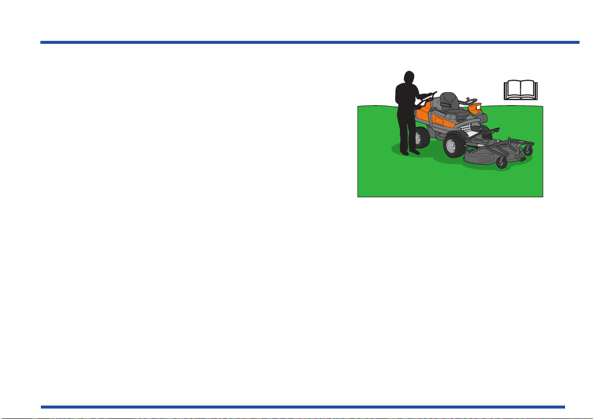
Read the operator’s manual before starting the machine
Safety Instructions
Chapter 3: Safety Instructions
These instructions are for your safety. Read them
carefully.
General Use
• Read all instructions in this operator’s manual and
on the machine before starting it. Ensure you
understand them and then observe them.
• Learn how to use the machine and its controls
safely and learn how to stop quickly. Also learn to
recognise the safety decals.
• If you get into a situation where you feel unsure
about how to progress, stop and seek expert
advice. Contact your Husqvarna retailer, service
agent or an experienced user. Avoid all usage that
you consider to be beyond your capability.
• Only allow the machine to be used by adults who
are familiar with its use.
• Make sure nobody else is in the vicinity of the
machine when you start the engine, engage the
drive, or run the machine.
Page 13
Safety Instructions
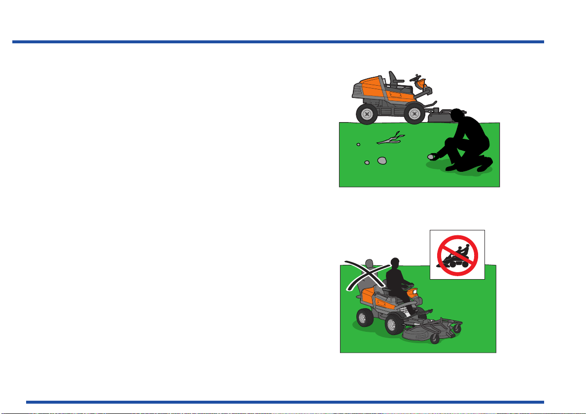
• Clear the area of objects such as stones, toys,
steel wire, etc. that may become caught in the
blades and thrown out.
• Beware of the rear ejector and do not point it at
any one.
• Stop the engine and prevent it from starting before
you clean the cutting unit.
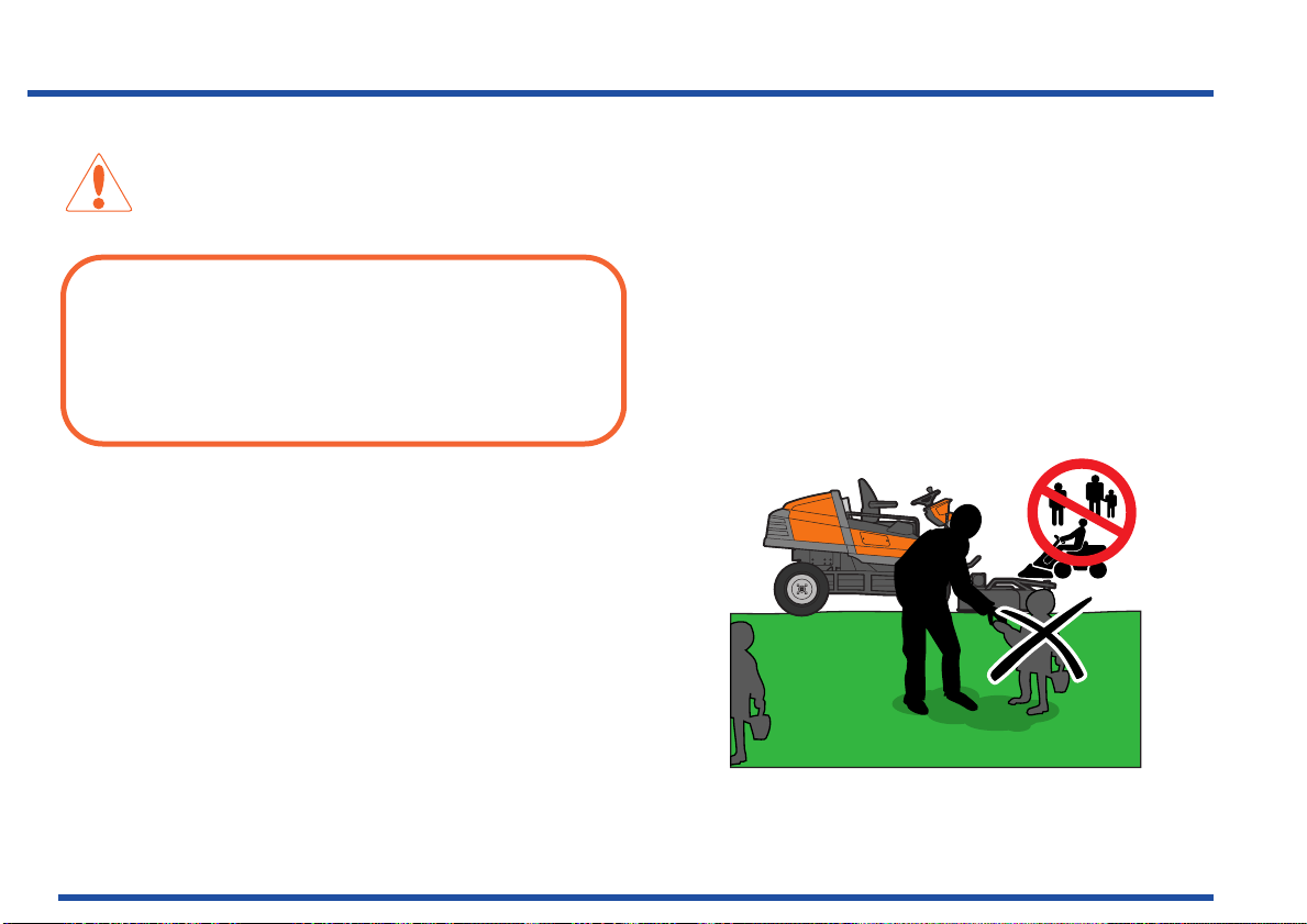
• Remember that the driver is responsible for
dangers or accidents.
• Never carry passengers. The machine is only
intended to be used by one person.
• Always look down and behind before and during
reversing manoeuvres. Keep watch for both large
and small obstacles.
• Slow down before turning.
12
Clear the area of objects before mowing
Never take passengers
Page 14
13
Shut down the blades
• Shut down the blades when not mowing. The
blades must only be running when the cutting unit
is lowered and active when used for mowing.
• Be careful when rounding fixed objects, so that the
blades do not hit them. Never run the machine
over foreign objects.
• Never drive close to objects or other machines.
Remember that “Brake pedal reflex” from driving a
car has the opposite effect if you press on the
forward pedal.
Safety Instructions
Page 15
Safety Instructions
WARNING:
Engine exhaust, some of its constituents and certain
vehicle components contain or emit chemicals
considered to cause cancer, birth defects or other
reproductive impairment. The engine emits carbon
monoxide, which is a colourless, poisonous gas. Do
not use the machine in enclosed spaces.
• Only use the machine in daylight or in other well-lit
conditions. Keep the machine at a safe distance
from holes or other irregularities in the ground. Pay
attention to other possible risks.
• Never use the machine if you are tired, if you have
consumed alcohol, or if you are taking other drugs
or medication that can affect your vision,
judgement, or co-ordination.
• Beware of traffic when working near or crossing a
road.
14
Keep children away from the work area
Page 16
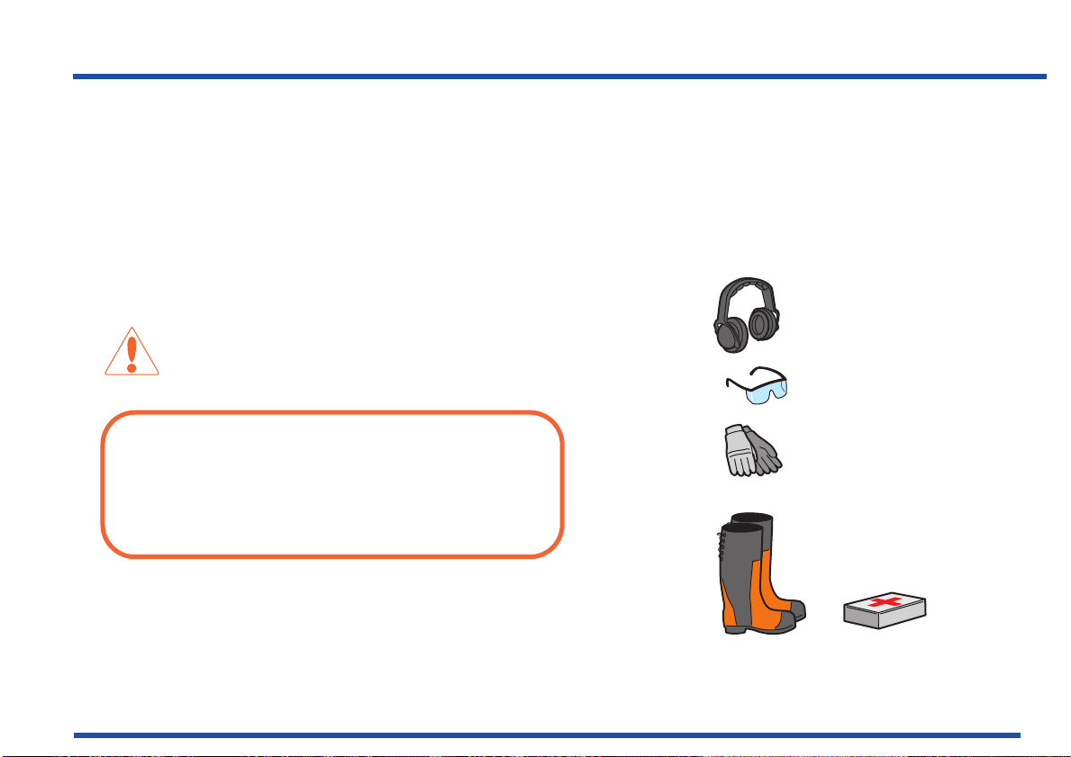
• Never leave the machine unsupervised with the
Personal protective equipment
motor running. Always stop the blades, apply the
parking brake, stop the engine and remove the
keys before leaving the machine.
• Never allow children or other persons not trained
in the use of the machine to use or service it. Local
laws may regulate the age of the user.
WARNING:
You must use approved personal protective
equipment whenever you use the machine. Personal
protective equipment cannot eliminate the risk of
injury but it will reduce the degree of injury if an
accident does happen. Ask your dealer for help in
choosing the right equipment.
15
Safety Instructions
• Use hearing protection to minimise the risk of
hearing impairment.
• Wear approved protective goggles or a full visor
when driving.
Page 17
Safety Instructions
• Never use the machine when barefoot. Always
wear protective shoes or protective boots,
preferably with steel toes.
• Make sure that you have first aid equipment close
at hand when using the machine.
Driving on slopes
Driving on slopes is one of the operations where the
risk of the driver losing control of the machine or of it
overturning is the greatest; this can result in serious
injury or death. All slopes demand extra care. If you
cannot reverse up a slope or if you feel unsure, do not
mow it.
16
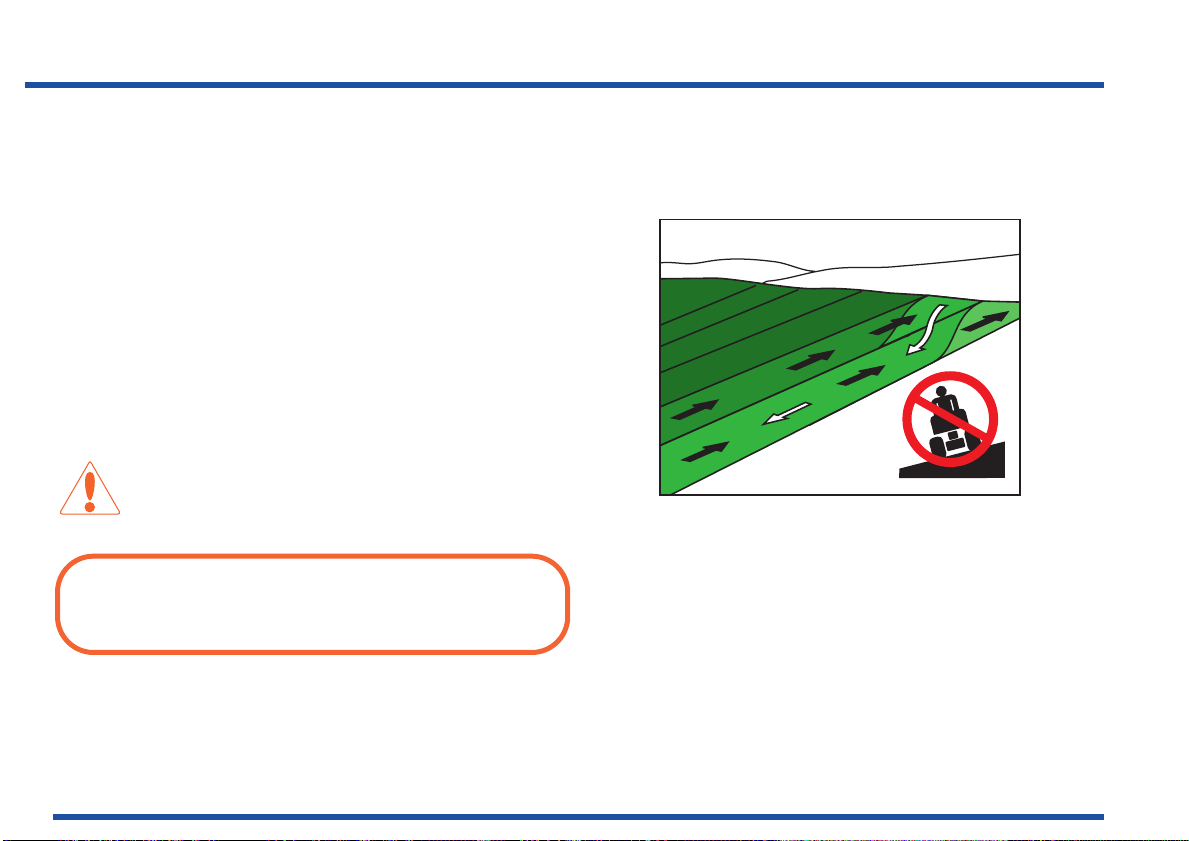
WARNING:
Do not drive down slopes with the unit raised.
Control can be reduced due to the changed centre of
gravity.
Do as follows
• Remove obstacles such as stones, tree branches, etc.
• Mow up and down, not side-to-side.
Mow upwards and downwards on slopes, not sideways.
Page 18
• The differential lock should also be used on
Be extra cautious when driving on slopes
slopes.
• Never drive the machine on terrain that slopes
more than 10°.
• Avoid starting or stopping on a slope. If the tyres
start to slip, stop the blades and drive slowly down
the slope.
• Always drive evenly and slowly on slopes.
• Make no sudden changes in speed or direction.
• Avoid unnecessary turns on slopes, and if it proves
necessary, turn slowly and gradually downward, if
possible.
• Watch out for and avoid driving over furrows,
holes, and bumps. It is easier for the machine to
overturn on uneven ground. Tall grass can hide
obstacles.
• Drive slowly. Do not turn the wheel sharply.
• Be extra cautious with any additional equipment,
which can alter the machine’s stability.
• Do not mow near verges, ditches, or banks. The
machine can suddenly overturn if one wheel
comes over the edge of a steep slope or a ditch, or
if an edge gives way.
• Do not mow wet grass. It is slippery, and tyres can
lose their grip so that the machine skids.
17
Safety Instructions
Page 19
Safety Instructions
• Try not to stabilise the machine by putting a foot on
the ground.
• When cleaning under the machine, it may never be
driven near verges or ditches.
Children
• Serious accidents may occur if you fail to be on
guard for children in the vicinity of the machine.
Children are often attracted to the machine and
mowing. Never assume that children will stay put
where you last saw them.
• Keep children away from the mowing area and
under close supervision by another adult.
• Keep an eye out and shut off the machine if
children enter the work area.
• Before and during a reversing manoeuvre, look
backward and downward for small children.
• Never allow a child to ride with you. They can fall
off and seriously injure themselves or be in the
way for safe manoeuvring of the machine.
• Never allow children to operate the machine.
• Be particularly careful near corners, bushes, trees
or other objects that block your view.
18
Never allow children to operate the machine
Page 20
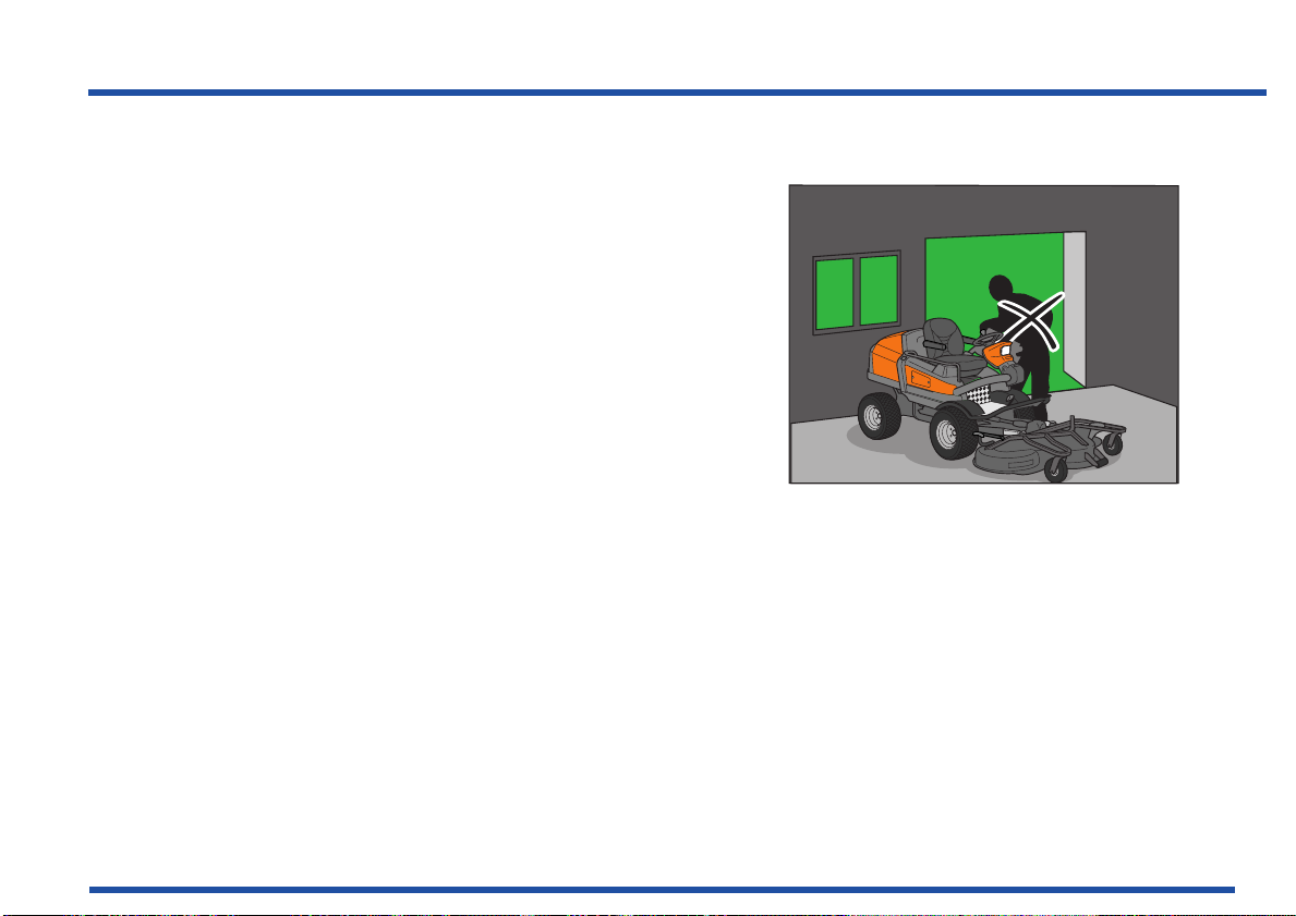
Maintenance
Never fill the fuel tank indoors
• Stop the engine. Remove the ignition key before
making any adjustments or carrying out
maintenance.
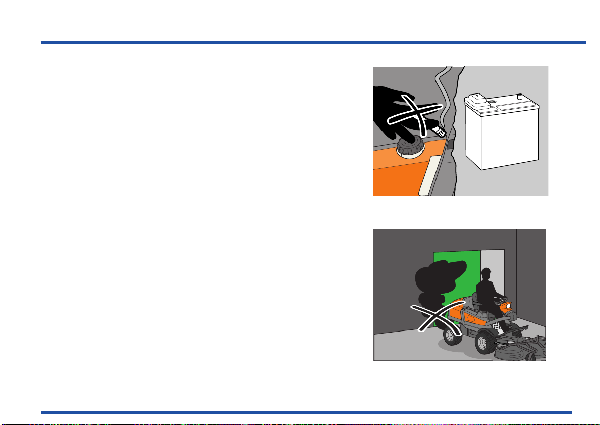
• Never fill the fuel tank indoors.
• Only store fuel in clean containers approved for
the purpose.
• Never remove the fuel cap or fill the fuel tank with
fuel while the engine is running.
• Allow the engine to cool before refuelling. Do not
smoke.
• Handle oil, oil filters, fuel and the battery carefully,
of environmental considerations. Observe
applicable recycling regulations.
• Do not allow compressed air to come into contact
with skin. If compressed air penetrates the skin,
seek medical advice immediately.
• Seek medical advice immediately if skin comes into
contact with fuel, which that is under high pressure.
• The combustible material in some of the engine’s
components (e.g. certain seals) can be very
dangerous if ignited. Never allow burnt material to
come into contact with skin or eyes.
19
Safety Instructions
Page 21
Safety Instructions
• Do not remove the filler cap or any other
component on the cooling system when the engine
is hot or under pressure, as hazardous hot coolant
can spray out.
WARNING:
The engine, exhaust system, cooling system and
hydraulic system components become extremely hot
during operation. Risk of burn injuries if touched.
Wear protective gloves
• If leaks arise in the fuel system, the engine must
not be started until the problem has been resolved.
• Store the machine and fuel in such a way that
there is no risk of leaking fuel or fuel vapour
leading to damages.
20
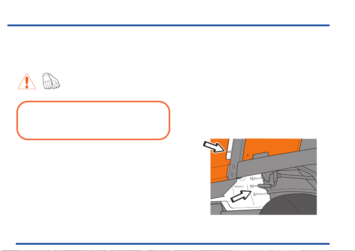
• Check the fuel level before each use and leave
space for the fuel to expand, because the heat
from the engine and the sun may otherwise cause
the fuel to expand and overflow.
Tank with level window
Page 22
• Avoid overfilling. In the event of spilling fuel on the
Risk of sparking
machine, wipe it up before starting the engine. If you
spill petrol on your clothing, change your clothing.
• Material that has been contaminated by fuel must be
moved to a fire proof and environmentally safe place.
• Allow the machine to cool before taking any
actions in the engine room.
WARNING:
The battery contains lead and lead compounds,
chemicals that are considered to cause cancer, birth
defects, and other reproductive system damage.
Wash you hands after touching the battery. Use
protective goggles when working with the battery.
21
Safety Instructions
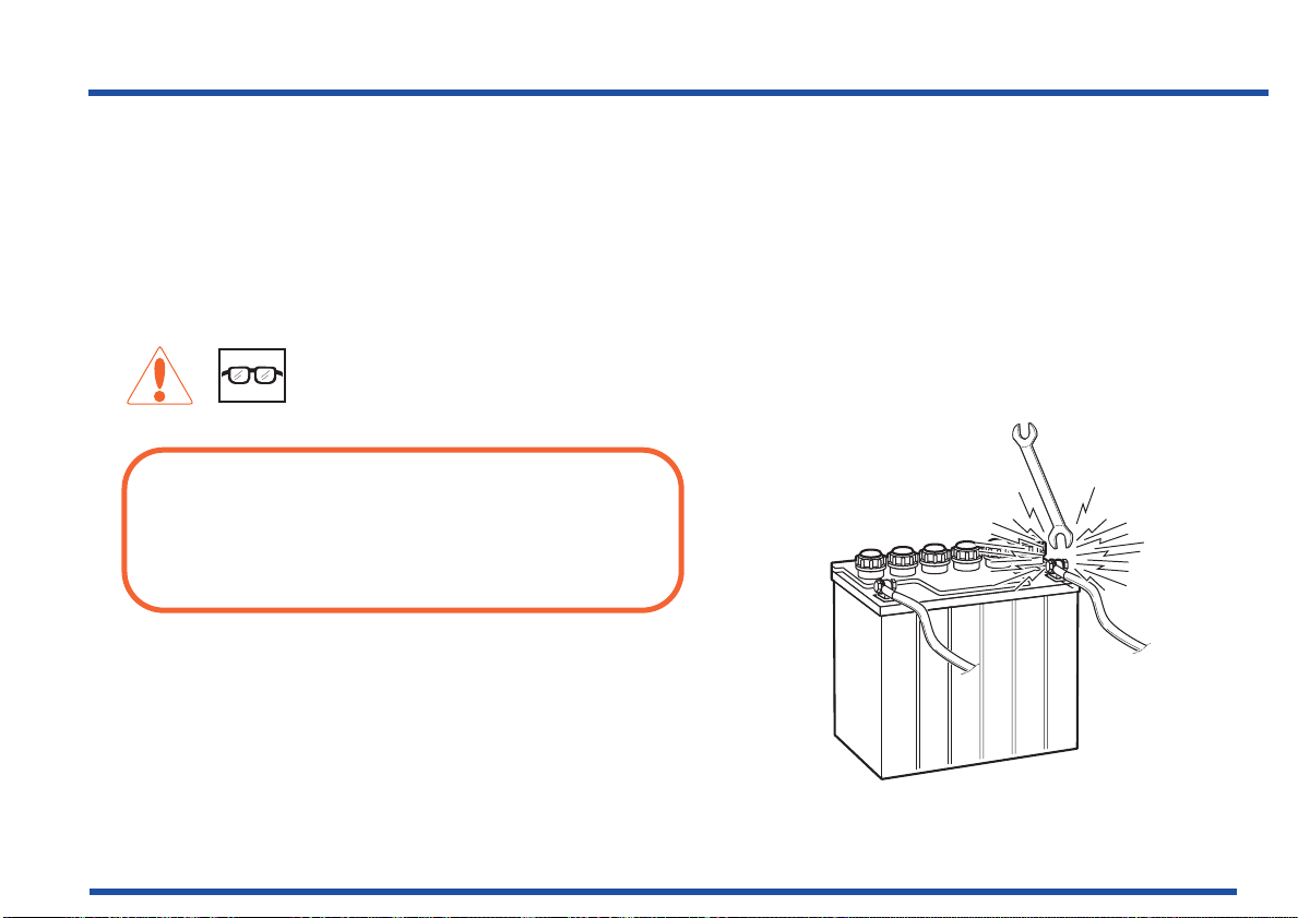
• Sparking can occur when working with the battery
and the thick cables in the starter motor circuit.
This can cause the battery to explode, fire or eye
injuries.
Sparking in the circuit can not occur once the
battery's power connection cable (usually the
black negative cable) has been disconnected.
Page 23

Safety Instructions
IMPORTANT INFORMATION:
Avoid sparking and its consequences by:
Wearing protective glasses.
Make sure that the fuel cap is fitted and that no
flammable liquids are stored in an open container.
Do not work on the starter motor circuit in the vicinity of
spilt fuel.
Disconnect the battery's power connection cable (usually
the black negative cable) first and connect it last.
Exercise care with tools so that short circuiting does
not occur.
Do not short circuit across the starter relay's
connections to run the starter motor.
• Be especially careful when handling battery acid.
Acid on the skin can cause serious corrosive
injuries. In the event of spillage on the skin wash
immediately with water.
22
Page 24
• Acid in the eyes can cause blindness, contact a
Do not smoke when carrying out maintenance
Never drive the machine in an enclosed space
doctor immediately.
• Be careful when servicing the battery. Explosive
gases form in the battery. Never perform
maintenance on the battery while smoking or in the
vicinity of open flames or sparks. This can cause
the battery to explode and cause serious injuries.
• Make sure all nuts and bolts are tightened correctly
and that the equipment is in good condition.
• Do not modify safety equipment. Check regularly to be
sure it works properly. The machine must not be driven
if protective plates, protective covers, safety switches or
other protective devices are not fitted or are defective.
• Do not change the settings of governors and avoid
running the engine with overly high engine speeds. If
you run too fast, you risk damaging the machine
components.
• Never use the machine indoors or in spaces lacking
proper ventilation. Exhaust fumes contain carbon
monoxide, an odourless, poisonous and highly
dangerous gas.
• Stop and inspect the equipment if you run over or into
anything. If necessary, make repairs before starting.
• Never make adjustments with the engine running.
23
Safety Instructions
Page 25
Safety Instructions
• The machine is tested and approved only with the
equipment originally provided or recommended by the
manufacturer.
• The blades are sharp and can cause cuts and gashes.
Wrap the blades or wear protective gloves when
handling them.
• Check the parking brake’s functionality regularly.
Adjust and maintain as required.
• The mulching unit should only be used where better
quality mowing is required and in known areas.
• Reduce the risk of fire by removing grass, leaves
and other debris that may have fastened in the
machine. Allow the machine to cool before putting
it in storage.
• Do not turn over the engine by hand without
preventing the engine from starting, which can be
done in different ways:
a. Remove the glow plug, no compression the engine
can therefore be easily turned over.
24
b. Loosen a pressure pipe connection on each jet
pipe a 1/2 turn.
c. Secure the injection pump stop arm in position for
zero supply.
Clean the machine regularly
Page 26
25
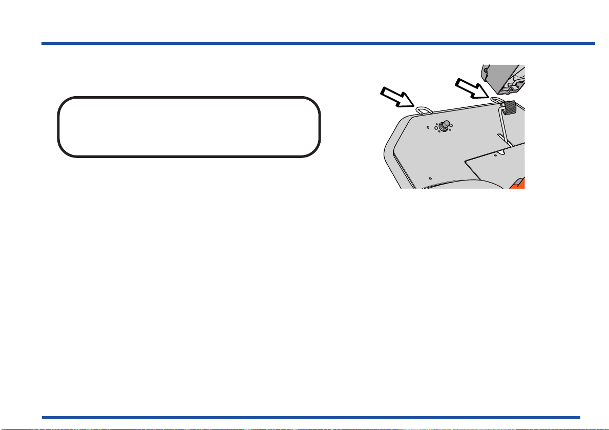
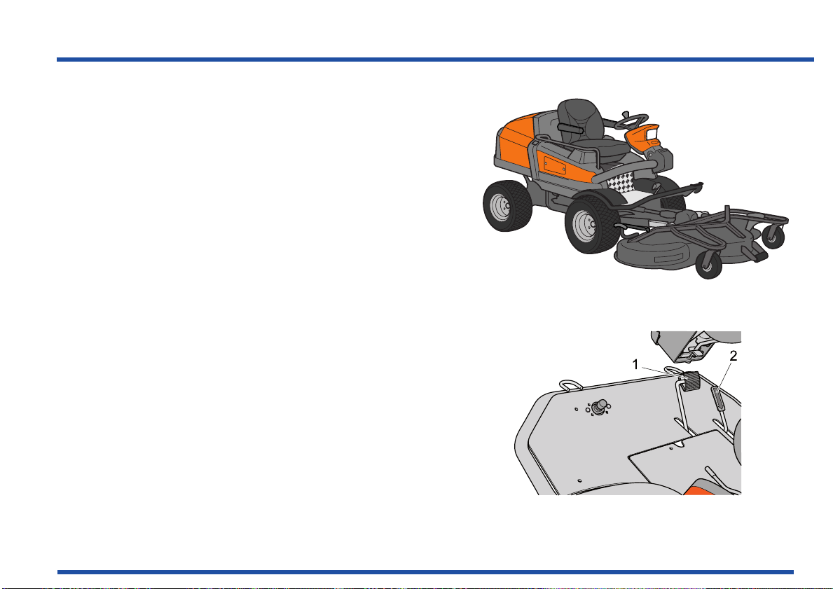
Front securing eyelets
Safety Instructions
Transport
IMPORTANT INFORMATION:
The parking brake is not sufficient to lock the
machine during transport. Ensure you secure the
machine firmly to the transporting vehicle.
The machine is heavy and can cause serious crushing
injuries. Be extra cautious when it is loaded on or
unloaded from a vehicle or trailer.
• Use an approved trailer to transport the machine.
Activate the parking brake and secure the machine
using approved fasteners, such as straps, chains
or ropes when transporting.
• Check and comply with laws and regulations when
driving on public roads, a traffic kit is available as
an option. This can be retrofitted on PT 26D.
Page 27

Safety Instructions
Environment protection
Take care of the environment, there are numerous
environmental risks especially when performing
maintenance on the machine. This particularly applies
when dealing with engine oil, hydraulic oil, fuel, oil
filters, hydraulic filters and fuel filters. You must be
attentive to ensure spillage does not occur when you
open a system that contains oil or fuel.
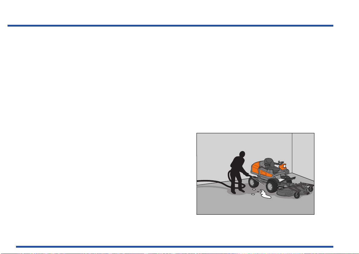
• Always wipe up spillage. When using cloths,
sawdust or oil absorbents, these should be treated
as environmental hazardous waste. Follow local
regulations.
• Choose an area, preferably with a concrete floor,
when you handle or store oils and fuel so that you
can clear up any spillage without it penetrating into
the ground.
• Avoid spillage, use a funnel and fill carefully.
• When draining, ensure that a suitably sized
container is placed correctly. Remember that the
oil does not always run straight down.
• Transfer the waste oil into a sealed container and
hand in for destruction. Remember to follow local
regulations. Generally you can deposit waste oil at
workshops or petrol stations that handle waste oil.
26
Page 28

• Replaced oil and fuel filters are environmental
hazardous waste, handle them as waste oil.
• Do not spill fuel when refuelling. One litre of diesel
fuel can, according to the Swedish Rescue
Services Agency, destroy up to one million litres of
drinking water. Spilt fuel is a fire risk.
• Wash your hands thoroughly when the job is done.
• Coolant is poisonous and sweet. Ensure that
animals do not come into contact with open
containers or pools of fluid.
• Bear in mind the risk of grass fire when working in
dry vegetation. Never operate a machine with a
modified or damaged muffler, as sparks from the
exhaust fumes can set dry grass on fire.
27
Safety Instructions
Page 29

Safety Instructions
User responsibility
• Study and follow the safety instructions, see
“Safety Instructions” on page 11.
• Follow the maintenance schedule for care, see
“Maintenance Schedule” on page 71, lubrication
chart, see “Lubrication Schedule” on page 111 and
the instructions for operating the machine, see
“Presentation” on page 29 and “Driving” on
page 57.
• Follow the maintenance instructions, see
“Maintenance” on page 71, lubrication, see
“Lubrication” on page 111 and storage, see
“Storage” on page 133.
28
Page 30
29
PT 26D
Speed control
Presentation
Chapter 4: Presentation
Congratulations on your choice of an exceptionally
high quality product. This operator's manual describes
Husqvarna PT 26D.
It is fitted with a Perkins 3 cylinder diesel engine
developing 26 horse power.
PT 26D is equipped with hydraulic steering and
attachment lift. They are supplied with pressure from a
pump on the engine.
The machine is all wheel drive in low speed mode.
The power transmission from the engine is hydrostatic.
It is supplied with pressure by a pump under the
driver’s seat. A shaft with two flexible couplings
powers the pump. Flow and direction are regulated
with the pedals, so that forward and reversing speeds
are variably controlled. One pedal to drive forwards (1)
and one pedal to reverse (2). The pump drives four
hydraulic motors in parallel, one for each wheel.
The power transmission is also used as service brake.
There are low and high speeds for driving. High or low
speed is selected using a switch.
Page 31

Presentation
The machine is equipped with an electro-hydraulic
differential lock, which is controlled by a pedal. The
differential lock only works longitudinally, which means
that you can turn the machine with the differential lock
activated.
The differential lock does not work in high speed.
Rear light, horn, direction indicators and rotating
warning lights are optional equipment (traffic kit).
The cutting unit takes power from the engine by means
of an electromagnetic clutch, two V-belts, apower takeoff shaft, a propeller shaft and a bevel gear.
Differential lock pedal
30
Page 32

1. Speed control for driving forwards page 34
2. Speed control for reversing page 34
3. Parking brake page 35
4. Control panel page 32
5. Knob for the backrest rake page 36
6. Catch for seat folding page 35
7. Knob for the lumbar support page 37
8. Lever for lateral seat adjustment page 36
9. Knob for seat suspension page 36
10. Steering wheel console page 33
11. Pedal for differential lock page 38
12. Cranks for setting cutting height page 38
13. Fuel tank cover page 39
Placement of controls
31
Presentation
Page 33

Presentation
32
Control panel
21. Control lever hydraulics page 40
22. Switch for operating the cutting unit page 42
23. Switch for 2nd hydraulic function (option) page 42
24. Horn switch (option) page 43
25. Turn signal lights switch (option) page 43
26. Starter switch page 44
27. Switch for the lights page 44
28. Throttle control page 45
29. Switch for high and low speed page 45
-
30. Switch for weight transfer page 46
31. Rotating warning light (option) page 46
32. Parking lights (option) page 47
33. Spare
34. Power outlet page 47
35. Mains switch power outlet page 47
36. Chronometer page 48
Page 34

Presentation
40. Warning lamp Battery charging page 48
41. Warning lamp Differential lock page 48
42. Warning lamp Coolant temperature page 48
43. Warning lamp Glow plug heating page 48
44. Warning lamp Engine oil pressure page 48
45. Warning lamp Cutting unit operation page 48
46. Warning lamp Parking brake page 48
47. Warning lamp High speed page 48
48. Warning lamp Right-hand indicator page 48
49. Lever for tilting the steering wheel console page 49
50. Warning lamp Full beam page 48
51. Warning lamp Left-hand indicator page 48
Steering wheel console
33
Page 35

Presentation
1-2. Speed control
The speed of the machine is variably controlled using
two pedals. Pedal (1) is used to travel forwards and
pedal (2) to reverse.
WARNING:
Make sure that no branches can interfere with the
pedals when mowing under bushes.
Speed control
34
Page 36

3. Parking brake
Parking brake
Seat lock
6
Apply the parking brake by moving the handle forward.
Release the parking brake by moving the handle back.
4. Control panel
There are controls and switches on the control panel
on the right-hand side of the driver that are used when
operating the machine. The lower section of the panel
is equipped with a cover over the machine’s fuses and
relays. See “21-37. Controls on the control panel” on
page 40.
5-9. Seat
The seat has a hinged mounting on the front edge and
can be folded forwards.
To fold the seat forward, the steering wheel console
must be folded forwards and the lock (6) for the seat
operated.
Presentation
35
Page 37

Presentation
WARNING:
Do not adjust the seat whilst driving. Risk of unsafe
operation.
The seat can also be adjusted lengthways:
• When making adjustments, the lever (8) under the
left-hand side of the seat is moved to the left, after
which the seat can be moved backwards or
forwards to the desired position.
• The seat’s suspension can be adjusted by turning
the knob (9) under the front edge of the seat. A
scale indicates the setting.
There are two knobs on the sides of the backrest:
Lateral adjustment and adjusting suspension
• Backrest tilt is adjusted using the knob (5) on the
right-hand side of the seat.
36
djusting the backrest tilt
Page 38

• Lumbar support is adjusted using a knob (7) on the
Steering wheel and steering wheel console
left-hand side of the backrest.
Presentation
10. Steering wheel and steering wheel console
The position of the steering wheel can be adjusted
vertically. The mounting for the steering unit in the
steering column can be adjusted vertically.
Depress the lever (49) and fold the steering wheel
console to one side to facilitate entering the driver’s
seat. The steering wheel console can be adjusted
lengthways.
See “40-51. Warning lamps” on page 48.
The headlights are set using the knob in the position
closest to the driver. In the second position the range
of the lighting will decrease.
Knob for the lumbar support
49
37
Page 39

Presentation
11. Differential Lock
The differential lock is electro-hydraulic. It is operated
by a pedal controlled switch. The differential lock only
works longitudinally, it ensures operation on at least
one front wheel and one rear wheel. This means that
you can turn the machine with engaged differential
lock without causing any interruptions in the power
transmission or damage to the lawn.
As the differential lock is not mechanical, it can be
engaged or disengaged without limitation, even when the
machine freewheels or in the event of wheel spin. When
the pedal is released, the differential lock disengages
without the driver having to carry out any other
operations. The differential lock only works at low speed
and is active both up and down slopes.
12. Adjusting the cutting height
The cutting height adjustment allows the cutting height
to be adjusted in seven different positions 25.4 mm 127 mm (1” - 5”).
In order to obtain an even cutting height, it is important
that the settings are in the same positions and the air
pressure is the same in the front wheels, 100 kPa /
1.0 bar / 14.5 PSI and in the cutting unit’s pivot wheels
150 kPa / 1.5 bar / 21,7 PSI
When the adjustments have been made, the cranks
should be released using the button in the crank and set
to a position that does not catch on any bushes or similar.
Differential lock pedal
Front cutting height adjustment
38
Page 40

Presentation
Tank with level window
13. Fuelling
The fuel level in the tank is indicated in the sight glass.
Do not fill the tank completely, leave an area of at least 2.5 cm (1").
Fill the fuel tank with diesel. Do not use petrol under
any circumstances.
Use fuel with a cetane rating of above 45. Max RME
mixture 5 % in mineral oil based fuels. Aviation kerosene
(JP5, JP8 and Jet-A) can be used if lubricant additives
are used, but the starting ability may be affected. JP4 is
not recommended. Unmixed RME can be used.
Do not smoke when filling the tank with fuel.
Diesel is less flammable than petrol at normal temperatures, but becomes very flammable if heated to the flash
point. This varies depending on the type of diesel but is normally higher than +50 °C (120 °F).
Observe fuel hygiene. The diesel engine’s fuel injection system is very sensitive and can be damaged by
contaminants, which may be so small that they cannot be seen with the naked eye. Only use clean containers
(closed + dust-free funnel). Wipe away any dust before removing the fuel tank filler cap. There is a filter to protect
the fuel injection system, however if it becomes blocked operational malfunctions may occur. Rectifying damage,
operational malfunctions, filter replacement caused by poor hygiene are not repairs that are covered under warranty
Remember the environmental risks. See “Environment protection” on page 26.
Wipe up any spillages. Material that has been contaminated by fuel must be moved to a safe place.
If you spill fuel on your clothes, change to prevent skin irritations.
39
Page 41

Presentation
Winter fuel and paraffin precipitation
Malfunctioning can occur when driving in extremely
cold conditions on account of paraffin precipitation,
which can occur if using standard fuel. To avoid this,
winter fuel, diesel with additives to prevent precipitation,
is sold in relevant climates. In certain regions different
types of summer and winter fuels are sold, in other
regions. winter fuel is sold all year round. Ask you fuel
supplier and only use winter fuel below 0 °C (+32 °F).
21-37. Controls on the control panel
The control panel is prepared for optional extras,
which are sold as accessories for PT 26D. Therefore,
some of the following control units may not be included
with your machine.
21. Control lever hydraulics
The lifting lever is used to put the cutting unit in either
the transport or mowing position when hydraulic
pressure is available.
Lifting the cutting unit (transport position)
Stop the blades by pressing in the switch for driving
the cutting unit (22).
40
Raising the cutting unit with the lifting lever
Page 42

Pull the lever backward to engage the transport position.
Mowing Position
The unit is then raised.
The cutting unit can be raised slightly with the blades
in operation. This is to facilitate work when cutting in
extremely tall grass or on uneven surfaces. The
machine is, however, equipped with an automatic
blade stop function, which is activated when the
cutting unit reaches the transport position. If the
automatic blade stop is activated, the switch (22) must
be pressed in and pulled out to restart.
Lowering the unit (mowing position)
Move the lifting lever forwards to engage the cutting
position. The unit is then lowered. The lever does not
need to be held in position, allow it to spring back to
the zero position when the unit has been lowered.
The blades are started with the switch for driving the
cutting unit (22).
Weight transfer can be activated, which means the cutting
unit follows the ground contour and unevenness on the
lawn more precisely. See “Weight transfer” page 46
Presentation
Other functions (option)
When the lever is moved laterally, the oil pressure is
operated to the 2nd hydraulic function, the terminals
are under the foot plate hatch.
41
Page 43

Presentation
22. Switch for operation of cutting unit
The cutting unit can only be started when the driver is sitting in the seat.
• Pull out the switch to engage cutting unit
operation.
• Press in the switch to disengage cutting unit
operation.
If the safety circuit trips cutting unit operation, the
switch must be pressed in and pulled out again.
The safety circuit trips and the cutting unit stops:
When the cutting unit is raised to the uppermost
position
When the driver leaves the seat. There is a brief delay to
prevent stoppages should the driver bounce in the seat
When high gear is engaged.
When the starter is activated.
23. Switch for extra hydraulic function
(hydraulic kit option)
The switch is used, among others, when steering the
folding plough for individual control of the left or righthand plough-blades. Operate the plough blade using
the lever (21).
Switch for operation of cutting unit
Switch for extra 12 V outlet
42
Page 44

24. Push button for horn (traffic kit option)
25. Indicators (traffic kit option)
Press for the left-hand or right-hand indicator. Blinkers
are switched off automatically after approximately
30 seconds or manually by pressing in the same
direction. A new 30 second period is activated if you
press after the blinkers have been switched off.
Pressing in the opposite direction while flashing,
activates the blinkers for the opposite side for
30 seconds.
Presentation
Switch for horn
Switch for indicators
43
Page 45

Presentation
26. Starter switch
Three positions:
• OFF
All functions switched off. The engine is stopped. The
parking light can be switched on (traffic kit option).
•ON
Normal operating position.
• Start and Preheating
Keep the switch in the glow plug mode, when glow
plug heating is complete the starter is engaged.
During glow plug heating, light (43) on the indicator
panel comes on. Non-locking to position ON.
Turning again within 2 seconds gives starting
without glow plug heating.
27. Headlight
Three positions, clockwise in the following order:
• Off:
• Dipped beam
• Full beam
If the switch is moved to the Dipped beam position
automatic dipped beam mode, dipped beam is
switched on when the engine is running.
Starter switch
Switch for headlight
44
Page 46

28. Throttle control
Throttle control
High speed
The accelerator is used to control the speed of the
engine and thereby also the rotation speed of the blades.
In order to increase or decrease the engine speed, the
control is moved forwards or backwards respectively.
29. High speed
Activated switch. This switch is used to select either
high or low speed.
The speed must drop to zero before the machine shifts
to low speed if high speed is actuated.
If the differential lock is actuated, the machine will not
shift to high speed until the pedal is released.
Front wheel drive is engaged in high speed mode.
Presentation
All wheel drive is engaged in low speed mode.
The differential lock and cutting unit only work in low
speed mode.
45
Page 47

Presentation
30. Weight transfer
Weight transfer is activated using this switch, transfers
a proportion of the unit’s weight to the machine. This
causes greater ground pressure on the machine’s
front wheels and lower ground pressure on the unit’s
pivot wheels.
It is recommended to use weight transfer when lawn
mowing and sweeping. When snow clearing or
changing tools, the function should be off so that the
lifting arms can be lowered.
This function works when the lower position is
selected with control lever (21).
31. Rotating warning light (traffic kit option)
Observe any local traffic laws when using the warning
light.
Weight transfer
46
Rotating warning light
Page 48

32. Parking lights (traffic kit option)
Parking lights
Power outlet with switch
Can be lit using the switch even if the ignition switch is
not switched on. The battery will be completely
drained in approximately 20 hours.
The parking light is lit automatically when the engine is
running, even if the switch is not switched on.
33. Spare
34-35.Power outlet
A seat heater or mobile phone charger are examples
of articles that can be connected to the power socket (34).
The power outlet is switched on and off using power
switch (35) on the control panel.
The electrical outlet socket is fuse protected by its own
fuse FU11 (max. 10 A), which is located behind a
cover on the outside of the control panel.
Presentation
47
Page 49

Presentation
36. Chronometer
The chronometer shows how many hours the engine
has been running. Any time when the engine is not
running but the ignition is switched on is not registered.
The last digit shows tenths of an hour (6 minutes).
40-51. Warning lamps
On the steering wheel console under the steering wheel
there are warning lamps for battery charging (40),
differential lock (41), coolant temperature (42), glow
plug heating (43), oil pressure (44), cutting unit
operation (45), parking brake (46), high speed (47), full
beam (50) and indicators (48, 51).
During start-up all lights come on for function checks.
The most important lights are coolant temperature and
oil pressure. The engine stops automatically if any of
these light up.
The lamp for the coolant temperature flashes at
approximately 100oC and lights constantly at
approximately 110oC when the engine stops.
Reduce the load to lower the temperature if the lamp
flashes.
The warning lamps are LEDs, which cannot be
replaced separately. The entire indication panel must
be replaced in the event of a fault.
Chronometer
Warning lamps
48
Page 50

49. Lever for steering wheel console angle
When the lever is activated, the angle of the steering
wheel console can be adjusted for a more comfortable
driving position or to facilitate entering the driver’s
seat. The lever is sprung.
Presentation
49
WARNING:
Do not adjust the steering wheel angle or whilst
driving. Risk of unsafe operation.
Adjusting the steering wheel setting
The mounting for the steering unit in the steering
column can be adjusted vertically. Undo the screws
that hold the casing and remove the screws, on both
sides of the column, that hold the mounting in the
column. Adjust the mounting to the correct height,
screw the mounting into place in the column and fit the
casing.
Adjusting the steering wheel console angle and steering
wheel
Adjusting the steering column vertically.
49
Page 51

Presentation
Cooling system
IMPORTANT INFORMATION:
Coolant must be a mixture of 50 % antifreeze fluid
and 50 % soft water. Anticorrosion agent in the
coolant will be diluted if a reduced mixture is used.
A higher mixture can negatively influence the cooling
capacity. Salt water or water with a high lime content
can cause corrosion or deposits in the cooling system.
The engine is water cooled. In the event of a high engine coolant temperature being indicated, check the coolant
level first.
Also check that the radiator grille behind the driver's seat is not clogged. See “Checking radiatorgrilles” on page 79.
The correct engine coolant level is important for the cooling system to function properly. Therefore, the engine
coolant level should be checked regularly. See warnings on the next page. The coolant must be visible when the
filler cap is removed.
Continuous coolant losses mean that there is a leak. In such a case, the cooling system should be checked by a
qualified technician. It is not sufficient to only top up the coolant. If the engine overheats, the coolant drops. Allow the
engine to cool before filling.
Coolant filling
The cooling system must not be filled with salt water, this causes corrosion damage to the engine.
Change the coolant if it is discoloured or dirty. The cooling system must then be thoroughly flushed.
50
Page 52

WARNING:
Coolant draining engine block
Coolant draining lower hose
Do not open the cap quickly when the engine is hot,
first release the overpressure with the cap partially
slackened off. Risk of burns. Use protective gloves
and protective goggles.
WARNING:
The antifreeze fluid and coolant are hazardous to
health. Store them in marked containers that are
inaccessible to children and animals.
Presentation
When draining the cooling system, both the taps must
be opened.
51
Page 53

Presentation
IMPORTANT INFORMATION:
Never fill a hot engine with cold coolant. Risk of
extensive engine damage.
Only fill antifreeze and water ready mixed in a 50/50 ratio.
Check the level when the engine has been driven for a few minutes after filling. There could have been air in the
system which has now been released.
Antifreeze
Only use a glycol based antifreeze that is approved by the applicable norms BS 6580:1992 or ASTMD 3306-89 or
AS 2108-1977 (indicated on the packaging).
The antifreeze agent must be intended for use with light alloy engines.
Your Husqvarna supplier can provide the correct type of antifreeze agent.
52
Page 54

IMPORTANT INFORMATION:
Mixing table
Glycol Water Freezing point
60 % 40 % - 47 °C
50 % 50 % - 37 °C
40 % 60 % - 25 °C
If you use the incorrect type or mix different types of
antifreeze agents, a chemical reaction may occur,
which causes overheating and severe engine damage.
These are not covered by the warranty.
Use antifreeze agent all year round and even in
climates that do not have a risk of frost. The antifreeze
agent contains additives that protect the engine
cooling system against corrosion.
Presentation
53
Page 55

Presentation
Cutting unit
PT 26D can be equipped with cutting unit, Combi 132
with a 132 cm cutting width or Combi 155 with a
155 cm cutting width.
The cutting unit is driven by a v-belt, a power take-off
shaft and a propeller shaft from the engine. It is
engaged by an electro magnetic clutch, which is
located in front of the engine’s flywheel.
The Combi unit functions as a BioClip unit when a
BioClip plug is fitted under the unit cover, but can be
set to rear ejection by removing the BioClip plug.
The unit’s BioClip function finely chops the grass
several times before returning it to the lawn as
fertiliser. The rear ejector ejects the clippings behind
the unit without finely chopping them.
Cutting unit Combi 155 can be mounted 8 cm (3 1/8")
laterally to the side in relation to the machine.
If necessary, the cutting unit can be turned to the
service position to be able to clean the underneath of
the cover for example.
Cutting unit Combi 155
54
Service position
Page 56

Accessories
Unscrew the bypass valve when towing
The accessories are described in separate operator’s
manuals. Contact your dealer if you require an
accessory.
Examples of original accessories available for
Husqvarna PT 26D:
• Traffic kit: Lighting with direction indicators, parking
light and rotating warning lamp
• Accessory hydraulic kit; Hydraulic valves, quick
couplings,hydraulic hoses, switch and cable
harness
• Brush
• V blade
• ROPS
• Bucket with hydraulic emptying
• Catalytic converter.
Towing
Towing must be avoided. Only damaged machines that
cannot be driven may be towed in the event of being
recovered or loaded onto vehicles.
The bypass valve must be loosened by 2-4 turns when
towing. Lift the driver’s seat and unscrew the bypass
valve. Remember to retighten the valve.
Presentation
55
Page 57

Presentation
56
Page 58

Chapter 5: Driving
Mowing Tips
WARNING:
Use ear protection.
Clear the lawn of stones and other objects that can
be thrown out by the blades.
• Locate and mark plants, rocks and other fixed
objects in order to avoid collisions.
• Begin with a high cutting height and reduce it until
the desired mowing result is attained.
• The mowing result will be best with a high engine
speed (the blades rotate rapidly) and low speed
(the machine moves slowly). If the grass is not too
high and thick, the driving speed can be increased
without noticeably depreciating the mowing result.
Driving
Mark objects if necessary
57
Page 59

Driving
WARNING:
Never drive the machine on terrain that slopes more
than 10°. Mow upwards and downward on slopes,
never sideways. Avoid sudden directional changes.
• The finest lawns are obtained by mowing often.
Mowing will be more even and the clippings will be
more evenly distributed across the area. Mowing
time will not be longer as higher driving speeds
can be selected without impairing the mowing
result.
• Avoid cutting wet grass. The mowing result is often
worse as the grass clippings lump together more
easily and the ground is more easily damaged.
Max 10° in all directions
• Clean the underneath of the cutting unit after use.
When cleaning, the cutting unit should be moved
into the service position. If water is used, lower the
cutting unit and let the blades rotate a few minutes
to drive any water out of the bearings and belts.
58
Service position
Page 60

• It is important to mow frequently when mowing
Differential lock pedal
Air intake
with the mulching function.
• Use the differential lock if there is a risk of wheel
spin. The differential lock can be engaged during
operation and turns can be made with it engaged.
Before Starting
IMPORTANT INFORMATION:
The air intake grille behind the driver's seat must not
be blocked by, for example, clothing, leaves, grass or
dirt. Impaired cooling of the engine. Risk of major
engine damage.
IMPORTANT INFORMATION:
Start gas or ether must not be used for this engine.
Driving
• Read section “Safety Instructions” on page 11 and
“Presentation” on page 29.
59
Page 61

Driving
• Carry out daily maintenance according to
“Maintenance Schedule” on page 71.
• Adjust the seat to the desired position. See “5-9.
Seat” on page 35.
• Adjust the steering wheel and steering wheel
console to the desired position.
• See “10. Steering wheel and steering wheel
console” on page 37.
• Select the required cutting height (1-7) using the
cutting height settings. Move the knob to the
horizontal position so that it does not catch on
bushes or similar.
Cutting height setting
60
Cutting height settings
Page 62

Starting the engine
Apply the parking brake.
Engine speed control in max. speed position
1. Apply the parking brake by moving the handle
forward.
The engine cannot be started if the parking brake
is applied or if a driving pedal is pressed.
Check that the switch for the cutting unit drive is
depressed. If the engine starts with the switch
pulled out, it must be pushed in and pulled out
again in order for the cutting unit to work.
2. Move the speed control to the max speed position
so the injection pump is set to full feed mode.
Driving
61
Page 63

Driving
3. Turn the ignition key to the glow plug heating
position and keep it there until the warning light on
the steering wheel console goes out and the
starter motor engages. Glow plug heating is
dependent on the engine temperature. If you
require an extend glow plug heating period, you
must wait in the OFF or ON position for 4 seconds.
If the glow plug heating lamp does not come on
and the starter is not engaged, check that the
parking brake is engaged and that the drive pedals
are not actuated. Starting without glow plug
heating (warm engine) is possible if you turn the
ignition key to glow plug mode, back to ON and to
glow plug heating again within 2 seconds.
IMPORTANT INFORMATION:
Do not run the starter motor for more than
15 seconds at a time. If the engine does not start, wait
about 30 seconds before trying again.
Ignition key, glow plug heating and start position
4. When the engine starts, immediately release the
ignition key back to the intermediate position.
62
Starter key, intermediate position (ON)
Page 64

WARNING:
Engine speed control in idling mode
Start gas or ether must not be used
Never run the engine indoors, in enclosed or badly
ventilated areas. Engine exhaust fumes contain
poisonous carbon monoxide and carcinogenic
substances.
5. Set the desired engine speed (even idle) using the throttle
control.
Allow the engine to run at a moderate speed, for
3-5 minutes before loading it heavily.
Starting in cold conditions
If the engine does not start due to cold conditions,
repeat glow plug heating and try starting again.
Driving
Start gas or ether must not be used.
63
Page 65

Driving
Starting with a weak battery
WARNING:
Lead-acid batteries produce explosive gases. Avoid
sparks, open flames and smoking close to batteries.
Always wear protective glasses in the vicinity of
batteries.
If the battery is too weak to start the engine, it should
be recharged.
If jump leads are used for emergency starting, follow
the procedure below:
IMPORTANT INFORMATION:
64
Your Rider is equipped with a 12-volt system with
negative earth. The other vehicle must also have a 12volt system with negative earth. Do not use your lawn
mower battery to start other vehicles.
Page 66

Connecting jump leads:
Jump starting
• Connect each end of the RED lead to the
POSITIVE terminal (+) on each battery, and take
care not to short-circuit an end against the chassis.
• Connect one end of the BLACK lead to the
NEGATIVE terminal (-) on the battery that is fully
charged.
• Connect the other end of the BLACK lead to a
good CHASSIS EARTH, away from the fuel tank
and battery.
Remove the leads in reverse order:
• The BLACK cable is removed from the chassis
and then the fully charged battery.
• Finally the RED cable from both batteries.
Driving
65
Page 67

Driving
Driving the machine
1. Release the parking brake by pulling the handle
up.
2. Select high or low speed with the switch on the
control panel.
Parking brake
66
Speed selector
Page 68

3. Carefully press down one of the pedals until the
Driving pedals
Lifting lever lowering position
required speed is attained.
Pedal (1) is pressed down to travel forwards and
pedal (2) to reverse.
4. Lower the cutting unit to the ground using the
lifting lever. Move the lifting lever forwards.
Driving
67
Page 69

Driving
5. Activate weight transfer if desired using the switch (30)
on the control panel. The weight transfer position
must always be activated when driving up slopes
and deactivated when driving down slopes.
6. Start the cutting unit as necessary using the switch
for power take-off (22) on the control panel.
The cutting unit can only be started in low speed. If
the switch has already been pulled out and the unit
does not start, press it in and pull it out again
(See safety circuit on page 42).
Braking
Release the drive pedals. The machine slows and is stopped by
the drive system. Do not use the parking brake as the drive
brake.
Quicker braking is possible if you press down the drive pedal for
the opposite direction.
Switch for power take-off and weight transfer
68
Page 70

Cutting the engine
Switch off the cutting unit
Stop position
If the engine has been worked hard, it is preferable to
let the engine idle for a minute so it is running at its
normal working temperature when it is stopped.
1. Switch off the cutting unit if it is running.
2. Lift the cutting unit using the lifting lever.
3. Move the throttle control to the “MIN” position. Turn
the ignition key to “OFF”.
Driving
69
Page 71

Driving
4. Apply the parking brake, when the machine is
stationary, by first pulling up the lock handle (36)
on the control panel and then press down the
parking brake pedal (3).
Bleeding in the event of fuel stoppage.
See the chapter, Maintenance “Bleeding the fuel
system” on page 86.
Engine stop
If the engine stops, it is still possible to steer, but the
wheel is heavy to turn. As the transmission is
hydrostatic the machine stops immediately.
Parking brake
70
Page 72

Maintenance
500 1000 2000 3000250
Chapter 6: Maintenance
It is good practice to always check for leaks and loose components after use. Also check the machine and listen for
knocking sounds. During hard use and in extreme conditions, the service intervals should be reduced.
Check the cooling system’s antifreeze before the Winter.
Maintenance Schedule
The following is a list of maintenance procedures that must be performed on the machine. Paragraphs that are
marked with footnote number 4, see an authorised service workshop.
● = Described in this manual
❍ = Not described in this manual.
Maintenance Page Daily main-
tenance
befor after
Weekly
maintenance
Check for fuel and oil leaks - ❍
Check the safety switch, seat 92 ●
Check the safety switch pedal
92 ●
system, neutral position
Check the engine oil level (at every
117 ●●
refuelling)
Check the hydraulic oil level 122 ●●
Maintenance interval hours
71
Page 73

Maintenance
● = Described in this manual
❍ = Not described in this manual.
Maintenance Page Daily main-
tenance
befor after
Weekly
maintenance
Maintenance interval hours
Check the coolant level 50 ●●
Check/clean the engine’s cooling air
79 ●● ●
intake, radiator mesh and radiator
Check fastenings (screws, nuts, etc.) - ❍
Start the engine and blades, listen for
- ❍
unusual sounds
Clean under the cutting unit and belt
101 ●● ●
covers
Check for damage - ❍
Check the air pressure in the tyres
88 ●
(100 kPa)
Clean thoroughly around the engine - ❍
Clean thoroughly around the
- ❍
transmission
500 1000 2000 3000250
72
Page 74

● = Described in this manual
500 1000 2000 3000250
❍ = Not described in this manual.
Maintenance
Maintenance Page Daily main-
3
Lubricate according to lubrication chart
Clean the air filter and empty the
111 ●●
84 ●●
tenance
befor after
Weekly
maintenance
particle trap
Check the blades 104 ●
Change the engine oil and filter1
Replace hydraulic oil filter and check
the oil level
4, 5
Check the tension and condition of
the belts (generator belt, power take-
118 ●
122 ●
80
105
off belt, cutting unit belt)
107
Check the condition of the battery,
89 ●
clean if necessary
Check the oil level in the bevel gear,
114 ●
top up if necessary
Maintenance interval hours
●
73
Page 75

Maintenance
● = Described in this manual
❍ = Not described in this manual.
Maintenance Page Daily main-
tenance
befor after
Weekly
maintenance
Maintenance interval hours
Check the wheel nuts - ❍
Check the parking brake, adjust if
necessary
5
83 ●
Check the safety function 92 ●
Check/adjust the cutting unit settings.
(tilt angle)
5
Replace the air filter and clean the
99 ●
84 ●
cyclone filter
Replace the belts (power take-off belt
- ●
and cutting unit belt)
Adjust the power take-off belts
Check the condition of the hydraulic
5
hoses
Replace fuel filter and check hoses4
5
- ❍
- ❍
500 1000 2000 3000250
74
Page 76

● = Described in this manual
500 1000 2000 3000250
❍ = Not described in this manual.
Maintenance
Maintenance Page Daily main-
Adjust the valves and check the
engine speed
4
- ❍
tenance
befor after
Weekly
maintenance
Maintenance interval hours
Replace the pump and generator belt 81 ●
Change the hydraulic oil and filter4
- ❍
Change the oil in the bevel gear 114 ●
Change the coolant
4
Check all hoses with connections to
50 ●
- ❍
the engine and the engine’s
mountings
Replace the diaphragm for the closed
5
- ❍
crankcase ventilation4
Check cables and terminals in the
- ❍
electrical system4
75
Page 77

Maintenance
● = Described in this manual
❍ = Not described in this manual.
Maintenance Page Daily main-
Check generator and starter motor4
Pressure test the fuel injection
- ❍
- ❍
tenance
befor after
Weekly
maintenance
Maintenance interval hours
500 1000 2000 3000250
nozzles4
Check the coolant pump4
- ❍
1. First change after 25 hours. When operating with a heavy load or at high ambient temperatures,
replace the engine oil every 125 hours.
2. Maintenance and replacement are required more often in dusty
conditions.
3. With daily use, the machine shall be lubricated twice weekly.
4. Performed by authorised service workshop.
5. After the first 25 hours.
76
Page 78

WARNING:
Clean the machine immediately after use
No service operations may be performed on the
engine or cutting unit unless:
• The engine is stopped.
• The parking brake is on.
• The ignition key has been removed.
Cleaning
Clean the machine directly after use. It is much easier
to wash off grass cuttings before they dry.
Oily dirt can be removed using a cold degreasing
agent. Spray a thin layer and wait a few minutes.
Rinse at normal water pressure. Do not direct the jet
towards electrical components or bearings.
Maintenance
Do not rinse hot surfaces, for example, the engine and
exhaust system.
77
Page 79

Maintenance
IMPORTANT INFORMATION:
Avoid using a high pressure washer or a steam cleaner.
Lubricate the machine if necessary after cleaning.
Carry out extra lubrication when the bearings have
been exposed to a degreaser or a water jet. There is a
major risk of water penetrating into bearings and
electrical connections. Corrosion attack, which will
lead to running problems. Cleaning additives generally
aggravate the damage.
Check and clean if dirt collects in the area for the
circuit card and on the circuit card. Clean using a dry
method, i.e. with a vacuum cleaner or compressed air.
Do not blow directly on the circuit card. Do not rinse
with water. There is a risk of damaging the circuit card.
78
Page 80

Removing the machine’s covers
Engine cover’s mounting screws
Radiator grilles
Engine cover
1. Open the engine covers on both sides.
2. Remove the screws holding the engine cover.
3. Lift off the engine cover.
Assemble in the reverse order.
Checking radiatorgrilles
Clean the radiator grille behind the driver's seat:
Fold the driver's seat up.
Check that the radiator grille is free of leaves, grass,
and dirt.
A clogged radiator grille impairs the cooling of the
engine, which may result in engine damage.
If necessary, remove the radiator grille and clean it.
Check when the grille has been removed whether the
heat exchanger is dirty. Clean if necessary.
See “Cleaning the radiator's heat exchanger” on
page 80.
Maintenance
79
Page 81

Maintenance
Cleaning the radiator's heat exchanger
Remove the radiator grille. If the dirt is mixed with oil,
first spray cold degreasing agent and wait
approximately 5 minutes. Then flush the radiator with
water jets from the engine compartment. Dirt mixed
with oil, can be due to a leaking hydraulic oil cooler.
Contact an authorised service workshop for repair.
Adjusting the pump and generator drive belts
1. Slacken off the adjustment screw 1/2 turn.
2. Pry out the generator using a screwdriver or
similar until the belt can be pressed in
approximately 1 cm (3/8”) with moderate thumb
pressure between the pump and generator.
Slacken off, if necessary, the generator’s lower
mounting screw if the belt cannot be tensioned.
Caution: Do not pry against the generator housing,
pry against the bearing shield, see image.
3. Tighten the adjustment screw.
4. Check tighten the generator’s mounting screw.
The radiator's heat exchanger
80
Adjusting the generator drive belt
Page 82

Replacing the pump and generator drive belts
1. Release the belt tension for the pump and
generator drive belts completely and pry off the
belts. If necessary, slacken off the generator’s
lower mounting screw slightly if the generator is
securely fastened.
2. Install a new belt.
3. Adjust the pump and generator belts as above.
Checking and adjusting the throttle control
Do not adjust the stop screws on the regulator
housing, the engine’s warranty may become invalid.
If doubts arise, contact a Husqvarna service workshop.
Maintenance
81
Page 83

Maintenance
Checking the exhaust system
Check regularly that the muffler is complete and
secured correctly. Check that the pipe is not cracked
or leaks.
Temperature variations and vibrations can mean that
the tightening torque for the screws drops. The screws
should be checked when servicing to guarantee the
correct torque. The tightening toque should be about
20 Nm. Never use a defective muffler.
WARNING:
The muffler gets very hot in use and remains so for a
short time afterwards. Contact can result in burns.
Remember the risk of fire.
82
Muffler
Page 84

Maintenance
Adjusting the parking brake
Brake adjustment should be carried out by a
Husqvarna workshop.
WARNING:
A poorly adjusted parking brake can result in
reduced braking ability.
1. Raise the machine so that the wheels rotate freely.
2. When the parking brake has been released, check
that partial braking of the front wheels does not
occur.
3. Check that the braking effect is even and that the
wheels stop with normal pedal travel.
4. Check that the pedal can be locked in the applied
position with normal pedal force.
5. Adjust as necessary using the wires' adjuster
screws (R and L).
R
L
Parking brake control
83
Page 85

Maintenance
Servicing the air filter
If the engine seems to lack power or does not run
smoothly this may be because the air filter is clogged.
When driving with a dirty air filter, the engine does not
receive enough air, which does not meet the
environmental demands, and the engine does not
operate at full efficiency.
It is important to replace the air filter regularly (see
See “Maintenance Schedule” on page 71 for the
proper service interval).
Emptying the particle trap
Compress so that the rubber tabs open and any
particles can drop out.
Cleaning the cyclone filter
Remove the cover held in position by two brace locks
and clean the inside of the cover. Wash with soap
water and blow dry using compressed air after
removing the cover.
IMPORTANT INFORMATION:
Particle trap on air filter
84
It is important that the particle trap is turned
straight down when installing the cover.
Cyclone filter
Page 86

Replacing the air filter
Air filter cartridge
Remove the cover held by two brace locks. Pull the air
filter cartridge straight out and remove it.
Wipe the inside of the air filter housing dry. If
necessary, dampen the cloth with white spirit or fuel.
Water or compressed air must not be used.
Install a new air filter cartridge with the hole inwards
and press into position. It is important that the particle
trap is turned straight down when installing the cover.
IMPORTANT INFORMATION:
Do not use compressed air to clean the paper filter.
Do not wash the paper filter.
Do not oil the paper filter.
Maintenance
85
Page 87

Maintenance
Bleeding the fuel system
If you have run out of fuel, the fuel system must be
bled. Facilitatebleeding by pumping using a hand
pump. Remove the fuel tank filler cap and check the
return fuel to the tank. When bubble free fuel flows to
the tank, the engine can be started.
Carry out full bleeding as follows:
1. Slacken off the bleed screw on the fuel filter holder
at least 1/2 a turn.
2. Pump using the hand pump until clean fuel,
without air bubbles, exits the drain hole. Tighten
the screw moderately.
3. Slacken off the bleed screw on the injection pump
at least 1/2 a turn. Pump using the hand pump until
clean fuel, without air bubbles, exits the drain hole.
Tighten the screw moderately.
4. Rotate the engine with the starter motor for a
maximum of 15 seconds. Wait 30 seconds before
the next start attempt.
Hand pump
86
Bleed screw on fuel filter holder
Page 88

Servicing the fuel filter
Fuel filter
IMPORTANT INFORMATION:
All action taken in the fuel system requires utmost
cleanliness to prevent damaging the injection pump.
Use a qualified technician. Damage caused by poor
hygiene is not covered by the warranty.
The fuel filter must be replaced regularly, for intervals
see Maintenance schedule, page 71, or if the feed
pressure, has dropped below the permitted value due
to a blocked filter. Low feed pressure can also be due
to poor fuel hygiene, e.g. defective excess flow valve.
The fuel filter should be replaced by a qualified
technician, there is a risk of damaging the injection
pump if carried out incorrectly. Contact your
Husqvarna workshop.
Used fuel filters areare environmentally hazardous
waste.
Maintenance
87
Page 89

Maintenance
Checking the Tyre Pressures
The tyre pressure must be 100 kPa / 1.0 bar / 14.5 PSI
for the front and rear wheels.
The air pressure in cutting unit's pivot wheels should
be 150 kPa / 1.5 bar / 21.8 PSI.
IMPORTANT INFORMATION:
Different air pressure in the front tyres or pivot
wheels will result in the blades mowing the grass at
different heights.
Tyre pressures
88
Page 90

Servicing the battery
Battery
The machine is equipped with a sealed “maintenancefree” battery. The battery has an inspection hole that
displays different colours:
• Green = OK.
• White = Charge the battery.
• Red = Replace the battery.
WARNING:
What to do in case of contact with battery acid:
- External: Rinse thoroughly with water.
- Internal: Drink large quantities of water or milk.
Contact a doctor as soon as possible.
- Eyes: Rinse thoroughly with water.
Contact a doctor as soon as possible.
The battery emits explosive gases. Sparks, flames,
and cigarettes must not be present in the vicinity of
the battery.
Maintenance
Clean the battery and holder with soap water solution. Discarded / replaced batteries must be handled as
environmentally hazardous waste.
89
Page 91

Maintenance
Fuses
The machine’s electrical system is fused by three
different types of fuse:
1. Automatic fuses; These reset automatically after a
short-circuit in the circuit. No corrective action
required by the operator.
2. Fusible link of the high output type; Replaced by
the operator.
FU12 is located in a box on a bracket behind the battery
and FU13 in a box on the top of battery's positive pole.
FU12 50 A Supply fuse for the printed circuit board.
FU13 125 A Main fuse.
If FU12 blows only the indicator panel works.
If FU13 blows the entire machine will be dead.
Replacing fuses: Open the box cover and replace the
fuse, which is secured by two nuts.
3. The fusible links are of the flat pin type. Replaced
by the operator.
These fuses are located in two places. One fuse
behind the battery:
FU3 10 A Red Control circuit (max. 10A).
If FU3 blows the entire machine will be dead.
90
Fuses
Fuses FU3, FU12
Page 92

The circuit fuses are located on the circuit board under
Circuit fuses, location
FU7 FU6 FU1 FU4 FU10
FU8 FU5 FU11 FU2 FU9
a cover on the control panel’s right-hand side. If any of
these fuses trip, only the relevant circuit has no power.
FU1 10 A Red Power take-off’s magnetic clutch
FU2 10 A Red Solenoid valves hydraulic system
FU4 10 A Red Indicators, signal, hazard warning lights
FU5 10 A Red Extra voltage outlet 2
FU6 20 A Yellow Cooling fan
FU7 10 A Red Extra voltage outlet 1
FU8 20 A Yellow Starter motor engagement
FU9 10 A Red Headlight
Maintenance
FU10 7,5 A Brown Lighting traffic kit
FU11 10 A Red Power outlet 12 V
Do not use any other type of fuse when replacing.
A blown fuse is indicated by a burnt connector. Pull the fuse outwards when replacing. A tool is hung on a cable
behind the cover.
The fuses are there to protect the system. If it blows again shortly after replacement, it is due to a short circuit, which
must be fixed before the machine can be put into operation again.
91
Page 93

Maintenance
Checking the Safety System
PT 26D is equipped with a safety system that prevents
starting or driving under the following conditions.
The engine can only be started when the parking
brake is applied and the drive pedals are unactuated.
If the cutting unit is connected, it is disengaged and
must be re-engaged.
The driver does not need to be seated in the driver’s
seat.
The engine and cutting unit must stop if the driver
leaves the driver’s seat when the parking brake is not
applied or if any driving pedal is affected. There is a
small delay to prevent stoppages should the driver
bounce in the seat.
If you attempt to drive without releasing the parking
brake the machine stops.
If the safety system is deployed, the switch for
operating the cutting unit must be pressed in and
pulled out again for the cutting unit to work.
Make daily inspections to ensure that the safety
system works by attempting to start the engine or drive
when one of the conditions to start or operate is not
met. Change the conditions and try again.
92
Page 94

Replacing the bulb in the headlight
Headlight, parts
Applies to the headlight lamp.
For information about the bulb type, see “Technical
data”.
IMPORTANT INFORMATION:
When the plastic covers are removed, the unit with
warning lamps is released. Do not damage it.
1. Remove the plastic covers (41+43) surrounding
the steering wheel console.
2. Disconnect the cable (Caution! plastic hooks) and
carefully lift off the unit with warning lamps (39).
3. Remove the headlight console (34) from the
steering wheel console, 4 x screws. (If the
headlight insert is removed from its mounting
frame, the headlight must be realigned.)
4. Disconnect the electrical terminal from the bulb.
Maintenance
93
Page 95

Maintenance
IMPORTANT INFORMATION:
Do not touch the bulb glass with your fingers. Finger
prints evaporate and mark the reflector.
5. Fold the wire loop for headlight lamp to one side
and replace the bulb.
6. Assemble in the reverse order.
Light setting
Place the machine at least 5 m from a wall. The
machine must stand flat.
The steering wheel console must be in the rear
position.
Switch on the headlights.
The low beam's upper limit line must fall 1 cm for each
metre distance to the wall, measure from the centre of
the headlight.
Adjust with the screws (36) if necessary. These are
accessible once the rear plastic cover around the
steering wheel console has been removed.
94
Page 96

The Cutting Unit Components
The Cutting Unit Components
The components mentioned are:
•A Pin
• B Link joint
• C Cutting unit mountings
• D Cutting height settings
• E Propeller shaft with quick couplings
• F Service handle
• G Drive belt with cover
• H Bevel gear
Attaching and removing the cutting unit
WARNING:
Exercise caution. Risk of crush injuries. Wear
protective gloves
Maintenance
See “Side shifting the cutting unit” on page 96.
95
Page 97

Maintenance
Side shifting the cutting unit
Cutting unit, Combi 155, can be side shifted 8 cm to
the left or be centrally positioned on the machine.
1. Stop the engine. Switch off the weight transfer switch.
IMPORTANT INFORMATION:
Never leave the propeller shaft on the machine with
one end detached. If the engine starts, damage might
occur.
2. Remove the propeller shaft completely. Pull the
ring to release the quick connector and to be able
to pull the propeller shaft from the shaft journal.
3. Start the engine and raise the cutting unit to the
transport position.
4. Stop the engine.
5. Remove the pins on both sides.
6. Lower the cutting unit to the mowing position.
When the engine has stopped: Ignition switch in
the ON position and the lever in the lowered
position within 3 seconds, otherwise turn the
ignition switch again.
Remove the propeller shaft
Remove the pins
96
Page 98

7. Remove the pins from the shafts and remove the
Release the link joints
Position L green, Position R red
shafts from the link joints.
8. Remove the screws for the bearing brackets.
9. Remove the adjustment screw from its mounting.
TIP! Measure where the lock nut is located on the
adjustment screw.
10. Move the cutting unit sideways to the new position.
11. Screw in the adjustment screw for the tilt angle a
few turns. Left-hand position green, right-hand
position red, see figure.
12. Move the dampers to the new position. Left-hand
position green, right-hand position red, see figure.
13. Install the bearing brackets. Left-hand position
green, right-hand position red, see figure. The
right-hand bearing bracket must be installed in the
mounting in the cover to prevent movement
against the underneath of the unit mounting’ s
arm.
Maintenance
97
Page 99

Maintenance
14. Continue to screw in the adjustment screw for tilt
angle.
15. Install the shaft for the link joint and its pins on both
sides.
16. Start the engine and raise the cutting unit to the
transport position.
17. Stop the engine.
18. Install the pins on both sides.
19. Lower the cutting unit to the mowing position.
(Ignition switch, see point 6)
20. Fit the propeller shaft.
21. Check and adjust the cutting unit tilt angle. See
“Tilt angle” on page 100.
Adjustment screw tilt angle
98
Install the pins on both sides
Page 100

Setting the cutting height and tilt angle
Left-hand cutting height adjustment
Right-hand cutting height adjustment
When a new cutting unit is attached, you need to
adjust the tilt angle and cutting height.
Adjustment must be made in the stated order.
Starting position:
• Check the air pressure in the tyres 100 kPa / 1,0 bar /
14,5 PSI and 150 kPa / 1.5 bar / 21.7 PSI for the pivot
wheels.
• The cutting unit must be lowered on a flat surface.
IMPORTANT INFORMATION:
When replacing the cutting unit, you must readjust
the tilt angle and cutting height.
Cutting height
1. Release the cutting height setting handle.
2. Set the same height at all three setting points.
3. Tighten the cutting height handle by hand.
Maintenance
99
 Loading...