

Page 1

LE389
16
1.1997
Spare Parts
Piéces Dètachées
Owner's Manual 601 00 22 32
Reference No. 710386 10/08/96
1
Page 2

SAFETY RULES
THESE SAFETY RULES ARE FOR YOUR PROTECTION. READ THEM CAREFULLY.
IMPORTANT
Safety standardsrequire operator presence controls to minimize the risk of injury. Your Edger/
Trimmer is equipped with such controls. Do not attempt to defeat the function of the operator
presence control under any circumstances.
Look for this symbol to point out important safety precautions. It means
ATTENTION!!! BECOME ALERT!!! YOUR SAFETY IS INVOLVED.
BEFORE USE
• Read the owner’s manual carefully. Be thoroughly
familiar with the controls and the proper use of the
Edger/Trimmer. Know how to stop the Edger/Trimmer and disengage the controls quickly.
• Do not operate the Edger/Trimmer without wearing
adequate outer garments. Wear footwear that will
improve footing on slippery surfaces.
• Keep the area of operation clear of all persons,
particularly small children and pets.
• Thoroughly inspect the area where the Edger/Trim-
mer is to be used and remove all foreign objects.
FUEL SAFETY
• Handle fuel with care; it is highly flammable.
• Use an approved container.
• Check fuel supply before each use, allowing space
for expansion as the heat of the engine and/or sun
can cause fuel to expand.
• Fill fuel tank outdoors with extreme care. Never fill
fuel tank indoors. Replace fuel tank cap securely and
wipe up spilled fuel.
• Never remove the fuel tank cap or add fuel to a
running or hot engine.
• Never store fuel or Edger/Trimmer with fuel in the
tank inside a building where fumes may reach an
open flame.
OPERATING SAFETY
• Never allow children or young teenagers to
operate the Edger/Trimmer. Keep them away while
iti s operating. Never allow adults to operate the
Edger/Trimmer without proper instruction.
• Always wear safety glasses or eye shields during
operation or while performing an adjustment or repair to protect your eyes from foreign objects that
may be thrown from the Edger/Trimmer.
• Do not put hands or feet near or under rotating
parts.
• Exercise extreme caution when operating on or
crossing gravel drives, walks, or roads. Stay alert for
hidden hazards or traffic.
• Exercise caution to avoid slipping or falling.
• Never operate the Edger/Trimmer without proper
guards, plates, or other safety protective devices in
place.
• Never operate the Edger/Trimmer at high transport
speeds on slippery surfaces. Look behind and use
care when backing.
• Never allow bystanders near the Edger/Trimmer.
• Keep children and pets away while operating.
• Never operate the Edger/Trimmer without good
visibility or light.
• Do not run the engine indoors. The exhaust fumes
are dangerous (containing CARBON MONOXIDE,
an ODORLESS and DEADLY GAS).
• Take all possible precautions when leaving the
Edger/Trimmer unattended. Stop the engine.
• Do not overload Edger/Trimmer capacity by at-
tempting to edge too deep at too fast a rate.
SAFE STORAGE
• Always refer to the Owner's Manual instructions for
important details if the Edger/Trimmer is to be
stored for an extended period.
• Never store the Edger/Trimmer with fuel in the fuel
tank inside a building where ignition sources are
present such as water and space heaters, clothes
dryers, and the like. Allow the engine to cool before
storing in any enclosure.
• Keep the Edger/Trimmer in safe working condition.
Check all fasteners at frequent intervals for proper
tightness.
FUEL SAFETY
• After striking a foreign object, stop the engine
(motor). Remove the wire from the spark plug, and
keep the wire away from the plug to prevent accidental starting. Thoroughly inspect the Edger/Trimmer for any damage, and repair the damage before
restarting and operating the Edger/Trimmer.
• If the Edger/Trimmer should start to vibrate abnor-
mally, stop the engine (motor) and check immedi-
ately for the cause. Vibration is generally a warning
of trouble.
• Stop the engine (motor) whenever you leave the
operating position. Also, disconnect the spark plug
wire before unclogging the blade and when making
any repairs, adjustments, or inspections.
• When cleaning, repairing, or inspecting, shut-off
the engine (motor) and make certain all moving
parts have stopped.
• Never attempt to make any adjustments while the
engine (motor) is running (except when specifically recommended by the manufacturer).
California Proposition 65 WARNING!
The engine exhaust from this product contains
chemicals known to the State of
California to cause cancer, birth defects or other
reproductive harm.
2
Page 3

OWNER'S INFORMATION
Record the following information about your unit so that you will be able to provide it in
case of loss or theft.
MODEL NUMBER:
PURCHASE DATE:
DEALER'S NAME AND ADDRESS:
CITY:
WARNING: This unit is equipped with an internal combustion engine and should not be used
on or near any unimproved forest-covered, brush-covered or grass-covered land unless the
engine's exhaust system is equipped with a spark arrester meeting applicable local or state laws
(if any). If a spark arrester is used, it should be maintained in effective working order by the
operator. In the State of California the above is required by law (Section 4442 of the California
Public Resources Code). Other states may have similar laws. Federal laws apply on federal
lands. A spark arrester for the muffler is available through your nearest engine authorized
service dealer.
/
/
CODE NO.:
STATE:
(Enter complete 8 digit number
from model plate on unit)
SERIAL NO.:
TELEPHONE:
TABLE OF CONTENTS
SAFETY RULES ..................................2
TABLE OF CONTENTS ......................3
OWNER'S INFORMATION...................3
CONTENTS OF CARTON....................3
ASSEMBLY.......................................4-5
OPERATION.....................................6-9
MAINTENANCE ..............................9-11
CONTENTS OF SHIPPING CARTON
1 - 9" Edger/Trimmer
1 - Handle Assembly
1 - Clutch Rod Assembly
2 - Tire Assemblies
1 - Owner's Manual
1 - Engine Manuual
2 - Bags of Assembly Parts:
4 - Screws, 5/16-18x.63 (Handle)
8 - Nuts, 5/16-18 Reghexctrlk(Handle)
4 - Carriage Bolts, 5/16-18X1-5/8 In.
(Handle)
2 - Hair Pins (Control Rod)
1 - Nut, 5/16-18 Wide Flange(Tire)
1 - Screw, 5/16-18x4.50(Tire)
3 - Nuts, 3/8-16 Hexctrlkjam (Tire)
4 - Flatwashers .344x.69x.065(Tire)
2 - Spacers .328x.495x.1.39(Tire)
1 - Shoulder Bolt 3/8-16 (Tire)
1 - Spacer .390x.70x.70 (Tire)
1 - Nut, 3/8-16 Whiz-Lock (Tire)
1 - Flatwasher .504x.75x.059(Tire)
1 - Cotter Pin .090x.75(Tire)
SERVICE AND ADJUSTMENTS...11-12
STORAGE .........................................12
TROUBLESHOOTING .......................13
REPAIR PARTS............................14-19
WARRANTY .................................20-21
FRENCH .......................................22-36
SHIPPING CONTENTS
TOOLS REQUIRED FOR ASSEMBLY
2 - 3/4 inch Wrenches (or adjustable wrench)
2 - 1/2 inch Wrenches(or adjustable wrench)
2 - 9/16 inch Wrenches(or adjustable
wrench)
1 - Regular Screwdriver
1 - Pair Pliers
3
Page 4
ASSEMBLY
CAUTION
: Always wear safety
glasses or eye shields while assembling
Edger/Trimmer.
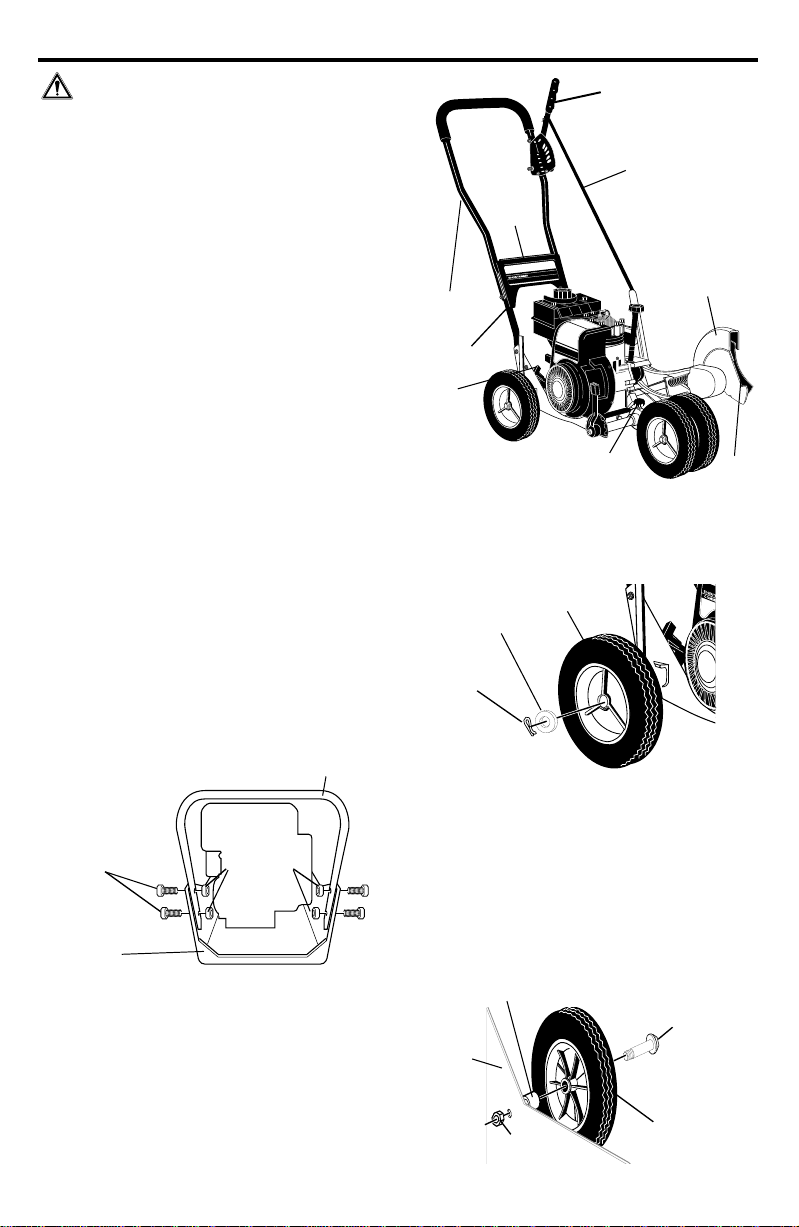
Fig.1-ASSY to the right shows the Edger/
Trimmer completely assembled.
References to the right or left hand side of the
Edger/Trimmer are from the viewpoint of the
operator's position behind the unit.
TO REMOVE EDGER/TRIMMER FROM
CARTON
• Remove the lower handle, control rod, upper handle and packing material from the
carton.
Handle
• Remove wheels, parts bag and packing
material from the carton.
• Cut down all four corners of the carton.
• Remove packing material from around
Edger/Trimmer blade.
TO ASSEMBLE THE EDGER/TRIMMER
NOTE
: Lower handle should be attached first
as it is difficult to attach lower handle with the
wheels on.
• Place lower handle inside the Edger/Trim-
mer frame as shown in Fig. 2-ASSY and
secure in place with four 5/16-18x5/8 hex
head wide flange screws and four 5/16-18
hex head locknuts found in parts bag. Hold
back on the lower handle as you tighten the
screws. Locknuts should be on the inside of
the frame as shown in Fig. 2-ASSY.
Lower Handle
Clutch Lever
Control Rod
Handle
Panel
Upper
Handle
Lower
Starter
Handle
Knob
FIG. 1-ASSY
VIEW FROM RIGHT REAR WHEEL
Flatwasher
1/2x3/4 inch
Cotter Pin
Wheel
FIG. 3-ASSY
Blade Guard
Blade
5/16-18 X 5/8 inch
hex head wide
flange Screws
Frame
FIG. 2-ASSY
5/16-18
Hex Head
Locknuts
• Attach the right rear wheel to the wheel
support rod of the Edger/Trimmer as shown
in Fig. 3-ASSY with a 1/2 x 3/4 inch
flatwasher and cotter pin found in parts bag.
Insert cotter pin and bend ends of cotter pin
with pliers.
• Attach the left rear wheel to the Edger/
Trimmer shown in Fig. 4 -ASSY with a 3/816 x 1.40 inch shoulder bolt, spacer and
3/8-16 hex head whiz lock nut found in parts
bag and tighten nut.
VIEW FROM INSIDE LEFT REAR WHEEL
Spacer
Frame
4
(.70 inch long)
3/8-16 Hex Head
Whiz-lock Nut
FIG. 4-ASSY
Shoulder Bolt
3/8-16x1.40
Wheel
Page 5

• Attach the front wheels to the Edger/Trimmer shown in Fig. 5-ASSY with a 5/16-18
x 4.50 inch hex head screw, four 11/32 x
11/16 inch flatwashers, two spacers and a
5/16-18 hex head wide flange locknut found
in parts bag. Note position of wheels in Fig.
5-ASSY.
Flatwasher
11/32x11/16
5/16-18 Wide
Flange Locknut
Flatwasher
11/32x11/16
5/16-18x4.50
Hex Head Screw
VIEW FROM FRONT
Flatwasher
Spacer
(1.39 Inch Long)
Wheel
FIG. 5-ASSY
• Place the handle panel on the inside of
lower handle. Hold in place while placing
the upper handle on the lower handle as
shown in Fig. 6-ASSY. Align holes in upper
handle, lower handle and handle panel,
secure in place with four 5/16-18 x 1-5/8
inch carriage bolts and four 5/16-18 hex
head locknuts found in parts bag. Locknuts
should be to the inside of the handle panel
as shown.
• The clutch lever is located on the left hand
side of upper handle when properly installed. Insert one end of the control rod
from left to right through the hole in the
clutch lever and attach with a hair pin
found in parts bags. See Fig. 6-ASSY.
• Place the clutch lever in the first depth
selection hole (forward) and insert the other
end of the control rod through the hole in the
quill support arm. Attach with hairpin found
in parts bag.
• Move the clutch lever to rearmost NEUTRAL position and latch in.
• If it is difficult to get the clutch lever into
NEUTRAL, it may be necessary to loosen
the four screws and nuts holding the
lower handles to the frame as shown in
Fig. 8-ASSY. Pry up (forward) on the
handles only enough to allow the clutch
lever to freely enter the NEUTRAL position.
Re-tighten nuts and screws. When the clutch
lever is in NEUTRAL the quill support arm
should be close to the spacer and screw
behind it as shown in Fig. 7-ASSY.
11/32x11/16
Upper Handles
(in operating position)
First Depth
Selection
Handle Panel
5/16-18x1-5/8
Carriage Bolts
5/16-18 Hex
Head Locknut
Lower
Handle
Quill
Support
Arm
VIEW FROM RIGHT SIDE OF UNIT
Right Side
Lower Handle
Lower Handle
Mounting Bolts
5
Hair Pin
FIG. 6-ASSY
FIG. 7-ASSY
FIG. 8-ASSY
Clutch
Lever
Control
Rod
Hair Pin
Quill
Support
Arm
Spacer
Screw
Page 6

OPERATION
FAST
PRIMER
KNOW YOUR EDGER/TRIMMER
READ THIS OWNER’S MANUAL AND SAFETY RULES BEFORE OPERATING YOUR
EDGER/TRIMMER. Compare the illustrations with your EDGER/TRIMMER to familiarize
yourself with the location of various controls and adjustments. Save this manual for future
reference.
Throttle
Control
Starter
Handle
Adjustable Rear
Wheel
Fast
Clutch Lever
Control Rod
Fuel
Cap
Adjustable Front
Wheel
Slow
Oil Fill Cap/
Dipstick
Blade
Guard
FIG. 1-OP
Stop
VIEW OF ENGINE NEAR AIR FILTER
Primer Button
Primer Button
VIEW OF BLADE AREA
Blade
Index Lever
Throttle Control – Used to control the engine
speed.
Primer Button – Injects fuel directly into the
carburetor manifold for faster starts.
Starter Handle – The engine on this Edger/
Trimmer is equipped with an easy pull recoil
starter.
Clutch Lever – Used to start and stop the
blade and control the depth of cut.
Blade Guard – Used to prevent stones or
other material from being thrown at the operator.
Index Lever – Permits adjustment from the
edging (vertical) position to trimming (horizontal) position. To change position, pull the index
lever and rotate the quill assembly to the
desired angle or position.
Adjustable Rear Wheel – Right rear wheel is
adjustable to level Edger/Trimmer when edging along a curb(curb-hopping).
Adjustable Front Wheel – Front wheel is
adjustable from side-to-side for balance. Also,
can be adjusted down for curb-hopping .
6
Page 7

HOW TO USE YOUR EDGER
FAST
PRIMERPRIMER
WARNING
: The operation of this Edger/
Trimmer can result in foreign objects being
thrown into the eyes, which can cause severe
eye damage. Always wear safety glasses or
eye shields while operating the Edger/Trimmer.
We recommend standard safety glasses or
Wide Vision Safety Mask for over your glasses.
TO STOP EDGER/TRIMMER
• To stop the engine, make sure the clutch
lever is all the way back or up and move the
throttle control lever to the STOP positon.
CAUTION: Never leave the Edger/Trim-
mer unattended while the engine is running.
Always disengage the cutting blade and stop
the engine.
TO USE THROTTLE CONTROL
• Run at full engine speed during normal use.
• Push throttle control lever up to increase
speed; down to decrease speed.
TO USE PRIMER BUTTON
• Push primer button five times. See Fig.-
1-OP for location. Wait about two seconds
between each push.
• Do not use primer button to restart
a warm engine after a short shutdown.
TO USE THE CLUTCH LEVER
• Start the engine and move the clutch lever
forward or down to engage the cutting blade.
• Select the edging depth you need. There
are 5 selections up to 2-3/4 inches deep.
IMPORTANT
: If very deep edging is re-
quired, we recommend that a shallow cut
be made first, then cuts at greater depths
until the desired depth is obtained.
TO USE THE INDEX LEVER
(TRIMMING OPERATION)
• Stop engine and disconnect the spark
plug wire from the spark plug.
• Loosen the knob shown in Fig. 1-OP on
the front wheel arm and slide the wheel
all the way to the right side.
• Tighten the knob securely.
CAUTION: The front wheel must be in
the extreme right position to prevent the
blade from striking wheel while in trimming
position.
Knob
FIG. 1-OP
• Pull the index lever out of its notch as
shown below and position it in the notch
marked 90°. See Fig. 2-OP.
• Reconnect the spark plug wire and start
the engine. Move the clutch lever to the
desired trimming height.
Index Lever
INDEX LEVER IN THE NOTCH MARKED "90"
FIG. 2-OP
TO USE CURB-HOPPING FEATURE
The adjustable front and right rear wheel
feature permit the Edger/Trimmer to be used
on an uneven surface such as a curb as
shown in Fig. 3-OP.
• Stop the engine and disconnect the
spark plug wire from the spark plug.
• Loosen the knob on the front wheel arm
bracket and slide the wheel to the best
position to clear the curb and balance the
unit.
• Tighten the knob securely.
• Using the curb height adjust lever, lower
the front wheel to a position that places
the Edger/Trimmer level with the left rear
wheel on the uneven curb surface.
7
Page 8

• Loosen T- knob on the inside right rear
of the main frame that secures the wheel
support rod as shown in Fig. 4-OP.
• Slide the rear wheel down until the Edger/
Trimmer is level when the left wheel is on
the curb.
• Tighten the T-knob securely.
• Reconnect the spark plug wire and start
the engine. The depth of cut adjustment
is the same as described in Edging
Operation paragraph.
Front Wheel Arm
T-Knob
(Behind
Wheel)
Rear
Wheel
Support
Rod
Curb Height
Adjust Lever
FIG. 4-OP
Bracket
Knob
Blade
Guard
• Remove the oil fill cap-dipstick and fill the
crankcase to FULL line on dipstick. See Fig.
5-OP. Check frequently when filling the
crankcase.
NOTE: Engine may already contain some
residual oil.
• Fill the engine crankcase, pouring slowly.
DO NOT OVERFILL. For approximate capacity see your engine manual.
• Tighten the fill cap-dipstick securely each
time you check the oil level.
NOTE: Check oil before each use. Add if
needed.
NOTE: Change oil after the first (2) operating
hours and every (25) operating hours thereafter.
Front
Wheel
Fuel Fill Cap
Oil Fill CapDipstick
CAUTION: Keep away from the
rotating blade. The blade can cause injury.
BEFORE STARTING ENGINE
PRE-USE CHECK OF CONTROLS
All controls should be checked for proper
function before servicing or starting the engine.
• Move the clutch lever into all six positions
in the selector plate. Make sure the clutch
lever snaps into all six holes.
• Return the clutch lever to the rearmost
hole in the selector plate.
FILL/ADD OIL:
This Edger/Trimmer was shipped with little or
no oil in the engine. Oil must be added
before engine is started. DO NOT OVERFILL.
TO ADD ENGINE OIL
• Place the Edger/Trimmer on a level surface.
FIG. 5-OP
FILL GAS
Fill the fuel tank with clean, fresh, unleaded
grade automotive gasoline. Do not use Ethyl,
high octane gasoline or gasohol. Be certain
container is clean and free from rust or other
foreign particles. Never use gasoline that
may be stale from long periods of storage in
the container. If you should run out of gas
while using the Edger/Trimmer, you must be
certain to fill the gas tank completely or the
engine will not restart. CAUTION: DO NOT
use gasoline containing any amount of
alcohol as it can cause serious damage or
significantly reduce performance.
CAUTION: Never fill the gas tank while
the engine is running or hot. Immediately wipe
off any spilled gasoline before attempting to
start the engine.
8
Page 9

TO START THE ENGINE
Before starting the engine, be sure you have
read and understood all the instructions on
the preceding pages. The Edger/Trimmer is
equipped with a recoil starter. The operation
of the engine is controlled by the throttle
control lever.
• Pull the clutch lever all the way back or up
to the rearmost hole to raise and disengage
the blade.
• Move the throttle control lever, see Fig. 1-
OP, to the FAST position.
• Push primer button five times, see Fig. 1-
OP. Wait about two seconds between each
push.
: Do not use primer button to restart a
NOTE
warm engine after a short shutdown.
• To start engine, grasp the engine starter
handle firmly with your right hand.
• Hold the handle firmly with your left hand.
• Pull up sharply on the recoil starter handle.
DO NOT allow the starter rope to snap
back, let it rewind slowly while holding the
starter handle. If engine fails to start after
three pulls, push primer button two times
and pull starter rope again.
• When the engine starts, push throttle
control lever up to increase speed; down
to decrease speed. Run at full engine
speed during normal use.
NOTE: The cutting blade speed is controlled by the engine speed. To reduce the
cutting blade speed, push down on the
throttle control lever. To increase the blade
speed, push the throttle control lever up.
• To stop the engine, make sure the clutch
lever is all the way back or up and move
the throttle control lever to the STOP
position.
CAUTION: Never run the engine in-
doors or in a poorly ventilated area. Engine
exhaust contains carbon monoxide, an odorless and deadly gas. Keep hands, feet, hair
and loose clothing away from any moving
parts on the engine or edger/trimmer. Avoid
the muffler and surrounding areas. Temperatures may exceed 150° F.
EDGING TIPS
• Edging is best performed when conditions
are dry. If the soil is to wet, dirt becomes
packed in and around the blade causing
premature belt wear and decreased performance.
• If dirt does become packed around the blade,
stop the engine, remove the spark plug wire,
and remove the packed debris before continuing to edge. Always wear gloves when
working on blade.
• If very deep edging is required, we recommend that a shallow cut be made first, then
cuts at greater depth until the desired depth
is obtained.
• Uniform edging can be performed when the
blade guide rides on and against the surface
which you are edging.
• Edging can be customized by varying the
number of passes and by the distance your
blade is from the surface you are edging.
MAINTENANCE
SERVICE
RECORDS
Fill in dates as
you complete
regular service
Lubricate all Pivot Points
Lubricate Wheel Axles
Check Engine Oil Level
Change Engine Oil
Replace Air Cleaner Filter
Check Spark Plug
Check Drive Belt
Tighten All Screws and Nuts
Check Blade Wear/Damage
Lubricate Quill Rod
After
First
2
Hours
Before
Each
Use
Frequently
SCHEDULE
Every
Every
10
5
Hours
Hours
9
Every
25
Hours
Begin
Each
Season
Before
Storage
SERVICE
DATES
Page 10

GENERAL RECOMMENDATIONS
The warranty on this Edger/Trimmer does not
cover items that have been subjected to operator abuse or negligence. To receive full
value from the warranty, the operator must
maintain the Edger/Trimmer as instructed in
this manual. The above chart is provided to
assist the operator in properly maintaining the
Edger/Trimmer.
LUBRICATION
• After each 25 hours of use of your Edger/
Trimmer, apply light machine oil to all
moving parts, particularly the wheels.
• The oil in the engine crankcase must be
changed after the first 2 hours of operation and after each 25 hours of use thereafter. See OIL RECOMMENDATIONS in
OPERATIONAL sectional in this manual.
TO CHANGE OIL
• Disconnect the spark plug wire from the
spark plug.
• Remove the oil drain plug as shown in Fig.
1-MAINT and drain the oil into a flat pan.
• After draining all the oil, reinstall the oil
drain plug securely.
NOTE: The oil will drain more freely when the
engine is warm.
VIEW FROM REAR
Oil Drain Plug
FIG. 1-MAINT.
AIR CLEANER
Replace the filter once a year; more often
under dusty or dirty conditions. DO NOT at-
tempt to clean or oil the air filter.
To install a new air filter, do the following:
• Disconnect the spark plug wire from the
spark plug.
• Turn the cover as shown in Fig.-2 MAINT.
to the left counterclockwise and remove the
cover and the air filter from the flange.
• Discard the air filter.
• Clean the cover and the flange thoroughly.
• Insert the new air filter into the cover.
• Push the cover firmly against the flange
and turn it to the right clockwise as far as
it will go as shown in Fig. 2-MAINT below.
Be sure the retainers are locked around the
flange.
• Reconnect the spark plug wire.
Turn cover to the left
(counterclockwise)
to remove
Flange
Filter
Retainer
Cover
Slot
Tab
Turn cover to the right
(clockwise) to install
FIG. 2-MAINT.
CAUTION: Never run the engine with-
out the air cleaner element installed. A defective air cleaner can result in loss of engine
power and can cause excessive wear or
damage to the engine components if dirt or
dust is permitted to enter the engine through
the carburetor. A damaged air cleaner, or
one that is clogged with dust or dirt should be
replaced immediately.
SPARK PLUG
Clean the spark plug and reset the gap periodically. Before removing spark plug, clean
the area around its base to prevent dirt from
entering into the engine. Replace the spark
plug if the electrodes are pitted or burned or if
the porcelain is cracked. Clean the spark plug
by carefully scraping the electrodes with a
knife or screwdriver (do not sand blast or use
a wire brush). Be sure the spark plug is clean
and free of foreign material. Check the electrodes gap with a wire feeler gauge and reset
to .030" if necessary. If a new spark plug is
needed, refer to the Engine manual for the
proper replacement spark plug.
Before reinstalling the spark plug, coat the
threads lightly with graphite or light oil to
insure easy removal. Tighten the spark plug
firmly into the engine. If a torque wrench is
available, torque the spark plug to 15 footpounds.
10
Page 11

CAUTION: Always stop the engine
and disconnect the spark plug wire before
making any repairs to the Edger/Trimmer.
V-BELT REPLACEMENT
Your Edger/Trimmer is equipped with a V-belt
made of a special compound. If the belt becomes worn or breaks, replace it with an
orignal equipment belt as shown in the Repair
Parts section of this manual. Never use a
substitute.
• Disconnect the spark plug wire.
• Put the clutch lever back or up to release the
tension from the belt.
• Remove the two top screws from the engine
pulley cover as shown in Fig 1-SERV&
ADJ and remove the cover. Make sure you
do not lose the spacer on the rear screw.
Screw
Spacer
V-Belt
Belt
Guide
Front
Screw
Engine
Pulley Cover
Engine Pulley
Cover Screws
FIG. 1-SERV & ADJ
• Remove the front screw securing the belt
guide as shown in Fig. 1-SERV& ADJ , to
the engine. Swing the belt guide away from
the belt.
• Remove the three screws from the belt
guard as shown in Fig. 2- SERV & ADJ.
• Remove the belt from the engine and quill
assembly pulleys and install the new belt.
• Install and secure front belt guard.
• Secure the belt guide loosened earlier.
• Reinstall the engine pulley cover and re-
connect the spark plug wire.
Engine
Pulley
Control
Lever
Stop
Spacer
SERVICE AND ADJUSTMENTS
Belt
Guard
Belt Guard
Screws
FIG. 2-SERV & ADJ
BLADE REPLACEMENT
The cutting blade is subject to wear and
damage such as nicks and dents. This will not
generally affect its function.
This blade is specially designed to not require
sharpening. Do not attempt to sharpen this
blade. The blade is reversible. If the nicks and
dents are excessive, remove the blade, turn it
around and reinstall. This will provide a fresh
cutting edge. The blades should be replaced
if both sides are worn and damaged. If any
cracks are evident, replace the blade immediately.
CAUTION: When removing or tighten-
ing the blade nut, always use the method
shown in Fig. 3- SERV & ADJ. The holding
wrench must always be positioned on the nut
behind the cutting blade.
CAUTION: Do not attempt to sharpen
this blade. Sharpening could damage it and
cause it to break, which may further result in
injury to yourself or a bystander.
To replace the blade, do the following:
• Always wear gloves when handling the
blade.
• Disconnect spark plug wire.
• Remove the 1/2-20 locknut shown in Fig. 3-
SERV & ADJ securing the blade to the
drive shaft.
• Remove the blade.
• Install the new blade and reinstall nut.
Tighten the nut securely.
• Reconnect the spark plug wire.
11
Page 12

Tightening
Wrench
Holding
Wrench
Blade
FIG. 3-SERV & ADJ
Locknut
TO ADJUST CARBURETOR
The carburetor shown below has been pre-set
at the factory and readjustment should not be
necessary. If you think your carburetor needs
CAUTION: Never store your Edger/
Trimmer indoors or in an enclosed, poorly
ventilated area. If gasoline remains in the
tank fumes may reach an open flame, spark
or pilot light from a furnace, water heater,
clothes dryer, cigarette, etc. and ignite.
EDGER/TRIMMER
• Clean the Edger/Trimmer thoroughly;
remove all debris and wipe the unit dry.
• Inspect the Edger/Trimmer for worn or
damaged parts and tighten all loose
hardware.
• Oil all points described in the Lubrication
paragraph in the Maintenance section of
this manual.
• Store the Edge/Trimmer in a protected
area and cover for additional protection.
IMPORTANT
: A yearly checkup or tune-
up by a Service Center is a good way of
ensuring that your Edger/Trimmer will
provide maximum performance for the
next season.
ENGINE
IMPORTANT: It is important to prevent pre-
vent gum deposits from forming in essential
fuel system parts such as the carburetor, fuel
filter, fuel hose, or tank during storage. Also,
experience indicates that alcohol-blended
fuels called gasohol or using ethanol or methanol can attract moisture which leads to separation and formation of acids during storage.
Acidic gas can damage the fuel system of an
engine while in storage.
adjusting, see your nearest Authorized Service Center.
IMPORTANT
: Never tamper the engine
governor, which is factory set for proper
engine speed. Overspeeding the engine
above the factory high speed setting can
be dangerous. If you think the engine-governed high speed needs adjusting, contact
your nearest Service Center which has the
proper equipment and experience to make
any necessary adjustments.
STORAGE
To prevent engine damage (if Edger/Trimmer
is not used for more than 30 days)follow the
steps below.
• To remove gasoline, run the engine until
the tank is empty and the engine stops.
• If you do not want to remove gasoline, a
fuel stabilizer may be added to any gasoline left in the tank to minimize gum deposits and acids. If the tank is almost empty,
mix stabilizer with fresh gasoline in a
separate container and add some to the
tank. Always follow instructions on
stabilizer container. Then run engine at
least 10 minutes after stabilizer is added
to allow mixture to reach carburetor.
Store Edger/Trimmer in a safe place. See
IMPORTANT under STORAGE (ENGINE).
• Store the Edger/Trimmer in the wheelsdown, operating position. If the Edger/
Trimmer is stored in any other position, oil
from the crankcase could enter the
cylinder, causing a service problem.
• You can keep your engine in good oper-
ating condition during storage by:
• Changing oil.
• Lubricating the piston/cylinder area. This
can be done by first removing the spark
plug and squirting clean engine oil into the
spark plug hole. Then cover the spark plug
hole with a rag to absorb oil spray. Next,
rotate the engine by pulling the starter two
or three times. Finally,reinstall spark plug
and attach spark plug wire.
• Spray a light oil around the top of the tube
the quill rod extends through and work the
oil in with the clutch lever. This will prevent
the quill assembly from sticking to the tube
next season.
12
Page 13

TROUBLE SHOOTING
TROUBLE
Difficult starting
or
Engine runs
erratic
Cutting blade
fails to turn
Blade fails to cut
properly
Excessive
vibration
CAUSE
Stale fuel
Defective spark plug
Clogged fuel line
Blocked fuel line or empty fuel tank
Carburetor out of adjustment
Fouled spark plug
Clogged air cleaner
Jammed due to foreign object
Loose blade
Defective belt
Defective quill bearings
Quill rod sticking
Damaged or worn blade
Loose parts
CORRECTION
Drain fuel tank. Fill with fresh
fuel
Clean and re-gap or replace
Replace fuel filter
Clean fuel line; check gas tank
Have carburetor adjusted
Clean and adjust gap, or replace
Tap clean or replace air cleaner
Clear obstruction
Tighten blade retaining nut
Replace V-belt
Replace the bearings
Lubricate tube and rod
Replace blade
Stop engine immediately; tighten
all bolts. If vibration continues,
take the unit into the nearest Service Center
13
 Loading...