

Page 1

sTarTInG anD sTOppInG
See chapters 4.3 and 4.4 in the Operator’s Manual.
stA rti ng
5
1. Open the hatch by pressing the STOP button.
2. Set the main switch to position 1. When you do this for
the rst time, a start up sequence starts where you select
a four digit PIN code among other things.
3. Press the START button.
4. Close the hatch.
stopping
Press the STOP button.
TEsT DOCKInG anD aCCEssIbIlITy
See chapters 3.6 and 6.8 in the Operator’s Manual.
Here you can nd a number of tips relating to the positioning of the guide wire in narrow passages as well as
settings for the mower’s behaviour in narrow passages.
6
test docking
1. It is important that the robotic lawnmower can easily dock
with the charging station to ensure safe operation. Use the
Installation > Find charging station > Overview > Test function to
test this. If the robotic lawnmower has difculty docking,
the position of the charging station must be reviewed.
See chapter 3.2 in the Operator’s Manual.
3
test Accessibility
2. Narrow passages in the garden make it difcult for the
robotic lawnmower to nd the charging station. Use the
Installation > Lawn coverage > Overview > Test function to test
that the robotic lawnmower can travel through the
narrowest passage. If the test fails, the position of the guide
wire must be reviewed and possible manual setting changes
made. See chapters 3.6 and 6.8 in the Operator’s Manual.
aDjusTInG THE rObOTIC laWnMOWEr
TO suIT yOur GarDEn
See chapter 6 in the Operator’s Manual.
7
Adjusting the robotic lAwnmower to suit
the size of your lAwn
The mowing results depend on mowing time. Adjust the
mowing time to suit your garden using the Timer function.
If the robotic lawnmower cuts too much: The lawn will
look trampled.
If the robotic lawnmower cuts too little: The lawn will not
be properly mown.
Here you will nd some tips on important settings for your robotic lawnmower.
All settings for your robotic lawnmower are made via the menu functions.
2
1
timer
You decide what times during the day the robotic lawnmower
is to work. The robotic lawnmower mows about 135 m² per
hour and day (approx. 90 m² for Automower® 320). For
example; if your garden consists of 1,200 m² of lawn, the
robotic lawnmower should work on average 9 hours per day
(13 hours for Automower® 320).
115 49 25-26
AUTOMOW ER® is a trademark owned by Husqvarna AB. Copyright © 2013 HUSQVARNA. All rights reserved.
www.automower.com
quICK GuIDE
Husqvarna auTOMOWEr
320/330X
®
Page 2
GETTInG sTarTED WITH
Husqvarna’s rObOTIC laWnMOWEr
1
2
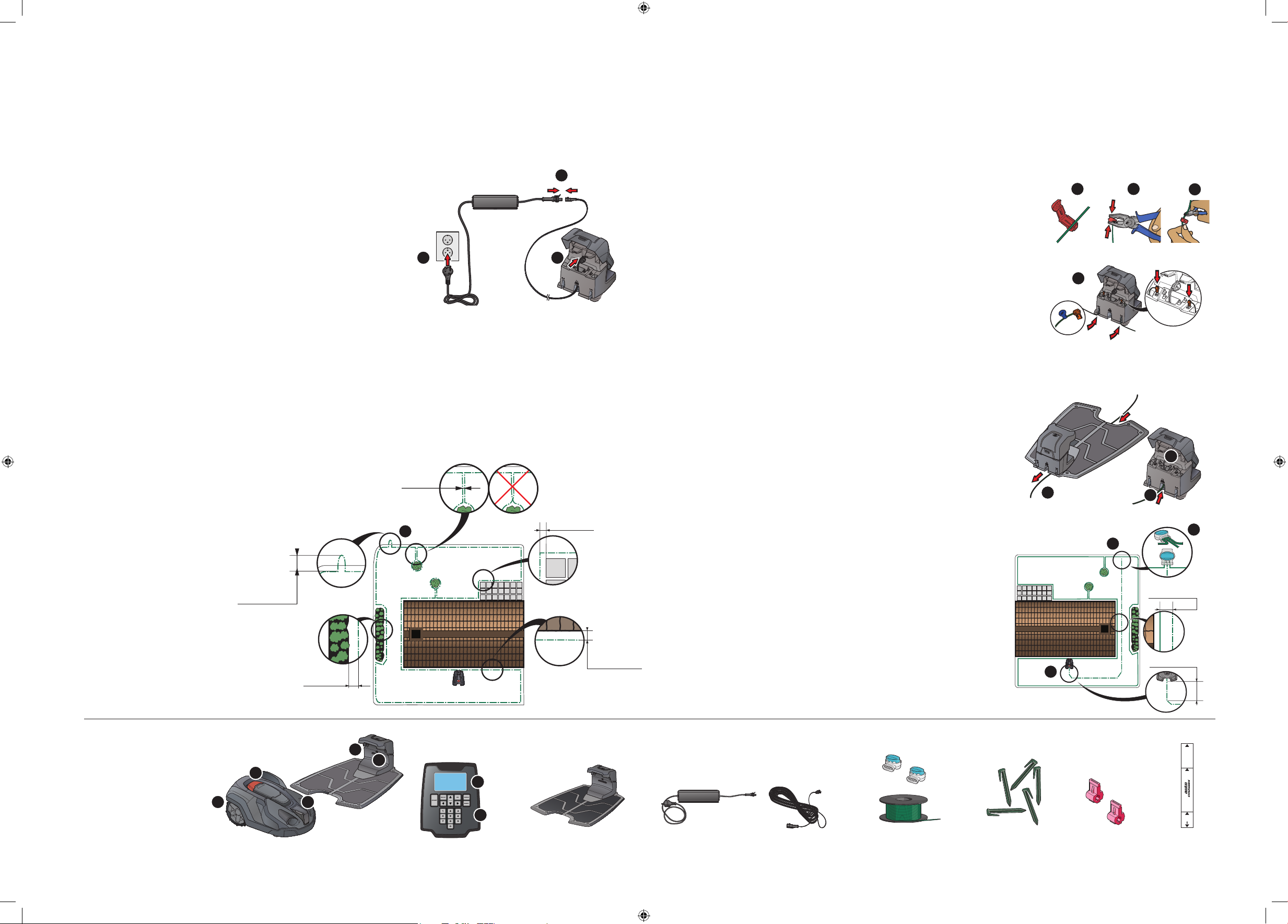
plaCEMEnT Of anD COnnECTInG
THE CHarGInG sTaTIOn
See chapter 3.2 in the Operator’s Manual.
1. Place the charging station at a central position in the
working area, with a lot of open space in front of the
charging station and on a relatively horizontal surface.
2. Connect the transformer’s low voltage cable to the
charging station and the transformer.
3. Connect the transformer to a 230 V wall socket.
CHarGInG THE baTTEry anD plaCEMEnT
Of THE bOunDary WIrE
See chapters 3.3 and 3.4 in the Operator’s Manual.
1. Place the robotic lawnmower in the charging
station to charge the battery while the boundary
wire is laid. Set the main switch to position 1.
2. Lay the boundary wire so that it forms a loop
around the working area.
3. Make an eyelet at the point where the guide wire
will be connected later (see step 4.5).
10 cm/4”
30 cm/12”
0 cm/0”
3
2
13
10 cm/4”
35 cm/14”
3
4
COnnECTInG THE bOunDary WIrE
See chapter 3.5 in the Operator’s Manual.
1. Open the connectors and lay the wire ends in the recesses
on each connector.
2. Press the connectors together using a pair of pliers.
3. Cut off any surplus boundary wire. Cut 1 to 2 cm above
the connectors.
4. Press the connectors onto the contact pins, marked A, on
the charging station. It is important that the right-hand
wire is connected to the rig ht-hand contac t pin, and the
left-hand wire to the left-hand pin.
plaCEMEnT Of anD COnnECTInG
THE GuIDE WIrE
See chapter 3.6 in the Operator’s Manual.
1. Narrow passages in the garden make it difcult for the
robotic lawnmower to nd the charging station. The
robotic lawnmower can be lead to remote garden areas
using the guide wire. The guide wire also helps the
robotic lawnmower to quickly nd the charging station.
2. Lay the guide wire under the charging station and at
least 2 metres straight out from the front edge of the
charging station.
3. Run the guide wire to the point on the boundary wire
the connection will be made. Avoid laying the wire at
tight angles.
4. Cut the boundary wire with a wire cutters at the centre
of the eyelet that was made in step 2.3.
5. Connect the guide wire to the boundary wire using the
accompanying couplers. Press the coupler completely
together with a pair of pliers.
6. Fit a connector to the other end of the guide wire. Fasten
the connector to the contact pin marked G1 on the
charging station.
21
4
2
3
2
2
min 30 cm/12”
min 2 m/7 ft
3
7
5
1. Main switch
2. STOP button
3. Charging strip
4. LED for function check of the
boundary and guide wires
5. Display
6. Keypad
3
4
2
1
3
5
6
Charging station
Transformer Low voltage cable Boundary wire and couplers Pegs Connectors Measurement gauge
30 cm
20 cm
5 cm
 Loading...