

Page 1
Rid er 11/ 1 3
Rider 11 Bio/13 Bio
Operator´s manual
Please read these instructions carefully and make sure
you understand them before using the machine.
101 91 58-26
Page 2

CONTENTS
Operator’s Manual for
Rider 11 and Rider 13
Rider 11 Bio and Rider 13 Bio
Introduction .........................................................2
Driving and transport on public roads .............. 2
Towing..............................................................2
Use...................................................................2
Serial number...................................................3
Explanation of symbols......................................4
Safety instructions..............................................5
General use .....................................................5
Driving on slopes .............................................6
Children............................................................7
Maintenance ....................................................7
Presentation ........................................................9
Location of the controls....................................9
Throttle/Choke lever.......................................10
Drive disengagement lever ............................ 10
Parking brake.................................................10
Throttle pedal ................................................. 11
Cutting unit.....................................................12
Lift lever for cutting unit..................................12
Lever for adjustment of cutting height............13
Seat................................................................13
Fuelling ..........................................................13
Driving................................................................14
Before starting................................................14
Starting the engine.........................................14
Driving the machine ....................................... 14
Cutting tips .....................................................17
Stopping the engine .......................................18
Drive disengagement lever ............................ 18
Maintenance ......................................................19
Maintenance schedule ...................................19
Dismantling of the machine hoods.................20
Checking and adjusting the steering wires ....22
Checking and adjusting the brakes................23
Checking and adjustment of throttle wire.......24
Replacement of fuel filter ............................... 24
Replacement of air filter .................................25
Checking the fuel pump’s air filter..................26
Checking the battery acid level ......................26
Checking the safety system ...........................27
Checking the tyre pressure ............................28
Checking the engine’s cooling air intake........28
Checking and adjusting the cutting unit
ground pressure.............................................29
Checking the parallelism of the cutting unit ...29
Adjusting the parallelism of the cutting unit....30
Service position for BioClip 90 .......................31
Checking the blades ......................................34
Replacing the break-pin .................................34
Changing the oil .............................................35
Lubrication.........................................................35
Checking the engine’s oil level.......................35
Checking the transmission’s oil level ............. 36
Lubricating the belt adjuster...........................36
General lubrication.........................................36
Lubrication of front wheel bearings ................37
Trouble shooting schedule ..............................38
Storage...............................................................39
Winter storage................................................39
Service ...........................................................39
Technical data ...................................................40
IMPORTANT INFORMATION
Read through these instructions carefully so that you know how to use and maintain the
machine before using it.
For servicing other than described in this manual contact an authorised dealer for parts and
service.
English – 1
Page 3

INSTRUCTION
Dear customer
Thank you for choosing a Husqvarna Rider. Husqvarna Riders are built to a unique design with a frontmounted cutting unit and a patented rear-wheel steering system. Riders are designed for maximum efficiency
even in small or confined areas. The closely grouped controls and pedal-operated hydrostatic transmission
(certain models) also contribute to the performance of this machine.
We hope you will find this operator’s manual very useful. By following its instructions (on operation, service,
maintenance, etc.) you will significantly extend the life of the machine and even its second-hand value.
When you sell your Rider, make sure you pass on the operator’s manual to the new owner.
Travel and transport on public roads
Check the relevant road traffic regulations before driving the machine on a public road. If transporting the
machine on another vehicle always use approved securing devices and make sure that the machine is
securely held.
Towing
When your machine is equipped with a hydrostatic transmission you should, if necessary, only tow the
machine over short distances and at a low speed, otherwise there is a risk of damaging the transmission.
Intended use
This machine is designed solely for cutting grass on conventional lawns and other cleared and leveled
ground without obstacles, as rocks, stumps etc., and, in conjunction with accessories supplied by the
manufacturer even for other special tasks for which instructions are delivered with the accessory. Use in any
other way is considered as contrary to the intended use. Compliance with and strict adherence to the
conditions of operation, service and repair as specified by the manufacturer also constitute essential
elements of the intended use.
This machine should be operated, serviced and repaired only by persons who are familiar with its particular
characteristics and who are acquainted with the relevant safety procedures.
Accident prevention regulations, all other generally recognised regulations on safety and occupational
medicine, and all road traffic regulations must be observed at all times.
Any arbitrary modifications carried out to this machine may relieve the manufacturer of liability for any
resulting damage or injury
2 – English
Page 4

SAFETY INSTRUCTIONS
Good service
Husqvarna products are sold all over the world and only through servicing dealers. This is to ensure that you,
the customer, get the best support and service. Before the machine is delivered it undergoes inspection and
is adjusted by your dealer.
When you need spare parts or advice on service issues, warranty terms, etc., contact:
This Operator’s Manual belongs to
machine with serial number:
Engine Transmission
Serial number
The serial number can be found on the printed plate attached to the front, left-hand side under the seat.
Stated on the plate, from the top are:
• The machines type designation.
• The manufacturer’s type number.
• The machine’s serial number.
State the type designation and serial number when ordering spare parts.
The engine number is punched on a plate that is riveted to the fan cover. The plate states:
• Model.
• Type.
• Code.
Please state these when ordering spare parts.
The transmission’s serial number is stated on the barcode decal located on the front of the housing on the
left-hand drive axle:
• Type designation is stated above the barcode and starts with the letter “K”.
• The serial number is stated above the barcode and has the prefix “s/n”.
• The manufacturer’s type number is stated under the barcode and has the prefix “p/n”.
State the type designation and serial number when ordering spare parts.
English – 3
Page 5

EXPLANATION OF SYMBOLS
These symbols are on the machine and in the operator’s manual.
Study them carefully so that you know what they mean.
Read the operator’s manual
R
Reverse Neutral Fast Slow Engine off Battery Choke Fuel
Oil pressure Cutting height Backwards Forwards Ignition Hydrostatic free wheel
Use eye and Clutch in Clutch out Parking brake Brake Clutch Warning
hearing protection
Soundlevel Warning! Warning! Never drive across a slope
N
Rotating blades. Risk that the machine can tip over
European standard for
machine safety
Never use the machine if persons,
especially children, or animals,
are in the vicinity.
4 – English
Never carry passengers on the
machine or equipment.
Starting instructions
Read the instructions
Check the engine’s oil level
Check the hydrostat’s oil level
Lift up the cutting unit
Put the gear shift/hydrostat pedal in
neutral
Brake
If the engine is cold use the choke
Start the engine
Release the parking brake before
driving
Keep hands and feet away
from under the hood when
the engine is running.
Drive very slowly
without the cutting unit.
Speed limiter pedal forwards
Neutral
Speed limiter pedal reverse
Switch off the engine and take
off the ignition cable before
repairs or maintenance
Page 6
RIDER
970
SAFETY INSTRUCTIONS
RIDER
850
RIDER
850
RIDER
850
RIDER
850
These instructions are for your safety. Read them carefully.
This symbol implies that important safety rules are applicable.
This is for your safety and the operating reliability of the machine.
General use:
• Make yourself familiar with the controls and how
to stop quickly.
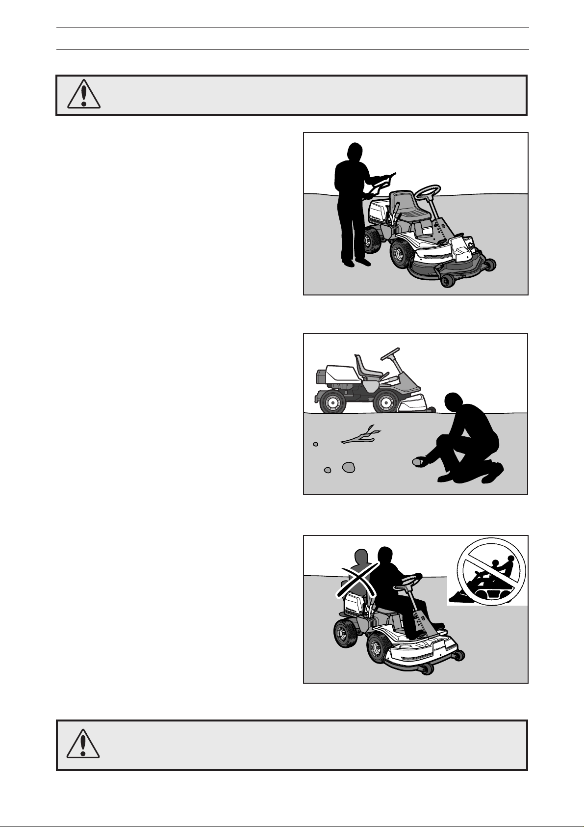
• Read all the instructions in Operator’s Manual
and on the machine before starting it. Make sure
you understand them, and then follow them.
• Only allow adults who are familiar with the
machine to use it.
• Wear approved protective glasses or a visor
during assembly and driving.
• Never use the machine barefoot. Always wear
heavy-duty shoes, preferably toe-capped.
• Never wear loose fitting clothes which can
fasten in moving parts.
R
R
ID
ID
E
E
R
R
9
9
7
7
0
0
Read the instructions before starting the machine.
• Clear the area of objects such as stones, toys,
and wires, etc. which can be caught up by the
blades and thrown out.
• Check that there are no other persons in the
area before starting to cut.
• Stop the machine if anyone comes into the work
area.
• Never carry passengers.
• Do not cut backwards unless absolutely neces-
sary.
• Always look down and behind before and during
reversing.
• Keep an eye on the ejected grass and do not
direct it towards anyone.
• Slow down before turning.
• Never leave the machine unattended when the
engine is running. Always switch off the blades,
pull on the parking brake, stop the engine and
take out the keys before leaving the machine.
• Switch off the blades when you are not cutting.
Clear the area from stones etc. before cutting.
R
R
R
R
ID
ID
ID
ID
E
E
E
E
R
R
R
R
8
8
8
8
5
5
5
5
0
0
0
0
• Only cut in daylight or good artificial lighting.
• Never use the machine when you have con-
sumed alcohol, drugs, or certain medicines.
WARNING!
This machine can cut off hands and feet, and eject objects.
Failure to follow the safety instructions can lead to severe injury.
Never carry passengers.
RIDER 850
RIDER 850
RIDER 850
RIDER 850
English – 5
Page 7
SAFETY INSTRUCTIONS
RIDER
850
RIDER
850
RIDER
850
RIDER
850
• Watch out for traffic when working close to a
road, or crossing one.
• Be careful when rounding a fixed object so that
the blades do not hit it. Never drive intentionally
over a foreign object.
• The machine is heavy and can cause very
severe crush injuries. Be extra careful when
loading it on a trailer or truck.
• Be careful when pulling a load or using heavy
equipment.
a. Only use approved tow hooks.
b. Limit the load to what you can manage safely.
c. Do not make sharp turns. Be careful when
reversing.
d. Use counterweights or wheel weights when
indicated in the instructions.
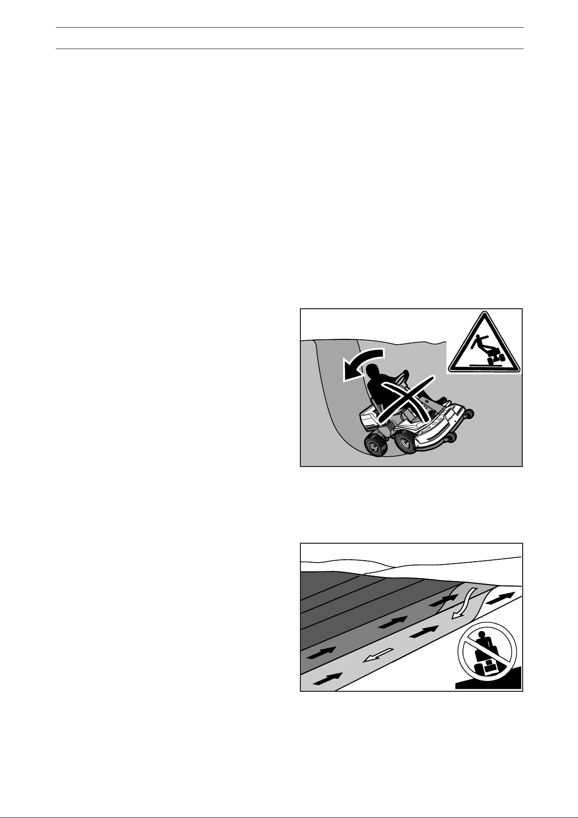
Driving on slopes
Driving on slopes is one of the situations where
there is the most serious risk that the driver can
loose control or that the machine tips over, which
can cause severe injuries or be fatal. All slopes
require extra care. If you cannot reverse up the
slope or if you feel uncertain avoid cutting it.
Do as follows:
• Remove obstacles such as stones and branches
etc.
• Cut upwards and downwards, not sideways.
• Look out for and avoid driving over furrows,
holes or mounds. On uneven surfaces it is
easier for the machine to tip over. High grass
can conceal obstacles.
• Drive slowly. Rider 11: Select a low gear to avoid
having to stop and changing gear. It is also
easier to use the gear to brake in a low gear.
• Follow the manufacturer’s recommendations on
wheelweights or counterweights to increase
stability.
• Take special care with accessories that can alter
the stability of the rider mower.
850
850
850
850
R
R
R
R
E
E
E
E
ID
ID
ID
ID
R
R
R
R
Be extra careful when driving on slopes.
0
0
0
0
5
5
5
5
8
8
8
8
R
R
R
R
E
E
E
E
D
D
D
D
I
I
I
I
R
R
R
R
• Always drive smoothly and slowly on slopes.
Avoid sudden changes of speed or direction.
• Avoid starting or stopping on a slope. If the tyres
begin to skid switch of the blades and drive
slowly down the slope.
• Avoid unnecessary turns on slopes, and if
turning is necessary turn slowly and gradually,
downwards if possible.
6 – English
Cut slopes upwards and downwards, not sideways.
Page 8
SAFETY INSTRUCTIONS
RIDER
970
RIDER
850
RIDER
850
RIDER
850
RIDER
850
• Do not cut close to edges, ditches or banks. The
machine can suddenly tip over if a wheel goes
over the edge of a drop or a ditch, or if a bank
gives way.
• Do not cut wet grass. It is slippery and the tyres
can loose their grip so that the machine slides.
• Do not try to stabilise the machine by placing
one foot on the ground.
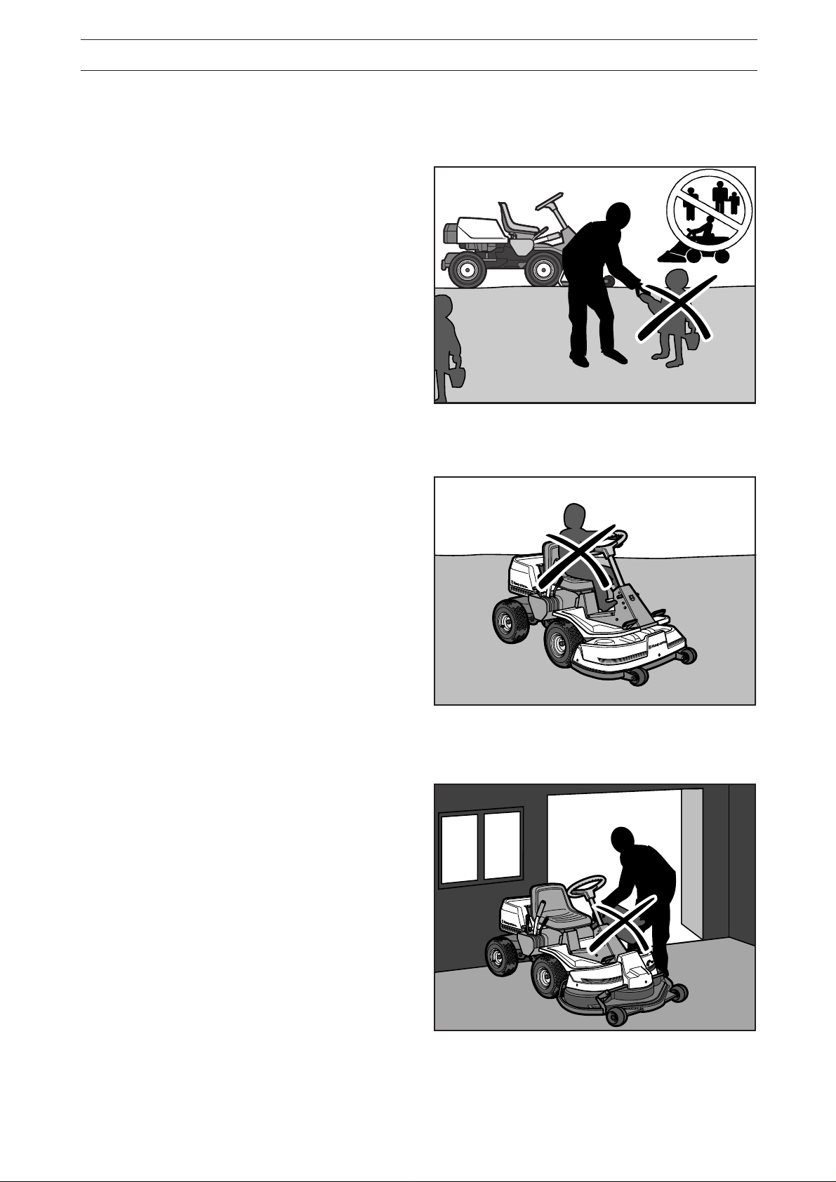
Children
Tragic accidents can occur if the driver does not
pay attention to children in the vicinity. Children are
often attracted to the machine and the work of
mowing. Never assume that children stay where
you last saw them.
• Keep children away from the mowing area and
under the close supervision of another adult.
• Be on your guard and switch off the machine if
children come into the work area.
Keep children away from the mowing area.
• Before and during reversing look behind and
down for small children.
• Never allow children to ride on the machine.
They can fall off and become seriously injured or
obstruct a risky manoeuvre of the machine.
• Never allow children to drive the machine.
• Be extra careful close to corners, bushes, trees
or other objects which obstruct your view.
Maintenance
• Petrol/gasoline and petrol/gasoline fumes are
toxic and highly inflammable. Be extra careful
when handling petrol/gasoline.
a. Store the fuel in containers approved for this
purpose.
b. Never fill up the machine with fuel when the
engine is running. Let the engine cool before
filling up with fuel. Do not smoke, or fill up with
fuel in the vicinity of naked flames or sparks.
Do not smoke. Do not fill fuel in the vicinity of
sparks or naked flames.
R
R
R
R
ID
ID
ID
ID
E
E
E
E
R
R
R
R
8
8
8
8
5
5
5
5
0
0
0
0
Never allow children to drive the machine.
RIDER 850
RIDER 850
RIDER 850
RIDER 850
c. Never fill up with fuel indoors.
d. If leakage has occurred in the fuel system the
engine must not be started until this is rectified.
e. Never store the machine or fuel containers
indoors if there are naked flames, such as in a
boiler room or where there is electrical equipment which can emit sparks.
• Check the fuel level each time before using the
machine, and leave space for the fuel to expand
since the heat from the engine and hot sun can
cause the fuel to run over.
R
R
ID
ID
E
E
R
R
9
9
7
7
0
0
Never fill up with fuel indoors.
English – 7
Page 9
SAFETY INSTRUCTIONS
RIDER
850
RIDER
850
RIDER
970
• Avoid overfilling. If fuel has been spilt on the
Rider wipe it up and wait until it has evaporated
before starting the engine. If fuel is spilt on
clothes, change them.
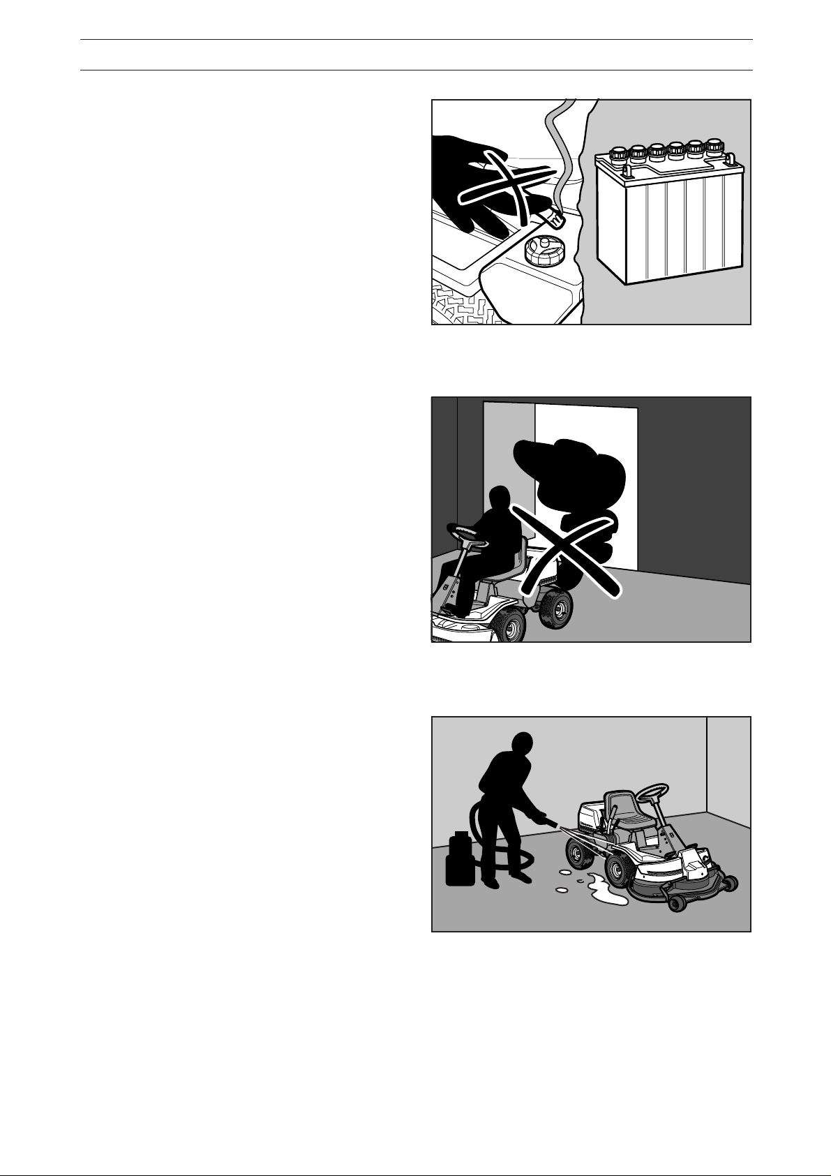
• Be extra careful when handling battery acid.
Spilling acid on the skin can cause severe burn
injuries. Rinse immediately with water. If acid
gets into the eyes this can cause blindness.
Contact a doctor.
• Be careful with the maintenance of the battery.
Explosive gas is formed in the battery. Never
handle the battery when smoking or in the
vicinity of naked flames or sparks. Otherwise the
battery can explode and cause severe injuries.
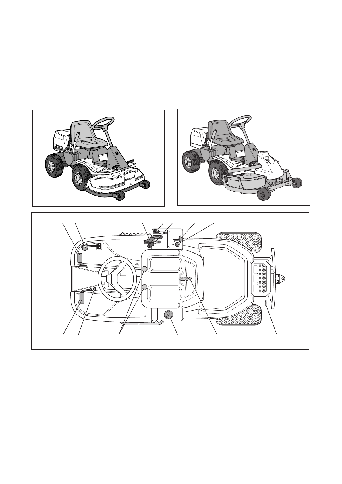
• Never drive the machine in an enclosed space.
The exhaust fumes contain carbon monoxide,
an odourless, non coloured, toxic and fatal gas.
• Make sure that bolts and nuts, especially attachment bolts for the blade units are properly
tightened and that the equipment is in good
order.
Never smoke in the vicinity of the battery or the fuel.
• Never alter the safety devices. Check regularly
that they function. The machine must not be
driven with defective or unmounted safety
devices.
• Do not alter the setting of the governor and do
not race the engine.
• Reduce the fire risk. Keep the machine clean
from grass, leaves and other refuse which
fastens in it. Allow the machine to cool before
placing it in the storage area.
• Stop and inspect the equipment if you drive over
an object. If necessary repair the machine
before starting.
• Never make adjustments with the engine running.
• The machine is tested for safety and approved
only for equipment supplied or recommended by
the manufacturer.
• The blades are sharp and can cause cutting
injuries. Wrap over the blades or use protective
gloves when handling them.
R
R
R
R
I
ID
ID
ID
D
E
E
E
E
R
R
R
R
8
8
8
8
5
5
5
5
0
0
0
0
Never drive the machine in an enclosed space.
R
R
I
I
D
D
E
E
R
R
9
9
7
7
0
0
• Check the functioning of the brakes regularly.
Adjust and maintain them as necessary.
8 – English
Clean the machine regularly from grass, leaves and
other waste.
Page 10
Presentation
PRESENTATION
Congratulation on your choice of a first-class quality
product.
This manual describes four models that are fitted
with engines from Briggs & Stratton of 10.5 and
12.5 horsepower respectively.
6
5
4
Rider 11 and Rider 11 Bio has an in-line gearbox
with five forward gears and one reverse gear.
On the Rider 13 and Rider 13 Bio the power transmission from the engine is handled by a hydrostatic
gearbox which enables stepless variation of the
speed.
3 13
2
1
8
7
9
Location of the controls
1. Ignition lock
2. Throttle/Choke lever
3. Adjustment of cutting height
4. Lifting lever, cutting unit
5. Speed control for reversing (only on 13 and 13
Bio)
6. Speed limiter for driving forwards on 13 and 13
Bio
Parking brake on 11 and 11 Bio
10 11
7. Parking brake on 13 and 13 Bio
Clutch pedal on 11 and 11 Bio
8. Lock button for parking brake (left side on 13
and 13 Bio, right side on 11 and 11 Bio)
9. Seat adjustment
10. Fuel tank cap
11. Main lock (under seat)
12. Lever for disengagement of drive (only on 13
and 13 Bio)
13. Gear lever on 11 and 11 Bio
12
English – 9
Page 11
PRESENTATION RIDER 11 / 11 BIO
Throttle and Choke lever
The engine speed is adjusted with the throttle
control, and thereby also the rotation speed of the
blades.
The control is also used to activate the choke
function. When the choke is used the engine
receives a richer mixture of fuel and air, which
simplifies cold start.
Clutch pedal
The clutch pedal disengages the engine and stops
forward movement.
not
The blades are
affected by the clutch pedal.
Brake pedal / Parking brake
The brake pedal activates a disc brake which is
placed on the gearbox and brakes the drive wheels.
When braking the clutch pedal should also be
pushed down to achieve best braking power.
The brake pedal also operates as a parking brake if
the lock button is pressed in when the pedal is
pressed.
10 – English
Page 12
PRESENTATION RIDER 13/13 BIO
Throttle and Choke lever
The engine speed is adjusted with the throttle
control, and thereby also the rotation speed of the
blades.
The control is also used to activate the choke
function. When the choke is used the engine
receives a richer mixture of fuel and air, which
simplifies cold start.
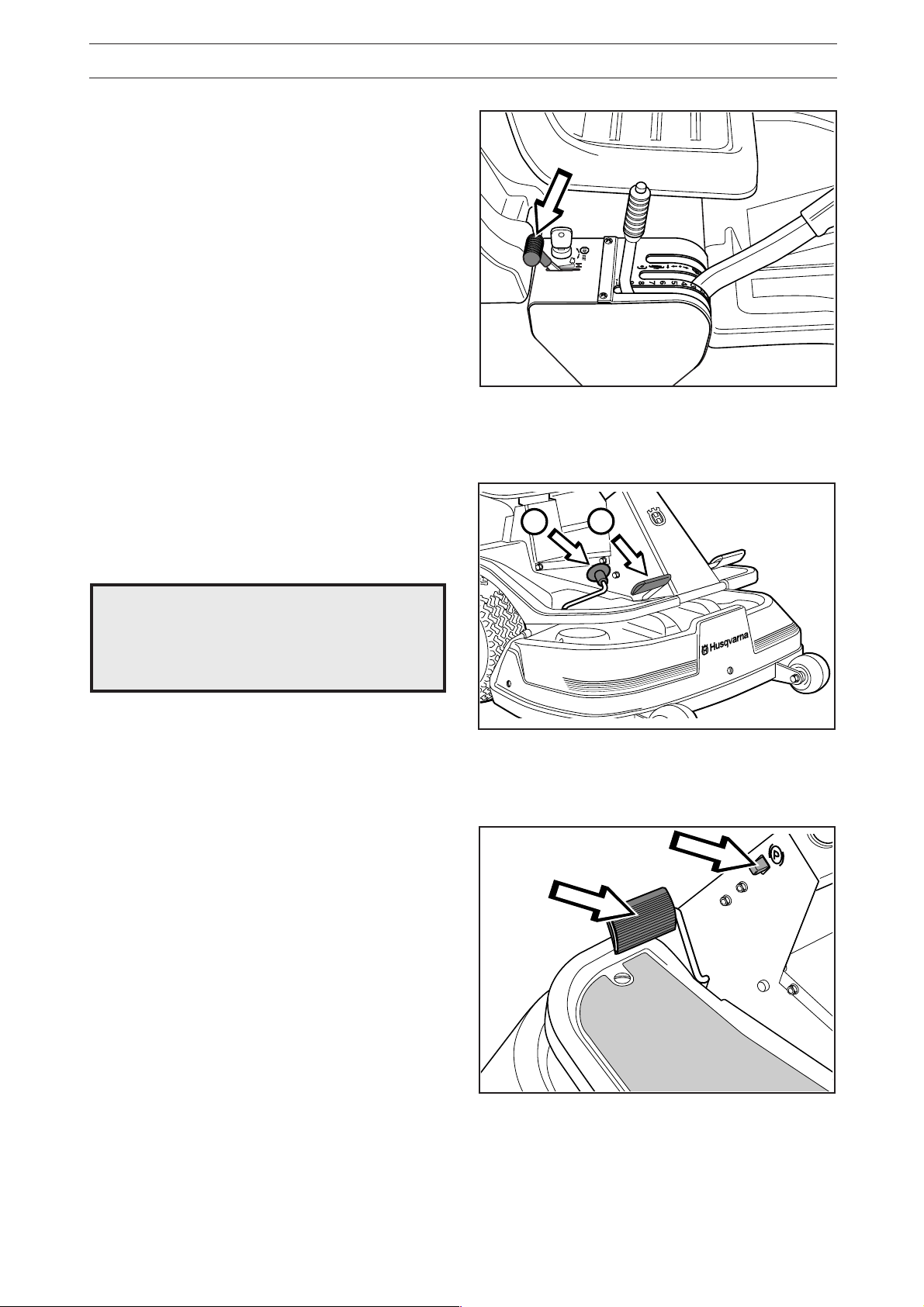
Speed limiter
The speed of the machine is steplessly regulated
with two pedals. Pedal (1) is used to drive forwards
and pedal (2) for reversing.
WARNING!
Make sure that branches do not
!
obstruct the pedals when mowing
under bushes, otherwise you may
lose control.
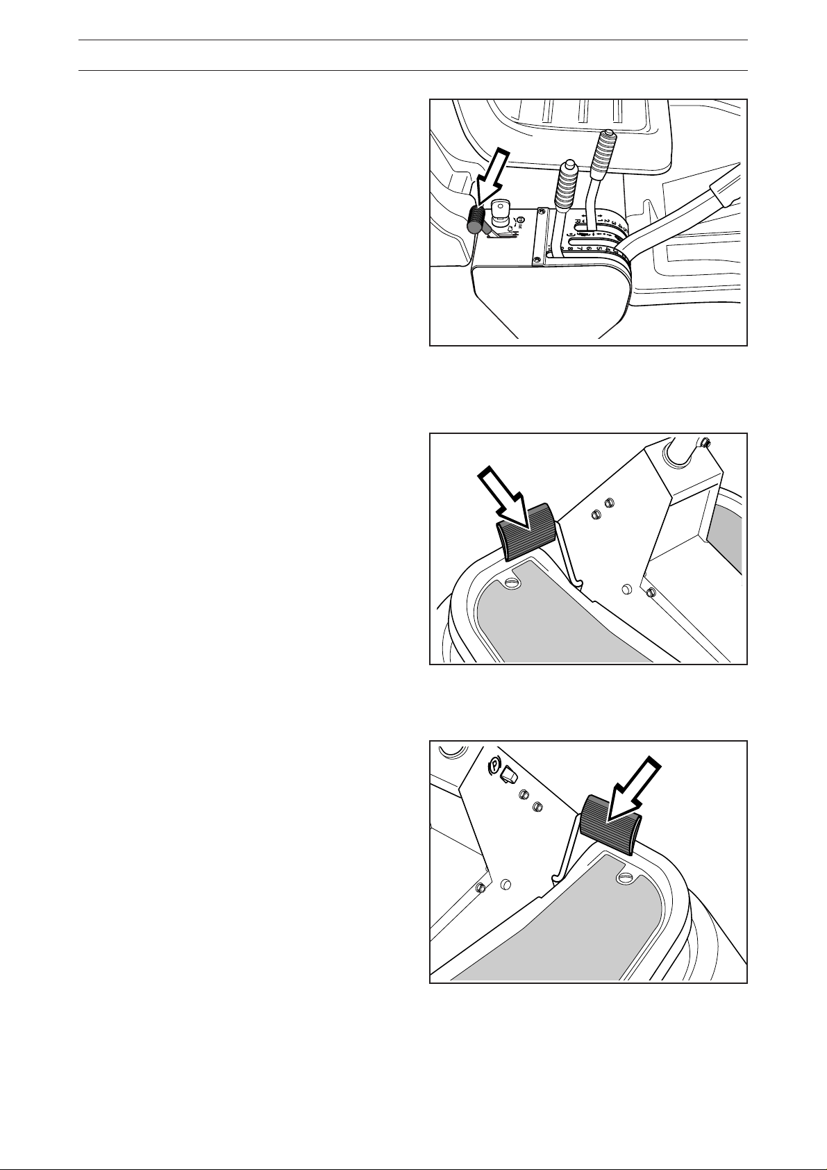
Parking brake
The parking brake is applied as follows:
1. Press down the brake pedal.
2. Press in the lock button on the steering column.
3. Release up the brake pedal while holding the
button pressed.
2
1
The lock on the parking brake automatically disconnects when the brake pedal is pressed.
English – 11
Page 13
PRESENTATION
Cutting unit
Rider 11 and Rider 13 have a cutting unit with rear
ejection, i.e. the grass cuttings are thrown out
behind the cutting unit.
Rider 11 Bio and Rider 13 Bio have a twin-blade
BioClip cutting unit.
Lift lever for cutting unit
The lift lever is used to set the cutting unit in transport or cutting position.
If the lever is pulled back the unit will lift up and the
blades will automatically stop rotating (transport
position).
If the lock button is pressed and the lever is moved
forward the unit will be lowered and the blades will
automatically start rotating (cutting position).
The lever can also be used to temporarily regulate
the cutting height, e.g. for a small mound in the lawn.
Lifting of the cutting unit (transport position)
12 – English
Lowering of the cutting unit (cutting position)
Page 14
PRESENTATION
Lever for adjustment of cutting height
With this lever the cutting height can be adjusted to
9 different positions.
Cutting unit with rear ejection, 40-90 mm.
BioClip cutting unit, 45-95 mm.
Seat
The seat has a jointed attachment on the front
edge and can be tipped forward.
The seat can also be adjusted lengthways.
Rider 13
Release the knobs under the seat and adjust it
forwards or backwards to the required position.
Lock the adjustment with the wheels.
Fuelling
The engine should be run on 85 octane (or higher)
unleaded petrol/gasoline (no added oil). Environmentally adapted alkylate fuel, such as Aspen, is
also recommended.
!
WARNING!
Petrol/gasoline is highly inflammable.
Observe care and fill up with fuel
outdoors (see safety instructions).
English – 13
Page 15
DRIVING
Before starting
• Read the safety instructions and information on
the location and function of the controls before
starting (see pages 5–13).
• Conduct daily maintenance before starting (see
maintenance schedule on page 19).
Adjust the seat to the required position.
Starting the engine
1. Lift up the cutting unit by pulling the lever back-
wards to locked position (transport position).
2. Apply the parking brake. This is done as follows:
• Press down the brake pedal (1).
• Press in the lock button on the steering
column (2).
• Release the brake pedal while the button is
held pressed.
The parking brake lock disconnects automatically when the brake pedal is pressed down.
On the Rider 11 and Rider 11 Bio the brake
pedal and lock button are on the right side.
3. For Rider 11 and Rider 11 Bio: Set the gear
lever to position “N” (neutral).
2
1
Rider 13
N
IMPORTANT INFORMATION
Do not press the reverse lock button on
the lever when you select neutral. If you
do, it could trigger the start lock.
14 – English
Rider 11
Page 16

Cold engine:
4. Push the throttle control to position 3 (choke
position). In this position the engine receives a
richer mixture so that the engine starts more
easily.
DRIVING
2
1
3
Warm engine:
5. Set the throttle control midway between position
1 and 2.
6. Turn the ignition key to start position.
2
1
3
IMPORTANT INFORMATION
Do not run the starter for more than about
5 seconds at a time. If the engine does not
start, wait about 10 seconds before trying
again.
STOP START
English – 15
Page 17

DRIVING
7. When the engine has started release the ignition
key to neutral position.
Push the throttle control to the required speed.
For cutting 3/4 to full throttle.
WARNING!
Never run the engine indoors, in
enclosed or poorly ventilated areas.
The exhaust fumes contain toxic
carbon monoxide.
Driving the machine
1. Release the parking brake by pressing down the
brake pedal.
STOP START
2. For Rider 13 and Rider 13 Bio
Carefully press down one of the pedals until the
correct speed is reached.
To drive forwards: press down pedal (1).
To reverse: press down pedal (2).
For Rider 11 and Rider 11 Bio
Press the clutch and engage the required gear.
To engage reverse gear the lock button must be
pressed down.
• Gears 1–4 are used for mowing.
• Gears 4–5 are used for transport.
Starting is possible irrespective of which gear is
engaged.
IMPORTANT INFORMATION
Do not change gear from forward drive to
reverse while the machine is moving.
The clutch must be used for each gear
change.
Stop the machine before changing for
forward drive to reverse, otherwise the
gearbox can be damaged.
Rider 13
Rider 13
2
1
N
Never
use force to engage a gear. If a gear
will not engage directly release and push
down the clutch again, and then try to
engage the gear again.
16 – English
Rider 11
Page 18

DRIVING
3. Select the required cutting height (1-9) with the
cutting height lever.
To obtain a uniform cutting height it is important
that the tyre pressures are equal on both front
wheels (60 kPa).
4. Push in the lock button on the lift lever and lower
down the cutting unit.
IMPORTANT INFORMATION
The service-life of the drive belts increases
considerably if the engine is run at low
speed when engaging the blades. For this
reason do not increase the throttle until
the cutting unit has been lowered to the
cutting position.
Cutting tips
• Localise and mark stones and other fixed objects
to avoid collision.
• Start with a high cutting height and reduce down
until the required cutting result are obtained.
• The cutting results are best with a high engine
speed (fast rotating blades) and low driving
speed (slow moving machine). If the grass is not
too high and thick the driving speed can be
increased or the engine speed reduced without
noticeably affecting the mowing results.
• The best lawns are achieved if the grass is cut
often. Mowing becomes more uniform and the
grass cuttings become more evenly distributed
over the surface. The total time consumption is
not greater since it is possible to select a higher
driving speed without inferior mowing results.
• Avoid mowing a wet lawn. The mowing results
are inferior since the wheels sink down into the
soft lawn.
• Hose down the cutting unit with water
underneath each time it is used. Put the cutting
unit in the service position first.
• If you use the BioClip unit it is important to mow
the grass regularly.
WARNING!
Clear the lawn from stones and
other object which can be thrown
out by the blades.
Mowing pattern
English – 17
Page 19

DRIVING
WARNING!
Never drive the machine on
ground with a slope of more than
15°. Mow slopes upwards and
downwards, never across. Avoid
sudden changes in direction.
Hill start, manual gearbox
1. Press down the parking brake.
2. Push the throttle control to 3/4 position to full
throttle position.
3. Push down the clutch and engage first gear.
4. Carefully release the clutch.
5. When the engine starts to pull, release the parking
brake.
Stopping the engine
Preferably allow the engine to idle for a minute to
obtain normal working temperature before stopping
it if it has been working hard.
MAX 15°
1. Lift up the cutting unit by pulling the lever back
to the end position.
2. Rider 11 and Rider 11 Bio: Pull back the
throttle control and put the gear lever into
neutral “N” without pressing the reverse lock
button. Turn the ignition key to the “STOP”
position.
Rider 13 and Rider 13 Bio: Pull back the
throttle lever and turn the ignition key to the
“STOP” position.
3. When the rider mower is stationary, hold down
the parking brake and push in the lock button.
STOP START
Release lever Rider 13 and Rider 13 Bio
In order to move the machine when the engine is
switched off the release lever must be pressed
down and forwards.
18 – English
Page 20

MAINTENANCE
Maintenance schedule
The following is a list of the maintenance which should be conducted on the machine. For the items which
are not described in these instructions go to an authorised service workshop.
Maintenance interval
in hours
Maintenance
Page
Daily
mainte-
nance
before start
Check the engine’s oil level 35 ●
Check the engine’s cooling air inlet 28 ●
Check the fuel pump’s air filter 26 ●
Check the steering wires 22 ●
Check the brakes 23 ●
Check the battery 26 ●
Check the safety system 27 ●
Check screws and nuts – ❍
Check for fuel and oil leakage – ❍
Change the engine oil
Clean the air filter’s pre-filter (foam plastic)
1)
2)
35 ●
25 ●
Check the cutting unit 29 ●
Check the tyre pressures (60 kPa) 28 ●
Lubricating the belt adjuster
Lubricate joints and shafts
3)
3)
36 ●
37 ●
Adjust the brakes – Rider 11 and Rider 11 Bio 23 ●
Check the V-belts – ❍
Check the transmission’s cooling flanges –– ❍
Rider 13 and Rider 13 Bio
Check the transmission’s oil level – Rider 13 and 36 ●
Rider 13 Bio
Adjust the brakes – Rider 13 and Rider 13 Bio 23 ●
Check and adjust the throttle wire 24 ●
Clean the cooling flanges on the engine and – ❍
transmission
2,4)
5025
100
Replace the air filter’s pre-filter and paper filter
2)
25 ●
Replace the fuel filter 24 ●
Replace the plug – ❍
1)
First change after 5 hours. 2) During dusty conditions cleaning and replacement should be more frequent.
machine lubrication should be conducted twice a week.
4)
Conducted by authorised service workshop.
3)
For daily use of the
● = Described in these instructions.
❍ = Not described in these instructions.
WARNING!
No service procedures must be conducted on the engine or cutting unit unless:
• The engine is switched off.
• The ignition key is removed.
• The parking brake is applied.
• The cutting unit is disengaged.
• The ignition cable is removed from the plug.
English – 19
Page 21

MAINTENANCE
Dismantling of the machine hoods
Engine hood
The engine is accessible for servicing when the
engine hood is lifted up.
Tilt the seat forward, release the rubber strap under
the seat, and tilt the hood backwards.
Front hood Rider 11 and Rider 13
Release the screws in the front hood (3) and lift off
the hood.
Front hood Rider 11 Bio and Rider 13 Bio
Release the catch and lift off the hood.
20 – English
Page 22

MAINTENANCE
Right-hand fender
Remove the screws (2 and 3) from the fender. On
the Rider 13 and Rider 13 Bio the knob (1) must
also be removed.
3
Left-hand fender
Release the screws in the fender and lift off the
fender.
11
1
2
English – 21
Page 23

MAINTENANCE
Checking and adjustment of the
steering wires
The steering is controlled by means of wires.
These can in time become slack, which implies that
the adjustment of the steering becomes altered.
Check and adjust the steering as follows:
1. Dismantle the frame-plate by releasing the
screws (two on each side).
2. Check the tension of the steering wires by
pushing them together as shown in the diagram.
It should be possible to push them together so
that the distance between them is half as much,
without using unnecessary force.
3. When necessary the wires can be tensioned by
tightening the adjusting nuts, one on each side
of the steering rim.
Do not tension the wires too tightly, they should
only be
Check the wire tension on completion of the
adjustment as per item 2.
22 – English
tightened
up to the steering rim.
Page 24

MAINTENANCE
Checking the brake Rider 11 and Rider
11 Bio
The brake is of the disc brake type and is fitted on
the gearbox.
Check that the brake is correctly adjusted by
measuring the distance between the brake lever
and the front edge of the recess on the chassis.
The distance should be 0–1 mm when the brake is
not applied.
Adjusting the brake Rider 11 and Rider
11 Bio
1. Release the lock nuts (1).
2. Tension the wire with the adjusting screw (2) so
that the distance between the brake lever and
the front edge of the recess on the chassis is
1 mm.
3. Tighten the lock nuts (1) after adjustment.
Check and adjust the brakes on Rider
13 and Rider 13 Bio
Check that the brakes are correctly adjusted by
placing the rider mower on a shallow downhill slope
and applying the brake.
If the rider mower begins to move then the brakes
must be adjusted.
The brake is adjusted as follows:
1. Release the lock nuts (1).
2
1
1
2
1
1
2. Tension the wire with the adjusting screw (2)
until all the play in the wire is taken up.
3. Tighten the lock nuts (1).
4. On completion of the adjustment the brake
should be re-checked.
WARNING!
Poorly adjusted brakes can result
in reduced braking power.
English – 23
Page 25

MAINTENANCE
Checking and adjustment of the
throttle wire
If the engine does not respond as it should when
the throttle lever is moved, or if it produces black
smoke or does not reach top speed, the throttle
wire may need adjusting.
1. Release the clamping screw (see arrow) and
push the throttle control to the choke position.
2. Pull the throttle wire’s outer casing to the far
right and check that the choke is fully activated.
3. Tighten the clamping screw.
4. Pull the throttle control back to the full throttle
position and check that the choke is no longer
activated.
Replacement of the fuel filter
Replace the pipe fitted fuel filter every 100 running
hours (once per season) or more frequently if it is
clogged.
Replace the filter as follows:
1. Raise the engine cover as described on page
20.
2. Move the hose clips away from the filter. Use a
pair of flat pliers.
3. Pull off the filter from the hose ends.
4. Press in the new filter on the hose ends. If
necessary soap solution can be applied on the
filter ends to simplify fitting.
5. Push the hose clips back on the filter.
24 – English
Page 26

MAINTENANCE
Replacing the air filter
If the engine seems to lack power or goes irregularly the reason may be that the air filter is clogged.
It is therefore important to replace the air filter at
regular intervals (see maintenance schedule on
page 19 for correct service interval).
The air filter is replaced as follows:
1. Raise the engine cover as described on page
20.
2. Remove the air filter housing’s plastic cover by
releasing the wing-nut.
3. Remove the wing-nut on the air filter and lift off
the paper filter with pre-filter.
4. Pull off the foam plastic pre-filter from the paper
filter and wash clean in mild detergent.
Squeeze it dry in a clean cloth.
Drench it with new engine oil. Wrap the filter in
an absorbent cloth and squeeze out excess oil.
Replace the paper filter if it is clogged with dirt.
IMPORTANT INFORMATION
Do not use compressed air to clean the
paper filter.
5. Fit the air filter as follows:
Push the pre-filter over the paper filter.
Fit the paper filter with pre-filter in the air filter
housing and tighten the wing-nut.
Replace the plastic cover oven the air filter
housing and tighten the wing-nut.
English – 25
Page 27

MAINTENANCE
Checking of the fuel pump’s air filter
Check regularly that the fuel pump’s air filter is free
from dirt.
The filter can when necessary be cleaned with a
brush.
Check the level of the battery acid
Check that the level of the battery acid lies between
only
the markings. Top up the cells with
water.
distilled
WARNING!
Procedures on contact with acid
External: Rinse well with plenty of water.
Internal: Drink large quantities of water or
milk. Contact a doctor as soon as
possible.
Eyes: Rinse well with plenty of water.
Contact a doctor as soon as possible.
Batteries emit explosive gas. Sparks, flames
and cigarettes must absolutely not be
brought into the vicinity of the battery.
26 – English
Page 28

Inspecting the safety system
N
MAINTENANCE
The Rider is equipped with a safety system that
prevents starting or driving under the following
conditions:
The engine should only be possible to start when
the cutting unit is in its raised position and the
hydrostat pedals are in the neutral position.
The driver does not need to be seated in the
driver’s seat.
Make daily inspections to ensure that the safety
system works by attempting to start the engine
when one of the conditions is not met. Change the
conditions and try again.
Check that the engine stops if you temporarily
move out off the driver’s seat while the cutting unit
is lowered or the hydrostat pedals are not in the
neutral position.
Startmotor
Ignition system
Works
Does not work
Rider 11
Rider 13
English – 27
Page 29

MAINTENANCE
RIDER 850
Checking the tyre pressure
The tyre pressure should be 60 kPa (0.6 kp/cm2) all
round.
To improve driving the pressure on the rear tyres
can be reduced to 40 kPa (0.4 kp/cm2).
The maximum tyre pressure is 100 kPa (1.0 kp/cm
IMPORTANT INFORMATION
Different tyre pressures on the front tyres
will result in the blades cutting the grass
at different heights.
2
).
Check the engine’s cooling air intake
Raise the engine cover as described on page 18.
Check that the cooling intake is free from leaves,
grass and dirt.
If the cooling intake is blocked this will interfere with
the cooling of the engine, which can damage the
engine.
28 – English
Page 30

MAINTENANCE
Checking and adjustment of the cutting
unit’s ground pressure on Rider 11 Bio
and Rider 13 Bio
To achieve the best cutting results the cutting unit
should follow the underlying surface without pressing too hard against it.
The pressure is adjusted with a screw on each side
of the machine.
1. Check the tyre air pressure. It should be 60 kPa
(0,6 kp/cm
2. Place a set of bathroom scales under the cutting
unit’s frame (front edge) so that it rests on the
scales. If necessary a block can be placed
between the frame and scales so that the
support wheels do not bear any weight.
3. Adjust the unit’s ground pressure by screwing in
or out the adjusting screws located behind the
front wheels on both sides.
The ground pressure should be between 12 and
15 kg.
2
).
Checking the cutting unit’s parallelism
Check the parallelism of the cutting unit as follows:
1. Check the tyre air pressure. It should be 60 kPa
(0,6 kp/cm
2. Place the machine on a level surface.
3. Measure the distance between the ground and
the front and rear edges of the cutting unit hood.
The cutting unit should slope forwards slightly so
that the rear edge is 2-4 mm higher than the
front edge.
2
).
English – 29
Page 31

MAINTENANCE
Adjustment of the cutting unit’s
parallelism for the Rider 11 Bio and
Rider 13 Bio
1. Check the tyre air pressure. It should be 60 kPa
(0,6 kp/cm
2. Dismantle the front hood and right-hand fender
as described on page 20-21.
3. Vertical adjustment of the cutting unit is made
with the adjusting nuts on the back edge of the
lift-strut.
4. Raise the cutting unit at the front edge by
shortening the lift-strut.
Lower the cutting unit at the front edge by
lengthening the lift-strut.
5. Tighten the nuts against each other after the
adjustment.
6. On completion of the adjustment the unit’s
parallelism should be re-checked.
Fit the right-hand fender and the front hood.
2
).
2
Adjusting the alignment of the cutting
unit for the Rider 11 Bio and Rider 13
Bio
1. Check the tyre air pressure. It should be 60 kPa
(0,6 kp/cm
2. Remove the front hood and right-hand fender as
described on page 20-21.
3. Unscrew the nut (1) from the parallel strut.
Remove the clip (2) and the parallel strut.
4. Turn the fork anti-clockwise to lower the rear
edge of the hood, or clockwise to raise the rear
edge of the hood.
5. Once adjustment is complete, refit the parallel
strut and clip and tighten the nut.
6. Recheck the alignment of the cutting unit after
adjustment.
7. Refit the right-hand fender and hood.
2
).
30 – English
Page 32

MAINTENANCE RIDER 11 BIO/13 BIO
P
1
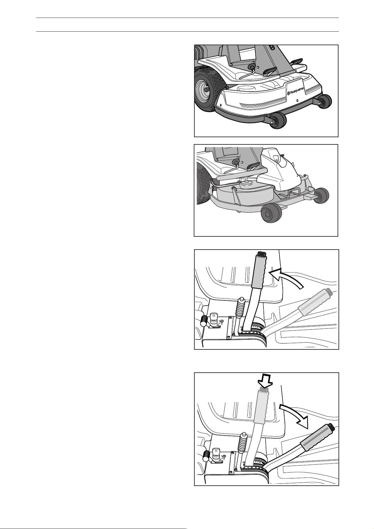
Service position for BioClip 90
The cutting head can be placed in the service
position to provide easy access for cleaning, repairs
and servicing. In the service position the cutting unit
is raised and locked in the vertical position.
Placing in service position
1. Position the machine on flat ground. Apply the
parking brake (1), see page 10. Adjust the
cutting unit to the lowest cutting height and
lower the cutting unit.
2. Remove the front hood by removing the pin.
(There are complete instructions on using the
service position inside the front hood).
3. Remove the two support wheels from under the
front hood.
English – 31
Page 33

MAINTENANCE RIDER 11 BIO/13 BIO
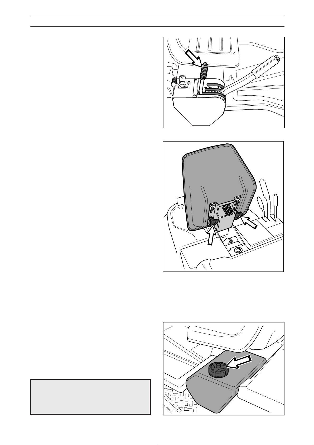
4. Fit the support wheels on either side of the rear
of the cutting unit.
WARNING!
Wear protective glasses when
dismantling the cutting unit. The
spring which tensions up the belt
can go off and cause personal
injury.
5. Disengage the spring from the drive belt
tensioning wheel.
6. Move the cutting height lever to the lower
position.
7. Place a foot on the front edge of the cutting unit
near the wheel and raise the front edge of the
unit to make it easier to remove the lift strut.
Engage the strut in the holder.
32 – English
Page 34

MAINTENANCE RIDER 11 BIO/13 BIO
2
1
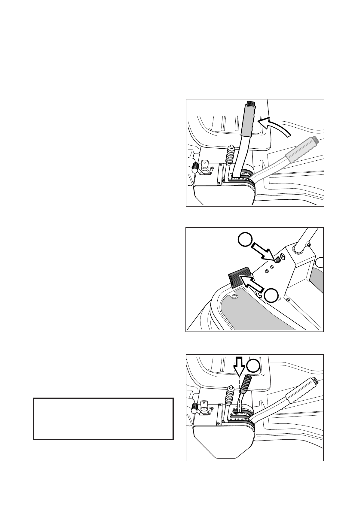
8. Lift off the drive belt (1). Then pull out the pin
(2).
Take care not to get your hand trapped.
9. Pull the frame forwards and refit the pin.
10. Grasp the front edge of the cutting unit, pull out
and raise into the service position.
If the cylindrical bolt, which is now holding the
cutting unit is removed, the cutting unit can be
lifted off.
Restoring from service position
To leave the service position, reverse the
procedures set out in “Placing in the service
position”. Make sure that the cutting unit’s ”lug”
enters the loop correctly on the underside of the
machine, see diagram.
English – 33
Page 35

MAINTENANCE
Checking the blades
To achieve the best mowing results it is important
that the blades are undamaged and well-sharpened.
Check that the blades’ attachment screws are tight.
IMPORTANT INFORMATION
Replacing or sharpening the blades
should be conducted by an authorised
service workshop.
The blades should be balanced after sharpening.
Damaged blades should be replaced when hitting
obstacles that result in a breakdown. Let the
servicing dealer judge whether the blade can be
repaired/ground or must be discarded.
IMPORTANT INFORMATION
The blades of the BioClip unit should
always be spaced as shown in the diagram at 90º intervals. If not, the blades
may collide and cause damage to the
cutting unit.
Replacing the break-pin (BioClip)
The blades are fitted with a break-pin to protect the
BioClip unit and its drive when colliding with
obstacles. A domed, spring friction washer is fitted to
each blade bolt. The washer must always be
replaced with a new washer if the blade bolt is
loosened. Otherwise the break-pin can break causing
the blades to collide.
Only use original spare parts. A set containing a
blade, break-pin and friction washer can be
purchased from your dealer.
Cutting unit (rear ejection)
Bio 90
1. Put the unit in the service position, see “Placing
in the service position”.
2. Remove the blade (2A) by removing the blade
bolt with washer and friction washer (2B).
3. Remove the remains of the broken break-pin (3).
4. Make sure the contact surfaces (4) on the blade
and the blade mounting are free from metal.
Clean if necessary.
5. Fit one new break-pin (5) in the blade mounting.
6. Fit the blade (6), make sure it is fitted as
illustrated.
7. Fit a new friction washer (7) with the concave
face turned towards the blade.
8. Fit the blade bolt with washer (8). Tightening
torque 45-50 Nm (4,5-5 kpm)
34 – English
2A
2B
5
3
4
6
4
7
8
Page 36

LUBRICATION
Check the engine’s oil level
Check the oil level in the engine when the machine
is horizontal.
Raise the engine cover as described on page 18.
Release the dip stick and pull out. Wipe off the oil
and insert again.
The dip stick must be fully screwed down.
Now release the dip stick again and pull out. Check
the oil level.
The oil level should lie between the markings on dip
stick. If the level approaches the “ADD” mark, top
up with oil to the “FULL” mark.
The oil is filled in the same hole for the dip stick
Use engine oil SAE 30 or SAE 10W/30, class SF-CC.
The total oil volume in the engine is 1.4 litres.
Changing the oil
The oil should be changed for the first time after
5 hours of running time. Thereafter it should be
changed every 25 hours of running time.
WARNING!
Engine oil can be very hot if it is
drained off directly after the
engine is stopped. Therefore
allow the engine to cool down
first.
1. Place a receptacle under the engine’s drain
plug, located on the left-hand side of the engine.
ADD
ADD
FULL
FULL
2. Remove the dip stick and drain plug.
3. Let the oil run out into the receptacle.
4. Fit the drain plug and tighten.
5. Fill up with oil to the “FULL” mark on the dip
stick. The oil is filled in the same hole for the dip
stick.
Use engine oil SAE 30 or SAE 10W/30, class
SF-CC.
Use engine oil with min. API SF quality and SAE
30 or SAE 10W/30 viscosity grade. The oil
volume in the engine is 1.4 litres.
6. Run the engine warm and then check that there
is no leakage from the drain plug.
IMPORTANT INFORMATION
Used engine oil is hazardous to health and
environment and must in accordance with
the law not be poured out on the ground
or in the nature, and must be handed in to
a workshop or other designated station for
treatment. Avoid skin contact, wash with
soap and water in the event of spillage.
English – 35
Page 37

LUBRICATION
Check the transmission’s oil level
Rider 13 and Rider 13 Bio
1. Lift off the transmission cover. Release the two
screws (one of each side) and lift off the transmission cover.
2. Check that there is oil in the transmission oil
tank. Top up if necessary with engine oil SAE
10W/30 (class SF–CC).
Lubrication of belt tensioner
The belt tensioner must be lubricated regularly with
high-quality molybdenum sulphide grease*.
Inject grease into the nipple on the right side below
the engine bottom pulley until grease is forced out.
With daily use lubrication should be conducted
twice a week.
General lubrication
All joints and bearings are lubricated on manufacture with molybdenum sulphide grease. Re-grease
with same type of grease*. Lubricate the steering
and control wires with engine oil.
The machine should be lubricated regularly, and
twice a week when used daily.
* Grease from well-known brand names (petrol
companies, etc.) usually maintains a good quality.
The most important property is that the grease
provides good protection against corrosion.
36 – English
Page 38

LUBRICATION
Lubrication Rider 11 and Rider 11 Bio
Lubrication of front wheel bearings
On Riders with rear ejection the hood and wings
must be removed so that the bar can be raised to
allow removal of the wheel.
1. Remove the plastic cover on the hub.
2. Remove the lock-ring and washer on the front
wheel axle.
3. Lift off the wheel.
4. Grease the axle journal with molybdenum
sulphide grease*.
5. Assemble the parts in the reverse order.
IMPORTANT INFORMATION
Check that the lock-ring is correctly posi-
tioned in the slot.
* Grease from well-known brand names (petrol
companies, etc.) usually maintains a good quality.
The most important property is that the grease
provides good protection against corrosion.
English – 37
Page 39

TROUBLE SHOOTING SCHEDULE
Problem Procedure
Engine will not start. • Fuel tank empty.
• Plug defective.
• Plug connection defective.
• Dirt in carburettor or fuel pipe.
Starter does not pull round engine. • Battery flat.
• Bad contact between cable and battery terminal.
• Lift lever for cutting unit in wrong position.
• Main fuse blown. The fuse is placed in front of the
battery, under the battery cover.
• Ignition lock faulty.
• Gear shift/hydrostat pedal not in neutral.
Engine does not run smoothly. • Wrong gear, too high.
• Carburettor incorrectly set.
• Air filter clogged.
• Fuel tank vent blocked.
• Ignition setting defective.
• Dirt in fuel pipe.
• Choke activated or throttle wire incorrectly adjusted
Engine seems to have no power. • Air filter clogged.
• Plug defective.
• Dirt in carburettor or fuel pipe.
• Carburettor incorrectly set.
• Choke activated or throttle wire incorrectly adjusted
Engine overheats. • Engine overloaded.
• Air intake or cooling flanges blocked.
• Fan damaged.
• Too little or no oil in engine.
• Ignition defective.
• Plug defective.
Battery does not charge. • One or more cells faulty.
• Bad contact between battery terminals and cables.
Machine vibrates. • Blades are loose.
• Engine is loose.
• Imbalance on one or more blades, resulting from
damage or inferior balancing after sharpening.
Uneven mowing. • Blades blunt.
• Cutting unit skew.
• Long or wet grass.
• Grass blockage under hood.
• Different tyre pressures on right and left sides.
• Over-speeding.
• Drive belts slipping.
• The blade has a broken break-pin (BioClip)
38 – English
Page 40

STORAGE
Winter storage
At the end of the season the machine should
immediately be put in order for storage, also if it is
going to stand idle for more than 30 days. Fuel
which is left to stand for long periods (30 days or
more) can leave tacky deposits which can block
the carburettor and interfere with the engine.
Fuel stabiliser is an acceptable alternative to avoid
tacky deposits during storage. If alkylate petrol
(Aspen) is used stabiliser is not necessary since
this fuel is stable. However, one should avoid
changing from standard to alkylate petrol since
sensitive rubber parts can harden. Add stabiliser to
the fuel in the tank or the storage container. Always
use the mixing ratios indicated by the manufacturer.
Run the engine for at least 10 minutes after adding
the stabiliser so that it will reach the carburettor. Do
not empty the fuel tank and carburettor if stabiliser
has been added.
To put the machine in order for storage follow these
instructions:
1. Carefully clean the machine, especially under
the cutting unit. Touch-up paint damage to avoid
rust.
2. Inspect the machine for worn or damaged parts
and tighten loose screws and nuts.
3. Change the oil, and take care of the waste oil.
4. Empty the fuel tank. Start the engine and run it
until the carburettor is emptied of fuel.
5. Remove the spark plug and pour about a tablespoon of engine oil into the cylinder. Pull round
the engine to distribute the oil and screw the
plug back on.
6. Grease all grease nipples, joints and axles.
7. Remove the battery. Clean it, charge it, and
store it is a cool place.
8. Store the machine is a clean and dry place and
cover it over for extra protection.
!
WARNING!
Never place an engine with fuel in
the tank indoors or in poorly
ventilated areas where petrol fumes
can come into contact with naked
flames, sparks or pilot flames in
boilers, hot water heaters, or
drying cabinets, etc. It is highly
inflammable and negligent usage
can cause severe person injury
and material damage. Drain off
the fuel in an approved container
outdoors and well clear of naked
flames. Never use petrol for cleaning
purposes. Use degreasing agents
and hot water instead.
Service
When ordering spare parts state the purchase year,
model, type, and serial number.
Always use genuine parts.
Annual inspection or trimming by an authorised
service workshop is a good way of getting the best
out of your machine the next season.
English – 39
Page 41

TECHNICAL DATA
Dimensions Rider 11 Rider 13
Length 2000 mm 2000 mm
Width 960 mm 960 mm
Height 1060 mm 1060 mm
Unladen weight 225 kg 225 kg
Wheel base 820 mm 820 mm
Track 610 mm 625 mm
Tyre size 16 x 6.50 x 8 16 x 6.50 x 8
Tyre pressure, front & rear 60 kPa (0.6 kp/cm
Max. gradient 15° 15°
Engine
Manufacture Briggs & Stratton model 28B707 Briggs & Stratton model 28N707
Power 7.7/10.5 kW/h.p. 9.2/12.5 kW/h.p.
Displacement 465 cm
3
Fuel minimum 85 octane unleaded minimum 85 octane unleaded
Tank volume 7 litres 7 litres
Oil SAE 30 or SAE 10W/30 SAE 30 or SAE 10W/30
class SF-CC class SF-CC
Oil volume 1.4 litres 1.4 litres
Start Electric starter Electric starter
2
) 60 kPa (0.6 kp/cm2)
465 cm
3
Electrical system
Type 12 V, negative earth 12 V, negative earth
Battery 12 V, 24 Ah 12 V, 24 Ah
Spark plug Champion CJ8 or J8 Champion CJ8 or J8
electrode gap = 0.7–0.8 mm electrode gap = 0.7–0.8 mm
Transmission
Manufacture Peerless typ MST 205 Tuff Torq K46
Oil SAE 10W/30, class SF-CC
No. of forward gears 5
No. of reverse gears 1
Speed in forward gears 1.85-8.9 km/h 0-9 km/h
Speed in reverse 2.5 km/h 0-6 km/h
Cutting unit
Type 3-blade unit with rear ejection 3-blade unit with rear ejection
Cutting width 850 mm 850 mm
Cutting height 9 pos. 40–90 mm 9 pos. 40–90 mm
Blade diameter 304 mm 304 mm
NOISE LEVEL 100 dB(A) 100 dB(A)
We reserve the right to change technical specifications without prior notice.
Note that no legal claims are valid on the basis of information in this manual.
Use only genuine parts for repairs. The warranty is not valid if non genuine parts are used.
40 – English
Page 42

TECHNICAL DATA
Dimensions Rider 11 Bio Rider 13 Bio
Length without cutting unit 2145 mm 2145 mm
Width without cutting unit 1050 mm 1050 mm
Height 1060 mm 1060 mm
Unladen weight 245 kg including cutting unit 245 kg including cutting unit
Wheel base 855 mm 855 mm
Track front 715 mm715 mm
rear 625 mm625 mm
Tyre size 16 x 6,50 x 8 16 x 6,50 x 8
Tyre pressure, front & rear 60 kPa (0,6 kp/cm
Max. gradient 15° 15°
Engine
Manufacture Briggs & Stratton model 28B707 Briggs & Stratton model 28N707
Power 7,7/10,5 kW/h.p. 9,2/12,5 kW/h.p.
Displacement 465 cm
3
Fuel minimum 85 octane unleaded minimum 85 octane unleaded
Tank volume 7 litres 7 litres
Oil SAE 30 or SAE 10W/30 SAE 30 or SAE 10W/30
class SF-CC class SF-CC
Oil volume 1,4 litres 1,4 litres
Start Electric starter Electric starter
2
) 60 kPa (0,6 kp/cm2)
465 cm
3
Electrical system
Type 12 V, negative earth 12 V, negative earth
Battery 12 V, 24 Ah 12 V, 24 Ah
Spark plug Champion CJ8 or J8 Champion CJ8 or J8
electrode gap = 0,7–0,8 mm electrode gap = 0,7–0,8 mm
Transmission
Manufacture Peerless typ MST 205 Tuff Torq K46
Oil SAE 10W/30, class SF-CC
No. of forward gears 5
No. of reverse gears 1
Speed in forward gears 1,85-8,9 km/h 0-9 km/h
Speed in reverse 2,5 km/h 0-6 km/h
Cutting unit
Type 2-blade unit BioClip 900 mm 2-blade unit BioClip 900 mm
Cutting width 900 mm 900 mm
Cutting height 9 pos. 45–95 mm 9 pos. 45–95 mm
Blade diameter 410 mm 410 mm
NOISE LEVEL 100 dB(A) 100 dB(A)
When this product is worn out or no longer used it should be returned to
the dealer or other appropriate body for recycling.
English – 41
Page 43

EU declaration of conformity (Only applies to Europe)
(Directive 89/392/EEC, Annex II, A)
We, Husqvarna AB, S-561 82 Huskvarna, Sweden, tel. +46 36-146500, declare under sole responsibility that the
rider mowers Husqvarna Rider 11/13 and Rider 11 Bio/13 Bio from 1998’s serial numbers and onwards (the year
is clearly stated in plain text on the type plate with subsequent serial number), is in conformity with the following
standards or other normative documents following the provisions in the COUNCIL’S DIRECTIVES:
- of June 14 1989 “relating to machinery” 89/392/EEC, and applicable supplements.
- of March 22 1984 “relating to permitted sound power levels for lawn mowers” 84/538/EEC, and applicable supplements.
- of May 3 1989 “relating to electromagnetic compatibility” 89/336/EEC, and applicable supplements.
The following standards have been applied: EN292-2, EN836.
Huskvarna October 16, 1998
Roger Andersson, Development manager
42 – English
Page 44

SERVICEJOURNAL RIDER 11/13
Work done
Pre-delivery service
1. Top up battery with acid and recharge for four hours.
2. Fit steering wheel, seat and any optional equipment.
3. Adjust cutting unit:
Adjust the lifting springs (the “weight” of the cutting unit should
be 12-15 kg). Only applies to BioClip.
Adjust cutting unit so that rear edge is about 2–4 mm higher
than front edge.
Adjust cutting unit height setting so that cutting height limit is 5
mm above the frame of the unit at the lowest cutting height.
4. Check that engine has correct amount of oil.
5. Check that the right amount of oil is in the transmission. (Not
Rider 11)
6. Check and adjust tyre pressure (60 kPa, 0.6 bar).
7. Connect battery.
8. Fill with fuel and start engine.
Date, mileage, stamp, sign
9. Check that machine does not move in neutral. (Not Rider 11)
10. Check:
Forward drive.
Reverse drive.
Operation of blades.
Seat safety switch.
Lift lever safety switch.
Safety switch for hydrostatic pedals/neutral setting.
11. Check engine revs 2 950 rpm.
12. Tell customer about:
Need and benefits of following the service schedule.
The need and advantages of leaving the machine for regular
service.
The effects of maintenance on the machine’s second hand
value.
Pre-delivery service carried out.
No outstanding problems.
Certified:
Range of applications for BioClip.
13. Complete proof of sale, etc.
After first 5 hours
1. Change engine oil.
English – 43
Page 45

SERVICEJOURNAL
Work done
○○○○○○○○○○○○○○○○○○○○○○○○○○○○○○○○○○○○○○○○○○○○○○○○○○○○○○○○○○○○
○○○○○○○○○○○○○○○○○○○○○○○○○○○○○○○○○○○○○○○○○○○○○○○○○○○○○○○○○○○○
○○○○○○○○○○○○○○○○○○○○○○○○○○○○○○○○○○○○○○○○○○○○○○○○○○○○○○○○○○○○○○○○○○○○○○○○○○○○○○○○○○○○○○○○○○○○○○○○○○○○○○○○○○○○○○○○○○○○○○○○
○○○○○○○○○○○○○○○○○○○○○○○○○○○○○○○○○○○○○○○○○○○○○○○○○○○○○○○○○○○○
○○○○○○○○○○○○○○○○○○○○○○○○○○○○○○○○○○○○○○○○○○○○○○○○○○○○○○○○○○○○
○○○○○○○○○○○○○○○○○○○○○○○○○○○○○○○○○○○○○○○○○○○○○○○○○○○○○○○○○○○○
○○○○○○○○○○○○○○○○○○○○○○○○○○○○○○○○○○○○○○○○○○○○○○○○○○○○○○○○○○○○
○○○○○○○○○○○○○○○○○○○○○○○○○○○○○○○○○○○○○○○○○○○○○○○○○○○○○○○○○○○○
○○○○○○○○○○○○○○○○○○○○○○○○○○○○○○○○○○○○○○○○○○○○○○○○○○○○○○○○○○○○
○○○○○○○○○○○○○○○○○○○○○○○○○○○○○○○○○○○○○○○○○○○○○○○○○○○○○○○○○○○○
Date, mileage, stamp, sign
○○○○○○○○○○○○○○○○○○○○○○○○○○○○○○○○○○○○○○○○○○○○○○○○○○○○○○○○○○○○
○○○○○○○○○○○○○○○○○○○○○○○○○○○○○○○○○○○○○○○○○○○○○○○○○○○○○○○○○○○○
○○○○○○○○○○○○○○○○○○○○○○○○○○○○○○○○○○○○○○○○○○○○○○○○○○○○○○○○○○○○
○○○○○○○○○○○○○○○○○○○○○○○○○○○○○○○○○○○○○○○○○○○○○○○○○○○○○○○○○○○○
○○○○○○○○○○○○○○○○○○○○○○○○○○○○○○○○○○○○○○○○○○○○○○○○○○○○○○○○○○○○
○○○○○○○○○○○○○○○○○○○○○○○○○○○○○○○○○○○○○○○○○○○○○○○○○○○○○○○○○○○○
○○○○○○○○○○○○○○○○○○○○○○○○○○○○○○○○○○○○○○○○○○○○○○○○○○○○○○○○○○○○
○○○○○○○○○○○○○○○○○○○○○○○○○○○○○○○○○○○○○○○○○○○○○○○○○○○○○○○○○○○○
○○○○○○○○○○○○○○○○○○○○○○○○○○○○○○○○○○○○○○○○○○○○○○○○○○○○○○○○○○○○
○○○○○○○○○○○○○○○○○○○○○○○○○○○○○○○○○○○○○○○○○○○○○○○○○○○○○○○○○○○○
○○○○○○○○○○○○○○○○○○○○○○○○○○○○○○○○○○○○○○○○○○○○○○○○○○○○○○○○○○○○
○○○○○○○○○○○○○○○○○○○○○○○○○○○○○○○○○○○○○○○○○○○○○○○○○○○○○○○○○○○○
○○○○○○○○○○○○○○○○○○○○○○○○○○○○○○○○○○○○○○○○○○○○○○○○○○○○○○○○○○○○
○○○○○○○○○○○○○○○○○○○○○○○○○○○○○○○○○○○○○○○○○○○○○○○○○○○○○○○○○○○○
44 – English
´*3/r¶69¨
Page 46

English – 45
Page 47

´*3/r¶69¨
2000W50
 Loading...