

Page 1
EN FR ES
Page 2
CONTENTS
Contents
Introduction 2...................
Key to symbols 3..................
Safety instructions 4...............
Description 6.....................
Fuel handling 11....................
Starting and stopping 12............
Using the blower 13.................
Maintenance 16....................
Technical data 19...................
Maintenance, replacement, or repair of the
emission control devices and system may
be performed by any nonroad engine repair establishment or individual.
The blo wer is used for blowing away leaves
and other debris on the ground. When operating the blower, the operator must stand
with both feet firmly on the ground.
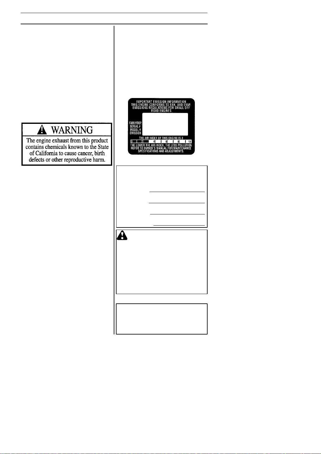
The Emissions Compliance Period referred
to on the Emissions Compliance label indicates the number of operating hours for
which the engine has been shown to meet
Federal emissions requirements.
Category C = 50 hours, B= 125 hours, and
A = 300 hours.
Note the following before
starting:
Husqvarna AB has a policy of continuous
product development and therefore
reserves the right to modify the design and
appearance of products without prior
notice. Long--term exposure to noise can
result in permanent hearing impairment.
Always use approved hearing protection.
This operator’s manual describes in detail
how to use and service the blower and
how to carry out regular maintenance. It
also describes which measures should be
taken to achieve maximum safety while
operating the blower, how the safety devices work and how they should be serviced.
Note! The section of the manual that deals
with safety, must be read and understood
by all persons who come in contact with
the blower.
This operator’s manual has been written
for those who need guidance when it
comes to fault tracing, thorough servicing
and carrying out corrective maintenance of
the blower.
There are warning symbols on the blower.
Should any of the warning symbols on the
blower become disfigured or worn, new ones
should be ordered and fitted to the blower as
soon as possible. Note that some of the
warning symbols may be molded in certain
components of the blower.
545154658 Rev. 2 7/10/07
For reference, please fill out the following
information that will be needed for future
servicing of your blower:
Model Number:
Serial Number:
Purchase Date:
Purchased From:
WARNING: Under no circum-
stances may the design of the
machine be modified without the
permission of the manufacturer.
Always use genuine accessories.
Non--authorized modifications
and/or accessories can result
in serious personal injury or the
death of the operator or others.
Your warranty may not cover
damage or liability caused by the
use of non--authorized accessories or replacement parts.
For customer assistance,call:
1-800-487-5951
Contact us at our website:
www.husqvarna.com
English--- 2
Page 3
KEY TO SYMBOLS
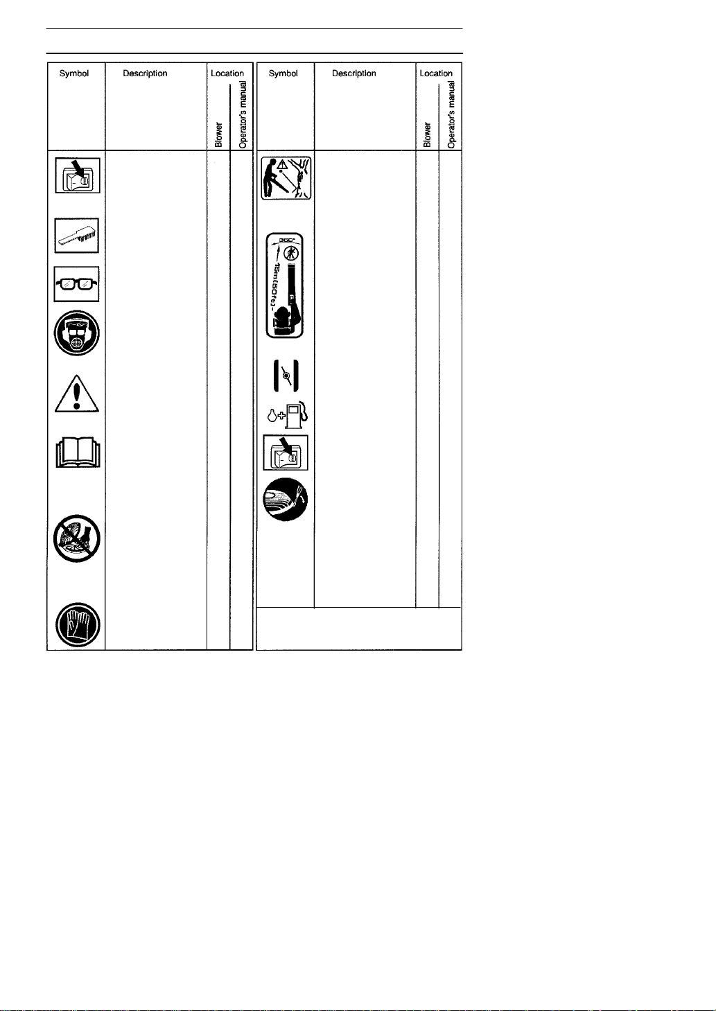
Checks and/or maintenance shall be
carried out after
having switched off
the engine and disconnected the spark plug.
Cleaning at regular
intervals is required.
Approved protective
goggles or visor must
be worn.
Approved protective
goggles or visor, ear
protection, and face
mask in dusty envir o nments must be worn.
WARNING! The blower can be dangerous!
Careless or improper
use can cause serious, even fatal injury.
Read the operator’s
manual carefully and
make sure that you
understand the
contents before using
the blower.
WARNING! Make sure
that the inlet cover is
locked in the closed
position or that the
vacuum tube is mounted on the blower. Never
touch the impeller unlesstheunitisoff,the
impeller has stopped
moving and the spark
plug is disconnected.
Always wear approved,
protective gloves.
X
X
X
XX
XX
XX
XX
XX
WARNING! The blower
may throw objects at
high velocity that can
ricoch et and hit the operator. This may cause
serious eye damage .
The blower operator
must make sure that
no bystanders or
animals come nearer
than 50 feet (15 meters).
Whenever several
operators are working
inthesameworkarea,
they should maintain a
safe distance of at
least 50 feet (15 meters) from one another.
Choke
Refueling
Stop switch
Instructions on how to
open the inlet cover.
Other symbols/decals on the machine
refer to special certification requirements
for certain markets.
XX
XX
X
X
X
X
545154658 Rev. 2 7/10/07
English--- 3
Page 4
SAFETY INSTRUCTIONS
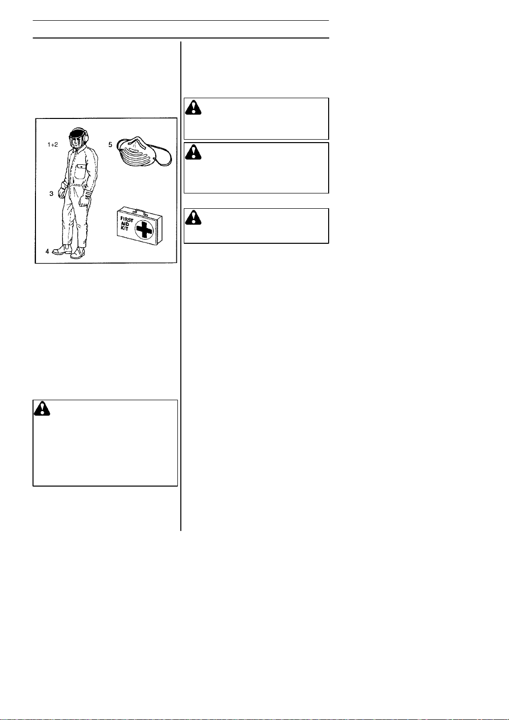
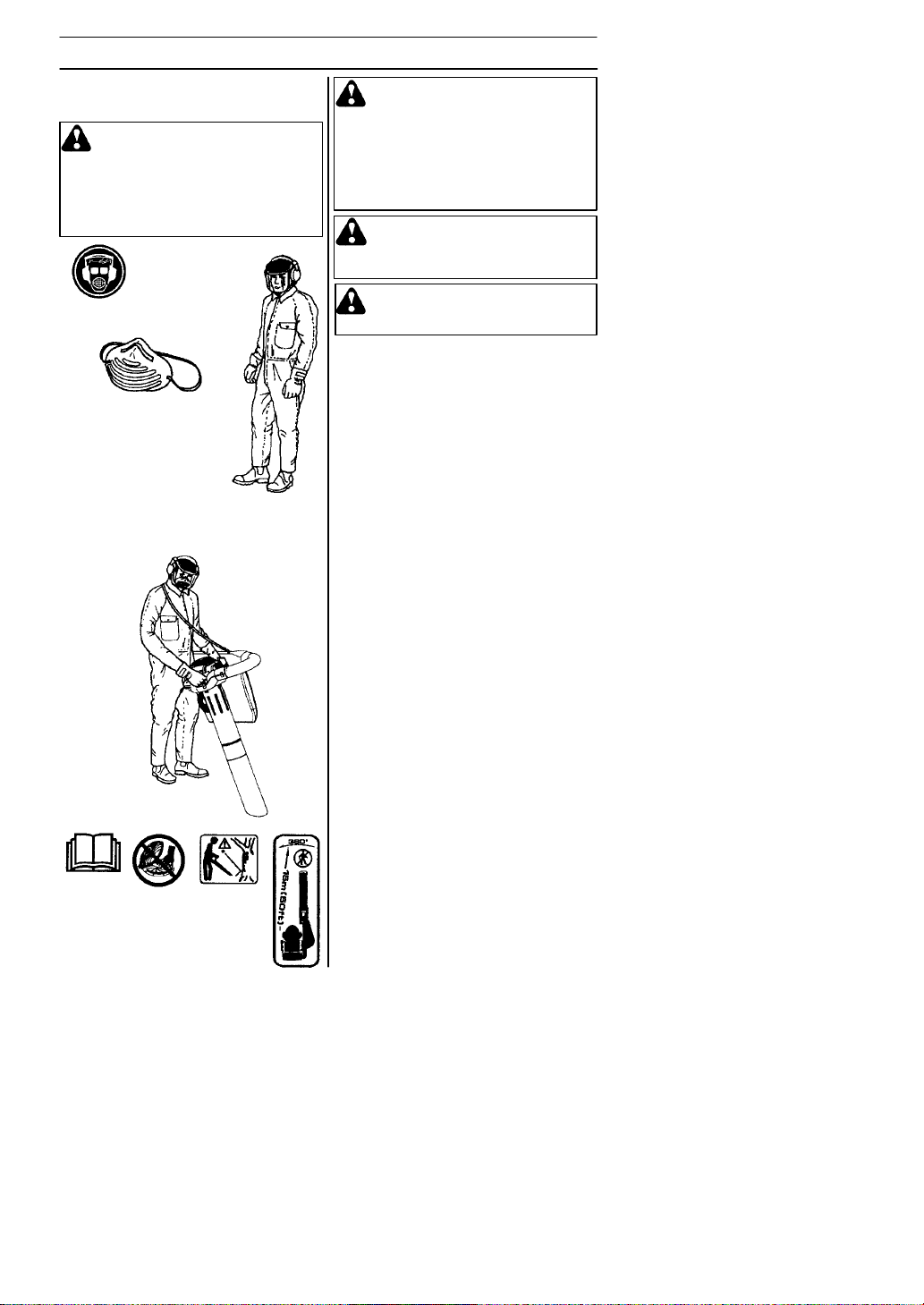
Personal safety equipment
Persons who use the blower shall wear the
following safety equipment:
1. Approved ear protection.
2. Approved eye protection.
3. Approved protective gloves.
4. Boots or work shoes with a non--slip sole.
5. Face mask when operating the blower in
dusty environments.
Personal safety
The following instructions apply to persons
operating the blower:
S The operator shall have read and under-
stood the contents of this manual.
S Do not wear loose clothing, scarves or
neckchains or let long hair hang loose,
since these can be drawn into rotating
parts of the blower and cause injury.
S Do not operate the blower while under
the influence of alcohol, drugs or when
you are tired.
S Do not allow minors to operate the
blower.
S Always have a first aid kit nearby.
Fuel safety
WARNING: The fuel used to run
the blower has the following
dangerous characteristics:
1. Volatile liquid: its vapor and
exhaust fumes are poisonous.
2. Direct contact can cause skin
irritation.
3. It is extremely flammable.
Special safety instructions apply to the type
of fuel used for the blower. These instructions are specified under the Fuel handling
section.
545154658 Rev. 2 7/10/07
Muffler
The muffler is designed to give the lowest
possible noise level and to direct the engine’s exhaust fumes away from the operator. Mufflers fitted with catalytic converters
are also designed to reduce harmful exhaust components.
WARNING: The exhaust fumes
from the engine are hot and may
contain sparks which can start a fire.
Never start the machine indoors or
near flammable material!
WARNING: Mufflers fitted with
catalytic converters become extremely hot during use and after stopping.
This also applies at idling speeds.
Contact can result in burns to the
skin.Beawareoftheriskoffire!
Safety equipment
WARNING: The blower must
never be used if any of the safety
devices or guards are missing,
damaged or not in working order.
The blower is equipped with a number of
safety devices and guards for the prevention of accidents. These are described in
the general description of the blower.
The safety devices and guards also require
regular inspection and maintenance. These
measures and the interval at which they
should be carried out are specified in the
Maintenance section.
Safety while operating the
blower
S Do not allow bystanders or animals to be
in the work area, i.e. 50 feet (15 meters)
from the operator.
S The blower may throw objects at high
velocity that can ricochet and hit the operator. This may cause serious eye damage.
S Never point the blower nozzle toward
people or animals.
S Stop the engine before fitting or disman-
tling accessories or other components.
S Never operate the blower if any of the
guards are missing.
S Never operate the blower in poorly venti-
lated spaces where exhaust fumes might
otherwise be inhaled.
S Stop the engine before refueling. Move
the unit at least 10 feet (3 meters) from
fueling site before attempting to start.
S The catalytic muffler is extremely hot
while the blower is running and after it
has stopped. The same applies when the
blower is running at idling speed. Be
aware of the danger of fire, especially
while operating the blower near flammable materials and/or where flammable
fumes are present.
English--- 4
Page 5

SAFETY INSTRUCTIONS
S Be careful, particularly ifleft hand opera-
tion is applied. Avoid any direct body contact with inlet cover area. Keep jewelry,
loose clothing, or clothing with loosely
hanging straps, ties, tassels, etc., away
from inlet cover area.
S Do not operate the blower while standing
on a ladder or a stand.
Other safety measures
S Operate the blower only at reasonable
hours, i.e. not early in the morning or late
at night when people might be disturbed.
Comply with times listed in local ordinances. Usual recommendations are 9:00
a.m. to 5:00 p.m., Monday through Saturday.
S Operate the blower at the lowest possible
throttle setting to do the job.
S Check the condition of the blower before
operation, especially the muffler, air intake
and air filter.
S Use a rake or a broom to loosen ground
debris before blowing.
S Under dusty conditions, slightly spray the
work area with a hose.
S Conserve water by using blowers instead
of hoses for many lawn and garden
applications, including areas such as roof
gutters, screens, patios and gardens etc.
S Watch out for children, pets, open windows
or vehicles, and blow debris safely away.
S Use the full nozzle extension so the air
stream can work close to the ground.
S After using the blower, clean up and
dispose of debris in trash receptacles.
545154658 Rev. 2 7/10/07
English--- 5
Page 6
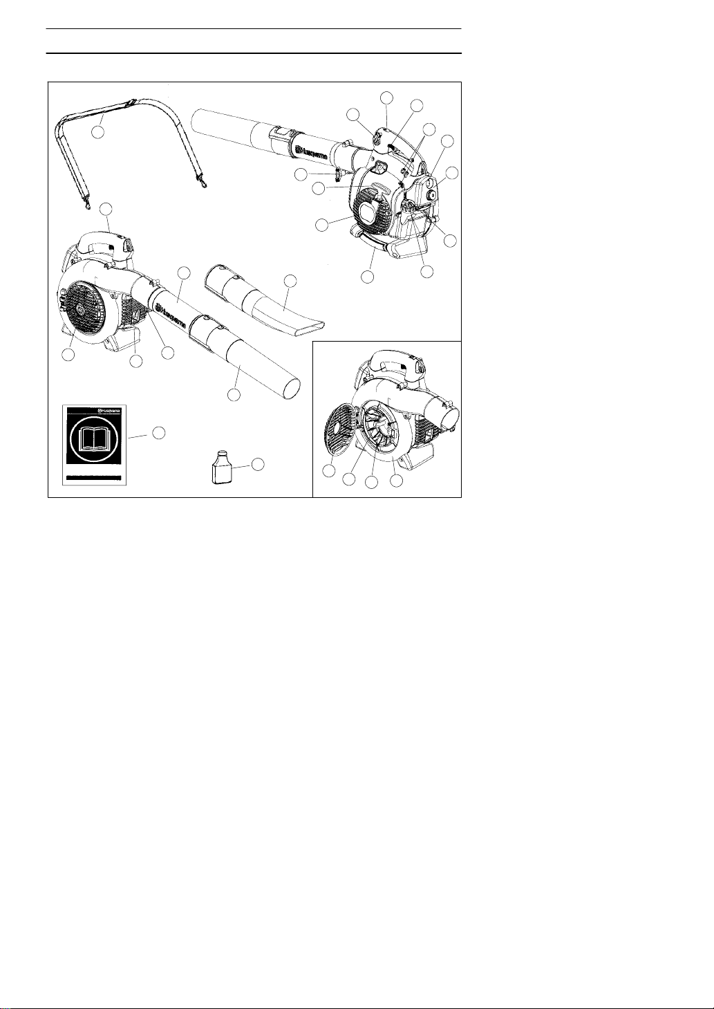
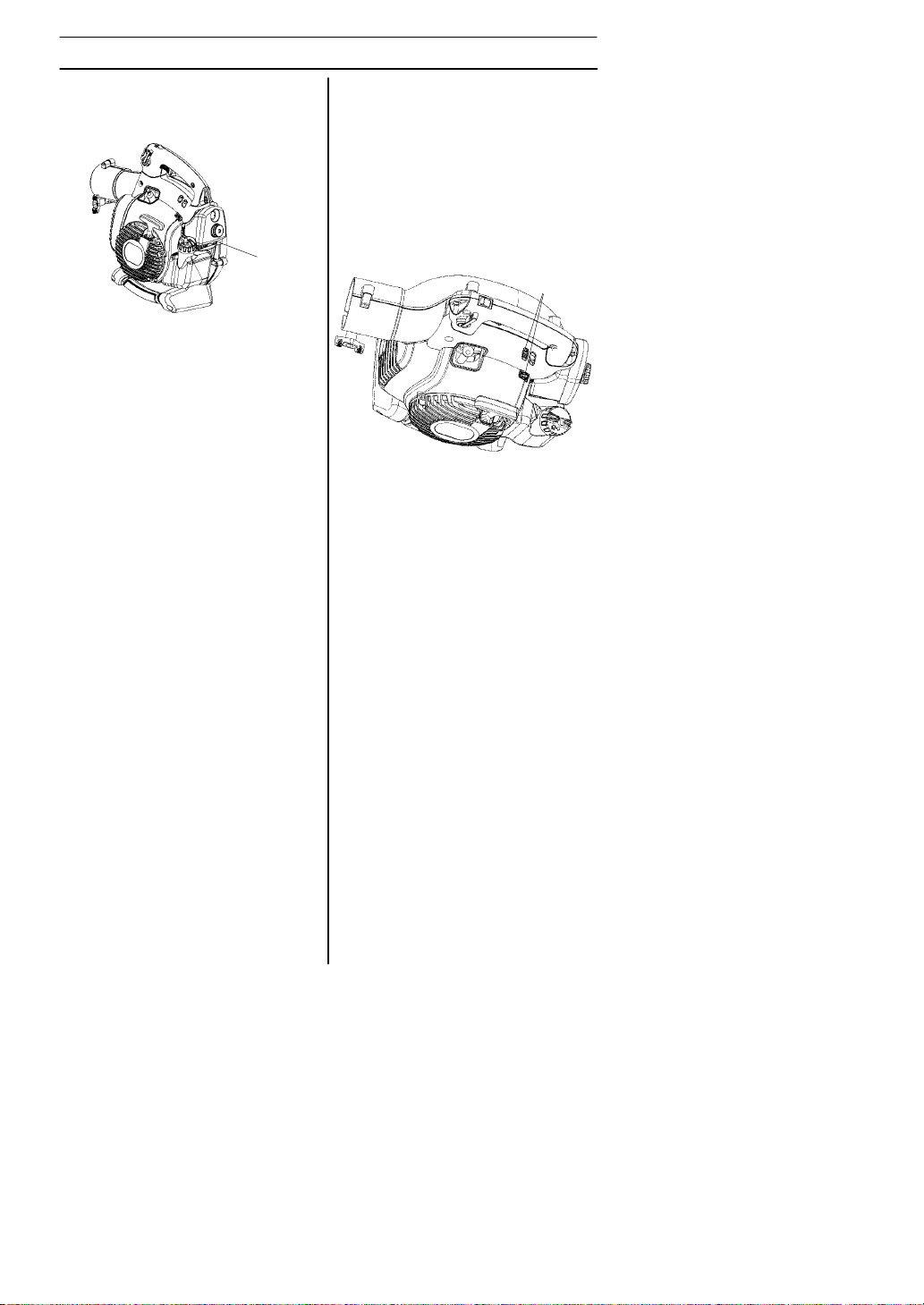
The blower
1
DESCRIPTION
3
4
2
23
9
17
21
20
22
10
19
18
16
15
11
14
25
24
1. Shoulder strap (125BV
2. Throttle trigger 14. Standard nozzle
) 13. Fan impeller
X--SERIES
10
12
13
3. STOP switch 15. High velocity nozzle
4. Variable speed control 16. Blower tube
5. Fan housing 17. Tube clamp bolt
6. Fuel cap 18. Tube clamp nut
7. Air filter 19. Muffler
8. Choke 20. Ground wire
9. Primer bulb 21. Starter handle
10. Inlet cover 22. Starter device
11. Vacuum handle 23. Carburetor adjustment screws
(125B
12. Cutters (12 5B
125BV
X--SERIES
X--SERIES
and 125BV
and 25. Operator’s manual
X--SERIES
)
) 24. 2--stroke engine oil
X- -SERIES
7
8
6
5
545154658 Rev. 2 7/10/07
English--- 6
Page 7
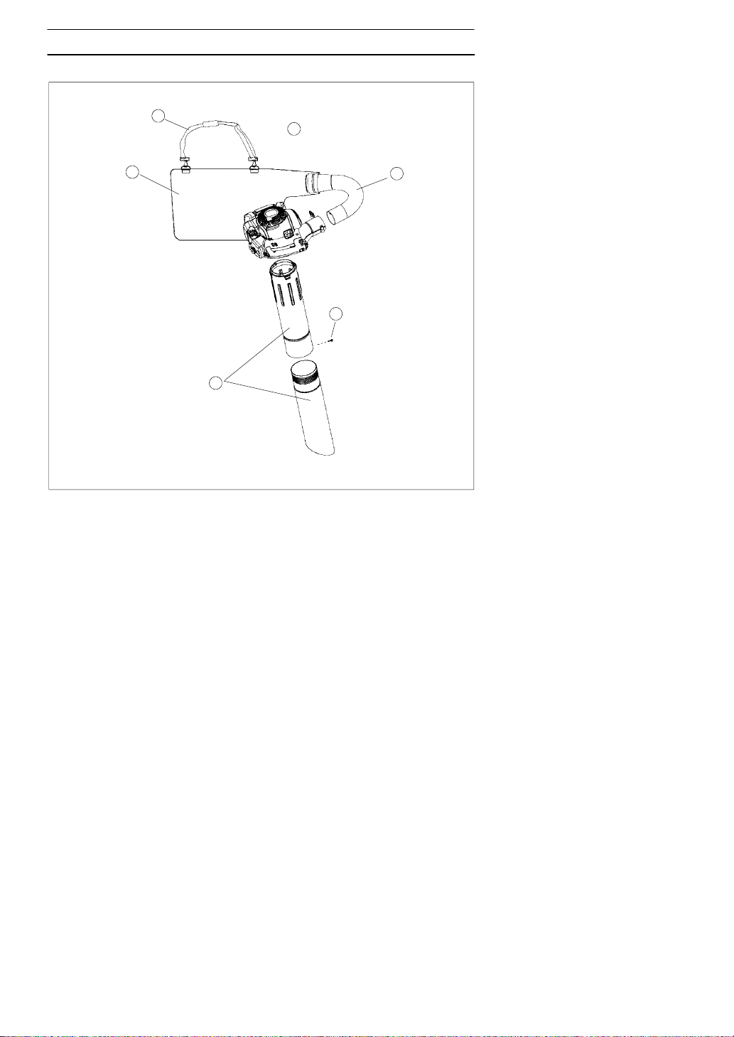
DESCRIPTION
Accessories (125B
26
23
X--SERIES
and 125BV
24
X--SERIES
21
)
22
25
21. Vacuum device with collection components consisting of items 22--26 below
22. Collection bag tube
23. Collection bag
24. Vacuum tube in two sections
25. Screw
26. Shoulder strap
545154658 Rev. 2 7/10/07
English--- 7
Page 8
DESCRIPTION
Oth
Safety equipment
The following equipment on the blower is
designed for protecting personnel and
materials. These components should
receive special attention whenever you
operate, inspect and service the blower.
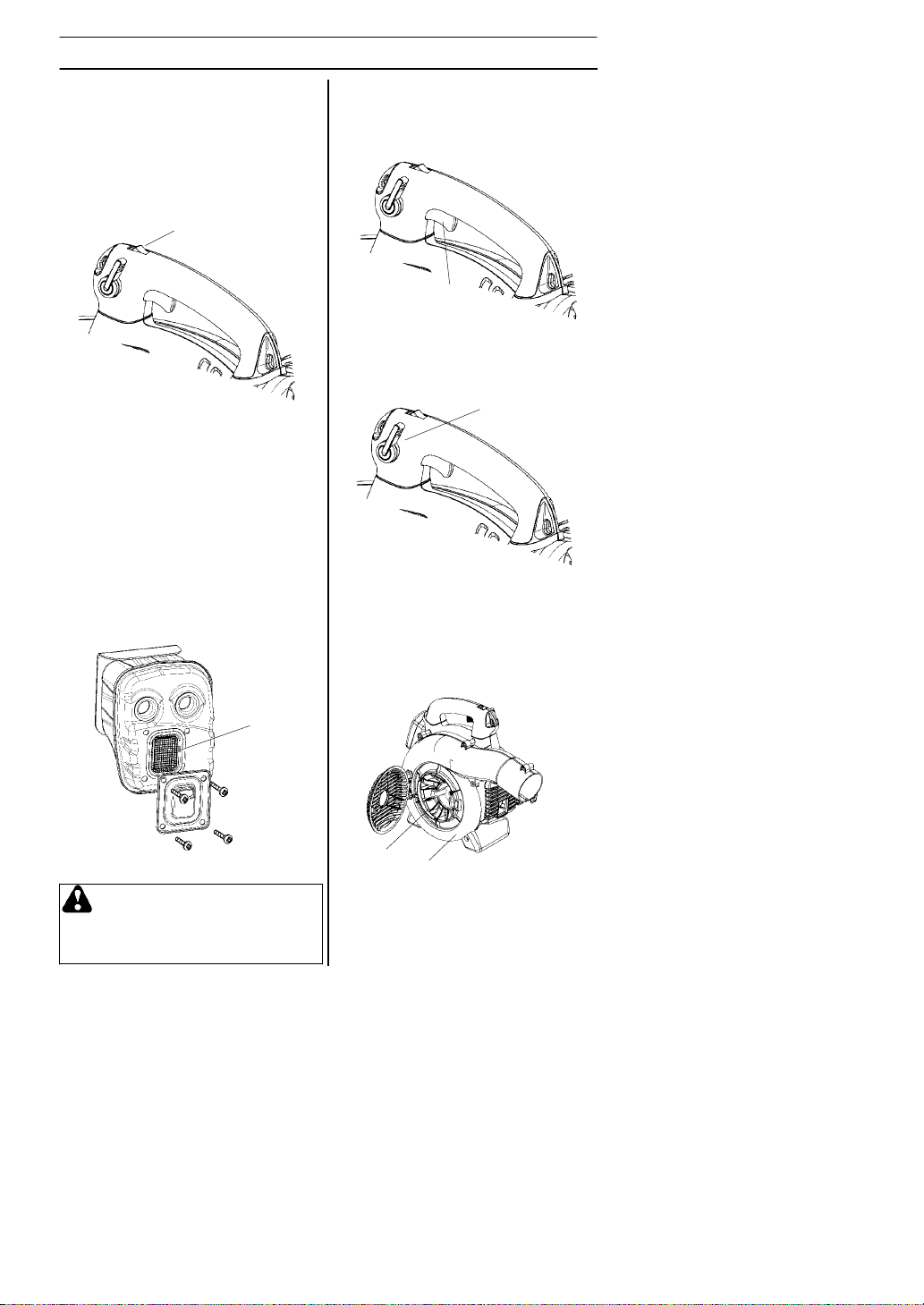
Stop switch
S The stop switch (A) is used to stop the
engine.
A
er equipment
Throttle trigger
S The speed and the output of the engine
are regulated by the throttle trigger (C).
C
Variable speed control
S The variable speed control (D) is de-
signed to allow setting engine speed as
necessary during blower use only.
Muffler
S The muffler is designed to give the low-
est possible noise level and to direct the
engine’s exhaust fumes away from the
operator. Mufflers fitted with catalytic
converters are also designed to reduce
harmful exhaust components.
S The engine exhaust fumes are hot and
can contain sparks, which may cause
fire if they come in contact with dry or
flammable material.
S Some blower models, especially those
sold in countries where the climate is
dry, are equipped with a spark arresting
screen (B). This screen must be cleaned
or replaced at specific intervals. See the
Maintenance section.
B
WARNING: The muffler is ex-
tremely hot while the engine is running and after it has stopped. DO
NOTTOUCHTHEMUFFLERIFITIS
HOT! This can cause severe burns.
D
S T oavoid causing damage to the unit, DO
NOT attempt to use the variable speed
control during starting or during vacuum
use.
Fan housing
S The blower fan housing (E) and the fan
impeller (F) provide high performance air
discharge.
F
E
545154658 Rev. 2 7/10/07
English--- 8
Page 9
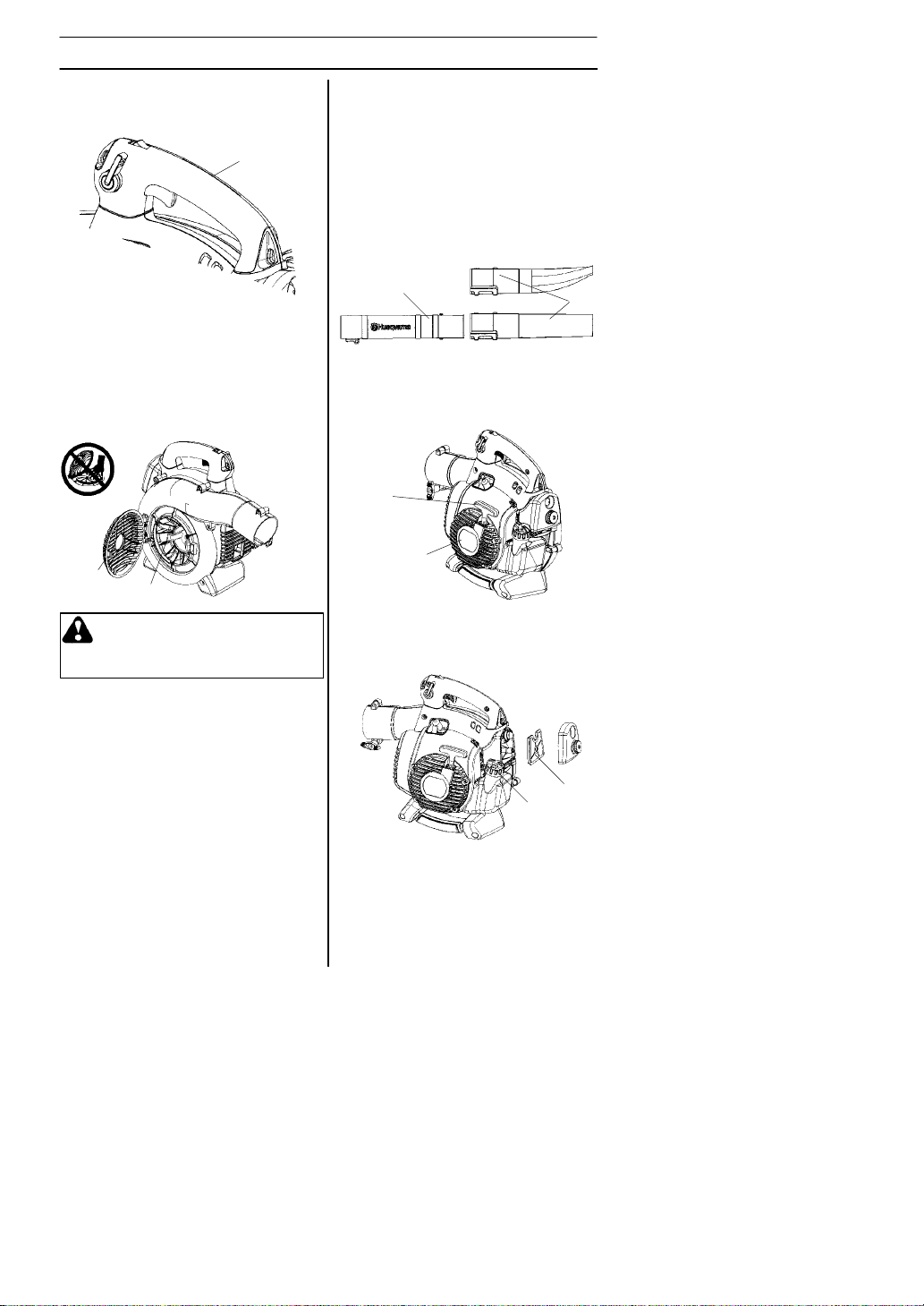
Ground wire
S The ground wire (G) reduces static
build--up during operation in dry conditions.
G
DESCRIPTION
S The nozzles (L)have a bayonet mount
for connection to the blower tube. Air is
channeled through the blower tube to the
nozzles, where the air discharge velocity
increases and the air stream discharge
pattern is formed to provide best performance. The length of the blower tube
can be adjusted by twisting the nozzle to
the left to disengage the bayonet mount
and sliding the nozzle to the appropriate
position. Twist the nozzle to the right until
a click is felt to resecure the nozzle.
Inlet cover
S An inlet cover (H) is located on the side
of the fan housing. Opening this cover
allows access for cleaning and inspecting the impeller (125B
125BV
X- -SERIES
is used, it must be fitted to the opening in
the inlet cover. Toopen the inlet cover,
use a tool to lift the edge of the cover
opposite the hinge (indicated by arrow
on inlet cover).
H
J
WARNING: Never start the blower
if the inlet cover is not closed, is
damaged or cannot be closed
(except if the vacuum tube is fitted).
X- -SERIES
only). If the vacuum tube
and
Cutters
(125B
S Two cutters (J) are fastened to the impel-
ler. The cutters are there to mulch leaves
and other debris that have been vacuumed
before they enter the collection bag.
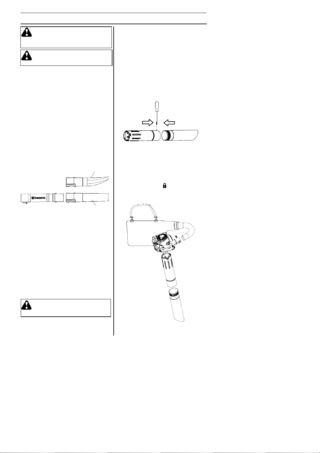
Blower tube and nozzle
NOTE:
be installed prior to initial use (see the general description of the blower on page 6).
S The blower tube (K) has a pegged slot
mounting system to the unit. T o install or
remove the blower tube (or collection bag
tube for the 125BV
clamp bolt must be removed. Align slot in
the blower air outlet with the raised rib on
the tube and insert tube until the holes in
the tube and housing align. Re--insert the
tube clamp bolt and tighten.
545154658 Rev. 2 7/10/07
and 125BV
X- -SERIES
The tube clamp bolt and nut must
X--SERIES
X--SERIES
), the tube
)
K
Starterdevice and starter handle
S The starter device (M) is located on the
side of the engine shrouding and engages the crankshaft only when the
starter handle (N) is pulled.
N
M
Fuel cap
S The fuel cap (O) is located at the rear of
the engine shrouding on the fuel tank
and has a seal to prevent fuel from leaking out.
O
Air filter
S The air filter (P) consists of a fiber filter
medium in a resilient frame. The air filter
should be cleaned at specific intervals
(see Maintenance section). Otherwise,
the blower will consume too much fuel,
the performance will be reduced and an
oily deposit may form on the spark plug
electrodes.
English--- 9
L
P
Page 10
DESCRIPTION
Choke
S The choke (Q) is located below the air
filter cover and should be used every
time the engine is cold--started.
Q
Adjusting the carburetor
NOTFORALLMODELS
S There are three adjusting screws (R) for
adjusting the carburetor:
S Low speed jet
S High speed jet
S Adjustment screw for idling
S Adjusting the carburetor involves adapt-
ing the engine to local operating conditions, e.g. climate, altitude, gasoline and
type of two--stroke engine oil used. For
details about carburetor adjustment, see
the Maintenance section.
R
545154658 Rev. 2 7/10/07
English--- 10
Page 11
FUEL HANDLING
A
f
Fuel mixture
CAUTION! The machine is equipped with
a two--stroke engine and must always be
run using a mixture of gasoline and two-stroke engine oil. It is important to accurately measure the amount of oil to be
mixed to ensure that the correct mixture is
obtained. When mixing small amounts of
fuel, even small inaccuracies can drastically affect the ratio of the mixture.
WARNING: Always ensure
there is adequate ventilation when
handling fuel.
Gasoline
CAUTION! Always use high quality
unleaded gasoline.
S This engine is certified to operate on
unleaded gasoline.
S The lowest recommended octane rating
is 87. If you run the engine on lower octane rating than 87, “knocking” can occur. This leads to an increased engine
temperature, which can result in a serious engine breakdown.
S When working at continuous high revs a
higher octane rating is recommended.
Two - -stroke oil
S For great results and performance use
HUSQVARNA two--stroke oil, which is
specially formulated for our two--stroke
engines. Mixture 1:50 (2%).
S T omaximize the life of your blower, you
may choose to use a high quality synthetic oil formulated for two--stroke
engines. Mixture 1:50 (2%).
S Never use two--stroke oil intended for
water--cooled outboard engines,
sometimes referred to as outboard oil.
S Never use oil intended for four--stroke
engines.
Gasoline
U.S. gallon U.S. fl. oz.
121/2
2 1/2 6 1/2
5127/8
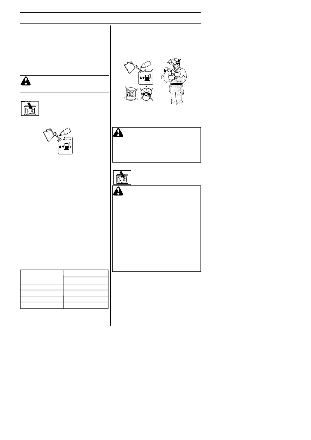
Mixing
S Always mix the gasoline and oil in a
clean container intended for fuel.
545154658 Rev. 2 7/10/07
Two --stroke oil
2% (1:50)
S
S Mix (shake) the fuel mixture thoroughly
S Do not mix more than one month’s sup-
S If the machine is not used for some time,
Fueling
lways start byfilling halfthe amount o
the gasoline to be used. Then add the
entire amount of oil. Mix (shake) the fuel
mixture. Add the remaining amount of
gasoline.
before filling the machine’s fuel tank.
ply of fuel at a time.
the fuel tank should be emptied and
cleaned.
WARNING: The catalytic con-
verter muffler gets very hot during
and after use. This also applies
during idling. Be aware of the fire
hazard, especially when working
near flammable substances and/or
vapors.
WARNING: Taking the following
precautions, will lessen the risk of
fire:
Do not smoke or place hot objects
near fuel.
Always shut off the engine before
refueling.
Always stop the engine and let it
cool for a few minutes before
refueling.
When refueling, open the fuel cap
slowly so that any excess pressure
is released gently.
Tighten the fuel cap carefully after
refueling.
Always move the machine away
from the refueling area before
starting.
English--- 11
Page 12
STARTING AND STOPPING
Min. 10 ft.
(3 m)
S Clean the area around the fuel cap.
Contamination in the tank can cause
operating problems.
S Ensure that the fuel is well mixed by shak-
ing the container before filling the tank.
Starting and stopping
WARNING: Never start the blower
if the inlet cover is not closed, is
damaged or cannot be closed
(except if the vacuum tube is fitted).
Cold engine
Primer bulb: Press the primer bulb 10
times until fuel begins to fill the bulb. The
primer bulb need not be completely filled.
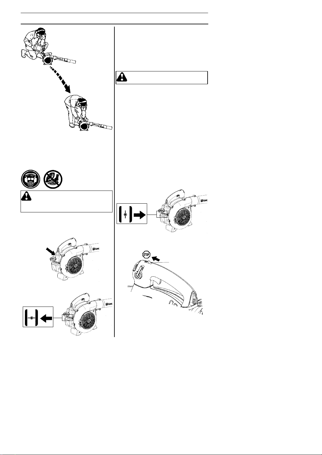
Starting: Hold the body ofthe machine on
the ground using your left hand
(CAUTION! Not with your foot!).
Firmly grip the starter rope handle with
your right hand. DO NOT squeeze
throttle trigger. Slowly pull out the cord
until you feel some resistance (the starter
pawls grip); then quickly and powerfully
pull the cord.
WARNING: Never wrap the starter
cord around your hand.
Pull starter handle until engine attempts to
run, but no more than 3 pulls. Move choke
to ½ position and pull the cord until the engine starts and runs. Allow the engine to
warm up for approximately 10 seconds;
then, move the choke to the OFF CHOKE
(opened) position.
NOTE: If engine dies, return blue engine
choke lever to the closed position and
repeat starting steps.
CAUTION! Do not pull the starter cord all
the way out and do not let go of the starter
handle when the cord is fully extended.
This can damage the machine.
Warm engine
With a warm engine, squeeze and hold the
throttle trigger. Move choke to ½ position.
Pull starter rope sharply while squeezing
throttle trigger until engine runs. Move the
choke to the OFF CHOKE (opened)
position.
Stopping
To stop the engine, push and release the
engine STOP switch (S).
Choke: Move the blue engine choke lever
over to the FULL CHOKE (closed) position.
545154658 Rev. 2 7/10/07
S
English--- 12
Page 13
USING THE BLOWER
To blow awaydebris on the
ground
Fitting the blower tube and noz zle
on the blower
WARNING: When fitting the blow-
er tube and nozzle, the engine must
be switched off.
The blower tube (T) has a pegged slot
mounting system to the unit. To install or
remove the blower tube (or collection bag
tube for 125BV
bolt must be removed. Align slot in the
blower air outlet with the raised rib on the
tube and insert tube until the holes in the
tube and housing align. Re--insert the tube
clamp bolt and tighten.
The nozzles (U) have a bayonet mount for
connection to the blower tube. Air is channeled through the blower tube to the
nozzles, where the air discharge velocity
increases and the air stream discharge pattern is formed to provide best performance.
The length of the blower tube can be adjusted by twisting the nozzle to the left to
disengage the bayonet mount and sliding
the nozzle to the appropriate position.
Twist the nozzle to the right until a click is
felt to re--secure the nozzle.
X--SERIES
T
), the tube clamp
125BV
X--SERIES
der strap for extra comfort. The strap
should be worn over the shoulder as
shown.
U
can be used with a shoul-
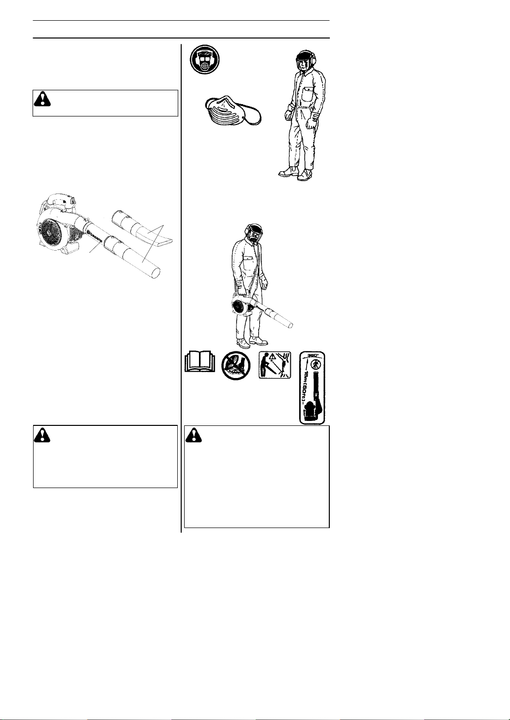
Blowing
Before you begin blowing, put on the required safety equipment.
WARNING: When working with
the blower, wear the required personal safety equipment:
1. Hearing protection.
2. Eye protection.
3. Protective gloves.
4. Face mask in dusty environments.
545154658 Rev. 2 7/10/07
WARNING: Never point the blower
nozzle at people or animals. The
high--velocity air stream can contain
particles that may cause serious
injury, especially if the blower has
previously been used for vacuuming.
Be careful, particularly if left hand
operation is applied. Avoid any direct body contact with inlet cover
area. Keep jewelry, loose clothing,
or clothing with loosely hanging
straps, ties, tassels, etc., away from
inlet cover area.
English--- 13
Page 14
USING THE BLOWER
WARNING: Never start the blower
if the inlet cover is not closed, is
damaged or cannot be closed
(except if the vacuum tube is fitted).
WARNING: Do not operate the
blower while standing on a ladder or
a stand.
Start the blower as described in the Starting
and Stopping section. Work according to the
following instructions:
1. Never blow air toward fixed objects such
as walls, large rocks, automobiles and
fences.
2. When working inside corners, blow from
the corner and inward toward the center of
the work area. Otherwise, debris can fly
up in your face and cause eye injury.
3. Never point the blower nozzle at delicate
plants.
Standard nozzle
The standard nozzle (V) is included with
the 125B, 125B
. When greater accuracy and high air
RIES
stream concentration is desired, use the
standard nozzle.
X--SERIES
and 125BV
X--SE
W
1. Open the collection bag. Insert the
collection bag tube from inside the bag to
fit in the vacuum inlet opening of the bag
as shown. Ensure elastic is seated in
groove. Close the zipper on the bag.
2. Remove the blower tube and install the
collection bag tube. Install and tighten
tube clamp bolt. Attach the carrying strap
to the collection bag loops.
3. Align arrows on lower vacuum tube and
upper vacuum tube. Pushlow er vacuum
tube into upper vacuum tube until the lower
tube is securely seated in the upper tube
(about 3 inches/7 cm). Permanently assemble the two tubes together with the
supplied screw.
-
4. Open the cover on the side of the blower
by using a screwdriver to pry up under the
edge of the cover on the side opposite the
hinge (indicated by arrow on inlet cover).
5. Press the vacuum tubes in the large
opening at the underside of the blower
and align the tabs with the slots in the
tube. Turn it until the bayonet mount
locks (lock symbols align).
V
High--velocity nozzle
The high--velocity nozzle (W) is an accessory of the blower (included with the
125B
X--SERIES
When a wider air stream and greater air
velocity is desired, use the high--velocity
nozzle.
and 125BV
X--SERIES
).
To vacuum debris from the
ground (125B
125BV
X--SERIES
X--SERIES
)
Fitting the collection bag with the
various vacuum tubes
The vacuuming device is an accessory (included with the 125BV
WARNING: When fitting the
tubes to the blower, the engine
must be switched off.
545154658 Rev. 2 7/10/07
X--SERIES
and
).
English--- 14
Page 15
USING THE BLOWER
Vacuuming
Before vacuuming, put on the required
safety equipment.
WARNING: When working with
the blower, wear the required personal safety equipment:
1. Hearing protection.
2. Eye protection.
3. Protective gloves.
4. Face mask in dusty environments.
When operating the blower, the collection
bag must be supported by the shoulder
strap. The strap should be worn over the
shoulder as shown.
WARNING: Always check that
the collection bag is intact and the
zipper is closed before starting the
blower. Never use a damaged bag.
There is risk of injury due to flying
debris. Be careful, particularly if left
hand operation is applied. Avoid any
direct body contact with the exhaust outlet area.
WARNING: Never start the blower
if the inlet cover is not closed, is
damaged or cannot be closed
(except if the vacuum tube is fitted).
WARNING: Do not operate the
blower while standing on a ladder or
a stand.
Start the blower as described in the Starting
and Stopping section. Work according to the
following instructions:
1. Do not vacuum large solid objects that
can damage the fan, such as wood, cans
(tins) or lengths of string or ribbon.
2. Do not let the vacuum tube strike the
ground.
3. The collection bag can be emptied by first
stopping the unit and then opening the zipper on the side.
545154658 Rev. 2 7/10/07
English--- 15
Page 16

MAINTENANCE
Maintenance Safety
The owner is responsible for the performance of all required maintenance as
defined in the operator’s manual.
Disconnect the spark plug before performing maintenance, except carburetor adjustments.
WARNING: Improper mainte-
nance could result in serious engine
damage or in serious injury.
Carburetor
YourHusqvarna product has been designed
and manufactured to specifications that reduce harmful emissions. After the engine
has used 8--10 tanks of fuel, the engine will
be run--in. To ensure that it continues to run
at peak performance and to minimize harmful exhaust emissions after the run--in period, ask your servicing dealer to adjust your
carburetor.
Function
S The carburetor governs the engine’s
speed via the throttle control. Air and fuel
are mixed in the carburetor.
S The T--screw (BB) regulates the throttle
setting at idle speed. If the T--screw is
turned clockwise this gives a higher idle
speed; turning it counterclockwise gives a
lower idle speed.
Basic setting
S The basic carburetor settings are ad-
justed during testing at the factory. Fine
adjustment should be carried out by a
skilled technician.
Recommended idle speed:
See “Technical data” section.
Recommended max. speed:
See “Technical data” section.
Fine adjustment of the idle speed--T
Adjust the idle speed using the idle adjustment T--screw if it is necessary to readjust.
The idle speed is correctly adjusted when
the engine will run smoothly in every position.
BB
Muffler
Some mufflers are fitted with catalytic converters. See the Technical data section to
find out if your machine is equipped with a
catalytic converter.
The muffler is designed to dampen the
noise level and to direct the exhaust fumes
away from the user. The exhaust fumes
are hot and can contain sparks, which can
result in fire if the exhaust fumes are
directed towards a dry and flammable
material.
Some mufflers are equipped with a special
spark arresting screen (CC). If your machine is fitted with this type of screen, it
should be cleaned regularly. To access the
screen, remove the outlet cover on the
front of the muffler. Use a wire brush to
clean the screen. On mufflers without a
catalytic converter the screen should be
cleaned weekly, or replaced if necessary.
On mufflers fitted with a catalytic converter
the screen should be checked and cleaned
monthly. If the screen is damaged it
should be replaced. If the screen is frequently blocked, this can be a sign that the
function of the catalytic converter is impaired. Contact your dealer to inspect the
muffler.A blocked screen will cause the
engine to overheat resulting in damage to
the cylinder and piston.
CAUTION! Never use a machine that has
a faulty or loose muffler. Ensure the muffler
bolts are tight.
545154658 Rev. 2 7/10/07
English--- 16
Page 17

MAINTENANCE
CC
DD
WARNING: Mufflers fitted with
catalytic converters get very hot
duringuseandremainsoforsome
time after stopping. This also applies at idle speed. Contact can result in burns to the skin. Remember
theriskoffire!
WARNING: Bear in mind that:
Engine exhaust fumes contain carbon monoxide, which can cause
carbon monoxide poisoning. For
this reason you should not start or
run the machine indoors, or anywhere that is poorly ventilated.
The exhaust fumes from the engine
are hot and may contain sparks
which can start a fire. Never start
the machine indoors or near flammable material!
WARNING: The inside of the
muffler contain chemicals that may
be carcinogenic. Avoid contact with
these elements in the event of a
damaged muffler.
Cooling system
The engine is equipped with a cooling
systemformaintaining the right operating
temperature.
The cooling system consists of the following components:
1. Air intake on the starter device (DD).
2. Fan blades on the flywheel (EE).
3. Cooling fins on the cylinder (FF).
4. Cylinder cowling (guides cooling air flow
against cylinder surfaces).
Clean the cooling system by brushing once
a week, or more often, if necessary.
A dirty or blocked cooling system will
cause the blower to overheat and this will
damage the cylinder and piston.
EE
FF
Air filter
The air filter (GG) must be regularly cleaned
to remove dust and dirt in order to avoid:
S Carburetor malfunctions
S Starting problems
S Loss of engine power
S Unnecessary wear to engine parts
S Excessive fuel consumption
S Elevated content of harmful exhaust
fumes.
HH
GG
Clean the filter every 25 hours, or more
regularly if conditions are exceptionally
dusty.
Cleaning the air filter
Remove the air filter cover (HH) and take out
the filter. Wash it clean in warm, soapy water.
Rinse thoroughly. Ensure that the filter is dry
before reinstalling it.
An air filter that has been in use for a long
time cannot be cleaned completely. The
filter must therefore be replaced with a new
one at regular intervals.
CAUTION! A damaged air filter must
always be replaced.
545154658 Rev. 2 7/10/07
English--- 17
Page 18

MAINTENANCE
Spark plug
The spark plug condition is influenced by:
S Incorrect carburetor adjustment.
S An incorrect fuel mixture (too much or in-
correct type of oil).
S Poor quality gasoline and/or oil
S A dirty air filter.
These factors cause deposits on the spark
plug electrodes, which may result in operating problems and starting difficulties.
If the machine is low on power, difficult to
start or runs poorly at idle speed: always
check the spark plug first before taking
any further action. If the spark plug is dirty,
clean it and check that the electrode gap is
0.024″ (0.6 mm). The spark plug should be
replaced after about a month in operation or
earlier if necessary.
0.024″ (0.6 mm)
CAUTION! Always use the recommended
spark plug type! Use of the wrong spark
plug can damage the piston/cylinder.
Maintenance schedule
Below you will find some general maintenance instructions.
Weekly maintenance
S Check the condition of the starter device,
the starter cord and the tensioning spring.
Replace damaged parts.
S Check the condition of the air intake at
the starter device. Remove debris if it is
clogged.
S Clean the outside of the spark plug. Re-
move it and check the electrode gap. Adjust the gap to 0.024″ (0.6 mm), or
replace the spark plug. Use resistor spark
plug Champion RCJ--8Y or equivalent.
S Clean the fan blades on the flywheel.
S Clean or replace the spark arresting
screen (not on mufflers with a catalytic
converter).
S Clean the carburetor area.
S Clean the air filter.
Monthly maintenance
S Clean the fuel tank.
S Clean the outside of the carburetor and
the area around it.
S Clean the fan blades on the flywheel and
the area around it.
S Check fuel lines for cracks or other dam-
age. Change if necessary.
S Change the fuel filter in fuel tank.
S Check all cables and connections. Re-
place damaged parts.
S Replace the spark plug. Use spark plug
Champion RCJ--8Y or equivalent.
S Change the air filter.
Daily maintenance
S Clean the exterior surfaces of the blower.
S Check that the variable speed control and
the throttle trigger function in a safe manner. Replace damaged parts.
S Check that the stop switch works proper-
ly. Replace if necessary.
S Clean the air filter. Replace if necessary.
S 125B
X--SERIES
Check that the inlet cover can be locked
in the closed position. Carefully check
that the fan impeller is clean, especially if
the blower has been used for collecting
debris (vacuuming).
S Check that all nuts and screws are prop-
erly tightened.
S Check that all the housings are free of
cracks. Replace damaged parts.
S 125B
X--SERIES
Check that the collection bag is intact and
that the zipper works. Replace it if necessary.
545154658 Rev. 2 7/10/07
and 125BV
and 125BV
X--SERIES
X--SERIES
:
:
English--- 18
Page 19

TECHNICAL DATA
Technical data
Engine
Cylinder volume, cu.in./cm
Cylinder bore, inch/mm 1.4/35 1.4/35 1.4/35
Stroke, inch/mm 1.130/28.7 1.130/28.7 1.130/28.7
Idle speed, rpm 2,800--3,200 2,800--3,200 2,800--3,200
Max. speed - blowing, rpm: 8,600 8,600 8,600
Max. speed - vacuuming, rpm: ---- 7,500 7,500
Max. engine output, acc. to ISO 8893,
hp/kW 1.1/0.8 1.1/0.8 1.1/0.8
Catalytic converter muffler Yes Yes Yes
Speed--regulated ignition system No No No
Ignition system
Manufacturer/type of ignition system Phelon/CD Phelon/CD Phelon/CD
Spark plug Champion Champion Champi on
3
Electrode gap, inch/mm 0.024/0.6 0.024/0.6 0.024/0.6
Fuel and lubrication system
Manufacturer/type of carburetor Zama Zama Zama
Fuel tank capacity, US pint/liter 1.05/0.5 1.05/0.5 1.05/0.5
Weight
Weight, without fuel but with blower tube
and standard nozzle fitted, lbs/kg 9.4/4.3 9.6/4.4 9.6/4.4
Sound levels
Equivalent sound pressure level, measured
according to ANSI B175.2--2000, dB(A) 70 70 71
Vibration levels
Vibration levels at handles, measured
according to ANSI B175.3--1997, m/s
At idle: 5.0 5.0 5.0
At max. speed: 11.8 11.8 11.8
125B 125B
1.7/28 1.7/28 1.7/28
RCJ--8Y RCJ--8Y RCJ--8Y
2
X--SERIES
Fan 125B 125B
Type Radial fan Radian fan Radian fan
Max.airvelocity,m/s (km/ h), standardnozzle 60 (217) 60 (217) 60 (217)
Max. air velocity, m/s (km/h), high velocity
nozzle* 76 (273) 76 (273) 76(273)
Air volume -- blowing, m
Air volume -- vacuuming, m
3
/h (cfm) 722 (425) 722 (425) 722 (425)
3
/h (cfm) ---- 756 (445) 756 (445)
*optional accessory for some models
X--SERIES
125BV
125BV
X--SERIES
X- -SERIES
Model 125B, 125B
X--SERIES
, 125BV
X--SERIES
Approved accessories Part. no.
Gutter clean--out kit 952 711918
Model 125B
X--SERIES
, 125BV
X--SERIES
Approved accessories Part. no.
Vacuum kit 952 711 913
545154658 Rev. 2 7/10/07
English--- 19
Page 20

WARRANTY STATEMENT
Y
X
SECTION 1: LIMITED WARRANT
Husqvarna warrants Husqvarna product to
the original purchaser to be free from defects
in material and workmanship from the date of
purchase for the “Warranty Period” of the
products as set forth below:
Lifetime Warranty: Ignition coils and modules.
2 Year NON--COMMERCIAL Warranty:
Blowers for non- -commercial, non--professional, non--institutional or non--income producing
use, except as herein stated.
Emission control system components necessary to comply with CARB and EPA regulations.
1 Year Warranty: All blowers used for commercial, institutional, professional, or income
producing purposes or use.
SECTION 2: HUSQVARNA ’S OBLIGATIONS UNDER THE WARRANTY
Husqvarna will repair or replace defective
components without charge for parts or labor
if a component fails because of a defect in
material or workmanship during the warranty
period.
SECTION 3: ITEMS NOT COVERED
BY THIS WARRANTY
The following items are not covered by this
warranty:
(1) Normal customer maintenance items
which become worn through normal regular use, including, but not limited to, filters,
lubricants, rewind springs, spark plugs,
and starter ropes.
(2) Natural discoloration of material due to
ultraviolet light.
SECTION 4: EXCEPTIONS AND
LIMITATIONS
This warranty shall be inapplicable to defects resulting from the following:
(1) Accident, abuse, misuse, negligence and
neglect, including stale fuel, dirt, abrasives, moisture ,rust, corrosio n ,or any
adverse reaction due to incorrect storage
or use habits.
(2) Failure to operate or maintain the unit in
accordance with the operator’s manual or
instruction sheet furnished by Husqvarna.
(3) Alterations or modifications that change
the intended use of the product or affects
the product’s performance, operation,
safety, or durability, or causes the product
to fail to comply with any applicable laws.
(4) Additional damage to parts or compo-
nents due to continued use occurring after any of the above.
REPAIR OR REPLACEMENT AS PROVIDED UNDER THIS WARRANTY IS THE
EXCLUSIVE REMEDY OF THE PURCHASER. HUSQVARNA SHALL NOT BE LIABLE
FOR ANY INCIDENTAL OR CONSEQUENTIAL DAMAGES FOR BREACH OF ANY
EXPRESS OR IMPLIED WARRANTY ON
545154658 Rev. 2 7/10/07
THESE PRODUCTS E
TENT PROHIBITED BY APPLICABLE LAW .
ANY IMPLIED WARRANTY OR MERCHANTABILITY OR FITNESS FOR A PARTICULAR PURPOSE ON THESE PRODUCTS IS LIMITED IN DURATION TO THE
WARRANTY PERIOD AS DEFINED IN THE
LIMITE D WARRANTYST ATEMENT. HUSQVARNA RESERVES THE RIGHT TO
CHANGE OR IMPROVE THE DESIGN OF
THE PRODUCT WITHOUT NOTICE, AND
DOES NOT ASSUME OBLIGATION TO UPDATE PREVIOUSLY MANUFACTURED
PRODUCTS.
Some states do not allow the exclusion of incidental or consequential damages, or limitations on how long an implied warranty lasts,
so the above limitations or exclusions may not
apply to you. This warranty gives you specific
legal rights, and you may also have other
rights which vary from state to state.
CEPT TO THE EX-
SECTION 5: CUSTOMER RESPONSIBILITIES
The product must exhibit reasonable care,
maintenance, operation, storage and general upkeep as written in the maintenance
section of the operator’s manual. Should an
operational problem or failure occur, the
product should not be used, but delivered
as is to an authorized Husqvarna dealer for
evaluation. Proof of purchase, as explained
in Section 6, rests solely with the customer.
SECTION 6: PROCEDURE TO OBTAIN WARRANTY CONSIDERATION
It is the Owner’s and Dealer’s responsibility to
make certain that the Warranty Registration
Card is properly filled out and mailed to
Husqvarna. This card should be mailed within
ten (10) days from the date of purchase in
order to confirm the warranty and to facilitate
post- -sale service.Proof of purchase must be
presented to the authorized Husqvarna dealer
in order to obtain warranty service. This proof
must include date purchased, model number,
serial number, and complete name and address of the selling dealer.To obtain the benefit
of this warranty, the product believed to be
defective must be delivered to an authorized
Husqvarna dealer in a timely manner, no later
than thirty (30) days from date of the operational problem or failure. The product must be
delivered at the owner’s expense. Pick- -up
and delivery charges are not covered by this
warranty. An authorized Husqvarna dealer
can be normally located through the “Yellow
Pages” of the local telephone directory or by
calling 1--800--438--7297 for a dealer in your
area.
7349 Statesville Road
CHARLOTTE, NC 28269
English--- 20
Page 21

U.S. EPA / CALIFORNIA / ENVIRONMENT CANADA
Y
EMISSION CONTROL WARRANTY STATEMENT
OUR WARRANTYRIGHTSAND
OBLIGATIONS:
The U.S. Environmental Protection Agency,
California Air Resources Board, Environment
Canada and HUSQVARNA are pleased to
explain the emissions control system warranty
on your year 2007 and later small off- -road
engine. In California, all small off--road engines must be designed, built, and equipped
to meet the State’s stringent anti--smog standards. HUSQVARNA must warrant the emission control system on your small off- -road
engine for the periods of time listed below provided there has been no abuse, neglect, or
improper maintenance of your small off--road
engine. Y our emission control system includes
parts such as the carburetor, the ignition system and the fuel tank (California only). Where
a warrantable condition exists, HUSQVARNA
will repair your small off--road engine at no
cost to you. Expenses covered under warranty include diagnosis, parts and labor.
MANUFACTURER’S WARRANTY
COVERAGE:
If any emissions related part on your engine
(as listed under Emissions Control Warranty Parts List) is defective or a defect in the
materials or workmanship of the engine
causes the failure of such an emission related part, the part will be repaired or replaced by HUSQVARNA.
OWNER’S WARRANTY RESPONSIBILITIES:
As the small off--road engine owner, you are
responsible for the performance of the required maintenance listed in your operator’s
manual. HUSQVARNA recommends that
you retain all receipts covering maintenance
on your small off--road engine, but HUSQVARNA cannot deny warranty solely for the
lack of receipts or for your failure to ensure
the performance of all scheduled maintenance. As the small off--road engine owner,
you should be aware that HUSQVARNA
may deny you warranty coverage if your
small off--road engine or a part of it has
failed due to abuse, neglect, improper maintenance, unapproved modifications, or the
use of parts not made or approved by the
original equipment manufacturer. You are
responsible for presenting your small off-road engine to a HUSQVARNA authorized
repair center as soon as a problem exists.
Warranty repairs should be completed in a
reasonable amount of time, not to exceed
30 days. If you have any questions regarding your warranty rights and responsibilities,
you should contact your nearest authorized
service center or call HUSQVARNA at
1--800--438--7297.
WARRANTYCOMMENCEMENT
DATE:
The warranty period begins on the date the
small off--road engine is purchased.
LENGTH OF COVERAGE:
This warranty shall be for a period of two
years from the initial date of purchase.
WHAT IS COVERED: REPAIR OR
REPLACEMENT OF PARTS.
Repair or replacement of any warranted
part will be performed at no charge to the
owner at an approved HUSQVARNA servicing center. If you have any questions regarding your warranty rights and responsibilities, you should contact your nearest authorized service center or call HUSQVARNA at 1--800--438--7297.
WARRANTY PERIOD:
Any warranted part which is not scheduled
for replacement as required maintenance,
or which is scheduled only for regular inspection to the effect of “repair or replace
as necessary” shall be warranted for 2
years. Any warranted part which is scheduled for replacement as required maintenance shall be warranted for the period of
time up to the first scheduled replacement
point for that part.
DIAGNOSIS:
The owner shall not be charged for diagnostic labor which leads to the determination that a warranted part is defective if the
diagnostic work is performed at an approved HUSQVARNA servicing center.
CONSEQUENTIAL DAMA GES:
HUSQVARNA may be liable for damages to
other engine components caused by the failure of a warranted part still under warranty.
WHAT IS NOT COVERED:
All failures caused by abuse, neglect, or
improper maintenance are not covered.
ADD--ON OR MODIFIED PARTS:
The use of add--on or modified parts can be
grounds for disallowing a warranty claim.
HUSQVARNA is not liable to cover failures
of warranted parts caused by the use of
add--on or modified parts.
HOW TO FILE A CLAIM:
If you have any questions regarding your
warranty rights and responsibilities, you
should contact your nearest authorized service center or call HUSQVARNA at
1--800--438--7297.
WHERE TO GET WARRANTY SERVICE:
Warranty services or repairs shall be provided at all HUSQVARNA service centers.
Call 1--800--438--7297.
545154658 Rev. 2 7/10/07
English--- 21
Page 22

U.S. EPA / CALIFORNIA / ENVIRONMENT CANADA
EMISSION CONTROL WARRANTY STATEMENT
MAINTENANCE, REPLACEMENT
AND REPAIR OF EMISSION RELATED PARTS:
Any HUSQVARNA approved replacement
part used in the performance of any warranty maintenance or repair on emission related parts will be provided without charge
to the owner if the part is under warranty.
This engine is certified to be emissions compliant for the following use:
Moderate (50 hours)
Intermediate (125 hours)
Extended (300 hours)
EMISSION CONTROL WARRANTY
PARTS LIST:
Carburetor, Ignition System: Spark Plug
(covered up to maintenance schedule), Ignition Module, Muffler including Catalyst, Fuel
Tank (California only).
MAINTENANCE STATEMENT:
The owner is responsible for the performance of all required maintenance as defined in the operator’s manual.
545154658 Rev. 2 7/10/07
English--- 22
Page 23

EN FR ES
Page 24

INDICE
Indice
Introducción 45...................
Símbolos utilizados en este manual 46.
Reglas de seguridad 47.............
Descripción 49.....................
Manipulación del combustible 54.....
Arranque y parada 56...............
Manejo 57.........................
Maintenimiento 60..................
Datos técnicos 63..................
El mantenimiento, el reemplazo, o la reparación de los dispositivos del control de emisión
y el sistema se pueden realizar por cualquier
establecimiento o individuo de la reparación
delmotorparausofueradecarretera.
Antes de arrancar, observe lo
siguiente:
Husqvarna AB trabaja constantemente para
perfeccionar sus productos y se reserva, por
lo tanto, el derecho a introducir modificaciones en la construcción y el diseño sin
previo aviso. La exposición prolongada al
ruido puede causar daños crónicos en el
oído. Use siempre protectores auriculares
homologados.
Este manual describe detalladamente la
forma de utilizar y mantener el soplador de
hojas, las medidas de mantenimiento regular, las medidas que deben tomarse para
reducir los riesgos en el empleo de la
máquina y el funcionamiento y manejo
de los componentes de seguridad.
¡Atención! Todas las personas que trabajan con la máquina deben leer y comprender el capítulo que trata de la seguridad.
Este manual está redactado para personas que no tienen los conocimientos necesarios para la localización de fallos, las
medidas de servicio esenciales y la reparación de la máquina.
En el manual y en la máquina hay símbolos de advertencia. Si alguno de estos
símbolos se ha deformado o desgastado,
debe sustituirse por uno nuevo lo antes
posible. Téngase en cuenta que también
hay símbolos de advertencia fundidos en
algunas piezas de la máquina.
El soplador de hojas se utiliza para limpiar el
suelo de hojas y escombros, soplando. Durante el trabajo, el operario debe estar afirmado en el suelo.
El período de conformidad de las emisiones
referido en la etiqueta de las emisiones indica
el número de las horas de funcionamiento para
las cuales el motor se ha comprovado para
satisfacer requisitos federales de las emisiones. Categoría C = 50 horas, B = 125 horas, y A = 300 horas.
Para la referencia por favor, complete la
información siguiente que seá necesaria para el mantenimiento futuro de su
aparato:
Número de modelo:
Número de serie:
Fecha de la compra:
Distribuidor:
ADVERTENCIA: Bajo ningu-
na circunstancia debe modificarse la configuración original
de la máquina sin autorización
del fabricante. Utilizar siempre recambios originales. Las modificaciones y/o la utilización de accesorios no autorizadas pueden
ocasionar accidentes graves o
incluso la muerte del operador o
de terceros. Su garantía puede no
cubrir el daño causada por el uso
de accesorios o de piezas de recambio que no se recomiendan.
Para atención al cliente, llama al:
1-800-487-5951
Visítanos en nuestra pagina de red:
www.husqvarna.com
545154658 Rev. 2 7/10/07
Spanish ---45
Page 25

SIMBOLOS UTILIZADOS EN ESTE MANUAL
Símbolo Descripción Ubicación Símbolo Descripción Ubicación
El control y/o mantenimiento debe
efectuarse con el
motor parado y la
bujía desconectada.
La máquina debe
limpiarse regularmente.
Deben utilizarse gafas
protectoras o visera
homologadas.
Deben utilizarse gafas
protectoras o visera
homologadas, protectores auriculares, y
mascarilladefiltropara
protección en presencia
de polvo..
¡ADVERTENCIA!
El soplador de hojas
puede ser peligroso!
La utilización descuidada o errónea puede
causar lesiones
graves e incluso
mortales.
Lea detenidamente el
manual de instrucciones y asegúrese de
entender su contenido
antes de utilizar
la máquina.
¡ADVERTENCIA!
Controle que la cubierta
de admisión esté bloqueada en posición
cerrada o que el tubo
de admisión esté montado. No toque el ventilador a menos que el
aparato esté apagada,
que el ventilador haya
dejado de moverse y
que la bujía esté
desconectada.
X
X
X
XX
XX
XX
XX
¡ADVERTENCIA!
El aventador de hojas
puede despedir objetos
con mucha fuerza, y
pueden rebotar.
Ello puede provocar
heridas en los ojos.
El operario del soplador de hojas debe
cuidar que ninguna
persona ni animal se
acerque a menos de
15 metros. Cuando
haya varios operarios
trabajando en el mismo lugar de trabajo, la
distancia de seguridad
entre ellos debe
serde15metros.
Estrangulador
Repostaje de
combustible
Botón de parada
Instrucciones para
abrir la cubierta de
admisión
XX
XX
X
X
X
X
Utilice siempre guantes
protectores homologados.
545154658 Rev. 2 7/10/07
XX
Los demás símbolos/pegatinas que
aparecen en la máquina corresponden a
requisitos de homologación específicos
en determinados mercados.
Spanish ---46
Page 26

REGLAS DE SEGURIDAD
Equipo de protección personal
Las personas que manejen el aventador
de hojas deben utilizar este equipo de protección personal:
1. Protección auricular aprobada.
2. Protección de ojos aprobada.
3. Guantes protectores homologados.
4. Botas o zapatos gruesos con suela contra resbalones.
5. Mascarilla de filtro para protección en
presencia de polvo.
Reglas de personal
Las personas que utilizan la máquina deben cumplir estos requisitos:
S Leer y comprender el contenido de este
manual de instrucciones.
S No utilizar prendas de vestir sueltas,
pañuelo de cuello o collar, ni tampoco
tener el pelo largo, debido al riesgo de
que entren en la máquina.
S No estar bajo los efectos del alcohol o
medicamentos, ni fatigadas.
S Deben ser mayores de edad.
S T engasiempre a mano el equipo de
primeros auxilios.
Seguridad con el combustible
¡ADVERTENCIA! El combus-
tible utilizado en la máquina tiene
las siguientes características
peligrosas:
1. El líquido, sus vapores y los
gases de escape son tóxicos.
2. Puede producir irritaciones
cutáneas.
3. Es muy inflamable.
Para manipular el combustible de la
máquina hay unas reglas de seguridad
especiales que se describen en el sección
Manipulación del combustible.
545154658 Rev. 2 7/10/07
Silenciador
El silenciador está diseñado para que el
nivel de sonido sea el más bajo posible y
para despedir los gases residuales del motor fuera del operario. El silenciador equipado con catalizador está también diseñado
para reducir las sustancias nocivas en los
gases de escape.
¡ADVERTENCIA! Los gases del
motor son muy calientes y pueden
contener chispas, que a su vez pueden ocasionar incendios. Por eso,
nunca arranque la máquina en ambientes cerrados o cerca de material
inflamable.
¡ADVERTENCIA! El silenciador
con catalizador se calienta mucho
durante el uso y permanece caliente
aún luego de apagado el motor. Lo
mismo vale para la marcha en ralentí.
Su contacto puede quemar la piel.
¡Tenga en cuenta el peligro de
incendio!
Equipo de seguridad
¡ADVERTENCIA! El aventador
de hojas no debe usarse si algún
dispositivo de seguridad o protección está desmontado o averiado, o
no funciona.
Para prevenir accidentes, el aventador incorpora varios dispositivos de seguridad y
protecciones que se explican en la descripción general de la máquina.
Los dispositivos de seguridad y la protecciones también requieren un control y mantenimiento regular. Las medidas a tomar y
los intervalos se describen en el sección
Mantenimiento.
Seguridad en el empleo del
soplador de hojas
S Dentro de la zona de trabajo, de 15 met-
ros, no debe haber terceras personas.
S El aventador de hojas puede despedir
objetos con mucha fuerza, y pueden rebotar. Ello puede provocar heridas en los
ojos.
S No dirija el chorro de aire hacia personas
ni animales.
S Pare el motor antes de montar o des-
montar accesorios o piezas.
S No trabaje con la máquina sin que estén
montadas las protecciones.
S Para evitar la inhalación de gases de es-
cape, no haga funcionar la máquina en
espacios mal ventilados.
S Apague el motor y deje que se enfríe
antes de reabastecerlo de combustible.
Aleje el aparato al menos 3 metros del
lugar de abastecimiento antes de intentar
arrancarla.
Spanish ---47
Page 27

REGLAS DE SEGURIDAD
S El silenciador del catalizador está muy cal-
iente tanto durante el uso como después de
parar la máquina. Incluso durante la marcha
en ralentí. Preste atención al peligro de incendio, especialmente al trabajar cerca de
sustancias inflamables y/o gases.
S Proceda con cuidado, especialmente si
maneja la máquina con la mano izquierda.
Evite el contacto directo del cuerpo con la
zona de la tapa de entrada de aire. Mantenga joyería, ropa suelta, ropa con corbatas, tiras, borlas, etc., lejos del área de la
tapa de entrada.
S El soplador de hojas no se debe utilizar
montado en escaleras ni andamios.
Otrasreglasdeseguridad
S No utilice la máquina en horas en que pue-
da molestar a otras personas: por ejemplo,
a primera hora de la mañana o a última
hora de la tarde. Observe la reglamentación local. El horario de uso común es de
09.00--17.00, de lunes a viernes.
S No acelere más de lo necesario para reali-
zar los trabajos.
S Revise el soplador antes de usarlo; espe-
cialmente el silenciador, la toma de aire y
el filtro de aire.
S Antes de soplar, quite la suciedad que
pueda haber en la máquina, con un rastrillo o un cepillo.
S Para trabajar en lugares polvorientos,
humedezca ligeramente la zona de trabajo
con una manguera.
S Ahorre agua utilizando el soplador de
hojas en vez de limpiar con agua: por
ejemplo, canaleras, fachadas, terrazas,
jardines, etc.
S T engacuidado con los niños, animales
domésticos, ventanas abiertas y
automóviles recién lavados. Sople los
escombros de forma segura.
S Utilice tubo de soplado y boquilla para
acercar la corriente de aire al suelo tanto
como sea posible.
S Después de soplar, recoja los escombros
y échelos en un cubo de basura.
545154658 Rev. 2 7/10/07
Spanish ---48
Page 28

Soplador de hojas
1
DESCRIPCION
3
4
2
23
9
17
21
20
22
10
19
18
16
15
11
14
25
24
1. Arnés (125BV
2. Acelerador 14. Boquilla estándar
) 13. Ventilador
X--SERIES
10
12
13
3. Interruptor de parada (STOP) 15. Boquilla de alta velocidad
4. Control de velocidad variable 16. Tubo de soplador
5. Cubierta del ventilador 17. Perno de bloqueo del tubo
6. Tapa del depósito de combustible 18. Tuerca de bloqueo del tubo
7. Filtro de aire 19. Silenciador
8. Estrangulador 20. Alambre para tierra
9. Bomba de combustible 21. Mango de arranque
10. Tapa de entrada de aire 22. Aparato de arranque
11. Mango de aspirador 23. Tornillos de ajuste del carburador
(125B
12. Cuchillas (125B
125BV
X--SERIES
X--SERIES
y125BV
X- -SERIES
)
) 24. Aceite para motores de 2 tiempos
X- -SERIES
y 25. Manual de instrucciones
7
8
6
5
545154658 Rev. 2 7/10/07
Spanish ---49
Page 29

DESCRIPCION
Accesorios (125B
23
X--SERIES
26
y125BV
24
X--SERIES
21
)
22
25
21. Dispositivo del aspirador con los componentes de la colección que consisten en
puntos 22--26
22. Tubo de la bolsa de colección
23. Bolsa de colección
24. Tubo de aspiración (2 piezas)
25. Tornillo
26. Arnés
545154658 Rev. 2 7/10/07
Spanish ---50
Page 30

DESCRIPCION
O
Equipo de seguridad
Los equipos que se describen a continuación están diseñados y construidos para
reducir los riesgos del usuario y el entorno.
Preste especial atención a estas piezas en
el empleo, control y mantenimiento de la
máquina.
Interruptor de parada
S Se utiliza el interruptor de parada (A)
para parar el motor.
Silenciador
S El silenciador está diseñado para que el
nivel de sonido sea el más bajo posible y
para despedir los gases residuales del
motor fuera del operario. El silenciador
equipado con catalizador está también
diseñado para reducir las sustancias nocivas en los gases de escape.
S Los gases de escape están muy calientes
y pueden contener chispas que pueden
causar incendios si entran en contacto con
materiales fácilmente inflamables.
S Para algunos países de clima seco, el
silenciador incorpora una rejilla apagachispas (B) que debe limpiarse/
cambiarse a intervalos regulares. Vea la
sección Mantenimiento.
A
B
tros equipos
Acelerador
S El acelerador regula el régimen y la po-
tencia del motor. (C).
C
Control de v elocidad variable
S El control de velocidad variable (D)
permite ajustar la velocidad del motor
según sea necesario mientras se utiliza
el soplador.
D
S Para evitar que el aparato resulte daña-
da, NO intente utilizar el control de velocidad variable durante el uso del aspirador.
Cubiertadel ventilador
S La cubierta de ventilador (E) ye el venti-
lador (F) proporcionan el paso de aire
adecuado por la máquina.
¡ADVERTENCIA! Durante el
funcionamiento y durante unos
instantes después de parar la
máquina, el silenciador está muy
caliente.NO TOQUE EL SILENCIADOR SI ESTACALIENTE: riesgo de
quemaduras.
545154658 Rev. 2 7/10/07
F
E
Spanish ---51
Page 31

DESCRIPCION
Alambreparatierra
S El alambre para tierra (G) reduce
la acumulación estática durante la
funcionamiento en condiciones secas.
G
Tapa de entrada de aire
S Hay una tapa de entrada de aire (H) en el
lateral del cubierta del ventilador. Al abrir
esta tapa, se puede acceder al ventilador
para limpiarlo y inspeccionarlo
(125B
mente).Siseutilizaeltuboaspirador,se
deberá fijar en la abertura de la tapa de entrada de aire. Para abrir la tapa de entrada
de aire, utilice una herramienta para lavantar
el borde de la tapa contrario a la bisagra (se
indicada mediante una flecha en la tapa de
entrada de aire).
X- -SERIES
y 125BV
X- -SERIES
sola-
S El tubo de soplador (K) dispone de un sis-
tema de ranura de bloqueo para montarlo
en el aparato. Para instalar o desinstalar
el tubo de soplador (o el tubo de la bolsa
de aspiración 125BV
el perno de bloqueo del tubo. Alinee la ranura que hay en la salida de aire del soplador con el reborde en relieve del tubo e
introduzca el tubo hasta que los orificios
de éste y el armazón queden alineados.
Vuelva a colocar y apretar el perno sujetador.
S La boquillas (L) dispone de un sistema de
conexión en bayoneta para acoplarla en el
tubo de soplador. El aire se canaliza a través del tubo de soplador hasta la boquillas, en la que aumenta la velocidad de
descarga del aire y se estable el modelo
de descarga del caudal de aire para aumentar el rendimiento. La longitud del tubo
de soplador se puede ajustar girando la
boquilla hacia la izquierda para soltar la
conexión en bayoneta y deslizando la boquilla hasta la posición adecuada. Para
volver a bloquear la boquilla, gírela hacia la
derecha hasta que oiga un chasquido.
K
X--SERIES
), remueva
L
H
J
¡ADVERTENCIA! No ponga en
marcha el soplador si la tapa de entrada de aire está abierta, dañada, o
no puede cerrarse. Esta instrucción
no tiene validez si hay instalado un
tubo aspirador.
Cuchillas
(125B
X- -SERIES
S En el rodete del ventilador hay dos cuchil-
las (J) para triturar hojas y otros residuos
antes de que pasen por el bolsa de colección.
Tubo de soplador y boquilla
NOTA:
tuerca deben ser instalados antes de uso
inicial (vea la descripción general de la
máquina en la página 49).
545154658 Rev. 2 7/10/07
and 125BV
El perno de bloqueo del tubo y la
X--SERIES
)
Dispositivo y mango de arranque
S El dispositivo de arranque (M) se encuen-
tra situado en el lado del cárter del motor y
sólo se engrana en el cigüeñal cuando se
tira de la mango de arranque (N).
N
M
Tapa del depósito de c ombu stible
S El tapa del depósito está situado en la
parte posterior del cárter del motor y
lleva una junta que impide la fuga de
combustible.
Spanish ---52
Page 32

DESCRIPCION
P
O
Filtro de aire
S El filtro de aire (P) es una estructura
elástica de material de fibra para filtros.
El filtro debe limpiarse a intervalos regulares (vea la sección Mantenimiento);
de lo contrario, el consumo de combustible es excesivo, se reduce la potencia
y hay riesgo de que se aceite la bujía.
Estrangulador
S El estrangulador (Q) está situado debajo
de la cubierta del filtro de aire y debe utilizarse cada vez que se arranca en frío
el motor.
Reglage del carburador
NO ESTÁ DISPONIBLE EN TODOS
LOS MODELOS
S El carburador tiene tres tornillos de
ajuste:
S Surtidor de régimen bajo
S Surtidor de régimen alto
S T ornillode ajuste de ralentí
S El carburador se ajusta para adaptar el
motor a las condiciones locales como
clima, altitud y gasolina. En lo referente
al ajuste del carburador, vea la sección
Mantenimiento.
R
545154658 Rev. 2 7/10/07
Q
Spanish ---53
Page 33

MANIPULACION DEL COMBUSTIBLE
Carburante
¡NOTA! El motor de la máquina es de dos
tiempos y debe funcionar con una mezcla
de gasolina y aceite para motores de dos
tiempos. Para obtener una mezcla con las
proporciones correctas debe medirse con
precisión la cantidad de aceite a mezclar.
En la mezcla de pequeñas cantidades de
combustible, los errores más insignificantes en la medición del aceite influyen
considerablemente en las proporciones de
la mezcla.
ADVERTENCIA: Para hacer la
mezcla, compruebe que haya buena ventilación.
Gasolina
¡NOTA! Use siempre gasolina sin plomo
de alta calidad.
S Este motor está habilitado para fun-
cionar con gasolina sin plomo.
S El octanaje mínimo recomendado es de 87
octanos. Si usa gasolina de menos de 87
octanos, el motor puede pistonear. Esto
aumenta la temperatura del motor y puede
ocasionar averías graves del mismo.
S Para trabajar durante mucho tiempo en
altas revoluciones se recomienda el uso
de gasolina con más octanos.
Aceite para motores de dos tiempos
S Para obtener el mejor resultado y funcio-
namiento, use el aceite HUSQVARNA
para motores de dos tiempos, que ha
sido elaborado especialmente para nuestros motores de dos tiempos. Proporción
de mezcla 1:50 (2%).
S Para maximizar la vida de su soplador,
usted puede elegir utilizar un aceite sintético de alta calidad, formulado y que ha sido
elaborado para motores de dos tiempos.
Proporción de mezcla 1:50 (2%).
S No utilice nunca aceite para motores de
dos tiempos fuera borda refrigerados por
agua (outboard oil).
S No utilice nunca aceite para motores de
cuatro tiempos.
Aceite para
Gasolina
Litros Litros
50,10
10 0,20
15 0,30
Mezcla
S Siempre haga la mezcla de gasolina y
aceite en un recipiente limpio, homologado para gasolina.
S Primero, ponga la mitad de la gasolina
que se va a mezclar. Luego, añada todo
el aceite y agite la mezcla. A continuación, añada el resto de la gasolina.
S Agite bien la mezcla de combustible
antes de ponerla en el depósito de combustible de la máquina.
S No mezcle más combustible que el ne-
cesario para utilizar un mes como máximo.
S Si no se ha utilizado la máquina por un
tiempo prolongado, vacíe el depósito de
combustible y límpielo.
ADVERTENCIA: El silenciador
del catalizador se calienta mucho,
tanto durante el funcionamiento
como después de la parada.
Incluso funcionando éste en ralentí. Tenga presente el peligro de
incendio, especialmente al manejar
sustancias y/o gases inflamables.
motores de dos
tiempos
2% (1:50)
545154658 Rev. 2 7/10/07
Spanish ---54
Page 34

MANIPULACION DEL COMBUSTIBLE
Repostaje
ADVERTENCIA: Las siguientes
medidas preventivas reducen el riesgo de incendio:
No fume ni ponga objetos calientes
cerca del combustible.
No haga nunca el repostajecon el
motor en marcha. Apague el motor
y deje que se enfríe unos minutos
antesderepostar.
Para repostar, abra despacio la
tapa del depósito de combustible
para evacuar lentamente la eventual sobrepresión.
Después de repostar, apriete bien
la tapa del depósito de combustible. Antes de arrancar, aparte
siempre la máquina del lugar de
repostaje.
Min. 3 m
S Limpie alrededor de la tapa del depósito.
Los residuos en el depósito ocasionan
problemas de funcionamiento.
S Asegúrese de que el combustible esté
bien mezclado sacudiendo el recipiente
antes de llenar el depósito.
545154658 Rev. 2 7/10/07
Spanish ---55
Page 35

ARRANQUE Y PARADA
Arranque y parada
¡ADVERTENCIA! No ponga en
marcha el soplador si la tapa de entrada de aire está abierta, dañada, o
no puede cerrarse. Esta instrucción
no tiene validez si hay instalado un
tubo aspirador.
Motor frio
Bombadecombustible: Presione 10
veces la burbuja de goma de la bomba de
combustible hasta que comience a llenarse de combustible. No es necesario
llenarla totalmente.
Estrangulador: Coloque la palanca azul
del estrangulador de la motor a la posición
FULL CHOKE (estrangulamiento).
NOTA: Si el motor se apaga, coloque la
palanca azul del estrangulador de la motor a
la posición estrangulamiento y repita los
instrucciones de arranque.
¡PRECAUCION! No extraiga el cuerda de
arranque al máximo, y no suelte la empuñadura de arranque si ha extraido todo
el cuerda. Ello puede ocasionar averías en
la máquina.
Motor caliente
Con el motor caliente, apriete y sujete el
gatillo acelerador. Ponga el estrangulador
en la posición ½. Tire de la mango con
fuerza, mientras arpieta el gatillo acelerador, hasta que el motor se ponga en
marcha. Ponga el estrangulador en la
posición OFF CHOKE (abierto).
Parada
Paradetener el motor, empuje y suelte el
interruptor STOP (S).
S
Arranque:Presione el cuerpo de la
máquina contra el suelo con la mano izquierda (ATENCIÓN: ¡No con el pie!).
Agarre la mango de arranque con la mano
derecha. NO apriete el gatillo acelera-
dor. Tire despacio de la cuerda con la
mano derecha, hasta sentir una resistencia (los dientes de arranque engranan), y
después tire rápido y con fuerza.
¡ADVERTENCIA! Nunca enros-
que el cuerda de arranque alrededor
de la mano.
Tirar de la mango de arranque hasta que el
motor intente arrancar, pero no más de 3
veces. Ponga el estrangulador en la posición
½ y tire de la mango hasta que el motor arranque y se ponga en funcionamiento.
Permita que el motor se caliente durante
unos 10 segundos; entonces, ponga el
estrangulador en la posición OFF CHOKE
(abierto).
545154658 Rev. 2 7/10/07
Spanish ---56
Page 36

MANEJO
Limpieza de suelos soplando
Montaje del tubo de soplador y la
boquilla
¡ADVERTENCIA! El montaje del
tubo y la boquilla debe hacerse con
el motor parado.
El tubo de soplador (K) dispone de un sistema de ranura de bloqueo para montarlo en el
aparato. Para instalar o desinstalar el tubo de
soplador (o el tubo de la bolsa de aspiración
125BV
bloqueo del tubo. Alinee la ranura que hay en
la salida de aire del soplador con la moldura
saliente del tubo e introduzca el tubo hasta
que los orificios de éste y el armazón queden
alineados. Vuelva a colocar y apretar el perno sujetador.
La boquillas (U) dispone de un sistema de
conexión en bayoneta para acoplarla en el
tubo de soplador. El aire se canaliza a través
del tubo de soplador hasta la boquillas, en la
que aumenta la velocidad de descarga del
aire y se estable el modelo de descarga del
caudal de aire para aumentar el rendimiento.
La longitud del tubo de soplador se puede
ajustar girando la boquilla hacia la izquierda
para soltar la conexión en bayoneta y deslizando la boquilla hasta la posición adecuada.
Para volver a bloquear la boquilla, gírela hacia la derecha hasta que oiga un chasquido.
), remueva el perno de
X- -SERIES
T
U
125BV
arnés para aumentar el confort. El arnés
se debe colocar sobre el hombro, como se
muestra en la figura.
se puede utilizar con
X- -SERIES
Soplado
Antes de iniciar el soplado, póngase el
equipo de seguridad ilustrado en la figura.
¡ADVERTENCIA! Para trabajar
con la máquina, utilice el equipo de
protección adecuado.
1. Protectores auriculares.
2. Protección de ojos.
3. Guantes protectores homologados.
4. Máscara respiratoria si hay
riesgo de polvo.
545154658 Rev. 2 7/10/07
¡ADVERTENCIA! No dirija el aire
hacia personas o animales. El aire a
alta velocidad puede contener
partículas que pueden causar lesiones graves, especialmente si la
máquina ha sido utilizada para recoger. Proceda con cuidado, especialmente si maneja la máquina con
la mano izqu ierda. Evite el contacto
directo del cuerpo con la zona de la
tapa de entrada de aire. Mantenga
joyería, ropa suelta, ropa con corbatas, tiras, borlas, etc., lejos del
área de la tapa de entrada.
Spanish ---57
Page 37

MANEJO
¡ADVERTENCIA! No ponga en
marcha el soplador si la tapa de entrada de aire está abierta, dañada, o
no puede cerrarse. Esta instrucción
no tiene validez si hay instalado un
tubo aspirador.
¡ADVERTENCIA! El soplador de
hojasnosedebeutilizarmontadoen
escaleras ni andamios.
Ponga en marcha la máquina (vea la sección Arranque y Parada) y trabaje siguiendo
estas instrucciones:
1. No sople contra objetos compactos como
paredes, piedras grandes, automóviles y
vallas.
2. En los rincones, sople de dentro a fuera,
hacia el centro. De lo contrario podrían
rebotar objetos contra su cara y causarle
graves lesiones en los ojos.
3. No dirija el aire hacia plantas delicadas.
Boquilla estándar
La boquilla estándar (V) se incluye con los
125B, 125B
Cuando se requiera una mayor precisión y
una alta concentración de corriente de
aire, utilice la boquilla estándar.
Boquilla de alta velocidad
La boquilla de alta velocidad (W) es un accesorio del soplador (se incluye con los
125B
se requiera una corriente de aire más amplia y una velocidad del aire más alta, utilice la boquilla de alta velocidad.
X--SERIES
X--SERIES
Limpieza de suelos
aspirando (125B
125BV
X--SERIES
Montaje de la bolsa de colleción en
varios tubos de aspiración
El dispositivo de aspirador es un accesorio
(incluido con el 125BV
¡ADVERTENCIA! El montaje del
tubo y la boquilla debe hacerse con
el motor parado.
y 125BV
)
y 125BV
X--SERIES
X--SERIES
X--SERIES
X--SERIES
). Cuando
y
).
.
W
V
1.Abra la bolsa de colección. Introduzca el
tubo de la bolsa de colección desde el interior y acóplelo en el orificio de la entrada
de aspiración, como se indica en la figura.
Asegúrese de que el elástico se asienta en
la ranura. Cierre la cremallera de la bolsa.
2. Remueva el tubo de soplador e instale
el tubo de la bolsa de colección. Instale y
apriete el perno de bloqueo del tubo.
Fije la correa de transporte a las argollas
de la bolsa de colección.
3. Alinee las flechas de los tubos de aspiración inferior y superior. Empuje el tubo
de aspiración inferior para introducirlo en
el tubo de aspiración superior hasta que
el tubo de aspiración inferior quede fijado
de forma segura en el tubo superior
(aproximadamente 7 cm). Fije los dos
tubos de manera permanente con el tornillo suministrado.
4. Para abrir la tapa de entrada de aire, utilice
una herramienta para lavantar el borde de
la tapa contrario a la bisagra (se indicada
mediante una flecha en la tapa de entrada
de aire).
5. Encaje los tubos de aspiración en el orificio grande de la parte inferior del soplador y alinee las lengüetas con las ranuras del tubo. Gírelo hasta que las conexiones en bayoneta queden bloqueadas
(símbolos de bloqueo alineados).
545154658 Rev. 2 7/10/07
Spanish ---58
Page 38

MANEJO
Aspiración
Antes de iniciar la aspiración, póngase el
equipo de seguridad ilustrado en la figura.
¡ADVERTENCIA! Para trabajar
con la máquina, utilice el equipo de
protección adecuado.
1. Protectores auriculares.
2. Protección de ojos.
3. Guantes protectores homologados.
4. Máscara respiratoria si hay
riesgo de polvo.
Cuando utilice el soplador, la correa tendrá
que sujetarla bolsa de colección. La correa
se debe colocar sobre el hombro, como se
muestra en la figura.
¡ADVERTENCIA! Antes de poner
en marcha la máquina, compruebe
que la bolsa de colección esté intacta
y que la cremallera esté cerrada. No
utilice una bolsa en mal estado:
podrían proyectarse objetros y causar lesiones. Proceda con cuidado,
especialmente si maneja la máquina
con la mano izquierda. Evite el
contacto corporal directo con la zona
de la salida de escape.
¡ADVERTENCIA! No ponga en
marcha el soplador si la tapa de entrada de aire está abierta, dañada, o
no puede cerrarse. Esta instrucción
no tiene validez si hay instalado un
tubo aspirador.
¡ADVERTENCIA! El soplador de
hojas no se debe utilizar montado en
escaleras ni andamios.
Ponga en marcha la máquina (vea la sección
Arranque y Parada) y trabaje siguiendo estas
instrucciones:
1. No aspire objetos grandes y sólidos que
puedan dañar el ventilador; por ejemplo,
pedazos de madera, latas o trozos de cordel y cinta.
2. No golpee el tubo aspirador contra el suelo.
3. La bolsa de colección se vacía abriendo la
cremallera lateral.
545154658 Rev. 2 7/10/07
Spanish ---59
Page 39

MANTENIMIENTO
Seguridad de mantenimiento
Antes de realizar cualquier tarea de mantenimiento, salvo reglajes en el carburador,
desconecte la bujía.
Antes de realizar cualquier tarea de mantenimiento, salvo reglajes en el carburador,
desconecte la bujía.
¡ADVERTENCIA! El mantenimi-
ento incorrecto podría provocar daños
serios al motor o personales.
Carburador
Su producto Husqvarna ha sido construido
y fabricado conforme a especificaciones
que reducen los gases de escape tóxicos.
Cuando el motor ha consumido 8--10
depósitos de combustible, se dice que el
motor ha sido rodado. Para asegurarse de
que funcione de la mejor manera y despida
la menor cantidad posible de gases tóxicos
después del período de rodaje, contacte a
su distribuidor autorizado del servicio para
que ajuste su carburador.
Functionamiento
S El régimen del motor se controla me-
diante el acelerador y el carburador. En el
carburador se efectúa la dosificación de
la mezcla de aire y combustible.
S Con el tornillo T (X) se regula la posición
del acelerador en ralentí. El ralentí se aumenta girando el tornillo T en el sentido
de las agujas del reloj y se reduce
girándolo en sentido contrario a las agujas del reloj.
Reglaje básico
S El reglaje básico del carburador se lleva a
cabo en las pruebas que se hacen en fábrica. El reglaje final debe ser realizado por un
técnico especializado.
Régimen recomendado en ralentí:
Vea la sección “Datos Técnicos”.
Aceleración máxima recomendada:
Vea la sección “Datos Técnicos”.
Reglaje definitivo del régimen de
ralentí--T
Regule el régimen de ralentí con el tornillo T ,
si es necesario un reajuste. El régimen de
ralentí es correcto cuando el motor funciona
en forma uniforme en cada posición.
X
Silenciador
Algunos silenciadores tienen catalizador. Vea
la sección Datos técnicos si su aparato tiene
catalizador.
El silenciador está diseñado para reducir el
nivel de sonido y para que los gases residuales del motor no lleguen al operario. Los
gases del motor están calientes y pueden
contener chispas que a su vez pueden originar incendios si entran en contacto con
material seco o combustible.
Algunos silenciadores están equipados
con un rejilla especial apagachispas (Y).
Si el silenciador de su máquina incluye un
rejilla apagachispas de este tipo, debe limpiarla regularmente. Para tener acceso a
la rejilla, remueva la cubierta del enchufe
en el frente del silenciador. Use un cepillo
de acero para limpiar la rejilla. En silenciadores sin catalizador, el apagachispas se
debe limpiar y/o cambiar una vez por semana, si es necesario. En silenciadores
con catalizador, se debe revisar el apagachispas y limpiarlo, si es necesario, una
vez por mes. Si el apagachispas se daña
debe ser cambiado. Si se obstruye con
frecuencia, esto puede ser señal de que el
catalizador no funciona correctamente.
Consulte a su distribuidor para inspeccionar el catalizador. Si el apagachispas se
obstruye, la máquina se recalienta y se
dañan el cilindro y el pistón.
¡PRECAUCION! No utilice nunca la
máquina con un silenciador en mal estado.
545154658 Rev. 2 7/10/07
Spanish ---60
Page 40

MANTENIMIENTO
Y
Z
ADVERTENCIA: El silenciador
con catalizador se calienta mucho
durante el uso y permanece caliente
aún luego de apagado el motor. Lo
mismorigeparalamarchaenralentí. Su contacto puede quemar la
piel. ¡Tenga en cuenta el peligro de
incendio!
ADVERTENCIA: Recuerde que:
Los gases del motor contienen
monóxido de carbono que puede
provocar intoxicación. Por eso, nunca arranque ni haga funcionar la
máquina en ambientes cerrados, o
cuando no exista una buena circulación de aire. Los gases de escape
del motor están calientes y pueden
contener chispas que pueden provocar incendio. Por esa razón, ¡nunca
arranque la máquina en interiores o
cerca de material inflamable!
ADVERTENCIA: En el interior
del silenciador hay sustancias
químicas que pueden ser cancerígenas. Evitar el contacto con estas
sustancias si se daña el silenciador.
Sistema de refrigeración
El motor se equipa de un sistema de refrigeración para mantener la temperatura de
funcionamiento correcta.
El sistema de refrigeración del motor está
compuesto por:
1. Toma de aire del dispositivo de arranque (Z).
2. Aletas de ventilación del volante (AA).
3. Aletas de refrigeración del cilindro (BB).
4. Cubierta del cilindro (conduce el aire
refrigerante hacia el cilindro).
Limpie las partes accesibles del sistema de
refrigeración con un cepillo una vez por semana, o con intervalos más cortos si se trabaja en condiciones difíciles. Si el sistema
de refrigeración está sucio u obturado, se
sobrecalienta el motor y pueden averiarse el
cilindro y el pistón.
545154658 Rev. 2 7/10/07
AA
BB
Filtro de aire
El filtro de aire (CC) debe limpiarse regularmente de polvo y suciedad. De lo contrario
hay riesgo de:
S Malfuncionamiento del carburador
S Problemas de arranque
S Reducción de la potencia
S Desgaste innecesario de las piezas del
motor
S Consumo de combustible anormalmente alto
S Porcentaje aumentado de gases residu-
ales nocivos.
CC
DD
Limpie el filtro cada 25 horas de funcionamiento o más seguido si trabaja en un entorno muy polvoriento.
Limpieza del filtro de aire
Desmonte la cubierta del filtro de aire (DD)
y retire el filtro. Lávelo en agua jabonosa
caliente. Aclare el filtro totalmente. Controle
que el filtro esté seco antes de volver a
montarlo. Un filtro utilizado durante mucho
tiempo no puede limpiarse del todo. Por tanto, hay que cambiarlo a intervalos regulares.
PRECAUCIÓN! Un filtro de aire averiado
debe cambiarse.
Spanish ---61
Page 41

MANTENIMIENTO
V
Bujía
Los factores siguientes afectan al estado
de la bujía:
S Carburador mal regulado.
S Mezcla de aceite inadecuada en el com-
bustible (demasiado aceite o aceite inadecuado).
S Mala calidad del combustible y el aceite.
S Filtro de aire sucio.
Estos factores producen revestimientos en
los electrodos de la bujía que pueden ocasionar perturbaciones del funcionamiento y
dificultades de arranque. Si la potencia de
la máquina es demasiado baja, si es difícil
arrancar la máquina o si el ralentí es irregular: revise primero la bujía antes de tomar
otras medidas. Si la bujía está muy sucia,
límpiela y compruebe que la separación de
los electrodos sea de 0,6 mm (0,024 de pulgada). La bujía debe cambiarse aproximadamente después de un mes de funcionamiento o más a menudo si es necesario.
0,6 mm
¡PRECAUCION! ¡Utilice siempre el tipo de
bujía recomendado! Una bujía incorrecta
puede arruinar el pistón y el cilindro.
Esquemade mantenimiento
A continuación se indican algunas instrucciones generales de mantenimiento.
Mantenimiento diario
S Limpie la máquina por fuera.
S Controle que el control de velocidad
variable y el acelerador funcionan con
seguridad. Cambie las piezas dañados
en caso de necesidad.
S Controle que funcione el interruptor de
parada. Cambie en caso de necesidad.
S Limpie el filtro de aire o cámbielo si es
necesario.
S 125B
X--SERIES
que que la tapa de entrada de aire se
puede bloquear en la posición cerrada.
Verifique que el ventilador esté limpio,
especialmente si la máquina se ha utilizado para recoger (aspirar).
S Controle que los tornillos y tuercas estén
apretados.
S Revise todas las cubiertas para compro-
bar que no están agrietadas. Cambie las
piezas dañados en caso de necesidad.
y 125BV
X--SERIES
: Verifi-
S 125B
X--SERIES
que que la bolsa de colección esté
intacta y que funcione su cremallera.
Cambie en caso de necesidad.
Mantenimiento semanal
S Controle el mecanismo de arranque, la
cuerda del mismo y el muelle de retorno.
Cambie las piezas dañados en caso de
necesidad.
S Compruebe que la entrada de aire del
dispositivo de arranque no esté obturada.
Remueva las obstrucciones.
S Limpie la bujía por fuera. Quítela y con-
trole la distancia entre los electrodos.
Ajuste la distancia a 0,5 mm o cambie la
bujía. Utilice la bujía con resistor Champion RCJ--8Y o equivalente.
S Limpie las aletas de ventilación del volante.
S Limpie o cambie el rejilla apagachispas del
silenciador (no el silenciador con catalizador).
S Limpie el compartimento del carburador.
S Limpie el filtro de aire.
Mantenimiento mensual
S Limpie el depósito de combustible.
S Limpie el exterior del carburador y la zona
alrededor del mismo.
S Limpie el rotor del ventilador y la zona al-
rededor del mismo.
S Revise el filtro y el conducto de combus-
tible. Cambie en caso de necesidad.
S Cambie el filtro de combustible en el
depósito de combustible.
S Revise todos los cables y conexiones.
S Cambie la bujía. Utilice la bujía con resis-
tor Champion RCJ--8Y o equivalente.
S Cambie el filtro de aire.
y 125B
X--SERIES
:Verifi-
545154658 Rev. 2 7/10/07
Spanish ---62
Page 42

DATOS TECNICOS
Datos técnicos
Motor
Cilindrada, cm
Diámetro del cilindro, mm 35 35 35
Carrera, mm 28,7 28,7 28,7
Régimen de ralentí, r.p.m. 2800--3200 2800--3200 2800--3200
Régimen máximo de soplado, rpm: 8600 8600 8600
Régimen máximo de aspiración, rpm: ---- 7500 7500
Potencia máxima del motor según
ISO 8893, hp/kW 1,1/0,8 1,1/0,8 1,1/0,8
Silenciador con catalizador Sí Sí Sí
Sistema de encendido conreg. de velocidad No No No
Sistema de encendido
Fabricante/tipo de sistema de encendido Phelon/CD Phelon/CD Phelon/CD
Bujía Champion Champion Champion
Distancia de electrodos, mm 0,6 0,6 0,6
Sistema de combustible y lubricación
Fabricante/tipo de carburador Zama Zama Zama
Capacidad del depósito de gasolina, litros 0,5 0,5 0,5
Peso
Peso sin combustible, con tubo y boquilla
estándar, kg 4,3 4,4 4,4
Niveles acústicos
Nivel de presión de ruido equivalente,
medido según ANSI B175.2--2000, dB(A) 70 70 71
Niveles de vibraciones
Niveles de vibraciones en el mangos,
según ANSI B175.3--1997, m/s
En ralentí: 5,0 5,0 5,0
En aceleración máxima: 11,8 11,8 11,8
Ventilador 125B 125B
Modelo Ventilador Ventilador Ventilador
Velocidad máxima del aire, m/s (km/h),
boquilla estándar 60 (217) 60 (217) 60 (217)
Velocidad máxima del aire, m/s (km/h),
boquilla de alta velocidad* 76 (273) 76 (273) 76(273)
Caudal de aire de soplado, m
Caudal de aire de aspiración, m
*accesorio opcional para algunos modelos
3
2
3
/h (cfm) 722 (425) 722 (425) 722(425)
3
/h (cfm) ---- 756 (445) 756 (445)
125B 125B
X--SERIES
125BV
X--SERIES
28 28 28
RCJ--8Y RCJ--8Y RCJ--8Y
X--SERIES
125BV
X- -SERIES
radial radial radial
Modèle 125B, 125B
X--SERIES
, 125BV
X--SERIES
Accessoires homologués Numéro de la pièce
Kit pour des gouttières 952 711 918
Modèle 125B
X--SERIES
, 125BV
X--SERIES
Accessoires homologués Numéro de la pièce
Kit d’aspirateur 952 711 913
545154658 Rev. 2 7/10/07
Spanish ---63
Page 43

DECLARACION DE GARANTIA
A
SECCION 1: GARANTIA LIMITAD
Husqvarna garantiza al comprador original
que el producto Husqvarna estará libre de
defectos en material y mano de obra desde la
fecha de compra por el ”Período de Garantía”
del producto como indicamos a continuación:
Garantía de Por Vida: Bobinas de ignición y
módulos.
Garantía de 2 Años para Equipo NO COMERCIAL: Sopladors para uso no comercial,
no profesional, no institucional y sin fines de
lucro, exceptuando como se especifica en
esta declaración de garantía.
Componentes de sistema de emisión de control necesarios para acatar las regulaciones
de CARB y EPA.
Garantíade1Año: Todas las sopladors
para uso comercial, institucional, profesional o con fines de lucro.
SECCION 2: OBLIGACION DE
HUSQV A RNA BAJO GARANTIA
Husqvarna reparará o reemplazará elementos defectuosos sin cargo alguno por piezas o labor si el elemento fallara debido a
defectos de material o mano de obra durante el período de garantía.
SECCION 3: ARTICULOS NO CUBIERTOS BAJO ESTA GARANTIA
Los siguientes artículos no están cubiertos
bajo esta garantía:
(1) Artículos de mantenimiento normal por
parte del cliente que se vayan gastando
por el uso normal y regular, incluyendo,
pero no limitándose a las filtros, lubricantes, resortes para rebobinar, bujías, y
cuerdas de arranque.
(2) Descoloramiento natural del material de-
bido a rayos ultravioleta.
SECCION 4: EXCEPCIONES Y LIMITACIONES
La garantía no aplicará a defectos que resulten de lo siguiente:
(1) Accidentes, abuso, mal uso, negligencia
y descuido, incluyendo el uso de combustible rancio, suciedad, abrasivos, humedad, enmohecimiento, corrosión o cualquier reacción adversa debido al almacenaje o hábitos de uso incorrectos.
(2) La negligencia al operar o mantener el
aparato de acuerdo con el Manual del
Usuario/Propietario o la hoja de instrucciones provista por Husqvarna.
(3) Las alteraciones o modificaciones que
cambien la intención de uso del producto
o que afecte el funcionamiento del producto, su operación, seguridad, o durabilidad o que cause que el producto no
cumpla con las leyes aplicables.
(4) Daños adicionales a las piezas o elemen-
tos debido al uso continuo que ocurra
después de lo antes mencionado.
LASREPARACIONES O EL REEMPLAZO
COMO SE PROVEE BAJO ESTA GARANTIA
SON RESPONSABILIDAD EXCLUSIVA DEL
COMPRADOR, HUSQVARNA NO DEBERA
SER RESPONSABLE POR NINGUN DAÑO
INCIDENTAL O A CONSECUENCIA DEL INCUMPLIMIENTO DE CUALQUIER GARANTIA EXPRESA O INDICADA EN ESTOS
PRODUCTOS EXCEPTO AL GRADO QUE
LA LEY APLICABLE PROHIBE. CUALQUIER
GARANTIA INDICADA O MERCADEO O
PROPIEDAD DE ESTOS PRODUCTOS
PARA UN PROPOSITO EN PARTICULAR
ESTA LIMITADO A LA DURACION DEL PERIODO DE GARANTIA COMO SE DEFINE EN
LA DECLARACION DE GARANTIA LIMITADA. HUSQVARNA SE RESERVA EL DERECHO A CAMBIAR O MEJORAR EL DISEÑO
DEL PRODUCTO SIN PREVIO AVISO, Y NO
ASUME NINGUN TIPO DE RESPONSABILIDAD PARA ACTUALIZAR PRODUCTOS QUE
HAN SIDO MANUFACTURADOS PREVIAMENTE.
Algunos estados no permiten exclusiones
de daños incidentales o consecuentes o
limitaciones en cuanto al período de duración de una garantía, lo que implica que lo
mencionado anteriormente puede que no
posea ningún tipo de validez en el estado
en donde usted reside. Esta garantía le provee a usted derechos legales específicos, y
puede que usted cuente con otros derechos los cuales varían entre diferentes estados.
SECCION 5: RESPONSABILIDAD
DEL CLIENTE
A este producto se le debe aplicar el cuidado, mantenimiento, uso, almacenaje y mantenimiento general razonables como se especifica en la sección de mantenimiento del
manual del Usuario/Propietario. Si ocurriera un problema en la operación o algún
fallo, este producto no deberá ser utilizado
y deberá ser entregado de inmediato a un
agente Husqvarna para su evaluación. La
prueba de compra, como se explica en la
sección 6, es responsabilidad completa del
cliente.
SECCION 6: PROCEDIMIENTO
PARA OBTENER CONSIDERACION
DE GARAN TIA
Es responsabilidad del propietario y del
agente el asegurarse de que la tarjeta de
registro de garantía sea completada de forma apropiada y enviada a la Compañía
Husqvarna. Esta tarjeta deberá ser enviada
por correo dentro de los diez (10) contados
después de la fecha de compra, con el
propósito de poder confirmar la garantía y
facilitar el servicio de post venta. Para obtener servicio de garantía de parte de un
agente Husqvarna autorizado se deberá
presentar prueba de compra.
545154658 Rev. 2 7/10/07
Spanish ---64
Page 44

DECLARACION DE GARANTIA
f
v
Esta prueba deberá incluir la
pra, número de modelo, número de serie y
el nombre y dirección completos del agente
que vendió el producto. Para obtener el
beneficio de esta garantía, el producto que
se piensa se encuentra defectuoso deberá
ser entregado a tiempo a un agente Husqvarna, a no más tardar de los treinta (30)
días después de haber surgido el problema
de operación o el fallo del producto.
echa de com-
El producto deberá ser en
cliente. Los cargos por recogido y entrega
no están cubiertos bajo esta garantía. Un
agente autorizado Husqvarna puede ser
localizado normalmente en las páginas
amarillas de su directorio de teléfonos local
o llamando al 1--800--438--7297.
7349 Statesville Road
CHARLOTTE, NC 28269
DECLARACION DE GARANTIA DE CONTROL
DE EMISION DE U.S. EP A / CALIFORNIA /
AGENCIA AMBIENTAL CANADIENSE
iado a costo del
SUS DERECHOSYOBLIGACIONES
DE GARANTIA:
La Agencia de Protección Ambiental de los
Estados Unidos, la Junta de Recursos Ambientales de California, la Agencia Ambiental
Canadiense y HUSQVARNA se complacen
en explicar la garantía con la que cuenta el
sistema de control de emisión en su motor
pequeño, modelo 2007 y más adelante, para
uso fuera de carretera. En California, todos
los motores pequeños para uso fuera de carretera deben ser diseñados, construídos y
equipados para satisfacer las rigurosas normas antihumo que posee el estado.
HUSQVARNA deberá garantizar el sistema
de control de emisión en su máquina de motor pequeño para uso fuera de carretera por
los períodos de tiempo que explicamos a
continuación y con la condición de que su
máquina de motor pequeño para uso fuera de
carretera no haya sufrido ningún tipo de abuso, negligencia o mantenimiento inapropiado.
Su sistema de control de emisión incluye piezas tales como el carburador, el sistema de
ignición y el tanque de combustible (solamente en California). Donde exista una condición que requiera reparación bajo garantía,
HUSQVARNA reparará gratis su motor pequeño para uso fuera de carretera. Los gatos
cubiertos bajo la garantía incluyen el
diagnóstico, las piezas y labor.
CUBIERTA DE GARANTIA DEL FABRICANTE:
Si cualquier pieza relacionada con el sistema
de emisión de su motor (como hemos enumerado en la lista de piezas de control de emisión bajo garantía) se encontrara defectuosa
o defectos en el material o en la labor del motor causaran que tal pieza comenzara a fallar,
la pieza será reparada o reemplazada por
HUSQVARNA.
GARANTIA DE RESPONSABILIDAD
DE DEL DUENO:
Como dueño de una máquina de motor pequeño para uso fuera de carretera, usted
será responsable por el mantenimiento adecuado en los períodos previamente programados y enumerados en su manual de
instrucciones. HUSQVARNA recomienda
que guarde todos los recibos que indiquen
que se ha desempeñado mantenimiento en
su máquina de motor pequeño para uso
fuera de carretera, pero HUSQVARNA no
podrá negar el servicio bajo garantía únicamente a causa de la falta de recibos o por
el incumplimiento de su parte en asegurarse que el mantenimiento programado
haya sido desempeñado. Como dueño de
una máquina de motor pequeño para uso
fuera de carretera, usted deberá contar con
el conocimiento de que HUSQVARNA
puede negar la cubierta bajo garantía si su
máquina de motor pequeño para uso fuera
de carretera o alguna pieza de la misma ha
dejado de funcionar debido al abuso, negligencia, mantenimiento inapropiado, modificaciones no aprobadas o el uso de piezas
que no hayan sido fabricadas o aprobadas
por el fabricante original del equipo. Es responsabilidad suya el llevar su máquina de
motor pequeño para uso fuera de carretera a
un centro de reparación autorizado HUSQVARNA tan pronto como se presente el problema. Las reparaciones bajo garantía deberán ser completadas en un período de tiempo razonable, que no exceda los 30 días. Si
cuenta usted con alguna pregunta en relación
a sus derechos y responsabilidades de garantía, usted deberá comunicarse con su centro de servicio autorizado más cercano o llamar a HUSQVARNA al 1--800--438--7297.
545154658 Rev. 2 7/10/07
Spanish ---65
Page 45

DECLARACION DE GARANTIA DE CONTROL
DE EMISION DE U.S. EP A / CALIFORNIA /
AGENCIA AMBIENTAL CANADIENSE
FECHA DEL COMIENZA DE LA
GARANTIA:
El período de garantía comienza en la fecha
de compra de la máquina de motor pequeño
para uso fuera de carretera.
DURACION DE LA GARANTIA:
Esta garantía cuenta con un período de duración de dos años comenzando en la fecha
inicial de compra.
QUE CUBRE LA GARANTIA: REPARACION O REEMPLAZO DE PIEZAS.
La reparación o el reemplazo de cualquier
pieza garantizada serán desempeñados y
ofrecidos al dueño sin costo alguno en un
centro de servicio HUSQVARNA. Si cuenta
usted con alguna pregunta en relación a sus
derechos y responsabilidades de garantía,
usted deberá comunicarse con su centro de
servicio autorizado más cercano o llamar a
HUSQVARNA al 1- -800--438--7297.
PERIODO DE GARANTIA:
Cualquier pieza garantizada que no esté programada para ser reemplazada como parte
del mantenimiento requerido, o que esté programada únicamente para inspección regular
para efectos de ”reparación o reemplazo si
fuera necesario” deberá garantizarse por un
período de dos años. Cualquier pieza garantizada que esté programada para ser reemplazada como parte del mantenimiento requerido deberá estar garantizada por el período de tiempo que comienza en la fecha de
compra inicial hasta la fecha del primer reemplazo programado para dicha pieza.
DIAGNOSTICO:
No se deberá cobrar al dueño ningún tipo de
cargos por la labor de diagnóstico la cual determine que una pieza garantizada se encuentra defectuosa si el trabajo de diagnóstico ha sido desempeñado por un centro de
servicio autorizado HUSQVARNA.
DANOS POR CONSECUECIA:
HUSQVARNA podrá ser responsable de
daños ocurridos a otras piezas del motor causados por la falla de una pieza garantizada
que se encuentre bajo el período de garantía.
QUE NO CUBRE LA GARANTIA:
T odas las fallas causadas por el abuso, negligencia o mantenimiento inapropiado no
están cubiertas.
PIEZAS AÑADIDAS O MODIFICADAS:
El uso de piezas añadidas o la modificación
de piezas podrán servir como base para que
se anule la reclamación de garantía. La garantía de HUSQVARNA no se responsabiliza
por el mal funcionamiento debido al uso de
piezas añadidas o de piezas modificadas.
COMO ENT ABLAR UNA RECLAMACION:
Si cuenta usted con alguna pregunta relacionada con sus derechos y responsabilidades
de garantía, usted deberá entrar en contacto
con su centro de servicio autorizado
HUSQVARNA más cercano o llamar a
HUSQVARNA al 1- -800--438--7297.
DONDE OBTENER SERVICIO DE
GARANTIA:
Servicio o reparaciones bajo garantía deberán ser provistas en todos los centros de
servicio HUSQVARNA . Por favor comuníquese al 1--800--438--7297.
MANTENIMIENTO, REEMPLAZO Y
REPA RACI ON DE PIEZAS RELACIONADAS CON LA EMISION:
Cualquier pieza de repuesto HUSQVARNA
aprobada y utilizada en el desempeño de
cualquier servicio de mantenimiento o servicio de reparación bajo garantía de piezas
relacionadas con la emisión será provisto sin
costo alguno al dueño si la pieza se encuentra bajo garantía.
LISTA SE PIEZAS DE CONTROL DE
EMISION GARANTIZADAS:
Carburador, Sistema de Ignición: Bujía (cubierta hasta la fecha de mantenimiento programada), Módulo de Ignición, Silenciador
incluyendo el Catalizador, Tanquede Combustible (solamente en California).
DECLARACION DE MANT E NI-MIENTO:
El dueño es responsable de adquirir todo el
mantenimiento requerido como lo define en
el manual de instrucciones.
Se certifica este motor para satisfacer los requisitos de emisión para los uso siguientes:
Moderado (50 horas)
Intermedio (125 horas)
Extendido (300 horas)
545154658 Rev. 2 7/10/07
Spanish ---66
Page 46

Page 47

545154658 Rev. 2 7/10/07 BRW
 Loading...