

Page 1
Ultra 500/750/1000 Single Cavity Valve Gate 2.0
Service Procedure: 521-0
.
Product Affected Reference
Molds
Revision History
Rev. No. Comments Date
0 Initial release 2006-April-28
©2006 Husky Injection Molding Systems Ltd.
This document is the property of Husky Injection Molding Systems Ltd.
and the information herein is strictly confidential. This document shall
not be reproduced or used without the written permission of Husky
Injection Molding Systems Ltd.
Keeping our customers in the lead
Page 2
Summary: Follow this procedure to:
- perform preventative maintenance
- disassemble the Single Cavity Valve Gate (SCVG) unit
- replace the valve stem
- replace the seals
- reassemble the SCVG unit
Estimated Hours: 2 hours
Special Tools Required:
Reverse taper stem removal tool (HPN: 3512615).
Parts List:
HPN Description Qty
644751
534526 High temperature grease
High temperature anti-seize compound
*
1
1
1. Perform Lockout/Tagout. Refer to Machine Manual
for details.
WARNING!
Complete Lockout/Tagout of all energy
sources in accordance with applicable
local codes before performing
maintenance activities. Failure to do so
can result in injury or death.
*Estimated hours are for planning purposes only and do not include preparation times.
Service Procedure 521-0 2 of 21
Page 3
Weepage
Every 250,000 cycles the SCVG unit should be
disassembled, any weepage in the stem retainer well
should be cleaned out, and all seals replaced (see Seal
Replacement).
NOTE: Refer to the section entitled "Disassembly" for
instructions on how to disassemble the SCVG
Disassembly
1. Remove the Locating Ring (not shown).
unit.
NOTE: Jacking screws are provided if necessary.
2. Make sure the wires and air lines are free and clear of
the unit.
3. Pull the unit from the mold.
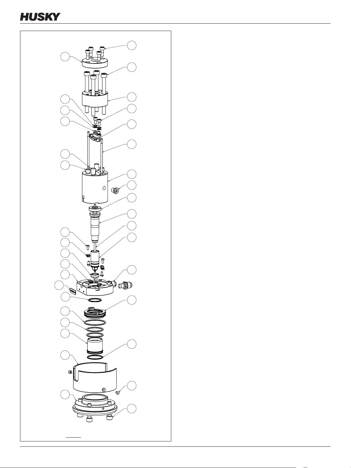
4. Remove the flexible air lines and air fittings
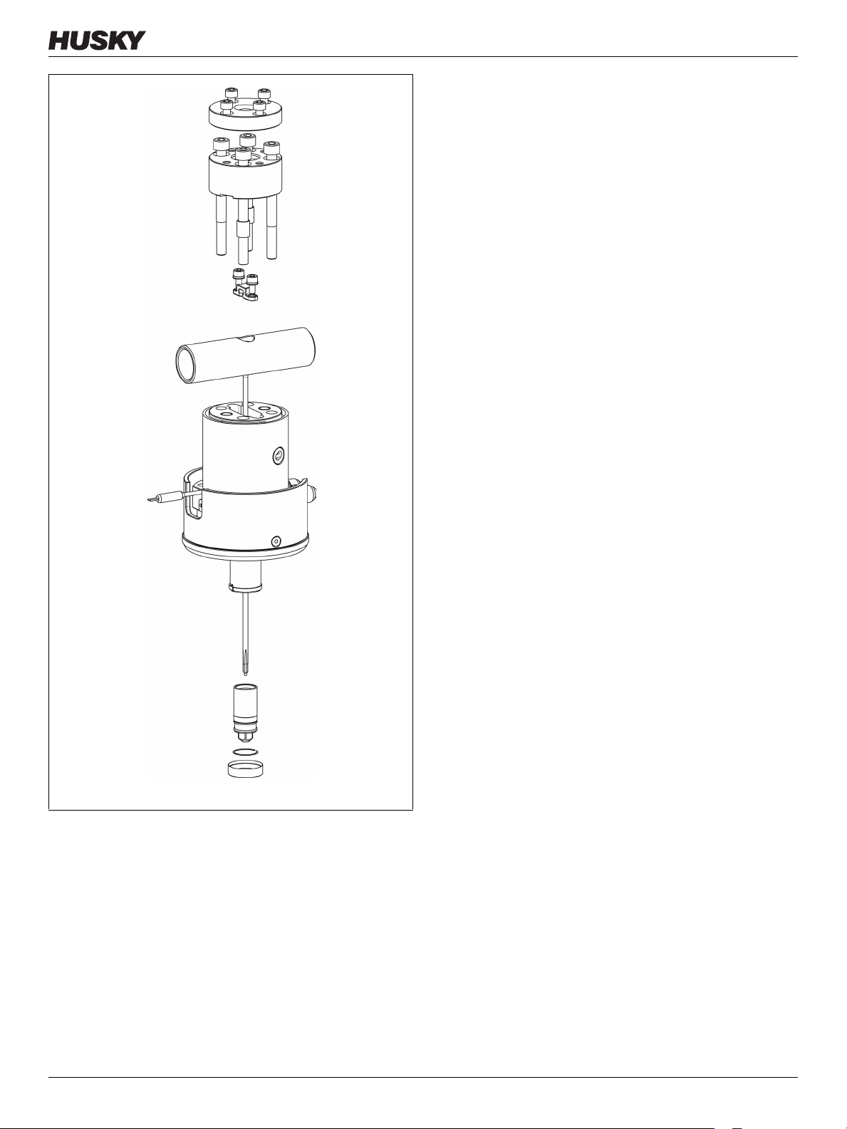
(Figure 1, item 20).
5. Loosen the four SHCS (item 13) securing the sprue
bushing insert (item 32) and remove them from the
extruder pad (item 31).
6. Loosen the four SHCS (item 14) securing the
extruder pad (item 31) and remove them from the
sprue body (item 27).
7. Loosen the two SHCS (item 9) securing the stem to
the stem retainer (item 29).
8. Remove the front ring from the nozzle heater (not
shown).
9. Remove the nozzle heater snap ring (not shown).
10. Remove the nozzle heater (not shown).
11. Loosen the nozzle tip (item 24).
Figure 1 U500 & U750 SCVG assembly (typical)
Service Procedure 521-0 3 of 21
12. Insert the valve stem removal tool (HPN: 3512615)
into the injection side of the sprue body.
13. Gently tap the valve stem removal tool ensuring
contact with the stem (item 45) at all times until the
stem is tapped free from the sprue body.
14. Loosen the two sprue body retainer tab SHCS (item
10) from the air plate (item 39).
15. Loosen the cylinder SHCS (item 11) securing the
cylinder (item 34) to the air plate (item 39).
16. Pull the valve stem slider (item 28) and piston rods
(item 41) out of the sprue body (item 27).
17. Pull off the cylinder insert (item 33) from the air
plate (item 39).
18. Disengage the piston rods (item 41) from the piston
(item 40).
Page 4

19. Pull the Melt Channel (M/C) reducer (item 36) out of
the air plate (item 39).
20. Pull the nozzle (item 23) out of the air plate (item
39).
21. Remove the weep fitting (item 25) from the sprue
body (item 27) to enable removal of the sprue body
heater (not shown).
22. Clean all parts after disassembly. Make sure the
sealing and contact surfaces are free of plastic,
grease, dirt, and dust.
23. Replace the Grafoil seals (item 22), piston seals
(items 18 & 19), cylinder insert seal (item 43), and air
plate seal (item 44) at each disassembly.
Service Procedure 521-0 4 of 21
Page 5
Seal Replacement
All seals should be replaced each time the unit is
disassembled to ensure optimal sealing. Seal life is rated
at 250,000 cycles or 6 months (whichever occurs first).
Husky recommends having a spare Preventative
Maintenance (PM) kit on hand to facilitate easy seal
replacement.
NOTE: The following PM kits are available:
• SCVG 500 PM kit (HPN: 3509935)
• SCVG 750 PM kit (HPN: 3509936)
• SCVG 1000 PM kit (HPN: 3509937)
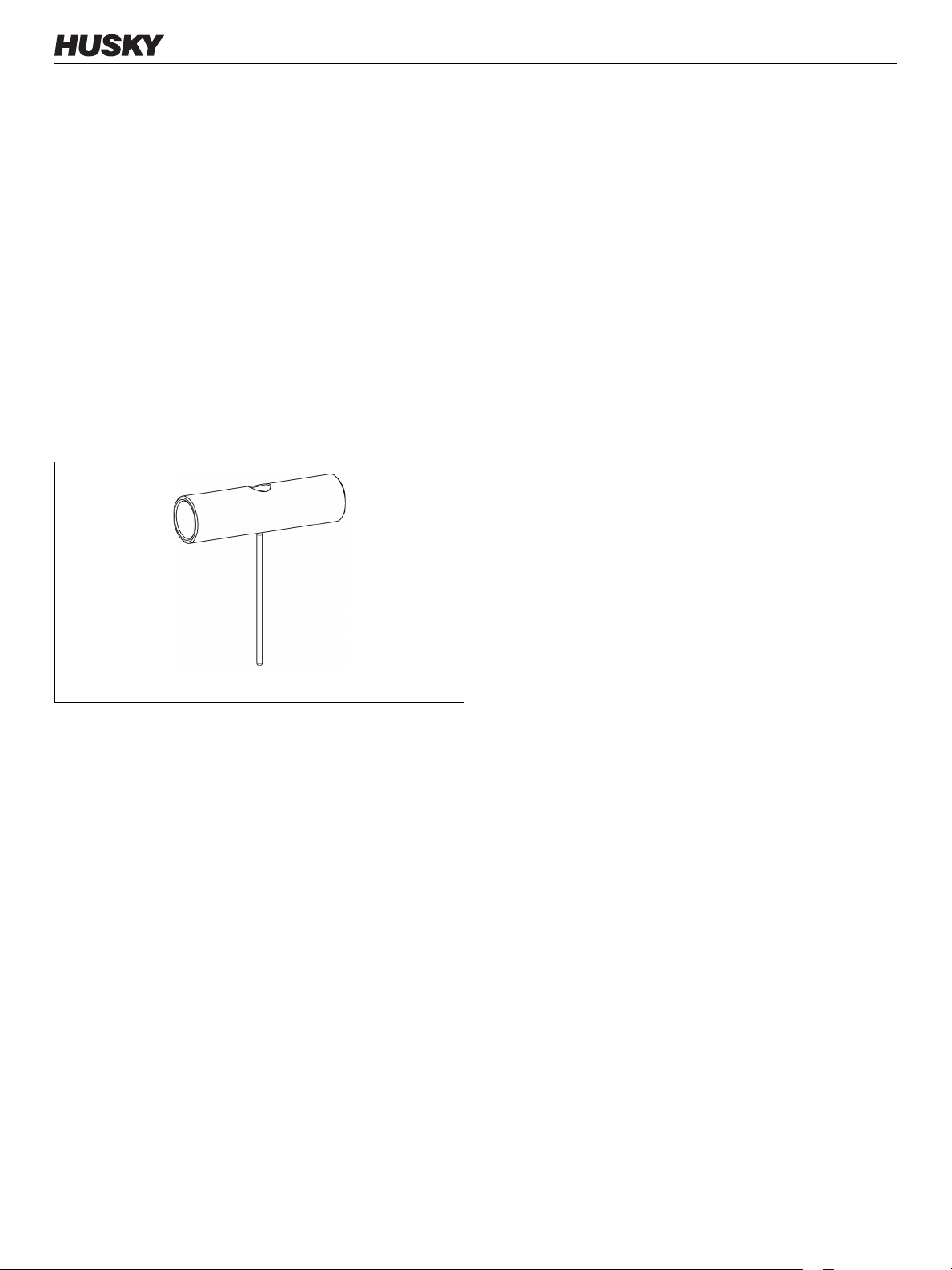
Stem Removal
1. Obtain a stem removal tool (Figure 2, HPN:
3512615).
Figure 2 Stem Removal Tool
Service Procedure 521-0 5 of 21
Page 6
2. Loosen the four SHCS securing the sprue bushing
insert and remove them from the extruder pad.
3. Loosen the four SHCS securing the extruder pad and
remove them from the sprue body.
4. Loosen the two SHCS securing the stem retainer to
the stem slider.
5. Remove the front ring of the nozzle heater.
6. Remove the nozzle heater snap ring.
7. Loosen the nozzle tip.
Figure 3 SCVG Assembly
Service Procedure 521-0 6 of 21
Page 7
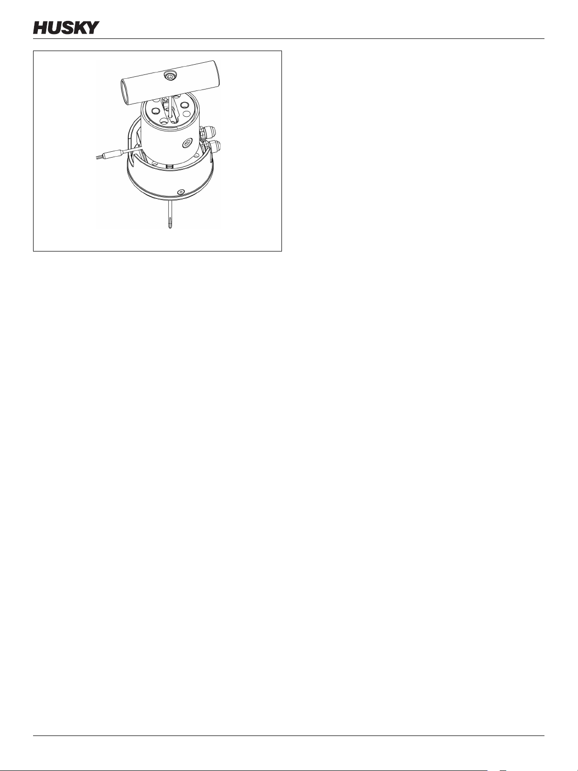
Figure 4 Inserting the Valve Stem Removal Tool
8. Insert the valve stem removal tool into the injection
side of the sprue body.
9. Gently tap the valve stem removal tool ensuring
contact with the stem at all times, until the stem is
freed from the sprue body.
Service Procedure 521-0 7 of 21
Page 8

Reassembly
1. Unpack and clean all of the components. Compare
the nozzle housing and valve stem to design prints
and BOM. Make sure that the sprue body and nozzle
housing melt channels are clean and free of burrs.
Compare all of the components to the assembly
drawing for proper items and quantity.
2. Attach the name plate to the air plate using the
supplied rivets.
3. Place the air plate in a vise (Figure 5) with the arrow
facing down (i.e. boss down/pocket up).
Figure 5 Air Plate
Figure 6 Air Plate
1. Housing Flats 2. Air Plate Slot
4. Insert the nozzle housing threads down into the
plate (Figure 6).
NOTE: The housing flats will engage the air plate
1
2
2
slot when fully seated.
1
Service Procedure 521-0 8 of 21
Page 9

1
2
Figure 7 Air Plate
1. Grafoil Air Seal 2. Air Plate 3. M/C Reducer
5. Install the Grafoil air seals (Figure 7, item 1) into the
air plate (item 2) and M/C reducer (item 3).
3
6. Install the sprue body retaining tabs (Figure 8, item
1) into the sprue body. Finger tighten into place.
1
1
2
1
Figure 8 Sprue Body
1. Sprue Body Retaining Tabs 2. Older Revisions without
Tab s
NOTE: Older revisions may not have tabs.
Service Procedure 521-0 9 of 21
Page 10

1
3
2
4
Figure 9 Sprue Body and Air Plate
1. Sprue Body 2. Air Plate 3. T/C Hole 4. T/C Groove
1
1
7. Place the sprue body (Figure 9, item 1) onto the air
plate (item 2). Make sure that the Thermocouple (T/
C) hole (item 3) on the sprue body lines up with the
air plate T/C groove (item 4, for the T/C wire leads).
NOTE: The Piston Rods may need to be moved into
alignment with the holes in the insulator to get
the insulator to seat against the sprue body.
8. Install the dowel bushings (Figure 10, item 1) into
the sprue body.
Figure 10 Sprue Body
1. Dowel Bushings
Figure 11 Sprue Body
1. Crush Rings
9. Install the crush rings (Figure 11, item 1) into the
sprue body.
1
Service Procedure 521-0 10 of 21
Page 11

10. Assemble the stem slider (Figure 12, item 1) and
connecting rods (item 2).
1
NOTE: The stem slider is assembled flat side down.
2
Figure 12 Stem Slider and Connecting Rods
1. Stem Slider 2. Connecting Rods
2
11. Tilt the sprue body 45 ° in vise as shown (Figure 13).
Figure 13 Tilting the Sprue Body
Service Procedure 521-0 11 of 21
Page 12

1
2
3
Figure 14 Valve Stem and Sprue Body
1. Nozzle Housing 2. Valve Stem 3. Stem head
4. Pocket
12. Install the valve stem (Figure 14, item 2) into the
nozzle housing (item 1) reverse taper side first, until
the reverse taper bottoms out on the sprue body
and the stem head (item 3) protrudes out of the
pocket (item 4).
4
1
2
Figure 15 Stem Retainer and Stem Head
1. Stem Retainer 2. Stem Head
13. Assemble the stem retainer (Figure 15, item 1) onto
the stem head (item 2) and seat it onto the stem
slider.
Service Procedure 521-0 12 of 21
Page 13

14. Apply anti-seize compound to the stem retainer
screws (Figure 16, item 2) and torque to 7lb-ft (9.49
Nm). Install a lock washer or star washer (item 1).
Make sure the valve stem assembly moves freely.
1
12
Figure 16 Stem Retainer Screws and Valve Stem Assembly
1. Lock Washer 2. Stem Retainer Screws
1
2
Figure 17 Extruder Pad and Sprue Body
1. Extruder Pad 2. Sprue Body
15. Install the extruder pad (Figure 17, item 1) onto the
sprue body (item 2). Make sure the assembly bolt
holes line up correctly.
Service Procedure 521-0 13 of 21
Page 14

1
Figure 18 Rotating the SCVG Assembly
1. Extruder Pad
16. Apply anti-seize compound to the extruder pad
(Figure 18, item 1) and sprue body SHCS. Install and
torque to 32 lb-ft (43.4 Nm).
17. Rotate the SCVG assembly 180 ° in a vise (Housing
up).
18. Install the piston o-rings (Figure 19, item 1) onto the
piston. Lubricate all o-rings with silicon o-ring
lubricant.
Figure 19 Piston O-Rings
1. Piston O-Rings
1
Figure 20 Piston
1. O-Rings 2. Cylinder Insert
1
19. Install the o-rings (Figure 20, item 1) onto the
cylinder insert (item 2). Lubricate all o-rings with
silicon o-ring lubricant.
2
Service Procedure 521-0 14 of 21
Page 15

1
2
Figure 21 Installing the O-Rings onto the Boss Plate
1. Piston O-Rings 2. Air Plate boss
20. Install the o-rings (Figure 21, item 1) onto the air
plate boss (item 2). Lubricate all o-rings with silicon
o-ring lubricant.
21. Install the cylinder insert (Figure 22, item 1) into the
piston. Make sure the cylinder insert does not cover
the inner connecting rod retaining groove.
2
1
Figure 22 Cylinder Insert
1. Cylinder Insert 2. Piston Rod Retaining Slots
1
2
NOTE: The chamfer side of the cylinder insert is
inserted opposite the piston rod retaining
slots (item 2).
22. Assemble the cylinder insert assembly (Figure 23,
item 1) onto the connecting rods (item 2).
2
Figure 23 Installing the Cylinder Insert
1. Cylinder Insert Assembly 2. Connecting Rods
Service Procedure 521-0 15 of 21
Page 16

1
2
3
4
Figure 24 Air Open Line Alignment
1. Cylinder Insert 2. Arrows 3. Air Open Lines 4. Air
Plate
1
1
23. Slide/push the cylinder insert (Figure 24, item 1)
down over the air plate boss o-ring.
24. Lubricate the cylinder inner walls with o-ring
lubricant and assemble onto the air plate (item 4).
Align the air open lines (item 3) by making sure the
arrows (item 2) are pointing to each other.
25. Apply anti-seize compound to the cylinder SHCS
(Figure 25, item 1) and install. Torque to 29 lb-ft (39.3
Nm) in a star pattern.
1
Figure 25 Cylinder SHCS
1. Cylinder SHCS
Figure 26 Air Test Fittings
1
26. Temporarily install the air test fittings (Figure 26)
and cycle the valve stem several times. Apply steady
pressure (110 psi/0.76 MPa) to air open and listen for
audible air leaks. Apply steady pressure (110 psi/
0.76 MPa) to air close and listen for any audible air
leaks.
NOTE: If there are any air leaks check for the
following:
• damaged o-rings
• partially seated components
• improperly torqued components
Service Procedure 521-0 16 of 21
Page 17

Figure 27 Nozzle Tip
1. Nozzle Tip
27. Install the nozzle tip (Figure 27, item 1) and torque
to specification (35-40 lb-ft/47.5-54.2 Nm).
1
28. Rotate the SCVG over 180 ° in a vise (sprue body
facing up).
29. Place/fit the sprue body T/C into the sprue body
(Figure 28, item 1) using small electrical pliers.
Remove the sprue body T/C (item 2) to facilitate
sleeve installation.
1
Figure 28 Sprue Body T/C
1. Sprue Body 2. Sprue Body T/C
2
Service Procedure 521-0 17 of 21
Page 18

30. Install the sleeve with the two M4 FHS (Figure 29,
item 1 - finger tighten).
Figure 29 Air Fittings
1. M4 FHS 2. Air Fittings
1
1
install.
12
31. Apply Teflon tape to the air fittings (item 2) and
32. Install the pre-fitted T/C (Figure 30, item 1) into
sprue body.
1
Figure 30 Sprue Body T/C
1. Pre-fitted T/C
1
Figure 31 Retainer Weep Fitting Hole
1. Weep Fitting Hole
33. Install the sprue body heater onto the sprue body.
Make sure the retainer weep fitting hole in the
heater (Figure 31, item 1) aligns with the sprue body
installation.
Service Procedure 521-0 18 of 21
Page 19

1
Figure 32 Retainer Weep Fitting
1. Heater Retainer/Weep Fitting
34. Install the heater retainer/weep fitting (Figure 32,
item 1) using an M6 Allen key.
35. Install the sprue bushing insert into the sprue body.
Make sure all four counterbores align with the sprue
1
body taps.
36. Apply anti-seize compound to the four M6 SHCS
(Figure 33, item 1) and install onto the sprue
bushing insert. Torque to specification per assembly
drawing.
Figure 33 Sprue Body
1. M6 SHCS
2
1
3
Figure 34 SCVG Assembly
1. Nozzle Heater 2. Snap Ring 3. Wire Leads
37. Rotate the SCVG assembly over 180 ° (nozzle facing
up).
38. Install the nozzle heater (Figure 34, item 1) and snap
ring (item 2). Make sure the wire leads (item 3) are in
the same orientation as the sprue body heater.
Service Procedure 521-0 19 of 21
Page 20

Figure 35 SCVG Assembly
1. Front Ring 2. Nozzle T/C
1
39. Install the nozzle T/C (Figure 35, item 2) and bend
1
the leads to avoid getting pinched between the
cavity plate and the manifold plate.
40. Install the front ring (item 1 - finger tighten).
2
41. Prepare the SCVG for shipment (Figure 36):
• Install the air fitting caps (item 3)
2
• Install the nozzle tip cap (item 2)
• Tie wrap the heater leads as shown (item 1)
3
Figure 36 Completed SCVG Assembly
1. Heater Leads 2. Nozzle Tip Cap 3. Air Fitting Caps
Service Procedure 521-0 20 of 21
Page 21

Table 1 HGT-50 Torque Specifications for SHCS
Sample Torque Chart
Torque
Size
Nm lb ft
M4 3 2.2
M5 6.2 4.6
M6 10 7
M8 25 18
M10 53 40
M12 95 70
M14 130 95
M16 220 160
M18 270 200
M20 390 290
M24 660 490
M30 1300 960
M36 2300 1700
• For a comprehensive listing of torque values for
other fasteners and fittings, refer to the Machine
Manual.
M42 3700 2700
M48 5500 4000
Further Assistance
If you require assistance, please call your Regional Husky
Sales Office or the respective Technical Support Group
listed below:
Bolton
Toll free: 1-800-465-HUSKY (4875)
Direct: (905) 951-4875
Fax: (905) 951-5348
Luxembourg
EC (except Greece): 008000 800 4300
Non-EC: + (352) 52115-4300
Fax: + (352) 523040
Service Procedure 521-0 21 of 21
 Loading...