

Page 1

SERIES 70 AND 1800
CONSUMER ELECTRIC PUMPS
INSTALLATION/OPERATION/PARTS
MANUAL
035219
REV. 0259
INSTALLERS - IMPORTANT
In addition to installation information, this manual contains warnings, safeguards
and procedures on the use and care of the Series 70 and 1800 pumps. Please leave
this manual with the pump owner after the installation is complete.
Copyright 1999 by Gasboy International, Inc. All rights reserved.
The information in this document is confidential and proprietary. No further disclosure shall be made without
permission from Gasboy International, Inc. Gasboy International, Inc. believes that the information in this document
is accurate and reliable. However, we assume no responsibility for its use, nor for any infringements of patents or
other rights of third parties resulting from its use. We reserve the right to make changes at any time without notice.
GASBOY INTERNATIONAL, INC. A TOKHEIM SUBSIDIARY LANSDALE, PA
Page 2

IMPORTANT WARNINGS AND SAFEGUARDS
Gasoline and petroleum products are flammable. To avoid injury or death to persons or damage to equipment or
property, follow these listed warnings and other warnings and precautions outlined in this manual when installing, using,
or working around this equipment. Check with GASBOY Technical Services for compatibility of liquids with pump
materials.
TURN OFF AND LOCK OUT ALL POWER TO PUMP BEFORE PERFORMING SERVICE, MAINTENANCE OR IN THE EVENT
OF A FUEL SPILL.
All products must be installed by a
qualified installer and used in
conformance with all building, fire, and
environmental codes and other safety
requirements applicable to its
installation and use, including, but not
limited to, NFPA 30, NFPA 30A, NFPA
395 & NFPA 70. A qualified installer is
familiar with fuel systems installations
under the above stated building, fire,
and environmental codes and other
safety requirements for the particular
type of installation.
This product is only part of a fuel
dispensing system and additional
equipment and accessories, such as,
but not limited to, breakaway
connectors, shear valves, pressure
regulators, flow limiters, and other
safety devices may be necessary to
meet the applicable codes.
For maximum safety, we recommend
that all employees be trained as to the
location and procedure for turning off
power to the entire system. Instructions
regarding proper operation of the
equipment along with the appropriate
safety warnings should be posted in
plain view at the fuel island.
Before performing service or
maintenance (including changing of fuel
filters or strainers) or in the event of a
fuel spill, turn off and lock out all power
to the system. In battery-powered
pumps, disconnect power source. In
submersible pump applications, turn off
and lock out power at the master panel
and close any impact valves to the
submersible pump and any other
dispensers which use that submersible
pump. AC power can feed back into a
shut-off dispenser when dispensers
share a common submersible pump or
starter relay. Also block islands so no
vehicles can pull up to the dispenser
when the dispenser is being worked on.
Federal DOT regulations prohibit
dispensing flammables, such as
gasoline, from portable tanks.
DO NOT
threads in the product.
DO NOT
pumping fuel or additives into aircraft.
DO NOT
direct fueling of aircraft without filters
and separators necessary to ensure
product purity.
DO NOT
required (for food products for human
consumption) or with water-based
liquids.
DO NOT
using the pump.
DO NOT
electrical equipment which may ignite
fumes.
DO NOT
gasoline or other petroleum products
into a vehicle with its motor running.
DO NOT
gasoline or other petroleum products
into unapproved containers or into
approved containers in or on vehicles
including trucks. All containers must be
filled on the ground to prevent static
discharge. Always use Approved and
Listed hoses and nozzles with electric
pumps and dispensers.
DO NOT
manner. Nozzles shall conform to UL
and NFPA code requirements for
attended or unattended service.
DO
with proper filters based on the product
being dispensed and its intended use.
DO
clothes when dispensing any liquid
which may be potentially harmful or
hazardous.
DO
clothing clear of belts, pulleys, and other
exposed moving parts at all times.
use Teflon tape for any pipe
use consumer pumps for
use commercial pumps for
use where sanitary design is
smoke near the pump or when
use near open flame or
permit the dispensing of
permit the dispensing of
block open the nozzle in any
ensure that the pump is equipped
wear safety goggles and protective
keep all parts of body and loose
DO
require washing and changing of
clothes if fuel is spilled on a person or
his/her clothing. Keep away from open
flames, sparks, or people smoking.
DO
provide a receptacle for catching
product from pump/meter when
servicing.
DO
clean up product spills on the
driveway. Turn off and lock out all
power prior to cleanup.
DO
insure pump is properly grounded.
DO
insure hose is compatible with fluid
being dispensed.
DO
inspect hose, nozzle, and pump on
a regular basis for wear, damage, or
other conditions which may create a
safety or environmental hazard.
DO
make sure all pipe threads are
properly cut and the inside reamed to
remove burrs. Use UL classified
gasoline-resisting compound on all
joints of gasoline handling piping.
Sealing compound must also be
resistant to Gasohol (Ethanol and
Methanol). Use gasoline-resistant pipe
compound on male threads only; pipe
compound used on female threads can
be squeezed into the supply line where
it can enter the product stream and
become lodged in the pump or meter.
DO
ensure that junction box covers are
in place and properly tightened. Mating
surfaces between the box and cover
must be free of dirt, nicks, and
scratches. All unused entries into the
junction box must be properly plugged.
035282 Rev. 0215
GASBOY INTERNATIONAL, INC.
A TOKHEIM SUBSIDIARY
707 North Valley Forge Rd. Lansdale, PA, 19446
(215) 855-4631
●
FAX: (215) 855-0341
●
Page 3

CONTENTS
IMPORTANT WARNINGS AND SAFEGUARDS FOR CONSUMER PUMPS
Section 1: INTRODUCTION
Purpose..................................................................................................... 1-1
Specifications* .......................................................................................... 1-1
Section 2: INSTALLATION
Installation Precautions............................................................................. 2-1
Supply Line - Underground Tanks............................................................ 2-2
Pump Dimensions - Series 70, Model 1820 ............................................. 2-3
Pump Dimensions - Series 1820R............................................................ 2-3
Installation Instructions ............................................................................. 2-4
Cabinet Removal for Installation or Service (Series
1820 only - Rounded Cabinet).......................................................... 2-4
Cabinet Removal for Installation or Service (Series
1820 only - Squared Cabinet)........................................................... 2-4
Installing Hose and Nozzle.................................................................. 2-4
Direct Mount on Underground Tank .................................................... 2-5
Direct Mount on Aboveground Tank.................................................... 2-6
Pedestal Mount Pump ......................................................................... 2-7
Wall Mount........................................................................................... 2-8
Vacuum Breaker.................................................................................. 2-9
Section 3: WIRING
Wiring Precautions.................................................................................... 3-1
Circuit Breakers ........................................................................................ 3-1
Grounding................................................................................................. 3-2
The Pump Motor....................................................................................... 3-2
Wire Size .................................................................................................. 3-2
Pulser Wiring ............................................................................................ 3-3
Conduit...................................................................................................... 3-3
Pump Wiring Diagrams............................................................................. 3-4
Section 4: STARTUP AND OPERATION
Pre-Startup Checklist................................................................................ 4-1
Startup ...................................................................................................... 4-1
Post Startup Tests .................................................................................... 4-2
Voltage................................................................................................. 4-2
Tightness............................................................................................. 4-2
Meter Calibration ................................................................................. 4-2
Strainer Cleaning................................................................................. 4-3
Daily Operation......................................................................................... 4-3
Section 5: MAINTENANCE AND TROUBLESHOOTING
Maintaining Trouble-Free Operation......................................................... 5-1
When Your Pump Needs Service............................................................. 5-2
0144 Contents-1
Page 4

GASBOY Series 70 & 1800
Troubleshooting........................................................................................ 5-3
Disassembly of Pump............................................................................... 5-5
Meter-Register Disassembly..................................................................... 5-5
1860 3-Wheel Register Service and Maintenance ................................... 5-6
4860 4-Wheel Register Service................................................................ 5-7
Section 6: PARTS
Series 70 Assembly.................................................................................. 6-2
Optional Accessories........................................................................... 6-3
Series 1800 Assembly.............................................................................. 6-4
Optional Accessories........................................................................... 6-5
Direct Drive Motor-Pump Assembly.......................................................... 6-6
Installation Parts ....................................................................................... 6-8
1860 and 4860 Meter-Register................................................................. 6-9
Register Assemblies................................................................................. 6-9
1860 3-Wheel Meter Register (Model 1820) ............................................ 6-10
4860 4-Wheel Register (Model 72S and Series 1820R) .......................... 6-12
Model 1820 Register Setback and Switch Linkage Assembly.................. 6-14
Optional Kits for Series 70 and 1800 Pumps............................................ 6-15
Series 1820R Parts List............................................................................ 6-16
1820R Pulser and Junction Box Assemblies............................................ 6-18
Warranty
Contents-2 0144
Page 5

Section 1
INTRODUCTION
PURPOSE
The GASBOY
provided to assist the installer in installing and operating the unit. Faulty installations are the
major cause of unit malfunc tions. This manual should be supplied to the electr ician prior to the
installation of conduit and wiring. The Series 70 or 1820 pum ps
as described in this manual. This manual also c ontains warnings, saf eguards and proc edures on
the use and care of the pump. Be sure to leave this manual with the pump owner after the
installation is complete.
Customers and installers having any questions pertaining to the installation should
☎☎☎☎
contact their GASBOY distributor.
Series 70 and 1820 Consumer Electric Pumps Installation/Operation Manual
must
be installed and operated
is
SPECIFICATIONS
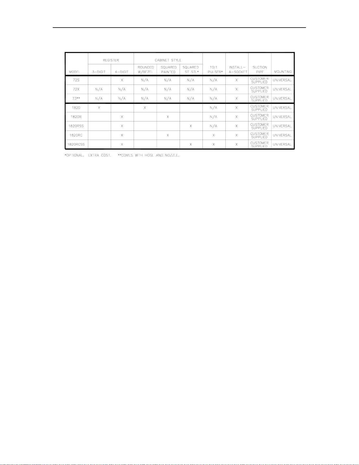
Series 70 and Series 1820 pumps are m ade specifically for private use on vented tank s. W hile
their outward appearance differs, they basically offer the sam e features. These pum ps can be
mounted on aboveground skid tank s, directly mounted above underground tank s, or mounted on
pedestals for remote underground installations. Table 1-1 summarizes the features for each
model.
Pumping Unit: Self-priming, direct-drive rotary vane; 23 PSI (1.6 bars) stainless steel bypass; check
valve with pressure relief valve.
Motor: 1/3 HP, 1725 RPM motor with thermal overload protection and auxiliary AC line.
Standard 115 VAC, 60 Hz; optional 230 VAC, 50 Hz. AC junction box included.
Register: 70: 4-wheel push-button reset, 7-digit master totalizer
1820: 3-wheel, volume only; lever-type reset with interlock; 6-digit master totalizer
(Optional, except for 1820R: 4-wheel push-button)
Registers show delivery in US gallons, Imperial gallons, or liters and change gears are
available to convert registers for unit of measure.
Meter: Nutating disk phenolic measuring chamber in aluminum die-cast housing; adjustable
calibration +.5% at full flow
Hose & Nozzle: 12' (3.66 m) UL-Listed hose assembly with integral static discharge wire; manual self-
closing nozzle.
Connections: 2" (5.08 cm) NPT for tank opening; 1" (2.54 cm) suction; 3/4" (1.91 cm) NPT discharge
Strainer: 100-mesh nylon
Delivery Rate: 18 GPM, at 115V, 60 Hz.; 60 LPM at 60 Hz.; 68 LPM at 50 Hz.
Finish: High-gloss red urethane or color of choice. 1820 only: Stainless steel extra cost option.
Approvals: UL, CSA
Additional extra cost options include: vapor rec overy, vacuum breaker return line, longer hoses,
hose breakaways, automatic nozzles, external filters, wall m ounting kits, and for Ser ies 1820 only,
10:1 pulser or rear- or side-mount filter kits.
9312 1-1
Page 6
GASBOY Series 70 & 1820
Table 1-1. Series 70 and 1820 Features
Stripped-down versions of Series 70 pumps, which mount on customer-supplied piping and
fittings, are available. Model 72X has no attachments or register, Model 73 has a hose and
nozzle, but no meter or register.
1-2 9312
Page 7

Section 2
INSTALLATION
INSTALLATION PRECAUTIONS
All tanks and installations m ust conform with all building/fire c odes, all Federal, State, and Local
codes, National Electrical Code, (NFPA 70), NFPA 30, Automotive and Marine Service Station
Code (NFPA 30A) and NFPA 395 codes and regulations.
Plan your installation carefully. Dispensing troubles, which seem to be pump-related, are
frequently traced to faulty installation. Review the following list of installation
to avoid potential problems:
DO's
and
DON'T's
DO
1.
2.
3.
4.
5.
6.
7.
8.
9.
read the
It contains important information regarding the safe use of your pumps.
DO
install an emergency power cutoff, if the pump is used for other than pers onal use. In
addition to circuit breaker requirements of NFPA 70 and NFPA 30A, a single c ontrol which
simultaneously removes AC power from all site dispensing equipment is recommended.
This control must be readily accessible, clearly labeled, and in accordance with all local
codes. In order to provide the highest level of saf ety, we recommend that all em ployees be
trained as to the location and procedure for turning off power to the dispensing equipment.
DO
use breakaway couplings on discharge hose. W hile not required for tanks under 1100
gallons, use is recommended for safety reasons.
DO
have the pump installed by a competent installer/electrician.
DO NOT
DO NOT
DO NOT
nipples, never close nipples).
DO NOT
DO NOT
crushed rock, or pea gravel).
WARNINGS
experiment with a pump if you are not sure the installation is correct.
overload sub- or main breaker panels.
install any underground piping without proper swing joints. (Always use shoulder
cover any lines until they have been both air- and liquid-tested.
back-fill the tank or supply line with cinders or ashes. (Back -fill with clean sand,
page at the front of this manual, preceding the Table of Contents .
DO NOT
10.
galvanized or fiberglass* pipe and fittings). *Install all fiberglass pipe and fittings acc or ding to
manufacturer's specifications and requirements.
DO NOT
11.
diagram or wire chart provided in Section 3).
DO NOT
12.
DO NOT
13.
DO NOT
14.
storage tank.
9312 2-1
use black iron pipe or fittings for underground installations. (Use only new
use power line wiring of inadequate capacity. (Use gauge specified by the wiring
use a circuit breaker of improper size. (See Section 3).
install fill pipe to tank where it can be submerged with standing water.
use the GASBOY fuel dispensing equipment to remove water ballast from the
Page 8

GASBOY Series 70 & 1820
DO NOT
15.
found around wires at all junction box entrances is a requirement of the National Elec trical
Code and should not be disturbed. Tighten junction box covers before replacing panels.
DO NOT
16.
wires should be run in threaded, rigid, metal conduit. All threaded connections must be
drawn up tight with five (5) threads minimum engagement. Only one opening in the AC
junction box is provided. At completion of the installation, it is the installer's res ponsibility to
ensure that any unused openings are plugged.
use gaskets on covers of explosion-proof type boxes. The sealing compound
use knock-out boxes or flexible conduit for installing this unit. All power and lighting
SUPPLY LINE - UNDERGROUND TANKS
If you are using an underground tank, pitch the tank away from s uction end. Horizontal runs of
suction line should slope down from the pump toward the tank. Do not exceed an equivalent lift of
12' for gasoline or 14' for diesel to the center line of the pumping unit, including f riction res istance
in the suction pipe.
The end of the suction pipe must be at least three inches from bottom of tank.
The tank or piping should not be located under traffic ar eas. Swing joints (two ells) will prevent
damage to piping due to frost heave or ground settlement.
Use nonhardening, gasoline-resistant pipe compound on male thr eads of all pipe joints for liquid
handling piping.
2-2 9312
Page 9
Installation
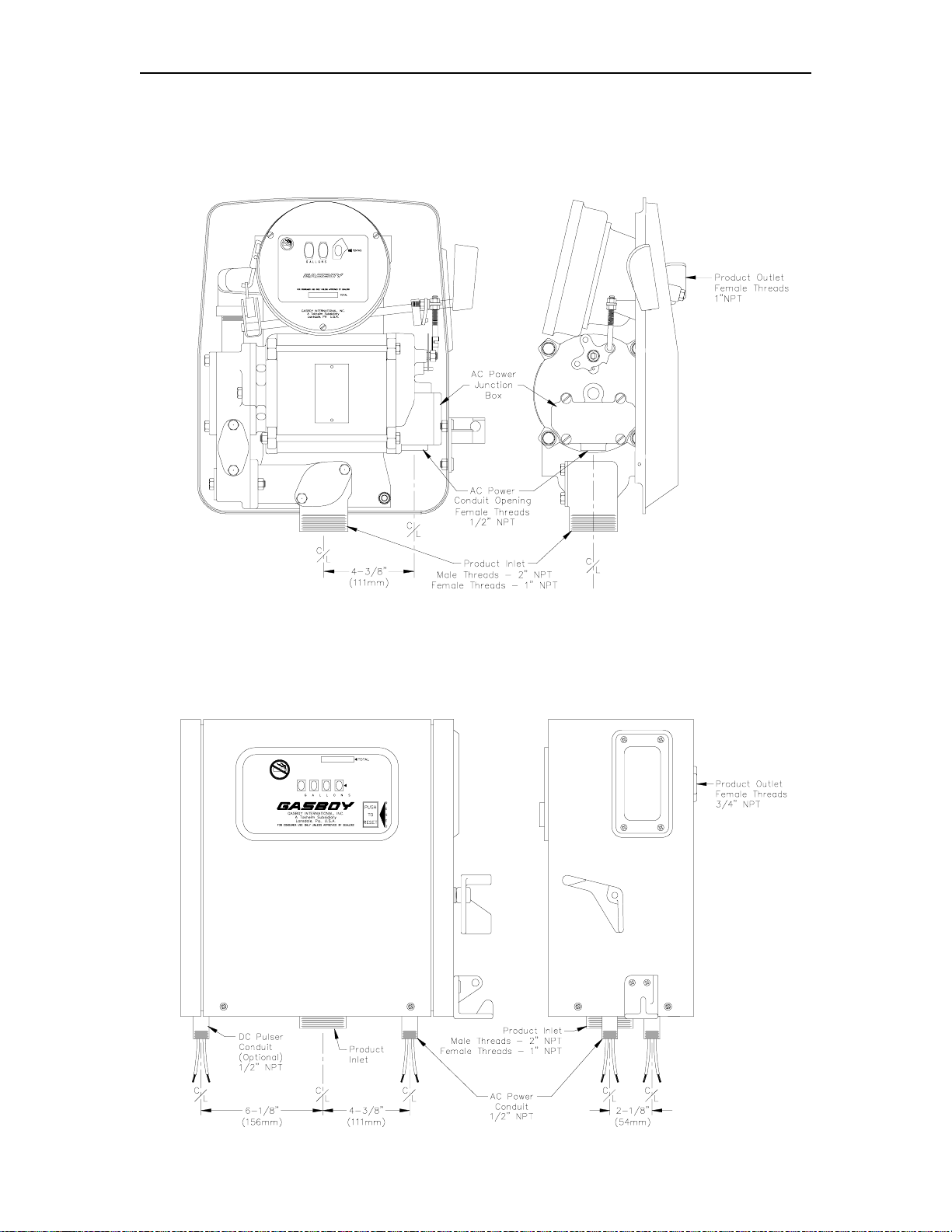
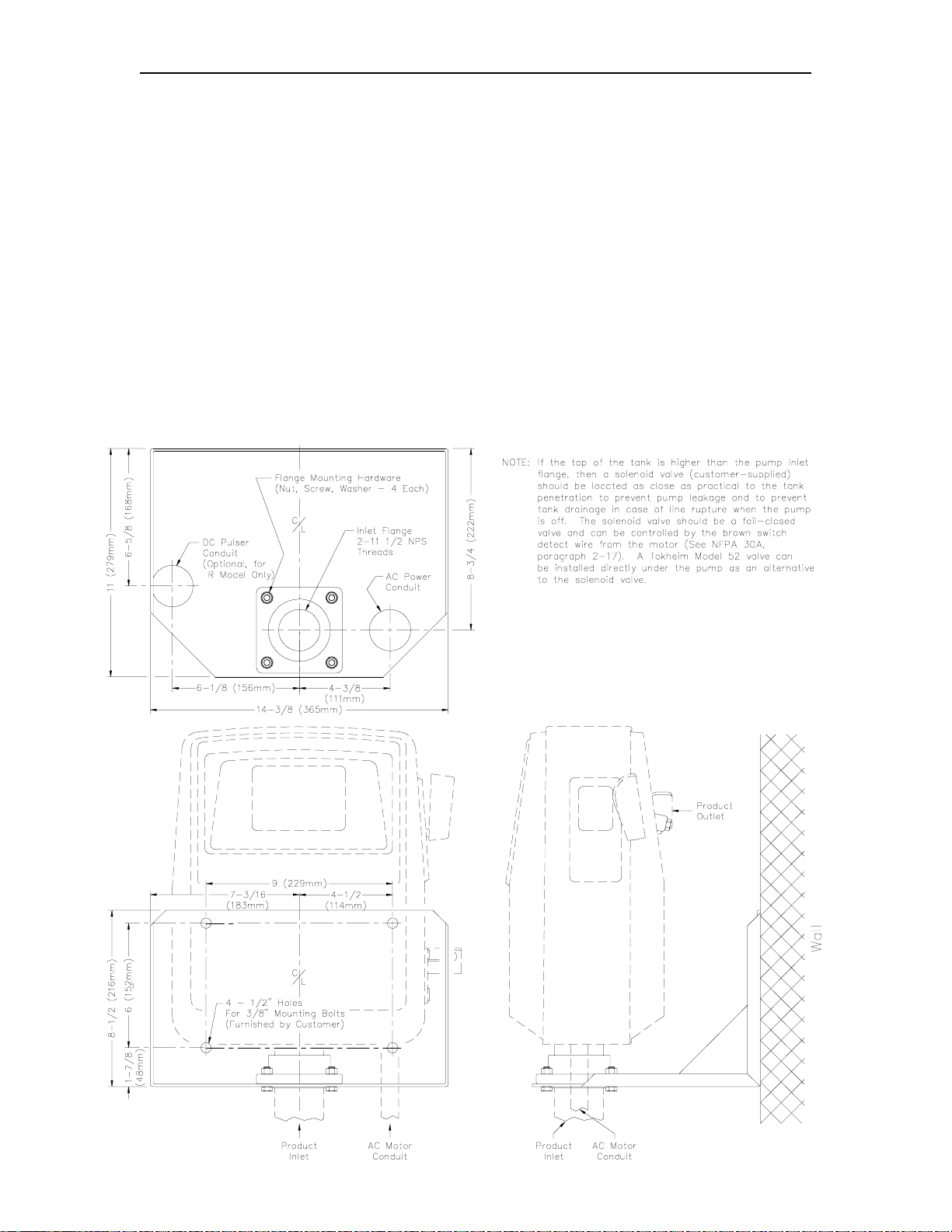
PUMP DIMENSIONS - SERIES 70, MODEL 1820
Pump diagrams shown are for Model 1820. Pump dimensions are the same for all Series 70
pumps.
PUMP DIMENSIONS - MODEL 1820R
Pump diagrams s hown are for Model 1820R. Pump dimensions are the same for these Model
1820 pumps: 1820R, 1820RSS, 1820RC, 1820RCSS.
9312 2-3
Page 10

GASBOY Series 70 & 1820
INSTALLATION INSTRUCTIONS
Cabinet Removal for Installation or Service (Series 1820 Only) - Rounded Cabinet
1. Remove two screws, one on each side of the cabinet.
2. Pull front panel assembly forward at bottom. As it clears the pumping unit, lift up to remove.
3. To replace front panel, engage pins at top in matching holes in rear panel. W ith front panel
assembly tilted back, pins m ay be seen through dial opening. Fr ont panel assembly will now
drop back into position.
4. Reinstall two screws in sides.
Cabinet Removal for Installation or Service (Series 1820R Only) - Squared Cabinet
1. Remove two screws on lower front of cabinet.
2. Remove two screws from upper back of cabinet.
3. Push in and hold the reset button and pivot the cabinet front panel upward until it clears the
button (Be careful not to damage the button). Remove panel.
4. For calibration or service, remove the lef thand side panel by unscrewing the two screws on
the bottom side of the cabinet.
5. To reassemble pum p cabinet, align s ide panel s cr ew holes with holes on base of c abinet and
screw tight. Replace the cabinet top and front panel by positioning the back plate and
pivoting the assembly forward. Be sure to press in the reset button until the front panel
clears it. Then replace the screws in the front and back of cabinet.
Installing Hose and Nozzle
To prevent undue stress and poss ible damage, install hos e and nozzle after installation of pump.
Hose must have static wire which provides electrical continuity between hose couplings to
dissipate static electrical charge.
1. Screw the pipe elbow (provided with the pump) into the product outlet on the back of the
pump. Apply gasoline-resistant pipe compound to male threads.
NOTE: Elbow fitting is not required, however, it provides strain relief for the hose.
2. Screw the hose into the open end of the elbow and tighten. Apply gasoline-resistant pipe
compound to male threads.
3. Screw nozzle onto hose.
NOTE: 1820R models are shipped with a vacuum breaker assembly (P/N 032701)
consisting of a tee, pipe nipple and vacuum breaker. This assembly should be
installed in the pump outlet before connecting the hose.
2-4 9312
Page 11
Installation
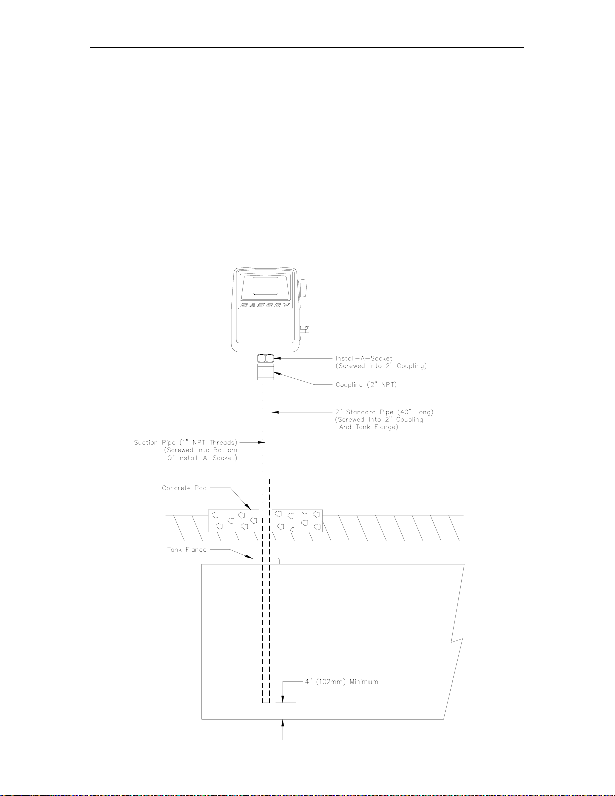
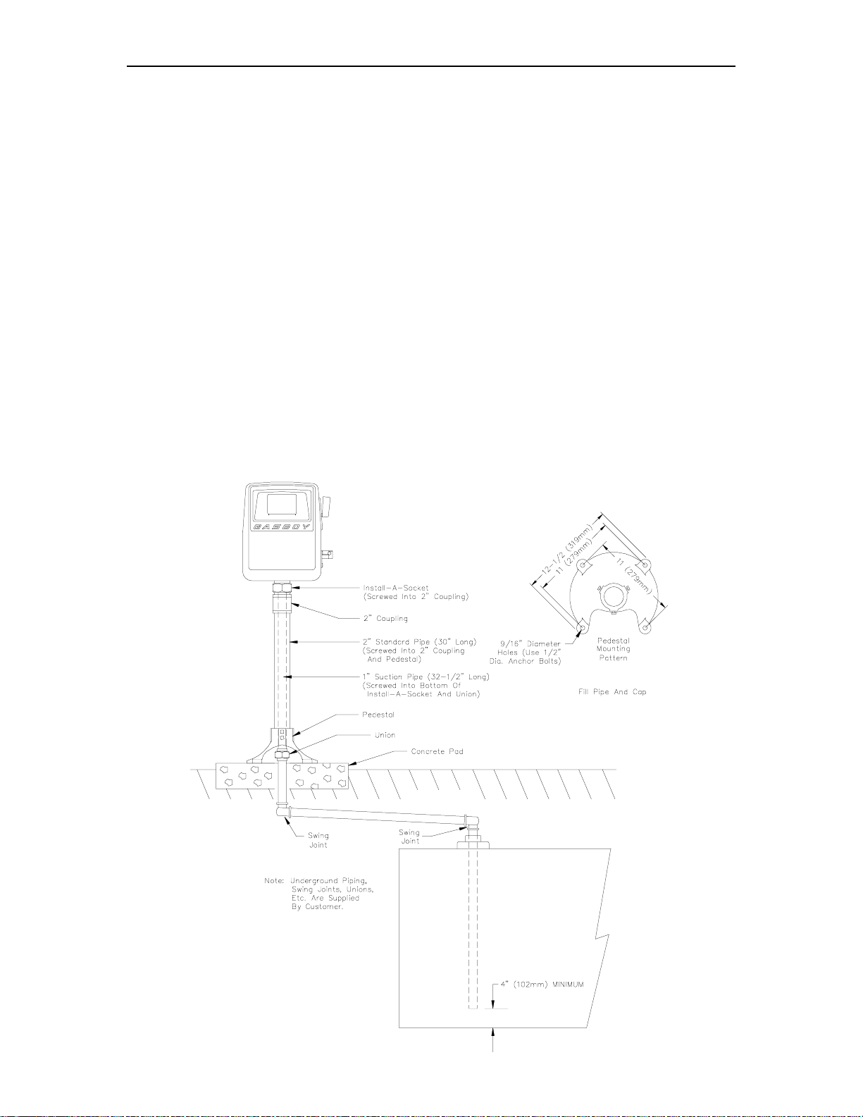
Direct Mount on Underground Tanks
1. Screw 2" coupling onto 2" standard pipe.
2. Screw 2" standard pipe into 2" tank flange. Apply compound to threads at bottom of base to
prevent surface water from entering the tank.
3. Screw 1" suction pipe into install-a-soc ket. Suction pipe should be long enough to allow 3"
clearance from bottom of tank. Apply gasoline-resistant pipe compound to male threads.
4. Lower 1" suction pipe through 2" standard pipe into tank. Tighten install-a-socket into
coupling at top of standard pipe.
5. Screw pump (2" threaded base) into ins tall-a-socket. This is a suction line connection and
must be tight. Apply gasoline-resistant pipe compound to male threads.
See the
Conduit
section for correct installation of electrical conduit.
9312 2-5
Page 12
GASBOY Series 70 & 1820
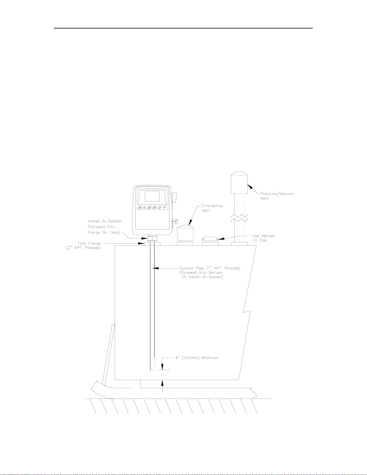
Direct Mount on Aboveground Tank
Aboveground tanks require both a pressure/vacuum vent and an emergency vent. The
pressure/vacuum vent r educes losses due to evaporation and is an air quality control m easure.
The emergency vent provides a relief from the pressur e resulting from heating and boiling of the
tank contents during a fire situation. Both vents must be properly sized for a given tank.
1. Screw 1" suction pipe into install-a-soc ket. Suction pipe should be long enough to allow 3"
clearance from bottom of tank. Apply gasoline-resistant pipe compound to male threads.
2. Screw install-a-socket directly into 2" flange in the aboveground tank.
3. Lift the pump to the height of the tank and tighten it into the install- a-sock et. Apply gasolineresistant pipe compound on male thread.
extended nozzle hanger, you may need to use a 2" coupling and close nipple in between the
pump and the install-a-socket. This will prevent interference of the hanger with the top of the
tank.
NOTE: If using an automatic nozzle with the
See the
Conduit
section for correct installation of electrical conduit.
NOTE: Aboveground tanks, located at commercial, industrial, governmental, or manufacturing
establishments and intended for fueling vehicles used with their busines s, cannot exceed
a capacity of 6000 gallons.
2-6 9312
Page 13
Installation
Pedestal Mount Pump
1. Screw 2" coupling onto threaded end of 2" standard pipe.
2. Slide cast iron pedestal base up over the unthreaded end of 2" standard pipe.
3. Screw 1" suction pipe into install-a-soc ket. Suction pipe should be long enough to allow 3"
clearance from bottom of tank. Apply gasoline-resistant pipe compound to male threads.
4. Insert 1" suction pipe into 2" pipe and screw install-a-socket into coupling on end of 2" pipe.
5. Assemble union onto lower end of 1" suction pipe conforming to your site's piping layout.
Note that the GASBOY base is provided with an opening on one side, so that an elbow can
be used and the suction brought out horizontally aboveground if desired, instead of straight
down through the island.
6. Slide base down to proper position at the lower end of the pedestal, tighten six set screws.
7. Screw the 2" male thread on the base of the pum p into the upper end of the install-a-soc ket.
Apply gasoline pipe compound to all male threads.
8. Securely mount pedestal base to concrete. If the pump is not securely fastened to the
foundation, supply line leaks at unions and pipe joints may occur.
See the
and swing joints are supplied by the customer. All metallic piping should be at least
Schedule 40 wrapped/coated black steel pipe with extra-heavy malleable iron screw type
fittings. Protect metallic piping in contact with the ground with a properly designed cathodic
protection system.
Conduit
section for correc t installation of electrical conduit. All under ground piping
9312 2-7
Page 14
GASBOY Series 70 & 1820
Wall Mount
The optional wall mount kit can be used with any Series 70 or 1820 pum p to be located rem ote
from the tank. The wall mount kit consists of a wall mounting bracket, pump mounting flange, and
hardware to attach the flange to the bracket. Hardware to attach the br acket to the wall is not
included.
1. Fasten mounting bracket to wall using appropriate 3/8" fasteners (customer supplied).
2. Screw mounting flange to pum p inlet. The flange with the four holes should be away from
the pump. Pipe thread compound is not required. Tighten flange and align parallel with
pump.
3. Bolt mounting flange to mounting bracket using the hardware supplied.
4. Remove the 1" plastic plug within the 2" pump bas e inlet and install the 1" inlet NPT inlet line
from the tank into the pump. Apply gasoline-resistant pipe compound to male threads.
Follow piping instructions shown on previous page for piping to the tank.
See the
Conduit
section for correct installation of electrical conduit.
2-8 9312
Page 15
Installation
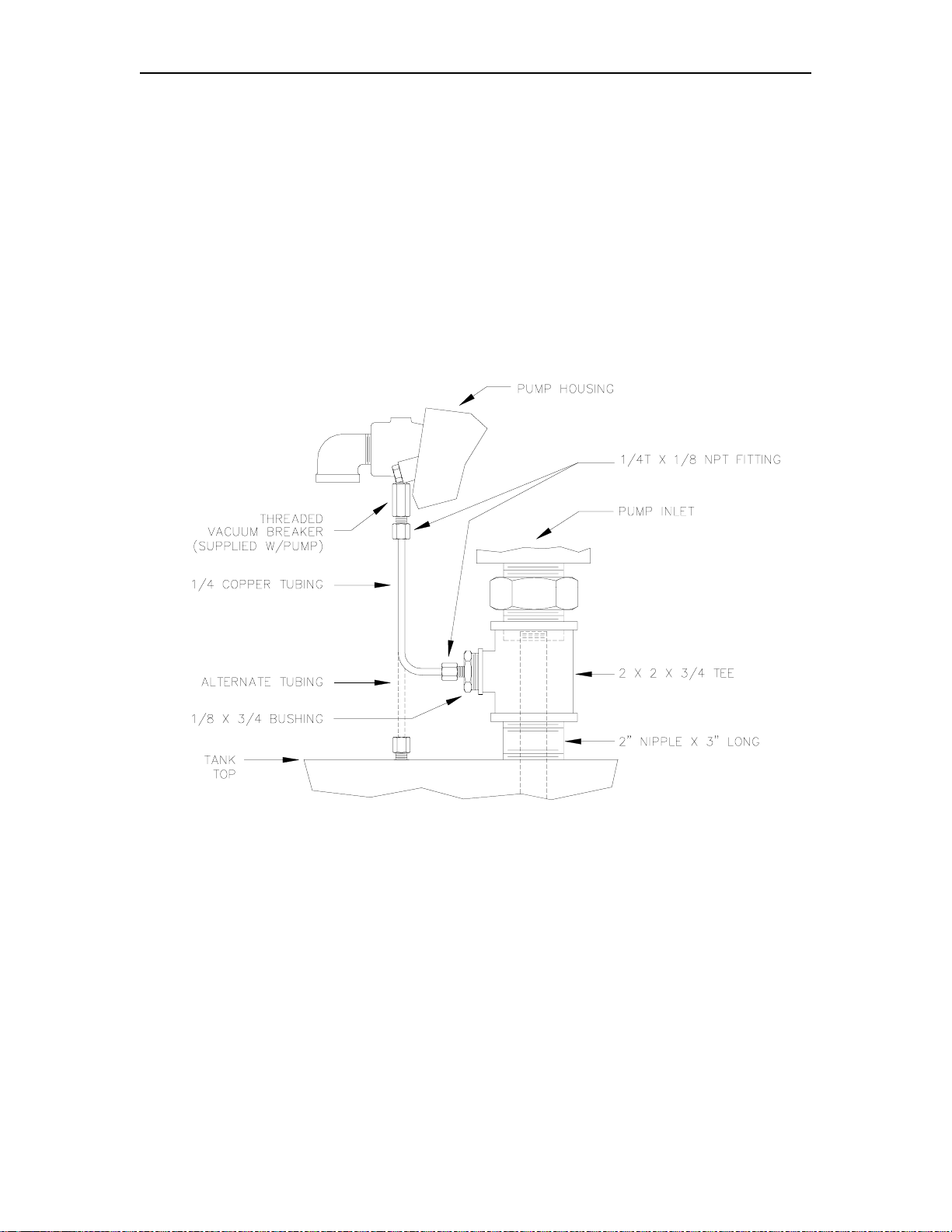
Vacuum Breaker
The vacuum breaker tubing kit can be used with any Series 70 or 1820 pump. The vacuum
breaker is used to break a s iphon s hould the nozzle drop below the fluid level in the tank while the
pump is stuck in the open position. A threaded vacuum break er, P/N 066570 is shipped installed
in the pump. GASBOY recommends that the vacuum breaker be tubed back to the tank.
The illustration below shows two methods for installing tubing for the vacuum breaker. In all
instances, the vacuum break er m ust be tubed (us ing 1/4" tubing) to the vapor spac e at the top of
the tank; if the tube is installed below the fluid level of the tank, the ability to break vacuum and
prevent siphoning will be lost. Using the illustrated m ethods, the tube end m ay terminate into the
annular vapor space between the 1" suction pipe and the 2" mounting pipe, or into an opening in
the top of the tank. All components shown are provided when you order the kit, P/N 032700.
NOTE: Tubing can be piped to any available opening on top of tank. Use reducer bushings
as required.
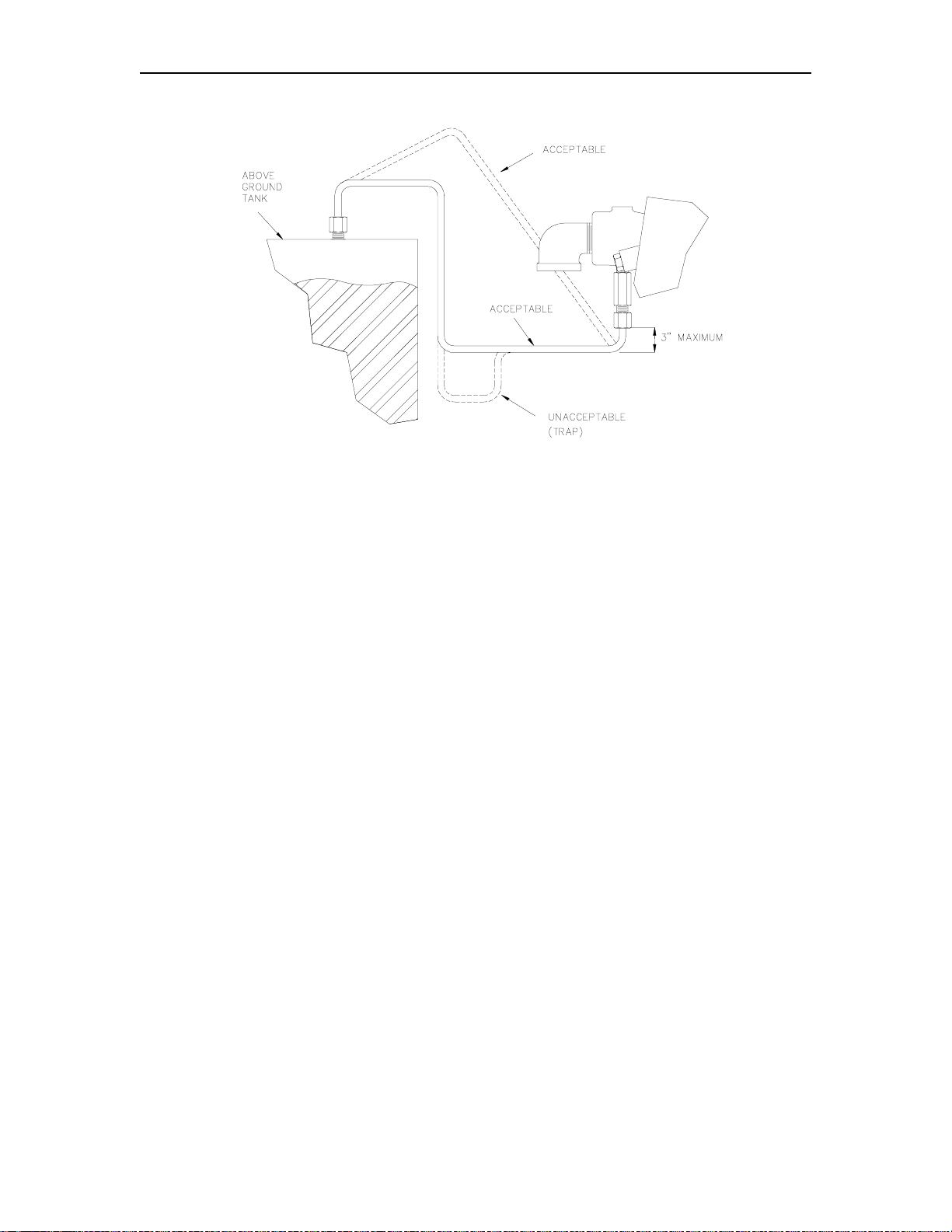
The illustration on the next page shows vacuum breaker tubing for inst allations where the pump is
installed below the fluid level of the tank. For these inst allations, the tubing must run directly to
the tank top. The tubing mus t be horizontal or must slope either toward the pum p or the tank s o
there are no traps or low spots. Traps or low spots can severely affect vacuum breaker
performance. Tubing length should not exceed eight feet.
9312 2-9
Page 16
GASBOY Series 70 & 1820
NOTE: Tubing can be piped to any available opening on top of tank. Use reducer bushings
as required.
Testing the Vacuum Breaker
1. Charge tubing completely with fluid.
2. Turn on pump and run for several minutes to purge any air from the system.
3. Turn off pump.
4. With nozzle at ground level and discharging into a container, open nozzle. A small quantity
of fluid (several cups) should drain and then stop.
2-10 9312
Page 17

Section 3
WIRING
WIRING PRECAUTIONS
The quality of the electrical installation is a m ajor factor in maintaining proper saf ety levels and
providing trouble-free operation of your GASBOY pum p. To assure a quality installation, follow
these rules:
1. Have the pump installed by a competent installer/electrician.
2. All wiring must be installed to conform with all building/fire codes, all Federal, State, and
Local codes, National Electrical Code, (NFPA 70), NFPA 30, Automotive and Marine Service
Station Code (NFPA 30A), and NFPA 395 codes and regulations.
3. Use only threaded, rigid, metal conduit.
4. Use only UL-approved insulated gasoline- and oil-resistant stranded copper wiring of the
proper size.
5. Wire connec tions should be tightly spliced and secured with a wire nut; close off the open
end of the wire nut with electrical tape.
6. The line to the motor should be on a s eparate circuit and installed on a 15 AMP breaker.
This should be sufficient for either 115V, 60 cycle or 230V, 50 cycle operation.
7. The unit must be properly grounded.
8. Install an emergency power cutoff if the pump is used for other than personal use. In
addition to circuit breaker requirements of NFPA 70 and NFPA 30A, a single c ontrol which
simultaneously removes AC power from all site dispensing equipment is recommended.
This control must be readily accessible, clearly labeled, and in accordance with all local
codes. In order to provide the highest level of saf ety, we recommend that all em ployees be
trained as to the location and procedure for turning off power.
9. When DC pulsers are used in the pump, the AC and DC wires must not shar e any conduits,
junction boxes, or troughs.
CIRCUIT BREAKERS
Power to the unit should be supplied from a dedicated 15 AMP circuit breaker. No other
equipment should be powered from this breaker. This motor draws the following current:
115VAC, 60 cycle, 5.1 amps; 230VAC, 50 cycle, 1.95 amps. If two (2) pum ps are supplied from
one breaker, that breaker must be capable of handling the load of both motors . Provisions must
be made to break both legs of any AC circuit.
9312 3-1
Page 18

GASBOY Series 70 & 1820
GROUNDING
To ensure proper operation of the equipm ent and provide the necessary safety factors, this unit
must be grounded. A ground wire (preferably green) m ust be connected between the unit's AC
junction box ground lug and the main electrical service panel. One (1) earth ground c onnection is
required per unit. The ground rod is to be a solid, corrosion-resistant conductor and must be
installed at the main electrical panel in ac cordanc e with the National Electric al Code. It should be
properly tied into the ground bus strip of the panel. W e recomm end the neutral and ground bus
strips be bonded together (unless prohibited by local codes).
THE PUMP MOTOR
Pumps are shipped from the factory with motors wired for either 115VAC, 60 cycle, or 230VAC,
50 cycle.
The pump motor is equipped with therm al overload protection. If overheated, it will shut itself off
without any damage to the windings. Be sure to turn off the pum p power if this occ urs. As the
motor cools, it will start without warning if power is on.
WIRE SIZE
The AC wire size of the AC power lines of a pump depends on the voltage at which the pump will
be operated (115/230) and the distance from the circuit breaker panel to the pump. W hen two
pumps are powered from the same breaker through the same wires, the gauge of the wires
should be increased to handle the added load according to the distance from the breaker panel.
Use the chart below to select the proper wire size for your installation.
Table 3-1. Wire Size
WIRE GAUGE SIZES FOR 1/3 HP MOTOR
DISTANCE
(FEET/METERS)
25’ 7m 14 14
50’ 15m 14 14
100’ 30m 12 12
150’ 46m 10 12
200’ 61m 8 12
250’ 76m 8 12
300’ 91m 8 12
115 VAC
GAUGE
230 VAC
GAUGE
The AC wire size for the reset complete (switch detect) line should be 14 AWG (when it is used).
3-2 9312
Page 19

Wiring
PULSER WIRING
An optional pulser (available on the Series 1820R only) is used when external monitoring of the
dispensing unit operation is desired. The puls er transmits one electrical signal (pulse) for each
predetermined amount of fuel dispensed. Reed 10:1 pulsers operating with DC voltages are
used. Pulser wiring must be 18AW G and ins talled in metal conduit separate from all AC wiring. It
cannot share a common junction box, wiring trough or conduit with any AC wiring.
CONDUIT
All wiring to the GASBOY pump must be installed in 1/2" threaded, rigid, metal conduit.
not use knockout boxes and flexible conduit.
If equipped with a DC pulser, AC power wires must be installed in a separ ate c onduit f r om the DC
pulser and the AC power wires and DC pulser wires must not be run in any sort of common
conduit or trough.
All wiring and conduit runs must also conform with the National Electrical Code (NFPA 70) and the
Automotive and Marine Service Station Code (NFPA 30A). All wiring and conduit runs must
conform to local codes.
The conduit layout drawing on the left is for all Series 70 and 1820 rounded c abinet models. The
drawing on the right is for 1820R models. The junction boxes shown below the 1820R are
supplied with the pump.
Do
9312 3-3
Page 20

GASBOY Series 70 & 1820
PUMP WIRING DIAGRAMS
115VAC Pumps Series 70 and 1820 (left) and Series 1820R (right)
230VAC Pumps Series 70 and 1820 (left) and Series 1820R (right)
NOTE FOR 230V MOTORS: Some motors may contain different wire colors than those shown. In
this case, Hot is Black, Neutral is White and Aux AC Control is Brown.
1. All wiring and conduit runs must conform with all building/fire codes, all Federal, State, and Local
codes, National Electrical Code, (NFPA 70), NFPA 30, Automotive and Marine Service Station Code
(NFPA 30A), and NFPA 395 codes and regulations.
2. For the Series 70 and Series 1820 rounded cabinet models, make the field wire connections in the
motor junction box. The 1820R models with the squared cabinet come with the wires already
extended through the end of a factory-installed conduit. The 1820R models also come with a junction
box which is to be mounted directly beneath the pump. The field wire connections for the 1820R
models should be made in this junction box (not the pump motor junction box). Wire connections
should be tightly spliced and secured with a wire nut. Close off the end of the wire nut with electrical
tape.
3. The Aux AC Control Lead wire is shipped capped from the factory. When used, it connects to a
solenoid valve or fuel management system. Do not connect this wire without first checking the ON
voltage of this line to ascertain compatibility with the equipment being connected.
4. Pulser wiring must be 18AWG and installed in metal conduit separate from all AC wiring. It cannot
share a common junction box, wiring trough or conduit with any AC wiring.
3-4 9312
Page 21

Section 4
STARTUP AND OPERATION
PRE-STARTUP CHECKLIST
The information below should be reviewed to help verif y the proper installation of your GASBOY
pump.
Local codes and requirements, correct the problem before powering on the unit.
1. The unit must be properly secured.
If the installation does not meet criteria listed, as well as any Federal, State, and
2. All plumbing must be c omplete and tight.
leaks
.
3. When DC pulsers are used in the pump, the AC and DC wires must not shar e any conduits,
junction boxes, or troughs.
4. All conduit work must be c omplete. All j unction box covers mus t be s ecured. Conduit seals
should not be sealed until the wiring is verified through proper operation.
5. The unit must be properly grounded.
6. Before any testing begins, remove any water in the tank through a fill opening, using a
suitable pump. Do not use the GASBOY pump to remove water. Serious damage may
occur.
7. A sufficient volume of fuel m ust be put in the tank to insu re that the liquid level is above the
bottom of the suction pipe.
8. Before placing nozzle into service, apply a few drops of light ma chine oil (s uch as 3- in-1) on
the stem. Operate the lever several times so that the oil penetrates the packing. This offsets
the drying action of gasoline and keeps the packing soft and pliable.
All liquid-carrying lines must be checked for
STARTUP
After successf ully verifying the installation against the completion check list, the unit is ready for
startup. Follow the procedure listed below to perform an orderly start-up.
1. Turn on the circuit breaker for the pump.
2. Remove the nozzle from the boot and turn on the pump handle.
3. If your model has an automatic res et, verify that the register resets to zeros. If your model
has a reset button, push it to zero the register.
4. Dispense fuel. Check all plumbing for leaks at this time.
5. Turn the pump handle off . Open the nozzle. No fuel should be dispens ed. The amount
delivered should be displayed on the register. If an optional pulser k it is attached, it will be
supplying pulses which may be recorded by an external monitoring system.
6. Repeat Steps 2 through 5 several times to ensure that the pump is operating satisfactorily.
9312 4-1
Page 22

GASBOY Series 70 & 1820
POST-STARTUP TESTS
Voltage
The incoming voltage to the pump should be checked and any reading not within 10% of rated
voltage should be corrected before tes ting is continued. When dealing with suction pum ps it is
good practice to take voltage readings while the suc tion pump is operating on bypass (turned on
but not dispensing product) and also while making a delivery. Any voltage drop in excess of 10%
during either of these operating states should be considered a low voltage condition. Corrective
action should be taken to insure an adequate power supply to the pump.
Tightness
After determining that the pum p is operating satisfactorily and the system is fully primed, check
the pump and piping to make sure that all connections are tight. W e recommend that the tank
and all piping not be covered until this has been completed.
Meter Calibration
NOTE: This meter was redesigned causing the calibration procedure to be different depending
on the age of your meter. Meters made after May 10,1995 are referred to as new style
meters; meters made before that date are referred to as old style.
All GASBOY pumps are adjusted for acc urate measure for gasoline within + .05 gallons at the
factory. However, since the conditions of the installation can affect pump accuracy, it is the
responsibility of the installer to check the pump for accuracy and make any needed adjustm ents.
Where required
Measures officials for their inspection before the unit is put into service.
, it is the owner's responsibility to report this device to the local Weights and
Choose the flow rate at which the meter will be used most often for the zero calibr ation point. For
example, if the pump is being used with an automatic nozzle, calibrate with the nozzle set on the
middle or top notch position, whichever is used most frequently.
Use a certified five-gallon measure with a sight glass and scale showing cubic inches over or
under an exact five gallons. Fill and drain the test measure to completely wet the interior
surfaces. Reset the register to zero and deliver an exact measured five gallons into the test
measure at the selected flow. Read the level of the liquid in the sight glass on the scale in + cubic
inches.
Follow the instructions in Section 3,
Installation or Service
narrow blade screw driver to turn the adj usting sc rew clock wise
to correct for plus cubic inches or counterclockwise for minus
cubic inches in the test measure.
Count the number of full turns and fr actional turns each tim e f or
reference in judging the num ber and direction of any additional
turns required to calibrate the meter to exact zero.
For new style meters, start with the screw turned all the way in
clockwise. For gasoline calibration, turn the screw
approximately two full turns counter-cloc kwise. For diesel, turn
the screw approximately two full turns counter-clockwise.
Replace the cap screw (old style only). Deliver about 1/2 gallon through the meter before res etting
to zero and retesting. Allow a ten second drain period each tim e the test measure is em ptied to
assure accurate measure. Adjust and retest until register is zeroed at desired flow.
to access the calibration screw. Use a
Cabinet Removal for
Strainer Cleaning
4-2 9312
Page 23

Start-Up and Operation
Clean the strainer immediately after the pump has been installed and tested, and again after a few
hundred gallons have been delivered. Thereafter, once every six m onths, or as required. The
procedure for cleaning the stainer can be found in the
section.
Maintenance and Troubleshooting
DAILY OPERATION
1. To begin fueling, remove the nozzle from the boot and turn on the pump handle.
2. If your model has an automatic reset, the register resets to zeros. If your model has a reset
button, push it to zero the register.
3. Dispense fuel.
4. Turn the pump handle off. The amount delivered is displayed on the register.
9312 4-3
Page 24

Page 25

Section 5
MAINTENANCE AND TROUBLESHOOTING
MAINTAINING TROUBLE-FREE OPERATION
Operating your pump with reasonable care will prolong its life and provide better service.
GASBOY pumps are designed and built to provide years of uninterrupted service; however,
certain parts of a pump ar e bound to wear. To keep your pump running at m aximum efficiency,
GASBOY recommends a periodic inspection at least twice a year.
Remove Water from Tank.
●
accumulate in both underground and aboveground storage tanks due to condensation or
defective fill openings that are not properly protected with watertight covers. Remove any
water with a sump pump to fores tall serious damage to equipm ent. Water, s ediment, and
other foreign matter that acc umulates in the tank can be drawn up into the pump and cause
failures.
Clean the Dial Face.
●
Preserve the Pump's Finish.
●
urethane paint. To preserve this finish, thoroughly clean all painted surfaces at regular
intervals with a high grade automobile polish and protect with a coat of paste wax. Do not
use abrasive cleaners or polish. Do not use high-pressure spraying equipment.
Stainless steel cabinets also requir e regular cleaning, especially in corrosive environments
such as coastal areas. Wash with mild detergent or soap and water followed by a clean
water rinse. Avoid abrasive cleaners which may scratch the f inish. Stubborn s tains, s uch as
oil or grease will require a stronger cleaner.
particles may adhere to the surface and cause corrosion. Always clean in the direction of the
polishing lines in the steel, never across them. In hard water areas, wipe the surface dry with
a soft clean cloth to prevent spotting. Protect the finish with a coat of paste wax.
Check and Change Filter.
●
intervals. A dirty filter in a pump will cause a slower delivery rate.
Clean the Strainer.
●
tested, and again after a few hundred gallons have been delivered. Thereafter, once every
six months, or as requir ed. The symptom s of a dirty or clogged s trainer in a pump are slow
delivery, noisy operation, and pulsation.
Use a soft, clean, damp cloth as needed.
Clean the strainer imm ediately after the pump has been installed and
After every fill-up, check your tanks for water. Water can
GASBOY pump housings are finished with a coating of
DO NOT
If the unit is equipped with a filter, check and change it at r egular
use ordinary steel wool as iron
To clean the strainer, turn off AC power to the pump. Locate the Suction Strainer Cap on the
plumbing unit and unscrew it to access and remove the strainer. Use compressed air to blow
the dirt out of the strainer. Always wear protective safety goggles or glasses when using
compressed air.
Clean the Bypass Assembly.
●
cleaning and should be checked if there is notable loss in system performance. No
adjustment is required. T o remove the valve, turn of f AC power to the unit, rem ove the two
bolts to the bypass cover and lift out the bypass valve assembly.
0144 5-1
The bypass valve assembly should be removed only for
Page 26

GASBOY Series 70 & 1820
WHEN YOUR PUMP NEEDS SERVICE
When your pump needs service, follow these guidelines:
Procedures requiring disassembly of portions of the pump should be performed by
●
competent service personnel. GASBOY has a distributor network which services fuel
dispensing equipment in every part of the country.
Turn off all power to t he pump to reduce the risk of electrical shock w hen servicing
●
(including changing o f fuel filters or st rainers). Also block islands so no v ehicles can
pull up to the pump when it is being worked on.
Replace worn, rusted, or corroded parts immediately with new authorized service parts
●
supplied by GASBOY. Replacing parts with incorrect or substandard subs titutes will result in
unsatisfactory pump operation. Always use new gaskets or seals when servicing or
rebuilding Gasboy equipment; do not re-use old ones. Using authorized parts will insure the
continuity of the Underwriters' Label on your pump.
Section 6 lists parts and service procedures f or the Series 70 and 1820 pumps. Using par t
numbers when ordering will expedite your order and reduce the possiblility of the wrong par ts
being shipped.
The remainder of this section contains troubleshooting information and assembly/disassembly
procedures for various components that may need service.
5-2 0144
Page 27

Service and Troubleshooting
TROUBLESHOOTING
If problems are encounter ed in operation of the pum p, follow the pr ocedures below in an attempt
to isolate the problem. W hen the problem is detected, follow the proc edures for disassem bly of
the pump.
Pump Won't Start
Is the breaker at the panel turned on?
✓✓✓✓
Is the Aux AC Control wire capped or connected to a solenoid valve or fuel management system?
✓✓✓✓
Is there power at pump? Check at junction box. Voltage cannot be below 104 volts on a 115V pump;
✓✓✓✓
204 on a 230V pump.
Is switch rod turning the switch on and off at the motor?
✓✓✓✓
Is motor overheated (thermal switch cutoff)? Be careful, the external motor surface could be hot
✓✓✓✓
enough to be painful or cause injury. Let cool and re-try.
!
Replace motor if above checks do not solve the problem.
Pump hums but won't start.
Is voltage adequate? Check voltage with pump on bypass with nozzle closed. Voltage cannot be
✓✓✓✓
below 104 volts on a 115V pump; 204 on a 230V pump.
Is the Aux AC Control wire is capped or connected to a solenoid valve or fuel management system?
✓✓✓✓
Check rotor, vanes, and bypass valve for free operation. Check motor with rotor and vanes removed;
✓✓✓✓
shaft should turn easily and smoothly by hand. Spin shaft by hand clockwise,
(hand clear of shaft) and observe shaft - shaft should stop clockwise
counterclockwise direction; if it does not, replace motor.
quickly start motor
motion and turn in a
!
Replace motor if above checks do not solve the problem.
Pump runs but won't prime or deliver product.
Is there gas in tank?
✓✓✓✓
Do you have a nozzle with the anti-drain valve removed? (Must be able to blow air through the nozzle
✓✓✓✓
in the direction the fuel flows through it when the nozzle handle is held open.)
038519 for unleaded and 038520 for diesel.
Loosen pump cover and slide aside so you can observe the rotor and vane movement inside the
✓✓✓✓
pump cavity. Rotor should be turning freely in a counter-clockwise motion. If rotor turns
motor is bad.
If register is recording but no product is being dispensed, you may have a supply line air leak.
✓✓✓✓
Check for an air leak on suction side of pump. Is check valve seated properly? Reassemble and
✓✓✓✓
prime pump using liberal quantity of motor oil in pump cavity; if it primes, run pump full
nozzle closed; shut off motor and check for leak on suction side of pump
observed liquid leakage would indicate an air leak when pump is
prevent priming when pump was empty.
Are bypass, strainer, and check valve cover plates flat? They could be bent from excessive pressure
✓✓✓✓
created by a vehicle running over the hose.
Is there an air leak in the suction line below check valve. Make accuracy check using 5 gal Seraphim
✓✓✓✓
test can. Any clock fast error (see
the suction line. The most common source of an air leak in the
for alignment and tightness before checking balance
suction line is blocked or has a severe air
Inaccurate Delivery
of suction line. If pump does not prime using oil,
leak.
) in excess of 2-1/2%
running with nozzle open and would
suction line is the union - check union
Use GASBOY P/N
flow and snap
above check valve. Any
indicates an air leak in
clockwise,
0144 5-3
Page 28

GASBOY Series 70 & 1820
Pump delivers product but won't register.
Is main totalizer recording? If yes, problem is in register assembly. Check to be sure the lever on the
✓✓✓✓
side of the register is returning back to the record position.
If the main totalizer is not working, the problem is a broken or jammed measuring chamber.
✓✓✓✓
Pump delivery is slow.
Check for dirty strainer.
✓✓✓✓
If pump has a filter, change filter.
✓✓✓✓
An automatic nozzle will reduce flow rate about 25%. Check flow rate without nozzle or with standard
✓✓✓✓
nozzle. A farm type automatic nozzle (such as Husky 1GS swivel) provides the
Check for supply line restriction by testing the pump with a vacuum gauge. If vacuum is abnormally
✓✓✓✓
high, there is a restriction.
best flow.
Pump loses prime.
Inspect check valve poppet and seat for clean mating surfaces.
✓✓✓✓
If, after a period of non-use, a pump delivers product initially, followed by air and then full flow, there is
✓✓✓✓
an air leak in the suction line.
Install pressure gauge between hose and nozzle. Operate pump at full flow. Snap nozzle closed and
✓✓✓✓
turn off pump. If pressure falls to zero rapidly, replace check valve and clean
and inspect valve seat.
Inaccurate delivery.
Calibrate the meter (See Section 4).
✓✓✓✓
A clock-fast error (more on the register than is delivered) in excess of 2 1/2% is due to air in
suction line or vaporization of gasoline in the pump. Check pump for loss of prime and
air leak.
A clock-slow condition may result from: any slowing of the register or measuring chamber due to
excessive friction resistance or
Check register for
check for
"hang-up" of number wheels in register or gears not meshing.
zero setback; check reset lever return to top of slot in meter cover after setback;
mechanical failure; inadvertent bypassing of the measuring chamber.
suction line for
Pump delivers product when not turned on.
In aboveground storage tank, if fluid level is higher than pump, positive head pressure may force
✓✓✓✓
product through pump. Install a pressure regulating valve or a solenoid valve in the
pump.
Check for defective vacuum breaker.
✓✓✓✓
supply line to the
Vacuum breaker spits product
Clean and replace. If problem persists, install return line kit.
✓✓✓✓
the
5-4 0144
Page 29

Service and Troubleshooting
DISASSEMBLY OF PUMP
NOTE: Numbers in parentheses corr espond to the numbers shown on the parts illustration
and parts list in Section 6 labeled
When the f ront panel is removed, all the working par ts of the pump are accessible under clearly
marked cover plates. Since pump may contain product, be prepared to catch product in an
appropriate container when removing any cover.
Remove pump cover s crews and rem ove cover plate (1) and square r ing (2). Note orientation of
rotor (4) and of vanes (36) in rotor slots. Remove key (3) and withdraw rotor and vanes from
pump block (12). Since rotor is spring loaded, m ake sure washer (6) and spring (7) r emain on
pump shaft. Insert new rotor and replace vanes so that trailing edge slopes away from direction of
pump rotation (counterclockwise). Reinstall key in shaft slot and rotor keyway. Check pump
cover for scoring (if scored, replace). Replace squar e ring (2) and while holding rotor in against
spring tension, slide cover over opening and tighten screws.
To replace shaft seal, remove rotor and vanes as above. Slide spring (7) and both washers (6) off
shaft. O-ring (8) will act as a br ak e to r es ist r emoval of brass, rotating s eal r ing (9) . T o over c ome
this resistance, lightly grasp brass ring with pliers and pull at the same tim e turning s haf t bac k and
forth with the flat blade of a screwdriver in the keyslot in the end of the shaft. Remove O-ring from
brass ring and spread some gr ease over machined sur face of ring; reinse rt brass ring over shaf t
and press greased surfac e against carbon, floating seal ring (10). The carbon r ing can now be
withdrawn stuck to the brass ring. Do not break up the carbon ring to remove it, since some of the
pieces may get lost in the pump casting and cause the rotor or meas uring cham ber to jam later in
service. Use a bent wire as a button-hook to hook and withdraw O-ring (11) from recess in back
of pump cavity. Install new seal group (5) in reverse order. Make sur e recess in back of pum p
cavity is clean and that O-ring (11) is firmly seated and not twisted in this recess.
Direct Drive Motor-Pump Assembly
.
NOTE It is critical that the seal part mating surfac es r emain c lean and dry . Do not touc h or allow
oil of any type to contaminate the carbon or brass mating surfaces. If the seal
inadvertently becomes contaminated, both mating surfaces must be carefully cleaned with
a lint-free cloth and methyl alcohol.
The bypass valve (29) is preset to provide maximum performanc e without overloading the motor
and can be withdrawn by removing the bypass cover plate (31). When reas sembling, m ake sur e
the holed end of the tube (32) and bullet-shaped nose of the valve (29) are inserted toward the
pump.
The check valve is attached to the c heck valve cover (26) and will come out when the cover is
removed. If you can hear the product in the suction line running back into the storage tank when
this assembly (20) is removed, the chec k valve is holding and keeping the pum p primed. W hen
reassembling, make sure the rubber valve disc is facing down toward the valve seat.
METER-REGISTER DISASSEMBLY
NOTE: Numbers in parentheses corr espond to the numbers shown on the parts illustration
and parts list in Section 6 labeled
The B size measuring chamber ( 5) can be removed for cleaning by taking out four meter body
screws (2), lifting off register assembly (14) and removing three measuring chamber screws (4).
After separating and cleaning top and bottom half , reassemble, making sur e baffle is seated in
grooves in top and bottom halves and through slot in m easuring dis c (7). Do not drop or sharply
strike chamber par ts while handling. Rotate disc to m ak e su re it turns f reely and replace in m eter
body. Do not overtighten screws (4). A torque of 20- 25 ft-lbs is sufficient. W hen reassem bling
register to meter body, use a new O-ring (3).
1860 and 4860 Meter-Register
.
For calibration procedure, see
0144 5-5
Meter Calibration
in Section 4.
Page 30

GASBOY Series 70 & 1820
1860 3-WHEEL REGISTER SERVICE AND MAINTENANCE
NOTE: Numbers in parentheses corr espond to the numbers shown on the parts illustration
and parts list in Section 6 labeled
To service or replace parts in the disc register, remove the self-tapping scr ews and lif t of f the front
panel assembly. W ith the register now exposed, remove three screws with fiber washers (28 &
29). Lift off dial glass (30), and dial mask (32). This permits withdrawal of all parts (8 through 22).
While rem oving parts, observe the position and relationship of the parts to each other to assist
reassembly.
Totalizer assembly (3) can be taken out by removing screw (1). Replace as an assembly.
To gain access to the gear train ( 39, 40, 41 or 44 through 49), the register (1 thr ough 33) can be
removed as an assem bly by taking out 4 screws and lifting it off the m eter body. This is a liquidcarrying section of the meter. Be prepared to c atch any liquid drained from the system at this
point.
The cluster gear (40), contr ols the gear ratio change f or gasoline or dies el fuel in U.S. or Im perial
measure and is removed by taking off the retaining ring (38) and control block (39). For liter
measure, the drive gear (41) controls this ratio, and the drive key (37) must be removed to replace
this gear.
For full liter models , the cluster gear (45) controls the gasoline-diesel ratio change. To replace
this gear, both the retaining ring (38) and drive key (37) must be removed, and gears (44, 49, 47,
and 48) removed in that order.
1860 3-Wheel Meter-Register
.
Replacing Bearing and Seal Assembly (Item 36, Old Style)
To replace bearing and seal assem bly (36), rem ove all gears in gear train (39, 40, 41) or (44, 47,
48, and 49). Do not lose spacer washer (43). Disas semble item s 8-19 and 28-32 from register.
Withdraw gear and shaft (27), bearing and seal assem bly (36) and O-ring (35). Slide new O-ring
(35) over bearing and seal (36) like a ring on a finger. Insert gear and shaft (27) through hous ing
(33) from front to rear and through O-ring seal assembly (35 and 36). Press seal and shaft
together to seat bearing and seal firmly into square cavity in back of housing. Reassemble in
reverse order.
Replacing Bearing and Seal Assembly (Item 36, New Style)
To replace bearing and seal assem bly (52), rem ove all gears in gear train (39, 40, 41) or (44, 47,
48 & 49). Do not lose spacer washer (43). Disassemble items 28-32 and 8-19 from register.
Withdraw gear and shaft (27) . Remove the nylon washer which is part of item 52 and note its
location. Remove both oilite bearings and both O-rings from bore in regis ter housing. Using new
parts, which consist of a new nylon washer, 2 oilite bearings, and 2 O-rings, reass emble parts in
reverse order. Be sure to lubricate both O-rings with an O-ring lubricant before assembling.
When assembling the disc register, observe the following precautions.
1. For full liter models , make sure the spacer washer (43) lies between the control block and
gear (44) and the rear of the housing (33) on the control block post. The f unction of the
remaining plate is to stabilize the shaft (27) and ensure full engagement of gears in the drive
train (44-49).
Reassemble the full liter tr ain in the order 46, 45, 48, 47, 49, and 44. T he gears drive in their
number sequence (i.e. 44 drives 45, 45 drives 46, etc.)
2. A new drive key (37) is L-shaped as shown in drawing. After ins ertion through hole in s haft
(27) and slot in gear (41 or 49) hub, the long leg of L must be bent up to form a U shape and
capture the key and drive the gear train.
5-6 0144
Page 31

Service and Troubleshooting
3. Hook spring (25) over post so that hook lies flat against rear of housing.
4. Make sure lower arm and overthrow stop pawl (19) fits into slot in reset lever.
5. To time the register for zero reset, pry apart the center wheel and (13 and 16) and place 16
on middle post with two red marks pointing toward the other two posts. Line up the red
arrows on the lefthand and righthand wheels with marks on the c enter wheel as shown in
drawing. Make sure pawls 15 and 17 remain in gr ooves of lefthand and center (16) reset
gears (lefthand pawl-red, center pawl-white). Seat count gear (13) over hub of and down
against reset gear (16). Listen to it snap into place.
6. Install righthand overthrow stop (19) on post with lower arm engaged in rec tangular cutout in
reset lever (24). Install center and lefthand overthrow stop (11) on post so that upper arm of
19 fits in the recess in 11 and both stops are driven sim ultaneous ly by reset lever (24) during
reset.
7. If detent spring (21) and retainer (20) bec ome separated, reassem ble on post so that short
leg of spring points toward top of register.
8. If all parts are rem oved from the register, reassemble in the r everse order in the following
sequence: 27-35, 36, 41, 37, 40, 39, 38, 2, 3, 1, 26, 24, 25, 23, 22, 19, 16, 17, 14, 15, 12, 18,
13, 11, 21, 20, 10, 9, 8, 32, 31, 30, 29, 28.
9. Test register for zero reset (one short downward stroke of the reset lever resets register to
zero) and turn control block (39) by hand to record at least one gallon on the register . Mak e
sure O-ring seal on the rear of the housing is clean and the O-ring (34) is free of nicks or cuts
and will lay flat within the seat. Reassemble the meter to the register.
4860 4-WHEEL REGISTER SERVICE
NOTE: Numbers in parentheses corr espond to the numbers shown on the parts illustration
and parts list in Section 6 labeled
To service push button register, remove two (one on each side) screws (2) from bezel (1).
Remove bezel and dial mask (4). Reset button (5) and spring (6) are released when the dial
mask is rem oved. Remove screws (7), res et bearing (8) and sc rews (11) to lif t register as semb ly
(10) out. Drive shaft assembly (12) can be removed by taking out four bearing screws.
Replacing Bearing and Seal Assembly (Item 16, Old Style)
To replace the shaft seal or service the gear train on back of register housing (18), remove
housing from meter body by taking out four screws.
so some means should be available to catch what drains from the case and lines.
gears (22-25), remove three retaining rings (20) and drive k ey (21). W ithdraw the drive shaft and
gear (14), spacer (15), meter stuffing box (16), and O-ring (17). Slide new O-ring over new
bearing seal like you would slide a ring on your finger. Insert shaf t (14) through s pacer (15) and
bearing (16) as shown in the exploded view. Press entire assembled shaft and seal through
housing and seat the square of the bearing firmly into the recess in the register housing (18).
Reassemble the balance of the register in reverse order of disassembly.
4860 4-Wheel Register
NOTE: The meter housing will be full of liquid
.
To remove
0144 5-7
Page 32

GASBOY Series 70 & 1820
Replacing Bearing and Seal Assembly (Item 26, New Style)
To replace the bearing and shaft seal assembly (26), or service the gear train on back of register
housing (18), remove housing fr om m eter by taking out four s crews.
will be full of liquid so some means should be available to catch what dr ains from the case and
To remove gears ( 22-25), remove three r etaining rings (20) and drive key (21). W ithdraw
lines.
the drive shaft and gear (14), spacer (15), and all parts of bearing and seal assembly (26).
Remove the nylon washer from item 26 and note its location. Remove both oilite bear ings and
both O-rings from bore in register housing. Using new parts, which consist of a new nylon
washer, 2 oilite bearings, and 2 O-rings, reassem bly parts in reverse order. Be sure to lubricate
both O-rings with an O-ring lubricant before assembling.
Reassemble gear train in following sequenc e: gear (25), k ey (21), cluster gear (24), retaining ring
(20), control block (22), and retaining ring (20).
NOTE: The meter housing
5-8 0144
Page 33

Section 6
PARTS
Using part numbers when ordering will expedite your order and r educe the pos s ibility of the wrong
parts being shipped. W hen ordering replacement par ts, be sure to give the complete nam e and
part number as shown in the appropriate parts lists.
Procedures requiring disassembly of portions of the pump should be performed by competent
service personnel. Do not depend upon the repair service of a general mechanic unless he is
thoroughly familiar with the mechanism. GASBO Y has a distributor network which services fuel
dispensing equipment and management systems in every section of the country.
WARNING:
To reduce the risk of electrical shock when servicing, turn off and lock out all
power to the pump.
9312 6-1
Page 34

GASBOY Series 70 & 1820
SERIES 70 ASSEMBLY
6-2 9312
Page 35

Parts
SERIES 70 ASSEMBLY
Item Part No. Description
1 Pump Assembly
2 044089 3/4" X 6-7/8" Pipe Nipple
3 003597 Flanged Inlet, 72S
024934 Elbow, 72X & 73
4 052000 Screw
5 027055 Gasket
6 003542 3/4" Horiz. Dschg for Vacuum Breaker
003544 1" Horiz. Dschg for Vacuum Breaker
7 052105 Screw
8 Meter Register Assy
9 068020 Washer
10 039085 Hex Nut
11 000325 Nozzle Boot
12 029410 Reset Lever Handle
13 053900 Reset Lever Screw
14 030539 Hose, 5/8 x 12 ft. (Not Shown)
15 038471 Nozzle, 3/4" EBW-unl.(Not Shown)
16 034121 Motor Switch Lever
17 066534 Vacuum Breaker (Not Shown)
(See Direct Drive Motor Parts List)
(See breakdown for your model)
OPTIONAL ACCESSORIES
PART DESCRIPTION
PART DESCRIPTION
032814 Filter Kit (1820/1820R)
(Contains * items shown below)
*017270 Bushing, 3/4" x 1"
*043960 Pipe tube, 3/4" x 2"
*003043 Adapter, Filter 3/4"
*024940 Elbow, street 3/4" x 90
*026005 Filter, Wi x 24006 dsl/gas
030340 Hose-3/4" x 14 ft.
030355 Hose-3/4" x 15 ft.
037461 Motor for 50 cycle, 230V
038471 Nozzle - 3/4" Manual-Unleaded
038475 Nozzle - 3/4" Manual- Leaded
038519 Nozzle-Automatic-Unleaded-Husky
038520 Nozzle-Automatic-Leaded-Husky
038510 Hook Assy., OPW 11A
038511 Hook Assy., EMCO A2000
038503 Hook Assy., OPW 7H
032700 Kit, Vacuum Breaker Tubing and
Fittings
9312 6-3
Page 36

GASBOY Series 70 & 1820
SERIES 1820 ASSEMBLY
6-4 9312
Page 37

Parts
SERIES 1820 ASSEMBLY
Item Part No. Description
1 025393 Dial Face Assembly
2 028850 Dial Glass
3 012265 Bezel
4 040630 Front Panel Assembly
5 029620 Nozzle Hanger
029590 Nozzle Hanger - Automatic
Nozzle
6 038605 Keps Lock Nut
7 003820 Scuff Plate
8 052856 Machine Screw
9 039070 Keps Lock Nut
10 039461 Speed Nut
11 041545 Rear Panel Assembly
12 039815 Nyliner Bearing
13 003717 Control Lever
14 053170 Set Screw
15 038860 1/4-20 Hex Nut
16 068891 1/4 Lock washer
17 063970 Pump and Meter Support
18 051880 Cap Screw
19 013030 Carriage Bolt
20 052105 Machine Screw, Horiz. Dischg
052555 Machine Screw, Flgd Dischg
21 003542 Horiz. Dischg-3/4", for vac
breaker
003544 Horiz. Dischg-1", for vac
breaker
Item Part No. Description
22 027055 Gasket
23 052855 Machine Screw
24 052000 Cap Screw
25 053725 Self-Tapping Screw
26 Meter-Register Assy.
breakdown for your model)
27 054654 Control Shaft Assy.
(See breakdown)
28 Direct Drive Motor Assy
(See
Direct Drive Motor
breakdown)
29 051206 Switch Rod Assembly
(See breakdown)
30 003597 Flanged Inlet, (72S & 1820)
003601 Flanged Inlet, (1820R)
31 044089 3/4" x 6-7/8 Nipple
32 030539 Hose-5/8" x 12 ft., (Not shown)
33 038471 Nozzle-Manual Unl, (Not
Shown)
35 032912 Dial Face Kit (consists of
items 1, 2, & 10)
36 066534 Vacuum Breaker (Not Shown)
(See
parts
OPTIONAL ACCESSORIES
PART DESCRIPTION
032814 Filter Kit (1820/1820R)
(Contains * items shown below)
*017270 Bushing, 3/4" x 1"
*043960 Pipe tube, 3/4" x 2"
*003043 Adapter, Filter 3/4"
*024940 Elbow, street 3/4" x 90
*026005 Filter, Wix 24006 dsl/gas
030340 Hose-3/4" x 14 ft.
030355 Hose-3/4" x 15 ft.
PART DESCRIPTION
037461 Motor for 50 cycle, 230V
038471 Nozzle - 3/4" Manual-Unleaded
038475 Nozzle - 3/4" Manual- Leaded
038519 Nozzle-Automatic-Unleaded-Husky
038520 Nozzle-Automatic-Leaded-Husky
038510 Hook Assy., OPW 11A
038511 Hook Assy., EMCO A2000
038503 Hook Assy., OPW 7H
9312 6-5
Page 38

GASBOY Series 70 & 1820
DIRECT DRIVE MOTOR-PUMP ASSEMBLY
6-6 0259
Page 39

Parts
DIRECT DRIVE MOTOR-PUMP ASSEMBLY
Item Part No. Description
1 003490 Pump Cover
2 049004 Square-Ring
3 031285 Key, 70
4 051475 Rotor
5 054024 Seal Group (Consists of items 6-11)
6 067210 Washer
7 057956 Spring
8 048941 O-Ring
9 049510 Rotating Seal Ring
10 048820 Floating Seal Ring-Carbon
11 048956 O-Ring
12 003210 Pump Block
13 049525 Slinger Ring
14 F37332 Motor, 115V, 60 cycle, 70
F37697 Motor, 115V, 60 cycle, 1800
F37616 Motor, 230V, 50 cycle, 70
F37461 Motor, 230V, 50 cycle, 1800
19 003065 Base
20 066655 Check Valve Assembly (Consists of items 21-25 & 28)
21 029155 Valve Guide
029005 Valve Guide, 1800R
22 068680 Washer
23 038980 Hex Jam Nut
24 068650 Washer
25 024356 Valve Disc
26 022271 Check Valve Cover Assy.
27 042370 Cotter Pin
28 062620 Valve Stem w/Relief Valve
*062365 Relief Valve
29 062335 By-Pass Stem Assy.
30 049001 Square Ring
31 022315 By-Pass Cover
32 065725 Tube
33 049002 Square-Ring
34 063268 Strainer, 100 Mesh, Gasoline
063266 Strainer, 30 mesh, Diesel
35 022900 Strainer Cover
36 067030 Vane
37 049003 Square-Ring
9312 6-7
Page 40

GASBOY Series 70 & 1820
INSTALLATION PARTS
Item Part No. Description
1 003835 Install-a-Socket
2 021970 2" Coupling
3 045010 2" x 40" Pipe (underground)
4 045535 2" x 30" Pipe (pedestal)
5 044380 1" x 32 1/2" Suction Pipe
6 053320 Set Screws
7 066445 1" Union
8 003055 Pedestal Base
6-8 9312
Page 41

Parts
1860 AND 4860 METER-REGISTER
REGISTER ASSEMBLIES
Compatible with new- or old-style adjusting
Item Part No. Description
1 012790 Meter Body
2 051835 Meter Body Screw
3 049075 O-Ring
4 025851 Screw
5 019016 Meas. Chamber Assy.
(sold as assembly only;
includes items 6-9)
019015 Bronze Meas. Chamber
6 Meas. Chamber Top
7 Measuring Disc
8 Baffle
9 Meas. Chamber-bottom
10 053080 Adjusting Screw (Old Style)
11 048865 O-Ring, Buna
048866 O-Ring, Viton
12 052195 Adjusting Screw, Cap
13 048895 O-Ring
14 Register Assembly
(See below for list)
15 053081 Adjusting Screw (New Style;
replaces items 10-12)
9312 6-9
screw design
3-Wheel Disc Register (Shown Above)
(Phenolic Chamber)
035963 US Gallons, Gas
035964 US Gallons, Diesel
036293 Full Liter, Gas
036130 Full Liter, Diesel
048478 1/10 Liter, Gas
036131 1/10 Liter, Diesel
4-Wheel Push-Button Register (Not Shown)
Phenolic Chamber
036400 US Gallons, Gas
036401 US Gallons, Diesel
036404 Liter, Gas
036405 Liter, Diesel
4-Wheel Push-Button Register (Not Shown)
Bronze Chamber
048901 US Gallons, Gas
048900 1820RC, US Gallons, Diesel
Page 42

GASBOY Series 70 & 1820
1860 3-WHEEL METER REGISTER (FOR MODEL 1820)
6-10 9312
Page 43

Parts
1860 3-WHEEL METER REGISTER (FOR MODEL 1820)
035634 US Measure
035640 Liter Measure, 1/10
Item Part No. Description
1 052840 Screw
2 028615 Totalizer Drive Gear
3 065305 Totalizer Assembly (items
8 024280 L H Number disc
9 024310 R H Number disc
10 024220 Center Number disc
11 063220 Overthrow stop center &
12 028225 L H Count Wheel
12A 068994 L H Wheel Assembly
13 027580 Center Count Wheel
13A 068993 Center Wheel Assembly
14 028245 L H Reset Gear
15 042070 L H Reset Pawl
16 027600 Center Reset Gear
17 042040 Center Reset Pawl
18 068995 Wheel and Clutch Assembly
19 042055 Overthrow Stop Pawl
20 048805 Detent Spring Retainer
21 057580 Detent Spring
22 054325 Reset Sector Gear
23 056425 Reset Lever Shoe
24 033822 Reset Lever
25 057895 Reset Lever Spring
26 012085 Reset Lever Bearing
27 054955 Register Drive Gear & Shaft
28 052840 Dial Mask Screw
29 067780 Fiber Washer
30 028780 Dial Glass
32 035394 Dial Mask US Gallons &
035380 Dial Mask, Liter, Tenths
33 022675 Register Housing
34 049075 O-Ring
35 048865 O-Ring
36 014095 Bearing and Seal Assy.
37 031345 Drive Key
38 049390 Retaining Ring
50 012250 Bezel (70 series)
51 053605 Bezel Screw (70 series)
52 036995 Bearing & Seal Assy. (Use only
NOTE: Due to meter redesign, meters
4-7. Not sold separately.)
L H Wheels
(Includes items 12, 14, 15)
(Includes items 13, 16, 17)
Imperial Gallons
(Use only when Rev K is cast
inside of housing #33 If other
Rev., see item 52.)
when Rev P is cast inside of
housing #33 If other Rev.,
see item 36.)
manufactured after May 10,
1995 use the
change gears. Older meters
use the
gears.
New Style
Old Style
change
036296 Liter Measure, Full
035638 Imperial Measure
Item P art No. Description
CHANGE GEARS-U.S. GALLONS (New Style)
Gasoline or Diesel
39 012491 Control Block, 12T
012490 Control Block, Bronze, 12T
40 028129 Cluster Gear, 32T-11T
41 028448 Drive Gear, 36T
CHANGE GEARS-U.S. GALLONS (Old Style)
39 012491 Control Block, 12T
012490 Control Block, Bronze, 12T
40 027715 Cluster Gear, Gas, 33T-11T
027655 Cluster Gear, Dsl, 34T-11T
41 028448 Drive Gear, Gas, 36T
028450 Drive Gear, Dsl, 37T
CHANGE GEARS-IMPERIAL GALLONS
39 012491 Control Block, 12T
012490 Control Block, Bronze, 12T
40 027670 Cluster Gear, Gas, 34T-10T
027685 Cluster Gear, Dsl, 35T-10T
41 028465 Drive Gear, Gas, 38T
028480 Drive Gear, Dsl, 39T
CHANGE GEARS-LITERS, TENTHS (New
Style) Gasoline or Diesel
39 012505 Control Block, 26T
40 027705 Cluster Gear, Gas, 18T-11T
41 028448 Drive Gear, Gas, 36T
CHANGE GEARS-LITERS, TENTHS (Old Style)
39 012505 Control Block, 26T
40 027705 Cluster Gear, Gas, 18T-11T
027700 Cluster Gear, Dsl, 19T-11T,
1820S only
41 028448 Drive Gear, Gas, 36T
028465 Drive Gear, Dsl, 38T
CHANGE GEARS-LITERS, FULL (999 LITERS)
3 065309 Totalizer Assembly
(All Black Wheels)
9 024315 R H Number disc (Full Liter)
27 053318 Register Drive Gear & Shaft
32 035381 Dial Mask (Full Liter)
43 068454 Spacer Washer
44 012491 Control Block, 12T
012490 Control Block, Bronze, 12T
45 028129 Cluster Gear, Gas, 32T-11T
027655 Cluster Gear, Dsl, 34T-11T
46 028229 Gear, 38T
47 028230 Gear, 24T
48 028231 Cluster Gear, 14T-25T
49 028232 Drive Gear, Gas, 34T
028228 Drive Gear, Dsl, 35T
9312 6-11
Page 44

GASBOY Series 70 & 1820
4860 4-WHEEL REGISTER (FOR MODEL 72S AND SERIES 1820R)
6-12 9312
Page 45

Parts
4860 4-WHEEL REGISTER (FOR MODEL 72S AND SERIES 1820R)
036341 U.S. Measure, 72S
036343 Liter Measure, 72S
036345 Imperial Measure, 72S
Item P art No. Description
1 012236 Bezel
012267 Bezel, 1820R
2 052693 Bezel Screw
4 035309 Dial Mask
035307 Dial Mask, 1820R
5 017269 Reset Button
6 057985 Spring, setback
7 053737 Reset Bearing Screw
8 011816 Reset Bearing
9 028736 Dial Glass
10 S00758 Register Assembly (incl glass)
S00765 Reg Assy, Ext Shaft (incl
glass)
11 053901 Register Screw
12 054513 Drive Shaft Assy
13 053626 Drive Shaft Assy Screw
14 054522 Drive Shaft and Gear
15 056791 Spacer
16 014095 Bearing and Seal Assy.
(Use if no letter is cast onto
rear of housing #18. If Rev. G,
see item 26.)
17 048865 O-Ring
18 031020 Register Housing
048426 Register Housing, 1820R
19 049075 O-Ring
20 049390 Retaining Ring - E
21 031345 Drive Key - Spring
26 036995 Bearing & Seal Assy. (Use
only when Rev G is cast onto
rear of housing #18. If no Rev.
see item 16.)
NOTE: Due to meter redesign, meters
manufactured after May 10, 1995 use
the
New Style
meters use the
gears.
change gears. Older
Old Style
change
036357 US Measure, 1820R
036361 Liter Measure, 1820R
036353 US Measure, Ext. Shaft, 1820R
036373 Liter Measure, Ext. Shaft, 1820R
Item P art No. Description
CHANGE GEARS-US GALLONS (New Style)
Gasoline or Diesel
22 012491 Control Block,12T
012490 Control Block, Bronze, 12T
23 028168 Cluster Gear, 12T-39T
24 028172 Cluster Gear, Gas, 15T-38T
25 028448 Drive Gear, 36T
CHANGE GEARS-U.S. GALLONS (Old Style)
22 012491 Control Block,12T
012490 Control Block, Bronze, 12T
23 028168 Cluster Gear, 12T-39T
24 028172 Cluster Gear, Gas, 15T-38T
028173 Cluster Gear, Dsl, 15T-39T
25 028450 Drive Gear, Gas, 37T
028465 Drive Gear, Dsl, 38T
IMPERIAL GALLONS (New Style)
22 012491 Control Block,12T
012490 Control Block, Bronze, 12T
23 028168 Cluster Gear, 12T-39T
24 028449 Gear, 37T
25 028174 Cluster Gear, 13T-39T
IMPERIAL GALLONS (Old Style)
22 012491 Control Block,12T
012490 Control Block, Bronze, 12T
23 028168 Cluster Gear, 12T-39T
24 028174 Cluster Gear, 13T-39T
25 028449 Gear, Gas, 37T
028163 Drive Gear, Dsl, 39T
LITER MEASURE (New Style)
Gasoline or Diesel
22 012491 Control Block,12T
012490 Control Block, Bronze, 12T
23 028172 Cluster Gear, Gas, 15T-38T
24 028175 Cluster Gear, 29T-36T
25 028151 Drive Gear, Dsl, 25T
LITER MEASURE (Old Style)
22 012491 Control Block, 12T
012490 Control Block, Bronze, 12T
23 028172 Cluster Gear, Gas, 15T-38T
028173 Cluster Gear, Dsl, 15T-39T
24 028175 Cluster Gear, 29T-36T
25 028171 Drive Gear, Dsl, 26T
028151 Drive Gear, Gas, 25T
0259 6-13
Page 46

GASBOY Series 70 & 1820
6-14 9312
Page 47

Parts
MODEL 1820 REGISTER SETBACK AND SWITCH LINKAGE ASSEMBLY
PARTS LIST
Item Part No. Description
1 051206 Switch Rod Assembly
(consists of items 2-5)
2 034155 Switch Lever, 1800
3 038905 Hex Lock Nut
4 051730 Adjusting Screw
5 050755 Switch Rod
6 021040 Throttle Clip - L H
7 054654 Control Shaft
(consists of items 8-20)
8 054610 Control Shaft
9 042355 Cotter Pin
10 068635 Washer
11 012520 Drive Block Assembly
12 042596 Driv-Lok Pin
13 039815 Nyliner Bearing
14 011870 Shaft Bracket
15 012641 Drive Block, Reset
16 024776 Reset Arm Driver Assy.
17 038875 Hex Nut
18 067270 Washer
19 057925 Spring Reset
20 010827 Reset Arm
21 034804 Reset Link
22 020935 Throttle Clip - R H
OPTIONAL KITS FOR SERIES 70 AND 1800 PUMPS
PART DESCRIPTION
032765 Kit, Wall-Mount 1820/1820R
032711 Kit, Filter - 1820R (For use with wall mount kit 032765)
032712 Kit, Filter - 1820 (For use with wall mount kit 032765)
032814 Kit, Filter 1820/1820R Diesel/Gas
032888 Kit, Repair 70/1800
032701 Kit, Vacuum Breaker 1820R
032700 Kit, Vacuum Breaker Tubing and Fittings
(Does not include Vacuum Breaker)
047575 Kit, Vapor Recovery (72VR)
032889 Register Rebuild Kit, 1860
033026 Register Rebuild Kit, 4860
9312 6-15
Page 48

GASBOY Series 70 & 1820
6-16 9312
Page 49

Parts
MODEL 1820R PARTS LIST
Item Part No. Description
1 022194 Cover-1820R, CRS
022971 Cover-1820R, SS
2 012267 Bezel
3 041384 Panel Assy.-Right, CRS
041383 Panel Assy.-Right, SS
4 021374 Conduit 1/2 x 5
5 017931 Thread Protector 1/2" MNPT
6 003835 Install-a-Socket
7 022193 Panel Assy-Left, CRS
022970 Panel Assy-Left, SS
022988 Panel Assy-Left, CRS, Pulser
022979 Panel Assy-Left, SS, Pulser
8 040754 Panel-Back, CRS (Not Shown)
040811 Panel-Back, SS (Not Shown)
9 068080 Washer - 5/16 plated
10 068281 Washer - Spring 7/16
11 051072 Switch Arm Assy.
12 026575 Frame Assy
13 053516 Set Screw, Soc Hd., 10-32x1/4 HF
14 017578 Cam Assy.
15 033748 Switch Actuator Assy.
16 063209 Eccentric Stop
17 052314 Flathead Screw
9312 6-17
Page 50

GASBOY Series 70 & 1820
1820R PULSER AND JUNCTION BOX ASSEMBLIES
Item P art No. Description
1 021788 Pulser, 10:1
2 014646 Bracket Pulser
3 043211 Spirol Pin
4 021943 Pulser Coupling
5 025045 Elbow, ½ x 90 M/F
6 021532 Conduit, ½ x 1-3/4
7 025030 Elbow, ½ x 90 F/F
8 021378 Conduit, ½ x 9-1/2
9 039130 Conduit Locknut
ITEMS NOT SHOWN
003340 Junction Box
003515 Junction Box Cover
067506 Washer, Brass Cupped
052976 Screw, 10-32 x 3/8 slotted ground
6-18 0144
Page 51

GW98- 4/13/98 Rev. 1
WARRANTY
General Statements:
Gasboy International, Inc. warrants all new equipment manufactured by Gasboy against defective material and/or workmanship, for the warranty period
•
specified below, when the equipment is installed in accordance with specifications prepared by Gasboy.
This warranty does not cover damage caused by accident, abuse, Acts of God, lack of surveillance of automatic recording systems, negligence, mis-
•
application, faulty installation, improper or unauthorized maintenance, installation or use in violation of product manuals, instructions, or warnings.
Under no circumstance shall Gasboy be liable for any indirect, special, or consequential damages, losses, or expenses to include, but not limited to, loss of
•
product, loss of profits, litigation fees, or the use, or inability to use, our product for any purpose whatsoever.
•
Parts Only
•
On-Site Labor Included
Service Representative (ASR) for on-site repair or replacement of defective parts.
•
Replacement Parts
considered replacement parts.
Equipment Term Coverage
Commercial Pumps and Dispensers,
Full-Cabinet Consumer Pumps
- During the warranty period, Gasboy will, at its option, repair or replace defective parts returned transportation prepaid to its factory.
- Gasboy will also provide, within the Continental United States and during the warranty period, the services of an Authorized
- Any system components that are not part of the original system order, including Island Card Readers, Pump Control U nits, etc., are
One year from date of installation or 18 mos. from date of Gasboy
Parts and Labor.
International’s invoice to the purchaser, whichever comes first.
Small Transfer Pumps, Meters,
Pressure Regulators
One year from date of installation or 18 mos. from date of Gasboy
International’s invoice to the purchaser, whichever comes first.
− Excepting the Model 2020 Hand Pump, which has a 90-day
warranty from date of Gasboy International’s invoice.
Keytrol One year from date of installation or 18 mos. from date of Gasboy
International’s invoice to the purchaser, whichever comes first.
Fuel Management Systems:
− CFN/Profit Point
− Series 1000/FleetKey
− TopKAT
One year from date of start-up or 15 mos. from date of Gasboy
International’s invoice to the purchaser, whichever comes first.
− The basic warranty only applies to systems which have been
started up by a Gasboy Authorized Service Representative (ASR).
− Fuel Point Readers
(sold with new systems)
Additional Fuel Point Items:
− Fuel Point Readers sold for
One year from date of start-up or 15 mos. from date of Gasboy
International’s invoice to the purchaser, whichever comes first.
retrofitting existing systems.
− Fuel Point vehicle and dispenser
components.
Encoders, Embossers,
Modems, CRTs, and Logger Printers
Purchased with Fuel Management System (Encoders, Embossers only):
90 days from the date of start-up by a Gasboy ASR, or 180 days from
date of Gasboy Internation al's invoice, whichever occurs first .
Purchased with Fuel Management System
(Modems, CRTs, and Logger Printers only):
Matches system warranty.
Purchased Separately:
90 days from date of Gasboy International's invoice to the purchaser.
Parts Only.
Parts and Labor.
Parts and Labor.
Parts Only.
Purchased with System
(Encoders, Embossers only):
Parts Only.
Purchased with System
(Modems, CRTs, Logger Prin ters only):
Parts Only.
Purchased Separately:
Parts Only.
Air Diaphragm Pumps Three years from date of purchase (for full warranty description, see
Parts Only.
Price List).
Items not manufactured by
Tokheim/Gasboy
Not warranted by Gasboy International
(consult original manufacturer’s warranty).
Not Applicable.
(ex. Automatic nozzles, hoses, swivels,
etc.)
Replacement Parts One year from date of Gasboy International's invoice to the purchaser. Parts Only.
To the extent permitted by law, this warranty is made in lieu of all other warranties, expressed or implied, including warranties of freedom from patent infringem ent,
or merchantability, or fitness for a particular purpose, or arising from a course of dealing or usage of trade. No one is auth orized to vary the terms of the warranty
nor may anyone make any warranty of representation, or assume any liability other than that herein stated, in connection with the sale described herein. The
acceptance of any order by Gasboy International is expressly made subject to the purchaser's agreement to these conditions.
GASBOY INTERNATIONAL, INC.
P.O. Box 309, Lansdale, PA 19446 ● (800) 444-5579 ● FAX: (800) 444-5569
A Tokheim Subsidiary
 Loading...