

Page 1
i
-
PILOT LINK for SOLIX,ONIX,and ION
Operations Guide
532305-2EN_A
Page 2
THANK YOU!
Thank you for choosing Humminbird®, the #1 name in marine electronics. Humminbird has built its reputation by designing and
manufacturing top quality, thoroughly reliable marine equipment. Your Humminbird is designed for trouble-free use in even the harshest
marine environment. In the unlikely event that your Humminbird does require repairs, we offer an exclusive Service Policy. For complete
details,
the full benefit from all the features and applications of your Humminbird product.
see the separate warranty card included with your unit. We encourage you to read this operations manual carefully in order to get
WARNING! This product contains chemicals known to the State
of California to cause cancer and birth defects or other
reproductive harm.
WARNING! This device should not be used as a navigational aid
to prevent collision, grounding, boat damage, or personal injury.
hen the boat is moving, water depth may change too quickly to
W
allow time for you to react. Always operate the boat at very slow
speeds if you suspect shallow water or submerged objects.
WARNING! The electronic chart in your Humminbird unit is an
aid to navigation designed to facilitate the use of authorized
government charts, not to replace them. Only official
government charts and notices to mariners contain all of the
current information needed for the safety of navigation, and the
captain is responsible for their prudent use.
WARNING! This device is granted for use in Mobile only
configurations in which the antennas used for this transmitter
must be installed to provide a separation distance of at least
8 inches (20 cm) from all person and not be co-located with any
other transmitters except in accordance with FCC and Industry
Canada multi-transmitter product procedures.
WARNIN G! Humminbird is not responsible for the loss of data files
(waypoints, routes, tracks, groups, recordings, etc.) that may
occur due to direct or indirect damage to the unit’s hardware or
software. It is important to back up your control head’s data files
periodically. Data files should also be saved to your PC before
restoring the control head defaults or updating the software.
WARNING! Disassembly and repair of this electronic unit should
only be performed by authorized service personnel. Any
modification of the serial number or attempt to repair the
original equipment or accessories by unauthorized individuals
will void the warranty.
WARNING! Do NOT leave the control head SD card slot cover
open. The slot cover should always be closed to prevent water
damage to the unit.
WARNING! Do not travel at high speed with the unit cover
installed. Remove the unit cover before traveling at speeds
above 20 mph.
WARNING! Take care that neither you nor other persons
approach the turning propeller too closely, neither with body
parts nor with objects. The motor is powerful and may endanger
or injure you or others. While the motor is running, watch out for
persons swimming and for floating objects. Persons whose
ability to run the motor or whose reactions are impaired by
alcohol, drugs, medication, or other substances are not
permitted to use the motor. See your i-Pilot Link Owner’s
Manual for details.
WARNING! It is recommended to only use Johnson Outdoors
approved accessories with your Minn Kota motor, such as this
i-Pilot Link system. Using non-approved accessories including
to mount or control your motor may cause damage, unexpected
motor operation and injury. Be sure to use the product and
approved accessories, including remotes, safely and in the
manner directed to avoid accidental or unexpected motor
operation. Keep all factory installed parts in place including
motor and accessory covers, enclosures and guards.
WARNING! Be sure to know how to power the motor on and off,
and always be alert for unexpected motor movement, such as a
turning propeller. Read this manual and the i-Pilot Link Owner’s
Manual for details.
WARNING! Due to safety reasons, the i-PIlot Link will not engage
a position farther than 1/4 mile away.
CAUTION! The i-Pilot Link uses a magnetic compass to detect
direction of travel. The compass can be adversely affected by
magnets or large, ferrous metal objects near (within 24” of) the
trolling motor control head. See the i-Pilot Link Owner’s Manual
for details.
Obstructions on the propeller may cause excessive vibration of
the motor head. This vibration can cause the compass to wander
and erratic steering to occur. Clear the obstruction to return the
motor and i-Pilot Link system to normal operation. See your
i-Pilot Link Owner’s Manual for details.
WARNING! You are responsible for the safe and prudent
operation of your vessel. We have designed i-Pilot Link to be an
accurate and reliable tool that will enhance boat operation and
improve your ability to catch fish. This product does not relieve
you from the responsibility for safe operation of your boat. You
must avoid hazards to navigation and always maintain a
permanent watch so you can respond to situations as they
develop. You must always be prepared to regain manual control
of your boat.
2
Page 3
FCC NOT ICE: This device complies with Part 15 of the FCC Rules.
Operation is subject to the following two conditions: (1) this device
may not cause harmful interference, and (2) this device must accept
any interference received, including interference that may cause
undesired operation.
CAUTION! This equipment has been tested and found to comply
with the limits for a Class B digital device, pursuant to Part 15 of
the FCC Rules. These limits are designed to provide reasonable
protection against harmful interference in a residential
installation. This equipment generates, uses and can radiate
radio frequency energy and, if not installed and used in
accordance with the instructions, may cause harmful
interference to radio communications. However, there is no
guarantee that interference will not occur in a particular
installation. If this equipment does cause harmful interference to
radio or television reception, which can be determined by turning
the equipment off and on, the user is encouraged to try to correct
the interference by one or more of the following measures:
• Reorient or relocate the receiving antenna.
• Increase the separation between the equipment and receiver.
• Connect the equipment into an outlet on a circuit different from
that to which the receiver is connected.
• Consult the dealer or an experienced radio/TV technician for help.
Class B Device (Broadcasting and communica tion equi pment for
home):
CAUTION! This equipment is home use (Class B) electromagnetic
wave suitability equipment and to be used at home and it can be
used in all areas.
NOTE: Some features discussed in this manual require a
eparate purchase, and some features are only available on
s
international models. Every effort has been made to clearly
identify those features. Please read the manual carefully in
order to understand the full capabilities of your model.
NOTE: Product specifications and features are subject to change
without notice.
NOTE: Humminbird verifies maximum stated depth in saltwater
conditions, however actual depth performance may vary due to
transducer installation, water type, thermal layers, bottom
composition, and slope.
ROHS STATEMENT: Product designed and intended as a fixed
installation or part of a system in a vessel may be considered beyond
the scope of Directive 2002/95/EC of the European Parliament and of
the Council of 27 January 2003 on the restriction of the use of certain
hazardous substances in electrical and electronic equipment.
ENVIRONMEN TAL COMPLIANCE STATEMENT: It is the intention of
Johnson Outdoors Marine Electronics, Inc. to be a responsible
corporate citizen, operating in compliance with known and applicable
environmental regulations, and a good neighbor in the communities
where we make or sell our products.
WEEE DIREC TIVE: EU Directive 2002/96/EC “Waste of Electrical and
Electronic Equipment Directive (WEEE)” impacts most distributors,
sellers, and manufacturers of consumer electronics in the European
Union. The WEEE Directive requires the producer of consumer
electronics to take responsibility for the management of waste from
their products to achieve environmentally responsible disposal during
the product life cycle.
WEEE compliance may not be required in your location for electrical &
electronic equipment (EEE), nor may it be required for EEE designed
and intended as fixed or temporary installation in transportation
vehicles such as automobiles, aircraft, and boats. In some European
Union member states, these vehicles are considered outside of the
scope of the Directive, and EEE for those applications can be
considered excluded from the WEEE Directive requirement.
NOTE : The illustrations in this manual may not look the same as
your product, but your unit will function in a similar way.
NOTE: The procedures and features described in this manual are
subject
English and may have been translated to another language.
Humminbird is not responsible for incorrect translations or
discrepancies between documents.
to change without notice. This manual was written in
3
Page 4

TABLE OF CONTENTS
Warnings 2
Introduction 7
Installation 8
Purchase Ethernet Cables and Equipment . . . . . . . . . . . . . . . . . . 8
Confirm Installation of i-Pilot Link Controller and Remote . . . . 8
Connect the i-Pilot Link to the Humminbird Control Head . . . . 9
Confirm i-Pilot Link Installation and Connection
on the Humminbird Control Head . . . . . . . . . . . . . . . . . . . . . . . 10
Confirm GPS Reception . . . . . . . . . . . . . . . . . . . . . . . . . . . . . . . . . . 11
Update Software 14
Register your Humminbird Products . . . . . . . . . . . . . . . . . . . . . . 14
Export Settings and Navigation Data . . . . . . . . . . . . . . . . . . . . . . 14
Download Software Updates for
the Humminbird Control Head . . . . . . . . . . . . . . . . . . . . . . . . . . 15
Update Software for the Humminbird Control Head . . . . . . . . . 16
Update Software for Connected Accessories . . . . . . . . . . . . . . . 17
Update Software for the i-Pilot Link . . . . . . . . . . . . . . . . . . . . . . . 17
Restart the System . . . . . . . . . . . . . . . . . . . . . . . . . . . . . . . . . . . . . 18
Configure i-Pilot with the Control Head 19
Enable i-Pilot Link Navigation . . . . . . . . . . . . . . . . . . . . . . . . . . . . 19
Turn on/off Prop Auto-On (optional) . . . . . . . . . . . . . . . . . . . . . . 20
Set the Arrival Mode . . . . . . . . . . . . . . . . . . . . . . . . . . . . . . . . . . . . . 20
Install a Map Card . . . . . . . . . . . . . . . . . . . . . . . . . . . . . . . . . . . . . . . 21
Set the Water Level Offset . . . . . . . . . . . . . . . . . . . . . . . . . . . . . . . 22
Turn On i-Pilot Sync . . . . . . . . . . . . . . . . . . . . . . . . . . . . . . . . . . . . . 23
Set up i-Pilot Link Alarms 24
Set the Pre-Arrival Alarm . . . . . . . . . . . . . . . . . . . . . . . . . . . . . . . . 24
Set the Off Course (XTE) Alarm . . . . . . . . . . . . . . . . . . . . . . . . . . . 26
Confirm an Activated Alarm . . . . . . . . . . . . . . . . . . . . . . . . . . . . . . 27
Display Digital Readout Boxes 28
Display the i-Pilot Data Bar . . . . . . . . . . . . . . . . . . . . . . . . . . . . . . 28
Display Spot-Locks and iTracks on the Chart View 30
Display Humminbird LakeMaster Contour Lines
and Depth Ranges 31
Deploy or Stow the Ulterra Trolling Motor 33
Open the Ulterra Dialog Box . . . . . . . . . . . . . . . . . . . . . . . . . . . . . . 33
Deploy the Motor . . . . . . . . . . . . . . . . . . . . . . . . . . . . . . . . . . . . . . . . 34
Pause Deploying or Stowing . . . . . . . . . . . . . . . . . . . . . . . . . . . . . . 34
Adjust the Trim . . . . . . . . . . . . . . . . . . . . . . . . . . . . . . . . . . . . . . . . . 34
Prop on/off . . . . . . . . . . . . . . . . . . . . . . . . . . . . . . . . . . . . . . . . . . . . . 34
Stow the Motor . . . . . . . . . . . . . . . . . . . . . . . . . . . . . . . . . . . . . . . . . 35
i-Pilot Link Navigation Overview 36
Using i-Pilot Link with the Humminbird Control Head . . . . . . . 36
Open the Chart View . . . . . . . . . . . . . . . . . . . . . . . . . . . . . . . . . . . . . 37
i-Pilot X-Press Remote Overview . . . . . . . . . . . . . . . . . . . . . . . . . 38
Go To Menu Overview . . . . . . . . . . . . . . . . . . . . . . . . . . . . . . . . . . . . 40
Mark Menu Overview . . . . . . . . . . . . . . . . . . . . . . . . . . . . . . . . . . . . 42
Start i-Pilot Link Navigation . . . . . . . . . . . . . . . . . . . . . . . . . . . . . . 43
Cancel i-Pilot Link Navigation . . . . . . . . . . . . . . . . . . . . . . . . . . . . 44
Find the Nearest i-Pilot Link Navigation Data . . . . . . . . . . . . . . 45
Propeller Controls 46
Start or Stop the Propeller . . . . . . . . . . . . . . . . . . . . . . . . . . . . . . . 46
Steer . . . . . . . . . . . . . . . . . . . . . . . . . . . . . . . . . . . . . . . . . . . . . . . . . . 48
Increase or Decrease Speed . . . . . . . . . . . . . . . . . . . . . . . . . . . . . 49
Engage High Speed Bypass (HSB) . . . . . . . . . . . . . . . . . . . . . . . . 50
Cruise Control 52
Spot-Locks 54
Mark and Save a Spot-Lock . . . . . . . . . . . . . . . . . . . . . . . . . . . . . . 55
Start Spot-Lock Navigation . . . . . . . . . . . . . . . . . . . . . . . . . . . . . . 58
Navigate to a Saved Spot-Lock . . . . . . . . . . . . . . . . . . . . . . . . . . 63
Resume i-Pilot Link Navigation (Spot-Lock Pause) . . . . . . . . . 64
Move a Spot-Lock (Heading Sensor Required) . . . . . . . . . . . . . 67
Cancel Spot-Lock Navigation (Disengage) . . . . . . . . . . . . . . . . 70
Edit Saved Spot-Locks . . . . . . . . . . . . . . . . . . . . . . . . . . . . . . . . . . 72
Waypoints 74
Mark a Waypoint . . . . . . . . . . . . . . . . . . . . . . . . . . . . . . . . . . . . . . . . 74
Start Navigation to a Saved Waypoint . . . . . . . . . . . . . . . . . . . . . 76
Convert a Waypoint to a Spot-Lock . . . . . . . . . . . . . . . . . . . . . . . 78
Delete a Saved Waypoint in the Chart View . . . . . . . . . . . . . . . . 78
Circle Mode 79
Navigate in Circle Mode . . . . . . . . . . . . . . . . . . . . . . . . . . . . . . . . . 80
Start Circle Mode at the Cursor Position . . . . . . . . . . . . . . . . . . 83
Adjust Circle Mode Settings . . . . . . . . . . . . . . . . . . . . . . . . . . . . . . 83
Cancel Navigation (Disengage) . . . . . . . . . . . . . . . . . . . . . . . . . . . 85
iTracks 86
Record an iTrack . . . . . . . . . . . . . . . . . . . . . . . . . . . . . . . . . . . . . . . . 88
Stop iTrack Recording . . . . . . . . . . . . . . . . . . . . . . . . . . . . . . . . . . . 90
Select and Navigate a Saved iTrack . . . . . . . . . . . . . . . . . . . . . . . 92
Reverse Direction During iTrack Navigation . . . . . . . . . . . . . . . . 94
Cancel Navigation (Disengage) . . . . . . . . . . . . . . . . . . . . . . . . . . . 95
Move a Saved iTrack . . . . . . . . . . . . . . . . . . . . . . . . . . . . . . . . . . . . 95
Delete a Saved iTrack . . . . . . . . . . . . . . . . . . . . . . . . . . . . . . . . . . . 96
4
Page 5

TABLE OF CONTENTS
BackTrack 98
Set the BackTrack Distance . . . . . . . . . . . . . . . . . . . . . . . . . . . . . . 98
Start BackTrack Navigation . . . . . . . . . . . . . . . . . . . . . . . . . . . . . . 99
Follow the Contour 101
Preparation . . . . . . . . . . . . . . . . . . . . . . . . . . . . . . . . . . . . . . . . . . . 101
Start Follow the Contour Navigation . . . . . . . . . . . . . . . . . . . . . 103
Adjust the Contour Offset During Navigation . . . . . . . . . . . . . 106
Reverse Direction During Follow the Contour Navigation . . . 107
Follow Bottom Hardness or Vegetation . . . . . . . . . . . . . . . . . . 108
Adjust the Contour Offset During Navigation . . . . . . . . . . . . . 111
Reverse Direction . . . . . . . . . . . . . . . . . . . . . . . . . . . . . . . . . . . . . . 111
Routes 112
Quick Route Navigation . . . . . . . . . . . . . . . . . . . . . . . . . . . . . . . . 112
Create a Saved Route . . . . . . . . . . . . . . . . . . . . . . . . . . . . . . . . . . 114
Save the Current Route . . . . . . . . . . . . . . . . . . . . . . . . . . . . . . . . 115
Navigate a Saved Route . . . . . . . . . . . . . . . . . . . . . . . . . . . . . . . . 116
Cancel Route Navigation . . . . . . . . . . . . . . . . . . . . . . . . . . . . . . . 117
AutoPilot 118
Advanced AutoPilot . . . . . . . . . . . . . . . . . . . . . . . . . . . . . . . . . . . . 118
Legacy AutoPilot . . . . . . . . . . . . . . . . . . . . . . . . . . . . . . . . . . . . . . 119
How to Determine When to Use Advanced and
When to Use Legacy . . . . . . . . . . . . . . . . . . . . . . . . . . . . . . . . . . 120
Using AutoPilot with Other i-Pilot Link Functions . . . . . . . . . 120
AutoPilot Overview . . . . . . . . . . . . . . . . . . . . . . . . . . . . . . . . . . . . . 120
Set the AutoPilot Mode . . . . . . . . . . . . . . . . . . . . . . . . . . . . . . . . . 121
Start AutoPilot Towards the Cursor Position . . . . . . . . . . . . . . 123
Start AutoPilot Based on the Motor’s Heading . . . . . . . . . . . . 124
Manage your i-Pilot Link Navigation Data 126
Open the Nav Data Tool . . . . . . . . . . . . . . . . . . . . . . . . . . . . . . . . . 126
Manage iTracks . . . . . . . . . . . . . . . . . . . . . . . . . . . . . . . . . . . . . . . . 127
Manage Spot-Locks . . . . . . . . . . . . . . . . . . . . . . . . . . . . . . . . . . . 130
Export Nav Data to the i-Pilot Link . . . . . . . . . . . . . . . . . . . . . . . 132
Export Nav Data to an SD Card . . . . . . . . . . . . . . . . . . . . . . . . . . 132
Contact Humminbird 134
5
Page 6

6
Page 7

INTRODUCTION
Overview
Thank you for purchasing the Minn Kota i-Pilot Link. This revolutionary boat control system enables your Minn Kota trolling motor
and your Humminbird control head to communicate with each other, delivering unprecedented levels of automatic navigation. Find,
store, and revisit your most productive fishing spots and tracks, taking control of it all from either the i-Pilot Link wireless remote
control or directly from the SOLIX, ONIX, or ION control head. Add an i-Pilot compatible Humminbird LakeMaster Map Card or
AutoChart ZeroLine Map Card, and unlock the ability to automatically follow depth contours for even higher levels of boat control.
All with GPS accuracy so you spend less time positioning your boat and more time catching fish.
Safety and Cautions while using i-Pilot Link
In addition to this manual, it is important to thoroughly read the i-Pilot Link Owner’s Manual. Follow all instructions and heed all
safety and cautionary notices. Use of this product is only permitted for persons that have read and understood the user instructions.
WARNING! You are responsible for the safe and prudent operation of your vessel. We have designed i-Pilot Link to be an accurate
and reliable tool that will enhance boat operation and improve your ability to catch fish. This product does not relieve you from
the responsibility for safe operation of your boat. You must avoid hazards to navigation and always maintain a permanent watch
so you can respond to situations as they develop. You must always be prepared to regain manual control of your boat.
Learn to operate your i-Pilot Link in an area free from hazards and obstacles.
i-Pilot Link Warranty and Registration
For complete details about i-Pilot Link warranty and product registration, see the i-Pilot Link Owner’s Manual.
Humminbird Control Head
This accessory manual describes the functionality that is added to your SOLIX, ONIX, or ION control head when it is connected to
the Minn Kota i-Pilot Link.
7
Introduction
Page 8
INSTALLATION
Use the following instructions to connect the i-Pilot Link to the Humminbird control head (SOLIX, ONIX, or ION). Before
proceeding with this installation, the Humminbird control head and Minn Kota trolling motor should be installed.
|
Purchase Ethernet Cables and Equipment
1
The i-Pilot Link connects to the Humminbird control head Ethernet port or the Humminbird Ethernet Switch.
Hardware Ethernet Cables
Humminbird
Control Head:
SOLIX, ONIX, ION
Ethernet Switch
(AS ETH 5PXG)
To plan the required cable length, it is important to consider the following:
• The cables will be routed from the trolling motor to the Humminbird control head (or Ethernet Switch).
• The cables should be routed through an established routing system on the boat, in an area with minimal interference. Inspect
the selected route carefully to ensure that there are no sharp edges, obstacles, or obstructions that may damage the cables.
• The cables will move with the trolling motor when it is deployed and retracted, so it is important to allow enough length for
movement. Check the Ulterra when it is completely vertical, at its highest point (before trim) and at its lowest point.
|
Confirm Installation of i-Pilot Link Controller and Remote
2
1. Use your i-Pilot Link Owner’s Manual to confirm the trolling motor is correctly installed and mounted to the bow of the boat.
AS EC 10E, AS EC 20E, etc. (Ethernet Extension Cable)
Various cable lengths are available. The following cable is not compatible: AS EC QDE.
AS EC 10E, AS EC 20E, etc. (Ethernet Extension Cable)
Various cable lengths are available.
The following cable is not compatible: AS EC QDE.
2. The boat and trolling motor must be located outside and have a direct view of the sky to obtain GPS satellite signals.
WARNING! See the i-Pilot Link Owner’s Manual for installation details and safety information.
3. Verify that all obstructions are away from the propeller in all directions in both the stowed and deployed positions.
4. Connect power to the trolling motor.
5. Deploy the motor so the motor shaft is completely vertical.
6. The i-Pilot Link controller will emit four short beeps on startup.
7. Turn off the power source.
Installation
8
Page 9
|
Connect the i-Pilot Link to the Humminbird Control Head
3
Use the following instructions to connect the i-Pilot Link to the installed Humminbird control head. If you purchased the Humminbird
Ethernet Switch, install it using the instructions in the included installation guide.
WARNING! The power source must be turned off before you proceed with the installation.
1. Confirm that all power sources are turned off.
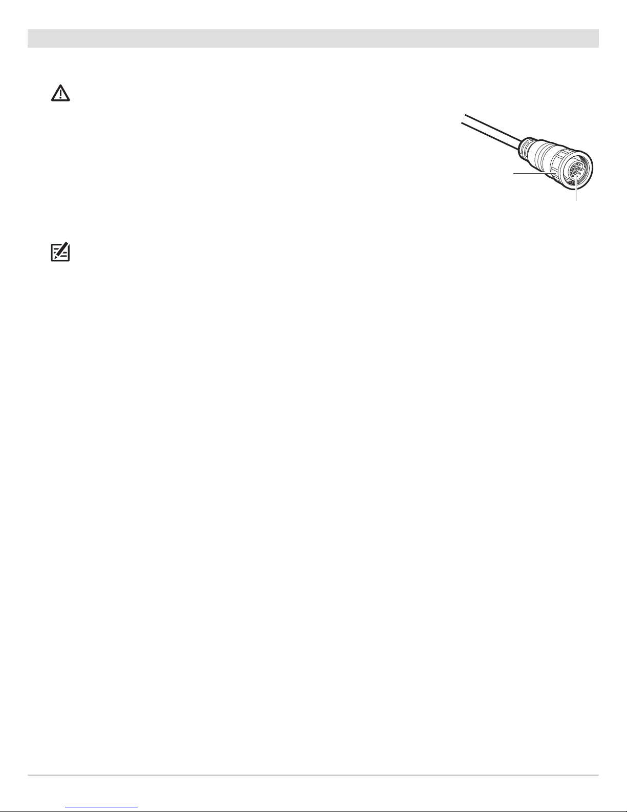
2. Locate the Ethernet cable on the i-Pilot Link.
3. If you are using the Ethernet extension cable for your installation, connect it to the
Ethernet cable on the i-Pilot Link. Hand-tighten the screw nut.
If you do not need the Ethernet extension cable for your installation, proceed to step 4.
4. Route the cable to the Humminbird control head (SOLIX, ONIX, or ION) or optional Ethernet
Switch.
NOTE: The cable should be routed through an established routing system on the boat, in an area
with minimal interference. Inspect the selected route carefully to ensure that there are no sharp
edges, obstacles, or obstructions that may damage the cables.
5. Humminbird Control Head (SOLIX, ONIX, or ION): Connect the Ethernet Cable connector to
the Ethernet port on the Humminbird control head.
Ethernet Switch: Connect the Ethernet Cable connector to an available Ethernet port.
6. Hand-tighten the screw nut to secure the connection.
Connecting the Ethernet Cable
screw nut
The connectors are keyed to
prevent reversed installation.
9
Installation
Page 10
|
Confirm i-Pilot Link Connection on the Humminbird Control Head
4
After connecting the i-Pilot Link to the Humminbird control head, it is important to confirm the connection. All equipment should
be connected and powered before you turn on the SOLIX, ONIX, or ION.
NOTE: If i-Pilot Link is connected during navigation, a message will display on-screen and navigation will be canceled.
Power On
1. Turn on the power source and i-Pilot Link equipment.
2. Press the POWER key on the SOLIX, ONIX, or ION.
3. Select Start Normal Mode. When the first view is displayed on the screen, the control head is ready for operation.
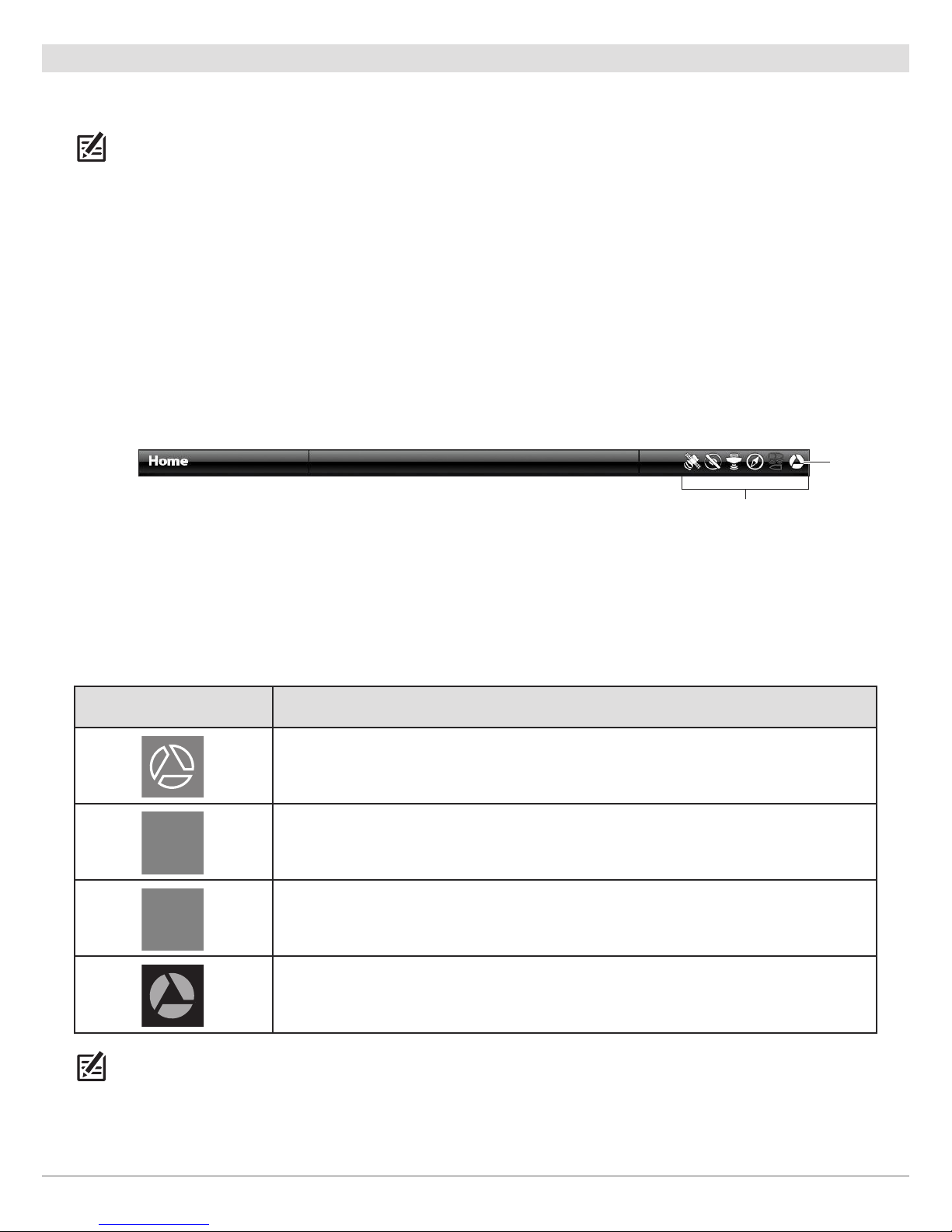
Check the System Status Bar
You can confirm i-Pilot Link connection by checking the system status bar. Each accessory connected to the Humminbird control
head is represented by a status icon in the system status bar.
Status Bar (top of the screen) (ONIX, ION)
i-Pilot Link
status icon
system status bar
1. Press the HOME key.
2. Review the top, right corner of the status bar.
Confirm the i-Pilot is shown as Connected and Detected. It may take up to one minute for the i-Pilot to be detected.
Unconnected: If the i-Pilot icon is not shown in the status bar, check the cable and power connections to confirm they are
secure and powered on. Review the installation guide that was included with your i-Pilot Link to confirm it is installed correctly.
i-Pilot Link Status Icon Icon Description
Connected and Detected: i-Pilot Link is connected and detected on the network.
Detected and Enabled: i-Pilot Link is connected to the network, enabled, and ready to be
used for navigation or currently being used in manual mode (prop on, but not navigating).
Detected, Enabled, and Actively Navigating: i-Pilot Link is connected to the network,
enabled, and actively navigating.
Connected, but not Detected or Active: i-Pilot Link is connected, but not detected on
the network or enabled.
NOTE: For additional system information, select Home > Settings > Network > System Info.
Installation
10
Page 11

|
Confirm GPS Reception
5
Use the instructions in this section to confirm the control head has GPS reception. GPS is required to enable the navigation features
on the control head with i-Pilot Link.
Check the System Status Bar
1. In the Home screen, review the top, right corner of the status bar, confirm the GPS receiver is detected and active.
GPS Status Icon Icon Description
Detected and Active: The GPS receiver is detected and a GPS fix has been obtained.
Connected but not Transmitting/Receiving: The GPS receiver is detected, but it doesn’t
have a GPS fix.
Connected but not Detected or Active: The GPS receiver is connected, but not detected
on the network or no GPS fix has been obtained.
2. If the Detected and Active icon is visible, GPS fix has been obtained.
If the GPS icon is not displaying in the system status bar, check the installation and the cable connection to the Humminbird
control head.
Check GPS Reception and Satellite Strength
The GPS tool provides two ways to view the satellites communicating with the GPS Receiver. Yellow indicates that the satellite is being
used to determine your current position. Purple or Teal indicates that the satellite is being monitored but not used. The following
data is also displayed:
• Position (latitude and longitude)
• GPS Fix Type: reported as No Fix, 2D Fix, 3D Fix, or Enhanced. An Enhanced fix has been augmented using information from
WAAS, EGNOS, or MSAS. A 3D or Enhanced Fix is required for navigation.
• HDOP (the Horizontal Dilution of Precision): a GPS system parameter which depends on the current satellite configuration.
HDOP is used to calculate the Estimated Position Error.
Review Satellites
1. From the Home screen, select the GPS tool. Tap the icon, or press the ENTER key, to open.
2. Depending on your network configuration, select GPS (1) > Satellites or GPS (2) > Satellites.
NOTE: You can manually change which GPS receiver is the selected source for GPS (1) or GPS (2). For more information about GPS
and selecting GPS sources, see your control head operations manual.
11
Installation
Page 12
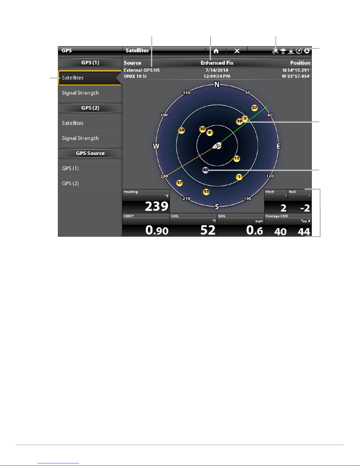
GPS (1) Satellite Sky Chart (ONIX)
satellites
communicating
to GPS (1)
selected GPS source
GPS status icon (detected and active)fix type
status bar
used
satellite
(yellow)
monitored
satellite
(purple)
digital
readouts
Installation
12
Page 13
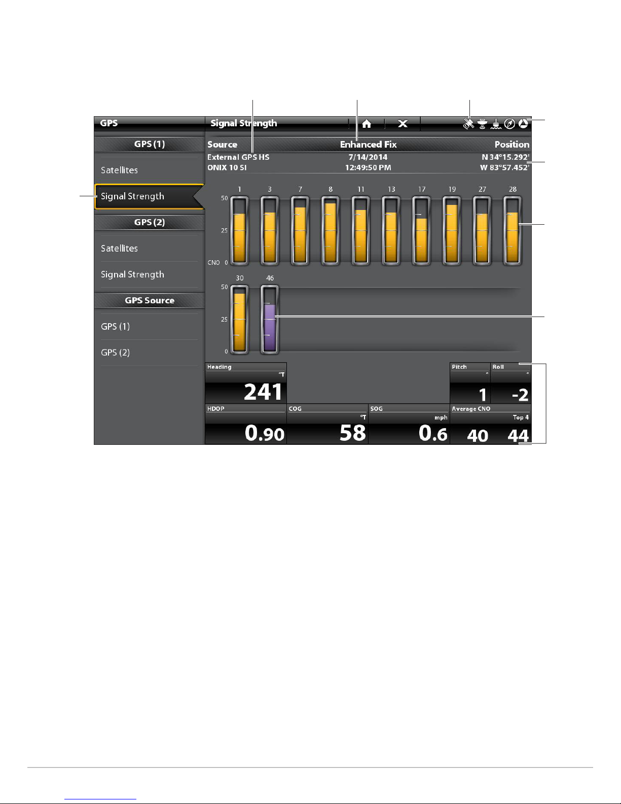
Review Satellite Signal Strength
1. Under GPS (1) or GPS (2), select Signal Strength.
Signal Strength (bar graph, ONIX)
satellites
signal strength
GPS (1)
selected GPS source
GPS status icon (detected and active)fix type
status bar
boat position
(latitude/
longitude)
used satellite
(yellow) and
strength level
monitored
satellite
(purple) and
strength level
Signal Strength (GPS 1/GPS 2): displays vertical bar graphs indicating the satellite
signal strengths with the respecting CNO (Carrier-to-Noise) value (0 to 60).
digital
readouts
13
Installation
Page 14
UPDATE SOFTWARE
Your control head model may need a software update to work with the i-Pilot Link. We recommend that you read the following
section complet
Control Head Software: Version 3.0 or later is required to use the i-Pilot Link with the SOLIX, ONIX, or ION control head. To check the
software version installed on your control head, select Home > Settings > Network > Network Info.
i-Pilot Link Remote and Controller: The i-Pilot Link has separate software updates for the controller and remote. After the software
is updated on the control head, you must go to the remote and initiate the download of the remote software to the remote itself.
See your i-Pilot Link Owner’s Manual for details.
Preparation: We recommend that you read the following section completely before starting any software updates. The Humminbird
control head will take approximately 10 minutes to update, and each Humminbird control head on the network must be updated
individually. Accessories take approximately 3 minutes to update.
Supplies: In addition to your Humminbird equipment, you will need a PC with Internet access and a blank SD card. If you have an
ION, you can use a USB stick.
|
Register your Humminbird Products
1
Set up an online account and register your Humminbird equipment so that you will receive the latest Humminbird news, including
accessory compatibility and software update information.
ely before starting any software updates.
1. Go to our Web site at humminbird. Select Support > Register your Product. If you
already have a humminbird account, select My Humminbird.
2. Follow the on-screen prompts to create a new account and register your
products.
|
Export Settings and Navigation Data
2
Before the Humminbird control head software is updated or restored to system defaults,
export your menu settings, radar settings, and navigation data, and copy your screen
snapshots to an SD card.
WARNING! Humminbird is not responsible for the loss of data files (waypoints, routes,
tracks, groups, snapshots, recordings, etc.) that may occur due to direct or indirect damage
to the unit’s hardware or software. It is important to back up your control head’s data files
periodically. Data files should also be saved to your PC before restoring the unit’s defaults
or updating the software.
WARNING! Do NOT leave the control head SD card slot cover open. The slot cover should
always be closed to prevent water damage to the unit.
NOTE: See your control head operations manual for more information about exporting settings
and navigation data.
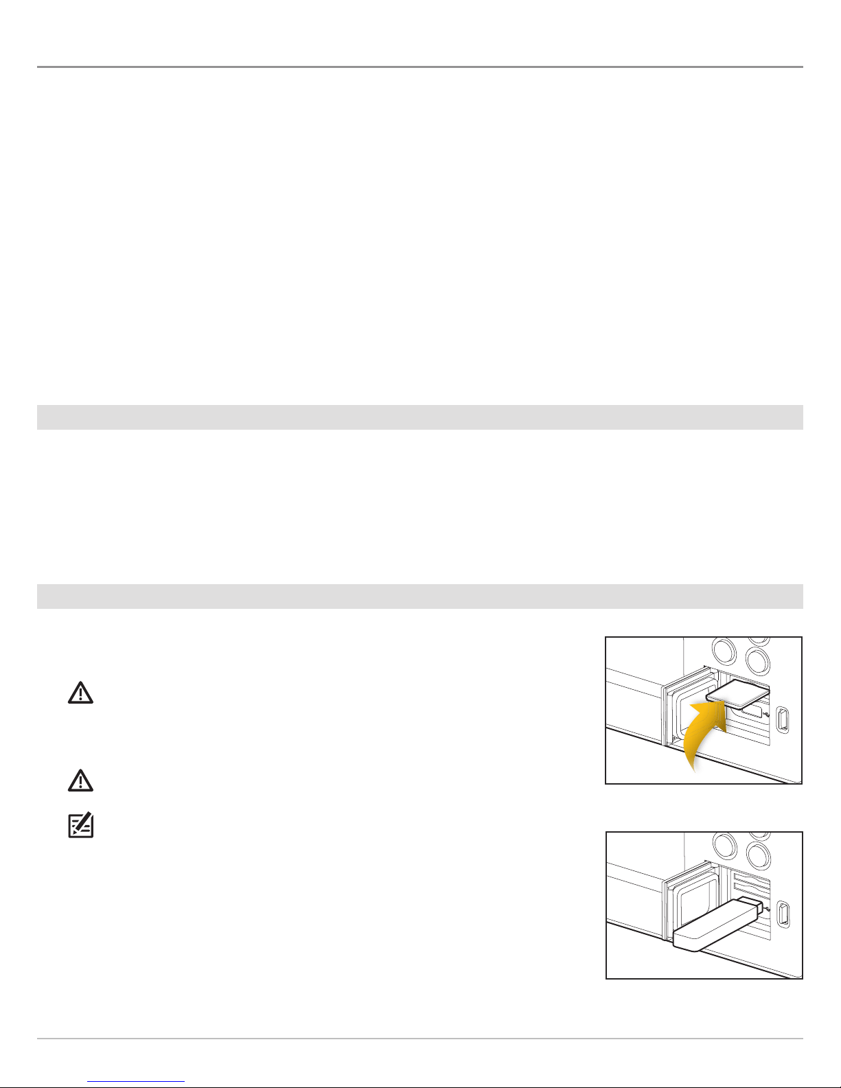
Insert a Blank SD Card
Inserting an SD Card (ONIX)
Inserting the USB Stick (ION)
1. Install the SD card according to the instructions in your control head operations
manual.
Insert a Blank USB Stick (ION only)
1. Insert the USB stick into the USB port.
Update Software
14
Page 15

Copy Internal Images
If you have screen snapshots saved to the control head, use the following instructions to copy them to an SD card.
1. Confirm the SD card is installed in the control head card slot.
2. Press the HOME key.
3. Select the Images tool. Tap the icon, or press the ENTER key, to open.
4. Under Source, select Internal.
5. Press and hold one of the screen snapshots.
OR
Use the Joystick to select a screen snapshot. Press the MENU key.
6. Select Copy All.
7. Select a Save Location: Save to the SD Card
SOLIX: left slot = SD Card 1, right slot = SD Card 2
ONIX, ION: top slot = SD Card 1, bottom slot = SD Card 2
8. Repeat the steps in this section on each control head.
|
Download Software Updates for the Humminbird Control Head
3
Perform the procedures in the following sections to update the SOLIX, ONIX, or ION control head software.
NOTE: Ethernet Switches and Sonar Black Boxes (SM1000/2000/3000) must be updated individually on the software update list.
See your control head operations manual for more information about updating accessory software.
Check the Current Software Version
It is helpful to review the software version number that is currently installed on the control head and each accessory.
1. Press the HOME key.
2. Select Settings.
3. Select Network > Network Info.
4. The Network Info dialog box shows a section for each device connected to the network. Scroll to each section to note the
software version number listed.
Download Software Updates
1. Install the SD card into the PC card slot.
2. Go to humminbird, and select My Humminbird to sign in to your account.
3. Select the My Equipment tab. The available software updates are listed as Downloads under each registered product.
• Under Downloads, click the file name.
• Read the instructions in the dialog box and select Download.
• Follow the on-screen prompts to save the software file to the SD card.
4. Repeat: Repeat step 3 to download the software updates posted to each registered product.
15
Update Software
Page 16
|
Update Software for the Humminbird Control Head
4
When you install the SD card with the software file, the control head will detect the update and provide an automatic prompt to install
the software. You can follow the prompts or choose to install the software at a later time through the Files tool. It is important to
review the following tips:
• Automatic Restart: The control head will restart during the software update process.
• Multiple Control Heads: If you have more than one control head on the network, go to each control head to install the latest
software update. Control head software updates cannot be updated through another networked unit.
WARNING! Before the control head software is updated or restored to system defaults, export your menu settings, radar settings, and
navigation data. Copy your screen snapshots to an SD card. See Export Settings and Navigation Data for details.
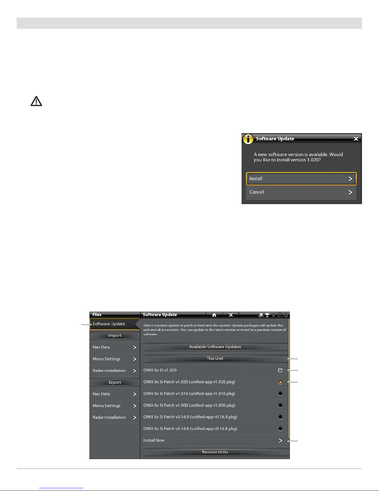
Update Software Automatically
1. Press the POWER key. Follow the on-screen prompts to start normal mode
on the control head.
2. Install the SD card with the software file(s) into the control head card slot.
3. A dialog box will display to start the software update.
To start the control head software update, select Install. When SUCCESS is
displayed, the software update is finished. If you have accessories to update,
proceed to Update Software for Connected Accessories.
OR
To update the software at a later time from the Files tool, select Cancel.
Update Software from the Files Tool
1. Install the SD card with the software file(s) into the control head card slot.
2. Press the HOME key.
3. Select the Files tool. Tap the icon, or press the ENTER key, to open.
4. From the Software Update tab, scroll to This Unit.
5. Confirm that the most current version of software is selected from the list. Select Install Now.
Software
Update tab
this unit
network dialog box
confirm the latest
version of software
is selected
Update Software
select Install Now
to start the
software update
16
Page 17

6. When SUCCESS is displayed, the software update is finished.
|
Update Software for Connected Accessories
5
Accessory software is updated from the Files tool, and the process is similar to updating the Humminbird control head software.
If you need to update additional accessories, see your control head operations manual for details.
NOTE: Ethernet Switches and Sonar Black Boxes (SM1000/2000/3000) must be updated individually on the software update list.
|
Update Software for the i-Pilot Link
6
The i-Pilot Link has separate software updates for the controller and remote. After the software is updated on the i-Pilot Link
controller, you must go to the remote and initiate the download of the remote software to the remote itself.
NOTE: See the i-Pilot Link Owner’s Manual for additional information about updating i-Pilot software.
Prepare the i-Pilot Link System
1. Turn on the main power source.
2. Power on the trolling motor.
As determined by your trolling motor model, deploy the motor or press the Power button.
3. Turn on the i-Pilot remote by pressing the OK key. Ensure the battery is well charged. If the battery charge is not sufficient,
you will be prompted during the process to plug in the charger.
4. Power on the SOLIX, ONIX, or ION. Follow the on-screen prompts to start Normal mode.
5. Confirm i-Pilot is connected. See Installation: Confirm i-Pilot Link Installation and Connection on the Humminbird Control
Head.
It may take a minute for the equipment to be detected.
If the i-Pilot Link is not detected on the network, confirm the cable connections are secure.
6. From the Home screen, select the Files tool. Tap the icon, or press the ENTER key, to open.
7. Note the current software version number shown next to i-Pilot Link.
Update the i-Pilot Link Controller Software
1. Install the SD card with the software file(s) into the Humminbird control head card slot.
2. Press the HOME key.
3. Open the Files tool.
4. From the Software Update tab, scroll to i-Pilot Link in the list.
5. Confirm that the most current version of software is selected from the list. Select Install Now.
The Link controller will restart during the software update process.
17
Update Software
Page 18

Software
Update tab
6. When the software update is finished, the new software version number will be displayed in the Files tool.
Update the i-Pilot Link Remote Software (i-Pilot Link only)
start the software
update
network dialog box
confirm the latest
version of software
is selected
confirm the latest
version of software
is selected
If you have an i-Pilot Link BT trolling motor, you can skip the instructions in this section (proceed to Restart the System).
1. Install the SD card with the software file(s) into the Humminbird control head card slot.
2. Press the HOME key.
3. Open the Files tool.
4. From the Software Update tab, scroll to i-Pilot Link Remote in the list.
5. Confirm that the most current version of software is selected from the list. Select Install Now.
The new software for the remote is now loaded on the Link Controller. You must go to the remote and initiate the download
of the remote software to the remote itself.
6. Go to the remote Home screen and select Settings Softkey > Update Software > OK.
7. Select Update.
8. A message saying “Software Updating” will be displayed with a progress bar. Then, a message saying “Programming Flash”
will be displayed with a progress bar.
9. When the software update is finished, the remote will automatically restart.
|
Restart the System
7
1. Entire System Restart: After all software has been updated, power off all control heads and connected equipment. Wait 10
seconds, and then power on all equipment.
2. Cycle power to the trolling motor to regain proper motor control.
Update Software
18
Page 19
CONFIGURE i-PILOT WITH THE CONTROL HEAD
Use the instructions in this section to set up i-Pilot on the Humminbird control head.
|
Enable i-Pilot Link Navigation
1
To start i-Pilot Link navigation from the SOLIX, ONIX, or ION, i-Pilot Navigation must be turned on. When i-Pilot Navigation is turned
on, the related i-Pilot Link menus will be added to the menu system.
If i-Pilot Navigation is turned off, your SOLIX, ONIX, or ION control head will operate with its traditional Humminbird navigation
features.
NOTE: If i-Pilot Link is connected during navigation, navigation will automatically be canceled. See Installation: Confirm i-Pilot
Link Installation and Connection on the Humminbird Control Head.
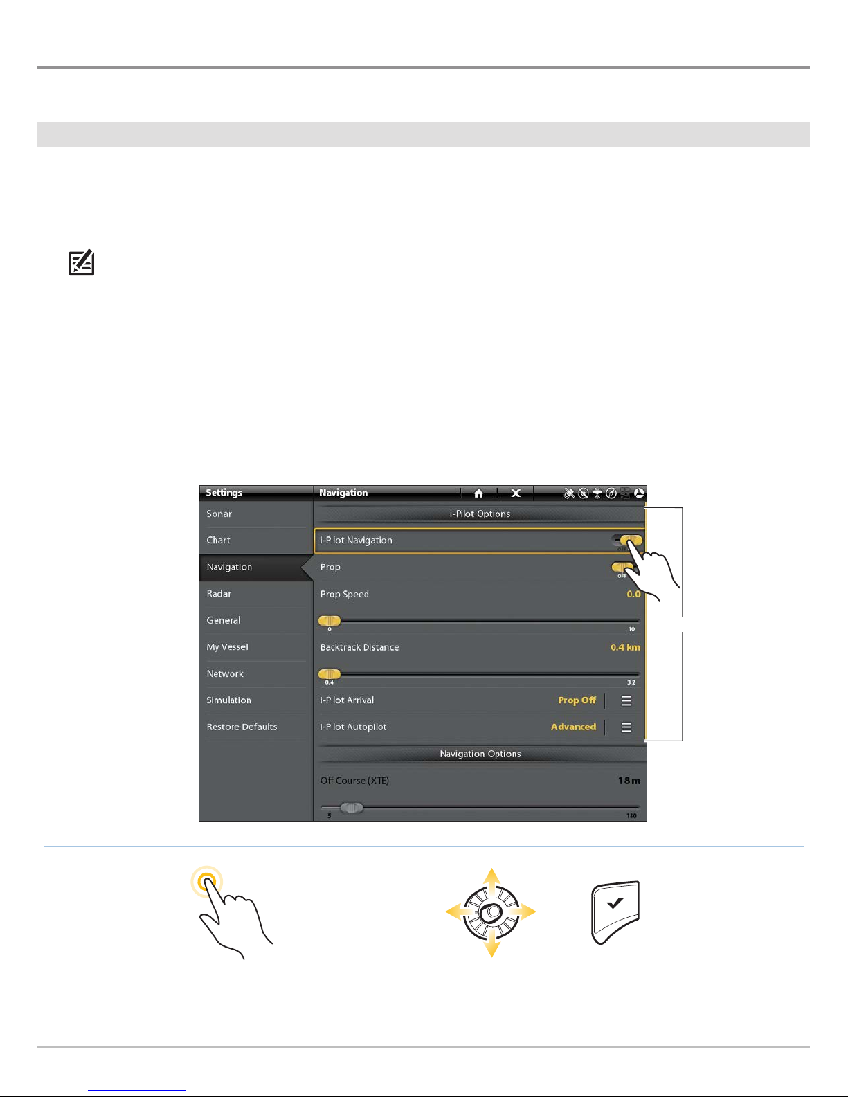
Enable i-Pilot Link Navigation
1. Press the HOME key. Select Settings.
2. Select Navigation.
3. Under i-Pilot Options, select i-Pilot Navigation.
4. Tap the on/off button, or press the ENTER key, to turn i-Pilot Navigation ON.
Turning On i-Pilot Link Navigation
i-Pilot options menu
Tap to Select Select Confirm
OR
19
Configuration
Page 20
|
Turn on/off Prop Auto-On (optional)
2
When Prop Auto-On is turned on, the i-Pilot Link will start the selected navigation mode as soon as it is selected. The propeller will
turn on at the current speed setting. If the Prop Auto-On menu is turned on, but the propeller is not turning, the speed might be
set to 0. See Propeller Controls for more information.
When Prop Auto-On is turned off, you must start the propeller manually each time you select an i-Pilot Link navigation mode.
However, this menu does not apply to Spot-Locks and Cruise Control. These navigation modes will turn on the propeller as soon as
they are engaged, regardless of the Prop Auto-On setting.
WARNING! Spot-Locks and Cruise Control will turn on the propeller as soon as they are engaged, regardless of the Prop Auto-On
setting.
Turn on/off Prop Auto-On
1. Under i-Pilot Options, select Prop Auto-On.
2. Tap the on/off button, or press the ENTER key, to turn it on or off.
WARNING! When Prop Auto-On is turned on, the propeller will turn on when navigation features are used. Navigation features
include working with iTracks and AutoPilot. Be sure the prop is clear from obstructions and hazards when using navigation
features.
|
Set the Arrival Mode
3
When you are navigating with the i-Pilot Link and reach the destination, set the Arrival Mode menu option to tell the system what
to do next. The setting will determine if you will control the boat manually or transition to another type of i-Pilot Link navigation after
the destination point is reached.
The Arrival Mode setting affects iTracks, routes, waypoints, and Spot-Locks. It does not apply to Follow the Contour or Circle Mode.
Set the Arrival Mode
1. Under i-Pilot Options, select i-Pilot Arrival.
Tap, or press the ENTER key, to open the i-Pilot Arrival submenu.
2. Select a menu option. Tap, or press the ENTER key, to select it.
i-Pilot Link Navigation Go To Menu Options
Turns off the propeller and returns the i-Pilot Link to manual mode after navigation is finished.
Prop Off
You must be prepared to take manual control of the boat.
WARNING! If AutoPilot is the current navigation mode, you must turn off the propeller separately.
See Propeller Controls.
Spot-Lock Creates and engages a Spot-Lock after navigation is finished. See Spot-Locks for details.
If the cursor is inactive, navigation begins in the direction of the boat’s Course Over Ground
(COG) setting. If COG is not available, the current Heading (Hdg) is used.
AutoPilot
If the cursor is active, navigation begins in the direction of the cursor’s position using bearing
data from the active cursor.
Configuration
20
Page 21
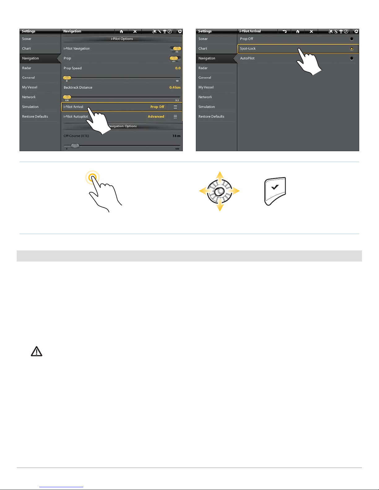
Opening the i-Pilot Arrival Submenu Setting the i-Pilot Arrival Mode
OR
Tap to Select Select Confirm
|
Install a Map Card
4
Use a Humminbird map card to provide detailed maps, depth contours, etc. on the chart views. To use Follow the Contour, an i-Pilot
Link-compatible Humminbird map card must be installed and selected as the map source.
i-Pilot Link Compatible Map Cards: Humminbird LakeMaster, LakeMaster PLUS, AutoChart ZeroLine, and ChartSelect.
1. Install an i-Pilot compatible map card.
See your control head operations guide for installation details.
2. The control head will select the map source automatically. To change the map source manually, select Settings > Chart.
WARNING! Do not leave the SD slot cover open. The slot cover should always be closed to prevent water damage to the unit.
21
Configuration
Page 22
|
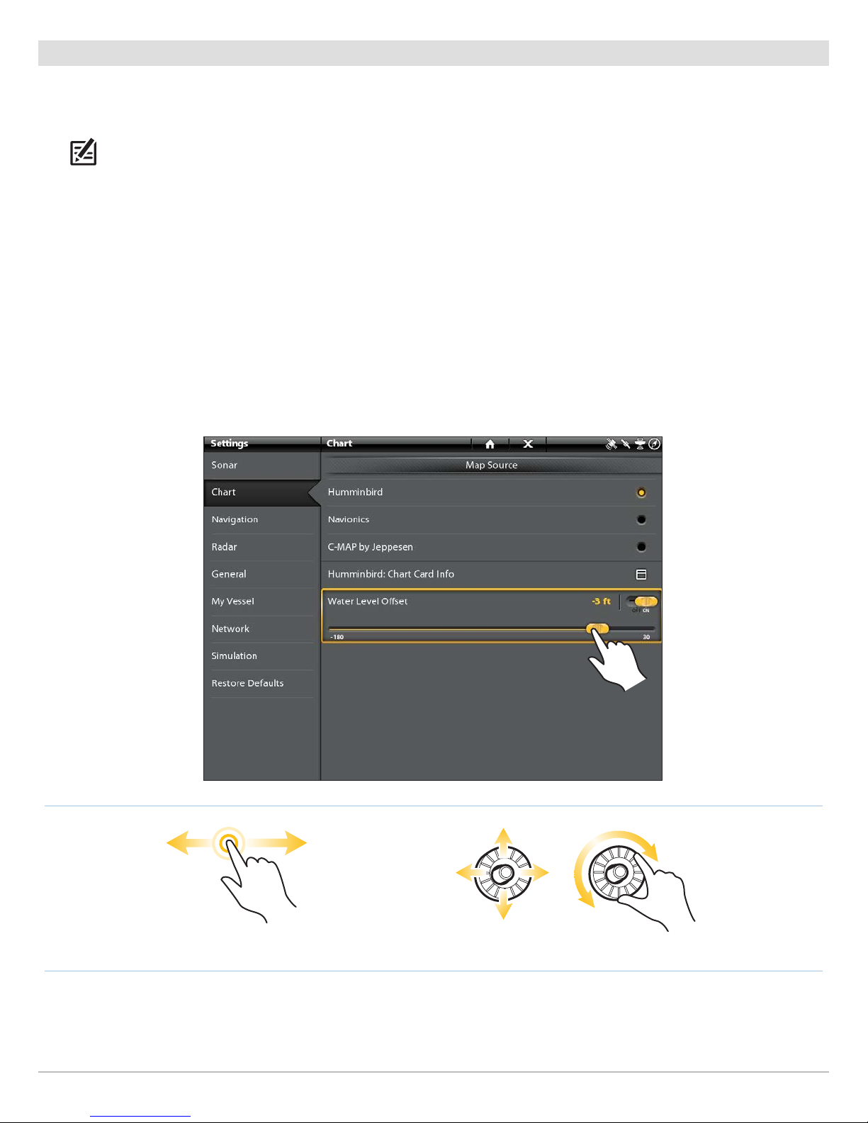
Set the Water Level Offset
5
Before starting navigation, set the Water Level Offset setting to change the water level read by the Humminbird control head. For
example, if the lake is down 5 feet, set the Water Level Offset setting to -5. The displayed numbers on the Contour Lines will adjust
from the Water Level Offset setting, and the water level offset will be highlighted in brown to extend the land visually on the display.
NOTE: Humminbird LakeMaster must be selected as the chart source to enable this feature.
To apply depth colors, depth highlight range, shallow water, etc., see Display Humminbird LakeMaster Contour Lines and Depth
Ranges.
Set the Water Level Offset
1. Under Settings, select Chart.
2. Under Map Source, select Water Level Offset.
3. On: Tap the on/off button, or press the ENTER key, to turn it on.
Adjust: Press and hold the slider, or turn the Rotary dial.
Setting the Water Level Offset
Press and hold OR Slide Select Turn to Adjust the Setting
Configuration
OR
22
Page 23
|
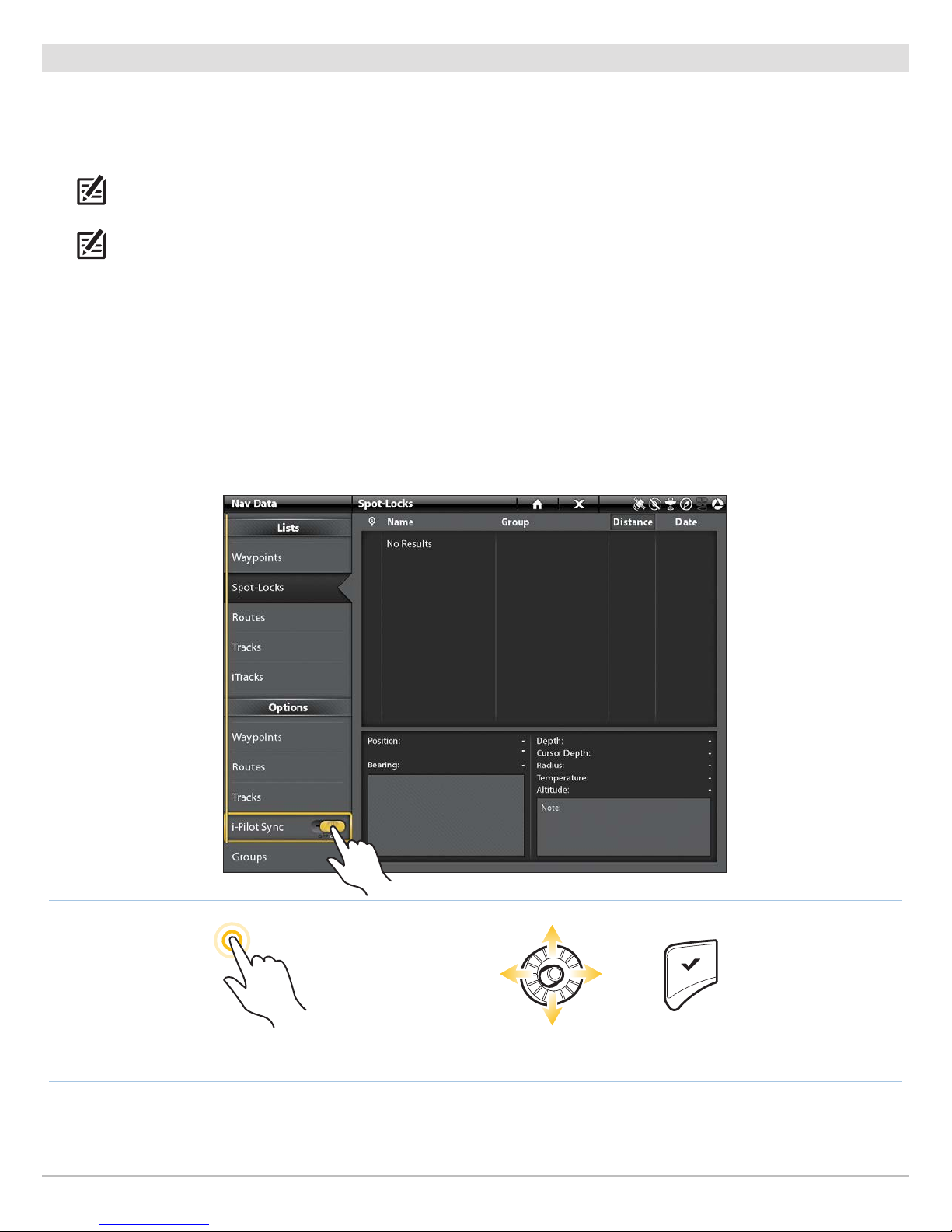
Turn On i-Pilot Sync
6
Turn on i-Pilot Sync to upload saved iTracks and Spot-Locks from the i-Pilot Link. When i-Pilot Sync is turned On, saved iTracks and
Spot-Locks from the i-Pilot Link are transferred to the SOLIX, ONIX, or ION, and saved iTracks and Spot-Locks from the SOLIX, ONIX,
or ION control head are transferred to the i-Pilot Link. Data will be transferred when you power on the SOLIX, ONIX, or ION, as well
as any time new data is created on the i-Pilot unit or the SOLIX, ONIX, or ION.
NOTE: If there is not enough available memory space on the control head, an error message will display and data will not be
transferred until more space is created on the Humminbird control head. See your control head operations manual for information
about managing navigation data.
NOTE: For more information about exporting navigation data, see Manage your i-Pilot Link Navigation Data.
Turn On i-Pilot Sync
1. Press the HOME key.
2. Select the Nav Data tool. Tap the icon, or press the ENTER key, to open.
3. Under Options, select i-Pilot Sync.
4. Tap the on/off button, or press the ENTER key, to turn it on.
Turning On i-Pilot Sync
Tap to Select Select Confirm
OR
23
Configuration
Page 24
SET UP i-PILOT LINK ALARMS
Use the instructions in this section to set i-Pilot Link alarms. When an alarm is turned on, an alert will sound and/or display on the
Humminbird control head to indicate the threshold has been met or exceeded. For more information about alarms or to set additional
alarms, see your control head operations manual.
NOTE: When i-Pilot Navigation is turned on in the menu system, the Arrival Alarm in the Alarms menu is replaced by the i-Pilot
Pre-Arrival Alarm, and the Off Course (XTE) Alarm is replaced by the i-Pilot Off Course (XTE) Alarm.
ION only: If you have connected the Alarm cable (separate purchase required) to an external klaxon or horn, select External Alarms.
Tap the menu name, or press the ENTER key, to add a check mark to the items that will trigger an external alert.
|
Set the Pre-Arrival Alarm
1
The i-Pilot Link Pre-Arrival Alarm provides an alert when the boat is within the set distance to the destination point in a waypoint,
route, or iTrack. For example, if i-Pilot Link is navigating an iTrack, and the Pre-Arrival Alarm is set to 100 feet, the alert will trigger
when the boat is within 100 feet from the iTrack End Point.
CAUTION! When the alert sounds, the i-Pilot Link will soon transition to the type of navigation set in the Arrival Mode menu option. Be
prepared that you may need to take manual control of the boat. See Configure i-Pilot with the Control Head: Set the Arrival Mode.
1. Press the HOME key.
2. Select Alarms.
3. Under Settings, select Network Alarms.
4. Select Navigation.
5. Under i-Pilot Alarms, select Pre-arrival.
6. On/Off: Tap the on/off button, or press the ENTER key, to turn it on
Adjust: Press and hold the slider, or turn the Rotary dial, to adjust the alarm threshold.
Alarms
24
Page 25
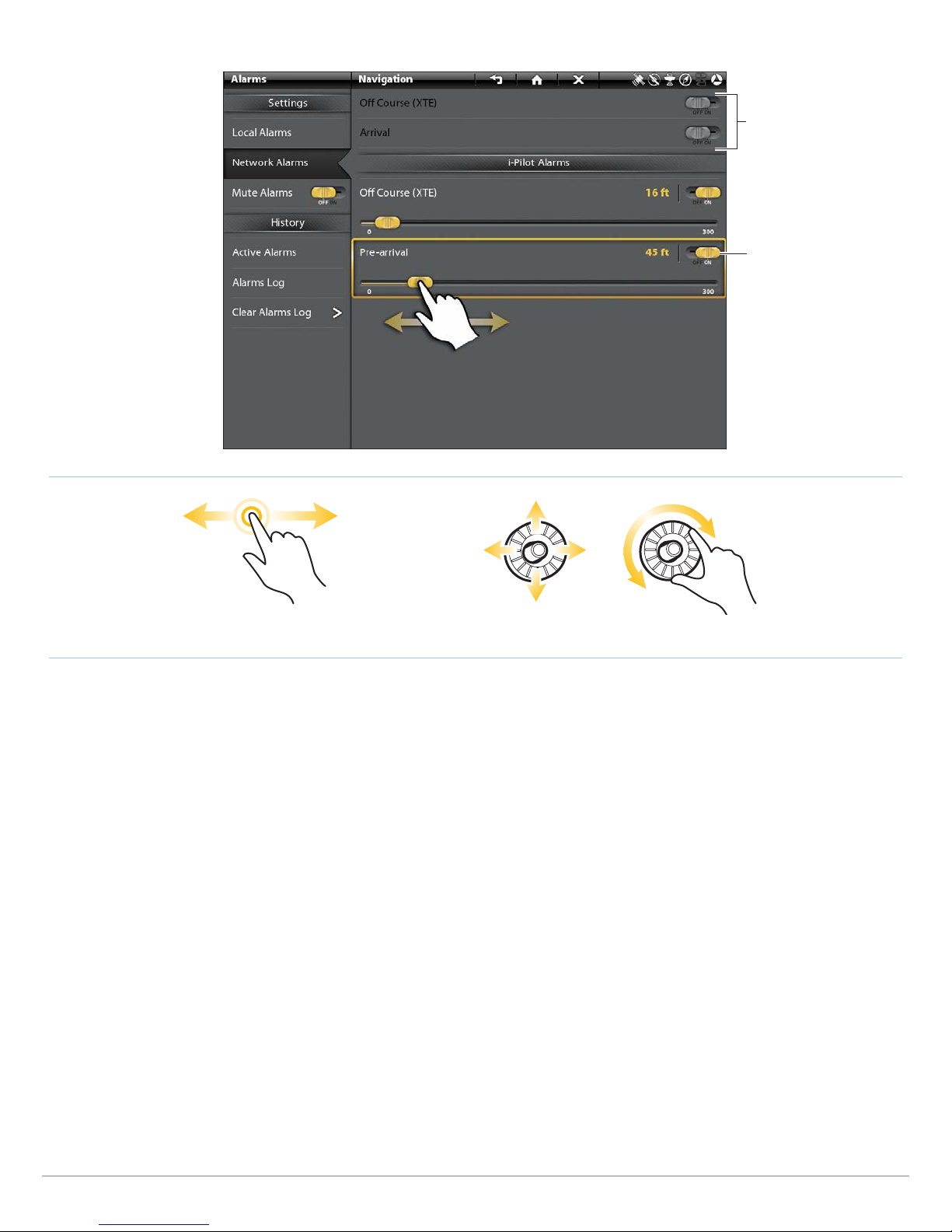
Setting the i-Pilot Link Pre-Arrival Alarm
When i-Pilot Navigation is
turned on, the Arrival Alarm
is replaced by the i-Pilot
Pre-Arrival Alarm, and the
Off Course (XTE) Alarm is
replaced by the i-Pilot Off
Course (XTE) Alarm.
Turn the alarm On, then
adjust the setting.
OR
Press and hold OR Slide Select Turn to Adjust the Setting
25
Alarms
Page 26
|
Set the Off Course (XTE) Alarm
2
The i-Pilot Link Off Course (XTE) Alarm provides an alert when the boat has traveled outside the selected route. You can set how
far the boat is allowed to move off course before the alarm is triggered.
NOTE: To set the Off Course (XTE) parameters and display the Off Course (XTE) Limit, see your control head operations manual.
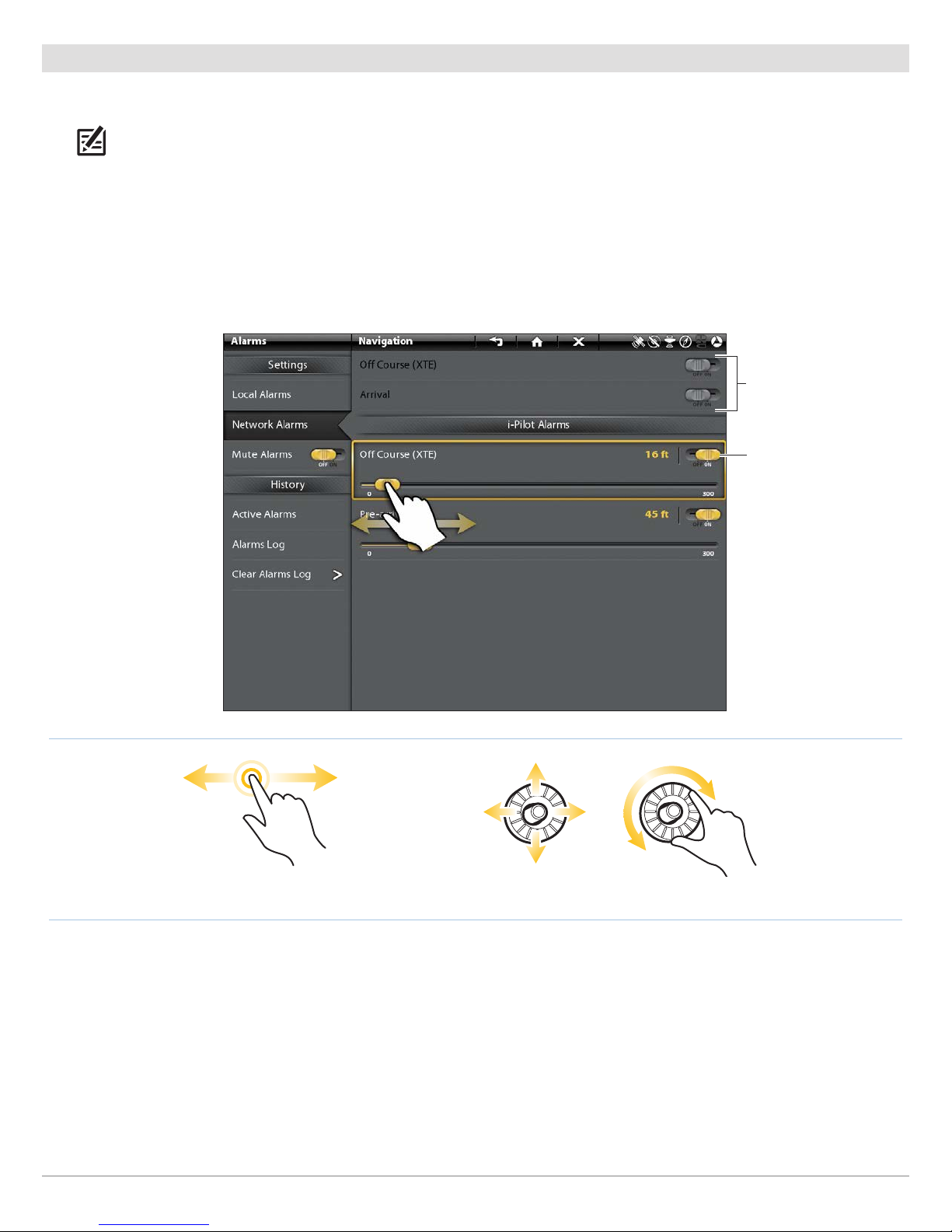
1. From the i-Pilot Alarms menu, select Off Course (XTE).
2. On/Off: Tap the on/off button, or press the ENTER key, to turn it on.
Adjust: Press and hold the slider, or turn the Rotary dial, to adjust the alarm threshold.
Setting the i-Pilot Link Off Course (XTE) Alarm
When i-Pilot Navigation is
turned on, the Arrival Alarm
is replaced by the i-Pilot PreArrival Alarm, and the Off
Course (XTE) Alarm is
replaced by the i-Pilot Off
Course (XTE) Alarm.
Turn the alarm On, then
adjust the setting.
Press and hold OR Slide Select Turn to Adjust the Setting
Alarms
OR
26
Page 27
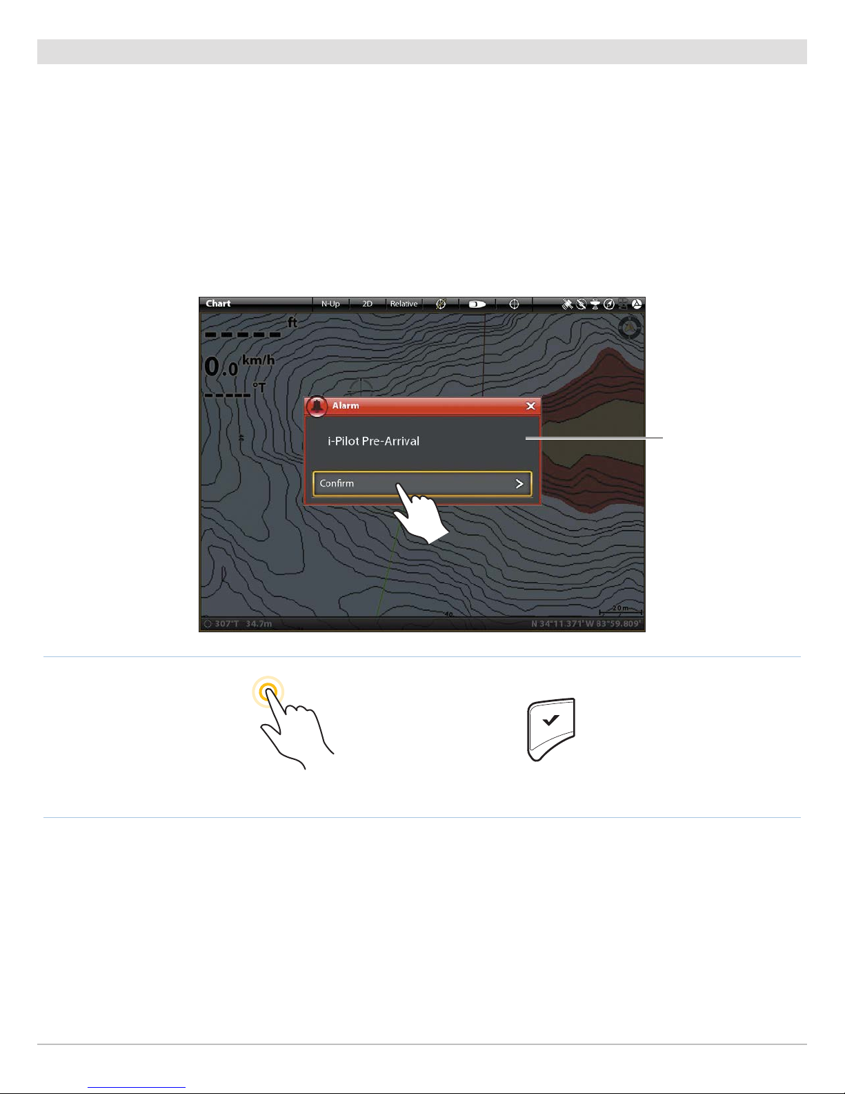
Confirm an Activated Alarm
When an alarm is triggered, an alert will sound and/or display on-screen to indicate the threshold has been exceeded. Use the
instructions below to silence a triggered alarm.
1. In the on-screen alarm notification box, tap Confirm.
OR
Press the ENTER key.
Confirming an Activated i-Pilot Alarm
on-screen alarm
notification
Tap to Select
OR
27
Confirm
Alarms
Page 28
DISPLAY DIGITAL READOUT BOXES
The i-Pilot Link data bar includes preset data boxes displaying i-Pilot Link navigation information, such as the current method of
navigation (iTrack, route, AutoPilot, etc.) and Prop Speed. For more information about customizing your Chart display, see your
control head operations manual.
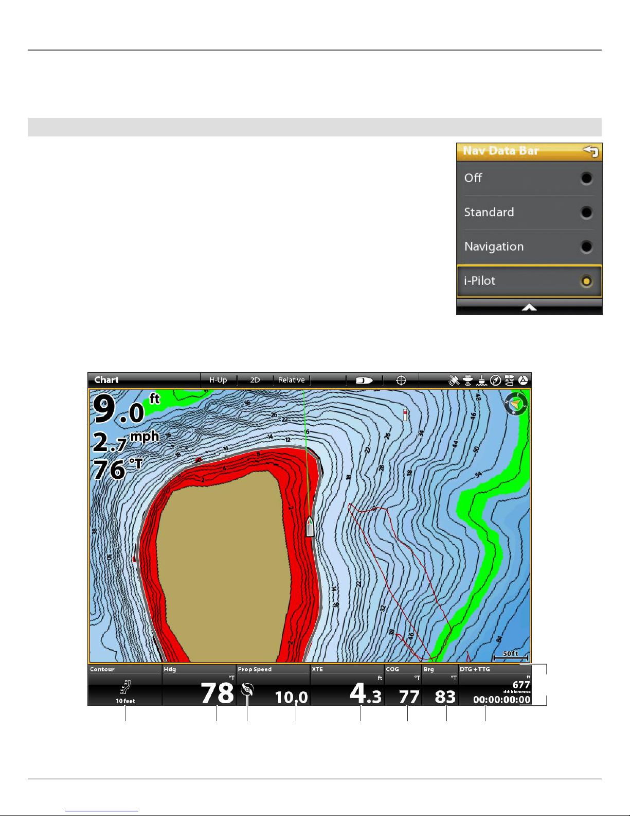
Display the i-Pilot Data Bar
1. Press the Home key. Select the Chart View.
2. Press the PANE key once.
In a multi-pane view, press the PANE key repeatedly until the status bar turns yellow.
3. To display the i-Pilot Link Data Bar during navigation, select Nav Data Bar from the View
Options menu.
To display the i-Pilot Link Data Bar during standard operation (not navigating), select
Data Bar from the View Options menu.
4. Select i-Pilot.
5. Press the EXIT key until the menu is closed.
Chart View with i-Pilot Link Navigation Data Bar Displayed (ONIX)
Navigation data box
will change to display
the current method
of navigation.
heading (Hdg) bearing
Digital Readout Boxes
propeller status icon
and propeller speed
cross track error
(XTE)
28
course over
ground (COG)
(Brg)
i-Pilot
data bar
distance to go (DTG)
+ time to go (TTG)
Page 29
i-Pilot Link Data Boxes
The i-Pilot Link Data Bar displays the following information in the preset data boxes:
Data Box Data Box Description
The current method of navigation. For example, whether you are currently navigating
Navigation
Heading (Hdg)
to a waypoint, route point, Spot-Lock, etc. Or, if you are currently navigating an iTrack,
route, contour, or navigating with AutoPilot (Advanced or Legacy).
The direction the boat is pointing, measured in degrees. Due to wind and waves, the
boat is often traveling in a slightly different direction than its heading. See Course Over
Ground (COG).
Propeller Status and Speed
Cross Track Error (XTE)
The current i-Pilot Link propeller status (on, on and rotating, off) and the propeller
speed.
The straight-line distance of the boat from the intended Track. XTE measures how far
the boat is off course.
The current direction the boat is traveling, measured in degrees from North. When the
Course Over Ground (COG)
COG is equal to Bearing, the boat is said to be on course and will arrive at the
destination in the most efficient manner.
Bearing (Brg) The compass direction from the vessel position to the next waypoint or route point.
Distance to Go (DTG) +
Time to Go (TTG)
The distance between the vessel position and the next point on the current route, and
the estimated time required to reach the next point on the current route.
Change the Data Boxes (optional)
To change the data boxes displayed in the data bar, see your control head operations manual.
29
Digital Readout Boxes
Page 30
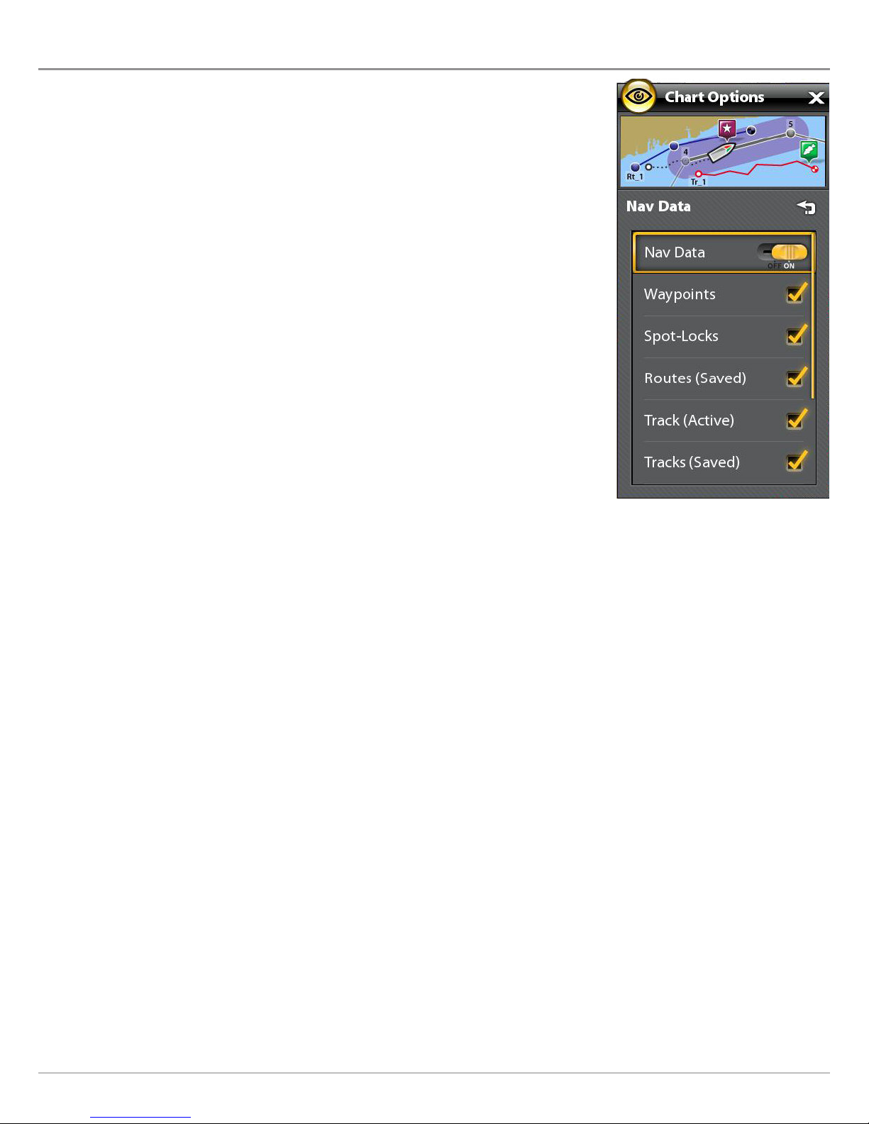
DISPLAY SPOT-LOCKS AND iTRACKS ON THE CHART VIEW
Use the following instructions to display Spot-Locks and iTracks on the Chart View. For more
information about customizing your Chart display, see your control head operations manual.
1. With Chart View displayed on-screen, tap Chart in the status bar.
OR
Press the MENU key once.
2. Select Chart Options.
3. Select Overlays > Nav Data.
4. On/Off: Tap the on/off button, or press the ENTER key, to select On.
5. Add a check mark to Spot-Locks to make them visible on the Chart View.
6. Add a check mark to iTracks to make them visible on the Chart View.
7. Press the EXIT key to close the menu.
Display Settings
30
Page 31

DISPLAY HUMMINBIRD LAKEMASTER CONTOUR LINES AND DEPTH RANGES
When you install a LakeMaster Map Card or LakeMaster PLUS Map Card, menu options are added to the menu system. You can
display or hide contour lines, highlight shallow water, and highlight a depth range on the map.
NOTE: A Humminbird LakeMaster Map Card must be installed and selected as the map source to enable these features. For details
and additional features related to your LakeMaster Map Card, see your control head operations manual.
1. With a Chart View displayed on-screen, tap Chart in the status bar, or press the MENU key once.
2. Select Chart Options.
3. Select Humminbird Settings.
4. Select the following menus to your preference.
Depth Colors Turn on Depth Colors and adjust the range for depth shading in the Chart Views.
Depth Highlight
Highlight Range
Shallow Water
Contour Interval
Turn on Depth Highlight to highlight a depth setting in the Chart Views. The depth you set will be
highlighted in green. Use Depth Highlight with Highlight Range.
When a Depth Highlight is active in the Chart Views, use Highlight Range to highlight a range on each
side of the highlighted depth. For example, if you know a certain fish is holding at 18 to 20 feet, you
can set the Depth Highlight at 19 feet, and the Highlight Range a +/– 1 foot. The view will show a green
band from 18 to 20 feet.
Turn on Shallow Water and adjust the slider. When the depth is equal to or less than the amount set,
it will be highlighted in red in the Chart Views. For example, if your boat has a draft of 3 feet, set the
Shallow Water menu to 3 feet, and the unit will draw a red band from 0 to 3 feet.
Turn on Contour Interval to display lines at set intervals on the Chart View. Adjust the slider to set the
distance between each line. Contour Interval is also affected by the Water Level Offset setting. See
Configure i-Pilot with the Control Head and Follow the Contour.
31
Display Settings
Page 32

chart
options
menu
Adjusting the Humminbird LakeMaster Display Settings (SOLIX)
depth colors
depth highlight
& depth
highlight range
(green)
contour line
(black line)
shallow water
highlight (red)
Display Settings
32
Page 33

DEPLOY OR STOW THE ULTERRA TROLLING MOTOR
If you have an Ulterra trolling motor installed, you can deploy or stow the motor using the X-Press Remote on the control head. Also,
see your i-Pilot Link Owner's Manual for details.
WARNING! Before you deploy or stow the motor, confirm the motor is clear from obstructions and has a clear path of travel. The
propeller is disabled while the motor is being trimmed to prevent accidental contact with the rotating propeller.
Open the Ulterra Dialog Box
Touch Screen
1. Tap the top, right corner of the status bar.
2. Tap the remote.
3. Tap the Ulterra button
propeller off
Keypad
1. Press the POWER key.
2. Use the Joystick to select the remote.
3. Select the Ulterra button. Press the ENTER key.
Opening the Ulterra Deploy/Stow Dialog Box
OR
33
OpenSelect UlterraTap Ulterra to Open
Ulterra
Page 34

Deploy the Motor
The first time you deploy the motor (after installation or after defaults have been reset), you will adjust the trim for operation. The
control head will save the most-recent trim setting and apply it when the motor is deployed again.
WARNING! As soon as Deploy is selected, the motor will deploy automatically. Before you deploy or stow the motor, confirm the
motor is clear from obstructions and has a clear path of travel. The propeller is disabled while the motor is being trimmed to
prevent accidental contact with the rotating propeller.
Touch Screen
1. Open the Ulterra dialog box.
2. Tap the Deploy button.
Trim Adjust (Installation only): Tap the Trim up or
down arrows.
Pause: Tap the Pause button.
Keypad
1. Open the Ulterra dialog box.
2. Select the Deploy button. Press the ENTER key.
Trim Adjust (Installation only): Select a Trim up or
down arrow. Press the ENTER key to move the motor in
the selected direction.
Pause: Select the Pause button.
Pause Deploying or Stowing
Use the following instructions to pause the trolling motor while it is being deployed or stowed.
Touch Screen
1. Open the Ulterra dialog box.
2. Tap the Pause button.
To resume deploying, see Deploy the Motor.
To resume stowing, see Stow the Motor.
Keypad
1. Open the Ulterra dialog box.
2. Select the Pause button. Press the ENTER key.
To resume deploying, see Deploy the Motor.
To resume stowing, see Stow the Motor.
Adjust the Trim
Use the following instructions to adjust the trim. The Trim menu is available when the motor is deployed. The control head will save
the most recent trim setting and apply it when the motor is deployed again, even after power off.
Touch Screen
1. Open the Ulterra dialog box.
2. Tap the Trim up or down arrows.
Keypad
1. Open the Ulterra dialog box.
2. Select a Trim up or down arrow. Press the ENTER key to
move the motor in the selected direction.
Prop on/off
Use the following instructions to turn on the prop from the Ulterra dialog box.
Touch Screen
1. Open the Ulterra dialog box.
2. Tap the Propeller button to turn it on/off.
Keypad
1. Open the Ulterra dialog box.
2. Select a Trim up or down arrow. Press the ENTER key to
move the motor in the selected direction.
Ulterra
34
Page 35

Adjusting the Trim (Ulterra only)
Turning on the Propeller (Ulterra only)
unavailable at
prop
this trim level
(red zone)
trim level
trim level
OR
NOTE: If a button is grayed-out, the action/command is unavailable.
Stow the Motor
Use the following instructions to stow the Ulterra trolling motor.
WARNING! As soon as Stow is selected, the motor will stow automatically. Before you deploy or stow the motor, confirm the
motor is clear from obstructions and has a clear path of travel. The propeller is disabled while the motor is being trimmed to
prevent accidental contact with the rotating propeller.
Touch Screen
1. Open the Ulterra dialog box.
2. Tap the Stow button.
ActivateSelectTap to Activate
Keypad
1. Open the Ulterra dialog box.
2. Select the Stow button. Press the ENTER key.
35
Ulterra
Page 36

i-PILOT LINK NAVIGATION OVERVIEW
i-Pilot Link uses GPS satellite signals as well as digital compass data to know where it is, where it is heading, and the direction the
motor is pointing. Since i-Pilot Link depends on GPS satellite signals for navigation, a minimum GPS signal level of one bar is required
in order for GPS navigation controls to be enabled. Best results are achieved when a GPS signal level of four bars can be obtained.
In simple terms, i-Pilot Link remembers and creates points to navigate your boat automatically. i-Pilot Link also uses a method of
GPS navigation called arrival circles. These imaginary circles allow i-Pilot Link to understand when it has drifted away from a point
and when it has arrived at a point. The size of the arrival circles vary depending on the GPS signal strength, thus the greater the signal
strength, the smaller the arrival circles.
Using i-Pilot Link with the Humminbird Control Head
• With a connected i-Pilot Link, you can initiate navigation from the Humminbird control head or Link remote, and the i-Pilot Link
will automatically start navigating the boat. Commands initiated from the remote will also be displayed on the SOLIX, ONIX, or
ION.
• The i-Pilot Link features and menu options are displayed in the Chart View and Radar View, as well as the Chart and Radar multi-
pane views. The following sections in this manual include instructions for the Chart View. The instructions will work the same
for the Radar View, except for Follow the Contour navigation, which is not available in the Radar View.
• Depending on your model and network configuration, the Humminbird control head uses GPS data from the internal or external
(networked) GPS receiver.
• Some of the i-Pilot Link navigation functions may override traditional Humminbird navigation menu options. Alarms have also
been adapted to the i-Pilot Link.
• To use Follow the Contour, a Humminbird LakeMaster Map Card, AutoChart ZeroLine Map Card, or AutoChart Live connection
is required.
Navigation Overview
36
Page 37

Open the Chart View
You can open the Chart View from the Favorites bar or the Views tool.
1. Press the HOME key. Locate the Favorites bar.
2. Tap the Chart View to display it on-screen.
OR
Use the Joystick to select the Chart View and press the ENTER key to display it on-screen.
Selecting the Chart View (SOLIX)
OR
37
OpenSelectTap to Open
Navigation Overview
Page 38

i-Pilot X-Press Remote Overview
Open the i-Pilot X-Press Remote
i-Pilot Navigation modes can be started from the X-Press Remote or the Go To menu. The X-Press Remote can be accessed from
any view. This section is an overview. Each navigation mode is detailed throughout this manual. See Propeller Controls for more
information.
Touch Screen
1. Tap the top, right corner of the status bar.
2. Tap the remote.
Opening the Power X-Press Menu (SOLIX) Opening the X-Press Remote (SOLIX)
Keypad
1. Press the POWER key.
2. Select the remote.
Navigation Overview
OR
SelectOpenTap to Open
38
Page 39

i-Pilot X-Press Remote
propeller on/off
start autopilot
record an iTrack
propeller speed
i-Pilot propeller controls
start cruise control
start high speed bypass
(10 mph)
spot-Lock at
boat position
start circle mode
NOTE: If a button is grayed-out, the action/command is unavailable.
open Go To menu
start BackTrack
39
Navigation Overview
Page 40

Go To Menu Overview
The Go To menu starts navigation to the item you select. You can also cancel navigation from this menu. The Go To menu can be
opened from the status bar, the GO TO key, or the X-Press Remote.
Open the Go To Menu from the Status Bar
Touch Screen
1. Tap Chart in the status bar.
2. Select Go To.
Keypad
1. Press the GO TO key.
Opening the Go To Menu (SOLIX)
Tap to Open
Navigation Overview
OR
Open
40
Page 41

Open the Go To Menu from the X-Press Remote
Touch Screen
1. Open the X-Press Remote: Tap the top, right corner of
the status bar. Tap the remote.
2. Tap the Go To button.
Opening the Go To Menu from the X-Press Remote
Keypad
1. Open the X-Press Remote: Press the POWER key.
Select the remote.
2. Select the Go To button. Press the CHECK/ENTER key.
Tap to Open the
Go To Menu
OR
41
OpenSelect the Go To Button
Navigation Overview
Page 42

Mark Menu Overview
Use the Mark menu to save a waypoint, save a Spot-Lock, or record an iTrack. This section is an overview. Each navigation mode is
detailed throughout this manual.
Touch Screen
1. Tap Chart in the status bar.
2. Select Mark.
Keypad
1. Press the MARK key.
Opening the Mark Menu (SOLIX)
Tap to Open
Navigation Overview
OR
Open
42
Page 43

|
Start i-Pilot Link Navigation
1
When i-Pilot Navigation is selected as the navigation source, the i-Pilot Link becomes the steering source for navigating points,
routes, iTracks, and contour lines. See Configure i-Pilot with the Control Head: Enable i-Pilot Link Navigation.
The i-Pilot Navigation modes can be accessed from the X-Press Remote or the Go To Menu. Also, you can open these menus from
any view. i-Pilot icons are available in Chart View and Radar View.
NOTE: If the boat doesn’t move when you start navigation, confirm the i-Pilot Link propeller is turned on (see Propeller Controls).
1. Tap Chart in the status bar, or press the Go To key. Select Go To.
OR
Open the X-Press Remote.
2. Select a navigation mode. This section is an overview. Each navigation mode is detailed throughout this manual.
i-Pilot Link Navigation Options
Select Spot-Lock to create and start navigation to a temporary Spot-Lock position, either at
Spot-Lock
the boat’s position or the cursor position. If you select Spot-Lock while navigating a route,
BackTrack, iTrack, or contour, navigation will be paused on the Spot-Lock. See the Spot-Lock
section for more information.
Follow the Contour
(Chart View only)
Circle
AutoPilot
BackTrack
Select Follow the Contour to start navigating the selected contour line. See the Follow the
Contour section for compatible Map Card information and details. This feature is available in
the Chart View only.
Select Circle Mode to set a point to navigate around. You can select clockwise or
counterclockwise. See the Circle Mode section for details.
If the cursor is inactive, navigation begins in the direction of the boat’s Course Over Ground
(COG) setting. If COG is not available, the current Heading (Hdg) is used.
If the cursor is active, navigation begins in the direction of the cursor’s position using bearing
data from the active cursor.
See the AutoPilot section for details.
Select BackTrack to start navigating back through the Current Track, starting with the last
recorded track point. The Current Track will be converted to a saved iTrack. While navigating
BackTrack, the direction of navigation can be changed using the Reverse menu option. See
the BackTrack section for details.
Nav Data
Select Nav Data to start navigation to a saved waypoint, route, Spot-Lock, iTrack, etc. See
Manage Your i-Pilot Link Navigation Data for details.
43
Navigation Overview
Page 44

|
Cancel i-Pilot Link Navigation
2
When i-Pilot Link navigation is in progress, whether with an iTrack, Spot-Lock, route, etc., you can cancel navigation at any time using
the following instructions.
WARNING! When you cancel i-Pilot Link navigation, be prepared to take manual control of the boat.
Cancel Navigation (Go To Menu)
1. Tap Chart in the status bar to open the Navigation X-Press Menu. Tap Go To.
OR
Press the GO TO key.
2. Select Cancel Navigation.
3. Tap, or press the ENTER key, to cancel navigation.
NOTE: Confirm the prop is turned off.
Cancel Navigation (X-Press Remote)
1. Open the X-Press Remote.
2. Tap the active (yellow) button to turn it off. (Gray = Off)
NOTE: Confirm the prop is turned off.
Navigation Overview
44
Page 45

Find the Nearest i-Pilot Link Navigation Data
Use the Find Nearest menu to search for the closest Spot-Locks and iTracks, in addition to the closest waypoints, routes, and tracks.
From the search results, you can view more information or start navigation. Before proceeding, confirm the cursor is not active.
Find the Nearest Spot-Locks and iTracks
Touch Screen
1. Press and hold a position on the chart.
2. Select Find Nearest.
3. Select Spot-Locks or iTracks.
4. Select a Spot-Lock or iTrack name from the displayed
list.
5. View Information: Tap the Spot-Lock or iTrack name to
see more information if it is available.
Start Navigation: To start navigation to the selected
Spot-Lock or iTrack, press the GO TO key. Select Go To.
Then, turn on the i-Pilot Link prop.
Display in Chart View: To display the selected SpotLock or iTrack in Chart View, press the GO TO key. Select
Cursor To.
Keypad
1. Press the ENTER key.
2. Use the Joystick to select Find Nearest. Press the
ENTER key.
3. Select Spot-Locks or iTracks. Press the ENTER key.
4. Select a Spot-Lock or iTrack name from the displayed
list.
5. View Information: Select the Spot-Lock or iTrack name
and press the ENTER key to see more information if it
is available.
Start Navigation: To start navigation to the selected
Spot-Lock or iTrack, press the GO TO key. Select Go To
and press the ENTER key. Then, turn on the i-Pilot Link
prop.
Display in Chart View: To display the selected
Spot-Lock or iTrack in Chart View, press the GO TO key.
Select Cursor To.
Starting Navigation to the Selected iTrack (ONIX)Selecting iTracks from the Find Nearest Menu (ONIX)
Press and Hold to Open Cursor Menu
Tap to Open and Select
OR
Open Cursor Menu Select Open and Confirm
45
Navigation Overview
Page 46

PROPELLER CONTROLS (X-PRESS REMOTE)
A manual function is where the operator takes full control of the function, such as manually steering the motor or adjusting the
propeller speed.
The propeller can be controlled from the X-Press Remote. You can steer, increase or decrease speed, and start Cruise Control from
the X-Press Remote.
WARNING! If you use the X-Press Remote to steer, you are taking manual control, and the current navigation mode will be
canceled (with the exception of recording an iTrack).
WARNING! Watch for a turning propeller and be prepared for boat movement when working with each i-Pilot Link navigation
mode. The propeller will automatically turn on when i-Pilot Link navigation modes are engaged, even if the engagement is
accidental. A turning propeller can cause injury.
Propeller Icon
i-Pilot Link Propeller On - When the i-Pilot Link propeller is turned on, it is ready to be used for i-Pilot Link navigation.
Icons will display in the i-Pilot Link data bar indicating the current status of the i-Pilot Link prop (on, on and rotating,
off). See Display Digital Readout Boxes.
You will have to manually turn on the i-Pilot Link prop to start i-Pilot Link navigation; except when starting navigation
to a Spot-Lock from the Go To menu, in which case the propeller will automatically turn on to start navigation.
i-Pilot Link Propeller On and Rotating - The i-Pilot Link propeller is currently being used for i-Pilot Link navigation.
i-Pilot Link Propeller Off
off after the destination has been reached during i-Pilot Link navigation. See Configure i-Pilot with the Control Head:
Set the Arrival Mode.
You will have to manually turn off the i-Pilot Link prop when canceling AutoPilot navigation.
- If you selected Prop Off for the Arrival Mode, the i-Pilot Link propeller will automatically turn
Start or Stop the Propeller
The propeller must be started to start navigation with the i-Pilot Link. You can start the propeller manually each time you start
i-Pilot navigation, or you can set the propeller to turn on automatically when i-Pilot Link navigation is initiated (see Configure i-Pilot
with the Control Head: Turn on/off Prop Auto-On).
WARNING! Spot-Locks and Cruise Control will turn on the propeller as soon as they are engaged, regardless of the Prop Auto-On
setting.
Start or Stop the Propeller
Use the following instructions to start/stop the propeller manually using the X-Press Remote on the control head.
Touch Screen
1. Open the X-Press Remote: Tap the top, right corner of
the status bar. Tap the remote.
Keypad
1. Open the X-Press Remote: Press the POWER key.
Select the remote.
2. Tap the propeller button.
Yellow = On, Gray = Off.
Propeller Controls
2. Select the propeller button. Press the CHECK/ENTER
key.
Yellow = On, Gray = Off.
46
Page 47

Starting the Propeller
propeller on/off propeller speed
i-Pilot propeller controls
OR
Turn On/OffSelect the Prop ButtonTap to Turn On/Off
47
Propeller Controls
Page 48

Steer
Use the following instructions to steer manually using the X-Press Remote on the control head.
WARNING! When you use the X-Press Remote to steer, you are taking manual control of the i-Pilot Link, and the current navigation
mode will be canceled (with the exception of recording an iTrack).
Touch Screen
1. Open the X-Press Remote: Tap the top, right corner of
the status bar. Tap the remote.
2. Tap the left or right arrows.
Steering with the X-Press Remote
propeller on/off propeller speed
Keypad
1. Open the X-Press Remote: Press the POWER key.
Select the remote.
2. Turn the Rotary dial.
OR
Select a right or left arrow. Press the ENTER key.
i-Pilot propeller controls
Tap Arrows to Steer
Propeller Controls
OR
Turn to Steer
48
Page 49

Increase or Decrease Speed
Use the following instructions to adjust the i-Pilot link trolling motor speed manually using the X-Press Remote on the control head.
When the Steer/Prop menu is selected, you can use the +/- ZOOM keys to adjust the speed.
Touch Screen
1. Open the X-Press Remote: Tap the top, right corner of
the status bar. Tap the remote.
2. To increase the propeller speed, tap the + (PLUS)
button.
To decrease the propeller speed, tap the - (MINUS)
button.
Increasing or Decreasing Speed with the X-Press Remote
propeller on/off propeller speed
Keypad
1. Open the X-Press Remote: Press the POWER key.
Select the remote.
2. To increase the propeller speed, press the + (ZOOM IN)
key.
To decrease the propeller speed, tap the - (MINUS)
(ZOOM Out) key.
i-Pilot propeller controls
Tap the +/- Buttons to
Increase/Decrease Speed
OR
49
Decrease SpeedIncrease Speed
Propeller Controls
Page 50

Engage High Speed Bypass (HSB)
Use High Speed Bypass to automatically set the propeller speed to 10.
WARNING! Watch for a turning propeller and be prepared for boat movement when working with High Speed Bypass. High Speed
Bypass will automatically increase the propeller speed to 10 even if the engagement is accidental. A turning propeller can cause injury.
Engage High Speed Bypass
Touch Screen
1. Open the X-Press Remote: Tap the top, right corner of
the status bar. Tap the remote.
2. Tap the HSB button.
OR
Press and hold the + button.
Keypad
1. Open the X-Press Remote: Press the POWER key.
Select the remote.
2. Select the HSB button. Press the ENTER key.
OR
Press and hold the + (ZOOM IN) key.
Disengage High Speed Bypass
To exit High Speed Bypass, decrease the propeller speed or turn off the HSB button.
Touch Screen
1. Open the X-Press Remote: Tap the top, right corner of
the status bar. Tap the remote.
2. Tap the HSB button. (gray = off)
OR
Press and hold the + button.
Keypad
1. Open the X-Press Remote: Press the POWER key.
Select the remote.
2. Select the HSB button. Press the ENTER key. (gray = off)
OR
Press and hold the + (ZOOM IN) key.
OR
Tap the - button repeatedly to decrease speed.
OR
Press the − (ZOOM OUT) key repeatedly to decrease
speed.
Propeller Controls
50
Page 51

Engaging High Speed Bypass
propeller on High Speed Bypass active
i-Pilot propeller controls
OR
Turn On/OffSelect the HSB ButtonTap to Turn On/Off
51
Propeller Controls
Page 52

CRUISE CONTROL
Cruise Control helps to compensate for the variations in external forces that affect the speed over ground and keeps the boat
traveling at an even speed. When Cruise Control is engaged, the current speed over ground becomes the Target Speed. Cruise
Control works to control the propeller speed to match the Speed Over Ground to the Target Speed.
WARNING! Watch for a turning propeller and be prepared for boat movement when working with Cruise Control. The propeller will
automatically turn on when Cruise Control is engaged, even if the engagement is accidental. A turning propeller can cause injury.
The propeller will turn on for Cruise Control regardless of the Prop Auto-On setting.
Engage Cruise Control
Use Cruise Control to set the propeller to maintain a target speed.
Touch Screen
1. Open the X-Press Remote: Tap the top, right corner of
the status bar. Tap the remote.
2. Tap the Cruise button.
3. To increase the target propeller speed, tap the +
(PLUS) button.
To decrease the target propeller speed, tap the (MINUS) button.
Disengage Cruise Control
Touch Screen
1. Open the X-Press Remote: Tap the top, right corner of
the status bar. Tap the remote.
2. Tap the Cruise button.
3. To cancel navigation, tap the propeller button. (off =
gray).
Keypad
1. Open the X-Press Remote: Press the POWER key.
Select the remote.
2. Select the Cruise button.
3. To increase the propeller speed, press the + (ZOOM IN)
key.
To decrease the propeller speed, tap the - (MINUS)
(ZOOM OUT) key.
Keypad
1. Open the X-Press Remote: Press the POWER key.
Select the remote.
2. Select the Cruise button.
3. Press the ENTER key or press the Joystick.
4. To cancel navigation, select the propeller button. Press
the CHECK key to turn it off. (off = gray).
Cruise Control
52
Page 53

Adjusting the Cruise Control Speed
propeller on target propeller speed
i-Pilot propeller controls
Tap the +/— Buttons to
Increase/Decrease Speed
OR
Decrease SpeedIncrease Speed
53
Cruise Control
Page 54

SPOT-LOCKS
Spot-Lock uses a single point as a reference for the spot you want to stay on. Around the Spot-Lock location, i-Pilot Link
uses an arrival circle to determine prop speed and direction. If i-Pilot Link sees it is within the circle, it will adjust the motor
speed to zero. If i-Pilot Link sees it is outside of the circle, it will control motor speed in an attempt to get the boat back
into the circle.
Spot-Lock is based on the location of the motor, not the location or direction of the boat. Outside forces such as wind and current
will cause the boat to move. Spot-Lock will navigate to maintain the motor on the Spot-Lock location regardless of the position of
the boat.
WARNING! Watch for a turning propeller and be prepared for boat movement when working with Spot-Locks. The propeller will
automatically turn on when a Spot-Lock is engaged, even if the engagement is accidental. A turning propeller can cause injury.
The propeller will turn on for Spot-Locks regardless of the Prop Auto-On setting.
Storage: You can save a combination of up to 4,500 Spot-Locks and waypoints on your Humminbird control head, or up to 16 on
the Link Controller when operating without the Humminbird control head. Spot-Locks are saved with an alphanumeric name that
can be edited on the Humminbird control head through the Nav Data tool or from the Go To menu (while in the Chart View). You can
also change a saved waypoint to a Spot-Lock.
NOTE: Link differentiates between a Spot-Lock and a Waypoint only by its icon. Any waypoint can be converted to a Spot-Lock
by changing its icon to the Spot-Lock icon (see Manage your i-Pilot Link Navigation Data).
Spot-Locks
54
Page 55

Mark and Save a Spot-Lock
Use the following instructions to mark a Spot-Lock at the boat position. The Spot-Lock will be saved, but navigation will not start.
The Spot-Lock is saved to the Nav Data Tool. You can edit the name, etc. See Edit Saved Spot-Locks for more information.
Mark a Spot-Lock at the Boat Position
Before proceeding, confirm the cursor is not active. To start navigation, see Start Spot-Lock Navigation.
Touch Screen
1. Tap Chart in the status bar.
2. Select Mark.
3. Select Spot-Lock.
Select Spot-Lock to
mark a new Spot-Lock.
boat position
Keypad
1. Press the MARK key.
2. Use the Joystick to select Spot-Lock.
3. Press the ENTER key.
Marking a Spot-Lock at the Boat Position from the Mark Menu (ONIX)
saved Spot-Lock
Tap to Open Menus
Tap to Select
OR
Open Menu Select
55
Confirm
Spot-Locks
Page 56

Mark a Spot-Lock at the Cursor Position
You can use the cursor to mark a Spot-Lock location. To start navigation, see Start Spot-Lock Navigation.
Touch Screen
1. Tap a position on the chart to activate the cursor.
2. Tap Chart in the status bar.
3. Select Mark.
4. Select Spot-Lock.
Creating a Spot-Lock at the Cursor Position (ONIX)
Keypad
1. Use the Joystick to move the cursor to a position on
the chart.
2. Press the MARK key.
3. Use the Joystick to select Spot-Lock.
4. Press the ENTER key.
active cursor position
Tap to Activate the Cursor
Tap to Select
OR
Move the Joystick
to Activate the Cursor
Open Menu
Select Confirm
Spot-Locks
56
Page 57

Convert a Waypoint to a Spot-Lock in Chart View
You can convert a saved waypoint to a Spot-Lock using the instructions below. You can also convert a saved waypoint to a SpotLock in the Nav Data tool (see Manage your i-Pilot Link Navigation Data).
When the waypoint is converted to a Spot-Lock, the following menu options are disabled: icon editing, waypoint avoidance, and
depth marker.
Touch Screen
1. Tap the waypoint icon to select it.
2. Tap the Waypoint Name.
3. From the Waypoint Info menu, tap the Spot-Lock
on/off button to turn Spot-Lock ON.
If you start navigation to the Spot-Lock, Spot-Lock will
start automatically when the boat arrives.
Engaging Spot-Lock at a Waypoint Position (ONIX)
Turn Spot-Lock ON.
Keypad
1. Use the Joystick to move the cursor to the waypoint icon.
2. Press the ENTER key.
3. From the Waypoint Info menu, select Spot-Lock.
4. Press the ENTER key to turn Spot-Lock ON.
If you start navigation to the Spot-Lock, Spot-Lock will
start automatically when the boat arrives.
waypoint name
When Spot-Lock is turned
On, the waypoint icon
changes to a Spot-Lock icon.
Tap to Select Select Open
OR
57
Spot-Locks
Page 58

Start Spot-Lock Navigation
You can quickly Spot-Lock at the current boat position or the cursor position, and start navigation towards it automatically. This type
of Spot-Lock is temporary, and unless you save it, the Spot-Lock will be deleted when you start a new mode of navigation. To save
a Spot-Lock, see Mark and Save a Spot-Lock.
CAUTION! Be prepared for boat movement as the prop will automatically be enabled and the prop speed will automatically adjust
to move the boat to the Spot-Lock location. If the boat does not move, confirm the prop is turned on in the menu system (see
Propeller Controls).
Engage Spot-Lock at the Boat Position
You can Spot-Lock at the current boat position using the Go To menu or the X-Press Remote. Before proceeding, confirm the
cursor is not active.
Engage Spot-Lock at the Boat Position (Go To Menu)
Use the following instructions to engage a Spot-Lock at the boat position using the Go To menu.
Touch Screen
1. Tap Chart in the status bar.
2. Select Go To.
3. Select Spot-Lock.
Navigation will start automatically.
Cancel Navigation/Disengage Spot-Lock: Tap Chart in
the status bar. Select Go To > Cancel Navigation.
Canceling navigation will delete the Spot-Lock.
Keypad
1. Press the GO TO key.
2. Select Spot-Lock.
3. Press the ENTER key.
Navigation will start automatically.
Cancel Navigation/Disengage Spot-Lock: Press the
GO TO key. Select Cancel Navigation. Canceling
navigation will delete the Spot-Lock.
Spot-Locks
58
Page 59

Engaging Spot-Lock at the Boat Position (ONIX, Go To Menu)
boat position
OR
Tap to Open Go To Menu
Tap to Select
Engage Spot-Lock at the Boat Position (X-Press Remote)
Use the following instructions to engage a Spot-Lock at the boat position using the X-Press Remote.
Touch Screen
1. Open the X-Press Remote: Tap the top, right corner of
the status bar. Tap the remote.
2. Tap the Spot-Lock button to turn Spot-Lock ON.
Yellow = On, Gray = Off
Cancel Navigation/Disengage Spot-Lock: Tap the
Spot-Lock button.
Keypad
1. Open the X-Press Remote: Press the POWER key.
Select the remote.
2. Select the Spot-Lock button.
3. Press the ENTER key to turn Spot-Lock ON.
Yellow = On, Gray = Off
Cancel Navigation/Disengage Spot-Lock: Select the
Spot-Lock button. Press the ENTER key.
ConfirmSelectGo To
59
Spot-Locks
Page 60

Engaging a Spot-Lock at the Boat Position (X-Press Remote)
propeller turns on
automatically
propeller speed
Spot-Lock controls
(see Move a Spot-Lock)
OR
Turn On/OffSelect Spot-LockTap to Turn On/Off
Spot-Locks
60
Page 61

Spot-Lock
active
propeller on
Engaging Spot-Lock from the X-Press Remote (SOLIX)
Spot-Lock On X-Press
Remote
61
Spot-Locks
Page 62

Engage Spot-Lock at the Cursor Position
Engage Spot-Lock at the Cursor Position (Go To Menu)
Use the following instructions to start Spot-Lock navigation at the cursor position from the Go To menu. Engaging a Spot-Lock at
the cursor position is not available on the X-Press Remote.
CAUTION! Be prepared for boat movement as the prop will automatically be enabled and the prop speed will automatically adjust
to move the boat to the Spot-Lock location. If the boat does not move, confirm the prop is turned on in the menu system (see
Propeller Controls).
Touch Screen
1. Press and hold a position on the chart.
2. Select Go To.
3. Select Spot-Lock.
Navigation will start automatically.
Cancel Navigation/Disengage Spot-Lock: Tap Chart in
the status bar. Select Go To > Cancel Navigation.
Canceling navigation will delete the Spot-Lock.
Keypad
1. Use the Joystick to select a position on the chart.
2. Press the GO TO key.
3. Select Spot-Lock.
4. Press the ENTER key.
Navigation will start automatically.
Cancel Navigation/Disengage Spot-Lock: Press the
GO TO key. Select Cancel Navigation. Canceling
navigation will delete the Spot-Lock.
Using the Joystick to Select the Spot-Lock Position (ONIX) Navigating to the Spot-Lock (ONIX)
OR
Press and Hold
Tap to Select
Spot-Locks
Spot-Lock name start pointcursor end point
Select Go To Select Confirm
62
Page 63

Navigate to a Saved Spot-Lock
If a saved Spot-Lock is within 1/4 mile of the boat position, you can start navigation towards it. Spot-Lock will engage automatically
when the boat reaches the destination Spot-Lock.
CAUTION! Be prepared for boat movement as the prop will automatically be enabled and the prop speed will automatically adjust
to move the boat to the Spot-Lock location. If the boat does not move, confirm the prop is turned on in the menu system (see
Propeller Controls).
Select a Saved Spot-Lock in Chart View
Touch Screen
1. Tap a Spot-Lock icon on the chart.
2. Tap Chart in the status bar.
3. Select Go To.
4. Select Spot-Lock.
Navigation will start automatically.
Cancel Navigation/Disengage Spot-Lock: Tap Chart in
the status bar. Select Go To > Cancel Navigation.
Selecting a Saved Spot-Lock in Chart View (ONIX)
Spot-Lock name
boat icon
Keypad
1. Use the Joystick to select a Spot-Lock icon on the chart.
2. Press the GO TO key.
3. Select Spot-Lock.
4. Press the ENTER key.
Navigation will start automatically.
Cancel Navigation/Disengage Spot-Lock: Press the
GO TO key. Select Cancel Navigation.
Tap to Select Select Go To
OR
63
Spot-Locks
Page 64

Resume i-Pilot Link Navigation (Spot-Lock Pause)
If the i-Pilot Link is navigating a route, BackTrack, iTrack, or contour, and you engage a Spot-Lock, i-Pilot Link navigation will be
paused. Use the following instructions to resume navigation.
Resume i-Pilot Link Navigation (Go To Menu)
Touch Screen
1. During Spot-Lock Pause, tap Chart in the status bar.
2. Select Go To.
3. Select Resume.
Turn on the i-Pilot Link prop.
NOTE: See Propeller Controls for more details about turning the prop on or off and setting the prop speed.
Resuming Navigation from a Spot-Lock Pause (ONIX)
Keypad
1. During Spot-Lock Pause, press the GO TO key.
2. Select Resume. Press the ENTER key.
Turn on the i-Pilot Link prop.
boat engaged at Spot-Lock
i-Pilot Link data bar
indicating Spot-Lock Pause
Select Select Confirm
Spot-Locks
OR
64
Page 65

Resume i-Pilot Link Navigation (X-Press Remote)
When i-Pilot navigation is paused on a Spot-Lock, the button icon changes to indicate resuming navigation on the current route,
BackTrack, iTrack, or contour.
Touch Screen
1. During Spot-Lock Pause, open the X-Press Remote:
Tap the top, right corner of the status bar. Tap the
remote.
2. Tap the Spot-Lock button.
Resuming Navigation from a Spot-Lock Pause
propeller turns on
automatically
Keypad
1. During Spot-Lock Pause, open the X-Press Remote:
Press the POWER key. Select the remote.
2. Select the Spot-Lock button. Press the CHECK/ENTER
key.
propeller speed
OR
65
ResumeSelect Spot-LockTap to Resume
Spot-Locks
Page 66

Select a Saved Spot-Lock in the Nav Data Tool
Before proceeding, confirm the cursor is not active.
Touch Screen
1. Tap Chart in the status bar.
2. Select Go To.
3. Select Nav Data.
4. Under Lists, select Spot-Locks.
5. Press and hold a Spot-Lock. Select Go To.
6. Start Navigation: Select Go To to start navigation to
the selected Spot-Lock.
Display in Chart View: Select Cursor To to display the
selected Spot-Lock in Chart View.
Cancel Navigation/Disengage Spot-Lock: Tap Chart in
the status bar. Select Go To > Cancel Navigation.
Selecting a Saved Spot-Lock from the Nav Data Tool
Keypad
1. Press the GO TO key.
2. Select Nav Data. Press the ENTER key.
3. Under Lists, select Spot-Locks. Press the ENTER key to
display the list of Spot-Locks.
4. Use the Joystick to select a Spot-Lock.
5. Press the GO TO key.
6. Start Navigation: Select Go To and press the ENTER
key to start navigation to the selected Spot-Lock.
Display in Chart View: Select Cursor To to display the
selected Spot-Lock in Chart View. Press the ENTER key.
Cancel Navigation/Disengage Spot-Lock: Press the
GO TO key. Select Cancel Navigation.
Press and Hold to Open Go To Menu
Tap to Select
OR
Select Open the Go To Menu
Select a saved Spot-Lock
and press the GO TO key.
Confirm
Spot-Locks
66
Page 67

Move a Spot-Lock (Heading Sensor Required)
You can move a saved Spot-Lock or an active Spot-Lock within 5 feet of its current position. Moving a Spot-Lock is only available
with a heading sensor. See the i-Pilot Link Owner’s Manual for more information.
CAUTION! Be prepared for boat movement as the prop will automatically be enabled and the prop speed will automatically adjust
to move the boat to the Spot-Lock location. If the boat does not move, confirm the prop is turned on in the menu system (see
Propeller Controls).
Move a Selected Spot-Lock
Use the following instructions to move a saved Spot-Lock on the Chart View.
Touch Screen
1. Tap a Spot-Lock icon on the chart.
2. Tap the Spot-Lock Name.
3. From the Waypoint Info menu, select Move.
4. Tap a position on the chart where you want to move the
Spot-Lock to.
5. Save: Tap the check icon in the status bar to save the
Spot-Lock at the new position.
Cancel Move Spot-Lock: Tap the X icon.
Keypad
1. Use the Joystick to move the cursor to a Spot-Lock
icon on the chart.
2. Press the ENTER key.
3. From the Waypoint Info menu, select Move. Press the
ENTER key.
4. Use the Joystick to move the Spot-Lock to a new
position on the chart.
5. Save: Press the ENTER key to save the Spot-Lock at
the new position.
Cancel Move Spot-Lock: Press the EXIT key.
67
Spot-Locks
Page 68

previous Spot-Lock position
new Spot-Lock position
Moving a Spot-Lock in Chart View (ONIX)
Tap the check icon in the status bar or press the ENTER key to save the Spot-Lock at the new position.
OR
Tap to Select Move Confirm
Spot-Locks
68
Page 69

Move the Active Spot-Lock (X-Press Remote)
Use the following instructions to move an active Spot-Lock within 5 feet of its current position using the X-Press Remote.
Touch Screen
1. Open the X-Press Remote: Tap the top, right corner of
the status bar. Tap the remote.
2. Tap the Spot-Lock button to turn Spot-Lock ON.
3. Tap the left, right, up, or down arrows to move the
Spot-Lock.
Moving an Active Spot-Lock using the X-Press Remote
propeller on
Keypad
1. Open the X-Press Remote: Press the POWER key.
Select the remote.
2. Select the Spot-Lock button.
3. Press the ENTER key to turn Spot-Lock ON.
4. Select the left, right, up, or down arrows. Press the
ENTER key to move the Spot-Lock in the selected
direction.
propeller speed
move Spot-Lock
Spot-Lock On
OR
69
MoveSelect an ArrowTap Arrows to Move
Spot-Locks
Page 70

Cancel Spot-Lock Navigation (Disengage)
You can disengage Spot-Lock navigation using the Cancel Navigation menu option or the X-Press Remote. When you cancel i-Pilot
Link navigation, be prepared to take manual control of the boat.
NOTE: If you start another mode of i-Pilot Link navigation, the Spot-Lock will disengage automatically.
Cancel Navigation (Go To Menu)
Use the following instructions to cancel navigation using the Go To menu.
Touch Screen
1. Tap Chart in the status bar.
2. Select Go To.
3. Select Cancel Navigation.
Be prepared to take manual control of the boat!
Keypad
1. Press the GO TO key.
2. Select Cancel Navigation.
3. Press the ENTER key.
Be prepared to take manual control of the boat!
Canceling Spot-Lock Navigation (ONIX)
engaged Spot-Lock
boat icon
Tap to Open Go To Menu
Tap to Select
Spot-Locks
OR
Open the Go To Menu Select
70
Confirm
Page 71

Cancel Navigation (X-Press Remote)
Touch Screen
1. During Spot-Lock navigation, open the X-Press Remote.
2. Tap the Spot-Lock button.
Yellow = On, Gray = Off
Be prepared to take manual control of the boat!
Canceling Navigation (Disengate Spot-Lock)
propeller turns off
automatically
Keypad
1. During Spot-Lock navigation, open the X-Press Remote.
2. Select the Spot-Lock button.
3. Press the ENTER key to turn Spot-Lock off.
Yellow = On, Gray = Off
Be prepared to take manual control of the boat!
propeller speed
OR
71
Turn OffSelect Spot-LockTap to Turn Off
Spot-Locks
Page 72

Edit Saved Spot-Locks
When you save a Spot-Lock, it is saved with an alphanumeric name that starts with SPL. The name can be edited from the Waypoint
Info menu in the Chart View or the Nav Data tool. The Spot-Lock icon cannot be changed unless you turn Spot-Lock off, which will
convert the position to a waypoint.
Edit a Saved Spot-Lock in Chart View
Touch Screen
1. Tap a Spot-Lock icon on the chart.
2. Tap the Spot-Lock Name.
3. From the Waypoint Info menu, select one of the menu
options shown in the table below.
Tapping a menu option will open the selected menu
option, display the on-screen keyboard, or change a
setting to on or off.
Spot-Lock Editing Options
Spot-Lock Name
Color Select a color to represent the Spot-Lock.
Spot-Lock To convert the Spot-Lock to a waypoint, turn off Spot-Lock.
Select the Spot-Lock name and use the on-screen keyboard to change it. After renaming the
Spot-Lock, select Save.
Keypad
1. Use the Joystick to move the cursor to a Spot-Lock
icon on the chart.
2. Press the ENTER key.
3. From the Waypoint Info menu, select one of the menu
options shown in the table below.
Press the ENTER key to open the selected menu
option, display the on-screen keyboard, or change a
setting to on or off.
Depth Marker
(waypoints only)
Latitude/Longitude Use the on-screen keyboard to edit the latitude/longitude position of the Spot-Lock or waypoint.
Move
Ruler
Delete Select Delete to delete the Spot-Lock.
Edit Notes
(select Full Info)
If Depth Marker is turned on, the Spot-Lock will convert to a waypoint. The waypoint will be
displayed as a depth marker on the Chart View. The depth is based on the depth at the vessel
position. If the Spot-Lock was marked at the cursor position, the depth will not be saved.
Select Move to move the Spot-Lock to a new position on the Chart View. Use the cursor to
move the Spot-Lock to the new position, and press the ENTER key to save it at the new
position. See Edit Saved Spot-Locks: Move a Spot-Lock.
Select Ruler to measure the distance between two positions on the chart. Press the ENTER
key to select the measurement start point. Move the Joystick to the second selected position,
and press the ENTER key to mark the measurement end point. The distance between the two
points will be displayed in the lower left corner of the screen.
Open Edit Notes to use the on-screen keyboard to add notes about the Spot-Lock.
Spot-Locks
72
Page 73

Edit a Saved Spot-Lock in Chart View (ONIX)
Use the Waypoint Info menu to edit the Spot-Lock.Move the cursor to select the Spot-Lock in Chart View.
OR
Tap to Select and Open Select Open and Select
73
Spot-Locks
Page 74

WAYPOINTS
Waypoints are saved latitude/longitude positions. They mark a position of interest, such as your favorite fishing area,
structure, or marker buoy. The control head saves the position and allows you to edit the waypoint name, icon, and more
(see Manage your i-Pilot Link Navigation Data). You can save a combination of up to 4,500 Spot-Locks and waypoints
on your SOLIX, ONIX, or ION. For complete details, see your control head operations manual.
WARNING! Watch for a turning propeller and be prepared for boat movement when working with waypoints. If Prop Auto-On is
turned on, the propeller will automatically turn on when a waypoint is engaged, even if the engagement is accidental. A turning
propeller can cause injury.
Mark a Waypoint
Waypoints can be marked at the vessel position or cursor position using the MARK key and Mark menu.
Mark a Waypoint at the Boat Position
Touch Screen
1. Tap Chart in the status bar. Select Mark.
2. Select Waypoint.
If the cursor is active, select Vessel Position.
Keypad
1. Press the MARK key twice.
If the cursor is active, select Vessel Position.
Marking a Waypoint at the Boat Position (ONIX)
Waypoint will be marked
at the boat position.
Tap to Open Mark Menu
Tap to Select
Waypoints
OR
Press Twice
74
Page 75

Mark a Waypoint at the Cursor Position
Touch Screen
1. Press and hold a position on the chart where you want
to mark a waypoint.
2. Select Waypoint.
Using the Touch Screen to Mark a Waypoint at the Cursor Position (ONIX)
Keypad
1. Use the Joystick to move the cursor to a position on
the chart where you want to mark a waypoint.
2. Press the MARK key twice.
Waypoint will be marked
at the cursor position.
Press and Hold
Tap to Select
OR
75
Use Joystick to
Select Position
Press Twice
Waypoints
Page 76

Start Navigation to a Saved Waypoint
If a saved waypoint is within 1/4 mile of the boat position, you can start i-Pilot Link navigation towards it.
CAUTION! Be prepared for boat movement as the prop will automatically be enabled and the prop speed will automatically adjust
to move the boat to the waypoint position. If the boat does not move, confirm the prop is turned on in the menu system (see
Propeller Controls).
Start Navigation to the Most Recently Created Waypoint in Chart View
Before proceeding, confirm the cursor is not active.
Touch Screen
1. Tap Chart in the status bar. Select Go To.
OR
Tap the Go To button on the X-Press Remote.
2. Select the Waypoint Name. The last waypoint created
is displayed in the menu using the waypoint name.
3. To start navigation, turn on the i-Pilot Link prop.
Cancel Navigation: Tap Chart in the status bar. Select
Go To > Cancel Navigation.
NOTE: See Propeller Controls for more details about turning the prop on or off and setting the prop speed.
Keypad
1. Press the GO TO key.
2. Select the Waypoint Name. The last waypoint created
is displayed in the menu using the waypoint name.
3. Press the ENTER key.
4. To start navigation, turn on the i-Pilot Link prop.
Cancel Navigation: Press the GO TO key. Select Cancel
Navigation.
Waypoints
76
Page 77

The last waypoint created
is displayed in the menu
using the waypoint name.
Starting Navigation to the Last Saved Waypoint in Chart View (ONIX)
Tap to Open Go To Menu
Tap to Select
OR
Open the Go To Menu Select
Confirm
77
Waypoints
Page 78

Start Navigation to a Saved Waypoint in Chart View
Touch Screen
1. Tap a waypoint icon on the chart.
2. Tap Chart in the status bar. Select Go To.
3. Select Go To: Point.
4. To start navigation, turn on the i-Pilot Link prop.
Cancel Navigation: Tap Chart in the status bar. Select
Go To > Cancel Navigation.
NOTE: See Propeller Controls for more details about turning the prop on or off and setting the prop speed.
Keypad
1. Use the Joystick to move the cursor to a waypoint icon.
2. Press the GO TO key.
3. Select Go To: Point.
4. To start navigation, turn on the i-Pilot Link prop.
Cancel Navigation: Press the GO TO key. Select Cancel
Navigation.
Convert a Waypoint to a Spot-Lock
To convert a waypoint position to a Spot-Lock, see Spot-Locks: Convert a Waypoint to a Spot-Lock in Chart View.
NOTE: When the waypoint is converted to a Spot-Lock, the following menu options are disabled: icon editing, waypoint avoidance,
and depth marker.
Delete a Saved Waypoint in the Chart View
Touch Screen
1. Tap a waypoint icon on the chart.
2. Tap the Waypoint Name.
3. Select Delete.
NOTE: You can also delete saved waypoints from the Nav Data tool. See Manage your i-Pilot Link Navigation Data for more
information.
Keypad
1. Use the Joystick to move the cursor to a waypoint icon.
2. Press the ENTER key.
3. Select Delete.
4. Press the ENTER key.
Waypoints
78
Page 79

CIRCLE MODE
Boat navigating
around a set point
Boat navigating
the set radius
Counterclockwise
Decrease Radius
Increase Radius
Clockwise
Circle Mode allows you to navigate a set point in a circle, either clockwise or counterclockwise. You can also adjust the circle radius.
Circle Mode cannot be activated from the i-Pilot Link remote, but the direction of travel, radius of the circle can be adjusted, and
the function can be exited using the i-Pilot Link remote. See your i-Pilot Link Owner’s Manual for details.
WARNING! Watch for a turning propeller and be prepared for boat movement when working with Circle Mode. If Prop Auto-On is
turned on, the propeller will automatically turn on when Circle Mode is engaged, even if the engagement is accidental. A turning
propeller can cause injury.
79
Circle Mode
Page 80

Navigate in Circle Mode
You can start Circle Mode at the vessel position or the cursor position. During Circle Mode navigation, you can also use Cruise Control
(see Cruise Control).
Start Circle Mode at the Vessel Position
You can start Circle Mode at the boat position using the Go To menu or the X-Press Remote. Before proceeding, confirm the cursor
is not active.
CAUTION! Be prepared for boat movement as the prop will automatically be enabled and the prop speed will automatically adjust
to move the boat when Circle mode is engaged. If the boat does not move, confirm the prop is turned on in the menu system
(see Propeller Controls).
Start Circle Mode at the Vessel Position (Go To Menu)
Use the following instructions to start Circle Mode at the boat position using the Go To menu.
Touch Screen
1. Tap Chart in the status bar.
2. Select Go To.
3. Select Circle.
Adjust the Radius (optional): Select Radius. Drag the
slider, or press and hold the slider.
4. Select Navigation Direction: Select Clockwise or
Counterclockwise.
Cancel Navigation: Tap Chart in the status bar. Select
Go To > Cancel Navigation.
Selecting a Direction for Circle Mode at the Boat Position (SOLIX)
selected
direction
circle size
Keypad
1. Press the GO TO key.
2. Select Circle. Press the ENTER key.
Adjust the Radius (optional): Select Radius. Turn the
Rotary dial, or press and hold the ENTER key.
3. Select Navigation Direction: Select Clockwise or
Counterclockwise. Press the ENTER key.
Cancel Navigation: Press the GO TO key. Select Cancel
Navigation. Press the ENTER key.
Circle Mode
direction
preview
(yellow =
clockwise)
80
Page 81

Start Circle Mode at the Vessel Position (X-Press Remote)
Use the following instructions to start Circle Mode at the boat position using the X-Press Remote.
Ulterra Trolling Motors: If you have an Ulterra trolling motor installed, select Go To > Circle to start Circle Mode. The Circle Mode button
is not available on the X-Press Remote. See Start Circle Mode at the Vessel Position (Go To menu) for more information.
CAUTION! Be prepared for boat movement as the prop will automatically be enabled and the prop speed will automatically adjust
to move the boat when Circle Mode is engaged. If the boat does not move, confirm the prop is turned on in the menu system (see
Propeller Controls).
Touch Screen
1. Open the X-Press Remote: Tap the top, right corner of
the status bar. Tap the remote.
2. Tap the Circle button. (Yellow = On)
3. Adjust the Radius (optional): Select Radius on the
X-Press Menu. Drag the slider, or press and hold the
slider.
4. Tap Clockwise or Counterclockwise.
Cancel Navigation: Tap the Circle button on the remote
(off = gray) or select Cancel Navigation from the Go To
menu.
Keypad
1. Open the X-Press Remote: Press the POWER key.
Select the remote.
2. Select the Circle button. Press the ENTER key.
(Yellow = On)
3. Adjust the Radius (optional): Select Radius on the
X-Press Menu. Turn the Rotary dial, or press and hold
the ENTER key.
4. Select Clockwise or Counterclockwise. Press the
ENTER key.
Cancel Navigation: Select the Circle button on the
remote (off = gray) and press the ENTER key, or select
Cancel Navigation from the Go To menu.
81
Circle Mode
Page 82

Starting Circle Mode
propeller turns on
automatically
propeller speed
OR
Turn On/OffSelect CircleTap to Turn On/Off
Circle Mode
82
Page 83

Start Circle Mode at the Cursor Position
Use the following instructions to start Circle Mode at the cursor position using the Go To menu. The boat must be within 1/4 mile
of the cursor position to begin Circle Mode navigation. Starting Circle Mode at the cursor position is not available on the X-Press
Remote.
CAUTION! Be prepared for boat movement as the prop will automatically be enabled and the prop speed will automatically adjust
to move the boat when Circle Mode is engaged. If the boat does not move, confirm the prop is turned on in the menu system (see
Propeller Controls).
Touch Screen
1. Tap a position on the chart.
2. Tap Chart in the status bar.
3. Select Go To.
4. Select Circle.
5. Select Circle > At Cursor.
Adjust the Radius (optional): Select Radius. Drag the
slider, or press and hold the slider.
6. Select Clockwise or Counterclockwise.
Cancel Navigation: Tap Chart in the status bar. Select
Go To > Cancel Navigation.
Adjust Circle Mode Settings
CAUTION! Be prepared for boat movement as the prop will automatically be enabled and the prop speed will automatically adjust
to move the boat when Circle Mode is engaged. If the boat does not move, confirm the prop is turned on in the menu system (see
Propeller Controls).
Reverse Direction during Circle Mode
Keypad
1. Use the Joystick to select a position on the chart.
2. Press the GO TO key.
3. Select Circle. Press the ENTER key.
4. Select Circle > At Cursor.
Adjust the Radius (optional): Select Radius. Turn the
Rotary dial, or press and hold the ENTER key.
5. Select Clockwise or Counterclockwise. Press the
ENTER key.
Cancel Navigation: Press the GO TO key. Select Cancel
Navigation. Press the ENTER key.
Touch Screen
1. Tap Chart in the status bar.
2. Select Go To.
3. Select Reverse.
Adjust the Radius during Circle Mode
Use the following instructions to adjust the size of the circle.
Touch Screen
1. Tap Chart in the status bar.
2. Select Go To.
3. Adjust: Select Radius. Drag the slider, or press and hold
the slider.
Keypad
1. Press the GO TO key.
2. Select Reverse. Press the ENTER key.
Keypad
1. Press the GO TO key.
2. Select Radius.
3. Adjust: Turn the Rotary dial, or press and hold the
ENTER key.
83
Circle Mode
Page 84

Adjusting the Circle Size (SOLIX)
Slide to Adjust Setting
OR
Turn to Adjust Setting
Circle Mode
84
Page 85

Cancel Navigation (Disengage)
Cancel Navigation (Go To Menu)
Use the following instructions to cancel navigation using the Go To menu.
Touch Screen
1. Tap Chart in the status bar.
2. Select Go To.
3. Select Cancel Navigation.
Be prepared to take manual control of the boat!
Cancel Navigation (X-Press Remote)
Touch Screen
1. During Circle Mode navigation, open the X-Press
Remote:
Tap the top, right corner of the status bar. Tap the
remote.
2. Tap the Circle button to turn off Circle mode.
Yellow = On, Gray = Off
Be prepared to take manual control of the boat!
Keypad
1. Press the GO TO key.
2. Select Cancel Navigation.
3. Press the ENTER key.
Be prepared to take manual control of the boat!
Keypad
1. During Circle Mode navigation, open the X-Press
Remote:
Press the POWER key. Select the remote.
2. Select the Spot-Lock button.
3. Press the ENTER key to turn off Circle mode.
Yellow = On, Gray = Off
Be prepared to take manual control of the boat!
85
Circle Mode
Page 86

iTRACKS
iTRACK
When the recording of an iTrack is initiated, i-Pilot Link starts to record GPS position data in the form of track points.
The distance between these points varies based on the speed of the boat and the GPS signal strength. i-Pilot Link sees
a recorded iTrack as a series of these track points. iTracks can be recorded for a distance of up to 2 miles. Active iTracks
used for navigation and iTracks being actively recorded are always visible. Saved iTracks can be set to visible or hidden
(see Display Spot-Locks and iTracks on the Chart View).
You can save up to 50 iTracks on your SOLIX, ONIX, or ION, or up to 16 on the Link Controller when operating without the
Humminbird control head. iTracks are saved with an alphanumeric name that can be edited on the SOLIX, ONIX, or ION
control head in Chart View or from the Nav Data tool. You can also edit the iTrack appearance and whether or not it is
visible on the SOLIX, ONIX, or ION control head Chart View. See Manage your i-Pilot Link Navigation Data.
During iTrack navigation, Link takes control over all steering functions. Speed can be manually controlled or the Cruise
Control function can also be used. The motor speed must be set high enough in order to stay on the iTrack given wind,
current, and other external forces. See Propeller Controls and the i-Pilot Link Owner’s Manual for more information.
Route Points are stored latitude/longitude positions that connect to form route navigation.
iTrack Start Point - The very first track point recorded is called the Start Point.
iTrack End Point - The last point recorded is called the End Point.
iTracks
86
Page 87

When Navigate to Start or Navigate to End is initiated, Link will navigate to the nearest track point. Once this nearest track point is
RECORDED iTRACK
NAVIGATE iTRACK
TOWARDS START POINT
NAVIGATE iTRACK
TOWARDS END POINT
reached, it will then follow the track points in sequence back to either the Start Point or End Point, based on the selected mode.
Once the end or start track point is reached, Link automatically cancels the iTrack navigation. You can choose to have Link transition
to other modes by configuring the Arrival Mode (see Configure i-Pilot with the Control Head: Set the Arrival Mode).
87
iTracks
Page 88

Record an iTrack
When you are ready to record an iTrack, iTrack recording can be initiated from the Mark menu in the Chart View or from the X-Press
Remote.
When Record iTrack is turned on, iTrack recording will begin from the current vessel position, and will automatically stop when a
2 mile distance is achieved. The boat must already be moving when iTrack recording is initiated.
To stop iTrack recording, turn Record iTrack off.
Start iTrack Recording (Go To Menu)
Use the following instructions to record an iTrack using the Go To menu.
Touch Screen
1. Tap Chart in the status bar. Select Mark.
2. Tap the Record iTrack on/off button to turn Record
iTrack ON.
Starting iTrack Recording (ONIX)
Turn Record iTrack ON.
Keypad
1. Press the MARK key.
2. Select Record iTrack.
3. Press the ENTER key to turn Record iTrack ON.
saved iTrack
Start Point will be marked
at the boat’s current
position when iTrack
Recording is initiated.
Tap to Open Mark Menu
Tap to Select
iTracks
OR
Open Mark Menu Select
88
Confirm
Page 89

Start iTrack Recording (X-Press Menu)
Use the following instructions to record an iTrack using the X-Press Remote.
Touch Screen
1. Open the X-Press Remote: Tap the top, right corner of
the status bar. Tap the remote.
2. Tap the Record button.
Yellow = On
Recording an iTrack using the X-Press Remote (SOLIX)
iTrack start point
Keypad
1. Open the X-Press Remote: Press the POWER key.
Select the remote.
2. Select the Record button. Press the CHECK/ENTER key.
Yellow = On
iTrack recording
in progress
89
Record On X-Press
Remote
iTracks
Page 90

Stop iTrack Recording
Use the following instructions to stop recording an iTrack and save it (or discard it). When you save an iTrack, it is saved with an
alphanumeric name that starts with IT. The name can be edited from the Nav Data Tool (see Manage your i-Pilot Link Navigation
Data).
Stop iTrack Recording (Go To Menu)
Use the following instructions to stop iTrack recording using the Go To menu.
Touch Screen
1. Tap Chart in the status bar. Select Mark.
2. Tap the Record iTrack on/off button to turn Record
iTrack OFF.
3. Save or Discard: Follow the on-screen prompts to save
the iTrack.
Keypad
1. Press the MARK key.
2. Select Record iTrack.
3. Press the ENTER key to turn Record iTrack OFF.
4. Save or Discard: Follow the on-screen prompts to save
the iTrack.
Stop iTrack Recording (X-Press Remote)
Use the following instructions to stop iTrack recording using the X-Press Remote.
Touch Screen
1. Open the X-Press Remote: Tap the top, right corner of
the status bar. Tap the remote.
2. Tap the Record button.
Gray = Off
3. Save or Discard: Follow the on-screen prompts to save
the iTrack.
Keypad
1. Open the X-Press Remote: Press the POWER key.
Select the remote.
2. Select the Record button. Press the CHECK/ENTER key.
Gray = Off
3. Save or Discard: Follow the on-screen prompts to save
the iTrack.
iTracks
90
Page 91

Saving the Recorded iTrack (ONIX)
OR
Tap to Select Select Confirm
91
iTracks
Page 92

Select and Navigate a Saved iTrack
If a saved iTrack is within 1/4 mile of the boat position, you can start navigation towards it. iTrack navigation will start towards the
nearest point on the iTrack, and then it will navigate to the Start Point or End Point, depending on your selection.
NOTE: If you start another mode of i-Pilot Link navigation, Navigate iTrack will disengage automatically. The exception is
Spot-Lock, which if this is engaged, iTrack navigation will be paused, not disengaged. See Spot-Locks: Resume i-Pilot Link
Navigation (Spot-Lock Pause) for more details.
Select and Navigate a Saved iTrack in the Chart View
Touch Screen
1. Press and hold a position on the iTrack.
2. Tap Chart in the status bar. Select Go To.
OR
Select the Go To button on the X-Press Remote.
3. From the menu, select one of the following options:
To navigate to the iTrack Start Point, select Go To
Start.
To navigate to the iTrack End Point, select Go To End.
4. To start navigation, turn on the i-Pilot Link prop.
Cancel Navigation: Tap Chart in the status bar. Select
Go To > Cancel Navigation.
NOTE: See Propeller Controls for more details about turning the prop on or off and setting the prop speed.
Keypad
1. Use the Joystick to move the cursor to a position on
the iTrack.
2. Press the GO TO key.
3. From the menu, select one of the following options:
To navigate to the iTrack Start Point, select Go To
Start.
To navigate to the iTrack End Point, select Go To End.
4. To start navigation, turn on the i-Pilot Link prop.
Cancel Navigation: Press the GO TO key. Select Cancel
Navigation.
iTracks
92
Page 93

Cursor locked on a
position on the iTrack.
Starting iTrack Navigation from the Go To Menu (ONIX)
iTrack name
iTrack start point
iTrack end point
OR
Tap to Open Go To Menu
Tap to Select
Select and Navigate a Saved iTrack from the Nav Data Tool
Before proceeding, confirm the cursor is not active.
Touch Screen
1. Tap Chart in the status bar. Select Go To.
2. Select Nav Data.
3. Under Lists, select iTracks.
4. Press and hold an iTrack Name.
5. Select Go To.
6. Select a navigation option.
7. To start navigation, turn on the i-Pilot Link prop.
Cancel Navigation: Tap Chart in the status bar. Select
Go To > Cancel Navigation.
Open Go To Menu Select
Keypad
1. Press the GO TO key.
2. Select Nav Data. Press the ENTER key.
3. Under Lists, select iTracks. Press the ENTER key.
4. Select a saved iTrack and press the GO TO key.
5. Select a navigation option and press the ENTER key.
6. To start navigation, turn on the i-Pilot Link prop.
Cancel Navigation: Press the GO TO key. Select Cancel
Navigation.
Confirm
NOTE: See Propeller Controls for more details about turning the prop on or off and setting the prop speed.
93
iTracks
Page 94

Select and Navigate the Last Saved iTrack
Before proceeding, confirm the cursor is not active.
Touch Screen
1. Tap Chart in the status bar. Select Go To.
2. Select Last Saved iTrack.
3. From the menu, select one of the following options:
To navigate to the iTrack Start Point, select Go To
Start.
To navigate to the iTrack End Point, select Go To End.
4. To start navigation, turn on the i-Pilot Link prop.
Cancel Navigation: Tap Chart in the status bar. Select
Go To > Cancel Navigation.
NOTE: See Propeller Controls for more details about turning the prop on or off and setting the prop speed.
Keypad
1. Press the GO TO key.
2. Select Last Saved iTrack. Press the ENTER key.
3. From the menu, select one of the following options:
To navigate to the iTrack Start Point, select Go To
Start.
To navigate to the iTrack End Point, select Go To End.
4. To start navigation, turn on the i-Pilot Link prop.
Cancel Navigation: Press the GO TO key. Select Cancel
Navigation.
Reverse Direction During iTrack Navigation
If you are navigating a saved iTrack, you can quickly change the navigation direction toward the Start Point or End Point. For example,
if the i-Pilot Link is navigating to the Start Point, selecting Reverse will start i-Pilot Link navigation in the opposite direction, towards
the End Point.
Touch Screen
1. Tap Chart in the status bar. Select Go To.
2. Select Reverse.
Cancel Navigation: Tap Chart in the status bar. Select
Go To > Cancel Navigation.
NOTE: See Propeller Controls for more details about turning the prop on or off and setting the prop speed.
Keypad
1. Press the GO TO key.
2. Select Reverse.
3. Press the ENTER key.
Cancel Navigation: Press the GO TO key. Select Cancel
Navigation.
iTracks
94
Page 95

Cancel Navigation (Disengage)
Cancel Navigation (Go To Menu)
Use the following instructions to cancel navigation using the Go To menu.
Touch Screen
1. Tap Chart in the status bar.
2. Select Go To.
3. Select Cancel Navigation.
Be prepared to take manual control of the boat!
Cancel Navigation (X-Press Remote)
Touch Screen
1. During iTrack navigation, open the X-Press Remote:
Tap the top, right corner of the status bar. Tap the
remote.
2. Tap the iTrack button to turn off iTrack.
Yellow = On, Gray = Off
Be prepared to take manual control of the boat!
Keypad
1. Press the GO TO key.
2. Select Cancel Navigation.
3. Press the ENTER key.
Be prepared to take manual control of the boat!
Keypad
1. During iTrack navigation, open the X-Press Remote:
Press the POWER key. Select the remote.
2. Select the iTrack button.
3. Press the ENTER key to turn off iTrack.
Yellow = On, Gray = Off
Be prepared to take manual control of the boat!
Move a Saved iTrack
Use the following instructions to move the position of a saved iTrack on the Chart View. This feature is not available using the X-Press
Remote.
Move a Saved iTrack in the Chart View
Touch Screen
1. Tap the Start Point icon or End Point icon on the iTrack.
2. Tap the iTrack name.
3. From the iTrack Info menu, select Move.
4. Tap a position on the chart where you want to move the
iTrack to.
5. Save: Tap the check icon in the status bar to save the
iTrack at the new position.
Cancel: Tap the X icon.
Keypad
1. Use the Joystick to move the cursor to the Start Point
icon or End Point icon on the iTrack.
2. Press the ENTER key.
3. From the iTrack Info menu, select Move.
4. Use the Joystick to move the cursor to the new
position on the chart.
5. Save: Press the ENTER key to save the iTrack at the
new position.
Cancel: Press the EXIT key.
95
iTracks
Page 96

Delete a Saved iTrack
You can delete a saved iTrack in the Chart View or from the Nav Data tool (see Manage your i-Pilot Link Navigation Data).
Delete a Saved iTrack in the Chart View
Touch Screen
1. Press and hold the Start Point icon, End Point icon, or
a position on the iTrack.
2. Select Delete iTrack.
Using the Touch Screen to Delete a Saved iTrack in Chart View (ONIX)
Keypad
1. Use the Joystick to move the cursor to the Start Point
icon, End Point icon, or a position on the iTrack.
2. Press the ENTER key.
3. From the iTrack Info menu, select Delete iTrack.
4. Press the ENTER key.
Cursor locked on a
position on the iTrack.
Press and Hold to Open Cursor Menu
Tap to Select
iTracks
OR
96
Select
Open iTrack Info Menu
Confirm
Page 97

Delete a Saved iTrack from the Nav Data Tool
Before proceeding, confirm the cursor is not active.
Touch Screen
1. Tap Chart in the status bar. Select Go To.
2. Select Nav Data.
3. Under Lists, select iTracks.
4. Press and hold an iTrack name.
5. Select Delete.
Deleting a Saved iTrack from the Nav Data Tool (ONIX)
Keypad
1. Press the GO TO key.
2. Select Nav Data.
3. Under Lists, select iTracks.
4. Select the iTrack name and press the MENU key.
5. Select Delete and press the ENTER key.
Press and Hold to Open iTrack Info Menu
Tap to Select
OR
Open iTrack Info Menu
97
Select Confirm
iTracks
Page 98

BACKTRACK
Traditional Humminbird tracks consist of a collection of track points that contain the vessel’s detailed position history at set intervals.
The Current Track shows the position history since the Humminbird control head was powered on. You can clear the Current Track
or save it at any time. For more information about tracks, see your control head operations manual.
BackTrack starts i-Pilot Link navigation back through the Current Track. When BackTrack is selected, the i-Pilot Link will mark a Start
Point at the boat’s current position, and navigate to the last track point recorded. It will then create a saved iTrack on top of the
Current Track, (up to 2 miles). Set the BackTrack Distance to control how far you will navigate on the Current Track.
NOTE: You can activate BackTrack on the Current Track. BackTrack is not available on saved tracks or when Follow the Contour
is active.
NOTE: Record Track must be enabled to use BackTrack (Nav Data Tool > Options > Tracks > Record Track).
Set the BackTrack Distance
Set the BackTrack Distance to control how far you will navigate the Current Track.
1. Press the HOME key. Select Settings.
2. Select Navigation.
3. Under i-Pilot Options, select BackTrack Distance.
4. Press and hold the slider, or turn the Rotary dial, to adjust the BackTrack Distance setting.
Setting the BackTrack Distance
Press and Hold
OR Drag the Slider
BackTrack
OR
Select Turn to Adjust the Setting
98
Page 99

Start BackTrack Navigation
To use BackTrack, the control head must be actively tracking. Once BackTrack navigation starts, you can also use iTrack features,
including Reverse (see iTracks: Reverse Direction During iTrack Navigation).
NOTE: See Propeller Controls for more details about turning the prop on or off and setting the prop speed.
NOTE: If BackTrack is not displayed in the Go To menu, confirm you are actively tracking and that Record Track is enabled (Nav
Data Tool > Options > Tracks > Record Track).
Start BackTrack Navigation (Go To Menu)
Touch Screen
1. Tap Chart in the status bar. Select Go To.
2. Select BackTrack.
3. To start navigation, turn on the i-Pilot Link prop.
Cancel Navigation: Tap Chart in the status bar. Select
Go To > Cancel Navigation.
end point
and arrival
circle
iTrack
Keypad
1. Press the GO TO key.
2. Select BackTrack. Press the ENTER key.
3. To start navigation, turn on the i-Pilot Link prop.
Cancel Navigation: Press the GO TO key. Select Cancel
Navigation.
Navigating BackTrack (ONIX)
i-Pilot Link
status icon
(enabled
and actively
navigating)
99
Start point is
marked at the
location where
BackTrack is
initiated.
BackTrack
Page 100

Start BackTrack Navigation (X-Press Remote)
Touch Screen
1. Open the X-Press Remote: Tap the top, right corner of
the status bar. Tap the remote.
2. Tap the BackTrack button.
3. To start navigation, turn on the i-Pilot Link prop.
Cancel Navigation: Tap the BackTrack button.
Starting BackTrack Navigation
turn on prop propeller speed
Keypad
1. Open the X-Press Remote: Press the POWER key.
Select the remote.
2. Select the BackTrack button. Press the CHECK/ENTER
key.
3. To start navigation, turn on the i-Pilot Link prop.
Cancel Navigation: Select the BackTrack button. Press
the ENTER key.
BackTrack
OR
Turn On/OffSelect BackTrackTap to Turn On/Off
100
 Loading...