

Page 1
Page 2

CH-THIRTY II OPERATIONS MANUAL
OPERATING YOUR CH THIRTY II
Before attempting to operate your Humminbird CH Thirty II, it is recommended that you read the
operations manual thoroughly. You will find several features on this unit, not found on any other
Chart Recorder. To completely understand all the features, we suggest you follow the instructions
set forth in this manual. If, after reading this manual, there is something you do not understand
about the operation of your unit, we recommend you contact our Customer Service Department.
INTRODUCTION
Theory of operation
Your CH-THIRTY II operates on the basic principal of sonar. Electronic signals generated within
the unit are converted to ultra-sonic signals and emitted through the transducer. These signals
travel through the water until they strike an object or the bottom. In either case, the signal is
reflected and returned to the transducer, reconverted to an electric signal and printed upon the
paper in the recorder. The paper is installed in a reusable cartridge and is driven by a roller which
makes contact with the paper take up roll. The paper speed is variable and may be adjusted from
an approximate three inches per minute advance to a one inch per minute advance. The speed of
this advance naturally governs the length of time it takes to use the standard 50 foot roll of paper.
The printing is done with a wire stylus mounted on a belt located on the right side of the paper
cartridge. When the front panel is lowered, the stylus is located on the back side when removing
or inserting the cartridge. The stylus picks up the signal from the brass bar with which the right
hand element makes contact. This signal is transmitted through the stylus and onto the specially
coated paper upon which a mark is burned, depicting the condition. The mark at the top of the
paper will indicate the surface of the water and is called the “zero” line.
A drive motor moves the stylus belt at various speeds, depending upon the depth range selected
on the unit. Each time the stylus passes across the face of the paper, a mark is made, As the
paper advances and the stylus passes across it, the picture begins to form. Thus a printing of the
surface, bottom and everything in between is printed on the chart paper.
Your CH-THIRTY II has been designed so that when operated with a properly installed
transducer the definition of the fish will appear as inverted “Vs” or Hooks as they are normally
called.
Generally the bigger the hooks, the larger the fish. Single fish may appear as small single hook,
while tightly schooled bait fish will appear as clouds of gray.
Since all fish will appear basically the same, knowledge of the behavior pattern of certain species
will aid in the identification of those fish below the boat.
The more directly the fish is beneath the boat, the more pronounced the inverted “V’ or hook. The
more rounded the hooks, the more to the right or left of the boat are the fish. A stationary fish will
produce a complete hook, beginning and ending at the same depth. A moving fish is an active
fish, which is more likely to be feeding, thus a more catchable fish.
Thus, the manner in which your fish tends to hook can be a clue as to size, specie, position and
activity.
Page 3
INSTALLATION
It is recommended that your unit be
mounted on a solid flat, surface for
maximum stability. The gimbal bracket
provided with your Chart has eight holes
in the base for mounting screws. We
recommend using all eight holes for a
more stable mount. Standard 1/4 inch
stove bolts with nuts and lock washers are
recommended.
INSTALLING THE TRANSDUCER
This is the most important part of the
installation. To achieve maximum
performance from the Humminbird Chart,
it is suggested that care and careful
planning be exercised in the mounting of
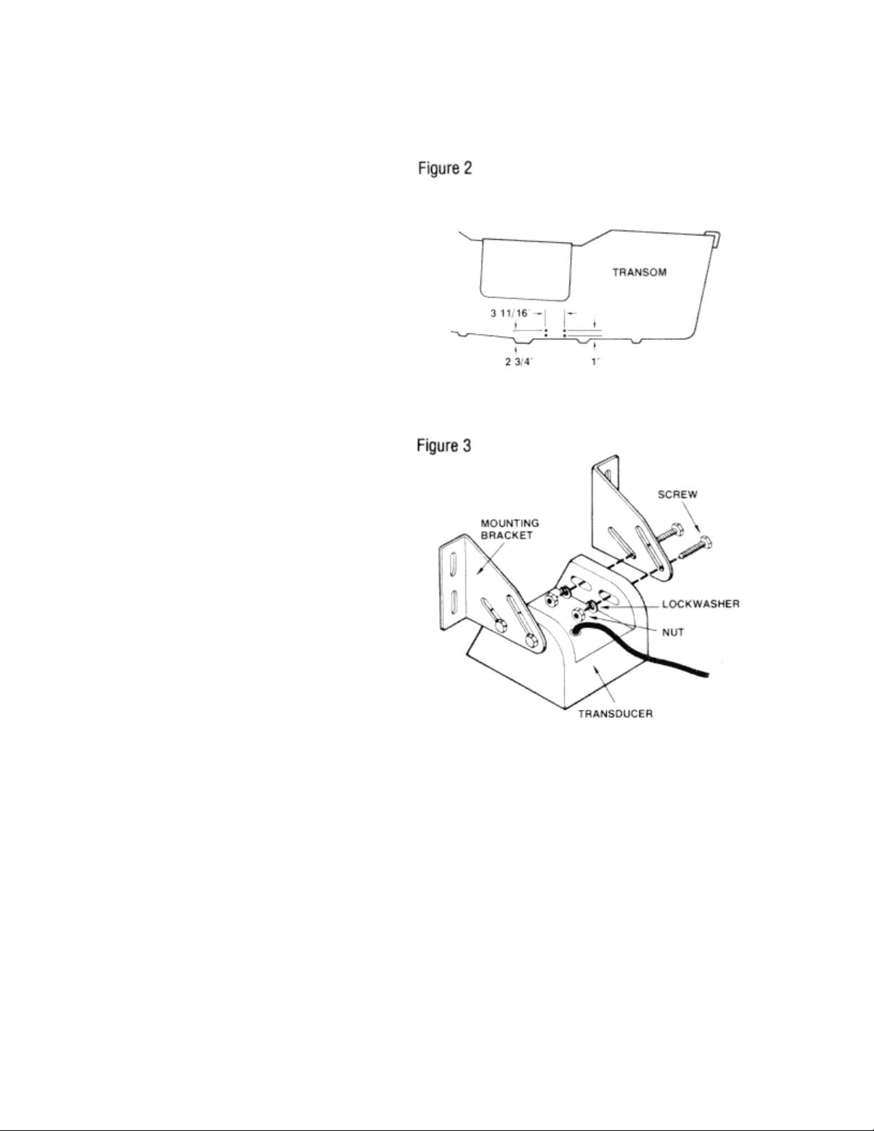
the transducer. The Humminbird CH Thirty
II is designed to operate with the 39 °
cone angle X2 -C transducer. A transom
transducer with mounting hardware is
provided as standard equipment with the
Humminbird Chart (Figure 3). This
transducer is designed to mount outside
the hull of the boat, but may be mounted
inside. However, for maximum
performance from your CH-3011, we
recommend mounting the transducer
outside. There might be circumstances
which would require a different style
transducer. If this is the case, we
recommend you contact a dealer
regarding availability.
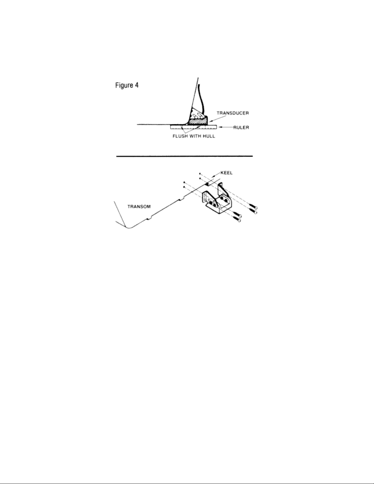
Determine a suitable location where a smooth flow of water will pass across the transducer face
(Figure 4). The bolts connecting the transducer to its mounting bracket are temporarily left
loosened to allow the transducer to be adjusted and positioned as shown in figure 4 top. Markings
can then be made for each of the four slots, which indicate the position of the screws used to
attach the mounting hardware (Figure 4 bottom). Drill four holes with a smaller diameter bit than
the screws being used. Lightly coat the screws with a silicone sealant to insure a tight, waterproof
bond and bolt the transducer into its proper position, with the beveled edge forward flush with the
bottom of the transom.
Air spaces should be sealed with a silicone sealant applied with a piece of stiff cardboard, taking
precautions against covering the "eye" of the transducer with the adhesive materials. Completed
quickly and efficiently, this type of installation should allow the instrument to give maximum
performance and definition.
The above installation will not give a suitable high-speed reading because of the transducer
angle. It is seldom that a high speed operation
Page 4
of a chart recorder is required. If high speed operation is desired, the rear of the transducer
should be lowered five degrees so that a smooth flow of water is experienced from the hull and
across the face of the transducer.
Note: Use the above method of transducer installation on all aluminum hulls. We do not
recommend an inside the hull mounting for any transducer being used with a chart recorder.
Loss of signal will be experienced any time a transducer for a chart recorder is mounted inside
the hull. N you find it necessary to use such an installation, we recommend the following
procedures be followed.
PROCEDURE FOR MOUNTING TRANSDUCER INSIDE HULL OF FIBERGLASS BOAT
Warning: In order to achieve proper results with this type installation, it is important that the
transducer be mounted by someone familiar with the use of Fiberglass resin. For this reason,
Techsonic Industries, Inc. will not be responsible for any damage due to the mounting of your
transducer in this manner.
1. Select as flat an area as possible near the aft end and center of boat where the hull is thin and
not double. If the bottom has a runner down the center of boat select an area to one side of the
runner, but as close to the runner as possible. 2. Clean the inside of the boat with lacquer thinner
in the area transducer is to be mounted. Outside of boat in this area should also be cleaned.
3. Put approximately one inch of water in the bottom of the boat.
4. Put transducer in the water. The bottom of the transducer should be in a flat area and should
be in good cont act with the bottom of the boat.
5. Operate the depth sounder with the boat stopped and operating at high speed. The transducer
may have to be moved in order to find an area where satisfactory operation is observed.
Page 5

6. When an area is found that produces satisfactory operation, mark the location of the
transducer.
7. Remove the water and transducer and clean the marked area and the bottom of the transducer
thoroughly with lacquer thinner. Sand the area thoroughly.
8. Mix an ample amount of fiberglass resin without causing it to bubble and pour it in the area the
transducer is to be mounted. The puddle should be larger than the bottom of the transducer.
9. Coat the bottom of the transducer with resin, then put it in the center of the puddle and push
down on the transducer while moving it around in a circular motion. This forces out any air
bubbles that may be trapped between the bottom of the transducer and the hull of the boat.
10. When the resin has cured the transducer is ready to operate. No water is now required in the
bottom of the boat and gas and oil that is spilled inside of the boat will not degrade performance
as it will if the transducer is placed only in water.
Caution: Do not use silicone seal or any soft adhesive to bond the transducer to the hull. This will
reduce the sensitivity of the unit.
You may choose to install the transducer yourself inside the hull of your FIBERGLASS boat. If so,
we recommend a good, two-part epoxy such as the one available in our Humminbird epoxy kit.
We recommend the following steps:
Any style of Humminbird transducer may be installed inside the hull.
After selecting a clean, flat area, lightly sand until a smooth finish is obtained.
The divider of the two-part Humminbird epoxy kit is then removed and the two parts mixed
together thoroughly for about five minutes. By clipping one corner of the plastic envelope, a liberal
amount of epoxy is put on the face of the transducer and spread evenly with the applicator
provided.
Any remaining epoxy is then applied to the inside hull where the transducer is to be installed and
by using a circular motion to squeeze out all air bubbles, the transducer is placed into position.
Finally, by pressing down firmly and holding for a few minutes the installation process is
completed cleanly and efficiently. Now properly affixed, the unit should function accurately at all
speeds.
There will be cases where it is necessary to use a through-the-hull transducer. We offer a sturdy,
durable bronze housing which is ideal. for large boats or special applications. This transducer
comes standard with 20 foot cable. It will be necessary to bore a 13116 inch hole through the hull.
If the hull has a curvature, it will be necessary to use a fairing block, shaped to fit the inside and
outside contour of the hull. These can be made of hardwood, casting resin or any other suitable
material. The fairing blocks should be cut or molded to the same dimensions as the head of the
transducer and thick enough to compensate for the contour of the hull. See Figure 5.
Caution: The hull of a wooden boat will tend to shrink when left out of the water for a prolonged
period of time. The nut should be hand tightened only, until the hull has had a chance to swell.
This should take about a week. The nut can then be tightened securely.
Page 6

INSTALLING THE POWER CABLE
The PC-3 power cable is supplied with your Chart. It has a red lead and black lead. Connect your
unit to a 12 volt DC power source. Red cable to a ( + ), black to negative (-). A THREE AMP SLOBLO AMP FUSE SHOULD BE INSTALLED BETWEEN THE RED CABLE AND POSITIVE POLE
ON YOUR 12 VOLT BATTERY.
Some boats are equipped with a fuse panel, generally located beneath the console. The power
source can be wired into the fuse panel, HOWEVER IT IS RECOMMENDED THAT THE POWER
CABLE BE WIRED DIRECTLY TO THE BATTERY.
Important: Although your power connector is made to plug in only one way, it can be forced on
incorrectly. N this is done, it may cause damage to your unit. So observe the offset of the power
plug pins and connect it to the control head accordingly.
Note: It is recommended that all cables for your chart (transducer and power) be positioned as far
away from all other wires and controls as possible. It is especially important that these cables be
located away from the ignition system to reduce the risk of interference in the unit.
Page 7

OPERATIONAL INSTRUCTIONS
Your Humminbird CH-THIRTY II has five control knobs located in the front of the unit. It is
suggested that you understand the function of each before at tempting to operate the unit.
1. Paper Speed: The first control knob located to the far left is the paper speed control. This
knob also serves as the “ON/Off” switch for the Chart. Turn this knob to the furthest counterclockwise position to turn the machine off.
Turn the knob until it clicks to start the unit. At this point, the paper will be advancing at the
FASTEST paper speed. To decrease the paper speed, turn the paper speed control
clockwise. It is possible that in turning the control to its furthest clockwise position the paper
will stop advancing. If this happens turn the control counter-clockwise until the paper starts
moving.
The shape of the targets can be controlled with this setting. The faster the paper advances,
the more spread out the signal and the easier it is to interpret. The following table will give a
guideline as to the approximate length of time it takes to consume a 50 foot roll of paper,
based on continuous operation.
Paper Speed Inches Approximate Continuous
per minute Setting Operation
3" 7 O'clock 3.3 hrs.
2112" 9 O'clock 4 hrs
2" 11 O'clock 5 hrs
1½" 1 O'clock 6.6 hrs.
1 " 2 O'clock 10 hrs.
Page 8

Note: While familiarizing yourself with the CH-THIRTY II, it is suggested you run the paper speed
this control for better target identification and bottom definition.
become illustrated by a light gray signal beneath the actual bottom signal.
as mud or weeds returning a weaker echo, the bottom signal will be considerably narrower.
between 9 and 10 o’clock for the first couple rolls of paper.
2. Depth Range: Your CH-THIRTY II offers a choice of four depth ranges. The upper most
position represents the 0-30 foot range. This is the shallow range on the unit and is excellent
for water less than 30 feet deep. Bass fishermen will find this an ideal range for most of their
fishing. An ideal setting for crappie, walleye. pike, muskie, and bluegill, as most of this fishing
will be done in shallow water.
The Second position is the 0-60 foot range. This could be the most widely used range on the
unit. A good all-around setting for the freshwater angler, the 60 foot range will give excellent
detail in shallow as well as moderately deep water. Great Lakes anglers will find this 60 foot
range ideal for early spring and late fall when the runs are shallow. The 0-120 foot range is
ideal for open water in both fresh and salt water situations. When water exceeds 60 feet deep
it is suggested the 120 foot scale be utilized. A good setting for trolling deep inland lakes and
excellent for Great Lakes operation. This will also be an ideal range for close offshore fishing
where the water is up to or slightly in excess of 100 feet deep.
The deep range on the unit is the 0-240 foot setting. This range will be best suited for inland
port navigation, deep Great Lakes fishing and for salt water angling.
You will not detect any change in the speed of the stylus belt when changing from the 030and 0-60 foot ranges. However, as you may switch to the 0-120 foot range, the belt speed
will slow down. It will slow down sgsin when you switch from the 0-120 to the o-240 foot
range. This change in belt speed will only affect the depth. It will have no effect on the speed
of the paper.
Your Humminbird chart paper is lined, and these lines can help pinpoint your target by
knowing the depth represented based upon the depth range of the unit. For example, on the
30 foot scale, the distance between the lines is 2 ½ feet. On the 60 foot scale the lines
represent five foot increments. On the 120 foot scale, each line represents a 10 foot
increment and on the 240 scale, the distance between represents 21 feet.
4. Noise Reject: This control will help eliminate interference due to external noise sources. If no
interference is evident, this knob should be rotated to the full counterclockwise position. If noise
interference is present, this control should be turned clockwise until the interference is just
eliminated and no more.
Remember that when you are using the noise reject, you are losing target resolution.
Resolution is the ability to detect distance between or separation of objects. Be sure that all
other depth sounders on the boat are turned off while operating the chart recorder.
5. White Line: The control on the far right is your white line feature. Your Chart is equipped with
The white line feature is off when the control knob is turned completely counter-clockwise. By
turning the knob clockwise the white line feature is activated. The display on the paper will
The wider the bottom signal, the harder the bottom composition. The softer the bottom, such
Your white line will help identify fish, especially large fish which are laying very near the
bottom. The fish will arc with the top being black and the lower part gray, while the bottom
itself will display a thin black line under the fish.
When attempting to locate a relatively hard surface in a soft bottom condition, the white line
Page 9

should be turned until the harder area is located. This area will return a gray signal as
opposed to the black for the softer bottom.
Note: In learning to operate your CH-THIRTY II, a recommended setting for the white line would
be 12 o’clock.
SURFACE NOISE
Most bodies of water, because of wind, wave action, or algae, will result in a degree of surface
noise or clutter which will be evident just below the zero mark on the chart paper. On those
bodies of water where there is virtually no wave action or algae, the amount of surface noise will
be minimal. A surface which is subjected to algae concentrations or a lot of wind and wave action,
such as white capping, will produce a lot of surface noise. Similar conditions are evident by the
turbulence created by an outboard engine. Crossing over the wake of an outboard will also cause
surface noise to be displayed. This condition can be altered by turning down the sensitivity
control, or by advancing to the next depth range. Some readings such as bait fish schools near
the surface might be effected by this condition, but it will not alter the appearance of the targets
beneath the surface clutter range. Surface feeding fish that are obscured by top surface clutter
will become evident by reducing the sensitivity, some loss of bottom echo will be experienced
however.
FRONT PANEL REMOVAL
The exclusive Humminbird amber viewing window is part of a delicate front panel which exposes
both the paper cartridge and the stylus belt. Either may be adjusted or changed through this front
paned by snapping open the two square closures located in the upper corners of the front panel
(Photo 1). This allows the panel to open forward. To remove the front panel from the unit,
simultaneously depress the two spring loaded pins at the bottom of the panel (Photo 2). It will
remove forward.
Page 10

CHANGING PAPER
Your Humminbird CH-THIRTY II has the most revolutionary paper system of any chart recorder
on the market. As a result, changing paper is a very simple operation.
After dropping or removing the viewing window, the stylus must be moved to the back of the
bottom pulley, out of the way, to avoid damage. (Photo1). With the thumb and forefinger squeeze
the release mechanism. The paper cartridge will pop forward and can be removed easily (photo
2).
Remove the used roll of paper from the cartridge. Also remove the nylon plugs from the ends of
the two paper rolls (Photo 3).
Page 11

Insert the plugs into the new roll of paper and take up core (Photo 4). Tape the end of the new roll
onto the take up core.
Note: Be sure the paper is taped on square. Roll several turns around the core., be sure it is
rolled straight on the core. This is important.
Stretch the paper tight across the front of the cartridge while positioning the rolls into place (Photo
5). Be sure the paper is tight against the face of the cartridge (Photo 6).
Page 12

Insert the cartridge into the unit and press firmly against the front until it clicks into position.
Note: The cartridge will go in either way. Make sure your printed edge of the chart paper is
always at the bottom of the cartridge.
Rotate the stylus belt downward by hand to insure that the paper is installed properly and will not
interfere with the stylus. Replace the front cover and you are ready to operate.
Page 13

Note: In cases of high humidity, it is recommended that the paper and cartridge be removed and
stored in a warm, dry place. This will prevent the paper from swelling, possibly causing a feed
problem.
Note: Spare cartridges are available. A pre-loaded cartridge will save time and can be changed
in a matter of seconds. We recommend at least one extra cartridge.
Page 14

CHANGING A STYLUS
After prolonged running a stylus may tend
to wear and require replacing. To replace
the stylus element, open the front cover
and rotate the stylus belt until the stylus
holder is in the center of the unit.
Your new stylus will come in two pieces.
There is a right hand element and a left
hand element. The right hand element
makes contact with the pick up bar to the
right of the stylus belt. The left hand
element makes contact with the paper
and does the printing (burning).
Follow steps A through D in figure 6 for
both elements.
A new stylus will on occasion have a
sharp tip which scratches the paper. A
small piece of fine abrasive paper should
be placed flat against the chart paper and
held there for 5 to 10 seconds while the
chart is running, so that the writing point
of the stylus is smoothed off.
Note: Periodically clean the bass stylus
bar on the right of the belt, occasionally
sanding lightly to prevent the stylus from
grooving the bar.
INTERFERENCE SOURCES
The chart recorder contains noise suppression circuits to make its performance as immune to
external noise sources as possible.
There are two groups of noise sources which may degrade performance in certain conditions.
These are electrical sources and mechanical sources.
Mechanical sources include such things as improper mounting of the transducer, causing water
turbulence at high speeds, appearing as degraded performance.
Also at high speeds some propellers cavitat e and produce vibration noise which will excite the
transducer and produce low level signals. Electrical sources include such obvious things as
ignition noise from engines. On some engines external gap spark plugs are used which are
partially troublesome. Electrical motors and generators can produce brush noise, and other
Page 15

installations do generate static electricity. High power radio transmitters can also have nuisance
effects.
V. H. F. Radios may also cause unit interference. A second depth sounder being operated
simultaneously to the chart will also cause interference. Turn all other depth sounders off while
operating the Chart Recorder.
Good grounding is a great help in reducing electrical noise. If you find you have a noise problem,
start linking all your items of electrical equipment to a central ground point such as the battery
terminal, with large gauge wire or braid (#6 or #8).
In the event that a particular interference problem cannot be corrected, it would be advisable to
contact a dealer or service center for assistance.
MAINTENANCE
A few simple maintenance steps can enhance the performance of your unit. While this piece of
equipment is designed to withstand a lot of physical abuse, it should still be treated as a delicate
instrument.
1. Keep your unit clean by wiping inside and out with a damp cloth.
2. Remove it from the boat when not in use. Store in a cool, dry place.
3. In extremely cold temperature it is suggested the unit be kept inside prior to its operation.
4. The transducer face should be kept clean free of buildup. Highway grime can coat t he face
while the boat is trailered. Briskly wipe the face with a damp cloth before launching the boat.
A light sanding with fine sandpaper prior to each use is also recommended.
5. Periodically inspect cables for nicks, cuts, or breaks. Such a nick can be repaired with
electrical tape.
6. Check connectors for corrosion, especially in salt water. A little baking soda and water on a
toothbrush will remove corrosive material.
7. Marine growth or buildup can be removed from the transducer face by scraping with a plastic
scraper. A light sanding is then suggested.
8. Keep grounding springs clean and free from carbon dust by wiping with a damp cloth.
9. Clean and sand stylus plate periodically to remove carbon and to preve nt groove from
forming.
 Loading...