

Humminbird CHIRP Radar Installation Manual
Humminbird®CHIRP Radar
Humminbird®CHIRP Radar
Installation Manual
Installation Manual
532523-1_B
Thank You!
Thank you for choosing Humminbird®, the #1 name in marine electronics. Humminbird has built its reputation
by designing and manufacturing top-quality, thoroughly reliable marine equipment. Your Humminbird is
designed for trouble-free use in even the harshest marine environment. We encourage you to read this
installation manual completely in order to get the full benefit from all the features and applications of your
Humminbird product.
Contact Humminbird Customer Service at humminbird.com or call 1-800-633-1468.
Important Information
Review the following important information before proceeding with the installation.
Certified Installation
WARNING! Humminbird recommends certified installation by a Humminbird approved installer. Contact
your Humminbird dealer for further details, and refer to the warranty information included at the end of this
manual.
WARNING! This product must be installed and operated in accordance with the instructions provided.
Failure to do so could result in personal injury, damage to your vessel and/or poor product performance.
CAUTION! Installation and radar tuning should only be performed by a qualified radar service technician.
Potential Ignition Source
WARNING! This product is NOT approved for use in hazardous and/or flammable atmospheres. Do NOT
install in a hazardous and/or flammable atmosphere (such as in an engine room or near fuel tanks).
High Voltages
HIGH VOLTAGE WARNING! Dangerously high voltages are present within the scanner unit. There
are no internal connections or adjustments necessary for installation. Do NOT remove any covers or
otherwise attempt to access internal components, unless specifically instructed in the documentation
provided. The cover should be removed only by a qualified radar service technician. Technicians must
exercise extreme care when working inside the unit.
WARNING! Connecting this product to a voltage supply greater than the specified maximum rating may
cause permanent damage to the unit. Refer to the Specifications section for voltage rating.
i
Radio Frequency and Microwave Radiation
DANGER: Microwave Radiation Hazard! The microwave energy radiated by a radar antenna is harmful
to humans, especially to one’s eyes. Do NOT look at the scanner from close range. Never look directly into an
open waveguide or into the path of radiation from an enclosed antenna. Make sure personnel are clear of
the scanner when it is powered on. Turn off the radar whenever it is necessary to work on the antenna unit
or on other equipment in the beam of the radar.
DANGER! Radar and other radio frequency radiation can upset cardiac pacemakers. If someone with a
cardiac pacemaker suspects abnormal operation, immediately turn off the equipment and move the person
away from the antenna.
CAUTION! For safety reasons, the radar must be installed above head height and out of range of personnel.
Positive Ground Systems
WARNING! Do not connect this unit to a system that has positive grounding.
Service and Maintenance
WARNING! Disassembly and repair of this electronic unit should only be performed by authorized service
personnel. Any modification of the serial number or attempt to repair the original equipment or accessories
by unauthorized individuals will void the warranty.
CAUTION! This product contains no user serviceable components. Please refer all maintenance and
repair to authorized Humminbird dealers. Unauthorized repair may affect your warranty.
Compass Safe Distance
WARNING! To prevent potential interference with the vessel's magnetic compasses, ensure an adequate
distance is maintained from the product.
NOTE: When choosing a suitable location for the product you should aim to maintain the maximum
possible distance from any compasses. Typically this distance should be at least 3 feet (1 m) in all directions.
However, for some smaller vessels it may not be possible to locate the product this far away from a compass.
In this situation, when choosing the installation location for your product, ensure that the compass is not
affected by the product when it is in a powered state.
Additional Warnings and Notes
WARNING! This device should not be used as a navigational aid to prevent collision, grounding, boat
damage, or personal injury. When the boat is moving, water depth may change too quickly to allow time for you
to react. Always operate the boat at very slow speeds if you suspect shallow water or submerged objects.
WARNING! The electronic chart in your Humminbird unit is an aid to navigation designed to facilitate the
use of authorized government charts, not to replace them. Only official government charts and notices to
mariners contain all of the current information needed for the safety of navigation, and the captain is
responsible for their prudent use and the safety of the vessel and its passengers.
NOTE: This product is specifically designed to be installed on boats and other means of maritime transport. If
your country forms part of the EU, please contact your dealer for advice before attempting to install elsewhere.
ii

NOTE: Some features discussed in this manual require a separate purchase, and some features are
only available on certain models. Every effort has been made to clearly identify those features. Please
read the manual carefully in order to understand the full capabilities of your model.
NOTE: The procedures and features described in this manual are subject to change without notice. This
manual was written in English and may have been translated to another language. Humminbird is not
responsible for incorrect translations or discrepancies between documents.
NOTE: Humminbird does not warrant that this product is error-free or that it is compatible with products
manufactured by any person or entity other than Humminbird.
NOTE: Humminbird is not responsible for damages or injuries caused by your use or inability to use the
product, by the interaction of the product with products manufactured by others, or by errors in information
utilized by the product supplied by third parties.
NOTE: Although the waterproof rating capacity of this product meets the stated IPX standard (refer to the
Specifications section), water intrusion and subsequent equipment failure may occur if the product is
subjected to commercial high-pressure washing. Humminbird will not warrant products subjected to highpressure washing.
NOTE: This product is protected by patents, design patents, patents pending, or design patents pending.
ATTENTION INTERNATIONAL CUSTOMERS: Products sold in the U.S. are not intended for use in
the international market. Humminbird international units provide international features and are designed to meet
country and regional regulations. Languages, maps, time zones, units of measurement, and warranty are examples of
features that are customized for Humminbird international units purchased through our authorized international
distributors.
To obtain a list of authorized international distributors, please visit our Web site at humminbird.com or contact
Humminbird Customer Service at (334) 687-6613.
iii

Compliance Statements
IEEE STATEMENT: This product complies with the IEEE C95.1 – 2005 – Standard for Safety Levels with respect
to Human Exposure to Radio Frequency Electromagnetic Fields, 3 kHz to 300 GHz.
ICNIRP GUIDELINES: When properly installed and operated, the use of this Radar conforms to: ICNIRP
Guidelines 1998 - International Commission on Non-Ionising Radiation Protection: Guidelines for limiting exposure to
time-varying electric, magnetic and electro-magnetic fields (up to 300 GHz) 1998.
DECLARATION OF CONFORMITY: Johnson Outdoors Marine Electronics, Inc. declares that this product
is compliant with the essential requirements of R&TTE directive 1999/5/EC.
IMO AND SOLAS: The equipment described within this document is intended for use on leisure marine boats
and workboats NOT covered by International Maritime Organization (IMO) and Safety of Life at Sea (SOLAS) Carriage
Regulations.
RADAR LICENSING: Installation and operation of this radar may be subject to individual licensing of the
equipment, operator or vessel. You are strongly advised to check with the requirements of the licensing authority of
your national administration. In case of any difficulties, contact your local Humminbird dealer.
FCC NOTICE – RADAR: Changes or modifications to this equipment not expressly approved in writing by
Johnson Outdoors Marine Electronics, Inc. could violate compliance with FCC rules and void the operator’s authority
to operate the equipment.
ENVIRONMENTAL COMPLIANCE STATEMENT: It is the intention of Johnson Outdoors Marine
Electronics, Inc. to be a responsible corporate citizen, operating in compliance with known and applicable
environmental regulations, and a good neighbor in the communities where we make or sell our products.
WEEE DIRECTIVE: EU Directive 2002/96/EC “Waste of Electrical and Electronic Equipment Directive (WEEE)”
impacts most distributors, sellers, and manufacturers of consumer electronics in the European Union. The WEEE
Directive requires the producer of consumer electronics to take responsibility for the management of waste from
their products to achieve environmentally responsible disposal during the product life cycle. WEEE compliance may
not be required in your location for electrical & electronic equipment (EEE), nor may it be required for EEE designed
and intended as fixed or temporary installation in transportation vehicles such as automobiles, aircraft, and boats. In
some European Union member states, these vehicles are considered outside of the scope of the Directive, and EEE
for those applications can be considered excluded from the WEEE Directive requirement.
This symbol (WEEE wheelie bin) on product indicates the product must not be disposed of with other
household refuse. It must be disposed of and collected for recycling and recovery of waste EEE. Johnson
Outdoors Marine Electronics, Inc. will mark all EEE products in accordance with the WEEE Directive. It is our
goal to comply in the collection, treatment, recovery, and environmentally sound disposal of those products;
however, these requirements do vary within European Union member states. For more information about where you
should dispose of your waste equipment for recycling and recovery and/or your European Union member state
requirements, please contact your dealer or distributor from which your product was purchased.
ROHS STATEMENT: Product designed and intended as a fixed installation or part of a system in a vessel may
be considered beyond the scope of Directive 2002/95/EC of the European Parliament and of the Council of 27
January 2003 on the restriction of the use of certain hazardous substances in electrical and electronic equipment.
iv

EMC Installation Guidelines
Humminbird equipment and accessories conform to the appropriate Electromagnetic Compatibility (EMC)
regulations, to minimize electromagnetic interference between equipment and minimize the effect such
interference could have on the performance of your system.
Correct installation is required to ensure that EMC performance is not compromised.
NOTE: In areas of extreme EMC interference, some slight interference may be noticed on the product.
Where this occurs the product and the source of the interference should be separated by a greater distance.
For optimum EMC performance, we recommend that wherever possible:
• Humminbird equipment and cables connected to it are:
– At least 3 feet (1 m) from any equipment transmitting or cables carrying radio signals (e.g. VHF
radios, cables and antennas). In the case of SSB radios, the distance should be increased to 7 feet
(2 m).
– More than 7 feet (2 m) from the path of a radar beam. A radar beam can normally be assumed
to spread 20 degrees above and below the radiating element.
• The product is supplied from a separate battery from that used for engine start. This is important to
prevent erratic behavior and data loss which can occur if the engine start does not have a separate
battery.
• Humminbird specified cables are used.
• Cables are not cut or extended, unless doing so is detailed in the installation manual.
NOTE: Where constraints on the installation prevent any of the above recommendations, always ensure
the maximum possible separation between different items of electrical equipment, to provide the best
conditions for EMC performance throughout the installation.
HELIX®, Humminbird®, ONIX®, and SOLIX® are registered trademarks of Johnson Outdoors Marine Electronics, Inc.
Adobe, Acrobat, Adobe PDF, and Reader are either registered trademarks or trademarks of Adobe Systems Incorporated in the United
States and/or other countries.
© 2017 Johnson Outdoors Marine Electronics, Inc. All rights reserved.
v

Table of Contents
Thank You i
Important Information i
Introduction 1
1. Installation Preparation 2
1. Review the Box Contents . . . . . . . . . . . . . . . . . . . . . . . . . . . . . . . . . . . . . . . . . . . . . . . . . . . . . . . . . . . . . . . . . 2
2. Determine the Cable Requirements. . . . . . . . . . . . . . . . . . . . . . . . . . . . . . . . . . . . . . . . . . . . . . . . . . . . . . . . . 3
3. Create a Schematic Diagram . . . . . . . . . . . . . . . . . . . . . . . . . . . . . . . . . . . . . . . . . . . . . . . . . . . . . . . . . . . . . . 3
4. Clear the Mounting Holes . . . . . . . . . . . . . . . . . . . . . . . . . . . . . . . . . . . . . . . . . . . . . . . . . . . . . . . . . . . . . . . . 4
2. Choose the Mounting Location 5
3. Test Route the Cables 11
4. Install the Scanner 12
1. Prepare the Mounting Location . . . . . . . . . . . . . . . . . . . . . . . . . . . . . . . . . . . . . . . . . . . . . . . . . . . . . . . . . . . 12
2. Connect the Power and Data Cables to the Radar Scanner . . . . . . . . . . . . . . . . . . . . . . . . . . . . . . . . . . . . . 13
3. Install the Radar Scanner . . . . . . . . . . . . . . . . . . . . . . . . . . . . . . . . . . . . . . . . . . . . . . . . . . . . . . . . . . . . . . . . 15
5. Route the Cables 17
1. Route the Power and Data Cables . . . . . . . . . . . . . . . . . . . . . . . . . . . . . . . . . . . . . . . . . . . . . . . . . . . . . . . . . 17
6. Connect to Power and Ethernet 18
1. Determine Your Fuse and Thermal Breaker Requirement . . . . . . . . . . . . . . . . . . . . . . . . . . . . . . . . . . . . . . . 18
2. Connect to Power . . . . . . . . . . . . . . . . . . . . . . . . . . . . . . . . . . . . . . . . . . . . . . . . . . . . . . . . . . . . . . . . . . . . . . 19
3. Connect to the Control Head . . . . . . . . . . . . . . . . . . . . . . . . . . . . . . . . . . . . . . . . . . . . . . . . . . . . . . . . . . . . . 20
7. Test the Installation 22
Mechanical Checks. . . . . . . . . . . . . . . . . . . . . . . . . . . . . . . . . . . . . . . . . . . . . . . . . . . . . . . . . . . . . . . . . . . . . . . 22
Power On the Control Head . . . . . . . . . . . . . . . . . . . . . . . . . . . . . . . . . . . . . . . . . . . . . . . . . . . . . . . . . . . . . . . . 22
Two Year Limited Warranty & Service Policy 23
Maintenance 26
Troubleshooting 27
Specifications 28
Contact Humminbird 34
vi


Introduction
The Humminbird Radar scanner is a compact, solid-state radar that utilizes CHIRP pulse compression for
improved range resolution. Connect the Radar scanner to your Humminbird control head to view a map-like
representation of the area surrounding your vessel, enabling you to identify other vessels, buoys, and land
features such as coastlines and hills.
The Humminbird Radar scanner includes the following features:
• Solid-state technology (no magnetron) for improved efficiency and quick start-up.
• Range performance up to 24 nm (dependent on installation location).
• CHIRP pulse compression for improved target range resolution and reduced background noise.
• Radar image display and control via compatible Humminbird control head.
• 24 RPM scanner rotation.
• Low power consumption.
NOTE: For operations information, see your control head operations manual, which is available for download
at humminbird.com.
Installation Overview
This manual will guide you through the following installation requirements for the Humminbird Radar
scanner:
• Preparing for Installation
• Selecting the Mounting Location
• Installing the Radar Scanner
• Connecting to Power and Ethernet
Multiple Radar Installation: Only one radar scanner can be used at any one time, per networked system.
If you have more than one radar scanner installed on your boat and want to use them at the same time, the
control heads to which the scanners are connected must NOT be networked together.
CAUTION! Installation and radar tuning should only be performed by a qualified radar service technician.
1
Overview
1. Installation Preparation
Following are instructions for the installation of this accessory. Before you start installation, we encourage
you to read these instructions carefully in order to get the full benefit from your Humminbird accessory.
Supplies: In addition to the hardware included in this box, you will need a separate 12 or 24 VDC power
supply from that used for engine start, adhesive tape, a powered hand drill and various drill bits, various
hand tools, safety glasses, and a dust mask.
NOTE: It is important that you have read and understood the warnings and cautions provided in the
Important Information section of this manual before proceeding with the installation.
NOTE: A separate 12/24 VDC power supply is required for the Radar scanner installation to prevent erratic
behavior and data loss, which can occur if the engine start does not have a separate power supply.
1. Review the Box Contents
Also, see the Specifications section for additional product information.
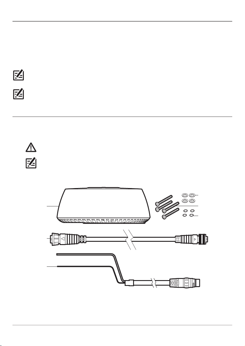
1. Unpack the box and confirm the contents with the illustration shown below.
CAUTION! Do not remove the cover from the unit. There are no connections or adjustments inside
the unit that are needed for installation or operation.
NOTE: Product supplies and features are subject to change without notice.
Parts Supplied
(1) Radar scanner
(1) AS EC M12
to RM data cable
(32.8 ft [10 m])
(1) power cable
(32.8 ft [10 m])
Installation Preparation
(4) flat washers
(4) M8 mounting bolts
(4) spring washers
2
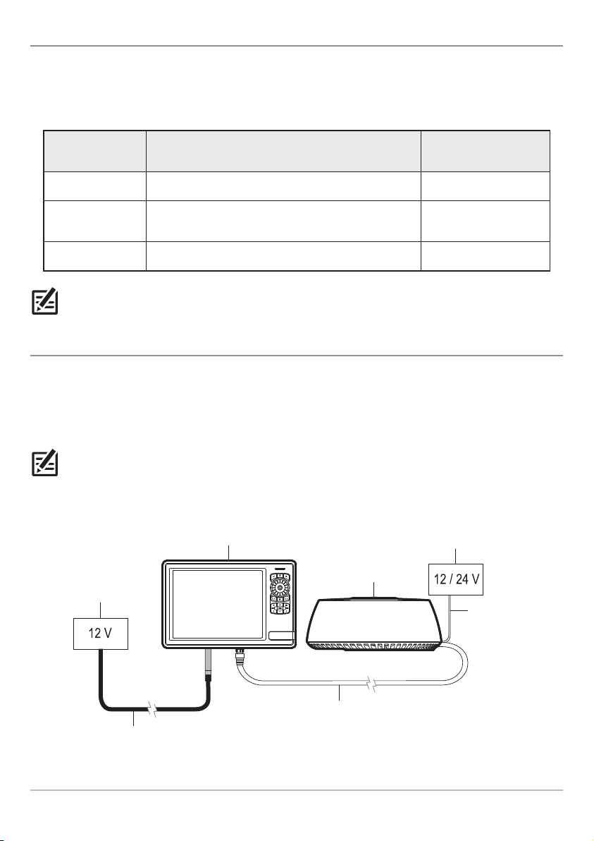
2. Determine the Cable Requirements
Depending on your Humminbird model and network configuration, you may need to purchase additional
accessories to connect your Radar scanner to your control head or Ethernet network. Before starting the
installation, determine whether you will need to purchase Ethernet Adapter Cables or extension cables.
Also, see Connect to Power and Ethernet for more information.
Hardware Cable Requirement to Connect to Radar Scanner Voltage Requirements
ONIX/SOLIX No additional cables required. 12 VDC
HELIX
Separate purchase AS EC QDE Ethernet Adapter
Cable is required.
12 VDC
Ethernet Switch No additional cables required. 12 or 24 VDC
NOTE: To purchase Ethernet Accessory Cables, extension cables, or the Ethernet Switch, visit our Web site
at humminbird.com or call Humminbird Customer Service at 1-800-633-1468.
3. Create a Schematic Diagram
A schematic diagram is an essential part of planning any installation. It is also useful for any future additions
or maintenance of the system. The diagram should include the following:
• Location of all components
• Cable types, routes, and lengths.
NOTE: Confirm that you have read and understood the warnings and cautions provided in the Important
Information section before proceeding with the installation.
Example of a Schematic Diagram with a Direct Connection to the Control Head
separate 12/24 V
power supply
Radar scanner
power cable
(32.8 ft [10 m])
control head
power supply
ONIX control head
Radar scanner
control head power cable
(6 ft [2 m])
AS EC M12 to RM data cable (included)
(32.8 ft [10 m])
3
Installation Preparation
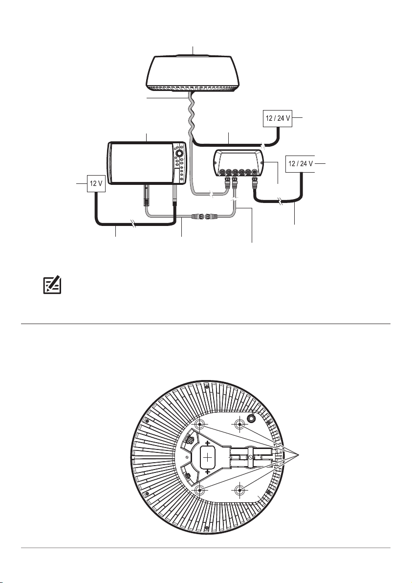
Example of a Schematic Diagram with an Ethernet Switch Connection
Radar scanner
AS EC M12 to RM data cable
(32.8 ft [10 m])
Radar scanner power
HELIX control head
control head
power supply
control head power cable
(lengths vary per model)
NOTE: Cable lengths and power voltage requirements vary per model. Refer to the installation guides
included with your products for additional information.
AS EC QDE adapter cable
(12 in [304.8 mm])
(separate purchase required)
cable (32.8 ft [10 m])
Ethernet Switch
Ethernet cable
(separate purchase required)
separate 12/24 V
power supply
Ethernet Switch
power supply
Ethernet Switch
power cable
4. Clear the Mounting Holes
1. Invert the scanner.
2. Confirm the four mounting holes are clear so they can accept the bolts.
Clearing the Mounting Holes
Installation Preparation
4
(4) mounting holes
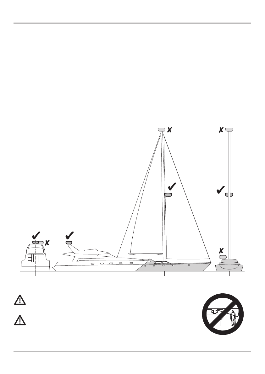
2. Choose the Mounting Location
It is important to consider the following information when installing the Radar scanner on the vessel. The
Radar scanner must be mounted where it is:
• Near the vessel's centerline
• Above head height
• Clear of large objects such as the flybridge, large engine stacks, searchlights, horns, masts, etc.
• At least 3 feet (1 m) from a magnetic compass or other scanners
• Away from heat and fumes
• On a stable platform that is capable of securely supporting the scanner under seagoing conditions
• Easily accessible
Determining the Mounting Location
rear view side view side view rear view
WARNING! Do NOT install the radar in a location that exposes passengers and
crew to the radar beam. Do NOT mount the radar where it could radiate on any person.
CAUTION! Working at higher elevations may become necessary while installing
the scanner unit. Observe safety measures and take sufficient precautions to avoid
personal injury or damage to the equipment.
5
Installation Preparation
 Loading...