

Humminbird ASETH5PXG Installation Manual
1
ETHERNET SWITCH Installation Guide
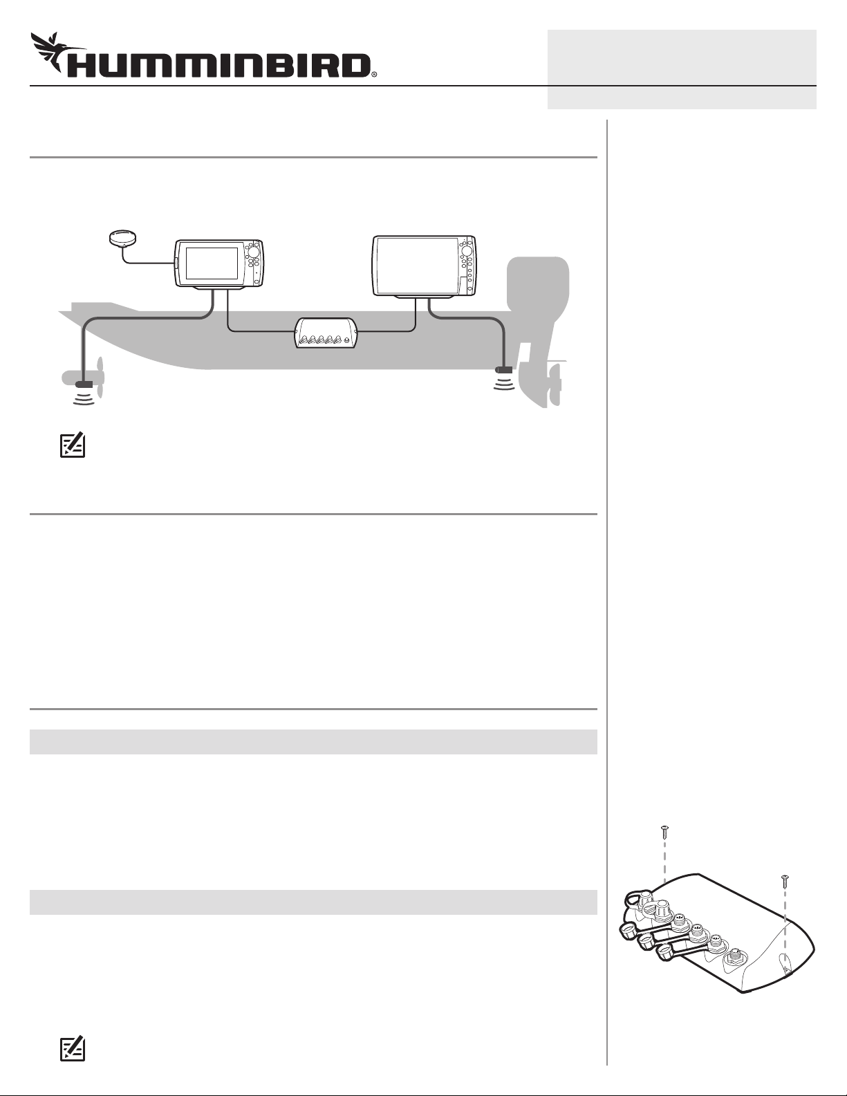
OVERVIEW
he Ethernet Switch allows you to share sonar and navigation data from up to five Humminbird®
T
control heads.
Example of an Ethernet Network Con figuration
NOTE: This accessory can only be used with Humminbird control heads that have Ethernet
capability. Contact Customer Service at humminbird.com or call 1-800-633-1468 for more
information.
531951-2_D
PREPARATION
Following are instructions for the installation of this accessory. Before you start installation, we
encourage you to read these instructions carefully in order to get the full benefit from your
Humminbird accessory.
Supplies: In addition to the hardware supplied with your installation kit, you will need a powered hand
drill,
a 9/64" drill bit,
cables.
Customer Service: To purchase cables, or if you have any questions about the installation, visit our Web
site at humminbird.com or call Customer Service at 1-800-633-1468.
a Phillips screwdriver, a level, a pencil, and optional-purchase Humminbird Ethernet
INSTALLATION
|
Determining the Mounting Location
1
The Ethernet Switch is designed to mount on any flat, level surface of your boat. Prior to installation,
you must first determine where to mount the Ethernet Switch.
1. Use a level to locate a suitable, flat area to mount the Ethernet Switch.
2. Place the Ethernet Switch in the desired mounting location and test the length of the Ethernet
cables (separate purchase required) to ensure that each cable will reach the Ethernet Switch.
|
Installing the Ethernet Switch
2
Installing the Ethernet Switch
Once you have determined the mounting location, perform the following procedures to install the
Ethernet Switch on your boat.
1. Set the Ethernet Switch in place on the mounting surface. Mark the two mounting screw
locations with a pencil.
2. Set the Ethernet Switch aside, and drill the two mounting holes using a 9/64” drill bit.
NOTE: On fiberglass hulls, it is best to use progressively larger drill bits to reduce the
chance of chipping or flaking the outer coating.
GROUNDGROUND
POSITIVEPOSITIVE
2
ETHERNET SWITCH Installation Guide
NOTE: If the mounting surface is thin or made of a lightweight material, you may need to add
reinforcing material below the mounting surface in order to support the Ethernet Switch.
3. Place the Ethernet Switch on the mounting surface and align the screw holes with the drilled
ounting holes. Insert the two #8 screws (included) through the screw holes and into the
m
drilled mounting holes, and hand-tighten using a Phillips screwdriver. Hand-tighten only!
NOTE: Apply marine-grade silicone caulk or sealant (separate purchase required) to both
screws and drilled holes as needed to protect your boat from water damage.
|
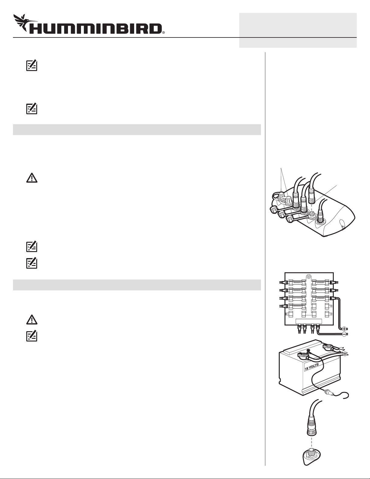
Connecting the Ethernet Cables
3
Up to five Ethernet cables (separate purchase required) can be connected to the Ethernet Switch at
one time. There is no specific order in which the cables have to be connected. Refer to your Ethernet
Networking manual and control head installation guide for the correct procedure for connecting the
cables to the control head.
CAUTION! Do NOT mount the cables where the connectors could be submerged in water or
flooded. If cables are installed in a splash-prone area, it may be helpful to apply dielectric
grease to the inside of the connectors to prevent corrosion. Dielectric grease can be
purchased separately from a general hardware or automotive store.
1. Confirm that the Ethernet cable is connected to the control head.
2. Unscrew an Ethernet port cover from the Ethernet Switch. Plug the end of the Ethernet cable
into the port.
531951-2_D
Connecting the Ethernet Cables
to the Ethernet Switch
Keep port covers fastened
over unused ports.
screw nut
3. Hand-tighten the screw nut to secure the cable connection.
NOTE: The connector ports are keyed to prevent reversed installation, so be careful not to
force the connector into the port.
NOTE: Make sure the port covers are tightly fastened over any unused connector ports.
Connectors that are left exposed may corrode.
|
Connecting the Power Cable
4
The Ethernet Switch power cable (included) can be connected to the electrical system of the boat at
two locations: a fuse panel (usually located near the console) or directly to the battery.
CAUTION! Make sure that the power cable is disconnected from the Ethernet Switch at the
beginning of this procedure.
NOTE: Humminbird is not responsible for over-voltage or over-current failures. The Ethernet
Switch must have adequate protection through the proper selection and installation of a
3 amp fuse (separate purchase required).
1a. If a fuse terminal is available, use crimp-on type electrical connectors (not included) that
match the terminal on the fuse panel. Depending on your control head model, attach the black
wire to ground (-) and the red wire to positive (+) 12 VDC power. Install a 3 amp fuse (not
included) for the protection of the accessory. Humminbird is not responsible for over-voltage
or over-current failures.
or...
Connecting the Power Cable
1b. If you need to wire the power cable directly to a battery, obtain and install an inline fuse holder
and a 3 amp fuse (not included) for the protection of the accessory. Attach the black wire to
ground (-) and the red wire to positive (+). Humminbird is not responsible for over-voltage or
over-current failures.
2. Connect the end of the power cable to the port labeled POWER on the Ethernet Switch. The
ports are keyed to prevent reversed installation, so be careful not to force the connector into
the connector port.
3. Hand-tighten the screw nut to secure the cable connection.
 Loading...