

Page 1

Humminbird®Radar
Humminbird®Radar
Installation and Operations Manual
Installation and Operations Manual
531986-1_A
Page 2

Thank You
Thank you for choosing Humminbird®, America's #1 name in fishfinders. Humminbird® has built its reputation
by designing and manufacturing top-quality, thoroughly reliable marine equipment. Your Humminbird® is
designed for trouble-free use in even the harshest marine environment. We encourage you to read this
installation and operations manual completely in order to getfull benefit from all the features and applications
of your Humminbird® product.
Contact our Customer Resource Center at 1-800-633-1468 or visit our Web site at humminbird.com.
Warnings
HIGH VOLTAGE WARNING! Dangerously high voltages are present within the scanner unit. There
are no internal connections or adjustments necessary for installation. The cover should be removed
only by a qualified radar service technician. Technicians must exercise extreme care when working
inside the unit. Always remove power before removing the cover. Some capacitors may take several
minutes to discharge, even after switching off the radar. Before touching the magnetron or any high
voltage components, ground them with a clip lead.
CAUTION! Installation and radar tuning should only be performed by a qualified radar service
technician.
DANGER: MICROWAVE RADIATION HAZARD! The microwave energy radiated by a radar antenna
is harmful to humans, especially to one’s eyes. Never look directly into an open waveguide or into
the path of radiation from an enclosed antenna. Radar and other radio frequency radiation can upset
cardiac pacemakers. If someone with a cardiac pacemaker suspects abnormal operation,
immediately turn off the equipment and move the person away from the antenna. Turn off the radar
whenever it is necessary to work on the antenna unit or on other equipment in the beam of the radar.
WARNING! How to interpret the radar display is not included in this manual. The captain is responsible
for the proper use of radar and the safety of the vessel and its passengers.
WARNING! This device should not be used as a navigational aid to prevent collision, grounding, boat
damage, or personal injury. When the boat is moving, water depth may change too quickly to allow
time for you to react. Always operate the boat at very slow speeds if you suspect shallow water or
submerged objects.
WARNING! The electronic chart in your Humminbird® unit is an aid to navigation designed to
facilitate the use of authorized government charts, not to replace them. Only official government
charts and notices to mariners contain all of the current information needed for the safety of
navigation, and the captain is responsible for their prudent use.
WARNING! Disassembly and repair of this electronic unit should only be performed by authorized
service personnel. Any modification of the serial number or attempt to repair the original equipment
or accessories by unauthorized individuals will void the warranty.
WARNING! This product contains chemicals known to the State of California to cause cancer and/or
reproductive harm.
i
Page 3

NOTE: This product is specifically designed to be installed on boats and other means of maritime transport. If your country
forms part of the EU, please contact your dealer for advice before attempting to install elsewhere.
NOTE: Some features discussed in this manual require a separate purchase, and some features are only available on
certain models. Every effort has been made to clearly identify those features. The illustrations in this manual may look
different than your display, but your model will operate in a similar way. Please read the manual carefully in order to
understand the full capabilities of your model.
ENVIRONMENTAL COMPLIANCE STATEMENT: It is the intention of Humminbird® to be a responsible corporate citizen,
operating in compliance with known and applicable environmental regulations, and a good neighbor in the communities
where we make or sell our products.
ROHS STATEMENT: Product designed and intended as a fixed installation or part of a system in a vessel may be considered
beyond thescope of Directive2002/95/EC of the European Parliament and of the Council of 27 January 2003 on the restriction
of the use of certain hazardous substances in electrical and electronic equipment.
800 Series™, 900 Series™, 1100 Series™, Humminbird®, and X-Press™ Menu are trademarked by or registered trademarks of
Johnson Outdoors Marine Electronics, Inc.
© 2011 Johnson Outdoors Marine Electronics, Inc., Eufaula AL, USA. All rights reserved.
ii
Page 4

Table of Contents
Thank You i
Warnings i
How Radar Works 1
Prepare for Installation 2
Choose the Mounting Location 4
Adjust for Obstacles . . . . . . . . . . . . . . . . . . . . . . . . . . . . . . . . . . . . . . . . . . . . . . . . . . . . . . . . . . . . . . . . . . . . . . . . 6
Shifting from the Center Line . . . . . . . . . . . . . . . . . . . . . . . . . . . . . . . . . . . . . . . . . . . . . . . . . . . . . . . . . . . . . . . . . 6
Obtaining Sufficient Dip Angle. . . . . . . . . . . . . . . . . . . . . . . . . . . . . . . . . . . . . . . . . . . . . . . . . . . . . . . . . . . . . . . . 7
Mounting Base . . . . . . . . . . . . . . . . . . . . . . . . . . . . . . . . . . . . . . . . . . . . . . . . . . . . . . . . . . . . . . . . . . . . . . . . . . . . 7
Installation 8
AS 12RD2KW: Scanner Installation . . . . . . . . . . . . . . . . . . . . . . . . . . . . . . . . . . . . . . . . . . . . . . . . . . . . . . . . . . . . 8
AS 21RD4KW: Scanner Installation . . . . . . . . . . . . . . . . . . . . . . . . . . . . . . . . . . . . . . . . . . . . . . . . . . . . . . . . . . . 10
Connect Power . . . . . . . . . . . . . . . . . . . . . . . . . . . . . . . . . . . . . . . . . . . . . . . . . . . . . . . . . . . . . . . . . . . . . . . . . . . 12
Start/Stop Radar Transmission 15
Start Transmission or Start Timed Transmission. . . . . . . . . . . . . . . . . . . . . . . . . . . . . . . . . . . . . . . . . . . . . . . . . . 15
Set Timed Transmission Settings. . . . . . . . . . . . . . . . . . . . . . . . . . . . . . . . . . . . . . . . . . . . . . . . . . . . . . . . . . . . . . 15
Stop Transmission . . . . . . . . . . . . . . . . . . . . . . . . . . . . . . . . . . . . . . . . . . . . . . . . . . . . . . . . . . . . . . . . . . . . . . . . . 15
Radar Configuration (installation and repair only) 16
Open the Radar Installation Menu . . . . . . . . . . . . . . . . . . . . . . . . . . . . . . . . . . . . . . . . . . . . . . . . . . . . . . . . . . . . 16
Tune the Radar. . . . . . . . . . . . . . . . . . . . . . . . . . . . . . . . . . . . . . . . . . . . . . . . . . . . . . . . . . . . . . . . . . . . . . . . . . . . 17
Adjust the Trigger Delay . . . . . . . . . . . . . . . . . . . . . . . . . . . . . . . . . . . . . . . . . . . . . . . . . . . . . . . . . . . . . . . . . . . . 17
Set the Main Bang Suppression . . . . . . . . . . . . . . . . . . . . . . . . . . . . . . . . . . . . . . . . . . . . . . . . . . . . . . . . . . . . . . 18
Set the Sector Blanking Range . . . . . . . . . . . . . . . . . . . . . . . . . . . . . . . . . . . . . . . . . . . . . . . . . . . . . . . . . . . . . . . 18
Adjust the Heading Line . . . . . . . . . . . . . . . . . . . . . . . . . . . . . . . . . . . . . . . . . . . . . . . . . . . . . . . . . . . . . . . . . . . . 19
Radar Operations 20
Menus. . . . . . . . . . . . . . . . . . . . . . . . . . . . . . . . . . . . . . . . . . . . . . . . . . . . . . . . . . . . . . . . . . . . . . . . . . . . . . . . . . . 20
Views 22
Radar View . . . . . . . . . . . . . . . . . . . . . . . . . . . . . . . . . . . . . . . . . . . . . . . . . . . . . . . . . . . . . . . . . . . . . . . . . . . . . . . 22
Chart/Radar Combo View (GPS Required) . . . . . . . . . . . . . . . . . . . . . . . . . . . . . . . . . . . . . . . . . . . . . . . . . . . . . . 23
iii
Page 5

Table of Contents
Radar Display Settings 24
Adjust Interference Rejection . . . . . . . . . . . . . . . . . . . . . . . . . . . . . . . . . . . . . . . . . . . . . . . . . . . . . . . . . . . . . . . . 24
Change the Radar Display Palette. . . . . . . . . . . . . . . . . . . . . . . . . . . . . . . . . . . . . . . . . . . . . . . . . . . . . . . . . . . . . 24
Display Range Rings . . . . . . . . . . . . . . . . . . . . . . . . . . . . . . . . . . . . . . . . . . . . . . . . . . . . . . . . . . . . . . . . . . . . . . . 24
Adjust Radar Settings 25
Adjust STC Settings . . . . . . . . . . . . . . . . . . . . . . . . . . . . . . . . . . . . . . . . . . . . . . . . . . . . . . . . . . . . . . . . . . . . . . . . 25
Adjust Gain Settings . . . . . . . . . . . . . . . . . . . . . . . . . . . . . . . . . . . . . . . . . . . . . . . . . . . . . . . . . . . . . . . . . . . . . . . 25
Adjust FTC Settings . . . . . . . . . . . . . . . . . . . . . . . . . . . . . . . . . . . . . . . . . . . . . . . . . . . . . . . . . . . . . . . . . . . . . . . . 25
Adjust the Transmission Range. . . . . . . . . . . . . . . . . . . . . . . . . . . . . . . . . . . . . . . . . . . . . . . . . . . . . . . . . . . . . . . 25
EBL/VRM 26
Create an EBL/VRM with the Cursor (GPS Required). . . . . . . . . . . . . . . . . . . . . . . . . . . . . . . . . . . . . . . . . . . . . . 26
Create an EBL/VRM with the X-Press™ Menu . . . . . . . . . . . . . . . . . . . . . . . . . . . . . . . . . . . . . . . . . . . . . . . . . . . 27
Edit an EBL/VRM Pair. . . . . . . . . . . . . . . . . . . . . . . . . . . . . . . . . . . . . . . . . . . . . . . . . . . . . . . . . . . . . . . . . . . . . . . 28
Delete an EBL/VRM . . . . . . . . . . . . . . . . . . . . . . . . . . . . . . . . . . . . . . . . . . . . . . . . . . . . . . . . . . . . . . . . . . . . . . . . 28
Specifications 29
Contact Humminbird® 31
iv
Page 6

Page 7
How Radar Works
Si
d
e
L
o
b
e
L
e
v
e
l
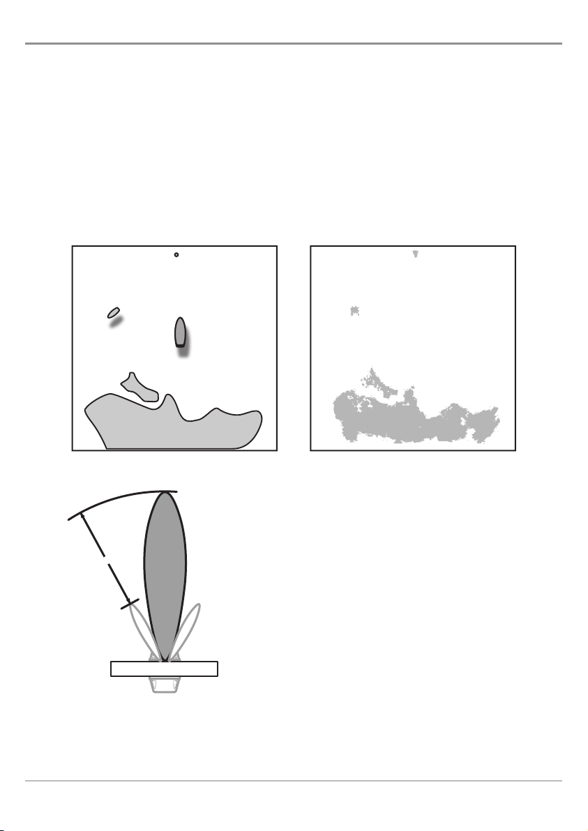
The word “radar” is an acronym for “Radio Detecting And Ranging.” A radio transmitter sends a quick
microwave pulse, and then a receiver listens for that signal’s echo when it is bounced back from something
in its path. The returning signal is processed by a computer to determine its relative distance, position, and
bearing. This information is graphically displayed on a view for you to see. Other boats or ships, navigational
markers, and landmasses are referred to as targets.
By knowing how long it takes for a signal to return, the distance to a target can be determined. As the radar
antenna scans through a 360-degree rotation, it can show where the target is relative to your position. By
repeated scans, you can see which direction another boat is moving. How a target is displayed on the screen
depends on the target’s height and size as well as its material and shape.
Boat and Surrounding Targets Radar Display
How radar will perform is mostly determined by the antenna
or scanner. Increasing the size of the antenna improves
long-range performance and target discrimination, or the
ability to distinguish two separate targets at a distance. The
critical factors are the antenna’s beam width and side lobe
level.Typically, a radar antenna will radiate a tightly focused
beam from the front of the array. The longer the antenna
array is, the narrower the beam width will be. Additionally,
it will also emit smaller amounts of energy to each side. The
lower the side lobe level, the less the effect of a false echo.
WARNING!
this manual. The captain is responsible for the proper use of radar
and the safety of the vessel and its passengers.
1
How to interpret the radar display is not included in
How Radar Works
Page 8
Prepare for Installation
Before you begin installation, it is important to review the installation instructions and check the hardware
to confirm that you have all of the required equipment.
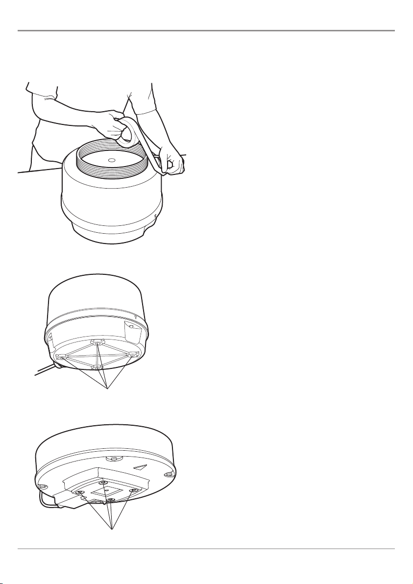
Securing the Cable with Tape
Clearing the Mounting Holes (AS 12RD2KW)
Supplies: In addition to the hardware included in this
box, you will also need vinyl tape, a powered hand drill
and various drill bits, various hand tools, safety glasses,
a dust mask, and sealant.
1. Unpack the box and confirm the contents
with the illustration shown on the next
page.
2. Coil the cable and place the cable on top of
the scanner. Secure the cable with tape.
3. Invert the scanner and make sure the four
mounting holes are clear to accept bolts.
4 Mounting Holes
Clearing the Mounting Holes (AS 21RD4KW)
4 Mounting Holes
Installation
2
Page 9
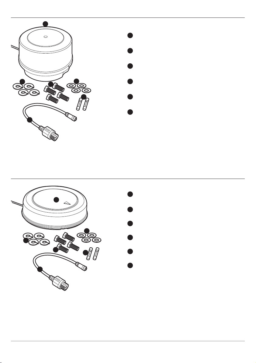
AS 12RD2KW: Box Contents*
A
A
Scanner/Antenna (1)
B
Lock Washers (4)
C
Bolts, Hex Metric M8 x 25mm (1 in.) (4)
B
F
NOTE: Do not remove the cover from the unit. There are no connections or adjustments inside the unit that are needed for
installation or operation. The cable must remain attached.
C
D
E
D
Flat Washers (4)
E
5A Fuses (2)
F
Adapter Cable (1)
AS 21RD4KW: Box Contents*
A
A
D
B
C
E
Scanner/Antenna (1)
B
Lock Washers (4)
C
Bolts, Hex Metric M10 x 25mm (1 in.) (4)
D
Flat Washers (4)
E
8A Fuses (2)
F
F
NOTE: Do not remove the cover from the unit. There are no connections or adjustments inside the unit that are needed for
installation or operation. The cable must remain attached.
*Box contents and features are subject to change without notice.
Adapter Cable (1)
3
Installation
Page 10
Choose the Mounting Location
It is important to consider the following information when installing the scanner on the boat. Also, see Adjust
for Obstacles for more information.
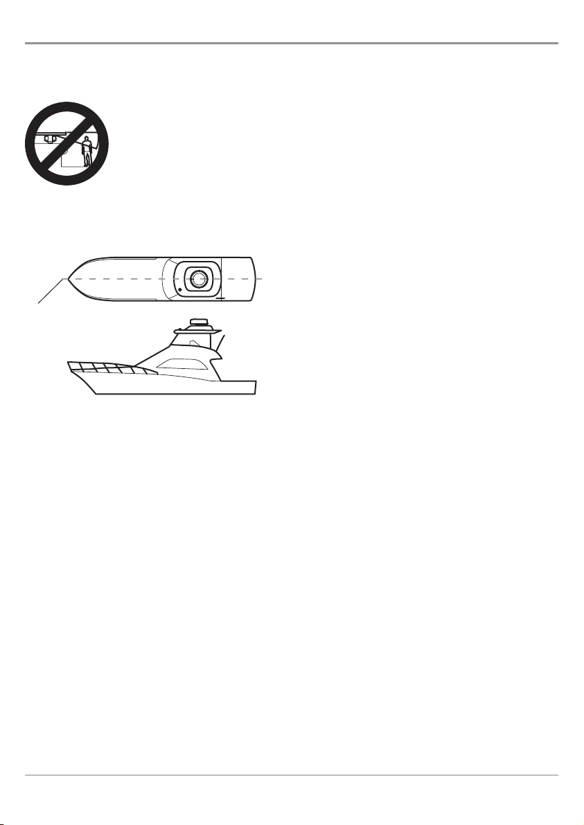
WARNING!
Do NOT install the radar in a location that exposes passengersand crew to the radar beam. Do NOT mount
the radar where it could radiate on any person.
CAUTION! Working at higher elevations may become necessary while installing the scanner unit. Observe safety measures
and take sufficient precautions to avoid personal injury or damage to the equipment.
Center Line: The scanner unit should be mounted on
the center line of your boat in a location that has an
Center line
of boat
unobstructed view forward and is as clear as possible
the rest of the way around the unit.
Height: Choose a location as high as practical to
improve maximum range; however, keep in mind that
minimum range objects may be overlooked if mounted
too high.
Unobstructed View: Position the unit forward of large
structures and exhaust stacks. Large structures or
stacks cause blind spots. Contamination from engine
exhaust on the scanner housing reduces radar
performance.
Installation
• Antennas for GPS, radio communication, or other
equipment should not be located in the radar
beam.
• Use non-metallic extension poles to move the
active area of antennas above the radar beam.
Continued on next page...
4
Page 11

Surface: The mounting surface must be flat and approximately parallel with the boat’s water line.
3/8”-1/2”
3/8”-1/2”
Surface Thickness: The mounting surface must support the weight of the scanner. The
recommended surface thickness is 3/8 to 1/2 in (9.5 mm to 13 mm). If the mounting surface is thin,
a doubler should be added. If it is thicker than recommended, longer bolts must be purchased
separately.
CAUTION! The scanner will be damaged if the bolts protrude more than 1/2 inch (13 mm).
Access: Access to the under side is required for installation of the mounting bolts.
Cable Routing: Test the cable route from the scanner to the control head and power location. Avoid
routing the interconnecting cable through areas of possible damage, from moving objects, machinery,
exposure to chemicals, or high temperature. See Installation: Connect Power for more information.
Mounting Surface (AS 12RD2KW)
(9.5 - 13 mm)
Flat Surface &
parallel to water line
Flat Surface &
parallel to water line
Minimum
Surface
Thickness
Underside Access
Mounting Surface (AS 21RD4KW)
(9.5 - 13 mm)
Minimum
Surface
Thickness
Underside Access
5
Installation
Page 12
Adjust for Obstacles
R
D
Ls
R
D
Ls
Obstacles in the radar beam (such as a ship mast) can cause shadow zones, which will prevent you from
seeing targets behind the obstacle. Use the following sections to ensure a clear view for the radar.
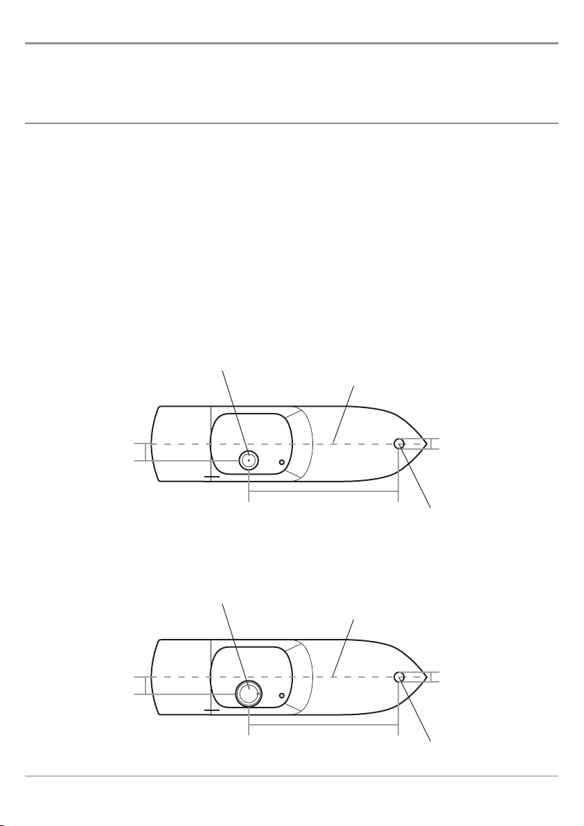
Shifting from the Center Line
Shift the scanner position from the center line to the starboard side of the boat to move shadow zones to
the port side. This makes it possible to keep a clear view to the bow. The distance to be shifted can be
calculated using the following equation:
Ls=0.4R+D/2 [m] (when R<15m)
Ls=0.025R+D/2 [m] (when R>=15m)
where: Ls = distance to be shifted from center line
D = diameter of obstacle on center line
R = distance from scanner to obstacle
Shifting from the Center Line (AS 12RD2KW)
Scanner Unit
Center Line
Installation
Shifting from the Center Line (AS 21RD4KW)
Scanner Unit
Center Line
6
Obstacle
Obstacle
Page 13

Obtaining Sufficient Dip Angle
Raise the scanner position so that there is a sufficient dip angle available between the line of sight from the
scanner to the obstacle and the horizontal line. By raising the dip angle 5°, it is possible to prevent mid- and
long-distance shadow zones. Don’t adjust the dip angle too high since the radar cannot detect objects below
the sight line.
Horizontal Line
Dip Angle
ight Line
S
Mounting Base
The scanner can be installed directly to a roof or other flat surface. You can also use a mounting bracket. Be
certain you keep the water drain tube clear. It is located at the bottom of the scanner unit.
NOTE: If the mounting bracket or surface has a curvature of more than 2 mm,use spacers with the mounting bolts to prevent
stress on the scanner housing.
Mounting
surface is
clear and doesn’t
trap water
Incorrect Mounting BaseCorrect Mounting Base
Do not mount on a
surface with an
edge that might trap
water.
7
Installation
Page 14

Installation
After you have chosen the mounting location, proceed to the installation section that matches your scanner
model.
AS 12RD2KW: Scanner Installation
Confirm that the mounting location meets the requirements described in the section Choose the
1.
Mounting Location.
2. Clean and dry the mounting surface.
3. Align the included template squarely with the center line of the boat (or chosen mounting
location), with the arrow pointing forward. Mark the four mounting holes.
NOTE: Check the template to confirm that the dimensions match the unit. Reproduction and moisture
can affect the size of the template.
4. Drill four 3/8 in. (10 mm) diameter holes through the mounting surface.
5. Check that each bolt (with lock washer andflat washer) protrudes through the mounting surface
at least 5/16 in. (8 mm) but less than 1/2 in. (13 mm).
CAUTION! The scanner will be damaged if bolts protrude more than 1/2 in. (13 mm).
6. Apply sealant around each mounting hole.
7. Place the scanner unit on the mounting surface. Orient the scanner with the index mark on the
housing facing forward (cable notch facing aft).
8. Install and tighten the four bolts as shown in the illustration Mounting the Scanner Unit.
9. Uncoil the scanner cable.
10. Secure the cable near the scanner to support the weight of the cable and prevent strain on the
watertight cable seal. If the cable is to pass through tubing or a bulkhead, protect the unfinished
end. Do not use the unfinished wires or fabric braid to pull the cable.
11. Route the cable to the operator’s location, securing it at appropriate points along the way. Make
a drip loop and apply sealant at the entry point of an exterior bulkhead. Proceed to Connect
Power.
Installation
8
Page 15

Scanner Orientation (AS 12RD2KW)
ndex Mark Facing Forward
I
Cable Notch Facing Aft
Mounting the Scanner Unit (AS 12RD2KW)
CAUTION! The scanner will be damaged if the bolts
protrude more than 1/2 in. (13 mm).
Index Mark
(faces forward)
Mounting Surface
(partial view)
Flat Washer
Lock Washer
Bolt
9
Installation
Page 16

AS 21RD4KW: Scanner Installation
1. Confirm that the mounting location meets the requirements described in the section Choose the
Mounting Location.
2. Clean and dry the mounting surface.
3. Align the included template squarely with the center line of the boat (or chosen mounting
location), with the arrow pointing forward. Mark the four mounting holes.
NOTE: Check the template to confirm that the dimensions match the unit. Reproduction and moisture can
affect the size of the template.
4. Drill four 1/2 in. (13 mm) diameter holes through the mounting surface.
5. Check that each bolt (with lock washer andflat washer) protrudes through the mounting surface
at least 5/16 in. (8 mm) but less than 1/2 in. (13 mm).
CAUTION! The scanner will be damaged if bolts protrude more than 1/2 in. (13 mm).
6. Apply sealant around each mounting hole.
7. Place the scanner unit on the mounting surface. Orient the scanner with the index mark on the
housing facing forward (cable notch facing aft).
8. Install and tighten the four bolts as shown in the illustration Mounting the Scanner Unit.
9. Uncoil the scanner cable.
10. Secure the cable near the scanner to support the weight of the cable and prevent strain on the
watertight cable seal. If the cable is to pass through tubing or a bulkhead, protect the unfinished
end. Do not use the unfinished wires or fabric braid to pull the cable.
11. Route the cable to the operator’s location, securing it at appropriate points along the way. Make
a drip loop and apply sealant at the entry point of an exterior bulkhead. Proceed to Connect
Power.
Installation
10
Page 17

Scanner Orientation (AS 21RD4KW)
ndex Mark Facing Forward
I
able Notch Facing Aft
C
Mounting the Scanner Unit (AS 21RD4KW)
CAUTION! The scanner will be damaged if the
bolts protrude more than 1/2 in. (13 mm).
11
Mounting Surface
(partial view)
Flat Washer
Lock Washer
Bolt
Installation
Page 18

Connect Power
Use the following instructions to connect power to the scanner unit. Also, see the illustration and table for
more information.
1. Route the cable to the fuse panel or battery (12V to 20 VDC required). Make sure that the Data
connector can also reach the control head.
2. Connect the Large Black wire to the negative (-) terminal of the fuse panel or battery.
3. Connect the Large White wire (with the in-line fuse) to the positive (+) terminal of the fuse panel
or battery.
NOTE: Do not remove the in-line fuse unless a dedicated and fused terminal is available. If so, install a 5A
fuse (AS 12RD2KW) or an 8 Amp fuse (AS 21RD4KW).
4. The green and blue wires must connect to enable radar (open = disabled, closed = enabled).
The installation options are as follows:
To connect the scanner to an On/Off switch or relay: Connect the small green wire to the
normally closed lead and the small blue wire to the normally open lead.
If you are not connecting the scanner to an On/Off switch or relay, connect the wires
together.
NOTE: The On/Off Switch or relay is optional. Please contact our Customer Resource Center for more
information.
NOTE: The On/Off control switch or relay provides a signal that controls the DC power inside the scanner
unit. It does not switch the main power leads to the scanner unit.
5. Plug the Data Connector into the adapter cable.
6. Connect the adapter cable to the control head's Ethernet port. Hand-tighten the screw nut.
7. Proceed to Radar Configuration.
Installation
12
Page 19

Function Wire Color Notes
1
Battery (+) Large White DC 12V to DC 20V
2
Battery (-) Large Black 0 Volts (ground)
3
*Switch, relay,
Small Green Normally Closed Lead
4
or terminated
Small Blue Normally Open Lead
5
Data -
}
Enable/Disable
Connects to the adapter cable, which connects to the
control head Ethernet Port.
Power Connection (AS 12RD2KW)
Power Connection (AS 21RD4KW)
1
2
3
4
5
1
2
3
4
5
*The On/Off Switch or relay isoptional. Please contact our Customer ResourceCenter for more information. The green and
blue wires must connect to enable radar (open = disabled, closed = enabled).
13
Installation
Page 20

Ethernet Port
800/900 Series™ (rear view)
1100 Series™ (rear view)
Installation
Ethernet Port
14
Page 21

Start/Stop Radar Transmission
Use the instructions in this section to start transmission or start a timed transmission.
WARNING! The radar must be configured before it can be used for complete on-the-water
operations. Start Transmission and proceed to Radar Configuration.
Start Transmission or Start Timed Transmission
1. Power On: Turn on the radar power source (breaker or switch). The radar will warm up for
60 to 90 seconds. The control head displays “Radar Ready” when it is safe to start transmission.
2. Press the VIEW key until the Radar View is displayed.
3. Press the MENU key.
4. Select Start Transmission from the X-Press™ Menu. Radar Transmission will start immediately.
OR
Select Start Timed Transmission. See Set Timed Transmission Settings to set up this
transmission mode in advance.
Set Timed Transmission Settings
Use Timed Transmission to set timed radar scans. This setting helps save power.
1. Press the VIEW key until the Radar View is displayed on the screen.
2. Press the MENU key twice.
3. Press the RIGHT Cursor key until the Accessories tab is selected.
4. Press the DOWN Cursor key to choose Radar, and press the RIGHT Cursor key to open the
submenu.
5. Use the 4-WAY Cursor Control key to select and adjust the following menu options:
Transmission Time: Sets the amount of time that the radar will transmit during
Timed Transmission mode. (0 - 60 seconds; Default = 30)
Standby Time: Sets the amount of time that the radar will pause between transmissions in
Timed Transmission mode. (0 - 60 seconds; Default = 30)
6. Close: Press the EXIT key.
Stop Transmission
1. With a Radar View displayed on the screen, press the MENU key.
2. Select Stop Radar Transmission. Radar Transmission will stop.
3. Power Off: Turn off the power source from the breaker or switch.
NOTE: You can also access the Stop Radar Transmission menu option from the Accessories Main Menu tab.
15
Start/Stop Transmission
Page 22

Radar Configuration (installation and repair only)
It is important to configure the radar with the control head after installation or equipment repair. The settings
in this section should only be needed periodically.
CAUTION! Installation and radar tuning should only be performed by a qualified radar service technician.
NOTE: To review the installation settings while the radaris transmitting,see Start/StopRadarTransmissionand startthe radar
transmission.
Open the Radar Installation Menu
1. Press the VIEW key until the Radar View is displayed on
the screen.
2. Press the MENU key twice.
3. Press the RIGHT Cursor key until the Accessories tab is
selected.
4. Press the DOWN Cursor key to choose Radar, and press
the RIGHT Cursor key to open the submenu.
5. Press the DOWN Cursor key to choose Installation, and
press the RIGHT Cursor key to select it.
Radar Installation Menu
Configuration
16
Page 23

Tune the Radar
The radar can be tuned automatically (Auto Tune) or manually (Manual Tune). Tuning is used to optimize the
radar system settings.
NOTE: For best results, run the tuning while there are targets within range, so it will be easier to review the data and make
djustments.
a
CAUTION! Do NOTinterrupt the power or press any keys on the control head while it is tuning.
1. Select Tune from the Installation menu.
2. Select Auto Tune or Manual Tune:
Auto Tune: Press the RIGHT Cursor key to start Auto Tune. Follow the on-screen instructions as
the control head stops radar transmission and starts automatic radar tuning.
OR
Manual Tune: Press the RIGHT Cursor key to open the Manual Tune submenu. Use the 4-WAY
Cursor Control key to select and adjust the following settings:
• Fine (0 - 255; Default = 50)
• Coarse (0 - 255; Default = 50)
3. Auto Tune Complete: The screen displays a dialog box to start radar transmission. Follow the
on-screen prompts. Press theRIGHT Cursor key to select Yes or press the LEFT Cursor key to select
No. It is not required to start radar transmission when the tuning is completed.
If the radar was tuned manually, press the EXIT key to return to the Installation menu.
Adjust the Trigger Delay
Trigger delay adjusts the signal timing so that long straight targets appear straight on the display.
NOTE: The following settings must be in place to optimize the Trigger Delay setting: Gain = 0, FTC = 0, STC = 0. See Adjust
Radar Settings for more information.
1. Select Trigger Delay from the Installation menu.
2. Use the 4-WAY Cursor Control key to select and adjust the following settings:
Gain: Press the RIGHT or LEFT Cursor keys to adjust the gain. The gain controls the amplification
of the radar signal. (0 - 255; Default = 0)
Trigger Delay: Press the RIGHT or LEFT Cursor keys to adjust the trigger delay. A high number sets
a longer delay, while a low number sets the radar to a shorter delay. (0 - 255; Default = 166)
3. Close: Press the EXIT key.
17
Configuration
Page 24

Set the Main Bang Suppression
Set the Main Bang Suppression to create a range around the boat, or the center of the Radar View, where
the radar signal will be suppressed. The targets in this range will not be seen.
1. Select Main Bang Suppression from the Installation menu.
2. Use the 4-WAY Cursor Control key to select and adjust the following settings:
STC: Press the RIGHT or LEFT Cursor keys to adjust the STC. STC filters the clutter that may
appear on the view during rough sea conditions. (0 - 255; Default = 50)
Gain: Press the RIGHT or LEFT Cursor keys to adjust the gain. The gain controls the amplification
of the radar signal. (0 - 255; Default = 0)
Main Bang Suppression: Press the RIGHT or LEFT Cursor keys to adjust the Main Bang
Suppression range. A high setting sets a wider radius around the radar and the boat, while a
low setting limits the radius to a shorter range. (0 - 255; Default = 221)
3. Close: Press the EXIT key.
CAUTION: As the Sector Blanking Range and Main BangSuppression are adjusted, it is important to note that targets within
these ranges are not displayed on the view.
Set the Sector Blanking Range
Sector Blanking sets an area where the radar will not transmit. This setting is useful for preventing
reflections or false echoes from displaying on the Radar View; however, any targets within this range are not
displayed on the view.
1. Select Sector Blanking from the Installation Menu.
2. Set Range: A line showing the first range of the sector will display on the view. Press the RIGHT
or LEFT Cursor keys to adjust the range.
3. Press the ENTER/INFO key to set the first range.
4. A second line will appear on the view. Repeat steps 2 and 3 to adjust the second sector. The
range is highlighted in gray on the view.
Delete Sector Blanking Range: Select Clear Blank Sector from the Installation Menu.
CAUTION: As the SectorBlanking Range and Main Bang Suppression are adjusted, it is important to note that targetswithin
these ranges are not displayed on the view.
Configuration
18
Page 25

ector Blanking: Press the RIGHT or LEFT Cursor keys to adjust the range.
S
Heading Line
A
1st Sector Blanking Range
B
2nd Sector Blanking Range
C
The range is highlighted in gray on the view.
D
Radar Installation Settings
A
B
D
C
Adjust the Heading Line
Use the Adjust Heading Line setting to synchronize the on-screen heading with the actual boat heading so
that north is displayed correctly on the view.
1. Select Adjust Heading Line from the Installation Menu.
2. Adjust Heading Angle: Press the RIGHT or LEFT Cursor keys, and a gray line will display on the
view.
3. Save: Press the ENTER/INFO key.
19
Configuration
Page 26

Radar Operations
After the radar is installed and configured by a qualified radar technician, it is ready for on-the-water
operation.
See Start/Stop Radar Transmission to start using your Humminbird® radar. We encourage
you to read this manual to understand the features of your Humminbird® radar and its available
menu settings.
Menus
The Radar Main Menu and the Radar X-Press™ Menu are used for radar operations such as display settings,
filter settings, and setting the EBL/VRM. For information about the Radar Installation menu, see Radar
Configuration.
Open the Radar Main Menu
1. Press the VIEW key until the Radar View is displayed on
the screen.
2. Press the MENU key twice.
3. Press the RIGHT Cursor key until the Accessories tab is
selected.
4. Press the DOWN Cursor key to choose Radar, and press
the RIGHT Cursor key to open the Radar Main Menu.
Operations
Radar Main Menu
20
Page 27

Radar X-Press™ Menu
Open the Radar X-Press™ Menu
1. Press the VIEW key until the Radar View is displayed on
the screen.
2. Press the MENU key once.
21
Operations
Page 28

Views
The radar scanner and GPS must be connectedto the control head to enable the radar operations functions
on your Humminbird® control head. When radar is connected, the Radar View and Chart/Radar Combo
View will be added to the view rotation. The available views will depend on your Humminbird® model.
Most of the menu settings in the following sections are enabled when a radar view is
displayed on the screen. Press the VIEW key until the Radar View or Chart/Radar Combo
View is displayed on the screen.
Radar View
The Radar View shows radar data on the full screen of your control head. See the following pages to
change the color palette, adjust sensitivity settings, and more.
What’s on the Radar View
A
Operations
E
G
Targets (multiple)
A
Range Ring
B
Bearing Ring
C
North Marker
D
B
D
Digital Readouts (see Select Readouts in your
C
F
Gain Setting
Radar Range Ring Setting
operations manual)
E
F
G
22
Page 29

Chart/Radar Combo View (GPS Required)
The Chart/Radar Combo View shows chart information and radar information in a combination split screen,
where the Chart View is displayed on the left, and the Radar View is displayed on the right.
Chart/Radar Combo View
A
B
C
Chart View
Green Arrow
Radar View
A
B
C
• Green Arrow and Active Side: The green arrow points to the active side. Press the MENU key
once and select Active Side from the X-Press™ Menu. Choose RIGHT or LEFT to set the active
side.
• X-Press™ Menu: After you set the Active Side, press the MENU key once to access the
X-Press™ Menu for the selected view. See Radar Display Settings for more information.
• Display Size: Press the MENU key once and select Split Position from the X-Press™ Menu. Split
Position allows you to adjust the size of the left side of the display. Press the RIGHT or LEFT
Cursor keys to adjust the display size.
• Active Cursor: Press any arrow on the 4-WAY Cursor Control key, and the cursor will appear on
the active side of the view.
23
Operations
Page 30

Radar Display Settings
Adjust Interference Rejection
Use the Interference Rejection setting to reduce the noise or interference from other transmitting radars in
the area.
1. Select Interference Rejection from the Radar Main Menu.
2. Press the RIGHT or LEFT Cursor keys to select the filter level. (Off, Low, Medium, or High;
Default = Off)
Change the Radar Display Palette
1. Select Radar Colors from the Radar Main Menu.
2. Press the RIGHT or LEFT Cursor keys to choose a color palette. The colors in each palette are
listed weakest return to strongest return, as follows:
Palette 1 = yellow to green
Palette 2 = dark green, bright green, yellow
Palette 3 = dark green to red (includes 8 shaded colors)
Display Range Rings
1. Select Range Rings from the Radar Main Menu.
2. Press the RIGHT or LEFT Cursor keys to select On or Off. (On= visible, Off = hidden; Default = On)
Radar View with Range Rings and Palette 2 Displayed
Operations
24
Page 31

Adjust Radar Settings
The settings in this section can be accessed from the Radar X-Press™ Menu. Use the settings in this section
to filter the returns on the display or increase the amount of returns on the display.
Adjust STC Settings
Use the STC menu option to control the clutter that may appear on the view during rough sea conditions.
1. With a Radar View displayed on the screen, press the MENU key.
2. Select STC from the X-Press™ Menu.
3. Press the RIGHT or LEFT Cursor keys to adjust the STC. (0 - 255; Default = 50)
Adjust Gain Settings
Use the Gain menu option to adjust the sensitivity of the radar. Increase the gain to see more targets on the
view, and decrease the gain to reduce the clutter caused by rain or snow.
1. With a Radar View displayed on the screen, press the MENU key.
2. Select Gain from the X-Press™ Menu.
3. Press the RIGHT or LEFT Cursor keys to adjust the Gain. (0 - 255; Default = 50)
Adjust FTC Settings
Use the Rain Clutter menu option to remove clutter that is caused by rain or snow.
1. With a Radar View displayed on the screen, press the MENU key.
2. Select FTC from the X-Press™ Menu.
3. Press the RIGHT or LEFT Cursor keys to adjust the FTC. (0 - 8; Default = 0)
Adjust the Transmission Range
The scanner transmission range can be adjusted from the X-Press™ Menu or by pressing the +/- ZOOM keys.
NOTE: The range setting affects all of the radar views in the control head. The control head will default to the largest chosen
area from all of the radar views.
1a. ZOOM Keys: Press the ZOOM (+) key to decrease the range (zoom in) or press the ZOOM (-) key
to increase the range (zoom out).
OR
1b. X-Press™ Menu: Press the MENU key. Select Range, and press the RIGHT or LEFT Cursor keys
to select a range setting. (.125 nm, .25 nm, .5 nm, .75 nm, 1 nm, 1.5 nm, 2 nm, 3 nm, 4 nm, 6 nm,
8 nm, 12 nm, 16 nm, 24 nm; AS 21RD4KW: includes 32 nm, 36 nm, 48 nm; Default = .25)
NOTE: To display the Range Rings, see Radar Display Settings.
25
Operations
Page 32

EBL/VRM
Use EBL (Electronic Bearing Range) and VRM (Variable Range Ring) to measure the distance and bearing
between any two targets on the Radar View.
The EBL and VRM can be set as a pair or individually. The marker is tied to the center of the boat. As the
boat’s position and heading moves, the EBL/VRM also moves. The control head allows you to create two sets
of EBL/VRM on the Radar View. You can choose to set the EBL/VRM with the cursor or by opening the
X-Press™ Menu.
Create an EBL/VRM with the Cursor (GPS required)
Setting the EBL/VRM with the cursor sets the ranges as a pair.
1. Use the 4-WAY Cursor Control key to move the active cursor to a position on the Radar View. The
first key press will activate the cursor.
2. Whenthe cursor is positionedover the chosen EBL/VRM intersection,press the ENTER/INFO key.
3. To set a second EBL/VRM, repeat steps 1 and 2.
Setting the EBL/VRM with the Cursor
D
B
A
Operations
A
Cursor
EBL
B
VRM
C
Cursor Dialog Box
D
C
E
F
G
H
EBL/VRM1 Digital Readout
Gain Setting
EBL/VRM2 Digital Readout
Radar Range Ring Setting
E
F
G
H
26
Page 33

Create an EBL/VRM with the X-Press™ Menu
Setting the EBL/VRM with the X-Press™ Menu allows you to set the EBL/VRM individually or as a pair.
1. Press the MENU key.
2. Select Create EBL/VRM1 or Create EBL/VRM2 (for the second set).
3. EBL: A dashed line will display on the Radar View. Press the RIGHT or LEFT Cursor keys to adjust
the EBL.
4. VRM: A dashed circle will display in the center of the Radar View. Press the UP or DOWN Cursor
keys to adjust the VRM.
NOTE: To adjust the VRM without the EBL, skip step 3. To adjust the EBL without the VRM, skip step 4.
5. Press the ENTER/INFO key to save your settings.
Setting the EBL/VRM with the X-Press™ Menu
A
F
Use the 4-WAY Cursor Control key
A
EBL2
B
C
VRM2
VRM1
D
D
B
C
E
G
EBL/VRM1 Digital Readout
EBL/VRM2 Digital Readout
EBL1
E
F
G
27
Operations
Page 34

EBL
Press the RIGHT or LEFT Cursor keys to adjust the EBL.
VRM
Press the UP or DOWN Cursor keys to adjust the VRM.
Save
Press the ENTER/INFO key to save your settings.
Edit an EBL/VRM Pair
An EBL/VRM must be saved to access this menu option.
1. Press the MENU key.
2. Choose Edit EBL/VRM from the X-Press™ Menu, and press the RIGHT Cursor key. If there is more
than one EBL/VRM, use the 4-WAY Cursor Control key to select 1 or 2 from the submenu.
3. EBL: Press the RIGHT or LEFT Cursor keys to adjust the EBL.
4. VRM: Press the UP or DOWN Cursor keys to adjust the VRM.
NOTE: To adjust the VRM without the EBL, skip step 3. To adjust the EBL without the VRM, skip step 4.
5. Press the ENTER/INFO key to save your settings.
Delete an EBL/VRM
An EBL/VRM must be saved to access this menu option.
1. Press the MENU key.
2. Choose Delete EBL/VRM from the X-Press™ Menu, and press the RIGHT Cursor key. If there is
more than one EBL/VRM, use the 4-WAY Cursor Control key to select 1 or 2 from the submenu.
Operations
28
Page 35

Specifications - AS 12RD2KW
Antenna Dimension . . . . . . . . . . . . . . . . . . . . . . . . . . . . . . . . . . . . . . . . . . . .0.9 ft (0.3 m), Enclosed Radome
Peak Power Output . . . . . . . . . . . . . . . . . . . . . . . . . . . . . . . . . . . . . . . . . . . . . . . . . . . . . . . . . . . . . . . . . . 2 kW
Transmit Frequency . . . . . . . . . . . . . . . . . . . . . . . . . . . . . . . . . . . . . . . . . . . . . . . . . . . . . . . . 9445 +/- 30 MHz
Beamwidth Horizontal . . . . . . . . . . . . . . . . . . . . . . . . . . . . . . . . . . . . . . . . . . . . . . . . . . . . . . . . . . . . . . . . . . 7°
Beamwidth Vertical . . . . . . . . . . . . . . . . . . . . . . . . . . . . . . . . . . . . . . . . . . . . . . . . . . . . . . . . . . . . . . . . . . . 25°
Sidelobes . . . . . . . . . . . . . . . . . . . . . . . . . . . . . . . . . . . . . . . . . . . . . . . . . . . . . . . . . . . . . . . . Better than -20dB
Rotation . . . . . . . . . . . . . . . . . . . . . . . . . . . . . . . . . . . . . . . . . . . . . . . . . . . . . . . . . . . . . . . . . . . . . . . . . . 30 rpm
Pulse Length
Short . . . . . . . . . . . . . . . . . . . . . . . . . . . . . . . . . . . . . . . . . . . . . . . . . . . . . . . . . . . . . . . . 0.1 uSec/2200/Hz
Medium 1 . . . . . . . . . . . . . . . . . . . . . . . . . . . . . . . . . . . . . . . . . . . . . . . . . . . . . . . . . . . . 0.3 uSec/1100/Hz
Long . . . . . . . . . . . . . . . . . . . . . . . . . . . . . . . . . . . . . . . . . . . . . . . . . . . . . . . . . . . . . . . . . 0.8 uSec/550/Hz
IF Center Frequency . . . . . . . . . . . . . . . . . . . . . . . . . . . . . . . . . . . . . . . . . . . . . . . . . . . . . . . . . . . . . . . . 60 MHz
IF Bandwidth
Short and Medium . . . . . . . . . . . . . . . . . . . . . . . . . . . . . . . . . . . . . . . . . . . . . . . . . . . . . . . . . . . . . . 6 MHz
Long . . . . . . . . . . . . . . . . . . . . . . . . . . . . . . . . . . . . . . . . . . . . . . . . . . . . . . . . . . . . . . . . . . . . . . . . . 3 MHz
Noise Figure . . . . . . . . . . . . . . . . . . . . . . . . . . . . . . . . . . . . . . . . . . . . . . . . . . . . . . . . . . . . . . . . . 10 dB or Less
Operating Temperature . . . . . . . . . . . . . . . . . . . . . . . . . . . . . . . . . . . . . . . . . . . . .-13 to 131° F (-25 to + 55C°)
Wind Force . . . . . . . . . . . . . . . . . . . . . . . . . . . . . . . . . . . . . . . . . . . . . . . . . . . . . . . . . . . . . . 100 Knots Relative
Water Resistance . . . . . . . . . . . . . . . . . . . . . . . . . . . . . . . . . . . . . . . . . . . . . . . . . . . . . . . . . . . . .IPX6 (IEC 529)
Voltage Supply . . . . . . . . . . . . . . . . . . . . . . . . . . . . . . . . . . . . . . . . . . . . . . . . . . . . . . . . . . . . . 10.8 to 31.2 VDC
Power Consumption . . . . . . . . . . . . . . . . . . . . . . . . . . . . . . . . . . . . . . . . . . . . . . . . . . . . . . . . . . . 30 W or less
Preheat time . . . . . . . . . . . . . . . . . . . . . . . . . . . . . . . . . . . . . . . . . . . . . . . . . . . . . . . . . . . . . . . . . . . 90 seconds
Cable Length . . . . . . . . . . . . . . . . . . . . . . . . . . . . . . . . . . . . . . . . . . . . . . . . . . . . . . . . . . . . . . . . . 33 feet (10 m)
NOTE: Product specifications and features are subject to change without notice.
29
Specifications
Page 36

Specifications - AS 21RD4KW
Antenna Dimension . . . . . . . . . . . . . . . . . . . . . . . . . . . . . . . . . . . . . . . . . . . . . 1.8 ft (.5 m) Enclosed Radome
Peak Power Output . . . . . . . . . . . . . . . . . . . . . . . . . . . . . . . . . . . . . . . . . . . . . . . . . . . . . . . . . . . . . . . . . . 4 kW
Transmit Frequency . . . . . . . . . . . . . . . . . . . . . . . . . . . . . . . . . . . . . . . . . . . . . . . . . . . . . . . . 9410 +/- 30 MHz
Beamwidth Horizontal . . . . . . . . . . . . . . . . . . . . . . . . . . . . . . . . . . . . . . . . . . . . . . . . . . . . . . . . . . . . . . . . . . 4°
Beamwidth Vertical . . . . . . . . . . . . . . . . . . . . . . . . . . . . . . . . . . . . . . . . . . . . . . . . . . . . . . . . . . . . . . . . . . . 25°
Sidelobes . . . . . . . . . . . . . . . . . . . . . . . . . . . . . . . . . . . . . . . . . . . . . . . . . . . . . . . . . . . . . . . . Better than -20dB
Rotation . . . . . . . . . . . . . . . . . . . . . . . . . . . . . . . . . . . . . . . . . . . . . . . . . . . . . . . . . . . . . . . . . . . . . . . . . . 24 rpm
Pulse Length
Short . . . . . . . . . . . . . . . . . . . . . . . . . . . . . . . . . . . . . . . . . . . . . . . . . . . . . . . . . . . . . . . . 0.1 uSec/2000/Hz
Medium 1 . . . . . . . . . . . . . . . . . . . . . . . . . . . . . . . . . . . . . . . . . . . . . . . . . . . . . . . . . . . 0.25 uSec/2000/Hz
Medium 2 . . . . . . . . . . . . . . . . . . . . . . . . . . . . . . . . . . . . . . . . . . . . . . . . . . . . . . . . . . . . 0.5 uSec/1000/Hz
Long . . . . . . . . . . . . . . . . . . . . . . . . . . . . . . . . . . . . . . . . . . . . . . . . . . . . . . . . . . . . . . . . . 1.0 uSec/500/Hz
IF Center Frequency . . . . . . . . . . . . . . . . . . . . . . . . . . . . . . . . . . . . . . . . . . . . . . . . . . . . . . . . . . . . . . . . 60 MHz
IF Bandwidth
Short and Medium . . . . . . . . . . . . . . . . . . . . . . . . . . . . . . . . . . . . . . . . . . . . . . . . . . . . . . . . . . . . . . 6 MHz
Medium 2 and Long . . . . . . . . . . . . . . . . . . . . . . . . . . . . . . . . . . . . . . . . . . . . . . . . . . . . . . . . . . . . 3 MHz
Noise Figure . . . . . . . . . . . . . . . . . . . . . . . . . . . . . . . . . . . . . . . . . . . . . . . . . . . . . . . . . . . . . . . . . 6.0 dB or Less
Operating Temperature . . . . . . . . . . . . . . . . . . . . . . . . . . . . . . . . . . . . . . . . . . . . . -13 to 131° F (-25 to + 55C°)
Wind Force . . . . . . . . . . . . . . . . . . . . . . . . . . . . . . . . . . . . . . . . . . . . . . . . . . . . . . . . . . . . . . 100 Knots Relative
Water Resistance . . . . . . . . . . . . . . . . . . . . . . . . . . . . . . . . . . . . . . . . . . . . . . . . . . . . . . . . . . . . IPX6 (IEC 529)
Voltage Supply . . . . . . . . . . . . . . . . . . . . . . . . . . . . . . . . . . . . . . . . . . . . . . . . . . . . . . . . . . . . . 10.8 to 41.6 VDC
Power Consumption . . . . . . . . . . . . . . . . . . . . . . . . . . . . . . . . . . . . . . . . . . . . . . . . . . . . . . . . . . . . 45W or less
Preheat time . . . . . . . . . . . . . . . . . . . . . . . . . . . . . . . . . . . . . . . . . . . . . . . . . . . . . . . . . . . . . . . . . . 120 seconds
Cable Length . . . . . . . . . . . . . . . . . . . . . . . . . . . . . . . . . . . . . . . . . . . . . . . . . . . . . . . . . . . . . . . . .33 feet (10 m)
NOTE: Product specificationsand features are subject to change without notice.
Specifications
30
Page 37

Contact Humminbird®
Contact the Humminbird® Customer Resource Center
in any of the following ways:
By Telephone:
(Monday - Friday 8:00 a.m. to 4:30 p.m. Central Standard Time):
1-800-633-1468
By e-mail:
(typically we respond to your e-mail within three business days):
service@humminbird.com
For direct shipping, our address is:
Humminbird
Service Department
678 Humminbird Lane
Eufaula, AL 36027 USA
31
 Loading...