

Humminbird 997c SI Combo Installation And Operation Manual

Thank You!
Thank you for choosing Humminbird®, America's #1 name in fishfinders. Humminbird® has built its reputation by designing and manufacturing top-quality,
thoroughly reliable marine equipment. Your Humminbird® is designed for trouble-free use in even the harshest marine environment. In the unlikely event that
your Humminbird® does require repairs, we offer an exclusive Service Policy - free of charge during the first year after purchase, and available at a reasonable
rate after the one-year period. For complete details, see the Warranty section in this manual. We encourage you to read this installation and operations manual
carefully in order to get full benefit from all the features and applications of your Humminbird® product.
Contact our Customer Resource Center at either 1-800-633-1468 or visit our website at www.humminbird.com.
WARNING! This device should not be used as a navigational aid to prevent collision, grounding, boat damage, or personal injury. When the boat is moving, water depth may change too quickly to allow time for you to react. Always operate the boat at very slow speeds if you suspect shallow water or submerged objects.
WARNING! Disassembly and repair of this electronic unit should only be performed by authorized service personnel. Any modification of the serial number or attempt to repair
the original equipment or accessories by unauthorized individuals will void the warranty.
WARNING! This product contains chemicals known to the State of California to cause cancer and/or reproductive harm.
NOTE: Some features discussed in this manual require a separate purchase, and some features are only available on international models. Every effort has been made to clearly
identify those features. Please read the manual carefully in order to understand the full capabilities of your model.
900 Series™, Cannon™, CannonLink™, DualBeam PLUS™, Fish ID+™, HumminbirdPC™, Humminbird®, InterLink™, One-Touch® Zoom, QuadraBeam PLUS™, RTS® Window, SmartCast®, Structure ID®, Total Screen
Update®, TrueArch®, WeatherSense®, WhiteLine®, WideSide®, X-Press™, and X-Press™ Menu are trademarked by or registered trademarks of Humminbird®.
© 2008 Humminbird®, Eufaula AL, USA. All rights reserved.
i

Table of Contents
900 Series™ Introduction 1
How the 900 Series™ Works ................................................................................................ 1
High Definition Side Imaging Sonar ...................................................................................... 2
DualBeam PLUS™ Sonar ...................................................................................................... 3
QuadraBeam PLUS™ Sonar
Universal Sonar 2 .................................................................................................................... 4
How GPS and Cartography Work .......................................................................................... 4
Multi-Media Card (MMC)/SD Slot ........................................................................................ 5
Software Updates .................................................................................................................... 5
Accessory Bus.......................................................................................................................... 6
(optional-purchase QuadraBeam PLUS™ transducer only)
.......... 3
Installation Overview 6
Control Head Installation 7
Gimbal Mounting the Control Head ...................................................................................... 7
Connecting the Control Head Power Cable to the Boat .................................................... 12
Transducer Installation 13
Transom Transducer Installation .......................................................................................... 14
Trolling Motor Transducer Installation ................................................................................ 19
Trolling Motor Transducer Options ...................................................................................... 19
Test and Finish the Transducer Installation ........................................................................ 20
GPS Receiver Installation 21
Stem Mounting with an Existing 1" - 14 Thread Stem ...................................................... 21
Access Under Mounting Location........................................................................................ 22
No Access Under Mounting Location.................................................................................. 23
Finish Routing the Cable and Check GPS Receiver Operation .......................................... 23
Testing the System Installation 24
Getting Started - Using Your 900 Series™ 25
Powering Up the Control Head ............................................................................................ 25
What’s on the Sonar Display .............................................................................................. 26
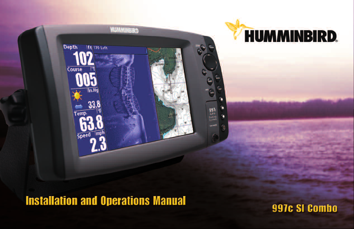
Understanding Sonar History .............................................................................................. 27
Real Time Sonar (RTS®) Window.......................................................................................... 27
Sonar Bottom Presentation .................................................................................................. 28
Understanding Side Imaging 29
What’s on the Side Imaging Display.................................................................................... 30
Side Imaging Technology: How It Works ............................................................................ 31
Side Imaging: On the Water Interpretation ........................................................................ 31
Key Functions 34
POWER/LIGHT Key ................................................................................................................ 34
VIEW Key................................................................................................................................ 35
MENU Key .............................................................................................................................. 35
4-WAY Cursor Control Key .................................................................................................... 36
View Preset Keys.................................................................................................................... 36
EXIT Key.................................................................................................................................. 36
INFO Key ................................................................................................................................ 37
MARK Key .............................................................................................................................. 37
GOTO Key................................................................................................................................ 37
ZOOM (+/-) Keys.................................................................................................................... 38
ii
531559-1_F

Table of Contents
Views 38
Views and Readouts.............................................................................................................. 39
Side Imaging View ................................................................................................................ 39
Sonar View ............................................................................................................................ 40
Sonar Zoom View .................................................................................................................. 41
Split Sonar View .................................................................................................................... 42
Side/Sonar Combo View ...................................................................................................... 43
Snapshot and Recording View ............................................................................................ 43
Side Beam View
Bird’s Eye View ...................................................................................................................... 50
Chart/Bird’s Eye Combo View .............................................................................................. 51
Chart/Chart Combo View ...................................................................................................... 52
Chart View.............................................................................................................................. 53
Chart/Sonar Combo View...................................................................................................... 54
Chart/Side Combo View........................................................................................................ 55
Chart Orientation .................................................................................................................. 56
(with optional-purchase QuadraBeam PLUS™ transducer only)
................ 48
Viewing Cartography 56
Navigation 57
Waypoints, Routes and Tracks.............................................................................................. 58
Save, Edit, or Delete a Waypoint.......................................................................................... 59
Navigate to a Waypoint or Position .................................................................................... 60
Add a Waypoint Target or Trolling Grid................................................................................ 60
Save, Edit or Delete a Route ................................................................................................ 61
Save or Clear a Current Track .............................................................................................. 62
Edit, Delete or Hide Saved Tracks ........................................................................................ 62
Man Overboard (MOB) Navigation ...................................................................................... 63
The Menu System 64
Start-Up Options Menu 65
Normal Operation .................................................................................................................. 66
Simulator .............................................................................................................................. 66
System Status ...................................................................................................................... 66
Self Test.................................................................................................................................. 67
Accessory Test........................................................................................................................ 67
GPS Diagnostic View ............................................................................................................ 68
Sonar X-Press™ Menu 69
Active Side.............................................................................................................................. 69
Split Position .......................................................................................................................... 70
Sensitivity .............................................................................................................................. 70
Upper Range
Lower Range.......................................................................................................................... 71
Chart Speed............................................................................................................................ 72
Quad Layout
(with optional-purchase QuadraBeam PLUS™ Transducer, Side Beam View only)
Bottom Lock
Bottom Range
Sonar Colors .......................................................................................................................... 73
Cancel Navigation
(Advanced: Sonar, Split Sonar and Active Sonar Side Views only)
(Sonar Zoom View only)
(Sonar Zoom View only, when Bottom Lock is on)
(only when navigating)
.................................................................................. 73
...................................... 73
.......................................................................... 73
................ 71
.......... 72
iii

Table of Contents
Side Imaging X-Press™ Menu 74
Active Side.............................................................................................................................. 74
Split Position .......................................................................................................................... 74
SI Side .................................................................................................................................... 75
SI Sensitivity .......................................................................................................................... 75
SI Range ................................................................................................................................ 75
Chart Speed............................................................................................................................ 75
SI Colors.................................................................................................................................. 76
Navigation X-Press™ Menu 76
Active Side.............................................................................................................................. 77
Split Position .......................................................................................................................... 77
Waypoint [Name]
Cursor to Waypoint
Save Current Track ................................................................................................................ 78
Clear Current Track................................................................................................................ 78
Save Current Route
Skip Next Waypoint
Cancel Navigation
Cancel MOB Navigation
Remove Target
Remove Grid
Waypoint Name
(only with an active cursor on a waypoint)
(Chart or Combo view only)
(only when navigating)
(only when navigating)
(only when navigating)
(only when MOB Navigation is activated)
(only if a Target is active)
(only if a Grid is active)
(most recently-created waypoint)
.......................................................................... 79
........................................................................ 79
............................................................................ 79
.............................................................................. 80
...................................................................................... 80
.............................................. 77
.................................................................. 78
.................................... 79
.............................................................. 80
Snapshot and Recording X-Press™ Menu
(Snapshot and Recording View only) 81
Start Recording
(optional-purchase MMC/SD Card, Snapshot and Recording View only) ..........................
Stop Recording
(optional-purchase MMC/SD Card only) ......................................................
Delete Image
(optional-purchase MMC/SD Card, Snapshot and Recording View only) ..........................
Delete All Images
(optional-purchase MMC/SD Card, Snapshot and Recording View only) ..........................
Delete Recording
(optional-purchase MMC/SD Card, Snapshot and Recording View only) ..........................
Delete All Recordings
(optional-purchase MMC/SD Card, Snapshot and Recording View only) ..........................
Pings Per Second
(optional-purchase MMC/SD Card, Snapshot and Recording View only) ..........................
Playback Speed
(optional-purchase MMC/SD Card, Snapshot and Recording View only) ..........................
Stop Playback
(optional-purchase MMC/SD Card only) ........................................................
Sonar Menu Tab 85
Beam Select .......................................................................................................................... 86
Side View Frequency
(Side Views only)
Fish ID+™ .............................................................................................................................. 87
Fish ID Sensitivity .................................................................................................................. 88
Real Time Sonar (RTS®) Window.......................................................................................... 88
Bottom View .......................................................................................................................... 89
Zoom Width
(Sonar Zoom View only)
83 kHz Sensitivity .................................................................................................................. 89
................................................................................ 86
.................................................................................... 89
82
82
82
83
83
84
84
84
85
iv

Table of Contents
455 kHz Sensitivity
Depth Lines
Surface Clutter
Noise Filter
Max Depth
Water Type
(Advanced, with optional-purchase QuadraBeam PLUS™ transduceronly)
(Advanced)
(Advanced)
(Advanced)
(Advanced)
........................................................................................................ 90
(Advanced)
.................................................................................................... 91
.......................................................................................................... 91
.......................................................................................................... 92
.......................................................................................................... 92
...... 89
Transducer Select .................................................................................................................. 93
Color Bar ................................................................................................................................ 93
Temperature Graph
(Sonar View only, with Temperature input)
.......................................... 93
Navigation Menu Tab 94
Current Track.......................................................................................................................... 94
Saved Tracks .......................................................................................................................... 95
Waypoints .............................................................................................................................. 95
Routes .................................................................................................................................... 96
Chart Orientation .................................................................................................................. 96
North Reference .................................................................................................................... 97
Trolling Grid Rotation ............................................................................................................ 97
Trackpoint Interval ................................................................................................................ 97
Track Min Distance
(Advanced)
Track Color Range.................................................................................................................. 98
Map Datum
(Advanced)
Course Projection Line .......................................................................................................... 99
Export All Nav Data
Delete All Nav Data
(Advanced)
(Advanced)
Continuous Navigation Mode .............................................................................................. 99
............................................................................................ 98
........................................................................................................ 98
............................................................................................ 99
............................................................................................ 99
Chart Menu Tab 100
Chart Detail Level ................................................................................................................ 100
Map Borders ........................................................................................................................ 101
Lat/Lon Grid.......................................................................................................................... 101
Spot Soundings.................................................................................................................... 101
Navaids on Bird's Eye View..................................................................................................102
Shaded Depth...................................................................................................................... 102
Set Simulation Position
Set Map Offset
Clear Map Offset
(Advanced)
(Advanced)
(Advanced)
.................................................................................... 102
.................................................................................................. 103
.............................................................................................. 103
Alarms Menu Tab 104
Depth Alarm ........................................................................................................................ 104
Fish ID Alarm........................................................................................................................ 104
Low Battery Alarm .............................................................................................................. 105
Aux Temp Alarm
(with optional-purchase temp. probe or Temp/Speed only)
.................... 105
Temp Alarm .......................................................................................................................... 106
Off Course Alarm ................................................................................................................ 106
Arrival Alarm ........................................................................................................................ 107
Drift Alarm............................................................................................................................ 107
Alarm Tone .......................................................................................................................... 108
Setup Menu Tab 108
Units - Depth........................................................................................................................ 109
v
Units - Temp
(International only)
Units - Distance
(with Speed input only)
.......................................................................................... 109
............................................................................ 109

Table of Contents
Units - Speed
User Mode............................................................................................................................ 110
Language
Triplog Reset
Restore Defaults .................................................................................................................. 110
Select Readouts
Depth Offset
Aux. Temp. Offset
Temp Offset
Speed Calibration
Local Time Zone
Daylight Saving Time
Position Format
Time Format
Date Format
Digits Format
NMEA Output
Sonar .................................................................................................................................... 116
(with Speed input only)
(International only)
(with Speed input only)
(Advanced)
(Advanced)
(Advanced)
(Advanced, International only)
(Advanced, International only)
(Advanced)
...................................................................................................... 112
(Advanced)
...................................................................................................... 113
(Advanced, with Speed paddlewheel only)
(Advanced)
(Advanced)
(Advanced)
......................................................................................................115
(Advanced)
.................................................................................................. 115
................................................................................ 109
.............................................................................................. 110
.................................................................................. 110
................................................................................................ 111
.............................................................................................. 113
................................................................................................ 113
........................................................................................ 114
................................................................................................ 114
............................................ 113
........................................................................ 114
........................................................................ 114
Views Menu Tab 116
Accessories Menu Tab 118
Using Screen Snapshot ...................................................................................................... 118
Troubleshooting 120
900 Series™ Doesn’t Power Up.......................................................................................... 120
900 Series™ Defaults to Simulator with a Transducer Attached.................................... 120
Display Problems 121
Finding the Cause of Noise 122
1-Year Limited Warranty 123
Humminbird® Service Policy 123
900 Series™ Accessories 125
Specifications 127
Glossary 128
Appendix A - Transducer Mounting Template: XHS 9 HDSI 180 T 138
Contact Humminbird® 143
NOTE: Entries in this Table of Contents which list (International only) are only
available on products sold outside of the US and Canada by our authorized
International Distributors. It is important to note that products sold in the U.S. are
not intended for resale in the international market. To obtain a list of authorized
International Distributors, please visit our website at www.humminbird.com or
contact our Customer Resource Center at 1-800-633-1468 to locate the
distributor nearest you.
NOTE: Entries in this Table of Contents which list (with Speed Input) or (with
Temperature Input) may require the purchase of separate accessories. You can
visit our website at www.humminbird.com to order these accessories online or
contact our Customer Resource Center at 1-800-633-1468.
vi

900 Series™ Introduction
Your 900 Series™ Ultra Wide Screen Fishing System comes in the following
configuration:
• Humminbird® 997c Combo: Ultra Wide Screen Fishing System with
Chartplotter (Maps) and Side Imaging and Dual Frequency
Transducer, GPS Receiver included.
How Sonar Works
Sonar technology is based on sound waves. The 900 Series™ Fishing System
uses sonar to locate and define structure, bottom contour and composition,
as well as depth directly below the transducer.
Your 900 Series™ Fishing System sends a sound wave signal and determines
distance by measuring the time between the transmission of the sound
wave and when the sound wave is reflected off of an object; it then uses the
reflected signal to interpret location, size, and composition of an object.
Sonar is very fast. A sound wave can travel from the surface to a depth of
240 ft (70 m) and back again in less than 1/4 of a second. It is unlikely that
your boat can "outrun" this sonar signal.
SONAR is an acronym for SOund and
NAvigation Ranging. Sonar utilizes precision
sound pulses or "pings" which are emitted into
the water in a teardrop-shaped beam.
The sound pulses "echo" back from objects in
the water such as the bottom, fish and other
submerged objects. The returned echoes are
displayed on the LCD screen. Each time a new
echo is received, the old echoes are moved
across the LCD, creating a scrolling effect.
When all the echoes are viewed side by side,
an easy to interpret "graph" of the bottom, fish
and structure appears.
1
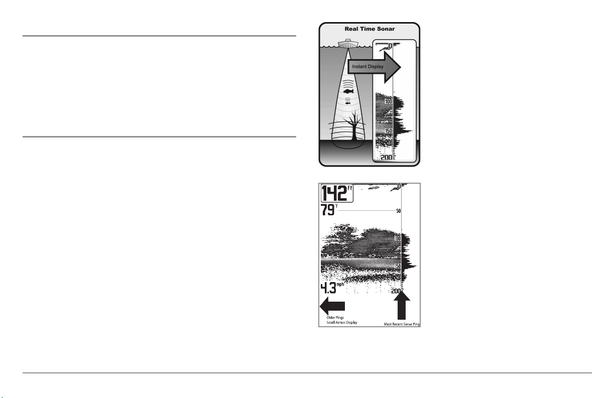
The sound pulses are transmitted at various
60°
8
3kHz
20°
200kHz
86°
4
55kHz
86°
4
55kHz
frequencies depending on the application.
Very high frequencies (455 kHz) are used for
greatest definition but the operating depth is
limited. High frequencies (200 kHz) are
commonly used on consumer sonar and
provide a good balance between depth
performance and resolution. Low frequencies
(83 kHz) are typically used to achieve greater
depth capability.
High Definition Side Imaging Sonar
Your 900 Series™ 997c SI Combo uses
Side Imaging sonar to provide a wide yet
precise survey of a large area of water,
including detailed bottom topography
and fish-attracting structure orientation.
The Side Imaging transducer returns are
processed into an image similar to an
aerial photograph. Typically, the Side
Imaging sonar can search an area that
is 720 feet wide (360 to each side), with
a typical depth performance of 150
The power output is the amount of energy
generated by the sonar transmitter. It is
commonly measured using two methods:
• Root Mean Square (RMS) measures power
output over the entire transmit cycle.
• Peak to Peak measures power output at the
highest points.
The benefits of increased power output are
the ability to detect smaller targets at greater
distances, ability to overcome noise, better
feet when the Side Imaging Sonar
frequency is set for 455kHz. The side
beams can be operated at one of two
frequencies: 455 kHz or 800 kHz.
Selecting 800 kHz produces the sharpest
image but the search area to each side
and the depth capability are limited as
compared to the 455 kHz frequency. See
What’s on the Side Imaging Display
and Understanding Side Imaging for
more information.
high speed performance and enhanced depth
capability.
2
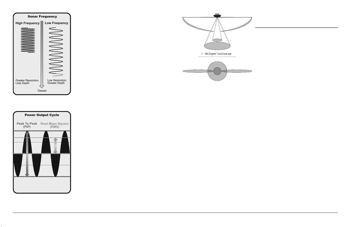
DualBeam PLUS™ Sonar
90° Total Coverage
Bottom Coverage=2 x Depth
35° 60° 20° 35°
455 kHz 455 kHz
83 kHz
200 kHz
Your 900 Series™ Fishing System uses a
200/83 kHz DualBeam PLUS™ sonar system
with a wide (60°) area of coverage.
DualBeam PLUS™ sonar has a narrowly
focused 20° center beam, surrounded by a
second beam of 60°, expanding your
coverage to an area equal to your depth. In
20 feet of water, the wider beam covers an
area 20 feet wide. The 20° center beam is
focused on the bottom, to show you
structure, weeds and cover. The 60° wide
beam is hunting for fish in the wide
coverage area. DualBeam PLUS™ sonar
returns can be blended together, viewed
separately or compared side-by-side.
DualBeam PLUS™ is ideal for a wide range
of conditions - from shallow to very deep
water in both fresh and salt water. Depth
capability is affected by such factors as boat
speed, wave action, bottom hardness, water
conditions and transducer installation.
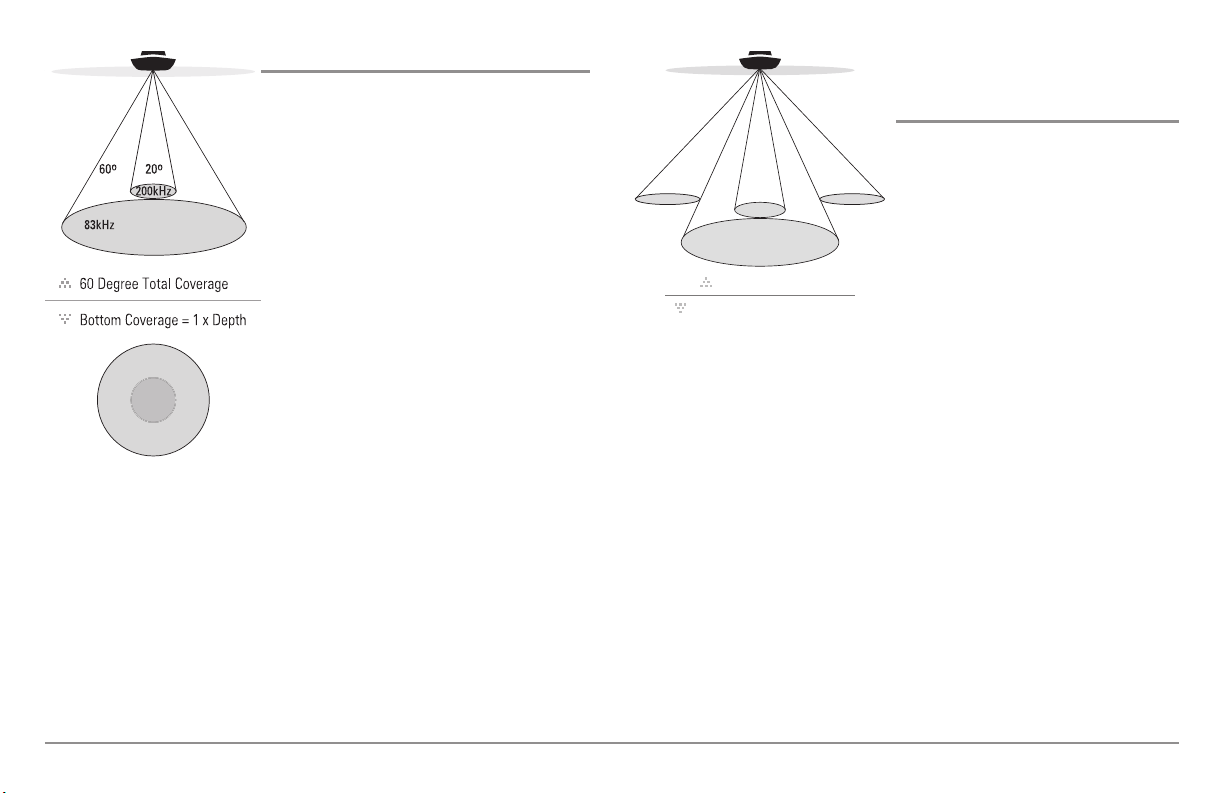
QuadraBeam PLUS™ Sonar
(optional-purchase QuadraBeam PLUS™
transducer only)
Your 900 Series™ 997c Combo supports
the optional-purchase QuadraBeam
PLUS™ transducer. QuadraBeam
PLUS™ sonar provides an extremely
wide (90°) area of coverage.
QuadraBeam PLUS™ starts with two
fan-shaped 35° 455 kHz Side Structure
locating sonar beams to spot fish, bait
and structure to the left and right of the
boat over an area of the bottom that’s
always equal to twice your depth.
For a detailed view below the boat, QuadraBeam PLUS™ uses DualBeam
PLUS™ technology, with precision 20° and wide 60° beams. QuadraBeam
PLUS™ finds more fish faster, and can even tell you where to put your bait
by showing if fish are to the left, right or directly beneath your boat.
3

Universal Sonar 2
Your 900 Series™ Fishing System supports Universal Sonar 2, a state-of-theart, integrated and protected transducer that is built into the lower unit of
Minnkota trolling motors. With Universal Sonar 2, all wiring is concealed
inside the indestructible composite shaft—out of sight and out of harm’s
way, with no clamps, ties, or exposed wires. Universal Sonar 2 features new
temperature sensing and the performance of DualBeam PLUS™ technology.
An expanded view and greater bottom detail gives you a totally new
perspective of the water below, along with optimal sonar performance to
help you find fish.
How GPS and Cartography Work
Your 900 Series™ Fishing System also supports GPS and chartplotting, and
uses GPS and sonar to determine your position, display it on a grid, and
provide detailed underwater information. The Global Positioning System
(GPS) is a satellite navigation system designed and maintained by the U.S.
Department of Defense. GPS was originally intended for military use;
however, civilians may also take advantage of its highly accurate position
capabilities, typically within +/- 4.5 meters, depending on conditions. This
means that 95% of the time, the GPS receiver will read a location within 4.5
meters of your actual position. Your GPS Receiver also uses information from
WAAS (the Wide Area Augmentation System), EGNOS (the European
Geostationary Navigation Overlay Service), and MSAS (the MTSAT Satellite
Augmentation System) satellites if they are available in your area.
GPS uses a constellation of over 24 satellites
that continually send radio signals to the earth.
Your present position is determined by
receiving signals from up to 16 satellites and
measuring the distance from the satellites.
All satellites broadcast a uniquely coded signal
once per second at exactly the same time. The
GPS receiver on your boat receives signals from
satellites that are visible to it. Based on time
differences between each received signal, the
GPS receiver determines its distance to each
satellite. With distances known, the GPS receiver
mathematically triangulates its own position.
With once per second updates, the GPS receiver
then calculates its velocity and bearing.
The GPS Receiver included with your 900 Series™ Fishing System allows you
to combine easy-to-use FishingGPS® chartplotter and navigation capabilities
with advanced fishfinding.
4

The following GPS functionality is currently supported by the 900 Series™
Fishing System when it is connected to the included GPS receiver:
Multi-Media Card
(MMC)/SD Slot
• View current position
• View current track (breadcrumb trail)
• View precision speed and heading from your GPS receiver
• Save tracks, waypoints and routes
• Travel a route and navigate from one waypoint to the next.
Your 900 Series™ supports Navionics® Gold, HotMaps™ and HotMaps™
Premium on MMC or SD card media.
NOTE: Your 900 Series™ does not support Navionics® Classic Charts, only
Navionics® Gold, HotMaps™, and HotMaps™ Premium.
Your unit also comes with a built-in UniMap™ with a more detailed map of
North America (Domestic models) or a more detailed map of Europe and
Southeast Asia, including Australia and New Zealand (International models).
Your 900 Series™ uses the GPS Receiver to determine the position of the
boat automatically, and uses the zoom level settings on a particular view to
select the best chart to display. See Viewing Cartography for more
information.
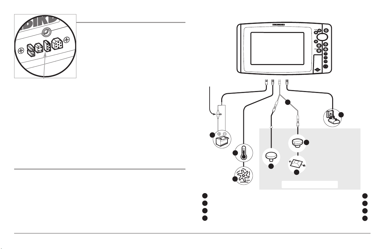
Your 900 Series™ Fishing System also has a
multi-media card (MMC)/SD slot that is used
to insert optional-purchase cards containing
additional detailed maps. If you insert an
MMC/SD that contains a more detailed
chart for a particular location, your 900
Inserting an MMC/SD
into the Card Slot
Series™ Fishing System will retrieve that
chart and display it automatically. Use the
illustration to locate the position of the MMC/SD slot cover, remove the
MMC/SD slot cover, then insert the MMC/SD into the slot. The label on the
MMC/SD should face toward the left side of the unit. Press down on the
card until it clicks into place and replace the slot cover. Then, replace and
tighten snugly - do NOT overtighten, as this will not improve water
resistance, and may damage the cover.
Software Updates
Use the MMC/SD slot to update the software version of your control head.
To update the software in your control head, plug in the appropriate
MMC/SD card that contains a software update file; the unit will recognize it,
will tell you what software version your control head is currently running,
and will ask you if you want to update the software in the unit to match that
on the MMC/SD card. You can obtain software updates from the
www.humminbird.com website.
5
Accessory Bus
Accessory Bus
Use the Accessory Bus to expand the
functionality of your 900 Series™. Accessories
plug directly into the 900 Series™, enabling
Advanced features such as WeatherSense®
and the SmartCast® Wireless Sonar Link.
Additional tabs and menu choices will be
added to the menu system automatically when
an accessory is plugged into the unit. In
addition, multiple accessories can be attached
simultaneously. See Accessories Menu Tab
and 900 Series™ Accessories in this manual,
as well as your accessory Operations Manual
for additional details.
The 900 Series™ has a wide variety of configurations.
2
1
NOTE: Accessories to enable WeatherSense® and the SmartCast® Wireless Sonar Link
require separate purchases. You can visit our website at www.humminbird.com or
contact our Customer Resource Center at 1-800-633-1468 for additional details.
Installation Overview
Please read all instructions that are relevant for your configuration before
beginning the installation process.
NOTE: Installation procedures will depend on product configuration.
3
Sonar Transducer w/Temperature
1
Optional “Y” Cable
2
Power
3
Temperature/Speed
4
5
6
8
4
6
5
7
Accessory Bus
SmartCast® Wireless Sonar Link
Speed through water
GPS Receiver
WeatherSense®
5
6
7
8
Inside the boat there is often a channel or conduit used for other wiring, this
can be used to route cables. Be sure to route the cable as far as practical
from the antenna cable of VHF radios or tachometer cables to reduce the
possibility of interference. The transducer and GPS receiver cables should
not be cut, and care should be used not to damage the cable insulation.
Basic installation tasks that you must perform include:
• Installing the control head (choosing either gimbal or in-dash
mounting, where in-dash mounting requires a separate purchase)
• Installing the transducer (choosing either the transom mount,
inside the hull mount, or trolling motor mounting method)
• Installing the GPS Receiver (if included)
• Testing the complete installation and locking the transducer position.
NOTE: Accessories may require a separate purchase. You can visit our website at
www.humminbird.com to order these accessories online or contact our
Customer Resource Center at 1-800-633-1468.
Control Head Installation
You have two choices for mounting your 900 Series™ control head, Gimbal
mounting, where you use a surface on the boat, such as the dash, to mount
the control head so that it can be tilted up or down, or In-dash mounting,
which requires a separate purchase.
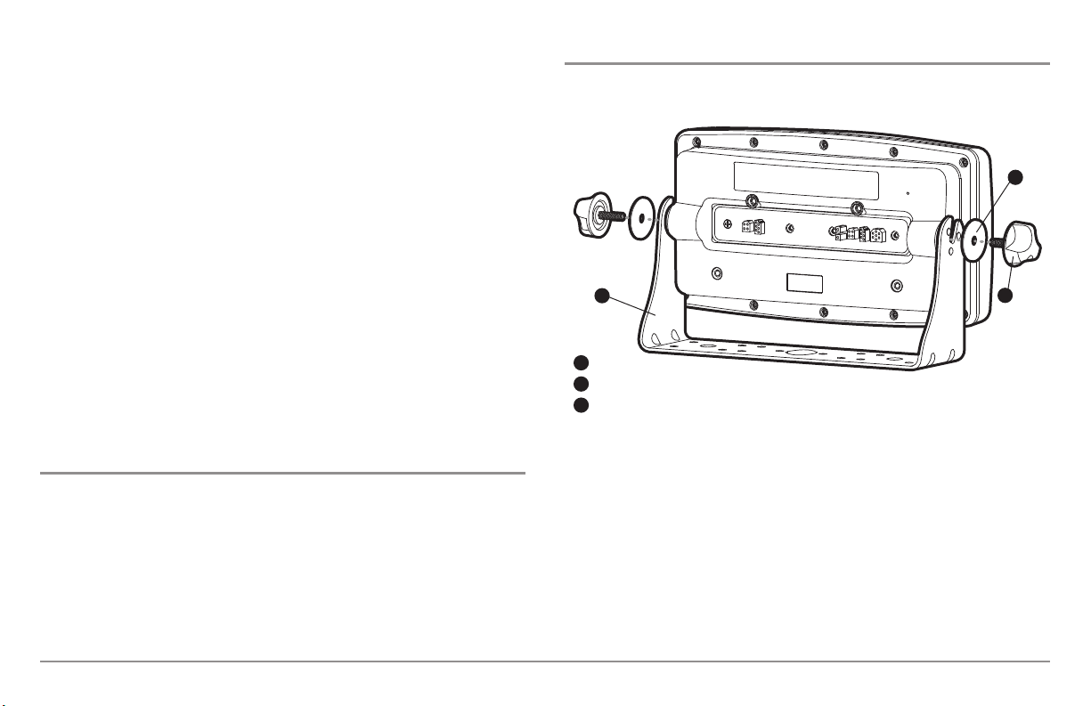
Gimbal Mounting the Control Head
If you are gimbal mounting the Humminbird® 900 Series™, you can preassemble the unit in order to plan the best mounting location.
1
3
Washer
1
Gimbal Knob
2
Gimbal Bracket
3
In addition to the hardware supplied with your control head, you will need
a powered hand drill and various drill bits, various hand tools, including a
Phillips head screwdriver, a socket wrench and a flat head screwdriver, a
marker or pencil, safety glasses and dust mask, and marine-grade silicone
sealant.
2
7

1. Place the control head into the gimbal bracket. Make sure that the
straight side of the gimbal arm is against the back side of the control
head.
2. Place a 1" (25 mm) diameter black washer on the gimbal knob and
then thread the knob and washer into the housing. Tighten the
gimbal knob to secure the 900 Series™ control head to the mount.
Repeat step 2 for the other side.
You can now place the control head in various locations to decide which is
best for mounting. Rotating the mounting bracket to the top of the control
head will allow for overhead mounting. The chosen mounting area should
allow for sufficient room so the control head can pivot through the full tilt
range and allow for easy removal and installation.
NOTE: You can drill the cable pass hole underneath the gimbal bracket, allowing
you to thread the cables through the knock-out holes in the mount; however, if
you cannot drill the hole directly under the mounting bracket, then you will need
to drill the cable pass hole behind the bracket, and will need to mount the hole
cover there instead.
NOTE: When drilling holes in fiberglass hulls, it is best to start with a smaller bit
and use progressively larger drill bits to reduce the chance of chipping or flaking
the outer coating. Fill all holes with marine grade silicone sealant.
NOTE: You must have underside access to the mounting location to pass the
cables through to the surface. Also, make sure that the mounting surface is
adequately supported to protect the control head from excessive wave shock and
vibration and provide visibility while in operation.
3. After the mounting location has been determined, loosen the gimbal
knobs and remove the control head from the gimbal bracket.
NOTE: Alternate hole patterns are available on the gimbal mounting bracket, and
may match existing holes on the boat. You may choose to use one of these
alternate hole patterns.
4. Place the gimbal bracket in the chosen position on the mounting
surface and mark the four mounting screw locations using a pencil
or center punch.
NOTE: Go to the installation instructions applicable to your transducer, GPS
Receiver and accessories. Make the required installations and then run the
cables to your control head mounting location. Do not cut any cabling (except the
power cable). If your cables are too short, extensions are available from your local
dealer or online from www.humminbird.com.
8
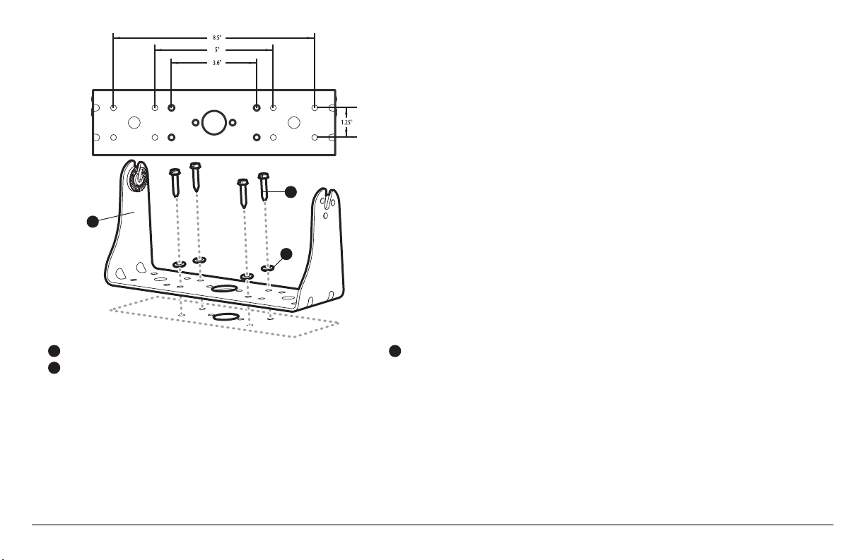
1
3
2
Mounting Screws
1
Washer
2
Gimbal Mounting Bracket
3
5. Set the gimbal bracket aside and drill the four mounting screw holes
using a 5/32" (4.0 mm) drill bit.
6a. If the cables must pass through a hole directly beneath the
mounting bracket, mark and drill an additional 1" (25 mm) hole
centered between the four mounting holes. Route the cables
through the 1" hole. Place the hole cover over the mounting surface
hole, then use it to mark the position of the two mounting screws.
Remove the hole cover, drill the two mounting holes using a 9/64"
bit. Do not install the hole cover at this time.
6b. If the cables cannot be routed directly beneath the mounting
bracket, mark and drill a 1" (25 mm) hole that will allow you to run
the cables close to the bracket. Pass the cables through the 1" (25
mm) hole, routing the cables through the grommet and pressing the
grommet into place. Place the hole cover over the mounting surface
hole, then use it to mark the position of the two mounting screws.
Remove the hole cover, drill the two mounting holes using a 9/64"
(3.5 mm) bit, fill them with marine-grade silicone, then replace the
hole cover and insert the #8 Phillips countersink wood screws.
Hand-tighten only.
7. Place the mounting bracket on the mounting surface aligned with
the drilled holes and fill the mounting holes with marine grade
silicone. Insert the four #10 Slotted-Hex wood screws into the
mounting holes. Hand-tighten only.
8. If the cable pass through hole is beneath the mounting bracket, you
will need to install the hole cover. Place the hole cover over the
mounting bracket cable pass thru hole and align with holes drilled
in step 6a. Insert the #8 Phillips countersink wood screws. Hand
tighten only.
NOTE: Be sure that the cables pass through the slots on the hole cover and that
there is enough cable slack to allow for the control head to pivot through its full tilt
range. Extra cable slack will also help when connecting/disconnecting the cables.
9
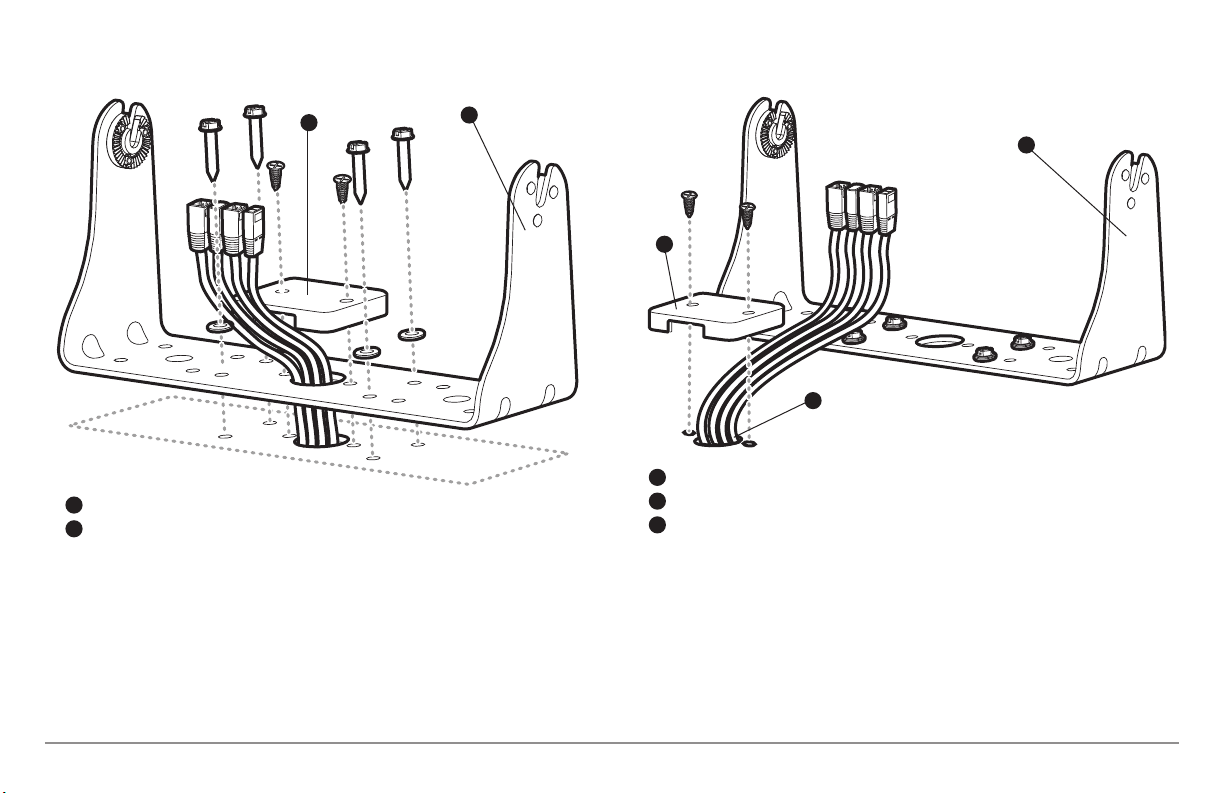
Cables Routed Directly Beneath Mounting Bracket
Cables Routed Behind Mounting Bracket
Gimbal Bracket
1
Hole Cover
2
2
1
1
3
2
Gimbal Bracket
1
Grommet
2
Hole Cover
3
9. Insert cable connectors into the proper recesses on the cable
collector insert. The cable connectors are keyed to prevent reverse
installation, so be careful not to force the connectors into the wrong
slots. If you don’t have a cable for every hole in the insert, install the
blank plugs to protect the control head from the weather.
10
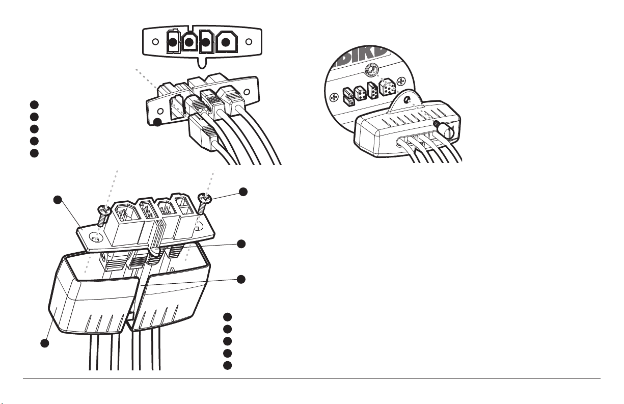
Power
1
Temp/Speed
2
Communications
3
Transducer
4
Cable Collector Insert
5
1
3
1 2
3 4
Plug Cable Connector Assembly to
Back of Control Head
10. While holding cables in place in
the cable collector insert, thread the
cables through the slot in the bottom
of the cable collector cover, line up
the cable collector insert and cover,
then slide the cover into place on the
insert.
5
NOTE: The tab on the Cable Collector
insert goes into the slot on the cover.
11. Attach the cable collector insert to the cable collector cover using
2
the 2 Phillips screws provided.
12. Place the control head back onto the mounting bracket. Plug in the
cable collector assembly to the back of the control head. Cable
connectors and cable sockets are keyed to prevent reverse
4
installation, so be careful not to force the connectors into the wrong
sockets. Once the cable collector and all cables are plugged into the
back of the control head, lock the assembly into place by threading
5
the knurled screw into the threaded insert on the back of the
housing. Adjust the control head to the desired viewing angle and
secure by tightening the gimbal knobs.
Cable Collector Insert
1
Screws
2
Cable Collector Cover
3
Tab on Insert
4
Slot on Cover
5
NOTE: You may wish to dress the cabling with nylon wire ties in order to hold the
cables together and create a cleaner assembly.
The Humminbird® 900 Series™ control head is now ready for operation.
11
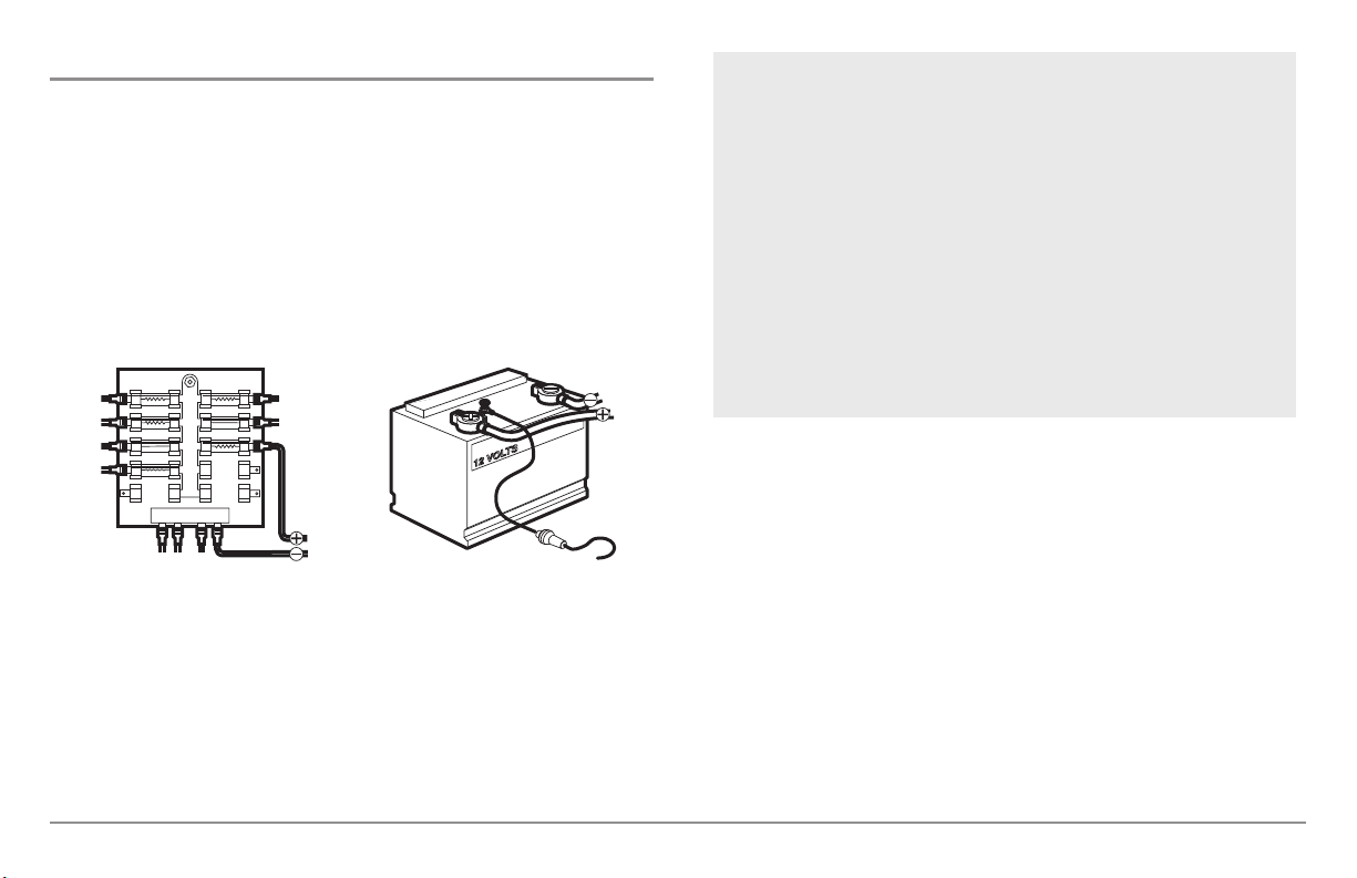
Connecting the Control Head Power Cable to the Boat
GROUNDGROUND
POSITIVEPOSITIVE
A 6' (2 m) long power cable is included to supply power to the control head.
You may shorten or lengthen the cable using 18 gauge multi-stranded
copper wire.
CAUTION: Some boats have 24 or 36 Volt electric systems, but the control head
MUST be connected to a 12 VDC power supply.
The control head power cable can be connected to the electrical system of
the boat at one of two places: a fuse panel usually located near the console,
or directly to the battery.
NOTE: Make sure that the power cable is disconnected from the control head at
the beginning of this procedure.
NOTE: Humminbird® is not responsible for over-voltage or over-current failures.
The control head must have adequate protection through the proper selection
and installation of a 3 amp fuse.
1a. If a fuse terminal is available, use crimp-on type electrical
connectors (not included) that match the terminal on the fuse
panel. Attach the black wire to ground (-), and the red wire to
positive (+) 12 VDC power. Install a 3 amp fuse (not included) for
protection of the unit. Humminbird® is not responsible for overvoltage of over-current failures.
or...
1b. If you need to wire the control head directly to a battery, obtain
and install an inline fuse holder and a 3 amp fuse (not included)
for the protection of the unit. Humminbird® is not responsible for
overvoltage or over-current failures.
NOTE: In order to minimize the potential for interference with other marine
electronics, a separate power source (such as a second battery) may be
necessary.
You are now ready to install the transducer. Find the section that refers to
your specific transducer installation method.
12
Transducer Installation
There are two different installation methods for your transducer:
• Transom Transducer
• Trolling Motor Transducer.
Find the section that describes the method of installation you will be using.
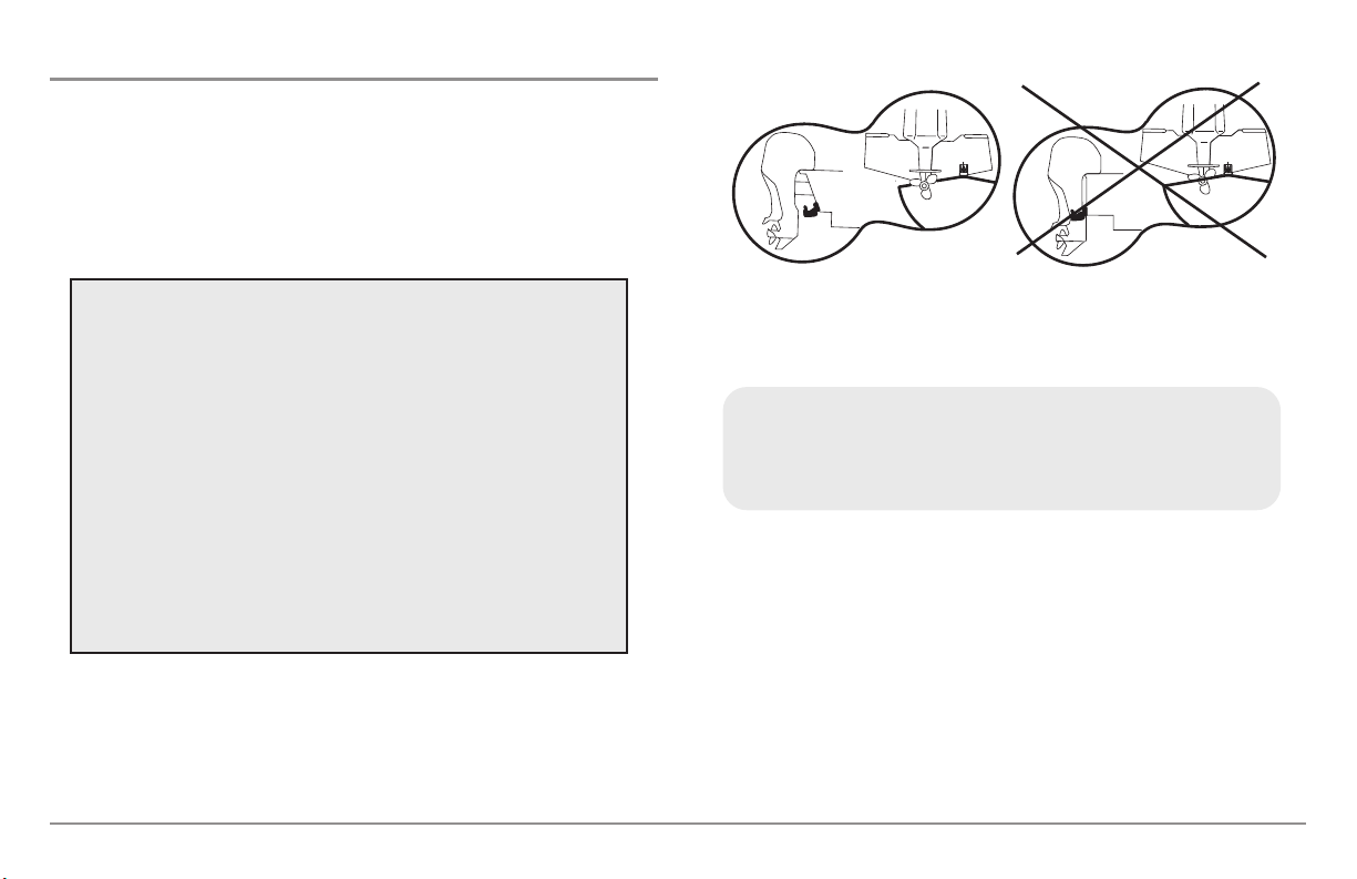
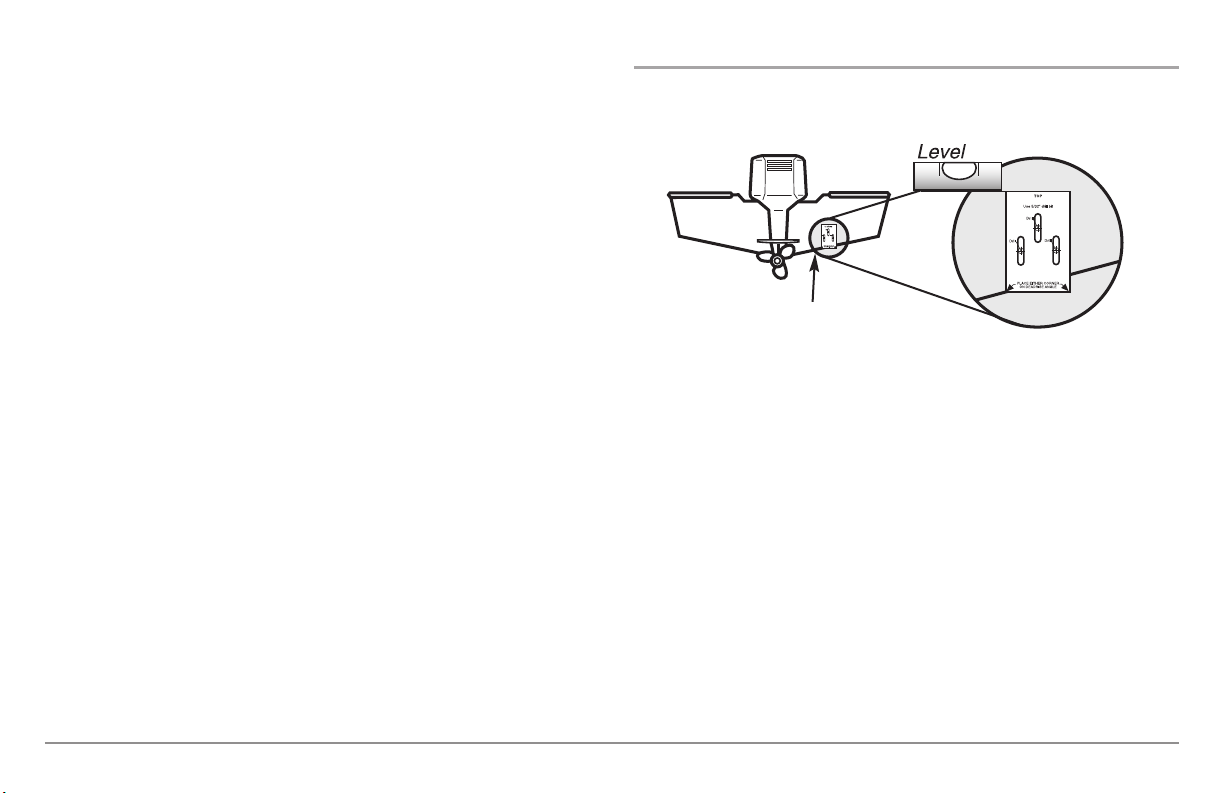
Transducer Mount Position
The Side Imaging transducer has some special requirements
because of its side viewing capabilities:
• The Side Imaging transducer must NOT have anything
obstructing the ‘view’ of the side looking beams, i.e.
nothing can be in the line of sight of these beams (not a
hull, motor, or other transducer, etc).
NOTE: You may need to tilt the motor up and out of the way when
using the side looking beams.
• In order for the side beams to be displayed accurately, the
transducer must be mounted so that it is looking straight
down in the water when the boat is in the water.
Unobstructed View: The jack plate gives
the transducer safe distance from the motor
and turbulence. The side imaging has a
clear view side-to-side.
NOTE: Due to the wide variety of hulls, only general instructions are presented in
this installation guide. Each boat hull represents a unique set of requirements that
should be evaluated prior to installation. It is important to read the instructions
completely and understand the mountingguidelines before beginning installation.
NOTE: If the included transducer will not work for your application, you may exchange it,
NEW and UNASSEMBLED, with mounting hardware included, for a transducer
appropriate for your application - often at very little or no charge depending on the
transducer. Call the Humminbird® Customer Resource Center at 1-800-633-1468 for
details and pricing, or visit www.humminbird.com.
NOTE: In additionto the hardware supplied with your transducer, you will need a powered
hand drill and various drill bits, various hand tools, including a ruler or straightedge, a
marker or pencil, safety glasses and dust mask, and marine-grade silicone sealant.
NOTE: When drilling holes in fiberglass hulls, it is best to start with a smaller bit and use
progressively larger drill bits to reduce the chance of chipping or flaking the outer coating.
13
Obstructed View: The transducer is too
close to motor turbulence, and the side
imaging view is blocked by the motor. The
view cannot extend from side-to-side.
Transom Transducer Installation
If you will be installing a transom mounted transducer, use the procedures
in this section. There are two pieces to the transducer mount assembly: the
pivot, and the bracket. Your transducer comes with a two-piece metal and
plastic bracket assembly. There are several procedures you will have to
perform in order to install a transom-mounted transducer. They are:
To determine transducer mounting location:
NOTE: If transom mounting is not possible because of a stepped hull or
cavitation noise, trolling motor installation may be an option. See Trolling Motor
Transducer Installation for more information.
1. First, determine the best location on the transom to install the
transducer. Consider the following to find the best location:
• Determine transducer mounting location
• Mount the bracket to the boat
• Attach the pivot to the transducer
• Mount the transducer pivot assembly to the bracket
• Adjust the running position of the transducer
• Route the transducer cable
• Perform a final test of the transom transducer installation.
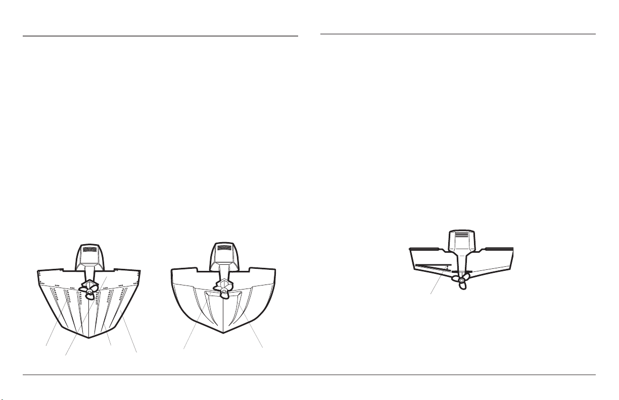
Areas of Possible Turbulence
Rivets Strakes
Transom Hull
Stepped Hull
Step Rib
• It is very important to locatethe transducer in an areawhich is relatively
free of turbulent water. As a boat moves through the water, turbulence
is generatedby the weight of the boat, and the thrust of the propeller(s)
- eitherclockwise or counter-clockwise. Thisturbulent water is normally
confined to areasimmediately aft of ribs,strakes or rowsof rivets on the
bottom of the boat, and in the immediate area of the propeller(s).
Clockwise propellers create more turbulence on the port side. On
outboard or inboard/outboard boats, it is best to locate the transducer
at least 15" (380 mm) to the side of the propeller(s).
Deadrise Angle
• The best way to locate turbulence-free water is to view the transom
while the boat is moving. This method is recommended if maximum
high-speed operation is a high priority. If this is not possible, select a
location on the transom where the hull forward of this location is
smooth, flat and free of protrusions or ribs.
14
• The hydrodynamic shape of your transducer allows it to point straight
down without deadrise adjustment.
• On boats with stepped hulls, it may be possible to mount the transducer on the step. Do not mount the transducer on the transom
behind a step to avoid popping the transducer out of the water at
higher speeds; the transducer must remain in the water for the
control head to maintain the sonar signal.
• If the transom is behind the propeller(s), it may be impossible to find
an area clear from turbulence, and a different mounting technique or
transducer type should be considered (see Trolling Motor
Transducer Installation).
• The Side Imaging transducer must NOT have anything obstructing
the ‘view’ of the side looking beams, i.e. nothing can be in the line
of sight of these beams (not a hull, motor, or other transducer, etc).
To mount the transducer bracket to the boat:
1. Remove the transducer mounting template from this manual. See
Appendix A for the Transducer Mounting Template.
15” (380 mm) from prop(s)
2. Hold the template on the transom of the boat in the location where
the transducer will be installed. Align the template vertically,
matching the lower edge of the transom with the bottom corner of
the template. If your propeller moves clockwise as the boat moves
forward, mount the transducer on the starboard side, and use the
bottom left corner of the template. If your propeller moves counterclockwise as the boat moves forward, mount the transducer on the
port side, and use the bottom right corner of the template.
3. Using a pencil or punch, mark the three mounting holes on the
transom. Do not mark or drill any other holes at this time.
4. Using a 5/32" (4.0 mm) bit, drill the three holes to a depth of
approximately 1" (25 mm). On fiberglass hulls, it is best to use
progressively larger drill bits to reduce the chance of chipping or
flaking the outer coating. Use a marine-grade silicone sealant to fill
the drilled holes.
15
Attaching the Bracket
3
5. Align the metal mounting bracket with the mounting holes. The center
slot should be above the two outer slots. (This bracket and all other
hardware supplied is top quality stainless steel for maximum strength
and corrosionprotection.) Insert the three #10 - 1" long screwsinto the
drilled holes, but do not completely tighten.
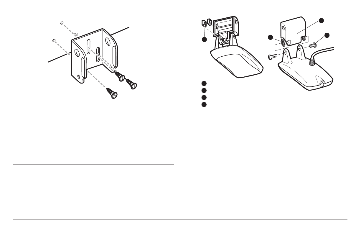
To attach the pivot to the transducer:
1. Attach the pivot to the transducer body, using the two 1/4"-20 x 5/8"
(16 mm) machine screws, toothed washers, and square nuts. The
toothed washers must fit on the inside of the transducer ears,
between the pivot and the ears. The square nuts will be prevented
from rotating by the pocket in the back of the pivot. An Allen wrench
is provided which fits all the 1/4"-20 screws, but do not fully tighten
the screws at this time.
1
Insert the square nuts
1
Toothed Washer
2
Pivot
3
Machine Screw
4
2
Attach the Pivot
4
16
To mount the transducer pivot assembly to the bracket:
1. Slide the assembled transducer into the metal bracket from the
bottom, aligning the large hole at the top of the bracket with the
hole in the pivot.
2. Insert the headed pin through the pivot holes in the bracket and
pivot. The headed pin can be inserted from either side of the
bracket.
3. Place the nylon washer over the opposite end of the headed pin.
Place the stainless washer over the 1/4"-20 x 5/8" (16 mm) screw
threads, then insert into the opposite end of the headed pin and
finger tighten only. The screw has a thread locking compound on the
threads to prevent loosening, and should not be fully tightened until
all adjustments are made.
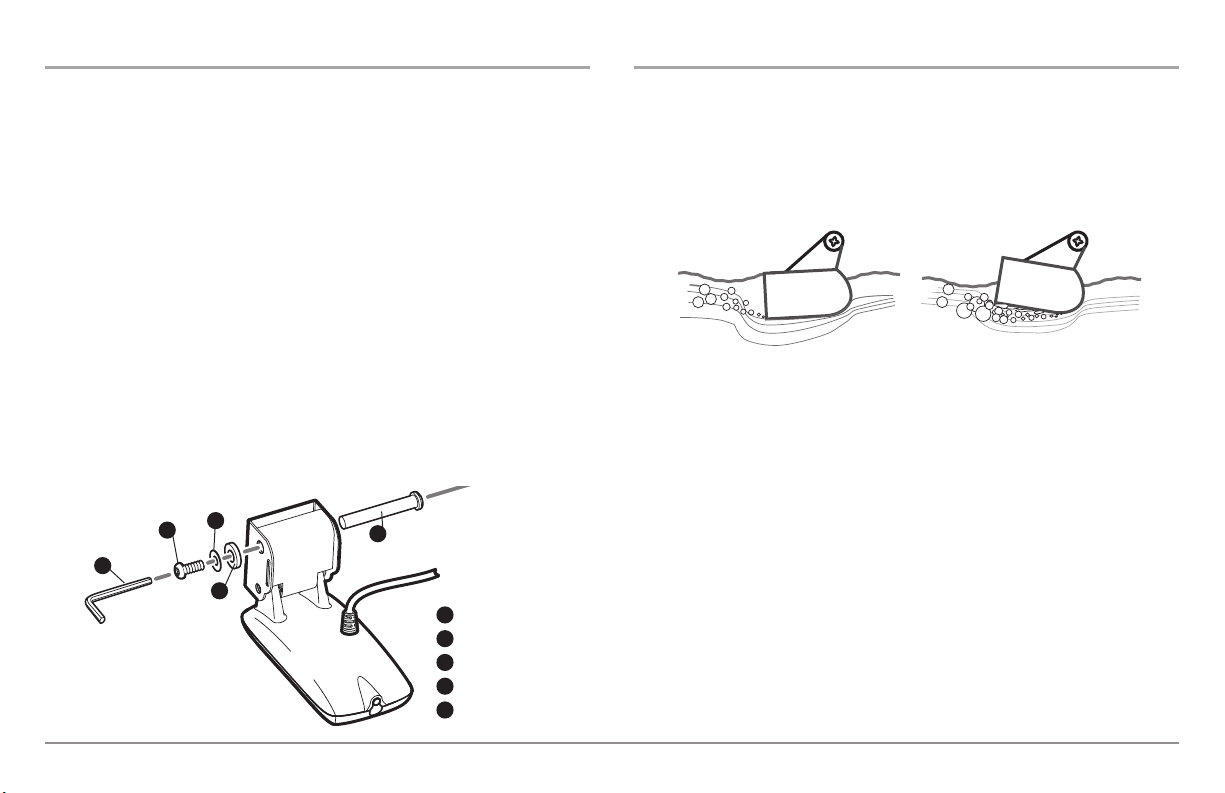
To adjust the running position of the transducer:
The transducer mounting bracket allows height and tilt adjustment, while
the pivot bolt allows angular adjustment. These adjustments will help
reduce cavitation. Initially, adjust the transducer as described in the
following paragraphs. Further adjustment may be necessary to refine the
installation after high-speed testing.
Normal Cavitation Cavitation that will cause
erratic sonar readings
NOTE: The running position of the transducer is now completely adjustable.
Subsequent adjustment may be necessary to tweak the installation after high
speed testing.
5
1
3
4
2
Screw
1
Headed Pin
2
Allen Wrench
3
Nylon Washer
4
Stainless Washer
5
1. First, adjust the pivot angle of the transducer body, so it is parallel
with the length of the hull of the boat.
2. Fully tighten the two pivot screws, using the supplied Allen wrench.
Access to the pivot screws is provided by the lower holes in the side
of the mounting bracket. It may be necessary to re-tighten the pivot
bolt after initial use as the plastic may still be conforming to the
pressure from the lock washers.
17

3. Adjust the height of the assembly so the face of
the transducer is 1/8" (3 mm) to 1/4" (6 mm)
beneath the bottom of the transom, and fully
tighten the three mounting screws.
4. In order to gain access to the mounting screws,
the transducer assembly must be pivoted up in the
Tighten the Mounting
Screws
bracket as shown. Be careful not to alter the
running angle as some force is necessary to pivot
the assembly.
5. If access to the top mounting hole is not possible due to the selected
height of the transducer, fully tighten the two lower screws, then
simply remove the headed pivot pin and the transducer assembly,
and tighten the top screw, then reassemble.
6. Confirm that the pivot angle has not changed and that all mounting
screws are fully tightened.
To route the transom transducer cable:
The transducer cable has a low profile connector that must be routed to the
point where the control head is mounted. There are several ways to route the
transducer cable to the area where the control head will be installed. The
most common procedure routes the cable through the transom into the boat.
1. Unplug the other end of the transducer cable from the control head.
Make sure that the cable is long enough to accommodate the
planned route by running the cable over the transom.
CAUTION! Do not cut or shorten the transducer cable, and try not to damage the
cable insulation. Route the cable as far as possible from any VHF radio antenna
cables or tachometer cables to reduce the possibility of interference. If the cable
is too short, extension cables are available to extend the transducer cable up to
a total of 50' (15 m). For assistance, contact the Customer Resource Center at
www.humminbird.com or call 1-800-633-1468 for more information.
NOTE: Since the transducer may need to pivot up to 90° in the bracket if it strikes
an object, make sure there is sufficient cable slack to accommodate this motion.
It is best to route the cable to the side of the transducer so the cable will not be
damaged by the rotation of the transducer.
2. If you will be routing the cable through a hole in the transom, drill a
5/8" diameter (16 mm) hole above the waterline. Route the cable
through this hole, then fill the hole with marine-grade silicone
sealant and proceed to the next step immediately.
NOTE: Your boat may have a pre-existing wiring channel or conduit that you can
use for the transducer cable.
18
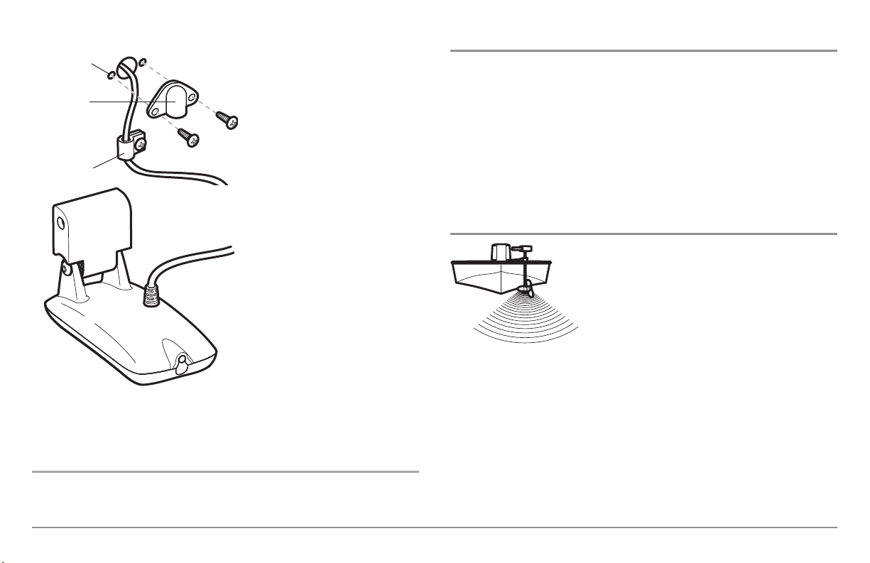
5/8” Hole
Escutcheon
Plate
Cable Clamp
Routing the Cable
3. Place the escutcheon plate over
the cable hole and use it as a guide
to mark the two escutcheon plate
mounting holes. Remove the plate,
drill two 9/64" (3.5 mm) holes, then
fill both holes with marine-grade
silicone sealant. Place the
escutcheon plate over the cable
hole and attach with two #8 x 5/8"
(16 mm) wood screws.
Trolling Motor Transducer Installation
If you want to install the transducer on a trolling motor, use this procedure.
Several styles of the transducer are compatible with trolling motor mounting.
If you have a trolling motor bracket, refer to the separate installation
instructions that are included with the bracket.
NOTE: After trolling motor transducer installation, please perform the final
testing and then finalize the installation (see Test and Finish the Transducer
Installation).
4. Route and secure the cable by
attaching the cable clamp to the
transom; drill one 9/64" dia. (3.5
mm) x 5/8" deep (16 mm) hole,
then fill hole with marine-grade
silicone sealant, then attach the
cable clamp using a #8 x 5/8" (16
mm) screw.
5. Plug the other end of the
transducer cable back into the
control head connection holder.
To perform a final test of the
transom transducer installation:
After transom transducer installation, please perform the final testing and then
finalize the installation (see Test and Finish the Transducer Installation).
Trolling Motor Transducer Options
If you don’t have a trolling motor transducer,
there are several options:
• You may purchase a Trolling Motor Adapter kit
that will allow you to mount the transducer on the
trolling motor.
• You may also exchange your NEW and UNASSEMBLED transducer
(with mounting hardware included) for a trolling motor transducer.
There are also several transducer switches available that support the
following configurations:
• Two control heads with one transducer
• Two transducers with one control head.
NOTE: Call the Humminbird® Customer Resource Center (1-800-633-1468) for
details and pricing, or visit www.humminbird.com for more information.
19

Test and Finish the Transducer Installation
When you have installed both the control head, the transducer, and
accessories and have routed all the cables, you must perform a final test
before locking the transducer in place. Testing should be performed with the
boat in the water, although you can initially confirm basic operation with the
boat out of the water.
1. Press the POWER/LIGHT key once to turn the control head on. There
will be an audible chirp when the key is pressed correctly. If the unit
does not power-up, make sure that the connector holder is fully
seated and that power is available.
2. If all connections are correct and power is available, the control
head will enter Normal operation. If no transducer is detected (or
one is not connected), the unit will go into Simulator mode and will
indicate this by displaying the word Simulator on the control head
display.
NOTE: The transducer must be submerged in water for reliable transducer
detection.
3. If the bottom is visible on-screen with a digital depth readout, the
unit is working properly. Make sure that the boat is in water greater
than 2 ft (.6 m) but less than the depth capability of the unit, and
that the transducer is fully submerged, since the sonar signal
cannot pass through air.
4. If the unit is working properly, gradually increase the boat speed to
test high-speed performance. If the unit functions well at low
speeds but begins to skip or miss the bottom at higher speeds, the
transducer requires adjustment. Angling the rear of the transducer
downward and/or lowering the transducer farther into the water
will help achieve depth readings at high speeds. If the left side of
the fish arch is longer than the right side, then the back of the
transducer is angled too far downward. If the right side of the fish
arch is longer than the left side, then the back of the transducer is
angled too far upwards.
NOTE: It may not always be possible to get symmetrical fish arches and high
speed depth readings at the same time. Due to the wide variety of boat hulls,
however, it is not always possible to obtain high speed depth readings.
NOTE: It is often necessary to make several incremental transducer adjustments
before optimum high speed performance is achieved.
Once you have reached a consistently good sonar signal at the desired
speeds, you are ready to lock down the transducer settings.
5. Mark the transducer bracket location on the transom with a pencil,
then pop up the bracket to reveal the mounting screws. Tighten the
stainless steel mounting bracket screws to secure in place.
Hand-tighten only!
20
GPS Receiver Installation
Stem Mounting with an Existing 1" - 14 Thread Stem
To optimize performance of the GPS receiver, mount it in an area that has full
exposure to the sky. The effective area of reception is 10° above the horizon.
Different circumstances determine the mounting method appropriate for
your GPS receiver.
If you have… Then use:
An existing antenna stem with
standard 1" – 14 thread stem
Access for cable routing under
the mounting location
No access under the mounting
location
The pinouts of the pigtail cable are as follows:
• Red Wire, +12V (output voltage only)
• Black Wire, Ground
• White Wire, NMEA Out.
CAUTION! Please use caution before connecting the red +12V wire to any other
NMEA device. This is an output voltage provided by the Fishfinder unit and
GPS receiver and should only be connected to those NMEA devices that need a
12 volt input.
Stem Mount with Existing 1” 14 Thread Stem
Access Under Mounting
Location
No Access Under Mounting
Location
Follow these steps to stem mount the GPS receiver:
NOTE: If you have an existing stem for mounting the GPS receiver, proceed
directly to step 2 of the following procedure.
1. Determine the best location to mount your GPS receiver. Preplan
and test the cable routing to your control head before any drilling or
cutting of your boat surfaces. If you have purchased hardware to
stem mount your GPS receiver, follow the instructions included with
that hardware to mount the stem (antenna pole).
NOTE: AS-EC10 10' extension cables are available from Humminbird® if your
planned routing exceeds 20', (6 m). Maximum cable length, including extensions,
should not exceed 50' (16 m).
NOTE: Remember to caulk or seal screw holes and drilled holes as needed to
protect your boat from water damage.
1
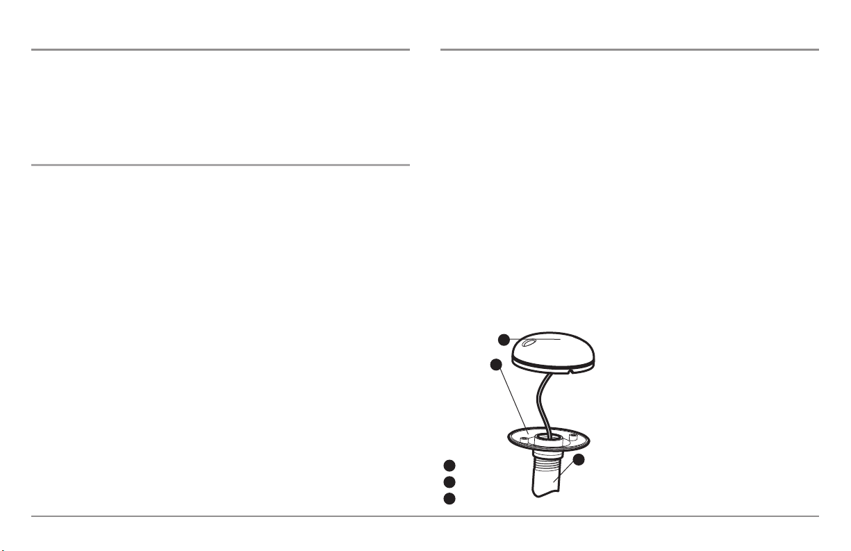
2. Screw on the receiver base to the stem
first, making sure that the stem pipe does
2
not protrude from the receiver base. This
adds protection to the cable when pulling it
through the pipe stem. In addition to this,
de-burr the pipe edges to reduce cable
abrasion.
Receiver
1
Receiver Base
2
Stem Pipe
3
3
21
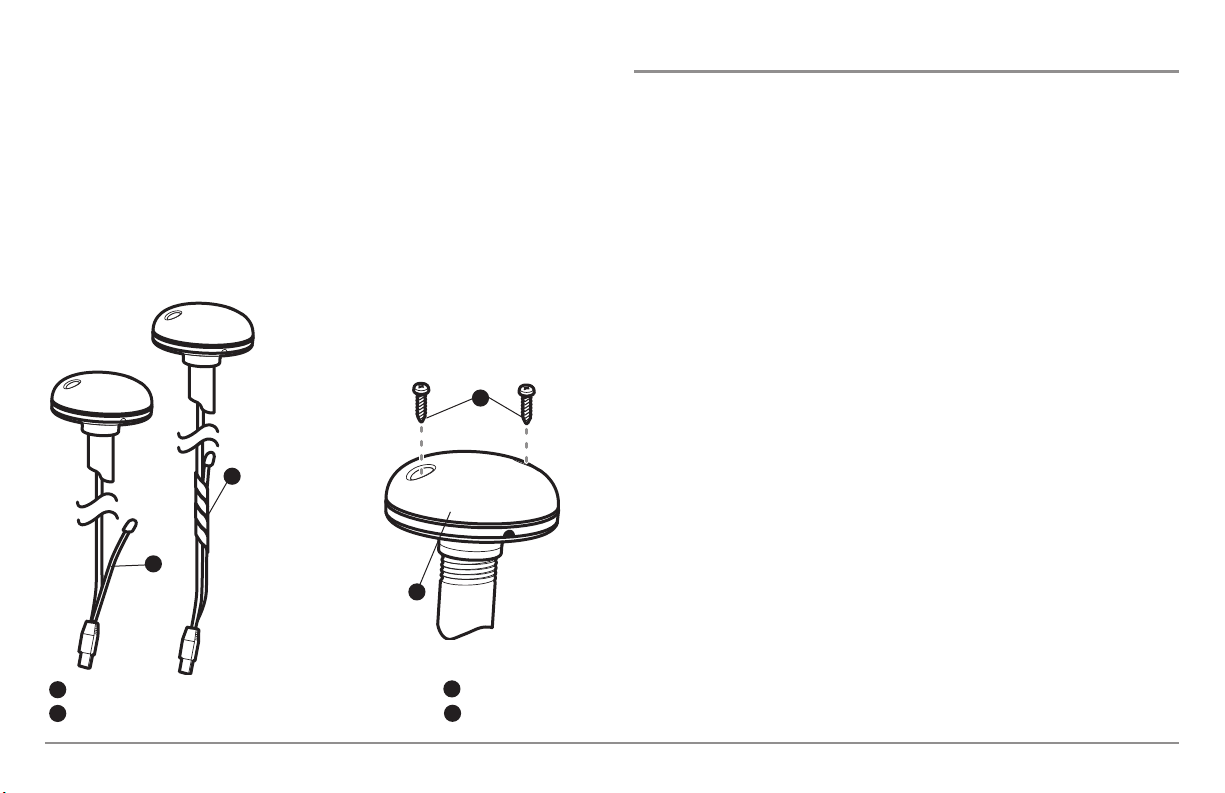
3. Use electrical tape to secure the NMEA pigtail to the cable as
shown.
NOTE: Leave the NMEA pigtail secured to the cable unless needed. This will
make removing the receiver easier.
4. Route the GPS receiver cable through the stem and continue with
the planned route you chose in step 1.
5. Attach the GPS receiver to its base using the included #6 - 7/8"
screws.
3
1
Access Under Mounting Location
Follow these steps to deck mount the GPS receiver when routing the cable
down through the mounting location:
1. Determine the best location, then test route the 20' (6 m) cable from
the mounting location to the control head.
NOTE: Installation details may vary with unit configuration.
2. Mark the mounting location and drill a 3/4" (19 mm) hole for the
cable and cable plug. Route the cable.
3. Cover the cable hole with the receiver. Make sure the receiver is
flush on the surface and mark the two mounting holes with a pencil
or punch.
4. Move the receiver to the side and drill two pilot holes using a 9/64"
(3.5 mm) bit.
NOTE: Remember to caulk or seal screw holes and drilled holes as needed to
protect your boat from water damage.
NMEA Pigtail Taped
1
NMEA Pigtail Cable Out
2
2
4
Mounting Screws
3
Cable Route
4
5. Align the GPS receiver screw holes over the pilot screw holes and
attach with the #8 - 1 1/4" Phillips head screws. Hand tighten only!
NOTE: If the mounting surface is thin and made of a lighter material, a backing
material may be needed below the mounting surface.
22
 Loading...