

Humminbird 800, 900 User Manual
1
800 Series™ & 900 Series™ In-Dash Mounting Kit
Overview
Following are instructions for the installation of this accessory. Before you start the installation, we encourage you to
read these instructions carefully in order to get the full benefit from your Humminbird® accessory.
Customer Service: If you find that any items are missing from your installation kit, visit our Web site at
humminbird.com
Supplies: In addition to the hardware supplied with your In-Dash Mounting Kit, you will need a reciprocating saw
for cutting the dash material and masking tape to hold the mounting template in place.
or call Customer Service at
1-800-633-1468
.
Installation
Start by placing the components on the surfaces where you intend to install them before installation. Make sure that
the surfaces you have chosen provide adequate protection from wave shock, and that all cables can reach the
control head.
NOTE: If a cable is too short for your application, extension cables are available. Contact Customer Service for more
information.
1.In-Dash Mount the Control Head
1. Locate a suitable, flat area of the dash to mount the control head. The control head requires a depth of at least
3 1/2 inches.
531589-2_A
2. Tape the paper In-Dash Mounting Template to the desired in-dash mounting location.
3. At a location inside the dotted line on the template, drill a hole large enough to insert blade of reciprocating
saw. Carefully begin cutting toward the dotted line, then follow the dotted line around the template. Remove
the template when finished.
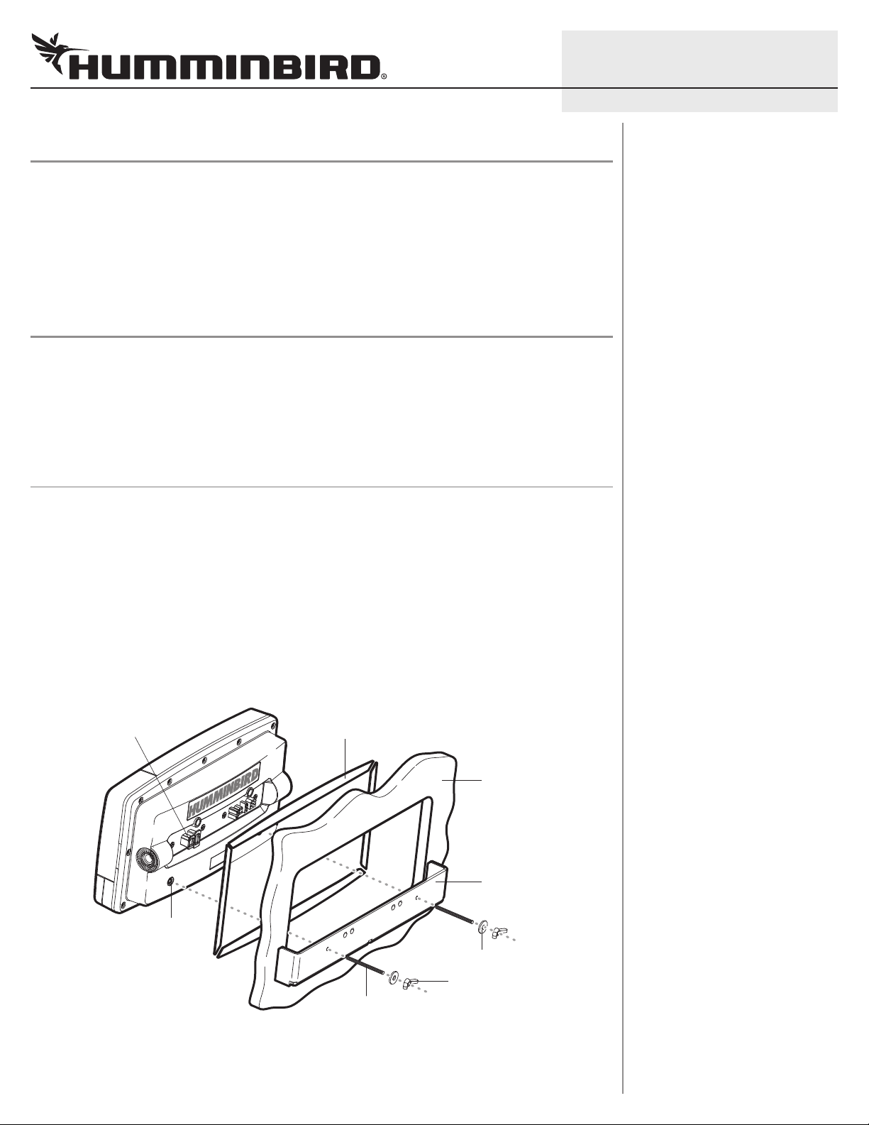
4. Insert and tighten the two threaded rods into the two threaded inserts located on the back side of the control
head. Peel off the adhesive-backed foam pads and place them on the back of the control head; make sure you
notice the difference between the longer top/bottom and shorter side pads.
expansion ports use for future
accessories
threaded insert
foam pads
cut away dash
in-dash bracket
washers
wing nut
threaded rod
5. Insert the control head through the mounting hole from the front side of the dash. From the back side of the
dash, align the two threaded rods on the rear of the housing with the two holes on the in-dash mounting
bracket. Place a washer onto each threaded rod, then secure the bracket by placing a wing nut onto each
threaded rod and tighten fully.
2
800 Series™ & 900 Series™ In-Dash Mounting Kit
2.Route and Connect the Cables
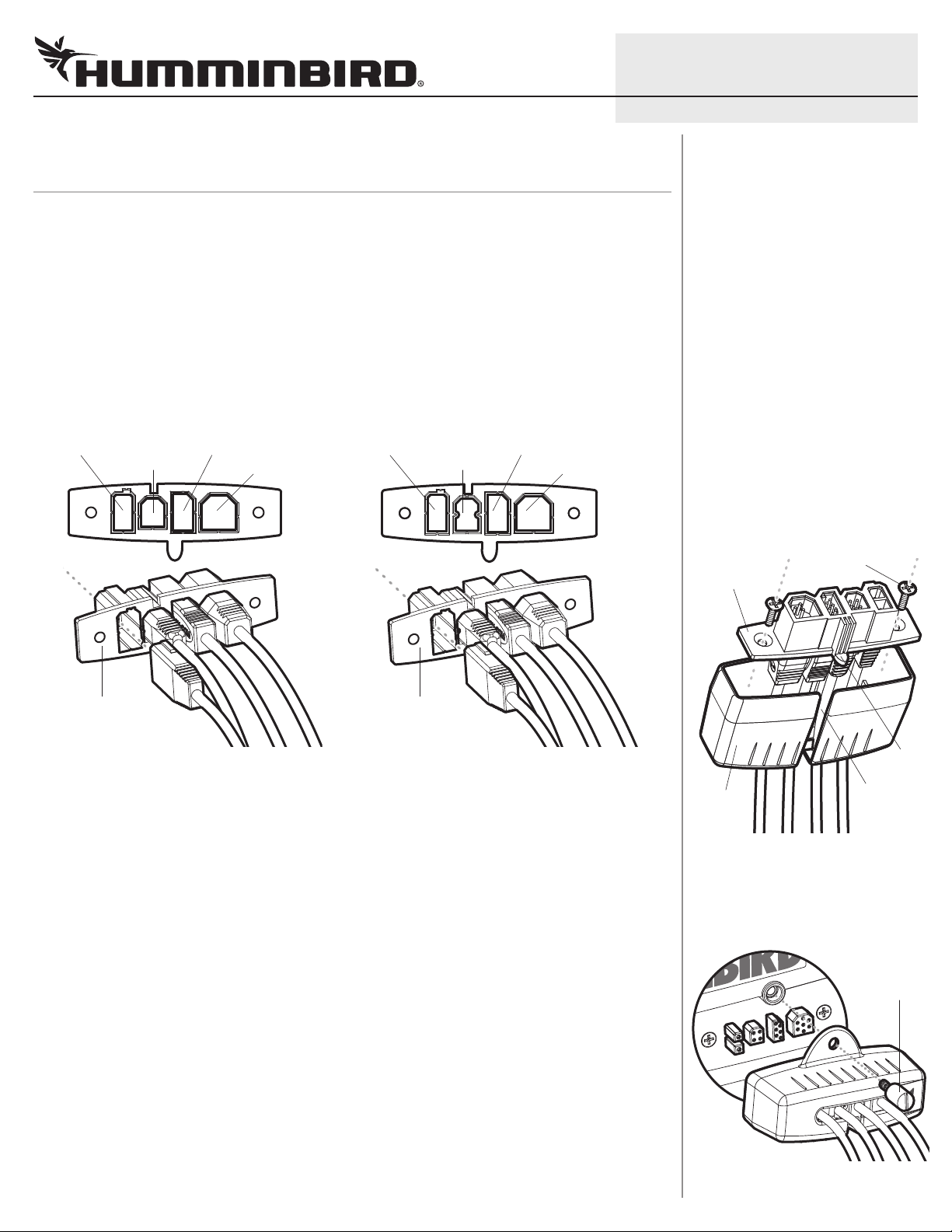
. Refer to the illustrations Connector Holder (A) and Connector Holder (B), and check the second port (from
1
the left) on your connector holder. Confirm which connector holder you have, and proceed to step 2.
2. Insert cable connectors into the proper recesses on the cable collector insert. The cable connectors are keyed
to prevent reverse installation, so be careful not to force the connectors into the wrong slots. If you don’t have
a cable for every hole in the insert, install the blank plugs to protect the unit from the weather.
CONNECTOR HOLDER (B) NOTE: If you are installing the Speed Sensor accessory, insert the Sonar/Speed
Y-Cable connector into the Transducer slot on the cable collector insert. Then, connect the transducer connector
and speed sensor connector to the corresponding connectors on the Y-Cable. The Y-Cable requires a separate
purchase.
Connector Holder (B)
COM (communications)
ethernet
transducer
power
Connector Holder (A)
COM (communications)
temp/speed
power
transducer
Assembling the Cable Collector
Connector Holder (A) displayed below
cable collector
insert
531589-2_A
screws
cable collector
insert
cable collector
insert
NOTE: Connector Holder (B) has an Ethernet slot, but your control head model might not include Ethernet
capability. See our Web site at humminbird.com for product details or contact Customer Service for assistance.
3. While holding cables in place in the cable collector insert, thread the cables through the slot in the bottom of
the cable collector cover, line up the cable collector insert and cover, then slide the cover into place on the insert.
NOTE: The tab on the cable collector insert goes into the slot on the cover.
4. Attach the cable collector insert to the cable collector cover using the 2 Phillips screws provided.
5. Plug the cable collector assembly into the back of the control head. Cable connectors and cable sockets are
keyed to prevent reverse installation, so be careful not to force the connectors into the wrong sockets.
6. Once the cable collector and all cables are plugged into the back of the control head, lock the assembly into
place by threading the knurled screw into the threaded insert on the back of the housing. Cable ties are provided
to help you secure the cables in place by threading them through the available holes on the in-dash bracket.
NOTE: It is very important that the cable collector is used and secured in place in the in-dash installation.
cable
collector
cover
Plug Cable Collector Assembly
to Back of Control Head
Connector Holder (A) displayed below
tab on insert
slot on cover
knurled
screw
 Loading...