

Page 1
757c, 787c2and 787c2i GPS
Chartplotter Operations Manual
757c, 787c2and 787c2i GPS
Chartplotter Operations Manual
531528-1_A
531528-1_A - 757c_787c2_&_787c2i_Man_Eng.qxp 10/16/2006 10:41 AM Page 1
www.reelschematic.com
www.reelschematic.com
Page 2
i
Thank You!
Thank you for choosing Humminbird®, America's #1 name in fishfinders.
Humminbird® has built its reputation by designing and manufacturing topquality, thoroughly reliable marine equipment. Your Humminbird® is designed
for trouble-free use in even the harshest marine environment. In the unlikely
event that your Humminbird® does require repairs, we offer an exclusive
Service Policy - free of charge during the first year after purchase, and
available at a reasonable rate after the one-year period. For complete details,
see the separate warranty card included with your unit. We encourage you to
read this operations manual carefully in order to get full benefit from all the
features and applications of your Humminbird® product.
Contact our Customer Resource Center at either 1-800-633-1468 or visit our
website at www.humminbird.com.
WARNING! This device should not be used as a navigational aid to prevent collision,
grounding, boat damage, or personal injury. When the boat is moving, water depth may
change too quickly to allow time for you to react. Always operate the boat at very slow
speeds if you suspect shallow water or submerged objects.
WARNING! Disassembly and repair of this electronic unit should only be performed by
authorized service personnel. Any modification of the serial number or attempt to repair the
original equipment or accessories by unauthorized individuals will void the warranty.
Handling and/or opening this unit may result in exposure to lead, in the form of solder.
WARNING! This product contains lead, a chemical known to the state of California to cause
cancer, birth defects and other reproductive harm.
DualBeam PLUS™, CannonLink™, Fish ID+™, Fishing GPS®, Humminbird®, HumminbirdPC™,
InterLink™, QuadraBeam PLUS™, RTS® Window, Selective Fish ID+™, WeatherSense®,
WhiteLine®, WideSide®, X-Press™ Menu, and Structure ID® are trademarked by or registered
trademarks of Humminbird®.
© 2006 Humminbird®, Eufaula AL, USA. All rights reserved.
NOTE: Some features discussed in this manual require a separate purchase,
and some features are only available on international models. Every effort has
been made to clearly identify those features. Please read the manual carefully
in order to understand the full capabilities of your model.
531528-1_A - 757c_787c2_&_787c2i_Man_Eng.qxp 10/16/2006 10:41 AM Page 2
www.reelschematic.com
www.reelschematic.com
Page 3
ii
How Sonar Works 1
DualBeam PLUS™ Sonar .......................................................................................................... 3
QuadraBeam PLUS™ Sonar (with optional-purchase QuadraBeam PLUS™ transducer) ........ 4
WideSide® Sonar (with optional-purchase WideSide® transducer) .......................................... 5
Universal Sonar 2 ...................................................................................................................... 5
How GPS and Cartography Work 6
Multi-Media Card (MMC)/SD Slot 8
Software Updates ...................................................................................................................... 8
What’s On the Display 9
Views 11
Sonar View .............................................................................................................................. 12
Understanding Sonar History.................................................................................................. 13
Real Time Sonar (RTS®) Window............................................................................................ 14
Freeze Frame and Cursor ........................................................................................................ 14
Bottom Presentation................................................................................................................ 15
Sonar Zoom View ....................................................................................................................18
200/83 kHz Split Sonar View .................................................................................................. 19
Big Digits View ........................................................................................................................ 20
Circular Flasher View .............................................................................................................. 21
Snapshot and Recording View................................................................................................ 22
Side Beam View (with optional-purchase QuadraBeam PLUS™ transducer).......................... 27
WideSide® View (with optional-purchase WideSide® transducer) .......................................... 30
Bird's Eye View ........................................................................................................................ 31
Chart View................................................................................................................................ 32
Combo View ............................................................................................................................ 34
View Orientation ...................................................................................................................... 35
Viewing Cartography 35
Table of Contents
531528-1_A - 757c_787c2_&_787c2i_Man_Eng.qxp 10/16/2006 10:41 AM Page 3
www.reelschematic.com
www.reelschematic.com
Page 4
iii
Introduction to Navigation 37
Waypoints, Routes and Tracks ................................................................................................ 37
Save, Edit or Delete a Waypoint ............................................................................................ 38
Navigate to a Waypoint or Position ........................................................................................ 39
Add a Waypoint Target or Trolling Grid .................................................................................. 40
Save, Edit or Delete a Route....................................................................................................42
Save or Clear a Current Track .................................................................................................. 43
Edit, Delete or Hide Saved Tracks .......................................................................................... 43
Man Overboard (MOB) Navigation ........................................................................................ 44
Key Functions 46
POWER/LIGHT Key .................................................................................................................. 46
VIEW Key ................................................................................................................................ 46
INFO Key .................................................................................................................................. 47
MENU Key .............................................................................................................................. 47
4-WAY Cursor Control Key ...................................................................................................... 48
MARK Key ................................................................................................................................ 48
GOTO Key.................................................................................................................................. 49
ZOOM (+/-) Key........................................................................................................................ 49
EXIT Key .................................................................................................................................. 50
Accessory Bus 51
Powering Up the Unit 52
The Menu System 53
Start-Up Options Menu 55
Normal Operation .................................................................................................................... 55
Simulator ................................................................................................................................ 56
System Status ........................................................................................................................ 57
Self Test.................................................................................................................................... 57
Accessory Test.......................................................................................................................... 58
GPS Diagnostic View .............................................................................................................. 59
PC Connect (with PC Connect cable only)................................................................................ 60
Table of Contents
531528-1_A - 757c_787c2_&_787c2i_Man_Eng.qxp 10/16/2006 10:41 AM Page 4
www.reelschematic.com
www.reelschematic.com
Page 5
iv
Sonar X-Press™ Menu
(Sonar views only)
61
Side (WideSide® transducer: WideSide® view only) ................................................................ 62
Sensitivity ................................................................................................................................ 63
Upper Range (Advanced: Sonar, Split Sonar, Big Digits and Circular Flasher views only) ...... 64
Lower Range .......................................................................................................................... 65
Side Beam Range (WideSide® transducer: WideSide® view only) .......................................... 66
Chart Speed ............................................................................................................................ 67
Quad Layout (with optional-purchase QuadraBeam PLUS™ transducer,
Side Beam View only).............................................................................................................. 67
Bottom Lock (Sonar Zoom view only) ...................................................................................... 68
Bottom Range (Sonar Zoom view only when Bottom Lock is On) .......................................... 68
Cancel Navigation (only when navigating).............................................................................. 69
Navigation X-Press™ Menu
(Navigation views only)
70
Waypoint [Name] (Only with an active cursor on a waypoint)................................................ 71
Cursor To Waypoint (Chart or Combo view only) .................................................................... 72
Save Current Track .................................................................................................................. 72
Clear Current Track .................................................................................................................. 73
Save Current Route (only when navigating)............................................................................ 73
Skip Next Waypoint (only when navigating) .......................................................................... 74
Cancel Navigation (only when navigating).............................................................................. 74
Cancel MOB Navigation (only when MOB Navigation is activated) ...................................... 75
Remove Target (only if Target is Active) .................................................................................. 75
Remove Grid (only if Grid is Active) .......................................................................................... 76
Sonar Window (Combo view only) .......................................................................................... 76
Waypoint [Name] (Most recently-created waypoint) .............................................................. 77
Snapshot and Recording X-Press™ Menu
(Snapshot and Recording View, optional-purchase MMC/SD card only)
78
Start Recording (optional-purchase MMC/SD Card, Snapshot and Recording View only) ...... 79
Stop Recording (optional-purchase MMC/SD Card)................................................................ 79
Delete Image (optional-purchase MMC/SD card only) ............................................................ 80
Delete All Images (optional-purchase MMC/SD card only) .................................................... 80
Table of Contents
531528-1_A - 757c_787c2_&_787c2i_Man_Eng.qxp 10/16/2006 10:41 AM Page 5
www.reelschematic.com
www.reelschematic.com
Page 6
v
Delete Recording (optional-purchase MMC/SD Card, Snapshot
and Recording View only)........................................................................................................ 81
Delete All Recordings (optional-purchase MMC/SD Card,
Snapshot and Recording View only) ...................................................................................... 81
Pings Per Second (optional-purchase MMC/SD Card,
Snapshot and Recording View only) ...................................................................................... 82
Playback Speed (optional-purchase MMC/SD Card, Snapshot and Recording View only) ...... 82
Stop Playback (optional-purchase MMC/SD Card) .................................................................... 83
Sonar Menu Tab 84
Beam Select ............................................................................................................................ 85
Fish ID+™ ................................................................................................................................ 86
Fish ID Sensitivity .................................................................................................................... 87
Real Time Sonar (RTS®) Window............................................................................................ 87
Bottom View ............................................................................................................................ 88
Zoom Width.............................................................................................................................. 88
83 kHz Sensitivity (Advanced).................................................................................................. 89
455 kHz Sensitivity (Advanced, with QuadraBeam PLUS™ transducer) ................................ 90
WideSide® Sensitivity (Advanced, with WideSide® transducer).............................................. 91
Depth Lines (Advanced) .......................................................................................................... 92
Surface Clutter (Advanced) ...................................................................................................... 93
Noise Filter (Advanced) ............................................................................................................ 94
Max Depth (Advanced) ............................................................................................................ 94
Water Type (Advanced) ............................................................................................................ 95
Transducer Select .................................................................................................................... 95
Navigation Menu Tab 96
Current Track ............................................................................................................................ 97
Saved Tracks ............................................................................................................................ 98
Waypoints ................................................................................................................................ 99
Routes .................................................................................................................................... 100
Chart Orientation.................................................................................................................... 101
North Reference .................................................................................................................... 101
Table of Contents
531528-1_A - 757c_787c2_&_787c2i_Man_Eng.qxp 10/16/2006 10:41 AM Page 6
www.reelschematic.com
www.reelschematic.com
Page 7
vi
Grid Rotation .......................................................................................................................... 101
Trackpoint Interval.................................................................................................................. 102
Track Min Distance (Advanced) ............................................................................................ 102
Track Color Range .................................................................................................................. 103
Map Datum (Advanced) ........................................................................................................ 103
Course Projection Line .......................................................................................................... 104
Export All Nav Data (Advanced) ............................................................................................ 104
Delete All Nav Data (Advanced) ............................................................................................ 105
Continuous Navigation Mode .............................................................................................. 105
Chart Menu Tab 106
Chart Detail Level .................................................................................................................. 107
Map Borders .......................................................................................................................... 108
Lat/Lon Grid............................................................................................................................ 109
Spot Soundings ......................................................................................................................109
Navaids on Bird's Eye View .................................................................................................. 109
Shaded Depth ........................................................................................................................ 110
Set Simulation Position (Advanced) ...................................................................................... 110
Set Map Offset (Advanced).................................................................................................... 111
Clear Map Offset (Advanced) ................................................................................................ 111
Alarms Menu Tab 112
Depth Alarm .......................................................................................................................... 113
Fish ID Alarm.......................................................................................................................... 113
Low Battery Alarm ................................................................................................................ 114
Aux. Temp. Alarm (with optional-purchase temp. probe or Temp/Speed only) .................... 114
Temp Alarm............................................................................................................................ 115
Off Course Alarm .................................................................................................................. 115
Arrival Alarm ........................................................................................................................ 116
Drift Alarm ............................................................................................................................ 117
Alarm Tone ............................................................................................................................ 118
Table of Contents
531528-1_A - 757c_787c2_&_787c2i_Man_Eng.qxp 10/16/2006 10:41 AM Page 7
www.reelschematic.com
www.reelschematic.com
Page 8
vii
Setup Menu Tab 119
Units - Depth.......................................................................................................................... 120
Units - Temp (International only)............................................................................................ 120
Units - Distance...................................................................................................................... 120
Units - Speed.......................................................................................................................... 121
User Mode.............................................................................................................................. 121
Language (International only) ................................................................................................ 121
Triplog Reset .......................................................................................................................... 122
Restore Defaults .................................................................................................................... 122
Select Readouts (Advanced, Sonar view only) ...................................................................... 123
Depth Offset (Advanced)........................................................................................................ 125
Aux. Temp. Offset (Advanced)................................................................................................ 125
Temp Offset (Advanced) ........................................................................................................ 126
Speed Calibration (Advanced, with Temp/Speed only) ........................................................ 126
Local Time Zone (Advanced).................................................................................................. 127
Daylight Saving Time (Advanced).......................................................................................... 127
Position Format (Advanced) .................................................................................................. 128
Time Format (Advanced, International only) .......................................................................... 128
Date Format (Advanced, International only) .......................................................................... 129
Digits Format (Advanced)...................................................................................................... 130
NMEA Output (Advanced)...................................................................................................... 130
Sonar ...................................................................................................................................... 131
Views Menu Tab 132
Accessories Menu Tab 133
Using Screen Snapshot ........................................................................................................ 134
Troubleshooting 136
Fishing System Doesn’t Power Up........................................................................................ 136
Fishing System Defaults to Simulator with a Transducer Attached .................................. 136
Display Problems.................................................................................................................... 137
Finding the Cause of Noise .................................................................................................. 138
531528-1_A - 757c_787c2_&_787c2i_Man_Eng.qxp 10/16/2006 10:41 AM Page 8
www.reelschematic.com
www.reelschematic.com
Page 9

viii
700 Series™ Fishing System Accessories 139
Specifications 141
Glossary 143
Contact Humminbird® 159
NOTE: Entries in this Table of Contents which list (International only) are only available
on products sold outside of the U.S. by our authorized International Distributors. To
obtain a list of authorized International Distributors, please visit our website at
www.humminbird.com or contact our Customer Resource Center at 1-800-633-1468 to locate
the distributor nearest you.
NOTE: Entries in this Table of Contents which list (with PC Connect Cable only) or (with
Optional-Purchase QuadraBeam PLUS™/WideSide® Transducer) or (with Temp/Speed only)
require the purchase of separate accessories. You can visit our website at
www.humminbird.com to order these accessories online or contact our Customer Resource
Center at 1-800-633-1468.
531528-1_A - 757c_787c2_&_787c2i_Man_Eng.qxp 10/16/2006 10:41 AM Page 9
www.reelschematic.com
www.reelschematic.com
Page 10
1
How Sonar Works
Sonar technology is based on sound waves. The 700 Series™ Fishing System
uses sonar to locate and define structure, bottom contour and composition, as
well as depth directly below the transducer.
Your 700 Series™ Fishing System sends a sound wave signal and determines
distance by measuring the time between the transmission of the sound wave
and when the sound wave is reflected off of an object; it then uses the reflected
signal to interpret location, size, and composition of an object.
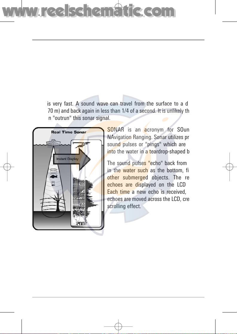
Sonar is very fast. A sound wave can travel from the surface to a depth of
240 ft (70 m) and back again in less than 1/4 of a second. It is unlikely that your
boat can "outrun" this sonar signal.
SONAR is an acronym for SOund and
NAvigation Ranging. Sonar utilizes precision
sound pulses or "pings" which are emitted
into the water in a teardrop-shaped beam.
The sound pulses "echo" back from objects
in the water such as the bottom, fish and
other submerged objects. The returned
echoes are displayed on the LCD screen.
Each time a new echo is received, the old
echoes are moved across the LCD, creating a
scrolling effect.
531528-1_A - 757c_787c2_&_787c2i_Man_Eng.qxp 10/16/2006 10:41 AM Page 10
www.reelschematic.com
www.reelschematic.com
Page 11
2
When all the echoes are viewed side by side, an
easy to interpret "graph" of the bottom, fish and
structure appears.
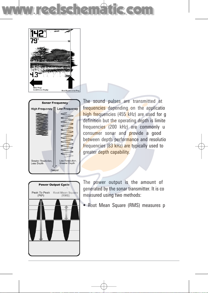
The sound pulses are transmitted at various
frequencies depending on the application. Very
high frequencies (455 kHz) are used for greatest
definition but the operating depth is limited. High
frequencies (200 kHz) are commonly used on
consumer sonar and provide a good balance
between depth performance and resolution. Low
frequencies (83 kHz) are typically used to achieve
greater depth capability.
The power output is the amount of energy
generated by the sonar transmitter. It is commonly
measured using two methods:
• Root Mean Square (RMS) measures power
output over the entire transmit cycle.
• Peak to Peak measures power output at the
highest points.
The benefits of increased power output are the
ability to detect smaller targets at greater
distances, ability to overcome noise, better high
speed performance and enhanced depth capability.
531528-1_A - 757c_787c2_&_787c2i_Man_Eng.qxp 10/16/2006 10:41 AM Page 11
www.reelschematic.com
www.reelschematic.com
Page 12
3
DualBeam PLUS™ Sonar
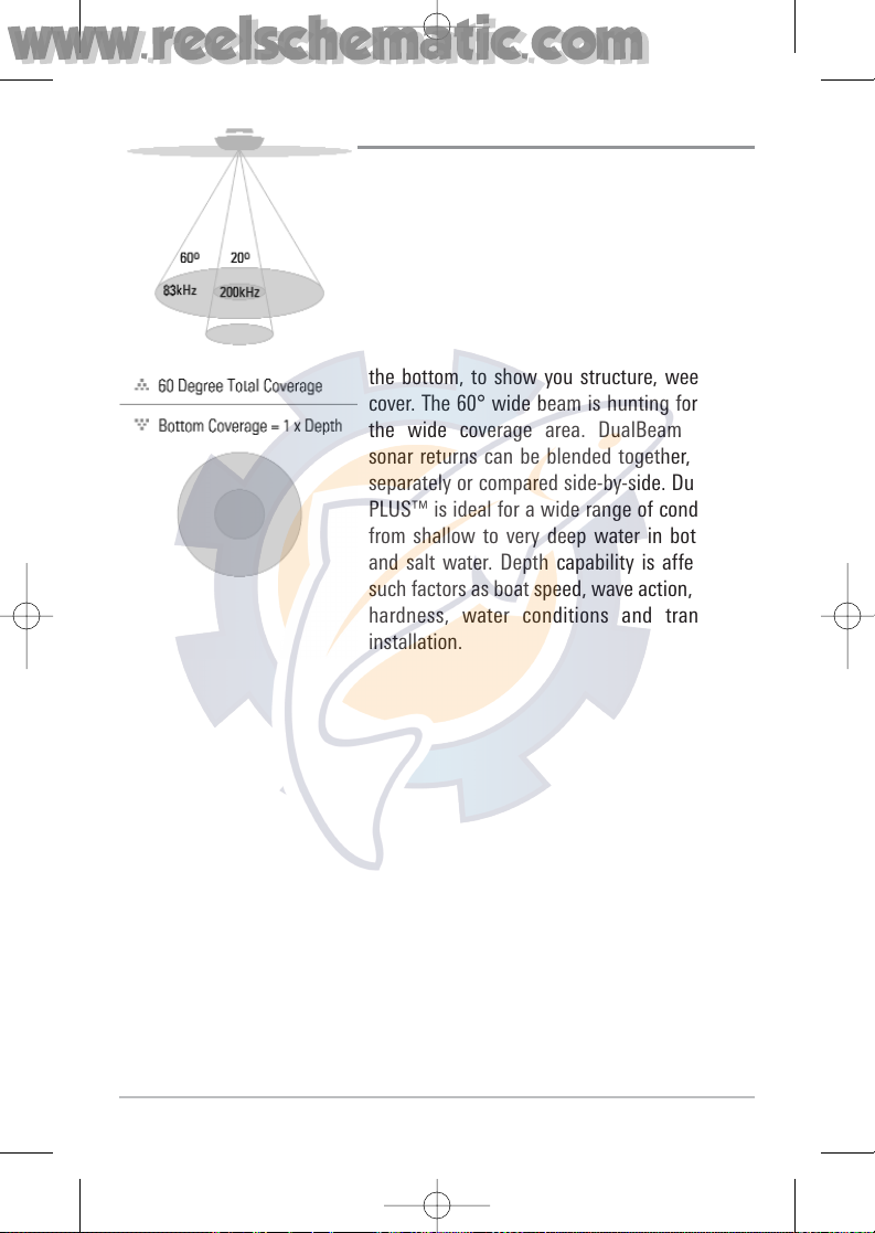
Your 700 Series™ Fishing System uses a 200/83
kHz DualBeam PLUS™ sonar system with a
wide (60°) area of coverage. DualBeam PLUS™
sonar has a narrowly focused 20° center beam,
surrounded by a second beam of 60°, expanding
your coverage to an area equal to your depth. In
20 feet of water, the wider beam covers an area
20 feet wide. The 20° center beam is focused on
the bottom, to show you structure, weeds and
cover. The 60° wide beam is hunting for fish in
the wide coverage area. DualBeam PLUS™
sonar returns can be blended together, viewed
separately or compared side-by-side. DualBeam
PLUS™ is ideal for a wide range of conditions from shallow to very deep water in both fresh
and salt water. Depth capability is affected by
such factors as boat speed, wave action, bottom
hardness, water conditions and transducer
installation.
531528-1_A - 757c_787c2_&_787c2i_Man_Eng.qxp 10/16/2006 10:41 AM Page 12
www.reelschematic.com
www.reelschematic.com
Page 13
4
QuadraBeam PLUS™ Sonar
(with optional-purchase QuadraBeam PLUS™
transducer)
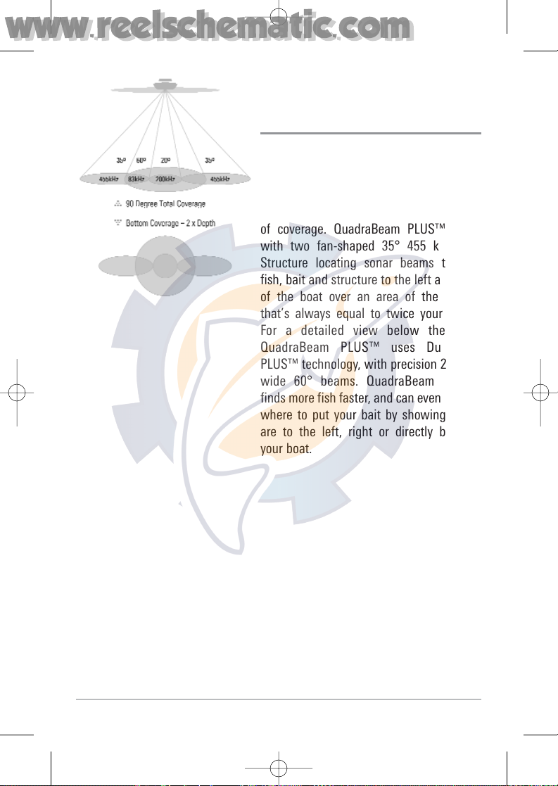
Your 700 Series™ Fishing System also
supports QuadraBeam PLUS™ sonar with
the purchase of an additional QuadraBeam
PLUS™ transducer. QuadraBeam PLUS™
sonar provides an extremely wide 90° area
of coverage. QuadraBeam PLUS™ starts
with two fan-shaped 35° 455 kHz Side
Structure locating sonar beams to spot
fish, bait and structure to the left and right
of the boat over an area of the bottom
that’s always equal to twice your depth.
For a detailed view below the boat,
QuadraBeam PLUS™ uses DualBeam
PLUS™ technology, with precision 20° and
wide 60° beams. QuadraBeam PLUS™
finds more fish faster, and can even tell you
where to put your bait by showing if fish
are to the left, right or directly beneath
your boat.
531528-1_A - 757c_787c2_&_787c2i_Man_Eng.qxp 10/16/2006 10:41 AM Page 13
www.reelschematic.com
www.reelschematic.com
Page 14
5
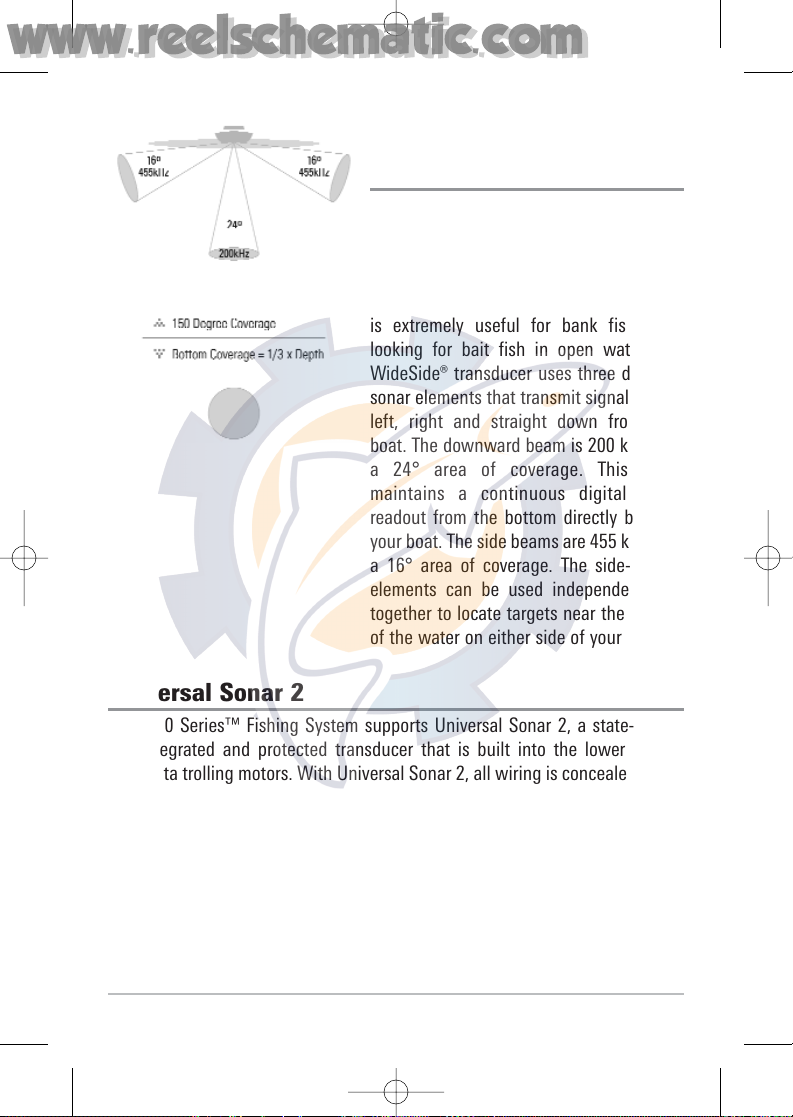
WideSide® Sonar
(with optional-purchase WideSide®
transducer)
Your 700 Series™ Fishing System also
supports WideSide® sonar with the
purchase of an additional WideSide®
transducer. The WideSide® transducer is a
specialized "side-looking" transducer that
is extremely useful for bank fishing or
looking for bait fish in open water. The
WideSide® transducer uses three different
sonar elements that transmit signals to the
left, right and straight down from your
boat. The downward beam is 200 kHz with
a 24° area of coverage. This beam
maintains a continuous digital depth
readout from the bottom directly beneath
your boat. The side beams are 455 kHz with
a 16° area of coverage. The side-looking
elements can be used independently, or
together to locate targets near the surface
of the water on either side of your boat.
Universal Sonar 2
Your 700 Series™ Fishing System supports Universal Sonar 2, a state-of-theart, integrated and protected transducer that is built into the lower unit of
Minnkota trolling motors. With Universal Sonar 2, all wiring is concealed inside
the indestructible composite shaft—out of sight and out of harm’s way, with
no clamps, ties, or exposed wires. Universal Sonar 2 features new temperature
sensing and the performance of DualBeam PLUS™ technology (available with
all Humminbird® DualBeam PLUS™ models). An expanded view and greater
bottom detail gives you a totally new perspective of the water below, along
with optimal sonar performance to help you find fish.
531528-1_A - 757c_787c2_&_787c2i_Man_Eng.qxp 10/16/2006 10:41 AM Page 14
www.reelschematic.com
www.reelschematic.com
Page 15
6
How GPS and Cartography Work
Your 700 Series™ Fishing System also supports GPS and chartplotting, and
uses GPS and sonar to determine your position, display it on a grid, and provide
detailed underwater information. The Global Positioning System (GPS) is a
satellite navigation system designed and maintained by the U.S. Department of
Defense. GPS was originally intended for military use; however, civilians may
also take advantage of its highly accurate position capabilities, typically within
+/- 10 meters, depending on conditions. This means that 95% of the time, the
GPS receiver will read a location within 10 meters of your actual position. Your
GPS Receiver also uses information from WAAS (the Wide Area Augmentation
System), EGNOS (the European Geostationary Navigation Overlay Service), and
MSAS (the MTSAT Satellite Augmentation System) satellites if they are
available in your area.
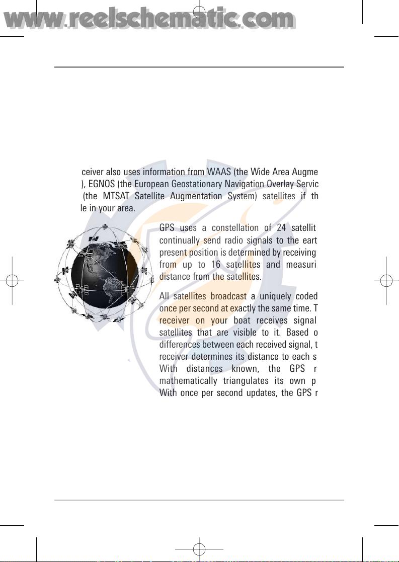
GPS uses a constellation of 24 satellites that
continually send radio signals to the earth. Your
present position is determined by receiving signals
from up to 16 satellites and measuring the
distance from the satellites.
All satellites broadcast a uniquely coded signal
once per second at exactly the same time. The GPS
receiver on your boat receives signals from
satellites that are visible to it. Based on time
differences between each received signal, the GPS
receiver determines its distance to each satellite.
With distances known, the GPS receiver
mathematically triangulates its own position.
With once per second updates, the GPS receiver
then calculates its velocity and bearing.
The GPS Receiver included with your 700 Series™ Fishing System allows you
to cosmbine easy-to-use FishingGPS® chartplotter and navigation capabilities
with advanced fishfinding.
531528-1_A - 757c_787c2_&_787c2i_Man_Eng.qxp 10/16/2006 10:41 AM Page 15
www.reelschematic.com
www.reelschematic.com
Page 16
7
The following GPS functionality is currently supported by the 700 Series™
Fishing System when it is connected to the included GPS receiver:
• View current position
• View current track (breadcrumb trail)
• View precision speed and heading from your GPS receiver
• Save tracks, waypoints and routes
• Travel a route and navigate from one waypoint to the next.
Your 700 Series™ supports Navionics® Gold, HotMaps™ and HotMaps™ Premium
on MMC or SD card media.
NOTE: Your 700 Series™ does not support Navionics® Classic Charts, only Navionics® Gold,
HotMaps™, and HotMaps™ Premium.
Your unit also comes with a built-in Uni-Map™ with a more detailed map of
North America (Domestic models) or a more detailed map of Europe and
Southeast Asia, including Australia and New Zealand (International models).
Your 700 Series™ uses the GPS Receiver to determine the position of the boat
automatically, and uses the zoom level settings on a particular view to select
the best chart to display. See Viewing Cartography for more information.
531528-1_A - 757c_787c2_&_787c2i_Man_Eng.qxp 10/16/2006 10:41 AM Page 16
www.reelschematic.com
www.reelschematic.com
Page 17
8
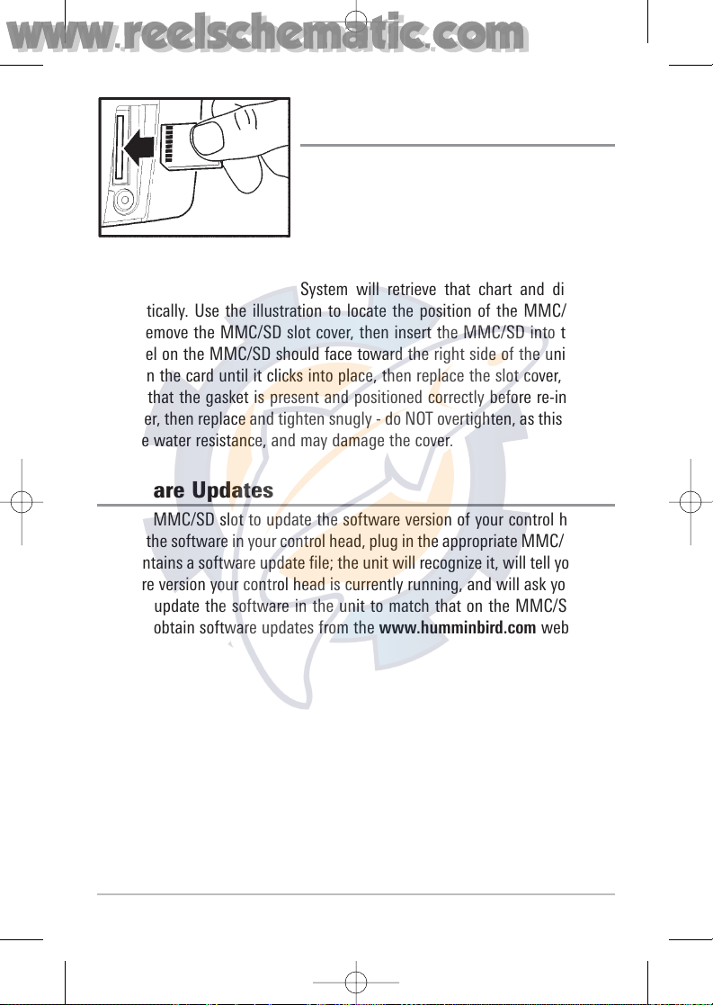
Multi-Media Card
(MMC)/SD Slot
Your 700 Series™ Fishing System also has a
multi-media card (MMC)/SD slot that is used to
insert optional-purchase cards containing
additional detailed maps. If you insert an
MMC/SD that contains a more detailed chart for
a particular location, your 700 Series™ Fishing
System will retrieve that chart and display it
automatically. Use the illustration to locate the position of the MMC/SD slot
cover, remove the MMC/SD slot cover, then insert the MMC/SD into the slot.
The label on the MMC/SD should face toward the right side of the unit. Press
down on the card until it clicks into place, then replace the slot cover, making
certain that the gasket is present and positioned correctly before re-installing
the cover, then replace and tighten snugly - do NOT overtighten, as this will not
improve water resistance, and may damage the cover.
Software Updates
Use the MMC/SD slot to update the software version of your control head. To
update the software in your control head, plug in the appropriate MMC/SD card
that contains a software update file; the unit will recognize it, will tell you what
software version your control head is currently running, and will ask you if you
want to update the software in the unit to match that on the MMC/SD card.
You can obtain software updates from the www.humminbird.com website.
Inserting an MMC/SD
into the Card Slot
531528-1_A - 757c_787c2_&_787c2i_Man_Eng.qxp 10/16/2006 10:41 AM Page 17
www.reelschematic.com
www.reelschematic.com
Page 18
9
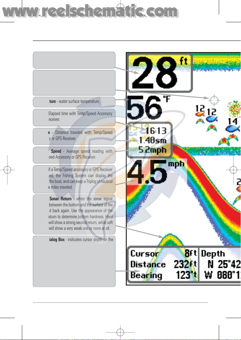
What’s On the Display
The 700 Series™ Fishing System can display a variety of useful information about the a
Depth - water depth; can be set to alarm when the
water becomes too shallow.
Temperature - water surface temperature.
Timer - Elapsed time with Temp/Speed Accessory
or GPS Receiver.
Distance - Distance traveled with Temp/Speed
Accessory or GPS Receiver.
Average Speed - Average speed reading with
Temp/Speed Accessory or GPS Receiver.
Second Sonar Return - when the sonar signal
bounces between the bottom and the surface of the
water and back again. Use the appearance of the
second return to determine bottom hardness. Hard
bottoms will show a strong second return, while soft
bottoms will show a very weak one or none at all.
Speed - if a Temp/Speed accessory or GPS Receiver
is attached, the Fishing System can display the
speed of the boat, and can keep a Triplog of nautical
or statute miles traveled.
NOTE: Entries in this view that list (with Temp/Speed or GPS Receiver) are available if either device
the information from the GPS receiver will be displayed on the view.
Cursor - available in Freeze Frame and can be
positioned in the Sonar View to provide depth of a
sonar return and bottom depth below the cursor.
Cursor Dialog Box - indicates cursor depth on the
display and the depth of the bottom directly below
the cursor. The Latitude and Longitude of the cursor
position, the distance to travel to the cursor
position and the bearing to the cursor position is
shown with a GPS receiver. A waypoint can be
marked at the cursor position for later retrieval and
use with a GPS receiver.
531528-1_A - 757c_787c2_&_787c2i_Man_Eng.qxp 10/16/2006 10:41 AM Page 18
www.reelschematic.com
www.reelschematic.com
Page 19
10
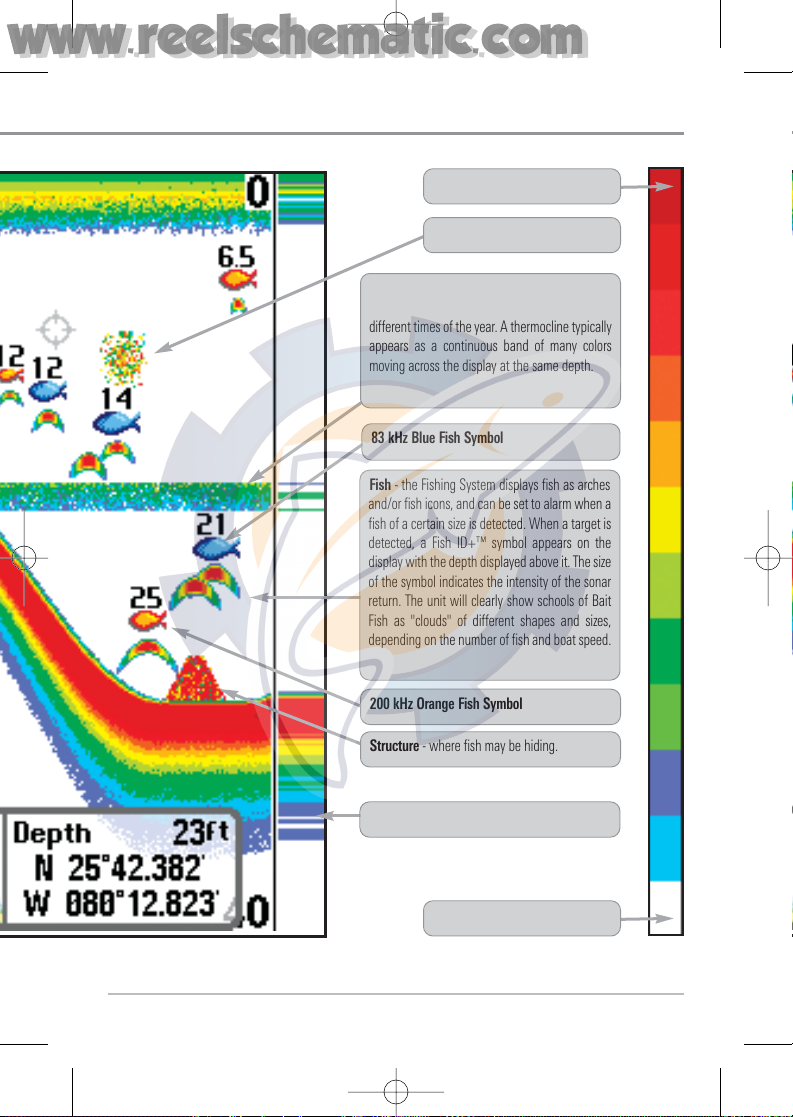
RTS® (Real Time Sonar) Window
Structure - where fish may be hiding.
Thermoclines - layers of water with different
temperatures that appear at different depths and
different times of the year. A thermocline typically
appears as a continuous band of many colors
moving across the display at the same depth.
83 kHz Blue Fish Symbol
Bait Ball
Fish - the Fishing System displays fish as arches
and/or fish icons, and can be set to alarm when a
fish of a certain size is detected. When a target is
detected, a Fish ID+™ symbol appears on the
display with the depth displayed above it. The size
of the symbol indicates the intensity of the sonar
return. The unit will clearly show schools of Bait
Fish as "clouds" of different shapes and sizes,
depending on the number of fish and boat speed.
Low Sonar Intensity Return
High Sonar Intensity Return
200 kHz Orange Fish Symbol
531528-1_A - 757c_787c2_&_787c2i_Man_Eng.qxp 10/16/2006 10:41 AM Page 19
www.reelschematic.com
www.reelschematic.com
Page 20
11
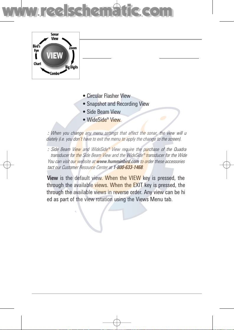
Views
The views available on your Fishing System are:
Sonar vie
ws: Navigation views:
• Sonar View • Bird’s Eye View
• Zoom View • Chart View
• 200/83 kHz Split Sonar View • Combo View.
• Big Digits View
• Circular Flasher View
• Snapshot and Recording View
• Side Beam View
• WideSide® View.
NOTE: When you change any menu settings that affect the sonar, the view will update
immediately (i.e. you don’t have to exit the menu to apply the change to the screen).
NOTE: Side Beam View and WideSide® View require the purchase of the QuadraBeam
PLUS™ transducer for the Side Beam View and the WideSide® transducer for the WideSide®
View. You can visit our website at www.humminbird.com to order these accessories online
or contact our Customer Resource Center at 1-800-633-1468.
Sonar View is the default view. When the VIEW key is pressed, the display
cycles through the available views. When the EXIT key is pressed, the display
cycles through the available views in reverse order. Any view can be hidden or
displayed as part of the view rotation using the Views Menu tab.
531528-1_A - 757c_787c2_&_787c2i_Man_Eng.qxp 10/16/2006 10:41 AM Page 20
www.reelschematic.com
www.reelschematic.com
Page 21
12
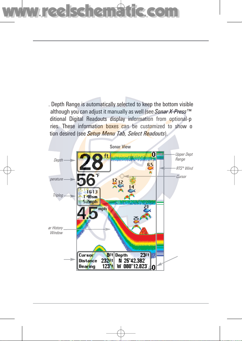
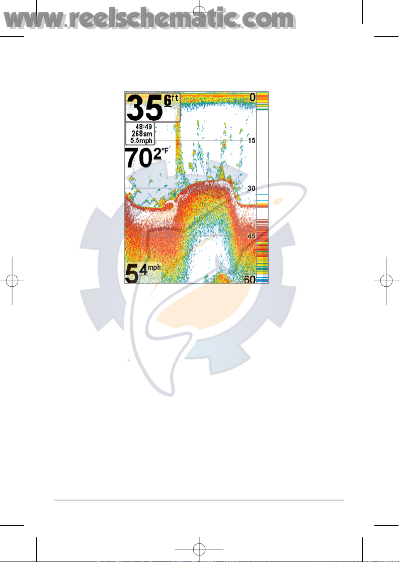
Sonar View
Sonar View presents a historical log of sonar returns. Depth is always displayed.
Readouts for temperature and speed are automatically displayed if the
appropriate accessory is connected. The most recent sonar returns are charted on
the right side of the window; as new information is received, the older
information is moved across the display to the left. A Digital Depth Readout is
displayed in the upper left corner. A scale with Upper and Lower Depth Range
readouts appears along the right edge of the Sonar View. The scale indicates the
distance from the surface of the water to a depth range sufficient to show the
bottom. Depth Range is automatically selected to keep the bottom visible on the
display, although you can adjust it manually as well (see Sonar X-Press™ Menu).
Five additional Digital Readouts display information from optional-purchase
accessories. These information boxes can be customized to show only the
information desired (see Setup Menu Tab, Select Readouts).
NOTE: If the Depth number is flashing, it means that the unit is having trouble locating the
bottom. This usually happens if the water is too deep, the transducer is out of the water, the
boat is moving too fast, or for any other reason that the unit can’t accurately receive
continuous data.
Sonar View
Upper Depth
Range
Sonar History
Window
Depth
Cursor
Dialog Box
Temperature
Triplog
Lower
Depth
Range
RTS® Window
Cursor
531528-1_A - 757c_787c2_&_787c2i_Man_Eng.qxp 10/16/2006 10:41 AM Page 21
www.reelschematic.com
www.reelschematic.com
Page 22
13
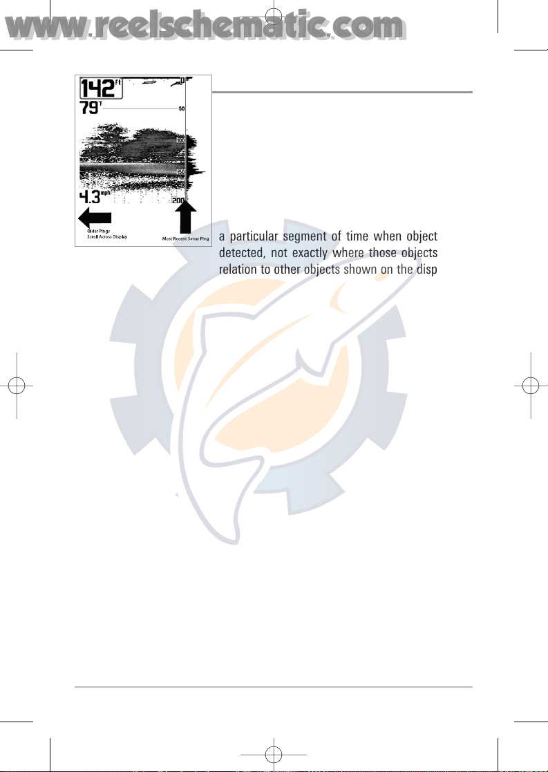
Understanding Sonar History
It is important to understand the significance of
the display. The display does NOT show a literal 3dimensional representation of what is under the
water. Each vertical band of data received by the
control head and plotted on the display represents
something that was detected by a sonar return at
a particular time. As both the boat and the targets
(fish) may be moving, the returns are only showing
a particular segment of time when objects were
detected, not exactly where those objects are in
relation to other objects shown on the display.
531528-1_A - 757c_787c2_&_787c2i_Man_Eng.qxp 10/16/2006 10:41 AM Page 22
www.reelschematic.com
www.reelschematic.com
Page 23
14
Real Time Sonar (RTS®) Window
A Real Time Sonar (RTS®) Window appears on the right side of the display in
the Sonar View only. The RTS® Window always updates at the fastest rate
possible for depth conditions and shows only the returns from the bottom,
structure and fish that are within the transducer beam. The RTS® Window plots
the depth and intensity of a sonar return. (See Sonar Menu: RTS® Window).
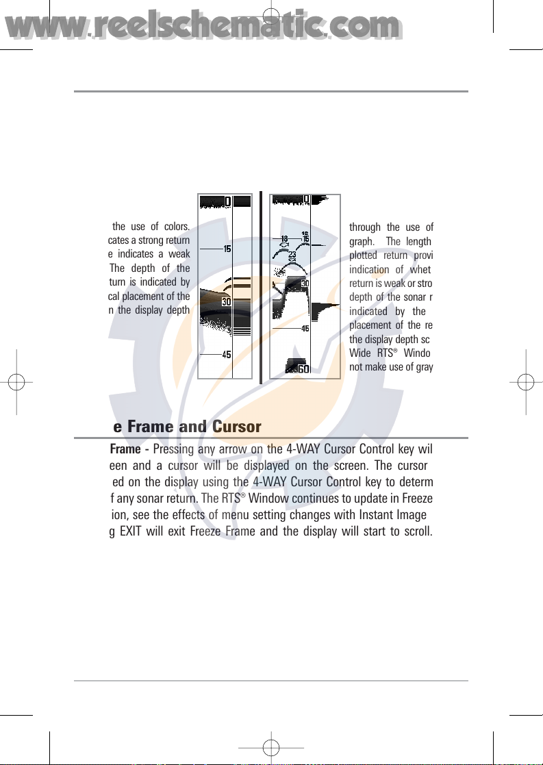
Freeze Frame and Cursor
Freeze Frame - Pressing any arrow on the 4-WAY Cursor Control key will freeze
the screen and a cursor will be displayed on the screen. The cursor can be
positioned on the display using the 4-WAY Cursor Control key to determine the
depth of any sonar return. The RTS® Window continues to update in Freeze Frame.
In addition, see the effects of menu setting changes with Instant Image Update.
Pressing EXIT will exit Freeze Frame and the display will start to scroll. Freeze
Frame is available in the Sonar, Sonar Zoom, and 200/83 kHz Split Sonar Views.
The Narrow RTS® Window
indicates the sonar intensity
through the use of colors.
Red indicates a strong return
and blue indicates a weak
return. The depth of the
sonar return is indicated by
the vertical placement of the
return on the display depth
scale.
The Wide RTS® Window indicates the sonar intensity
through the use of a bar
graph. The length of the
plotted return provides an
indication of whether the
return is weak or strong. The
depth of the sonar return is
indicated by the vertical
placement of the return on
the display depth scale. The
Wide RTS® Window does
not make use of grayscale.
531528-1_A - 757c_787c2_&_787c2i_Man_Eng.qxp 10/16/2006 10:41 AM Page 23
www.reelschematic.com
www.reelschematic.com
Page 24
15
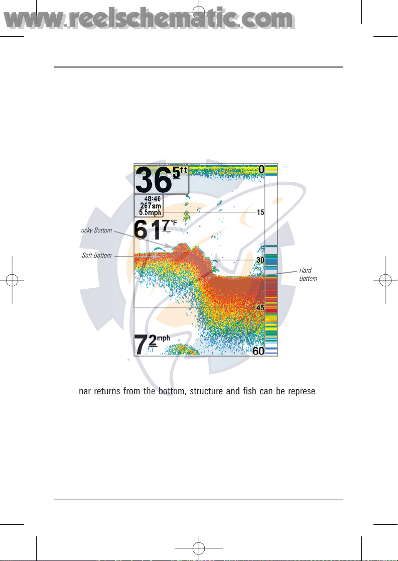
Bottom Presentation
As the boat moves, the unit charts the changes in depth on the display to create
a profile of the Bottom Contour. The type of bottom can be determined from
the return charted on the display. A Hard Bottom such as compacted sediment
or flat rock appears as a thinner line across the display. A Soft Bottom such as
mud or sand appears as a thicker line across the display. Rocky Bottoms have
a broken, random appearance.
The sonar returns from the bottom, structure and fish can be represented as
either WhiteLine® or Structure ID®. See Sonar Menu Tab: Bottom View for
details on how to set the bottom view.
Bottom Contour Profile with RTS® Window.
Rocky Bottom
Hard
Bottom
Soft Bottom
531528-1_A - 757c_787c2_&_787c2i_Man_Eng.qxp 10/16/2006 10:41 AM Page 24
www.reelschematic.com
www.reelschematic.com
Page 25
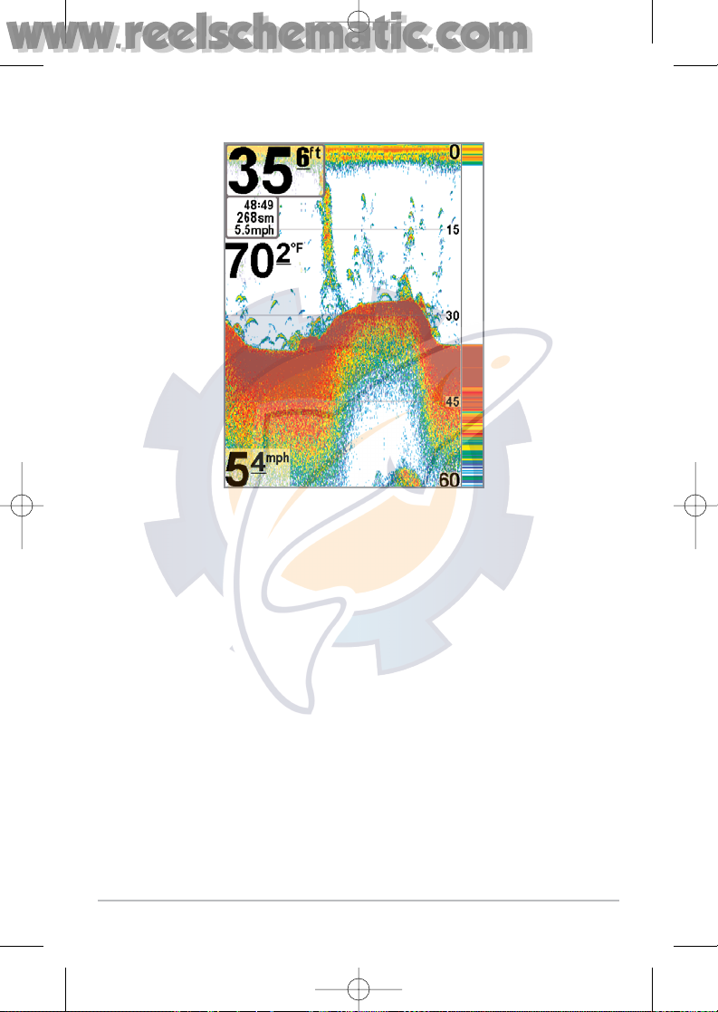
16
Structure ID® represents weak returns in blue and strong returns in red.
531528-1_A - 757c_787c2_&_787c2i_Man_Eng.qxp 10/16/2006 10:41 AM Page 25
www.reelschematic.com
www.reelschematic.com
Page 26
17
WhiteLine® highlights the strongest sonar returns in white, resulting in a distinctive
outline. This has the benefit of clearly defining the bottom on the display.
531528-1_A - 757c_787c2_&_787c2i_Man_Eng.qxp 10/16/2006 10:41 AM Page 26
www.reelschematic.com
www.reelschematic.com
Page 27
18
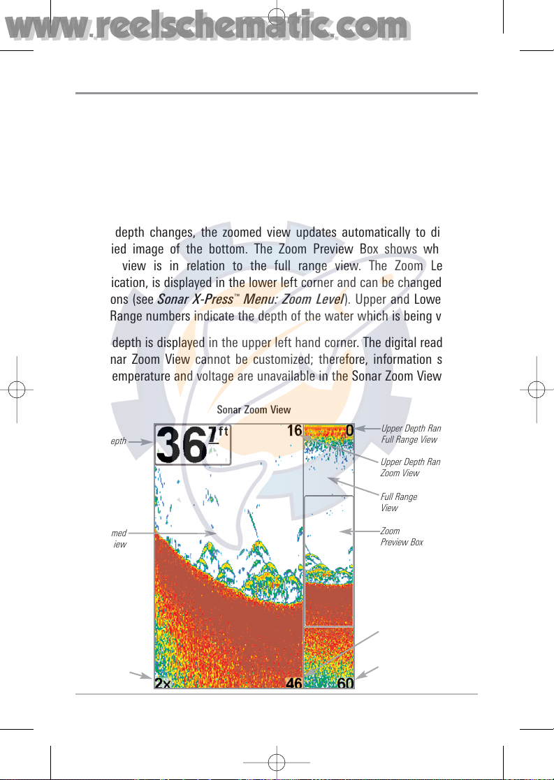
Sonar Zoom View
Sonar Zoom View increases the displayed resolution to separate sonar returns
that are very close together, such as those caused by fish suspended close to
the bottom or within structure. In Zoom View, the display is split to show a
narrow slice of the full range view on the right and the zoomed view on the left.
The full range view on the right also contains the Zoom Preview Box that shows
what part of the full range view is shown in zoom view on the left; the Zoom
Preview Box tracks the bottom in the full range view.
As the depth changes, the zoomed view updates automatically to display a
magnified image of the bottom. The Zoom Preview Box shows where the
zoomed view is in relation to the full range view. The Zoom Level, or
magnification, is displayed in the lower left corner and can be changed to suit
conditions (see Sonar X-Press
™
Menu: Zoom Level). Upper and Lower Zoom
Depth Range numbers indicate the depth of the water which is being viewed.
Digital depth is displayed in the upper left hand corner. The digital readouts in
the Sonar Zoom View cannot be customized; therefore, information such as
water temperature and voltage are unavailable in the Sonar Zoom View.
Sonar Zoom View
Upper Depth Range,
Zoom View
Upper Depth Range,
Full Range View
Full Range
View
Zoom
Preview Box
Lower Depth Range,
Full Range View
Zoomed
View
Zoom
Level
Depth
Lower Depth Range,
Zoom View
531528-1_A - 757c_787c2_&_787c2i_Man_Eng.qxp 10/16/2006 10:41 AM Page 27
www.reelschematic.com
www.reelschematic.com
Page 28
19
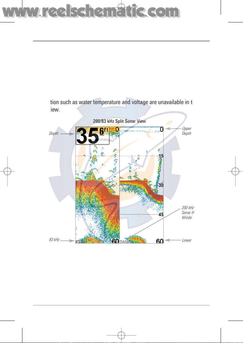
200/83 kHz Split Sonar View
Split Sonar View displays sonar returns from the 83 kHz wide beam on the left
side of the screen and displays sonar returns from the 200 kHz narrow beam on
the right side of the screen. Depth is always displayed in the upper left hand
corner. You can use the Split Sonar View to make side by side comparisons
between the sonar returns from the 83 kHz wide beam and the 200 kHz narrow
beam.
The digital readouts in the Split Sonar View cannot be customized; therefore,
information such as water temperature and voltage are unavailable in the Split
Sonar View.
200/83 kHz Split Sonar View
Depth
83 kHz
Sonar History
Window
200 kHz
Sonar History
Window
Upper
Depth Range
Lower
Depth Range
531528-1_A - 757c_787c2_&_787c2i_Man_Eng.qxp 10/16/2006 10:41 AM Page 28
www.reelschematic.com
www.reelschematic.com
Page 29
20
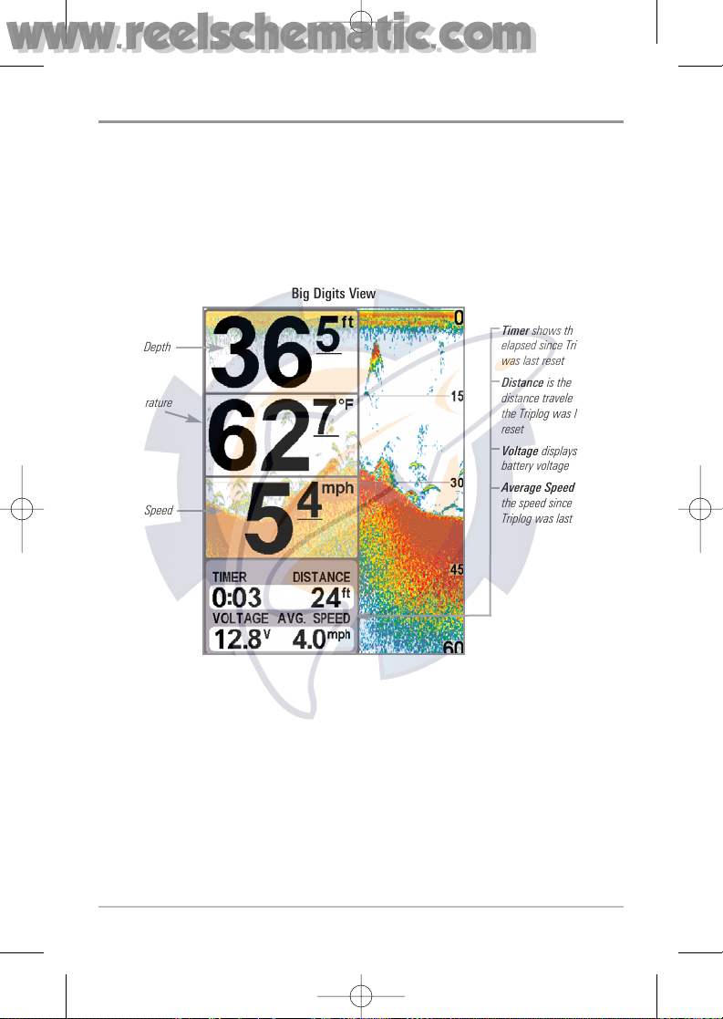
Big Digits View
Big Digits View provides digital data in a large, easy-to-see format. Depth is
always displayed. Readouts for temperature, speed and Triplog information are
displayed automatically if the appropriate accessory is connected to the
system. The Triplog shows distance traveled, average speed, and time elapsed
since the Triplog was last reset. The digital readouts in the Big Digits View
cannot be customized.
Big Digits View
Depth
Temperature
Speed
Timer shows the time
elapsed since Triplog
was last reset
Distance is the
distance traveled since
the Triplog was last
reset
Voltage displays the
battery voltage
Average Speed shows
the speed since the
Triplog was last reset
531528-1_A - 757c_787c2_&_787c2i_Man_Eng.qxp 10/16/2006 10:41 AM Page 29
www.reelschematic.com
www.reelschematic.com
Page 30
21
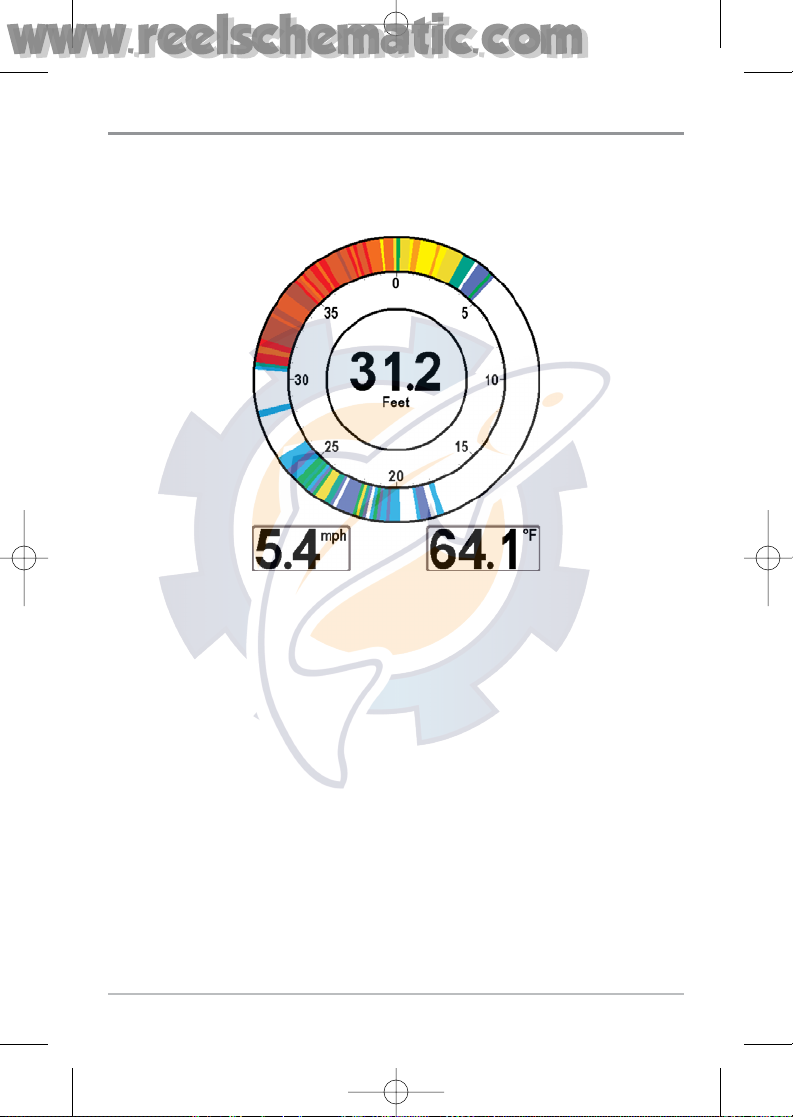
Circular Flasher View
Circular Flasher View displays Real Time Sonar (RTS®) data in the traditional
flasher format. Depth and temperature are always displayed. The digital
readouts in the Circular Flasher View cannot be customized.
531528-1_A - 757c_787c2_&_787c2i_Man_Eng.qxp 10/16/2006 10:41 AM Page 30
www.reelschematic.com
www.reelschematic.com
Page 31

22
Snapshot and Recording View
Snapshot and Recording View displays and allows you to view both screen
snapshot thumbnails and recording icons captured to an optional-purchase
MMC/SD card installed in your unit. In addition, when you are in the Snapshot
and Recording View, Start Recording, Stop Recording, Delete Image, Delete All
Images, Delete Recording, Delete All Recordings, Pings Per Second, Playback
Speed and Stop Playback are added to the X-Press™ menu.
The Snapshot and Recording View displays up to three screen snapshot
thumbnails or recording icons on the screen at a time; you may have to scroll
using the 4-WAY Cursor keys to see the whole list of thumbnails and/or icons
in this view. The selected thumbnail or icon will be highlighted with arrows.
NOTE: The speed of the screen capture or of the recording depends on the type of card you
use; in general, SD cards capture the screen faster than MMC cards do.
Snapshot and Recording View
Amount of
space used for
this recording
Recording
mode icons
Information box
Amount of
recording left
to play
Amount of
recording that
has been played
Snapshot
thumbnail
Recording icon
Unavailable icon
531528-1_A - 757c_787c2_&_787c2i_Man_Eng.qxp 10/16/2006 10:41 AM Page 31
www.reelschematic.com
www.reelschematic.com
Page 32

23
NOTE: For snapshots and recordings, the indicator bar has several states: during recording,
the amount of space remaining on the MMC/SD card is indicated on the status bar. During
playback, the amount of time/memory remaining to play is indicated on the status bar.
When a snapshot thumbnail is highlighted, the amount of room remaining on the MMC/SD
card is indicated.
Screen Snapshot: When Screen Snapshot is enabled (from the Accessories
menu tab), pressing the MARK key creates a saved screen capture (when you
have an optional-purchase MMC/SD card installed). Once you have created a
screen capture, a screen capture thumbnail is added to the Snapshot and
Recording View, and is available to view at a later date. See the full-sized image
by highlighting a thumbnail (using the Up or Down 4-Way Cursor keys), then
using the Right 4-Way Cursor key to view the full image. A border around the
full-size screen snapshot indicates that it is just a screen snapshot, not a “live”
view. You can delete the selected image, or all images, by selecting a thumbnail
and using Delete Image, or using Delete All Images from the Snapshot and
Recording X-Press™ menu.
W
orking with screen snapshots is a four-step process:
1. Enabling Screen Snapshot from the Accessories Menu.
2. Making a Screen Snapshot using the MARK key.
3. Viewing a Screen Snapshot using the Snapshot and Recording View.
4. Deleting a Screen Snapshot using the Snapshot and Recording
X-Press™ menu.
For more information, see Accessories Menu Tab: Using Screen Snapshot and
Snapshot and Recording X-Press™ Menu.
When you start a screen snapshot, you will see a message that a waypoint has
been created at the point where your cursor is on the screen, and the screen
will freeze while the snapshot is being saved to the MMC/SD card. A status
dialog box will appear that shows the progress of the save as a percentage, and
that displays the numbered file name assigned to the .BMP file that is being
created. Snapshot filenames begin with the letter "S". For more information,
see Accessories Menu Tab: Using Screen Snapshot procedure and Snapshot
and Recording X-Press™ Menu.
531528-1_A - 757c_787c2_&_787c2i_Man_Eng.qxp 10/16/2006 10:41 AM Page 32
www.reelschematic.com
www.reelschematic.com
Page 33

24
Recording and Playback: From the Snapshot and Recording View, you can use
the X-Press™ menu to start and stop recording, and to change the pings per
second (which alters the detail level of the recording). Once you are recording
already, playing back a recording and screen snapshot viewing are not allowed,
and the only Sonar Recording menu choices available in the X-Press™ menu are
Stop Recording and Pings Per Second. Use the 4-Way Cursor keys from the
Snapshot and Recording View to start playback of a specific recording icon. You
can then cycle through all the views using the VIEW key to see what those views
looked like during the recorded time period. You can also use the X-Press™
menu to change playback speed, stop playback, and delete recording icons.
W
orking with sonar recordings is a six-step process:
1. Displaying the Snapshot and Recording View.
2. Starting a sonar recording using the Snapshot and Recording
X-Press™ menu.
3. Changing the maximum ping rate for the recording using the Snapshot
and Recording X-Press™ menu (optional).
4. Stopping a recording using the Snapshot and Recording X-Press™ menu.
5. Playing back a recording, using the Snapshot and Recording View and
the 4-Way Cursor keys, and changing the playback speed using the
Snapshot and Recording X-Press™ menu.
6. Deleting a recording using the Snapshot and Recording X-Press™ menu.
For more information, see Snapshot and Recording X-Press™ Menu.
When you start a sonar recording, you will see a message that a waypoint has
been created at your current location. During recording, playing back a
recording and screen snapshot viewing are not allowed. An information box
displays a variety of information including the numbered file name assigned to
the .SON file that is being created. The slider bar at the bottom of the screen
shows the progress of the recording as well as how much space is remaining
on the MMC/SD card.
NOTE: The waypoints that are created by a recording have the same name as the file and use
a custom waypoint icon. Recording filenames begin with the letter "R".
For more information, see Snapshot and Recording X-Press™ Menu.
531528-1_A - 757c_787c2_&_787c2i_Man_Eng.qxp 10/16/2006 10:41 AM Page 33
www.reelschematic.com
www.reelschematic.com
Page 34

25
Highlighting a recording: You can scroll through the whole list of recording
icons available in the Snapshot and Recording View using the 4-WAY Cursor
keys. The highlighted icon will be surrounded by arrows, and a green play
triangle will appear to its right.
Playing back a recording: Highlight a recording icon (using the Up or Down
4-Way Cursor keys), then use the Right 4-Way Cursor key to start playback.
During playback, all active navigation is cancelled, all other thumbnails and
icons will disappear, and a "Playback" message box similar to the Simulation
message will be displayed periodically. When playback begins, the view is
automatically switched to the primary Sonar View for your model, and no live
sonar data will be displayed; only recorded sonar and GPS data will be shown,
and the Snapshot and Recording View will display the playback status. You can
change the speed, skip to the beginning or end of playback, and even reverse
playback, using the Playback Speed X-Press™ menu item, and stop the
playback using the Stop Playback X-Press™ menu item; these items are added
to the X-Press™ menus in all views during playback. In the Snapshot and
Recording Slider Bar
Recording
Indicator
Amount of
space and time
used by this
recording
Name of recording
Time and Date
recording was
started
Position where
recording was
started
Current Ping Rate
Average Ping Rate
Amount of space
remaining on card
Amount remaining
on card
Total amount of
space on card
531528-1_A - 757c_787c2_&_787c2i_Man_Eng.qxp 10/16/2006 10:41 AM Page 34
www.reelschematic.com
www.reelschematic.com
Page 35

26
Recording View only, playback speed can also be changed using the Left and
Right 4-Way Cursor keys. Playback is paused when the sonar cursor is active
and resumes playing when the cursor is removed. Playback is automatically
paused when the end of the recording is reached.
NOTE: Sonar chart speed is increased during Fast Forward and reversed during Rewind. This
may reduce the quality of the sonar image, since at higher speeds, not every sonar return can
be processed and displayed.
NOTE: Navigation is not affected by the Sonar Recording feature, but any active navigation is
cancelled when playback begins or ends.
You can delete the highlighted recording, or all recordings, using Delete Recording
or Delete All Recordings from the Snapshot and Recording X-Press™ menu.
Recording Playback
Amount of time
already played
Name of recording
Time and Date
recording started
Position when
recording started
Current playback
ping rate
Average ping rate
Amount of time
remaining to play
Playback speed
icons
Amount of time
remaining to play
Overall length of
recording
531528-1_A - 757c_787c2_&_787c2i_Man_Eng.qxp 10/16/2006 10:41 AM Page 35
www.reelschematic.com
www.reelschematic.com
Page 36

27
Side Beam View
(with optional-purchase QuadraBeam PLUS™ transducer)
Side Beam View is only available if you have connected an optional-purchase
QuadraBeam™ transducer accessory and when Transducer Select is set to
QuadraBeam (see Sonar Menu Tab: Transducer Select). The QuadraBeam
PLUS™ transducer requires a separate purchase. This view shows sonar
information from both the left and right 455 kHz beams and the 200 kHz downlooking beam in one view. You can customize the way the sonar data is
displayed in the Side Beam View to suit your personal preferences. Depending
on the layout selected from the Quad Layout Sonar X-Press™ menu (only
available on the Sonar X-Press™ menu when in Side Beam View), the display
will represent the same sonar data in one of the following three layouts:
Default, Classic, and Slanted.
Default layout: The top portion of the display presents a historical log of sonar
returns from the 200 kHz down-looking sonar beam. New information in the
down beam panel scrolls from right to left. The bottom portion of the display
presents a historical log of sonar returns from the 455 kHz right- and leftlooking sonar beams. New information in the side beam panels scrolls from the
center out.
Side Beam View, Default Layout
Depth
Temperature
Left Side 455
kHz Sonar
History Window
Right Side
455 kHz
Sonar
History
Window
200 kHz
Sonar
History
Window
Water Surface Line
for 455 kHz
Sonar History
Windows
531528-1_A - 757c_787c2_&_787c2i_Man_Eng.qxp 10/16/2006 10:42 AM Page 36
www.reelschematic.com
www.reelschematic.com
Page 37

28
Classic layout: The top portion of the display presents a historical log of sonar
returns from the 200 kHz down-looking sonar beam. New information in the
down beam panel scrolls from right to left. The bottom portion of the display
presents a historical log of sonar returns from the 455 kHz right- and left-looking
sonar beams. New information appears at the top, and scrolls down the display.
Side Beam View, Classic Layout
Depth
Temperature
Left Side 455
kHz Sonar
History Window
Right Side
455 kHz
Sonar
History
Window
200 kHz
Sonar
History
Window
Water Surface Line
for 455 kHz
Sonar History
Windows
531528-1_A - 757c_787c2_&_787c2i_Man_Eng.qxp 10/16/2006 10:42 AM Page 37
www.reelschematic.com
www.reelschematic.com
Page 38

29
Slanted layout: This layout presents the two 455 kHz side sonar beams and the
200 kHz down-looking sonar beam as three panels of historical data. This layout
is presented as three slanted panels. New information appears on the right,
and scrolls to the left.
In all of these layouts, the sonar information from the side-looking beams
reveals bottom contour, structure and fish similar to the down-looking beam,
but the area covered is to the left and right of the area shown in the downlooking portion, so you actually see more of the bottom. The distance covered
by the right and left beams is based on the depth setting for the down-looking
beam, up to a maximum of 160 feet.
Side Beam View, Slanted Layout
Depth
Left Side
455 kHz Sonar
History Window
200 kHz Sonar
HistoryWindow
Right Side
455 kHz Sonar
History Window
531528-1_A - 757c_787c2_&_787c2i_Man_Eng.qxp 10/16/2006 10:42 AM Page 38
www.reelschematic.com
www.reelschematic.com
Page 39

30
WideSide® View
(with optional-purchase WideSide® transducer)
WideSide® View is only available if you have connected a WideSide® transducer
accessory and when Transducer Select is set to WideSide® (see Sonar Menu Tab:
Transducer Select). The WideSide® transducer requires a separate purchase. The
WideSide® View displays information from the 455 kHz WideSide® transducer.
Three views are available: Left, Right and Both. The default view is Both.
Information from both the left and right beams are displayed simultaneously. The
depth of the water beneath the boat is always displayed. A bottom contour may
be present while bank fishing or fishing river channels. When fishing in the open
water, a bottom contour will not be present, and only sonar returns from either
debris or fish will be displayed.
WideSide View
Left Side
View
Bank
Contour
Water
Surface Line
Depth
Right Side View
Open Water
(no bottom
contour visible
on-screen)
Temperature
531528-1_A - 757c_787c2_&_787c2i_Man_Eng.qxp 10/16/2006 10:42 AM Page 39
www.reelschematic.com
www.reelschematic.com
Page 40

31
Bird’s Eye View
Bird's Eye View - This view shows a 3-D, perspective view of the track and the
chart’s land contour from a point above and behind the boat (the eye point). As the
boat turns, the eye point moves to follow the boat.
When you press the 4-WAY Cursor key in the Bird’s Eye View, the position of the
eye point will shift. This allows you to move and turn the eye point so that you can
look off to the sides, or even behind the boat. Pressing the RIGHT or LEFT arrow
keys on the 4-WAY Cursor key turns the eye point right or left, while pressing
the UP arrow key moves the eye point forward, and pressing the DOWN arrow
key moves the eye point backward.
Pressing the EXIT key moves the eye point back to its original position behind
and above the boat.
Bird’s Eye View
Depth
Land Contours
Boat Icon
Speed of Boat
Latitude and
Longitude
Position of Boat
Bearing of Boat
with Respect to
True North
531528-1_A - 757c_787c2_&_787c2i_Man_Eng.qxp 10/16/2006 10:42 AM Page 40
www.reelschematic.com
www.reelschematic.com
Page 41

32
Chart View
Chart View - This view shows cartography from the built-in UniMap™ or an
optional MMC map for the area surrounding your current position. The current
track (also known as the position history or breadcrumb trail) showing where
the boat has been, along with saved tracks, waypoints, and the current route
(when navigating), are overlaid on the chart. You can use the 4-WAY Cursor
Control key to shift/pan the chart to another area. You can use the ZOOM (+/-)
keys to zoom in and out. You can use the INFO key to get information on the
chart objects near the cursor.
Chart View without Active Cursor, shown with
Optional-Purchase Navionics® Cartography
Depth
Cartography
Speed Of Boat
Bearing of Boat
with Respect
to True North
Water Surface
Temperature
Map Scale
531528-1_A - 757c_787c2_&_787c2i_Man_Eng.qxp 10/16/2006 10:42 AM Page 41
www.reelschematic.com
www.reelschematic.com
Page 42

33
Chart View with Active Cursor, shown with
Optional-Purchase Navionics® Cartography
Depth
Cartography
Latitude and
Longitude
Position of
Cursor
Bearing of Boat
with Respect
to True North
Distance to
the Cursor
and Bearing
to Cursor
Map Scale
Active Cursor
531528-1_A - 757c_787c2_&_787c2i_Man_Eng.qxp 10/16/2006 10:42 AM Page 42
www.reelschematic.com
www.reelschematic.com
Page 43

34
Combo View
Combo View - This view is displayed as a split screen, with Chart View on the
left and Sonar View on the right side of the screen. The width of the sonar
window can be changed.
Combo View
Depth
Cartography
Sonar Window
Bearing of Boat
with Respect to
True North
Water
Surface
Temperature
Speed of Boat
Map
Scale
531528-1_A - 757c_787c2_&_787c2i_Man_Eng.qxp 10/16/2006 10:42 AM Page 43
www.reelschematic.com
www.reelschematic.com
Page 44

35
View Orientation
Both Chart and Combo views allow you to choose the orientation of the view.
When North-Up orientation is selected, True North is shown at the top of the
display. In other words, objects located to the north of the boat are drawn above
the boat. When Course-Up orientation is selected, the direction of motion of the
boat is shown at the top of the display. In other words, objects ahead of the boat
are drawn above the boat. In both orientations, the view pans automatically, so
that the boat is always centered on the display. When the boat is stationary, it
is drawn as a circle. When the boat is in motion, it takes on a boat shape,
pointed in the direction of motion (always Up in the Course-Up orientation).
Viewing Cartography
In the Chart or Combo Views there are several cartography-related functions
that you can access using various keys.
Panning: Use the 4-WAY Cursor keys
to move the chart around on the
display in the direction of the key
being pressed. When you do this, a
bull's eye cursor is drawn at the
center of the screen and is linked to
the boat by a gray line, even if the
boat is off the screen. At the same
time, the temperature and speed
boxes in the lower left corner are
replaced with the distance and
bearing from the boat to the cursor
position and the latitude/longitude
coordinates of the cursor.
Zooming: Use the Plus (+) key to
Zoom In and the Minus (-) key to
Zoom Out showing the cartography at
different scales. The scale is indicated
on the left side of the display. If you zoom in beyond the available chart data,
the display will go into Overzoom mode whereby the last available chart data is
Chart View with Cursor Present, shown with
Optional-Purchase Navionics® Cartography
531528-1_A - 757c_787c2_&_787c2i_Man_Eng.qxp 10/16/2006 10:42 AM Page 44
www.reelschematic.com
www.reelschematic.com
Page 45

36
amplified to reflect the scale selected. If you zoom in so far that no cartography
is available, a lat/long grid will be drawn instead.
Chart Info: Use the INFO key to get detailed information about the chart. If the
cursor is active, you will see information about the chart objects located near
the cursor. If the cursor is not active, the Chart Info menu will appear. You can
select the nearest port, the nearest tide station, or the nearest current station
to see information about any of these objects.
NOTE: The built-in UniMap™does not contain any Port, Tide or Current information. This
information is only available from optional-purchase MMC/SD cards.
Nearest Port: The position and services information for the nearest port to your
present position will be displayed. Press the EXIT key to remove the information
box and the cursor bull’s eye will be centered over the port position. The cursor
information boxes at the bottom of the display will indicate the distance and
bearing to the port from your present position.
Nearest Tide Station: Tide information for the nearest tide station to your
present position will be displayed. This includes the position of the station and
the times of the high and low tides for today’s date. A tide graph is also
displayed showing the rise and fall of the tides for the 24 hour time period
encompassing the date. You can change the date to look at tide information
before or after the date displayed by pressing the LEFT or RIGHT cursor key
respectively. Press the EXIT key to remove the information box and the cursor
bull’s eye will be centered over the tide station position. The cursor information
boxes at the bottom of the display will indicate the distance and bearing to the
tide station from your present position.
Nearest Current Station: Current information for the nearest current station to
your present position will be displayed. This includes the position of the station
and the current changes for today. Two graphs are also presented that show the
time, direction and flow speed of the current changes for the 24 hour time
period of today’s date. You can change the date to look at current information
before or after the date displayed by pressing the LEFT or RIGHT cursor key
respectively. Press the EXIT key to remove the information box and the cursor
bull’s eye will be centered over the current station position. The cursor
information boxes at the bottom of the display will indicate the distance and
bearing to the current station from your present position.
531528-1_A - 757c_787c2_&_787c2i_Man_Eng.qxp 10/16/2006 10:42 AM Page 45
www.reelschematic.com
www.reelschematic.com
Page 46

37
Introduction to Navigation
Use your Fishing System to establish waypoints at areas of interest and to
navigate to those waypoints via a savable route (representing the shortest
intended distance between waypoints). You can also view and save tracks,
which represent the actual path of the boat.
Waypoints, Routes and Tracks
Waypoints are stored positions that allow you to mark areas of interest or
navigation points. Your Fishing System can store up to 3000 waypoints.
Routes link two or more waypoints together to create a path for navigation, and
are used in trip planning. You can link individual waypoints together by using the
GOTO key. A route represents your intended navigation and shows the shortest
path from each waypoint to the next. As you travel a route, staying on the route
line is the most efficient way to get to your destination, although you should
always look out for obstacles not shown on the chart. Your 700 Series™ Fishing
System can store up to 50 routes that can each contain up to 50 waypoints.
Waypoints, Routes and Tracks
Route
Track
Waypoint
Depth
Water
Surface
Temperature
DTG:
Distance to
Go to
Waypoint
Speed of Boat
XTE: Cross
Track Error.
Distance of
Boat from
Route
Bearing of
Boat with
Respect to
True North
BRG: Bearing
to Waypoint
531528-1_A - 757c_787c2_&_787c2i_Man_Eng.qxp 10/16/2006 10:42 AM Page 46
www.reelschematic.com
www.reelschematic.com
Page 47

38
Tracks consist of detailed position history, and are displayed as a breadcrumb
trail of trackpoints. The Current Track shows the position history since the unit
was powered up (maximum of 20,000 trackpoints displayed). You can clear the
Current Track or save it at any time. Your 700 Series™ Fishing System can store
up to 50 saved tracks, each containing 20,000 trackpoints. The current track
represents your actual path so far.
Save, Edit, or Delete a Waypoint
Save your current position as a waypoint: On any view, press the MARK key
to save the current position of the boat as a waypoint.
Save the cursor position as a waypoint: On the Chart or Combo view, use the
Cursor key to designate the position you want to save as a waypoint. Then press
the MARK key to save the marked position as a waypoint.
Save a position from the sonar history: On any Sonar view, use the Cursor key
to point to a feature in the sonar history (also called the Sonar Saver feature).
Press the MARK key to create a waypoint at the location where that sonar
reading was taken. The new waypoint will also record the depth at that
location.
NOTE: When you save a waypoint by any of these methods, a numerical waypoint name
is automatically assigned. You can edit the waypoint information later to give it a different
name and select an icon to represent it (see Waypoint submenu on the Navigation Main
Menu Tab).
Display the Waypoints Submenu: From any view, press the MENU key twice
to display the Main Menu System, then use the RIGHT Cursor key to select the
Navigation tab. Select Waypoints and press the RIGHT Cursor key to display the
Waypoints submenu.
Program a specific position as a waypoint: To create a waypoint that is NOT
your current position, from the Waypoints submenu, select the Create option
and press the RIGHT Cursor key. Use the Cursor keys to program a waypoint
name, latitude, longitude, and icon before selecting Save.
531528-1_A - 757c_787c2_&_787c2i_Man_Eng.qxp 10/16/2006 10:42 AM Page 47
www.reelschematic.com
www.reelschematic.com
Page 48

39
Edit a waypoint: From the Waypoints submenu, select Edit and press the RIGHT
Cursor key to display a list of saved waypoints. Select the waypoint you want to
edit and press the RIGHT Cursor key. Use the 4-WAY Cursor Control key to move
from field to field, and the UP and DOWN Cursor keys to changes values once
you are in a field. In the Waypoint Name, Latitude and Longitude fields, use the
UP and DOWN Cursor keys to change the letter or number. All upper and lower
case letters are available, as well as digits 0-9 and some punctuation characters.
In the Waypoint Icon field, use the UP and DOWN Cursor keys to change the
icon used to represent the waypoint on the Combo and Chart Views. You can exit
these fields with the LEFT and RIGHT Cursor keys or by pressing the EXIT key.
Select Save and press the RIGHT Cursor key to save your changes.
To make it easier to select a waypoint, select Sort By and press the RIGHT or
LEFT Cursor keys to select a sort order:
• Name shows the waypoints alphabetically
• Time shows the most recently-created waypoint first
• Distance shows the closest waypoint first.
Delete a waypoint: From the Waypoints submenu, select Delete and press the
RIGHT Cursor key to display a list of waypoints. Select the waypoint you want
to delete, then press the RIGHT Cursor key. You will be asked to confirm
deletion before the waypoint is actually deleted.
Navigate to a Waypoint or Position
Navigate to the cursor position: From the Chart or Combo view, use the Cursor
key to select a position or waypoint to which you want to navigate. Press the
GOTO key. Navigation will begin immediately.
Navigate to a specified waypoint: Press the GOTO key, then choose the
waypoint to which you would like to navigate from the waypoint list and press
the RIGHT Cursor key to select it.
NOTE: By repeating the previous instructions, you can add more waypoints to create a longer
multi-segment route.
Skipping a waypoint: From the Navigation X-Press™ menu, select Skip Next
Waypoint and press the RIGHT Cursor key. If there is not another waypoint to
skip to, navigation will be cancelled.
531528-1_A - 757c_787c2_&_787c2i_Man_Eng.qxp 10/16/2006 10:42 AM Page 48
www.reelschematic.com
www.reelschematic.com
Page 49

40
Cancel navigation: From the Navigation X-Press™ menu, select Cancel
Navigation and press the RIGHT Cursor key. Canceling navigation removes the
route and any waypoints created using the GOTO key, but does not remove any
saved routes from memory. You will be prompted to save the current route
when you cancel navigation.
Add a Waypoint Target or Trolling Grid
Add or Remove a Waypoint Target: From the Waypoints submenu, select
Target and press the RIGHT Cursor key to display a list of waypoints. Select the
waypoint you want to target. A target consisting of concentric circles centered
on the selected waypoint will appear on all of the navigation views; the target
shows various distance ranges from the targeted waypoint. To remove the
target, choose Remove Target from the Navigation X-Press™ menu.
Chart View with Target
Waypoint
Target
531528-1_A - 757c_787c2_&_787c2i_Man_Eng.qxp 10/16/2006 10:42 AM Page 49
www.reelschematic.com
www.reelschematic.com
Page 50

41
Add or Remove a Trolling Grid: From the Waypoints submenu, select Grid and
press the RIGHT Cursor key to display a list of waypoints. Select the waypoint
to which you want to add the grid. The trolling grid will appear on all of the
navigation views, and can be used as a guide when trolling around a waypoint.
The grid can be rotated to any desired heading using Grid Rotation from the
Navigation Main menu. To remove the trolling grid, choose Remove Grid from
the Navigation X-Press™ menu.
NOTE: Only one waypoint can have either a target or a grid at one time. If you apply a target
or a grid to a new waypoint, the original waypoint will lose its target or grid.
NOTE: The spacing of the rings on the waypoint target and the spacing of the grid lines on
the trolling grid is the same as the length of the scale bar on the left edge of the display.
Zooming in or out will decrease or increase the spacing, respectively.
Chart View with Grid
Waypoint
Trolling
Grid
531528-1_A - 757c_787c2_&_787c2i_Man_Eng.qxp 10/16/2006 10:42 AM Page 50
www.reelschematic.com
www.reelschematic.com
Page 51

42
Save, Edit or Delete a Route
Save the current route: While you are navigating, the current route can be
saved. From the Navigation X-Press
™
menu, select Save Current Route and
press the RIGHT Cursor key. Navigation will continue.
Display the Routes submenu: From any view, press the MENU key twice to
display the Main Menu System, then use the RIGHT Cursor key to select the
Navigation tab. Select Routes and press the RIGHT Cursor key to display the
Routes submenu.
Create a route: From the Routes submenu, select Create and press the RIGHT
Cursor key. A Route Edit screen will be displayed with an empty route. You can
name the route, add waypoints to the route from the list of all waypoints, and
order the waypoints in the route using the Cursor keys.
Edit a saved route: From the Routes submenu, select Edit and press the RIGHT
Cursor key. A Route Edit screen will be displayed. Select the route you wish to
edit and press the RIGHT Cursor key. Re-name the route or change, delete or
re-order the waypoints used in the route.
Delete a saved route: From the Routes submenu, select Delete and press the
RIGHT Cursor key. Select the route you wish to delete and press the RIGHT
Cursor key. You will be asked to confirm your choice by pressing the RIGHT
Cursor key again before the route is deleted.
Travel a saved route: From the Routes submenu, select Travel and press the RIGHT
Cursor key. A list of saved routes will appear. Select the route you wish to travel
and press the RIGHT Cursor key to make this route the current route and begin
navigation. You may also travel the route in either forward or reverse order.
Route Info: From the Routes submenu, select Info and press the RIGHT Cursor
key. A list of saved routes will appear. Select the route for which you want
information, and press the RIGHT Cursor key. The list of waypoints in the route
will be shown, with the distance and bearing from each waypoint to the next,
as well as the distance and bearing from the current position to the first
waypoint in the route.
531528-1_A - 757c_787c2_&_787c2i_Man_Eng.qxp 10/16/2006 10:42 AM Page 51
www.reelschematic.com
www.reelschematic.com
Page 52

43
Save or Clear a Current Track
Save the current track: From the Navigation X-Press™ menu, select Save
Current Track and press the RIGHT Cursor key. The track will remain on the
display, but will change from black to gray. To remove the track completely from
the display, see Edit, Delete or Hide Saved Tracks.
NOTE: When you save a track, a name is automatically assigned. The track name consists of
a date/time stamp, but can be re-named later (see Edit a Saved Track).
Clear the current track: From the Navigation X-Press™ menu, select Clear
Current Track and press the RIGHT Cursor key. The track will be removed from
the display and discarded.
Edit, Delete or Hide Saved Tracks
Display the Tracks Submenu: From any view, press the MENU key twice to
display the Main Menu System, then use the RIGHT Cursor key to select the
Navigation tab. Select Tracks and press the RIGHT Cursor key to display the
Tracks submenu.
Edit a saved track: From the Tracks submenu, select Edit and press the RIGHT
Cursor key to display the list of saved tracks. Select the track you want to edit and
press the RIGHT Cursor key. When the Edit Track dialog box appears, use the
Cursor keys to move between fields. In the Track Name field, the UP and DOWN
Cursor keys change the letter or number. All upper and lower case letters are
available, as well as digits 0-9 and some punctuation characters. You can exit the
Track Name field with the LEFT and RIGHT Cursor keys or by pressing the EXIT key.
Select Save and press the RIGHT Cursor key to save your changes.
Delete a saved track: From the Tracks submenu, select Delete and press the
RIGHT Cursor key to display the list of saved tracks. Select the track you want
to delete and press the RIGHT Cursor key. You will be asked to confirm deletion
before the track is actually deleted.
Hide or display a saved track: From the Tracks submenu, select Visibility and
press the RIGHT Cursor key to display the list of saved tracks. Select the track
you want to hide or display and use the Cursor keys to select Hidden or Visible.
Press the EXIT key to return to the Tracks submenu.
531528-1_A - 757c_787c2_&_787c2i_Man_Eng.qxp 10/16/2006 10:42 AM Page 52
www.reelschematic.com
www.reelschematic.com
Page 53

44
Man Overboard (MOB) Navigation
As soon as you know that you have a man overboard, you should activate MOB
navigation to maximize chances for a successful rescue. MOB navigation
allows you create an MOB waypoint to locate the point at which your man went
overboard, and the relation of the boat to that point. When MOB is activated,
an MOB waypoint, which is a permanent, sharable waypoint with a large,
distinctive icon, is created at the boat's current position (regardless of whether
the chart cursor is active or not). Any current navigation will be cancelled and
the current route discarded without user notification, and MOB navigation will
begin immediately. A line will be drawn from the boat's current position to the
MOB waypoint, and the MOB waypoint will be targeted. The view is switched
to the Chart View automatically when MOB is activated, and an additional info
box that shows the lat/lon position of the MOB waypoint and the elapsed time
since MOB was activated is added to the Chart View.
It is not possible to re-activate MOB or modify the current route without first
canceling MOB navigation.. The Off Course trigger is also disabled and the Off
Course Alarm circle is not drawn. Any press of the GOTO key, or selection of a
GOTO menu item, will cause an error beep and a short message will be
displayed to the user that will disappear after 2 seconds.
Activate MOB navigation: Press and hold the GOTO key for more than 1.5
seconds to activate the Man Overboard (MOB) function.
Cancel MOB navigation: From the Navigation X-Press™ menu, select Cancel
MOB and press the RIGHT Cursor key. Canceling MOB navigation removes the
route and any waypoints created using the GOTO key, but does not remove any
saved routes from memory.
531528-1_A - 757c_787c2_&_787c2i_Man_Eng.qxp 10/16/2006 10:42 AM Page 53
www.reelschematic.com
www.reelschematic.com
Page 54

45
MOB Navigation
Elapsed time
since MOB
was activated
Boat's current
position
Target
surrounding
MOB waypoint
MOB waypoint
Position where
man fell
overboard
531528-1_A - 757c_787c2_&_787c2i_Man_Eng.qxp 10/16/2006 10:42 AM Page 54
www.reelschematic.com
www.reelschematic.com
Page 55

46
Key Functions
Your Fishing System user interface consists of a set of easy-to-use keys that
work with various on-screen views and menus to give you flexibility and control
over your fishing experience.
POWER/LIGHT Key
The POWER/LIGHT key is used to turn the Fishing System on and
off, and also to adjust the backlight and contrast of the display.
Press the POWER/LIGHT key to turn the unit on. The Title screen
is then displayed until the Fishing System begins sonar operation.
To adjust the backlight, or to adjust the display
background color, press the POWER/LIGHT key
to access the Light and Background menu. Use
the 4-WAY Cursor key to select Light or
Background and then use the LEFT or RIGHT
Cursor key to change the settings. Press EXIT to
exit the Light and Background menu.
Press and hold the POWER/LIGHT key for 3 seconds to turn the unit off. A
message will appear telling you how many seconds there are until shutdown
occurs. Your Fishing System should always be turned off using the
POWER/LIGHT key. This will ensure that shutdown occurs properly and any
menu settings will be saved.
VIEW Key
The VIEW key is used to cycle through all available views. Press
the VIEW key to advance to the next view. Repeatedly pressing
VIEW cycles through all views available. Views can be hidden
to optimize the system to your fishing requirements (see
Views Menu Tab).
531528-1_A - 757c_787c2_&_787c2i_Man_Eng.qxp 10/16/2006 10:42 AM Page 55
www.reelschematic.com
www.reelschematic.com
Page 56

47
INFO Key
Info - Press the INFO key while in Bird's Eye, Chart or Combo
View to display information about objects that are nearest to an
active cursor.
If the cursor is not active, the following menu
will be displayed. Use the 4-WAY Cursor key to
select Nearest Port, Nearest Tide Station or
Nearest Current Station, then use the RIGHT
Cursor key to display the requested information.
NOTE: The built-in UniMap™ does not contain Port, Tide
or Current information. This information is only available
from optional purchase MMC/SD cards.
MENU Key
The MENU key is used to access the menu system.
Start-Up Options Menu - Press the MENU key during the power up sequence
to view the Start-Up Options menu.
X-Press™ Menu - Press the MENU key once for the X-Press™ Menu. The X-
Press™ menu allows you to access frequently-used settings without having to
navigate through the whole menu system. When the X-Press™ menu is
displayed, you can use the UP or DOWN Cursor keys to move to a particular
menu choice. As soon as you alter a parameter (using the RIGHT or LEFT Cursor
keys) the X-Press™ menu will collapse temporarily, and the screen will update
if it is affected by your menu setting change, allowing you to see the effects of
your action immediately. Reactivate the X-Press™ Menu by using the UP or
DOWN Cursor keys.
Main Menu - Press the MENU key twice for the tabbed Main Menu System.
The Main Menu System is organized under tabbed headings to help you find a
specific menu item quickly: Alarms, Sonar, Navigation, Chart, Setup, Views and
Accessories tabs are part of your tabbed Main Menu System. Use the LEFT or
RIGHT 4-WAY Cursor Control key to select a tab; then use the DOWN or UP key
to select the menu item, and the LEFT or RIGHT key to alter a menu setting.
531528-1_A - 757c_787c2_&_787c2i_Man_Eng.qxp 10/16/2006 10:42 AM Page 56
www.reelschematic.com
www.reelschematic.com
Page 57

48
4-WAY Cursor Control Key
The 4-Way Cursor Control Key has multiple functions, depending
on the situation:
• Use the DOWN or UP arrow keys to select a menu choice from the menu
list, then use the LEFT or RIGHT arrow keys to change a menu setting.
NOTE: Menu choices are implemented and saved immediately - no further action is required.
• In all Sonar views but the Big Digits view, pressing any 4-WAY Cursor
Control key will activate Freeze Frame and will then allow you to
position the cursor on the display.
• In the Snapshot and Recording View, highlighting a recording icon and
pressing the Right 4-WAY Cursor Control key starts recording playback,
and the Right and Left keys are used to control the speed of playback.
MARK Key
Press the MARK key while in any view to mark the position of a
waypoint, either at the current boat location, or, if the Cursor is
active, at the current Cursor location.
The MARK key only functions if you have the GPS receiver connected, or if you
have enabled Screen Snapshot from the Accessories menu tab. If you have
enabled the Screen Snapshot feature, pressing the MARK key still creates a
waypoint, but it also captures the screen image to the optional-purchase
MMC/SD card.
NOTE: You must have an optional-purchase MMC/SD card installed for the screen snapshot
feature to work.
Navigation is not affected by the Screen Snapshot feature. Also, if Screen
Snapshot is enabled but there is no GPS receiver connected, pressing the
MARK key will capture the screen image and display an error saying that a GPS
position fix is required to create a waypoint.
531528-1_A - 757c_787c2_&_787c2i_Man_Eng.qxp 10/16/2006 10:42 AM Page 57
www.reelschematic.com
www.reelschematic.com
Page 58

49
GOTO Key
The GOTO Key has multiple functions, depending on the situation:
• If the Cursor is active, pressing the GOTO key while in any view creates
a waypoint and starts navigation towards that waypoint. If the Cursor is
not active, pressing the GOTO key displays the list of waypoints, so that
you can select the waypoint towards which you want to navigate.
• If the GOTO key is pressed and held for more than 1.5 seconds, the Man
Overboard (MOB) function is activated. When MOB is activated, an
MOB waypoint, which is a permanent, sharable waypoint with a large,
distinctive icon, is created at the boat's current position (regardless of
whether the chart cursor is active or not). Any current navigation will be
cancelled and the current route discarded without user notification, and
MOB navigation begins immediately. The view is switched to the Chart
View automatically when MOB is activated, and it is not possible to
activate MOB or modify the current route without first canceling MOB
navigation. Any press of the GOTO key, or selection of a GOTO menu
item, will cause an error beep and a short message will be displayed to
the user that will disappear after 2 seconds.
ZOOM (+/-) Key
Press the - or + ZOOM keys while in any of the Navigation
Views or the Sonar Zoom View to change the scale of the
view to appear closer or farther away.
531528-1_A - 757c_787c2_&_787c2i_Man_Eng.qxp 10/16/2006 10:42 AM Page 58
www.reelschematic.com
www.reelschematic.com
Page 59

50
EXIT Key
The EXIT key has multiple functions, depending on the situation:
• If an alarm is sounding, pressing EXIT will cancel the alarm.
• If a menu tab is selected, pressing EXIT will exit the menu mode and
return to the view.
• If a menu is active, pressing EXIT will return to the previous level in the
menu system.
• Pressing EXIT will cycle through the available views in reverse order.
• If Freeze Frame is active, pressing EXIT will return to a scrolling display.
• If the Cursor is active, pressing EXIT will remove the cursor from the display.
531528-1_A - 757c_787c2_&_787c2i_Man_Eng.qxp 10/16/2006 10:42 AM Page 59
www.reelschematic.com
www.reelschematic.com
Page 60

51
Accessory Bus
Use the Accessory Bus to expand the functionality of your Fishing System.
Accessories plug directly into the Fishing System, enabling Advanced features
such as WeatherSense® and the SmartCast® Wireless Sonar Link. Additional
tabs and menu choices will be added to the menu system automatically when
an accessory is plugged into the unit. In addition, multiple accessories can be
attached simultaneously. See Accessories Menu Tab and 700 Series™
Fishing System Accessories in this manual, as well as your accessory's
Operations Manual for additional details.
NOTE: Accessories to enable WeatherSense® and the SmartCast® Wireless Sonar Link require
separate purchases. You can visit our website at www.humminbird.com or contact our
Customer Resource Center at 1-800-633-1468 for additional details.
531528-1_A - 757c_787c2_&_787c2i_Man_Eng.qxp 10/16/2006 10:42 AM Page 60
www.reelschematic.com
www.reelschematic.com
Page 61

52
Powering Up the Unit
Turn on your Fishing System by pressing the POWER/LIGHT key. The Title
screen is displayed until the Fishing System begins operation. Your Fishing
System will begin Normal or Simulator operation, depending on the presence
or absence of a transducer.
787c2Title Screen
787c
2
531528-1_A - 757c_787c2_&_787c2i_Man_Eng.qxp 10/16/2006 10:42 AM Page 61
www.reelschematic.com
www.reelschematic.com
Page 62

53
The Menu System
The menu system is divided into easy-to-use menu modules. The main
components of the menu system are:
Start-Up Options Menu - Press the MENU key during the power up sequence
to view the Start-Up Options menu.
X-Press™Menu - The X-Press™Menu allows you
to access the settings that are changed frequently
without having to navigate through the whole
menu system. Press the MENU key once to
display the X-Press™Menu. When you select a
menu item from the X-Press™Menu, the menu
will collapse, leaving only the menu choice on the
screen. Use the UP or DOWN Cursor keys to
reactivate the X-Press™Menu.
NOTE: The X-Press™ Menu choices will vary depending on which view is active when you
press the MENU key, as well as whether you are in Normal or Advanced User Mode. Either
the Sonar, Navigation, or Screen Snapshot X-Press™ Menu will appear, depending on the
view you are in.
Main Menu Tabs - Less frequently-adjusted
menus are grouped into the Main Menu
System. The Main Menu system is organized
under the following tab headings to help you
find a specific menu item quickly: Alarms,
Sonar, Navigation, Chart, Setup, Views and
Accessories.
Press the MENU key twice for the Main Menu,
then use the 4-WAY Cursor LEFT or RIGHT key to
select a tab, and use the DOWN or UP key to
select a specific menu item under that tab, then
use the LEFT or RIGHT keys again to change a
menu setting. Press the EXIT key to move quickly
to the top of the tab. A down arrow at the bottom
of a menu means that you can scroll to additional menu choices using the DOWN
Cursor key. A right or left arrow on a menu choice means that you can use the
RIGHT or LEFT Cursor keys to make changes or to see more information.
NOTE: The Main Menu choices will vary depending on whether you are in Normal or
Advanced User Mode.
Main Menu System
Normal User Mode
X-Press™Menu
531528-1_A - 757c_787c2_&_787c2i_Man_Eng.qxp 10/16/2006 10:42 AM Page 62
www.reelschematic.com
www.reelschematic.com
Page 63

54
User Mode (Normal or Advanced) - An Advanced Mode is provided for users who
desire the highest level of control over the Fishing System and Normal Mode for
users who desire greater simplicity and fewer menu choices. Additional Advanced
menu choices will be displayed throughout the menu system when you navigate to
specific menus while in Advanced Mode. Any changes made while in Advanced
Mode will remain in effect after you switch back to Normal Mode. See Setup Menu
Tab: User Mode for specific instructions on changing to Advanced User Mode.
Total Screen Update - when you change any menu settings that affect the
Sonar View, the view will update immediately (i.e. you don’t have to exit the
menu to apply the change to the screen).
Sonar Tab, Normal Mode
Sonar Tab, Advanced Mode
531528-1_A - 757c_787c2_&_787c2i_Man_Eng.qxp 10/16/2006 10:42 AM Page 63
www.reelschematic.com
www.reelschematic.com
Page 64

55
Start-Up Options Menu
Press the MENU key when the Title screen is displayed to access the Start-Up
Options menu.
Use the UP or DOWN 4-WAY Cursor keys to position the cursor, then the RIGHT
Cursor key to select one of the following choices. If you wait too long, the
system will default to whichever menu mode happens to be highlighted:
• Normal
• Simulator
• System Status
• PC Connect (use with PC Connect Cable).
See the following paragraphs for more information about each of these choices.
Normal Operation
Use Normal Operation for on the water operation with a transducer connected.
In addition, your Fishing System uses advanced transducer detection methods
to determine if a transducer is connected. If a functioning transducer is
connected, Normal operation will be selected automatically at power up and
your Fishing System can be used on the water.
Exit Normal operation by powering your Fishing System off.
531528-1_A - 757c_787c2_&_787c2i_Man_Eng.qxp 10/16/2006 10:42 AM Page 64
www.reelschematic.com
www.reelschematic.com
Page 65

56
Simulator
Use the Simulator to learn how to use your Fishing System before taking your
boat on the water. The Simulator is a very powerful tool that simulates on the
water operation, providing a randomly-updated display. We recommend going
through this manual while using the Simulator, since all of the menus function
and affect the display the way they actually do when in Normal operation.
NOTE: To get the full benefit of the Simulator, it is important to select Simulator manually
from the Start-Up Options menu as opposed to letting the Fishing System enter Simulator
automatically (as it will if a transducer is not connected and you do nothing during power up).
Manually selecting Simulator from the Start-Up Options menu allows you to pre-configure
your Fishing System for on the water operation. Any menu changes you make will be saved
for later use.
A message will appear on the display periodically to remind you that you are
using the Simulator.
Exit the Simulator by powering your Fishing System off.
Simulator (shown with optional-purchase
Weathersense® attached)
531528-1_A - 757c_787c2_&_787c2i_Man_Eng.qxp 10/16/2006 10:42 AM Page 65
www.reelschematic.com
www.reelschematic.com
Page 66

57
System Status
Use System Status to view system connections and to conduct a unit self-test.
The following screens are displayed in turn when you press the VIEW button
when using System Status:
• Self Test
• Accessory Test
• GPS Diagnostic View.
Exit System Status by powering your Fishing System off.
Self Test
Self Test displays results from the internal diagnostic self test, including unit
serial number, Printed Circuit Board (PCB) serial number, software revision,
total hours of operation and the input voltage.
Self Test Screen
531528-1_A - 757c_787c2_&_787c2i_Man_Eng.qxp 10/16/2006 10:42 AM Page 66
www.reelschematic.com
www.reelschematic.com
Page 67

58
Accessory Test
Accessory Test lists the accessories connected to the system.
NOTE: The speed accessory will be detected only if the paddlewheel has moved since your
Fishing System was powered up.
System Status Accessory Test Screen
531528-1_A - 757c_787c2_&_787c2i_Man_Eng.qxp 10/16/2006 10:42 AM Page 67
www.reelschematic.com
www.reelschematic.com
Page 68

59
GPS Diagnostic View
GPS Diagnostic View shows a sky chart and numerical data from the GPS
receiver. The sky chart shows the location of each visible GPS satellite with its
satellite number and a signal strength bar. A dark gray bar indicates that the
satellite is being used to determine your current position. A light orange bar
indicates that the satellite is being monitored, but is not yet being used.
This view also reports the current position, local time and date, and other
numeric information. The current GPS Fix Type is reported as No Fix, 2D Fix, 3D
Fix, or Enhanced. An Enhanced fix has been augmented using information from
WAAS, EGNOS, or MSAS. A 3D or Enhanced Fix is required for navigation.
HDOP (the Horizontal Dilution of Precision) is a GPS system parameter which
depends on the current satellite configuration. HDOP is used to calculate the
Estimated Position Error.
GPS Diagnostic View
Satellite Being
Monitored
Satellite
Being Used
Current Latitude
and Longitude
Sky Chart
531528-1_A - 757c_787c2_&_787c2i_Man_Eng.qxp 10/16/2006 10:42 AM Page 68
www.reelschematic.com
www.reelschematic.com
Page 69

60
PC Connect (with PC Connect cable only)
Use PC Connect to update the software of the Fishing System control head.
This feature requires the use of the PC Connect Cable. Complete instructions
are included with the PC Connect Cable accessory.
NOTE: The PC Connect Cable requires a separate purchase. For more information visit
our website at www.humminbird.com or contact our Customer Resource Center at
1-800-633-1468.
Exit PC Connect mode by powering the Fishing System off.
531528-1_A - 757c_787c2_&_787c2i_Man_Eng.qxp 10/16/2006 10:42 AM Page 69
www.reelschematic.com
www.reelschematic.com
Page 70

61
Sonar X-Press™ Menu
(Sonar views only)
The Sonar X-Press™menu provides access to
the settings most frequently-used. Press the
MENU key once while in any of the Sonar Views
to access the Sonar X-Press
™
menu.
NOTE: Menu choices will vary depending on system
settings such as whether the unit is set for Advanced User
mode or what transducer is currently selected.
NOTE: Quad Layout only appears in Side Beam View with
optional-purchase QuadraBeam PLUS™ transducer.
Sonar X-Press™Menu
531528-1_A - 757c_787c2_&_787c2i_Man_Eng.qxp 10/16/2006 10:42 AM Page 70
www.reelschematic.com
www.reelschematic.com
Page 71

62
Side
(WideSide® transducer: WideSide® view only)
Side sets which transducer beam from the WideSide® Transducer is shown in the
WideSide® View. A WideSide® transducer must be connected to the Fishing
System. The Side menu choice is available when Transducer Select is set to
WideSide® (see Sonar Menu Tab: Transducer Select) and can only be accessed
from the Sonar X-Press
™
menu when you are in WideSide® view.
NOTE: Side requires the purchase of the WideSide® transducer. You can visit our website at
www.humminbird.com to order this accessory online or contact our Customer Resource
Center at 1-800-633-1468.
To adjust the Side:
1. Make sure you are in WideSide® Transducer Mode and that a
WideSide® transducer is connected, then highlight Side on the Sonar
X-Press™ menu.
2. Use the LEFT or RIGHT 4-WAY Cursor Control keys to change the Side
setting. (L [Left], Both, R [Right], Default = Both).
531528-1_A - 757c_787c2_&_787c2i_Man_Eng.qxp 10/16/2006 10:42 AM Page 71
www.reelschematic.com
www.reelschematic.com
Page 72

63
Sensitivity
Sensitivity controls how much detail is shown on
the display and will adjust the sensitivity of all sonar frequencies. Increasing
the sensitivity shows more sonar returns from small baitfish and suspended
debris in the water; however, the display may become too cluttered. When
operating in very clear water or greater depths, increased sensitivity shows
weaker returns that may be of interest. Decreasing the sensitivity eliminates
the clutter from the display that is sometimes present in murky or muddy water.
If Sensitivity is adjusted too low, the display may not show many sonar returns
that could be fish.
NOTE: The Sensitivity setting is a global setting and will adjust the sensitivity of all sonar
frequencies, as compared to specific sensitivity adjustments (such as 83 kHz Sensitivity,
455 kHz Balance or Wideside Sensitivity) which allow you to adjust the level of sensitivity for
one specific beam at a time.
To adjust the Sensitivity:
1. Highlight Sensitivity on the Sonar X-Press™ Menu.
2. Use the LEFT or RIGHT 4-WAY Cursor Control keys to increase or
decrease the Sensitivity setting. (Low = 1, High = 20, Default = 10)
Sensitivity at Low
Sensitivity at Medium
Sensitivity at High
531528-1_A - 757c_787c2_&_787c2i_Man_Eng.qxp 10/16/2006 10:43 AM Page 72
www.reelschematic.com
www.reelschematic.com
Page 73

64
Upper Range
(Advanced: Sonar, Split Sonar, Big Digits and
Circular Flasher Views only)
Upper Range sets the shallowest depth range that will be displayed on the
Sonar, Split Sonar, Big Digits and Circular Flasher views. The Upper Range menu
choice is available when User Mode is set to Advanced (see Setup Menu Tab:
User Mode) and can only be accessed from the Sonar, Split Sonar, Big Digits
and Circular Flasher views. Upper Range is often used with Lower Range.
NOTE: A minimum distance of 10 feet will be maintained between the Upper and Lower
Range regardless of the manual settings entered.
To adjust the Upper Range:
1. Make sure you are in Advanced Mode, then highlight Upper Range on
the Sonar X-Press™ Menu.
2. Use the LEFT or RIGHT 4-WAY Cursor Control keys to increase or
decrease the Upper Range setting. (0 to 1490 feet or 0 to 497 meters
[International Models only], Default = 0)
For example, if you are only interested in the area between 20 and 50 feet deep,
you should set the Upper Depth Range to 20 and the Lower Depth Range to 50.
The Sonar View will then show the 30 foot area between 20 and 50, and will not
show the surface or the bottom (assuming the bottom is deeper than 50 feet), and
will show greater detail for that area between 20 and 50 feet.
531528-1_A - 757c_787c2_&_787c2i_Man_Eng.qxp 10/16/2006 10:43 AM Page 73
www.reelschematic.com
www.reelschematic.com
Page 74

65
Lower Range
Lower Range sets the deepest depth range that
will be displayed. Automatic is the default setting. When in automatic mode,
the lower range will be adjusted by the unit to follow the bottom. Selecting a
specific setting locks the depth range into Manual mode. Use both Upper and
Lower Range together to view a specific depth range manually when looking
for fish or bottom structure. will be displayed in the lower right corner of
the screen when you start manually adjusting the Lower Range to indicate that
you are in Manual mode.
NOTE: A minimum distance of 10 feet will be maintained between the Upper and Lower
Range regardless of the manual settings entered.
T
o adjust the Lower Range:
1. Highlight Lower Range on the Sonar X-Press™ Menu.
2. Use the LEFT or RIGHT 4-WAY Cursor Control keys to increase or
decrease the Lower Range setting. (AUTO, 10 to 1500 feet, 3 to 500
meters [International Models only], Default = AUTO)
For example, if you are fishing in 60 feet of water but are only interested in
the first 30 feet (surface to a depth of 30 feet) you should set the Lower
Depth Range limit to 30. The display will show the 0 to 30 foot range,
allowing you to see a more detailed view than you would see if the display
went all the way to the bottom.
M
531528-1_A - 757c_787c2_&_787c2i_Man_Eng.qxp 10/16/2006 10:43 AM Page 74
www.reelschematic.com
www.reelschematic.com
Page 75

66
Side Beam Range
(WideSide® transducer: WideSide® view only)
Side Beam Range sets the deepest range that will be displayed in the
WideSide® View. The range must be set manually to keep the bottom visible on
the display. If the Side Beam Range is set too deep for current depth conditions
the sonar information will become compressed on the display and valuable
detail will be lost. A WideSide® transducer must be connected to the Fishing
System. Side Beam Range menu choice is available when Transducer Select is
set to WideSide® (see Sonar Menu Tab: Transducer Select) and can only be
accessed from the WideSide® view.
NOTE: The Side Beam Range requires the purchase of the WideSide® transducer. You can visit
our website at www.humminbird.com to order this accessory online or contact our Customer
Resource Center at 1-800-633-1468.
To adjust the Side Beam Range:
1. Make sure you are in WideSide® Transducer Mode, a WideSide®
transducer is connected and that you are in WideSide View, then
highlight Side Beam Range on the Sonar X-Press™ menu.
2. Use the LEFT or RIGHT 4-WAY Cursor Control keys to increase or
decrease the Side Beam Range setting. (6 - 160 feet [2 - 50 meters]
[International Models only], Default = 160 feet [50 meters])
531528-1_A - 757c_787c2_&_787c2i_Man_Eng.qxp 10/16/2006 10:43 AM Page 75
www.reelschematic.com
www.reelschematic.com
Page 76

67
Chart Speed
Chart Speed determines the speed at which the
sonar information moves across the display, and consequently the amount of
detail shown. A faster speed shows more information and is preferred by most
anglers; however, the sonar information moves across the display quickly. A
slower speed keeps the information on the display longer, but the bottom and fish
details become compressed and may be difficult to interpret. Regardless of the
Chart Speed setting, the RTS® Window will update at the maximum rate possible
for the depth conditions. Adjust Chart Speed to your personal preference.
T
o adjust the Chart Speed:
1. Highlight Chart Speed on the Sonar X-Press™ Menu.
2. Use the LEFT or RIGHT 4-Way Cursor Control keys to increase or
decrease the Chart Speed setting. (1-9, Ultra, where 1 = Slow, 9 = Fast,
Ultra = Fastest, Default = 5)
Quad Layout
(with Optional-Purchase QuadraBeam PLUS™
Transducer, Side Beam View only)
Quad Layout selects the method used to represent the sonar information from
the two side-looking beams plus the down-looking beam to be presented on
the Side Beam View, and is only available when an optional-purchase
QuadraBeam PLUS™ transducer is attached and the Side Beam View is active.
Use Quad Layout to change the way the Side Beam View is displayed. See Side
Beam View for more information.
T
o adjust the Quad Layout:
1. Highlight Quad Layout on the Sonar X-Press™ menu.
2. Use the LEFT or RIGHT 4-Way Cursor Control keys to change the Quad
Layout setting for the Side Beam View. (Default, Classic, Slanted,
Default = Default)
531528-1_A - 757c_787c2_&_787c2i_Man_Eng.qxp 10/16/2006 10:43 AM Page 76
www.reelschematic.com
www.reelschematic.com
Page 77

68
Bottom Lock
(Sonar Zoom view only)
Bottom Lock changes the mode of the Zoomed view in the Sonar Zoom View.
Bottom Lock continuously graphs the bottom at a constant point on the display
regardless of changes in depth. This "flattens" out the bottom contour, but is
effective at showing fish on or near the bottom.
T
o turn on Bottom Lock:
1. In the Sonar Zoom View, highlight Bottom Lock on the Sonar X-Press™
Menu.
2. Use the LEFT or RIGHT 4-WAY Cursor Control keys to change the
Bottom Lock setting to on. (Off, On, Default = Off)
Bottom Range
(Sonar Zoom view only when Bottom Lock is On)
Bottom Range allows you to control how much of the water column, measured
up from the bottom, is shown in the Sonar Zoom View. Choose a small value to
see low-lying bottom structure or details of the bottom return. Choose a larger
value to see large structure in deeper water. It is possible to set the Bottom
Range to be greater than the depth. In this case, you may see surface clutter in
a wavy band that mirrors changes in the depth.
T
o adjust the Bottom Range:
1. In the Sonar Zoom View, highlight Bottom Lock on the Sonar X-Press™
Menu.
2. Use the LEFT or RIGHT 4-WAY Cursor Control keys to change the
Bottom Lock setting to on.
3. Once you turn on Bottom Lock, the Bottom Range X-Press™ menu
choice will be displayed. (10 - 60 feet, 2-10 fathoms, or 3-20 meters
[International Models only], Default = 15 feet)
531528-1_A - 757c_787c2_&_787c2i_Man_Eng.qxp 10/16/2006 10:43 AM Page 77
www.reelschematic.com
www.reelschematic.com
Page 78

69
Cancel Navigation
(only when Navigating)
Cancel Navigation discards the current route and exits Navigation Mode. This
menu choice will only appear when you are currently navigating a route. This
will not delete a previously-saved route.
T
o Cancel Navigation:
1. Highlight Cancel Navigation on the Sonar X-Press™ menu.
2. Use the RIGHT 4-WAY Cursor Control key to initiate canceling
navigation.
3. The Confirm dialog box will appear. To cancel navigation, press the
RIGHT Cursor key once more. To avoid canceling navigation, press the
LEFT Cursor key.
531528-1_A - 757c_787c2_&_787c2i_Man_Eng.qxp 10/16/2006 10:43 AM Page 78
www.reelschematic.com
www.reelschematic.com
Page 79

70
Navigation X-Press™ Menu
(Navigation views only)
The Navigation X-Press™ menu provides
access to the settings most frequently used.
Press the MENU key once while in the Bird's Eye
View, the Chart or the Combo View to access
the Navigation X-Press™ menu.
NOTE: Menu choices will vary depending on system
settings, such as whether you are currently navigating.
Navigation X-Press™ Menu
531528-1_A - 757c_787c2_&_787c2i_Man_Eng.qxp 10/16/2006 10:43 AM Page 79
www.reelschematic.com
www.reelschematic.com
Page 80

71
Waypoint [Name]
(Only with an active cursor on a waypoint)
Waypoint [Name] allows you to view the Waypoints submenu for the waypoint
under your cursor.
T
o view the Waypoint [Name] Submenu:
1. Move the cursor onto an existing waypoint and press the MENU key
once, or use Cursor to Waypoint to select a waypoint from a list of
saved waypoints.
2. Highlight Waypoint [Name] on the Navigation
X-Press™ menu.
3. Use the RIGHT 4-Way Cursor Control key to view the Waypoints
submenu, which contains the following menu choices:
T
he Waypoint Submenu contains the following menu choices:
Edit allows you to edit the Name, Position (Latitude and Longitude) and select
the Icon that will be used to represent the waypoint in the Chart and Combo
Views.
Delete allows you to delete a waypoint from the list of saved waypoints.
Target allows you to apply a target to a waypoint selected from the list of
waypoints.
Grid allows you to apply a trolling grid to a waypoint selected from the list of
waypoints.
Waypoint Submenu
531528-1_A - 757c_787c2_&_787c2i_Man_Eng.qxp 10/16/2006 10:43 AM Page 80
www.reelschematic.com
www.reelschematic.com
Page 81

72
Cursor to Waypoint
(Chart or Combo view only)
Cursor to Waypoint allows you to quickly move the cursor to any saved
waypoint, so that you can locate it or edit it.
NOTE: This X-Press™menu item appears only if you have saved waypoints.
To mov
e cursor to a saved waypoint:
1. Highlight Cursor to Waypoint on the Navigation X-Press™ menu.
2. Use the RIGHT 4-WAY Cursor Control key to initiate Cursor to
Waypoint.
3. Use the UP or DOWN 4-WAY Cursor Control key to highlight the
waypoint you wish to move the cursor to, then use the RIGHT 4-WAY
Cusor Control key to select the destination waypoint.
Save Current Track
Save Current Track allows you to save the current
track being displayed. After the current track is saved, a new current track is
started.
T
o Save Current Track:
1. Highlight Save Current Track on the Navigation X-Press™ menu.
2. Use the RIGHT 4-WAY Cursor Control key to initiate saving the current
track.
3. The Confirm dialog box will appear. To save the current track, press the
RIGHT Cursor key once more. To cancel saving the current track, press
the LEFT Cursor key.
531528-1_A - 757c_787c2_&_787c2i_Man_Eng.qxp 10/16/2006 10:43 AM Page 81
www.reelschematic.com
www.reelschematic.com
Page 82

73
Clear Current Track
Clear Current Track allows you to clear the
current track being displayed and start a new track at the present position.
T
o Clear Current Track:
1. Highlight Clear Current Track on the Navigation X-Press™ menu.
2. Use the RIGHT 4-WAY Cursor Control key to initiate clearing the current
track.
3. The Confirm dialog box will appear. To clear the current track, press the
RIGHT Cursor key once more. To cancel clearing the current track, press
the LEFT Cursor key.
Save Current Route
(only when Navigating)
Save Current Route allows you to save the current route being displayed. This
menu choice will only appear when you are currently navigating a route.
T
o Save Curr
ent Route:
1. Highlight Save Current Route on the Navigation X-Press™ menu.
2. Use the RIGHT 4-WAY Cursor Control key to initiate saving the current
route.
3. The Confirm dialog box will appear. To save the current route, press the
RIGHT Cursor key once more. To cancel saving the current route, press
the LEFT Cursor key.
531528-1_A - 757c_787c2_&_787c2i_Man_Eng.qxp 10/16/2006 10:43 AM Page 82
www.reelschematic.com
www.reelschematic.com
Page 83

74
Skip Next Waypoint
(only when Navigating)
Skip Next Waypoint removes the next waypoint from the current route. This
menu choice will only appear when you are currently navigating a route.
T
o Skip Next Waypoint:
1. Highlight Skip Next Waypoint on the Navigation X-Press™ menu.
2. Use the RIGHT 4-WAY Cursor Control key to initiate skipping the next
waypoint.
3. The Confirm dialog box will appear. To skip the next waypoint, press the
RIGHT Cursor key once more. To cancel skipping the next waypoint,
press the LEFT Cursor key.
Cancel Navigation
(only when Navigating)
Cancel Navigation discards the current route and exits Navigation Mode. This
menu choice will only appear when you are currently navigating a route. This
will not delete a previously-saved route.
T
o Cancel Navigation:
1. Highlight Cancel Navigation on the Navigation X-Press™ menu.
2. Use the RIGHT 4-WAY Cursor Control key to initiate canceling
navigation.
3. The Confirm dialog box will appear. To cancel navigation, press the
RIGHT Cursor key once more. To avoid canceling navigation, press the
LEFT Cursor key.
531528-1_A - 757c_787c2_&_787c2i_Man_Eng.qxp 10/16/2006 10:43 AM Page 83
www.reelschematic.com
www.reelschematic.com
Page 84

75
Cancel MOB Navigation
(only when MOB Navigation is activated)
Cancel MOB Navigation removes the Man Overboard (MOB) waypoint and
exits Man Overboard mode. This menu choice will only appear when you are
currently navigating in Man Overboard mode.
T
o Cancel MOB Navigation:
1. Highlight Cancel MOB Navigation on the Navigation X-Press™ menu.
2. Use the RIGHT 4-WAY Cursor Control key to initiate canceling MOB
navigation.
3. The Confirm dialog box will appear. To cancel MOB navigation, press
the RIGHT Cursor key once more. To avoid canceling MOB navigation,
press the LEFT Cursor key.
Remove Target
(only if a Target is Active)
Remove Target removes the waypoint target from the display. This menu choice
will only appear when a target has already been applied to a waypoint.
NOTE: See Add a Waypoint Target or Trolling Grid for more information.
To Remove a Target:
1. Highlight Remove Target on the Navigation X-Press™ menu.
2. Use the RIGHT 4-WAY Cursor Control key to remove the target.
531528-1_A - 757c_787c2_&_787c2i_Man_Eng.qxp 10/16/2006 10:43 AM Page 84
www.reelschematic.com
www.reelschematic.com
Page 85

76
Remove Grid
(only if a Grid is Active)
Remove Grid removes the waypoint grid from the display. This menu choice will
only appear when a grid has already been applied to a waypoint.
NOTE: See Add a Waypoint Target or Trolling Grid for more information.
To Remov
e a Grid:
1. Highlight Remove Grid on the Navigation X-Press™ menu.
2. Use the RIGHT 4-WAY Cursor Control key to remove the grid.
Sonar Window
(Combo view only)
Sonar Window sets the size of the Sonar Window in the Combo View. Sonar
Window can only be accessed from the Combo View.
T
o Set the Size of the Sonar Window in the Combo Vie
w:
1. Highlight Sonar Window on the Navigation X-Press™ menu.
2. Use the LEFT or RIGHT 4-WAY Cursor Control keys to adjust the size of
the sonar window. (Wide, Medium, Narrow, Default = Medium)
531528-1_A - 757c_787c2_&_787c2i_Man_Eng.qxp 10/16/2006 10:43 AM Page 85
www.reelschematic.com
www.reelschematic.com
Page 86

77
Waypoint [Name]
(Most recently-created waypoint)
Waypoint [Name] allows you to view the waypoints submenu for the most
recently created waypoint.
NOTE: You must have pressed the MARK key at least once since you last powered up the
Fishing System for this menu choice to appear.
To view the Waypoint [Name] Submenu:
1. Move the cursor to the desired position and press the MARK key once
to save a waypoint.
2. Highlight Waypoint[Name] on the Navigation X-Press™ menu.
3. Use the RIGHT 4-Way Cursor Control key to view the Waypoints
submenu.
The Waypoint Submenu contains the following menu choices:
Edit allows you to edit the Name, Position (Latitude and Longitude) and select
the Icon that will be used to represent the waypoint in the Chart and Combo
Views.
Delete allows you to delete a waypoint from the list of saved waypoints.
Go To allows you to select a waypoint and start navigation toward that
waypoint, or add that waypoint to the end of the current route.
Target allows you to apply a target to a waypoint selected from the list of
waypoints.
Grid allows you to apply a trolling grid to a waypoint selected from the list of
waypoints.
Waypoint [Name] Submenu
531528-1_A - 757c_787c2_&_787c2i_Man_Eng.qxp 10/16/2006 10:43 AM Page 86
www.reelschematic.com
www.reelschematic.com
Page 87

78
Snapshot and Recording
X-Press™ Menu
(Snapshot and Recording View only)
The Snapshot and Recording X-Press™menu
provides access to the image management and
sonar recording functions. Press the MENU key
once while in the Snapshot and Recording
View to access the Snapshot and Recording
X-Press™ menu.
NOTE: For more information, see Snapshot and
Recording View.
Snapshot and Recording
X-Press™Menu
531528-1_A - 757c_787c2_&_787c2i_Man_Eng.qxp 10/16/2006 10:43 AM Page 87
www.reelschematic.com
www.reelschematic.com
Page 88

79
Start Recording
(optional-purchase MMC/SD Card, Snapshot and
Recording View only)
Start Recording allows you to start sonar recording from the Snapshot and
Recording View. This menu option is only available when you have an optionalpurchase MMC/SD card installed and you are in Snapshot and Recording View.
T
o start sonar recording:
1. Highlight Start Recording on the Snapshot and Recording X-Press™
menu, and press the RIGHT 4-Way Cursor key to start recording.
Stop Recording
(optional-purchase MMC/SD Card only)
Stop Recording allows you to stop sonar recording. This menu option is only
available when you have an optional-purchase MMC/SD card installed.
To stop sonar recording:
1. To stop recording, highlight Stop Recording from any X-Press™ menu.
2. Press the RIGHT 4-Way Cursor key.
531528-1_A - 757c_787c2_&_787c2i_Man_Eng.qxp 10/16/2006 10:43 AM Page 88
www.reelschematic.com
www.reelschematic.com
Page 89

80
Delete Image
(optional-purchase MMC/SD Card, Snapshot and
Recording View only)
Delete Image allows you to delete a single screen capture image from the
Snapshot and Recording View. This menu option is only available when you
have an optional-purchase MMC/SD card installed and you are in Snapshot
and Recording View and you have selected an image thumbnail.
T
o delete an image:
1. On the Screen Snapshot View, use the UP and DOWN 4-Way Cursor
keys to select the image you want to delete.
2. Highlight Delete Image on the Snapshot and Recording X-Press™ menu.
3. Press the RIGHT 4-Way Cursor key to initiate this procedure.
4. A Confirm Dialog box will appear. Select Yes to delete the image or No
to cancel the operation.
Delete All Images
(optional-purchase MMC/SD Card, Snapshot and
Recording View only)
Delete All Images allows you to delete all the images at once from the
Snapshot and Recording View. This menu option is only available when you
have an optional-purchase MMC/SD card installed and you are in Snapshot
and Recording View.
T
o delete all images:
1. From the Snapshot and Recording View, highlight Delete All Images on
the Snapshot and Recording X-Press™ Menu.
2. A confirmation dialog box will ask if you want to delete all images.
Select Yes to delete, or No to change your mind.
531528-1_A - 757c_787c2_&_787c2i_Man_Eng.qxp 10/16/2006 10:43 AM Page 89
www.reelschematic.com
www.reelschematic.com
Page 90

81
Delete Recording
(optional-purchase MMC/SD Card, Snapshot and
Recording View only)
Delete Recording allows you to delete a single sonar recording from the
Snapshot and Recording View. This menu option is only available when you
have an optional-purchase MMC/SD card installed, you are in Snapshot and
Recording View.
T
o delete a recording:
1. On the Snapshot and Recording View, use the UP and DOWN 4-Way
Cursor keys to highlight the recording you want to delete.
2. Highlight Delete Recording on the Snapshot and Recording X-Press™
menu.
3. Press the RIGHT 4-Way Cursor key to initiate this procedure.
4. A Confirm Dialog box will appear. Select Yes to delete the recording or
No to cancel the operation.
Delete All Recordings
(optional-purchase MMC/SD Card, Snapshot and
Recording View only)
Delete All Recordings allows you to delete all the recordings at once from the
Snapshot and Recording View. This menu option is only available when you
have an optional-purchase MMC/SD card installed and you are in Snapshot
and Recording view.
T
o delete all recordings:
1. From the Snapshot and Recording View, highlight Delete All
Recordings on the Snapshot and Recording X-Press™ Menu.
2. A confirmation dialog box will ask if you want to delete all recordings.
Select Yes to delete, or No to change your mind.
531528-1_A - 757c_787c2_&_787c2i_Man_Eng.qxp 10/16/2006 10:43 AM Page 90
www.reelschematic.com
www.reelschematic.com
Page 91

82
Pings Per Second
(optional-purchase MMC/SD Card, Snapshot and
Recording View only)
Pings Per Second allows you to specify the maximum ping rate for the sonar
recording currently in progress from the Snapshot and Recording View. This
menu option is only available when you have an optional-purchase MMC/SD
card installed and you are in Snapshot and Recording View and are actively
recording (not playing back).
T
o specify the pings per second:
1. Highlight Pings Per Second on the Snapshot and Recording X-Press™
menu, and press the RIGHT 4-Way Cursor key to increase and decrease
the number in the menu bar. (1-AUTO, Default = AUTO)
Playback Speed
(optional-purchase MMC/SD Card, Snapshot and
Recording View only)
Playback Speed allows you to specify the playback speed for a sonar recording
from the Snapshot and Recording View. This menu option is only available
when you have an optional-purchase MMC/SD card installed and you are
playing back a recording.
T
o specify playback speed:
1. Highlight Playback Speed on the Snapshot and Recording X-Press™
menu, and press the LEFT or RIGHT 4-Way Cursor key to display the
following Playback Speed submenu choices (which are represented by
icons): Beginning, Rewind2, Rewind, Reverse Normal, Reverse Slow,
Pause, Slow Play, Normal Play, FF, FF2, End.
NOTE: You can also change playback speed in the Snapshot and Recording View using the
Left and Right 4-Way Cursor keys, although you cannot skip to the beginning or end of a
recording using these keys.
NOTE: Sonar chart speed is increased during Fast Forward and reversed during Rewind. This
may result in a reduced quality sonar image, since at higher speeds, not every sonar return can
be processed.
531528-1_A - 757c_787c2_&_787c2i_Man_Eng.qxp 10/16/2006 10:43 AM Page 91
www.reelschematic.com
www.reelschematic.com
Page 92

83
Stop Playback
(optional-purchase MMC/SD Card only)
Stop Playback allows you to stop playback of a sonar recording from any view.
This menu option is only available when you have an optional-purchase
MMC/SD card installed and you are playing back a recording.
T
o stop playback of a recording:
1. Highlight Stop Playback on any X-Press™ menu.
2. Press the RIGHT 4-Way Cursor key to initiate this procedure.
NOTE: During playback, the amount of time/memory left to play is indicated by the status bar.
For more information, see Snapshot and Recording View.
To start playback, use the 4-Way Cursor keys to highlight a recording icon,
then press the RIGHT 4-Way Cursor key to start playback (represented by a
green "play" triangle which appears to the right of the recording icon).
531528-1_A - 757c_787c2_&_787c2i_Man_Eng.qxp 10/16/2006 10:43 AM Page 92
www.reelschematic.com
www.reelschematic.com
Page 93

84
Sonar Menu Tab
Press the MENU key twice to access the Main
Menu System and then press the RIGHT Cursor
key to select the Sonar tab.
NOTE: Menu choices will vary depending on system
settings such as whether the unit is set for Advanced User
mode or what transducer is currently selected.
Sonar Menu
531528-1_A - 757c_787c2_&_787c2i_Man_Eng.qxp 10/16/2006 10:43 AM Page 93
www.reelschematic.com
www.reelschematic.com
Page 94

85
Beam Select
Beam Select sets which sonar returns from the
transducer will be displayed on the screen.
When set to 200/83 kHz, the returns from both beams are blended by starting
with the 83 kHz wide beam return, dimming it, and then overlaying it with the
200 kHz narrow beam return. The darker 200 kHz narrow beam sonar returns
will stand out from the paler 83 kHz wide beam sonar returns. The Split Sonar
View continues to display the sonar returns from each beam in their respective
windows. The blended information is shown in the Sonar View, Sonar Zoom
View and the Big Digits View. The RTS® Window in the Sonar View and the
Circular Flasher View will only show the returns from the 200 kHz narrow beam.
When set to 200 kHz, only the returns from the 200 kHz narrow beam will be
displayed in the Sonar View, the Sonar Zoom View, the Big Digits View and the
Circular Flasher View. The Split Sonar View will continue to display returns from
both beams in their respective windows. The RTS® Window in the Sonar View
will display the returns from the 200 kHz narrow beam.
When set to 83 kHz, the returns from the 83 kHz wide beam will be displayed
in the Sonar View, the Sonar Zoom View, the Big Digits View and the Circular
Flasher View. The Split Sonar View will continue to display returns from both
beams in their respective windows. The RTS® Window will display the returns
from the 83 kHz wide beam.
T
o use Beam Select:
1. Highlight Beam Select on the Sonar main menu.
2. Use the LEFT or RIGHT 4-WAY Cursor Control keys to select either the
200 kHz beam, the 83 kHz beam or the 200/83 kHz beams. (200/83 kHz,
200 kHz, 83 kHz, Default = 200 kHz)
531528-1_A - 757c_787c2_&_787c2i_Man_Eng.qxp 10/16/2006 10:43 AM Page 94
www.reelschematic.com
www.reelschematic.com
Page 95

86
Fish ID+
™
Fish ID+™uses advanced signal processing to
interpret sonar returns, and will display a Fish Symbol when very selective
requirements are met. When a fish is detected, a fish icon and its depth are
displayed above the return that has been classified as being a fish. Three different
fish size icons represent the intensity of the sonar return, and provide an indicator
of relative fish size.
DualBeam PLUS™ sonar models represent targets detected in the 200 kHz
narrow beam as Orange Fish Symbols, and represent targets detected in the
83 kHz wide beam as Blue Fish Symbols.
When Fish ID+™ is turned off, the Fishing System shows only the raw sonar
returns on the display. These returns will often result in "arches" forming on the
display, indicating potential targets. Due to the transducer beam angle, the
distance to a fish decreases as the fish moves into the beam, and then
increases as it moves out again, creating a Fish Arch when this distance change
is shown on the display. Boat speed, chart speed, and the position of the fish
within the sonar beam greatly affect the shape of the arch.
T
o turn Fish ID+ on or off:
1. Highlight Fish ID+ on the Sonar main menu.
2. Use the LEFT or RIGHT 4-WAY Cursor Control keys to turn the Fish ID+™
setting On or Off. (Off, On, Default = Off)
Transducer Cone and Fish Arches
200 kHz, Narrow Beam
Orange Fish Symbols
83 kHz, Wide Beam
Blue Fish Symbols
531528-1_A - 757c_787c2_&_787c2i_Man_Eng.qxp 10/16/2006 10:43 AM Page 95
www.reelschematic.com
www.reelschematic.com
Page 96

87
Fish ID Sensitivity
Fish ID Sensitivity adjusts the threshold of the
Fish ID+™detection algorithms. Selecting a higher setting allows weaker returns to
be displayed as fish. This is useful for identifying smaller fish species or baitfish.
Selecting a lower setting displays fewer fish from weak sonar returns. This is helpful
when seeking larger species of fish. Fish ID Sensitivity is used in conjunction with
Fish ID+™. Fish ID+™ must be On for Fish ID Sensitivity to affect the ability of the
Fishing System to identify sonar returns as fish.
T
o change the Fish ID Sensitivity setting:
1. Highlight Fish ID Sensitivity on the Sonar main menu.
2. Use the LEFT or RIGHT 4-WAY Cursor Control keys to change the Fish
ID Sensitivity setting. (Low = 1, High = 10, Default = 5)
Real Time Sonar (RTS®) Window
RTS® Window sets the RTS® Window to either
Wide or Narrow, or turns it off in the Sonar View. The RTS® Window always
updates at the fastest rate possible and only displays returns that are within the
transducer beam. (See Real Time Sonar (RTS®) Window for more information.)
T
o change the RTS® Window setting:
1. Highlight RTS Window on the Sonar main menu.
2. Use the LEFT or RIGHT 4-WAY Cursor Control keys to change the RTS®
Window setting. (Wide, Narrow, Off, Default = Narrow)
RTS® Window (Narrow)
RTS® Window (Off)
RTS® Window (Wide)
531528-1_A - 757c_787c2_&_787c2i_Man_Eng.qxp 10/16/2006 10:43 AM Page 96
www.reelschematic.com
www.reelschematic.com
Page 97

88
Bottom View
Bottom View selects the method used to
represent bottom and structure on the display.
Structure ID® represents weak returns in blue and strong returns in red.
WhiteLine® highlights the strongest sonar returns in white resulting in a
distinctive outline. This has the benefit of clearly defining the bottom on the
display.
See Bottom Presentation for more information.
T
o adjust the Bottom Vie
w:
1. Highlight Bottom View on the Sonar main menu.
2. Use the LEFT or RIGHT 4-WAY Cursor Control keys to change the Bottom
View setting. (Structure ID®, WhiteLine®, Default = Structure ID®)
Zoom Width
Zoom Width adjusts the width of the Zoom
window on the Sonar Zoom View.
T
o change the Zoom Width Setting:
1. Highlight Zoom Width on the Sonar main menu.
2. Use the LEFT or RIGHT 4-WAY Cursor Control keys to change the Zoom
Width setting. (Narrow, Medium, Wide, Default = Wide)
531528-1_A - 757c_787c2_&_787c2i_Man_Eng.qxp 10/16/2006 10:43 AM Page 97
www.reelschematic.com
www.reelschematic.com
Page 98

89
83 kHz Sensitivity
(Advanced)
83 kHz Sensitivity changes the sensitivity of the 83 kHz beam. Increasing the
83 kHz Sensitivity will display additional weak returns and decreasing the 83
kHz Sensitivity will display fewer weak returns. The 83 kHz Sensitivity menu
choice is only available when User Mode is set to Advanced (see Setup Menu
Tab: User Mode).
NOTE: 83 kHz Sensitivity is particularly useful for adjusting the sensitivity of the 83 kHz sonar
returns in the 200/83kHz Split Sonar View. The 83kHz sensitivity can be adjusted without
affecting the sensitivity of the 200 kHz returns shown in the 200 kHz sonar window.
To set the 83 kHz Sensitivity:
1. Make sure you are in Advanced User Mode, then highlight 83 kHz
Sensitivity on the Sonar main menu.
2. Use the LEFT or RIGHT 4-WAY Cursor Control keys to set the 83 kHz
Sensitivity. (-10 to +10, Default = 0)
531528-1_A - 757c_787c2_&_787c2i_Man_Eng.qxp 10/16/2006 10:43 AM Page 98
www.reelschematic.com
www.reelschematic.com
Page 99

90
455 kHz Sensitivity
(Advanced: with QuadraBeam PLUS™ transducer)
455 kHz Sensitivity adjusts the sensitivity of the 455 kHz beam. Increasing the
sensitivity will display additional weak returns and decreasing the sensitivity
will display fewer weak returns. A QuadraBeam PLUS™ transducer must be
attached to the Fishing System. The 455 kHz Sensitivity menu choice is
available when Transducer Select is set to QuadraBeam (see Sonar Menu Tab:
Transducer Select) and User Mode is set to Advanced (see Setup Menu Tab:
User Mode).
NOTE: The 455 kHz Sensitivity requires the purchase of the QuadraBeam PLUS™ transducer.
You can visit our website at www.humminbird.com to order this accessory online or contact
our Customer Resource Center at 1-800-633-1468.
NOTE: 455 kHz Sensitivity is particularly useful for adjusting the sensitivity of the 455 kHz
sonar returns in the Side Beam View. The 455 kHz sensitivity can be adjusted without affecting
the sensitivity of the 200 kHz returns shown in the 200 kHz sonar window.
T
o change the 455 kHz Sensitivity setting:
1. Make sure you have selected QuadraBeam Transducer and Advanced
Mode and that the QuadraBeam PLUS™ transducer is connected, then
highlight 455 kHz Sensitivity on the Sonar Main Menu.
2. Use the LEFT or RIGHT 4-WAY Cursor Control keys to change the
455 kHz Sensitivity. (-10 to +10, Default = 0)
531528-1_A - 757c_787c2_&_787c2i_Man_Eng.qxp 10/16/2006 10:43 AM Page 99
www.reelschematic.com
www.reelschematic.com
Page 100

91
WideSide® Sensitivity
(Advanced: with WideSide® transducer)
WideSide® Sensitivity adjusts the sensitivity of the WideSide® beam.
Increasing the sensitivity will display additional weak returns and decreasing
the sensitivity will display few weak returns. A WideSide® transducer must be
attached to the Fishing System. The WideSide® Sensitivity menu choice is
available when Transducer Select is set to WideSide® (see Sonar Menu Tab:
Transducer Select) and User Mode is set to Advanced (see Setup Menu Tab:
User Mode).
NOTE: The WideSide® Sensitivity requires the purchase of the WideSide® transducer. You can
visit our website at www.humminbird.com to order this accessory online or contact our
Customer Resource Center at 1-800-633-1468.
NOTE: WideSide® Sensitivity is particularly useful for adjusting the sensitivity of the 455 kHz
sonar returns in the WideSide® View. The 455 kHz sensitivity can be adjusted without affecting
the sensitivity of the other sonar frequencies.
To change the WideSide® Sensitivity setting:
1. Make sure you have selected WideSide® Transducer and Advanced
Mode and that the WideSide® transducer is connected, then highlight
WideSide® Sensitivity on the Sonar Main Menu.
2. Use the LEFT or RIGHT 4-WAY Cursor Control keys to change the
WideSide® Sensitivity. (-10 to +10, Default = 0)
531528-1_A - 757c_787c2_&_787c2i_Man_Eng.qxp 10/16/2006 10:43 AM Page 10
www.reelschematic.com
www.reelschematic.com
 Loading...