

Page 1
755c, 785c2and 785c2i
Chartplotter Operations Manual
755c, 785c2and 785c2i
Chartplotter Operations Manual
531542-1_A
Page 2

Thank You!
Thank you for choosing Humminbird®, America's #1 name in fishfinders.
Humminbird® has built its reputation by designing and manufacturing topquality, thoroughly reliable marine equipment. Your Humminbird® is designed
for trouble-free use in even the harshest marine environment. In the unlikely
event that your Humminbird® does require repairs, we offer an exclusive
Service Policy - free of charge during the first year after purchase, and
available at a reasonable rate after the one-year period. For complete details,
see the separate warranty card included with your unit. We encourage you to
read this operations manual carefully in order to get full benefit from all the
features and applications of your Humminbird® product.
Contact our Customer Resource Center at either 1-800-633-1468 or visit our
website at www.humminbird.com.
WARNING! This device should not be used as a navigational aid to prevent collision,
grounding, boat damage, or personal injury. When the boat is moving, water depth may
change too quickly to allow time for you to react. Always operate the boat at very slow
speeds if you suspect shallow water or submerged objects.
WARNING! Disassembly and repair of this electronic unit should only be performed by
authorized service personnel. Any modification of the serial number or attempt to repair the
original equipment or accessories by unauthorized individuals will void the warranty.
Handling and/or opening this unit may result in exposure to lead, in the form of solder.
WARNING! This product contains lead, a chemical known to the state of California to
cause cancer, birth defects and other reproductive harm.
CannonLink™, Fishing GPS®, Humminbird®, HumminbirdPC™, InterLink™, WeatherSense®, and
X-Press™ Menu are trademarked by or registered trademarks of Humminbird®.
© 2006 Humminbird®, Eufaula AL, USA. All rights reserved.
NOTE: Some features discussed in this manual require a separate purchase, and
some features are only available on international models. Every effort has been
made to clearly identify those features. Please read the manual carefully in order to
understand the full capabilities of your model.
Page 3

i
Table of Contents
How GPS and Cartography Work 1
Multi-Media Card (MMC)/SD Slot 3
Software Updates ............................................................................................ 3
What’s On the Display 4
Views 6
Bird's Eye Views................................................................................................ 7
Chart Views .................................................................................................... 10
Instrument View.............................................................................................. 13
Screen Snapshot View.................................................................................... 14
View Orientation ............................................................................................ 16
Viewing Cartography 17
Introduction to Navigation 19
Waypoints, Routes and Tracks ...................................................................... 20
Save, Edit or Delete a Waypoint .................................................................... 21
Navigate to a Waypoint or Position .............................................................. 22
Add a Waypoint Target or Trolling Grid ........................................................ 23
Save, Edit or Delete a Route .......................................................................... 25
Save or Clear a Current Track ........................................................................ 26
Edit, Delete or Hide Saved Tracks .................................................................. 26
Man Overboard (MOB) Navigation................................................................ 27
Page 4

ii
Key Functions 29
POWER/LIGHT Key ........................................................................................ 29
VIEW Key ........................................................................................................ 29
INFO Key.......................................................................................................... 30
MENU Key ...................................................................................................... 30
4-WAY Cursor Control Key ............................................................................ 31
MARK Key ...................................................................................................... 31
GOTO Key ........................................................................................................ 31
ZOOM (+/-) Key .............................................................................................. 32
EXIT Key .......................................................................................................... 32
Accessory Bus 33
Powering Up the Unit 34
The Menu System 35
Start-Up Options Menu 38
Normal Operation............................................................................................ 38
Simulator ........................................................................................................ 39
System Status ................................................................................................ 40
Self Test .......................................................................................................... 40
Accessory Test ................................................................................................ 41
GPS Diagnostic View...................................................................................... 42
PC Connect
(with PC Connect cable only) ........................................................ 43
Table of Contents
Page 5

iii
Navigation X-Press™ Menu
(Navigation views only)
44
Waypoint [Name] (only with an active cursor on a waypoint) .......................... 45
Cursor To Waypoint
(Chart Views only)............................................................ 46
Save Current Track ........................................................................................ 46
Clear Current Track ........................................................................................ 47
Save Current Route (only when navigating) .................................................... 47
Skip Next Waypoint
(only when navigating) .................................................... 48
Cancel Navigation (only when navigating) ...................................................... 48
Cancel MOB Navigation (only when MOB Navigation is activated).................. 49
Remove Target (only if Target is Active) ............................................................ 49
Remove Grid
(only if Grid is Active) .................................................................. 50
Waypoint [Name] (Most recently-created waypoint) ........................................ 50
Select Readouts .............................................................................................. 52
Screen Snapshot X-Press™ Menu
(Screen Snapshot View only)
60
Delete Image (optional-purchase MMC/SD card only) ...................................... 61
Delete All Images (optional-purchase MMC/SD card only) .............................. 61
Navigation Menu Tab 62
Current Track .................................................................................................. 63
Saved Tracks.................................................................................................... 64
Waypoints........................................................................................................ 65
Routes.............................................................................................................. 66
Chart Orientation ............................................................................................ 67
North Reference.............................................................................................. 67
Grid Rotation .................................................................................................. 67
Trackpoint Interval .......................................................................................... 68
Track Min. Distance
(Advanced) ...................................................................... 68
Track Color Range .......................................................................................... 69
Table of Contents
Page 6

iv
Map Datum (Advanced) .................................................................................. 69
Course Projection Line.................................................................................... 70
Export All Nav Data
(Advanced) ...................................................................... 70
Delete All Nav Data (Advanced) ...................................................................... 71
Continuous Navigation Mode ........................................................................ 71
Chart Menu Tab 72
Chart Detail Level............................................................................................ 73
Map Borders.................................................................................................... 74
Lat/Lon Grid .................................................................................................... 75
Spot Soundings .............................................................................................. 75
Navaids on Bird's Eye View............................................................................ 75
Shaded Depth ................................................................................................ 76
Set Simulation Position
(Advanced) ................................................................ 76
Set Map Offset (Advanced).............................................................................. 77
Clear Map Offset
(Advanced) .......................................................................... 77
Alarms Menu Tab 78
Low Battery Alarm.......................................................................................... 79
Aux. Temp. Alarm
(with optional-purchase temp. probe or Temp/Speed only) .. 79
Temp. Alarm .................................................................................................... 80
Off Course Alarm .......................................................................................... 80
Arrival Alarm .................................................................................................. 81
Drift Alarm ...................................................................................................... 82
Alarm Tone ...................................................................................................... 83
Table of Contents
Page 7

v
Setup Menu Tab 84
Units - Depth .................................................................................................. 85
Units - Temp.
(International only) .................................................................... 85
Units - Distance .............................................................................................. 85
Units - Speed .................................................................................................. 86
User Mode ...................................................................................................... 86
Language
(International only) .......................................................................... 86
Triplog Reset .................................................................................................. 87
Restore Defaults.............................................................................................. 87
Aux. Temp. Offset (Advanced).......................................................................... 88
Temp. Offset
(Advanced).................................................................................. 88
Speed Calibration (Advanced, with Temp/Speed only)...................................... 89
Local Time Zone (Advanced)............................................................................ 89
Daylight Saving Time
(Advanced).................................................................... 90
Position Format (Advanced) ............................................................................ 90
Time Format (Advanced, International only)...................................................... 91
Date Format (Advanced, International only)...................................................... 91
Digits Format
(Advanced) ................................................................................ 92
NMEA Output (Advanced) .............................................................................. 92
Demonstration ................................................................................................ 93
Views Menu Tab 94
Accessories Menu Tab 95
Using Screen Snapshot .................................................................................. 96
Table of Contents
Page 8

vi
Troubleshooting 98
Chartplotter Doesn’t Power Up...................................................................... 98
Display Problems ............................................................................................ 99
Finding the Cause of Noise............................................................................ 99
700 Series™ Chartplotter Accessories 100
Specifications 102
Glossary 103
Contact Humminbird® 112
NOTE: Entries in this Table of Contents which list (International only) are only available
on products sold outside of the U.S. by our authorized International Distributors.
To obtain a list of authorized International Distributors, please visit our website at
www.humminbird.com or contact our Customer Resource Center at 1-800-633-1468 to
locate the distributor nearest you.
NOTE: Entries in this Table of Contents which list (with PC Connect Cable only) or (with
Temp/Speed only) require the purchase of separate accessories. You can visit our
website at www.humminbird.com to order these accessories online or contact our
Customer Resource Center at 1-800-633-1468.
Table of Contents
Page 9

1
How GPS and Cartography Work
Your 700 Series™ Chartplotter supports GPS and chartplotting, and uses GPS
to determine your position and display it on a grid. The Global Positioning
System (GPS) is a satellite navigation system designed and maintained by the
U.S. Department of Defense. GPS was originally intended for military use;
however, civilians may also take advantage of its highly accurate position
capabilities, typically within +/- 10 meters, depending on conditions. This
means that 95% of the time, the GPS receiver will read a location within 10
meters of your actual position. Your GPS Receiver also uses information from
WAAS (the Wide Area Augmentation System), EGNOS (the European
Geostationary Navigation Overlay Service), and MSAS (the MTSAT Satellite
Augmentation System) satellites if they are available in your area.
GPS uses a constellation of 24 satellites that
continually send radio signals to the earth. Your
present position is determined by receiving signals
from up to 16 satellites and measuring the
distance from the satellites.
All satellites broadcast a uniquely coded signal
once per second at exactly the same time. The GPS
receiver on your boat receives signals from
satellites that are visible to it. Based on time
differences between each received signal, the GPS
receiver determines its distance to each satellite.
With distances known, the GPS receiver
mathematically triangulates its own position.
With once per second updates, the GPS receiver
then calculates its velocity and bearing.
Page 10

2
The following GPS functionality is currently supported by the 700 Series™
Chartplotter when it is connected to the included GPS receiver:
• View current position
• View current track (breadcrumb trail)
• View precision speed and heading from your GPS receiver
• Save tracks, waypoints and routes
• Travel a route and navigate from one waypoint to the next.
Your 700 Series™ supports Navionics® Gold, HotMaps™ and HotMaps™ Premium
on MMC or SD card media.
NOTE: Your 700 Series™ does not support Navionics® Classic Charts, only Navionics® Gold,
HotMaps™, and HotMaps™ Premium.
Your unit also comes with a built-in UniMap™ with a more detailed map of
North America (Domestic models) or a more detailed map of Europe and
Southeast Asia, including Australia and New Zealand (International models).
Your 700 Series™ uses the GPS Receiver to determine the position of the boat
automatically, and uses the zoom level settings on a particular view to select
the best chart to display. See Viewing Cartography for more information.
Page 11
3
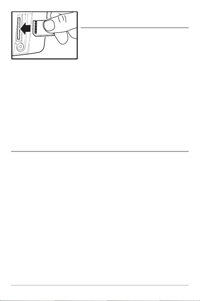
Multi-Media Card
(MMC)/SD Slot
Your 700 Series™ Chartplotter also has a multimedia card (MMC)/SD slot that is used to insert
optional-purchase cards containing additional
detailed maps. If you insert an MMC/SD that
contains a more detailed chart for a particular
location, your 700 Series™ Chartplotter will
retrieve that chart and display it automatically.
Use the illustration to locate the position of the MMC/SD slot cover, remove the
MMC/SD slot cover, then insert the MMC/SD into the slot. The label on the
MMC/SD should face toward the right side of the unit. Press down on the card
until it clicks into place, then replace the slot cover, making certain that the
gasket is present and positioned correctly before re-installing the cover, then
replace and tighten snugly - do NOT overtighten, as this will not improve water
resistance, and may damage the cover.
Software Updates
Use the MMC/SD slot to update the software version of your control head. To
update the software in your control head, plug in the appropriate MMC/SD card
that contains a software update file; the unit will recognize it, will tell you what
software version your control head is currently running, and will ask you if you
want to update the software in the unit to match that on the MMC/SD card.
You can obtain software updates from the www.humminbird.com website.
Inserting an MMC/SD
into the Card Slot
Page 12
4
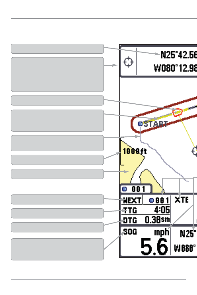
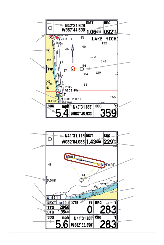
What’s On the Display
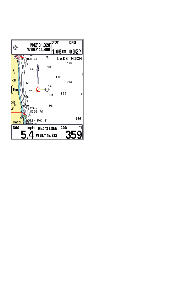
The 700 Series™ Chartplotter can display a variety of useful information.
Cursor Info Box: indicates the Latitude and Longitude of
the cursor position, the distance to travel to the cursor
position and the bearing to the cursor position is shown with
a GPS receiver. A waypoint can be marked at the cursor
position for later retrieval and use with a GPS receiver.
Boat Icon
Latitude and Longitude Position of Cursor
Map Scale
Route: Two or more linked waypoints that show
intended navigation and the shortest path from one
waypoint to the next.
Track: Detailed position history, displayed as a
breadcrumb trail of trackpoints.
Speed Over Ground: the measurement of the boat’s
progress across a given distance, and is the speed
measurement provided by GPS.
DTG: Distance to Go to Waypoint
Cartography
NEXT: Next Waypoint in the Route
TTG: Time to Go to Waypoint
Page 13
5
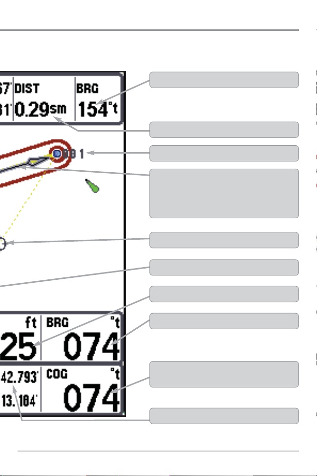
Active Cursor Icon
Course Over Ground: the current direction the boat is
traveling measured in degrees from North.
Waypoint
Selectable Readout Boxes
XTE: Cross Track Error: Distance of Boat from Route
Bearing to Waypoint
Bearing to Cursor
Latitude and Longitude Position of Boat
Distance to Cursor
Course Projection Line: Arrow extending from the
bow of the boat that projects your current course, and
shows where the boat will go if you continue on your
present course.
Page 14

6
Views
The views available on your
Chartplotter are:
• Bird's Eye No Readouts View
• Bird's Eye View
• Bird's Eye Big Digits View
• Chart No Readouts View
• Chart View
• Chart Big Digits View
• Instrument View
• Screen Snapshot View
• GPS Diagnostic View.
NOTE: When you change any menu settings that affect the display, the view will update
immediately (i.e. you don’t have to exit the menu to apply the change to the screen).
GPS Diagnostic View is the default view until GPS communications are
established. At that point, all the other views become available. When the
VIEW key is pressed, the display cycles through the available views. When the
EXIT key is pressed, the display cycles through the available views in reverse
order. Any view can be hidden or displayed as part of the view rotation using
the Views Menu tab. See Start-Up Options Menu for information about the
Self Test, Accessory Test, and GPS Diagnostic Views.
Bird’s Eye Bird’s Eye
No Readouts No Readouts
ViewView
Bird’s Eye
No Readouts
View
Bird’s Eye ViewBird’s Eye ViewBird’s Eye View
Bird’s Eye
Bird’s Eye
Big Digits ViewBig Digits View
Bird’s Eye
Big Digits View
ChartChart
No ReadoutsNo Readouts
ViewView
Chart
No Readouts
View
Chart
Chart
Big DigitsBig Digits
ViewView
Chart
Big Digits
View
Instrument
Instrument
ViewView
Instrument
View
Screen
Screen
SnapshotSnapshot
ViewView
Screen
Snapshot
View
Self Test
Self TestSelf Test
Accessory Test
Accessory TestAccessory Test
Chart
Chart
ViewView
Chart
View
GPS
GPS
Diagnostic Diagnostic
ViewView
GPS
Diagnostic
View
Page 15
7
Bird’s Eye Views
Bird's Eye Views - The Standard Bird's Eye, Bird's Eye Big Digits, and Bird's Eye No
Readouts Views show a 3-D, perspective view of the track and the chart’s land
contour from a point above and behind the boat (the eye point). As the boat turns,
the eye point moves to follow the boat.
When you press the 4-WAY Cursor key in the Bird’s Eye View, the position of the
eye point will shift. This allows you to move and turn the eye point so that you can
look off to the sides, or even behind the boat. Pressing the RIGHT or LEFT arrow
keys on the 4-WAY Cursor key turns the eye point right or left, while pressing
the UP arrow key moves the eye point forward, and pressing the DOWN arrow
key moves the eye point backward.
Pressing the EXIT key moves the eye point back to its original position behind
and above the boat.
NOTE: Standard Bird's Eye View and Chart View share the same set of 9 readouts, 7 of which
are adjustable. When you change the readouts display on the Bird's Eye View, you also are
changing them on the Chart View.
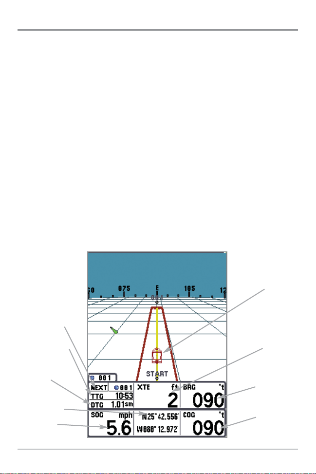
Bird’s Eye View
Next Waypoint
TTG: Time To Go
to Next Waypoint
DTG: Distance
To Go to Next
Waypoint
Latitude and
Longitude
Position of Boat
SOG: Speed
Over Ground
Boat Icon
XTE: Cross
Track Error
BRG: Bearing
COG: Course
Over Ground
Page 16
8
You may also choose Bird's Eye Big Digits View or Bird's Eye No Readouts
View if you prefer.
NOTE: Bird's Eye Big Digits View, Chart Big Digits View, and Instrument View all share the
same set of 8 readouts. When you change the readouts display on one of these three views,
you are also changing them on the other two views. See Navigation X-Press™ menu: Select
Readouts for more information.
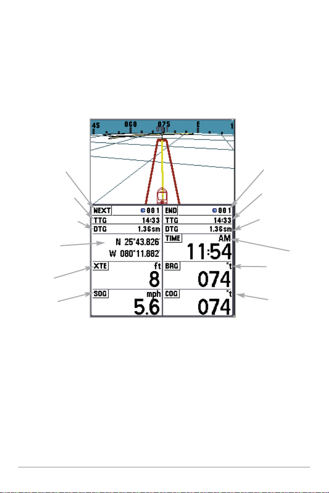
Bird's Eye Big Digits View
Next Waypoint
in the Route
TTG: Time to Go to
Next Waypoint
DTG: Distance to Go
to Next Waypoint
Latitude and
Longitude Position
of Boat
XTE: Cross
Track Error
SOG: Speed
Over Ground
Last Waypoint
in the Route
TTG: Time to Go
to Last Waypoint
DTG: Distance to
Go to Last
Waypoint
Time
BRG: Bearing
COG: Course
Over Ground
Page 17
9
Bird's Eye No Readouts View
Page 18
10
Chart Views
Chart Views - The standard Chart, Chart Big Digits, and Chart No Readouts Views
show cartography from the built-in UniMap™ or an optional MMC/SD map for
the area surrounding your current position. The current track (also known as the
position history or breadcrumb trail) showing where the boat has been, along
with saved tracks, waypoints, and the current route (when navigating), are
overlaid on the chart. You can use the 4-WAY Cursor Control key to shift/pan the
chart to another area. You can use the ZOOM (+/-) keys to zoom in and out. You
can use the INFO key to get information on the chart objects near the cursor.
NOTE: Standard Bird's Eye View and Chart View share the same set of 9 readouts, 7 of which
are adjustable. When you change the readouts display on the Bird's Eye View, you also are
changing them on the Chart View.
NOTE: Bird's Eye Big Digits View, Chart Big Digits View, and Instrument View all share the
same set of 8 readouts. When you change the readouts display on one of these three views,
you are also changing them on the other two views. See Navigation X-Press™ menu: Select
Readouts for more information.
Chart View without Active Cursor, shown with
Optional-Purchase Navionics® Cartography
Cartography
Map Scale
SOG: Speed
Over Ground
Latitude and
Longitude
Position of
Boat
COG: Course
Over Ground
Page 19
11
Chart View with Active Cursor, with Optional-Purchase Navionics® Cartography, Showing Navigation
COG: Course
Over Ground
Latitude and
Longitude
Position of Cursor
Cursor Info Box
Map Scale
Next Waypoint in
Route
TTG: Time To Go
to Next Waypoint
DTG: Distance To Go
to Next Waypoint
SOG: Speed Over
Ground
DIST: Distance to
Cursor
BRG: Bearing
to Cursor
Active Cursor
XTE: Cross Track Error
Cartography
BRG: Bearing
Latitude and Longitude
Position of Boat
Chart View with Active Cursor, shown
with Optional-Purchase Navionics® Cartography
Latitude and
Longitude
Position of
Cursor
Cursor Info Box
Cartography
Map Scale
Latitude and
Longitude
Position of Boat
SOG: Speed
Over Ground
COG: Course
Over Ground
DIST: Distance
to Cursor
BRG: Bearing
to Cursor
Active Cursor
Page 20
12
You may also choose Chart Big Digits View or Chart No Readouts View if you prefer.
Chart No Readouts View
Chart Big Digits View
Next Waypoint
in Route
TTG: Time to Go
to Next Waypoint
DTG: Distance
to Go to Next
Waypoint
Latitude and
Longitude of
the Boat
XTE: Cross
Track Error
SOG: Speed
Over Ground
Last Waypoint
in Route
TTG: Time to Go
to Last Waypoint
DTG: Distance to
Go to Last
Waypoint
Time
BRG: Bearing
COG: Course
Over Ground
Page 21
13
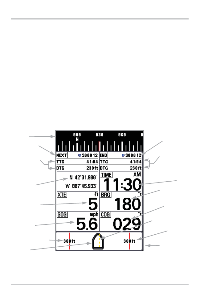
Instrument View
Instrument View allows you to display a digital instrument panel with 8
selectable readouts. This view provides a digital compass at the top of the view,
as well as 8 selectable readouts, and a Cross Track Error (XTE) graphic at the
bottom of the view. The XTE graphic shows the boat's position in relation to the
Off Course Alarm limits, as well as the optimal route (shown as the dotted line
in the middle). You should try to keep the boat as close to the dotted line as
possible for best results. If your course exceeds the Off Course Alarm limits, an
alarm will sound, and the boat icon will change position and will turn from
black to red to indicate the alarm state.
NOTE: Bird's Eye Big Digits View, Chart Big Digits View, and Instrument View all share the
same set of 8 readouts. When you change the readouts display on one of these three views,
you are also changing them on the other two views. See Navigation X-Press™ menu: Select
Readouts for more information.
NOTE: If there is only one waypoint in a route, the Next Waypoint and the End Waypoint info
boxes will display the same information, both for that next waypoint.
Instrument View
Compass
Next Waypoint
in Route
TTG: Time To Go
DTG: Distance To
Go to Next Waypoint
in Route
Latitude and
Longitude Position
of Boat
XTE: Cross Track
Error. Distance of
Boat from Route
SOG: Speed
Over Ground
Off Course Alarm Limit
Boat Icon
Last Waypoint
in Route
TTG: Time to Go,
DTG: Distance to
Go to Last
Waypoint in Route
Time
BRG: Bearing to
Next Waypoint
COG: Course
Over Ground
Recommended Route
Off Course
Alarm Limit
XTE: Cross Track
Error Graphic
Page 22
14
Screen Snapshot View
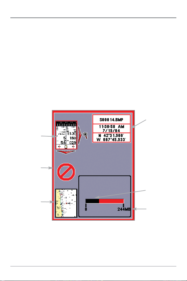
Screen Snapshot View displays and allows you to view screen snapshot
thumbnails captured to an optional-purchase MMC/SD card installed in your
unit. In addition, when you are in the Screen Snapshot View, Delete Image and
Delete All Images are added to the X-Press™ menu.
The Screen Snapshot View displays up to three screen snapshot thumbnails on
the screen at a time; you may have to scroll using the 4-WAY Cursor keys to see
the whole list of thumbnails in this view. The selected thumbnail will be
highlighted with arrows.
NOTE: The speed of the screen capture depends on the type of card you use; in general, SD
cards capture the screen faster than MMC cards do.
Screen Snapshot View
Total amount of
space on card
Information Box
Amount of space
left on the card
Unavailable icon
Highlighted
Screen Snapshot
Thumbnail
Screen Snapshot
Thumbnail
Page 23

15
Screen Snapshot: When Screen Snapshot is enabled (from the Accessories
menu tab), pressing the MARK key creates a saved screen capture (when you
have an optional-purchase MMC/SD card installed). Once you have created a
screen capture, a screen capture thumbnail is added to the Screen Snapshot
View, and is available to view at a later date. See the full-sized image by
highlighting a thumbnail (using the Up or Down 4-Way Cursor keys), then using
the Right 4-Way Cursor key to view the full image. A border around the full-size
screen snapshot indicates that it is just a screen snapshot, not a “live” view.
You can delete the selected image, or all images, by selecting a thumbnail and
using Delete Image, or using Delete All Images from the Screen Snapshot
X-Press™ menu.
W
orking with screen snapshots is a f
our-step process:
1. Enabling Screen Snapshot from the Accessories Menu.
2. Making a Screen Snapshot using the MARK key.
3. Viewing a Screen Snapshot using the Screen Snapshot View.
4. Deleting a Screen Snapshot using the Screen Snapshot X-Press™
menu.
For more information, see Accessories Menu Tab: Using Screen Snapshot and
Screen Snapshot X-Press™ Menu.
When you start a screen snapshot, you will see a message that a waypoint has
been created at the point where your cursor is on the screen, and the screen
will freeze while the snapshot is being saved to the MMC/SD card. A status
dialog box will appear that shows the progress of the save as a percentage, and
that displays the numbered file name assigned to the .BMP file that is being
created. Snapshot filenames begin with the letter "S". For more information,
see the Accessories Menu Tab: Using Screen Snapshot procedure and Screen
Snapshot X-Press™ Menu.
Page 24

16
View Orientation
All the Chart views allow you to choose the orientation of the view. When
North-Up orientation is selected, True North is shown at the top of the display.
In other words, objects located to the north of the boat are drawn above the
boat. When Course-Up orientation is selected, the direction of motion of the
boat is shown at the top of the display. In other words, objects ahead of the boat
are drawn above the boat. In both orientations, the view pans automatically, so
that the boat is always centered on the display. When the boat is stationary, it
is drawn as a circle. When the boat is in motion, it takes on a boat shape,
pointed in the direction of motion (always Up in the Course-Up orientation).
Page 25
17
Viewing Cartography
In the Chart Views, there are several cartography-related functions that you can
access using various keys.
Panning: Use the 4-WAY Cursor keys to
move the chart around on the display in
the direction of the key being pressed.
When you do this, a bull's eye cursor is
drawn at the center of the screen and is
linked to the boat by a gray line, even if
the boat is off the screen. At the same
time, the distance and bearing from the
boat to the cursor position and the
latitude/longitude coordinates of the
cursor are displayed in the upper info
boxes.
Zooming: Use the Plus (+) key to Zoom In
and the Minus (-) key to Zoom Out showing
the cartography at different scales. The
scale is indicated on the left side of the
display. If you zoom in beyond the available chart data, the display will go into
Overzoom mode whereby the last available chart data is amplified to reflect the
scale selected. If you zoom in so far that no cartography is available, a lat/lon
grid will be drawn instead.
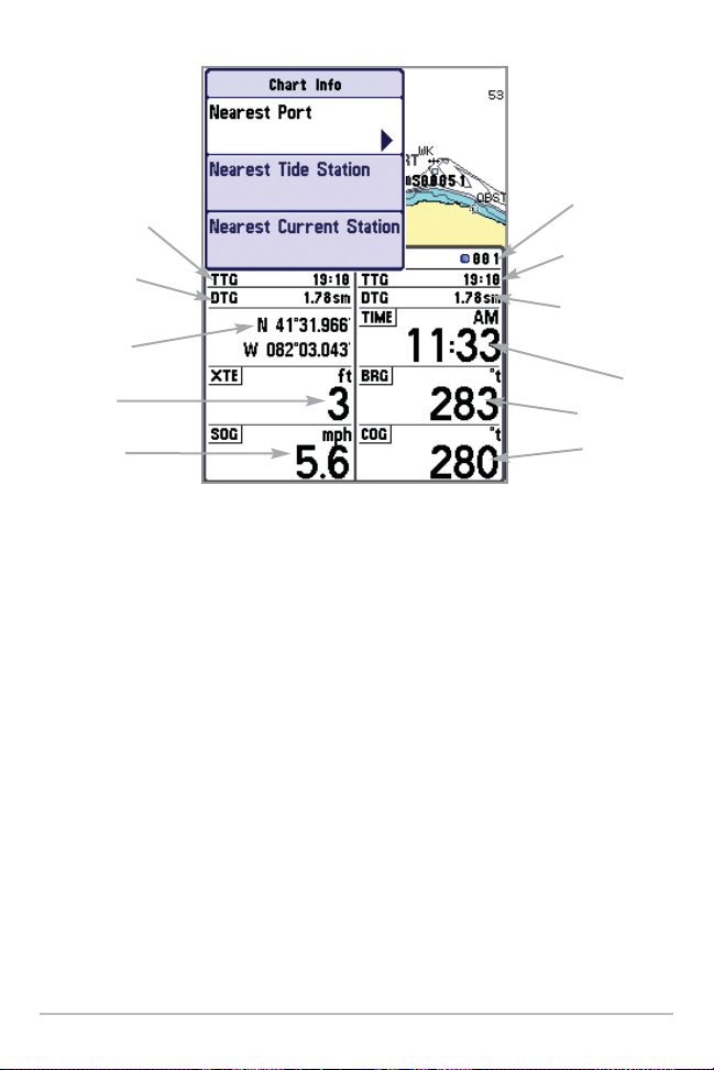
Chart Info: Use the INFO key to get detailed information about the chart
through the Chart Info submenu. If the cursor is active, you will see information
about the chart objects located near the cursor. If the cursor is not active, the
Chart Info menu will appear. You can select the nearest port, the nearest tide
station, or the nearest current station to see information about any of these
objects using the 4-WAY Cursor Control key.
NOTE: The built-in UniMap™ does not contain any Port, Tide or Current information. This
information is only available from optional-purchase MMC/SD cards.
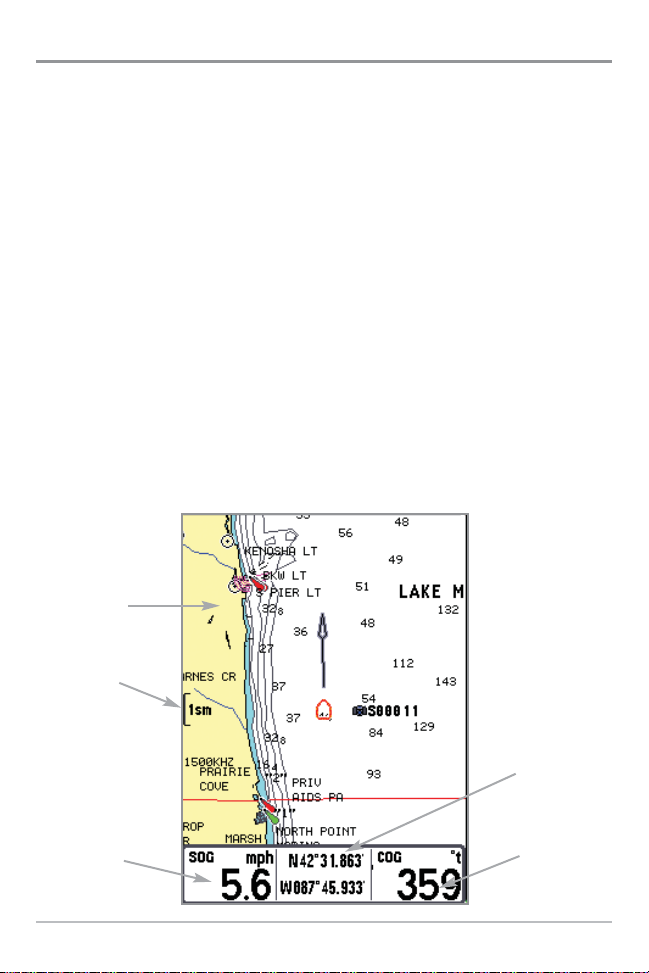
Chart View with Cursor Present,
shown with Optional-Purchase
Navionics® Cartography
Page 26
18
Nearest Port: The position and services information for the nearest port to your
present position will be displayed in an information box. Press the EXIT key to
remove the information box and the cursor bull’s eye will be centered over the
port position. The cursor information boxes at the bottom of the display will
indicate the distance and bearing to the port from your present position. Press
the EXIT key again to return to the Chart View.
Nearest Tide Station: Tide information for the nearest tide station to your
present position will be displayed in an information box. This includes the
position of the station and the times of the high and low tides for today’s date.
A tide graph is also displayed showing the rise and fall of the tides for the 24
hour time period encompassing the date. You can change the date to look at
tide information before or after the date displayed by pressing the LEFT or
RIGHT cursor key respectively. Press the EXIT key to remove the information box
and the cursor bull’s eye will be centered over the tide station position. The
cursor information boxes at the bottom of the display will indicate the distance
and bearing to the tide station from your present position. Press the EXIT key
again to return to the Chart View.
Chart Info Submenu
TTG: Time to Go
to Next Waypoint
DTG: Distance
to Go to Next
Waypoint
Latitude and
Longitude of Boat
XTE: Cross
Track Error
SOG: Speed
Over Ground
Last Waypoint
in Route
TTG: Time to Go
to Last Waypoint
DTG: Distance to
Go to Last
Waypoint
Time
BRG: Bearing
COG: Course
Over Ground
Page 27

19
Nearest Current Station: Current information for the nearest current station to
your present position will be displayed in an information box. This includes the
position of the station and the current changes for today. Two graphs are also
presented that show the time, direction and flow speed of the current changes
for the 24 hour time period of today’s date. You can change the date to look at
current information before or after the date displayed by pressing the LEFT or
RIGHT cursor key respectively. Press the EXIT key to remove the information box
and the cursor bull’s eye will be centered over the current station position. The
cursor information boxes at the bottom of the display will indicate the distance
and bearing to the current station from your present position. Press the EXIT
key again to return to the Chart View.
Introduction to Navigation
Use your Chartplotter to establish waypoints at areas of interest and to
navigate to those waypoints via a savable route (representing the shortest
intended distance between waypoints). You can also view and save tracks,
which represent the actual path of the boat.
Page 28
20
Waypoints, Routes and Tracks
Waypoints are stored positions that allow you to mark areas of interest or
navigation points. Your Chartplotter can store up to 3000 waypoints.
Routes link two or more waypoints together to create a path for navigation, and
are used in trip planning. You can link individual waypoints together by using the
GOTO key. A route represents your intended navigation and shows the shortest
path from each waypoint to the next. As you travel a route, staying on the route
line is the most efficient way to get to your destination, although you should
always look out for obstacles not shown on the chart. Your 700 Series™
Chartplotter can store up to 50 routes that can each contain up to 50 waypoints.
Tracks consist of detailed position history, and are displayed as a breadcrumb
trail of trackpoints. The Current Track shows the position history since the unit
was powered up (maximum of 20,000 trackpoints displayed). You can clear the
Current Track or save it at any time. Your 700 Series™ Chartplotter can store up
to 50 saved tracks, each containing 20,000 trackpoints. The current track
represents your actual path so far.
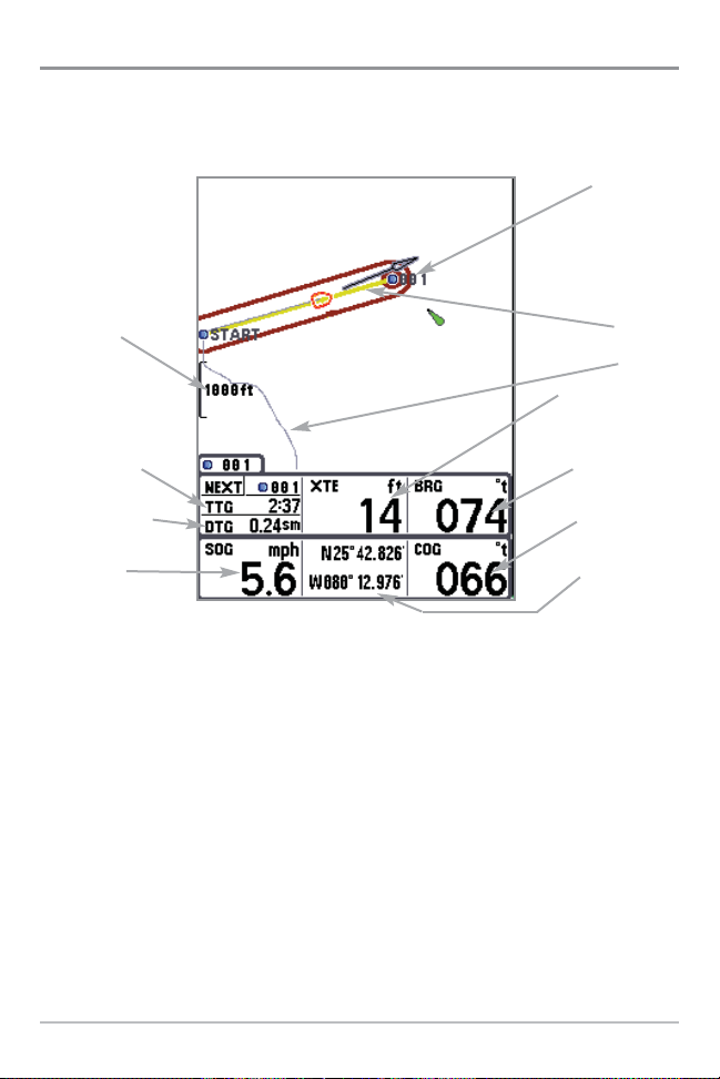
Waypoints, Routes and Tracks
Map Scale
TTG: Time to Go
to Waypoint
DTG: Distance to
Go to Waypoint
SOG: Speed
Over Ground
Waypoint
Route
Track
XTE: Cross Track
Error. Distance of
Boat from Route
BRG: Bearing
to Waypoint
COG: Course
Over Ground
Latitude and
Longitude
Position of Boat
Page 29

21
Save, Edit, or Delete a Waypoint
Save your current position as a waypoint: On any view, press the MARK key
to save the current position of the boat as a waypoint.
Save the cursor position as a waypoint: On the Chart views, use the Cursor
key to designate the position you want to save as a waypoint. Then press the
MARK key to save the marked position as a waypoint.
NOTE: When you save a waypoint by any of these methods, a numerical waypoint name
is automatically assigned. You can edit the waypoint information later to give it a different
name and select an icon to represent it (see Waypoint submenu on the Navigation Main
Menu Tab).
Display the Waypoints Submenu: From any view, press the MENU key twice
to display the Main Menu System, then use the RIGHT Cursor key to select the
Navigation tab. Select Waypoints and press the RIGHT Cursor key to display the
Waypoints submenu.
Program a specific position as a waypoint: To create a waypoint that is NOT
your current position, from the Waypoints submenu, select the Create option
and press the RIGHT Cursor key. Use the Cursor keys to program a waypoint
name, latitude, longitude, and icon before selecting Save.
Edit a waypoint: From the Waypoints submenu, select Edit and press the RIGHT
Cursor key to display a list of saved waypoints. Select the waypoint you want to
edit and press the RIGHT Cursor key. Use the 4-WAY Cursor Control key to move
from field to field, and the UP and DOWN Cursor keys to changes values once
you are in a field. In the Waypoint Name, Latitude and Longitude fields, use the
UP and DOWN Cursor keys to change the letter or number. All upper and lower
case letters are available, as well as digits 0-9 and some punctuation characters.
In the Waypoint Icon field, use the UP and DOWN Cursor keys to change the
icon used to represent the waypoint on the Chart views. You can exit these fields
with the LEFT and RIGHT Cursor keys or by pressing the EXIT key. Select Save
and press the RIGHT Cursor key to save your changes.
Page 30

22
To make it easier to select a waypoint, select Sort By and press the RIGHT or
LEFT Cursor keys to select a sort order:
• Name shows the waypoints alphabetically
• Time shows the most recently-created waypoint first
• Distance shows the closest waypoint first.
Delete a waypoint: From the Waypoints submenu, select Delete and press the
RIGHT Cursor key to display a list of waypoints. Select the waypoint you want
to delete, then press the RIGHT Cursor key. You will be asked to confirm
deletion before the waypoint is actually deleted.
Navigate to a Waypoint or Position
Navigate to the cursor position: From the Chart views, use the Cursor key to
select a position or waypoint to which you want to navigate. Press the GOTO
key. Navigation will begin immediately.
Navigate to a specified waypoint: Press the GOTO key, then choose the
waypoint to which you would like to navigate from the waypoint list and press
the RIGHT Cursor key to select it.
NOTE: By repeating the previous instructions, you can add more waypoints to create a longer
multi-segment route.
Skipping a waypoint: From the Navigation X-Press™ menu, select Skip Next
Waypoint and press the RIGHT Cursor key. If there is not another waypoint to
skip to, navigation will be cancelled.
Cancel navigation: From the Navigation X-Press™ menu, select Cancel
Navigation and press the RIGHT Cursor key. Canceling navigation removes the
route and any waypoints created using the GOTO key, but does not remove any
saved routes from memory. You will be prompted to save the current route
when you cancel navigation.
Page 31

23
Add a Waypoint Target or Trolling Grid
Add or Remove a Waypoint Target: From the Waypoints submenu, select
Target and press the RIGHT Cursor key to display a list of waypoints. Select the
waypoint you want to target. A target consisting of concentric circles centered
on the selected waypoint will appear on all of the navigation views; the target
shows various distance ranges from the targeted waypoint. To remove the
target, choose Remove Target from the Navigation X-Press™ menu.
Chart View with Target
Waypoint
Target
Page 32

24
Add or Remove a Trolling Grid: From the Waypoints submenu, select Grid and
press the RIGHT Cursor key to display a list of waypoints. Select the waypoint
to which you want to add the grid. The trolling grid will appear on all of the
navigation views, and can be used as a guide when trolling around a waypoint.
The grid can be rotated to any desired heading using Grid Rotation from the
Navigation Main menu. To remove the trolling grid, choose Remove Grid from
the Navigation X-Press™ menu.
Chart View with Grid
Waypoint
Trolling
Grid
Waypoint
Page 33

25
Save, Edit or Delete a Route
Save the current route: While you are navigating, the current route can be
saved. From the Navigation X-Press
™
menu, select Save Current Route and
press the RIGHT Cursor key. Navigation will continue.
Display the Routes submenu: From any view, press the MENU key twice to
display the Main Menu System, then use the RIGHT Cursor key to select the
Navigation tab. Select Routes and press the RIGHT Cursor key to display the
Routes submenu.
Create a route: From the Routes submenu, select Create and press the RIGHT
Cursor key. A Route Edit screen will be displayed with an empty route. You can
name the route, add waypoints to the route from the list of all waypoints, and
order the waypoints in the route using the Cursor keys.
Edit a saved route: From the Routes submenu, select Edit and press the RIGHT
Cursor key. A Route Edit screen will be displayed. Select the route you wish to
edit and press the RIGHT Cursor key. Re-name the route or change, delete or
re-order the waypoints used in the route.
Delete a saved route: From the Routes submenu, select Delete and press the
RIGHT Cursor key. Select the route you wish to delete and press the RIGHT
Cursor key. You will be asked to confirm your choice by pressing the RIGHT
Cursor key again before the route is deleted.
Travel a saved route: From the Routes submenu, select Travel and press the RIGHT
Cursor key. A list of saved routes will appear. Select the route you wish to travel
and press the RIGHT Cursor key to make this route the current route and begin
navigation. You may also travel the route in either forward or reverse order.
Route Info: From the Routes submenu, select Info and press the RIGHT Cursor
key. A list of saved routes will appear. Select the route for which you want
information, and press the RIGHT Cursor key. The list of waypoints in the route
will be shown, with the distance and bearing from each waypoint to the next,
as well as the distance and bearing from the current position to the first
waypoint in the route.
Page 34

26
Save or Clear a Current Track
Save the current track: From the Navigation X-Press™ menu, select Save
Current Track and press the RIGHT Cursor key. The track will remain on the
display, but will change from black to gray. To remove the track completely from
the display, see Edit, Delete or Hide Saved Tracks.
NOTE: When you save a track, a name is automatically assigned. The track name consists of
a date/time stamp, but can be re-named later (see Edit a Saved Track).
Clear the current track: From the Navigation X-Press™ menu, select Clear
Current Track and press the RIGHT Cursor key. The track will be removed from
the display and discarded.
Edit, Delete or Hide Saved Tracks
Display the Tracks Submenu: From any view, press the MENU key twice to
display the Main Menu System, then use the RIGHT Cursor key to select the
Navigation tab. Select Tracks and press the RIGHT Cursor key to display the
Tracks submenu.
Edit a saved track: From the Tracks submenu, select Edit and press the RIGHT
Cursor key to display the list of saved tracks. Select the track you want to edit and
press the RIGHT Cursor key. When the Edit Track dialog box appears, use the
Cursor keys to move between fields. In the Track Name field, the UP and DOWN
Cursor keys change the letter or number. All upper and lower case letters are
available, as well as digits 0-9 and some punctuation characters. You can exit the
Track Name field with the LEFT and RIGHT Cursor keys or by pressing the EXIT key.
Select Save and press the RIGHT Cursor key to save your changes.
Delete a saved track: From the Tracks submenu, select Delete and press the
RIGHT Cursor key to display the list of saved tracks. Select the track you want
to delete and press the RIGHT Cursor key. You will be asked to confirm deletion
before the track is actually deleted.
Hide or display a saved track: From the Tracks submenu, select Visibility and
press the RIGHT Cursor key to display the list of saved tracks. Select the track
you want to hide or display and use the Cursor keys to select Hidden or Visible.
Press the EXIT key to return to the Tracks submenu.
Page 35

27
Man Overboard (MOB) Navigation
As soon as you know that you have a man overboard, you should activate MOB
navigation to maximize chances for a successful rescue. MOB navigation
allows you create an MOB waypoint to locate the point at which your man went
overboard, and the relation of the boat to that point. When MOB is activated,
an MOB waypoint, which is a permanent, sharable waypoint with a large,
distinctive icon, is created at the boat's current position (regardless of whether
the chart cursor is active or not). Any current navigation will be cancelled and
the current route discarded without user notification, and MOB navigation will
begin immediately. A line will be drawn from the boat's current position to the
MOB waypoint, and the MOB waypoint will be targeted. The view is switched
to the Chart View automatically when MOB is activated, and an additional info
box that shows the lat/lon position of the MOB waypoint and the elapsed time
since MOB was activated is added to the Chart View. This information will
automatically be added to the Bird's Eye and Instrument Views as well.
It is not possible to re-activate MOB or modify the current route without first
canceling MOB navigation. The Off Course trigger is also disabled and the Off
Course Alarm circle is not drawn. Any press of the GOTO key, or selection of a
GOTO menu item, will cause an error beep and a short message will be
displayed to the user that will disappear after 2 seconds.
Activate MOB navigation: Press and hold the GOTO key for more than 1.5
seconds to activate the Man Overboard (MOB) function.
Cancel MOB navigation: From the Navigation X-Press™ menu, select Cancel
MOB and press the RIGHT Cursor key. Canceling MOB navigation removes the
route and any waypoints created using the GOTO key, but does not remove any
saved routes from memory, nor does it remove the MOB waypoint. To delete the
MOB waypoint after you have cancelled MOB navigation, use the Navigation
X-Press™ menu to select the MOB Waypoint, then press the RIGHT Cursor key
to view the MOB Waypoint submenu, then use the 4-WAY Cursor Control keys
to delete the MOB Waypoint.
NOTE: The actual MOB waypoint will remain in the Navigation X-Press™ menu until you
delete it manually. To delete the MOB waypoint after you have cancelled MOB navigation,
select it from the Navigation X-Press™ menu using the RIGHT 4-WAY Cursor Control key, then
select Delete from the MOB Waypoint submenu. A confirmation dialog box will appear,
allowing you to confirm the deletion or to cancel it.
Page 36

28
Man Overboard (MOB) Navigation
Target surrounding
MOB waypoint
MOB waypoint
Line Drawn to
MOB Waypoint
from Boat's
Current Position
Boat's current
position
Bearing to
MOB Waypoint
Latitude and
Longitude of
Boat's Position
COG: Course
Over Ground
Name of MOB
Waypoint
Elapsed time
since MOB was
activated
Position where
man fell overboard
SOG: Speed
Over Ground
Page 37

29
Key Functions
Your Chartplotter user interface consists of a set of easy-to-use keys that work
with various on-screen views and menus to give you flexibility and control over
your fishing experience.
POWER/LIGHT Key
The POWER/LIGHT key is used to turn the Chartplotter on and off,
and also to adjust the backlight and background color of the
display. Press the POWER/LIGHT key to turn the unit on. The Title
screen is then displayed until the Chartplotter begins operation.
See Powering Up the Unit for a more detailed explanation of the
different modes you can select on power up.
To adjust the backlight, or to adjust the display
background color, press the POWER/LIGHT key
to access the Light and Background menu. Use
the 4-WAY Cursor key to select Light or
Background and then use the LEFT or RIGHT
Cursor key to change the settings. Press EXIT to
exit the Light and Background menu.
Press and hold the POWER/LIGHT key for 3 seconds to turn the unit off. A
message will appear telling you how many seconds there are until shutdown
occurs. Your Chartplotter should always be turned off using the POWER/LIGHT
key. This will ensure that shutdown occurs properly and any menu settings will
be saved.
VIEW Key
The VIEW key is used to cycle through all available views. Press
the VIEW key to advance to the next view. Repeatedly pressing
VIEW cycles through all views available. Views can be hidden
to optimize the system to your fishing requirements (see
Views Menu Tab).
Page 38

30
INFO Key
Info - Press the INFO key while in the Bird's Eye or Chart views
to display information about objects that are nearest to an active
cursor.
If the cursor is not active, the following menu
will be displayed. Use the 4-WAY Cursor key to
select Nearest Port, Nearest Tide Station or
Nearest Current Station, then use the RIGHT
Cursor key to display the requested information.
NOTE: The built-in UniMap™ does not contain Port, Tide
or Current information. This information is only available
from optional purchase MMC/SD cards.
MENU Key
The MENU key is used to access the menu system.
Start-Up Options Menu - Press the MENU key during the power up sequence
to view the Start-Up Options menu.
X-Press™ Menu - Press the MENU key once for the X-Press™ Menu. The
X-Press™ menu allows you to access frequently-used settings without having
to navigate through the whole menu system. When the X-Press™ menu is
displayed, you can use the UP or DOWN Cursor keys to move to a particular
menu choice. As soon as you alter a parameter (using the RIGHT or LEFT Cursor
keys) the X-Press™ menu will collapse temporarily, and the screen will update
if it is affected by your menu setting change, allowing you to see the effects of
your action immediately. Reactivate the X-Press™ Menu by using the UP or
DOWN Cursor keys.
Main Menu - Press the MENU key twice for the tabbed Main Menu System.
The Main Menu System is organized under tabbed headings to help you find a
specific menu item quickly: Alarms, Navigation, Chart, Setup, Views and
Accessories tabs are part of your tabbed Main Menu System. Use the LEFT or
RIGHT 4-WAY Cursor Control key to select a tab; then use the DOWN or UP key
to select the menu item, and the LEFT or RIGHT key to alter a menu setting.
Page 39

31
4-WAY Cursor Control Key
Use the DOWN or UP 4-Way Cursor Control keys to select a
menu choice from the menu list, then use the LEFT or RIGHT
arrow keys to change a menu setting.
NOTE: Menu choices are implemented and saved immediately - no further action is required.
MARK Key
Press the MARK key while in any view to mark the position of a
waypoint, either at the current boat location, or, if the Cursor is
active, at the current Cursor location.
The MARK key only functions if you have the GPS receiver connected, or if you
have enabled Screen Snapshot from the Accessories menu tab. If you have
enabled the Screen Snapshot feature, pressing the MARK key still creates a
waypoint, but it also captures the screen image to the optional-purchase
MMC/SD card.
NOTE: You must have an optional-purchase MMC/SD card installed for the screen snapshot
feature to work.
Navigation is not affected by the Screen Snapshot feature. Also, if Screen
Snapshot is enabled but there is no GPS receiver connected, pressing the
MARK key will capture the screen image and display an error saying that a GPS
position fix is required to create a waypoint.
GOTO Key
The GOTO Key has multiple functions, depending on the situation:
• If the Cursor is active, pressing the GOTO key while in any view creates
a waypoint and starts navigation towards that waypoint. If the Cursor is
not active, pressing the GOTO key displays the list of waypoints, so that
you can select the waypoint towards which you want to navigate.
• If the GOTO key is pressed and held for more than 1.5 seconds, the Man
Overboard (MOB) function is activated. When MOB is activated, an
MOB waypoint, which is a permanent, sharable waypoint with a large,
Page 40

32
distinctive icon, is created at the boat's current position (regardless of
whether the chart cursor is active or not). Any current navigation will be
cancelled and the current route discarded without user notification, and
MOB navigation begins immediately. The view is switched to the Chart
View automatically when MOB is activated, and it is not possible to
activate MOB or modify the current route without first canceling MOB
navigation. Any press of the GOTO key, or selection of a GOTO menu
item, will cause an error beep and a short message will be displayed to
the user that will disappear after 2 seconds.
ZOOM (+/-) Key
Press the - or + ZOOM keys while in any of the Chart or Bird's
Eye Views to change the scale of the view to appear closer
or farther away.
EXIT Key
The EXIT key has multiple functions, depending on the situation:
• If an alarm is sounding, pressing EXIT will cancel the alarm.
• If a menu tab is selected, pressing EXIT will exit the menu mode and
return to the view.
• If a menu is active, pressing EXIT will return to the previous level in the
menu system.
• Pressing EXIT will cycle through the available views in reverse order.
• If the Cursor is active, pressing EXIT will remove the cursor from the display.
Page 41

33
Accessory Bus
Use the Accessory Bus to expand the functionality of your Chartplotter.
Accessories plug directly into the Chartplotter, enabling Advanced features
such as WeatherSense® and the SmartCast® Wireless Sonar Link. Additional
tabs and menu choices will be added to the menu system automatically when
an accessory is plugged into the unit. In addition, multiple accessories can
be attached simultaneously. See Accessories Menu Tab and 700 Series™
Chartplotter Accessories in this manual, as well as your accessory's
Operations Manual for additional details.
NOTE: Accessories to enable WeatherSense® and the SmartCast® Wireless Sonar Link require
separate purchases. You can visit our website at www.humminbird.com or contact our
Customer Resource Center at 1-800-633-1468 for additional details.
Page 42

34
Powering Up the Unit
Turn on your Chartplotter by pressing the POWER/LIGHT key. The Title screen
is displayed until the Chartplotter begins operation. After the Title screen is
displayed, a 30 second Navigation Warning screen is shown. Press the MENU
key during the time that the Title screen is displayed to view the Start-Up Menu
in order to choose Simulator mode. Press the EXIT key during the Navigation
Warning to enter into Normal mode. If you don't press any key during the
Navigation Warning, and Demonstration is turned on, your Chartplotter
automatically goes into Demonstration Mode. You can turn off Demonstration
Mode if desired (see Setup Menu: Demonstration).
785c2Title Screen
Page 43

35
The Menu System
The menu system is divided into easy-to-use menu modules. The main
components of the menu system are:
Start-Up Options Menu - Press the MENU key during the power up sequence
to view the Start-Up Options menu.
X-Press™ Menu - The X-Press™ Menu allows
you to access the settings that are changed
frequently without having to navigate through the
whole menu system. Press the MENU key once to
display the X-Press™ Menu. When you select a
menu item from the X-Press™ Menu, the menu
will collapse, leaving only the menu choice on the
screen. Use the UP or DOWN Cursor keys to
reactivate the X-Press™ Menu.
NOTE: The X-Press™ Menu choices will vary
depending on which view is active when you press the
MENU key, as well as whether you are in Normal or
Advanced User Mode. Either the Navigation or Screen
Snapshot X-Press™ Menu will appear, depending on
the view you are in.
X-Press™ Menu
Page 44

36
Main Menu Tabs - Less frequently-adjusted
menus are grouped into the Main Menu
System. The Main Menu system is organized
under the following tab headings to help
you find a specific menu item quickly: Alarms,
Navigation, Chart, Setup, Views and
Accessories.
Press the MENU key twice for the Main Menu, then use the 4-WAY Cursor LEFT
or RIGHT key to select a tab, and use the DOWN or UP key to select a specific
menu item under that tab, then use the LEFT or RIGHT keys again to change a
menu setting. Press the EXIT key to move quickly to the top of the tab. A down
arrow at the bottom of a menu means that you can scroll to additional menu
choices using the DOWN Cursor key. A right or left arrow on a menu choice
means that you can use the RIGHT or LEFT Cursor keys to make changes or to
see more information.
NOTE: The Main Menu choices will vary depending on whether you are in Normal or
Advanced User Mode.
User Mode (Normal or Advanced) - An Advanced Mode is provided for users
who desire the highest level of control over the Chartplotter and Normal Mode
for users who desire greater simplicity and fewer menu choices. Additional
Advanced menu choices will be displayed throughout the menu system when
you navigate to specific menus while in Advanced Mode. Any changes made
while in Advanced Mode will remain in effect after you switch back to Normal
Mode. See Setup Menu Tab: User Mode for specific instructions on changing
to Advanced User Mode.
Main Menu System
Normal User Mode
Page 45

37
Total Screen Update - when you change any menu settings that affect the
display, the view will update immediately (i.e. you don’t have to exit the menu
to apply the change to the screen).
Setup Tab, Normal Mode
Setup Tab, Advanced Mode
Page 46

38
Start-Up Options Menu
Press the MENU key when the Title screen is displayed to access the Start-Up
Options menu.
Use the UP or DOWN 4-WAY Cursor keys to position the cursor, then the RIGHT
Cursor key to select one of the following choices. If you wait too long, the
system will default to whichever menu mode happens to be highlighted:
• Normal
• Simulator
• System Status
• PC Connect (use with PC Connect Cable).
See the following paragraphs for more information about each of these choices.
Normal Operation
Use Normal Operation for on the water operation. Turn on your Chartplotter by
pressing the POWER/LIGHT key. The Title screen is displayed until the
Chartplotter begins operation. After the Title screen is displayed, a 30 second
Navigation Warning screen is shown. Press the MENU key during the time that
the Title screen is displayed to view the Start-Up Menu in order to choose
Simulator mode. Press the EXIT key during the Navigation Warning to enter into
Normal mode.
Page 47

39
Simulator
Use the Simulator to learn how to use your Chartplotter before taking your boat
on the water. The Simulator is a very powerful tool that simulates on the water
operation, providing a randomly-updated display. We recommend going
through this manual while using the Simulator, since all of the menus function
and affect the display the way they actually do when in Normal operation.
NOTE: At startup, while still on the splash screen (while the name of your Humminbird(r)
model is still on the screen) you must press the MENU key and then select Simulator manually
to enter Simulator mode. Manually selecting Simulator from the Start-Up Options menu
allows you to pre-configure your Chartplotter for on the water operation. Any menu changes
you make will be saved for later use.
A message will appear on the display periodically to remind you that you are
using the Simulator.
Exit the Simulator by powering your Chartplotter off.
Simulator (shown with optional-purchase
Weathersense® attached)
Page 48

40
System Status
Use System Status to view system connections and to conduct a unit self-test.
The following screens are displayed in turn when you press the VIEW button
when using System Status:
• Self Test
• Accessory Test
• GPS Diagnostic View.
Exit System Status by powering your Chartplotter off.
Self Test
Self Test displays results from the internal diagnostic self test, including unit
serial number, Printed Circuit Board (PCB) serial number, software revision,
total hours of operation and the input voltage.
Self Test Screen
Page 49

41
Accessory Test
Accessory Test lists the accessories connected to the system.
NOTE: The speed accessory will be detected only if the paddlewheel has moved since your
Chartplotter was powered up.
System Status Accessory Test Screen
Page 50

42
GPS Diagnostic View
GPS Diagnostic View shows a sky chart and numerical data from the GPS
receiver. The sky chart shows the location of each visible GPS satellite with its
satellite number and a signal strength bar. A dark gray bar indicates that the
satellite is being used to determine your current position. A light orange bar
indicates that the satellite is being monitored, but is not yet being used.
This view also reports the current position, local time and date, and other
numeric information. The current GPS Fix Type is reported as No Fix, 2D Fix, 3D
Fix, or Enhanced. An Enhanced fix has been augmented using information from
WAAS, EGNOS, or MSAS. A 3D or Enhanced Fix is required for navigation.
HDOP (the Horizontal Dilution of Precision) is a GPS system parameter which
depends on the current satellite configuration. HDOP is used to calculate the
Estimated Position Error.
GPS Diagnostic View
Satellite Being
Monitored
Satellite
Being Used
Current Latitude
and Longitude
Sky Chart
Page 51

43
PC Connect (with PC Connect cable only)
Use PC Connect to update the software of the Chartplotter control head. This
feature requires the use of the PC Connect Cable. Complete instructions are
included with the PC Connect Cable accessory.
NOTE: The PC Connect Cable requires a separate purchase. For more information visit
our website at www.humminbird.com or contact our Customer Resource Center at
1-800-633-1468.
Exit PC Connect mode by powering the Chartplotter off.
Page 52

44
Navigation X-Press™ Menu
(Navigation views only)
The Navigation X-Press™ menu provides
access to the settings most frequently used.
Press the MENU key once while in any of the
Navigation views to access the Navigation
X-Press™ menu.
NOTE: Menu choices will vary depending on system
settings, such as whether you are currently navigating.
Navigation X-Press™ Menu
Page 53

45
Waypoint [Name]
(Only with an active cursor on a waypoint)
Waypoint [Name] allows you to view the Waypoints submenu for the waypoint
under your cursor.
T
o view the Waypoint [Name] Submenu:
1. Move the cursor onto an existing waypoint and press the MENU key
once, or use Cursor to Waypoint to select a waypoint from a list of
saved waypoints.
2. Highlight Waypoint [Name] on the Navigation
X-Press™ menu.
3. Use the RIGHT 4-Way Cursor Control key to view the Waypoints
submenu, which contains the following menu choices:
T
he Waypoint Submenu contains the following menu choices:
Edit allows you to edit the Name, Position (Latitude and Longitude) and select
the Icon that will be used to represent the waypoint in the Chart Views.
Delete allows you to delete a waypoint from the list of saved waypoints.
Target allows you to apply a target to a waypoint selected from the list of
waypoints.
Grid allows you to apply a trolling grid to a waypoint selected from the list of
waypoints.
Waypoint Submenu
Page 54

46
Cursor to Waypoint
(Chart views only)
Cursor to Waypoint allows you to quickly move the cursor to any saved
waypoint, so that you can locate it or edit it.
NOTE: This X-Press™menu item appears only if you have saved waypoints.
To move cursor to a saved waypoint:
1. Highlight Cursor to Waypoint on the Navigation X-Press™ menu.
2. Use the RIGHT 4-WAY Cursor Control key to initiate Cursor to
Waypoint.
3. Use the UP or DOWN 4-WAY Cursor Control key to highlight the
waypoint you wish to move the cursor to, then use the RIGHT 4-WAY
Cursor Control key to select the destination waypoint.
Save Current Track
Save Current Track allows you to save the current
track being displayed. After the current track is saved, a new current track is
started.
T
o Save Current Track:
1. Highlight Save Current Track on the Navigation X-Press™ menu.
2. Use the RIGHT 4-WAY Cursor Control key to initiate saving the current
track.
3. The Confirm dialog box will appear. To save the current track, press the
RIGHT Cursor key once more. To cancel saving the current track, press
the LEFT Cursor key.
Page 55

47
Clear Current Track
Clear Current Track allows you to clear the
current track being displayed and start a new track at the present position.
T
o Clear Current Track:
1. Highlight Clear Current Track on the Navigation X-Press™ menu.
2. Use the RIGHT 4-WAY Cursor Control key to initiate clearing the current
track.
3. The Confirm dialog box will appear. To clear the current track, press the
RIGHT Cursor key once more. To cancel clearing the current track, press
the LEFT Cursor key.
Save Current Route
(only when Navigating)
Save Current Route allows you to save the current route being displayed. This
menu choice will only appear when you are currently navigating a route.
T
o Save Current Route:
1. Highlight Save Current Route on the Navigation X-Press™ menu.
2. Use the RIGHT 4-WAY Cursor Control key to initiate saving the current
route.
3. The Confirm dialog box will appear. To save the current route, press the
RIGHT Cursor key once more. To cancel saving the current route, press
the LEFT Cursor key.
Page 56

48
Skip Next Waypoint
(only when Navigating)
Skip Next Waypoint removes the next waypoint from the current route. This
menu choice will only appear when you are currently navigating a route.
T
o Skip Next Waypoint:
1. Highlight Skip Next Waypoint on the Navigation X-Press™ menu.
2. Use the RIGHT 4-WAY Cursor Control key to initiate skipping the next
waypoint.
3. The Confirm dialog box will appear. To skip the next waypoint, press the
RIGHT Cursor key once more. To cancel skipping the next waypoint,
press the LEFT Cursor key.
Cancel Navigation
(only when Navigating)
Cancel Navigation discards the current route and exits Navigation Mode. This
menu choice will only appear when you are currently navigating a route. This
will not delete a previously-saved route.
T
o Cancel Navigation:
1. Highlight Cancel Navigation on the Navigation X-Press™ menu.
2. Use the RIGHT 4-WAY Cursor Control key to initiate canceling
navigation.
3. The Confirm dialog box will appear. To cancel navigation, press the
RIGHT Cursor key once more. To avoid canceling navigation, press the
LEFT Cursor key.
Page 57

49
Cancel MOB Navigation
(only when MOB Navigation is activated)
Cancel MOB Navigation exits Man Overboard mode. This menu choice will
only appear when you are currently navigating in Man Overboard mode.
T
o Cancel MOB Navigation:
1. Highlight Cancel MOB Navigation on the Navigation X-Press™ menu.
2. Use the RIGHT 4-WAY Cursor Control key to initiate canceling MOB
navigation.
3. The Confirm dialog box will appear. To cancel MOB navigation, press
the RIGHT Cursor key once more. To avoid canceling MOB navigation,
press the LEFT Cursor key.
NOTE: The actual MOB waypoint will remain in the Navigation X-Press™ menu until you
delete it manually. To delete the MOB waypoint after you have cancelled MOB navigation,
select it from the Navigation X-Press™ menu using the RIGHT 4-WAY Cursor Control key, then
select Delete from the MOB Waypoint submenu. A confirmation dialog box will appear,
allowing you to confirm the deletion or to cancel it.
Remove Target
(only if a Target is Active)
Remove Target removes the waypoint target from the display. This menu
choice will only appear when a target has already been applied to a waypoint.
NOTE: See Add a Waypoint Target or Trolling Grid for more information.
To Remove a Target:
1. Highlight Remove Target on the Navigation X-Press™ menu.
2. Use the RIGHT 4-WAY Cursor Control key to remove the target.
Page 58

50
Remove Grid
(only if a Grid is Active)
Remove Grid removes the waypoint grid from the display. This menu choice will
only appear when a grid has already been applied to a waypoint.
NOTE: See Add a Waypoint Target or Trolling Grid for more information.
To Remove a Grid:
1. Highlight Remove Grid on the Navigation X-Press™ menu.
2. Use the RIGHT 4-WAY Cursor Control key to remove the grid.
Waypoint [Name]
(Most recently-created waypoint)
Waypoint [Name] allows you to view the waypoints submenu for the most
recently created waypoint.
NOTE: You must have pressed the MARK key at least once since you last powered up the
Chartplotter for this menu choice to appear.
To vie
w the Waypoint [Name] Submenu:
1. Move the cursor to the desired position and press the MARK key once
to save a waypoint.
2. Highlight Waypoint[Name] on the Navigation X-Press™ menu.
3. Use the RIGHT 4-Way Cursor Control key to view the Waypoints
submenu.
Waypoint [Name] Submenu
Page 59

51
The Waypoint Submenu contains the following menu choices:
Edit allows you to edit the Name, Position (Latitude and Longitude) and select
the Icon that will be used to represent the waypoint in the Chart Views.
Delete allows you to delete a waypoint from the list of saved waypoints.
Go To allows you to select a waypoint and start navigation toward that
waypoint, or add that waypoint to the end of the current route.
Target allows you to apply a target to a waypoint selected from the list of
waypoints.
Grid allows you to apply a trolling grid to a waypoint selected from the list of
waypoints.
Page 60

52
Select Readouts
Select Readouts sets individual digital readouts on the Instrument View, all the
Chart Views, and the Bird's Eye Views. This feature allows you to select what data
will be displayed in each of a variable number of fixed-position data windows
arranged around the edges of the screen on various views, or whether a particular
window will be turned off, displaying nothing in that area. Data windows can
display readouts from supported accessories such as Temp/Speed.
NOTE: Standard Bird's Eye View and Chart View share the same set of 9 readouts, 7 of which
are adjustable. When you change the readouts display on the Bird's Eye View, you also are
changing them on the Chart View.
NOTE: Bird's Eye Big Digits View, Chart Big Digits View, and Instrument View all share the
same set of 8 readouts. When you change the readouts display on one of these three views,
you are also changing them on the other two views. See Bird's Eye View, Chart View, and
Instrument View for more information.
Select Readouts: 8 Data Windows
Used by Bird's Eye Big Digits,
Chart Big Digits,
and Instrument View
Select Readouts: 9 Data Windows,
7 Adjustable, Used by Standard
Bird's Eye and Chart View
Page 61

53
Each data window can either be empty or contain one of the following (varies
by position and by view):
COG
Off
Position
SOG
Time
Time + Date
Triplog
Voltage
Course Over Ground; Course Over Ground is the current
direction the boat is traveling measured in degrees from North
(i.e. 321°, where 000° is North, 090° East, 180° is South, 270°
is West). When the Course Over Ground is equal to Bearing, the
boat is said to be “On Course” and will arrive at the destination
in the most efficient manner. See the Glossary for more
information.
Suppresses the readout so that no data shows in that position.
Position is the current location (latitude, longitude) determined
by GPS.
Speed Over Ground; Speed Over Ground is the measurement of
the boat’s progress across a given distance, and is the speed
measurement provided by GPS; accurate destination times can
be derived from this measurement. See the Glossary for more
information.
The current time.
The current time and date.
Displays the triplog, which measures the elapsed time since last
reset, the distance traveled since last reset, and average speed
during timed interval.
Power supplied to the control head.
9 Data Windows, 7 Adjustable, Used by Standard Bird's Eye and Chart Views
Readouts 1, 2, 3, 6 and 7
Page 62

54
Bearing
CMG/SMG
Off
TRK/CMG
TTG
VMG
WPTend/ETA/DTG
Bearing is the direction to a destination waypoint measured
in degrees from North (i.e. 321°, where 000° is North, 090°
East, 180° is South, 270° is West).
Course Made Good/Speed Made Good.
Course Made Good is the angle between the starting point
on a route and the current position of the boat. The goal is
to have CMG and Track equal to the same number. See the
Course Made Good illustration. Speed Made Good is the
distance from the starting waypoint on the route divided by
the time elapsed since starting navigation on the route.
Suppresses the readout so that no data shows in that position.
Track/Course Made Good.
The Track is the desired line of travel between two
waypoints, and represents the most efficient path between
the two points because it is a straight line. The TRK is
measured in degrees. See above for an explanation of
Course Made Good.
Time To Go.
Time To Go is the estimated time required to reach the
destination waypoint. TTG is calculated using the SOG and DTG.
Velocity Made Good.
Velocity Made Good is the speed of travel relative to the next
waypoint on the route. The goal is for VMG to equal Speed.
Waypoint End/Estimated Time of Arrival/Distance to Go.
Waypoint End is the last waypoint on the route. Estimated
Time of Arrival is the estimated time of arrival to the last
waypoint on the route. Distance To Go is the distance
between the current position of the boat and the last
waypoint on the route.
9 Data Windows, 7 Adjustable, Used by Standard Bird's Eye and Chart Views
Readouts 4 and 5
Page 63

55
WPTend/TTG/DTG
WPTnext/ETA/DTG
WPTnext/TTG/DTG
Waypoint/TTG
XTE
Waypoint End/Time To Go/Distance to Go.
Waypoint End is the last waypoint on the route. Time To
Go is the estimated time required to reach the last
waypoint on the route. TTG is calculated using the SOG
and DTG. Distance To Go is the distance between the
current position of the boat and the last waypoint on the
route.
Waypoint Next/Estimated Time of Arrival/Distance to Go.
Waypoint Next is the next waypoint on the route.
Estimated Time of Arrival is the estimated time of arrival
to the next waypoint on the route. Distance To Go is the
distance between the current position of the boat and the
next waypoint on the route.
Waypoint Next/Time To Go/Distance to Go.
Waypoint Next is the next waypoint on the route. Time To
Go is the estimated time required to reach the next
waypoint on the route. TTG is calculated using the SOG
and DTG. Distance To Go is the distance between the
current position of the boat and the next waypoint on the
route.
Waypoint/Time To Go.
Waypoint/Time To Go for the next waypoint on the route.
Cross Track Error.
Cross Track Error is the straight-line distance of the boat
from the intended Track. XTE measures how far the boat
is off course, and also triggers the Off Course Alarm.
9 Data Windows, 7 Adjustable, Used by Standard Bird's Eye and Chart Views
Readouts 4 and 5 (con’t.)
Page 64

56
Bearing
CMG/SMG
COG
Off
Position
SOG
Bearing is the direction to a destination waypoint measured
in degrees from North (i.e. 321°, where 000° is North, 090°
East, 180° is South, 270° is West).
Course Made Good/Speed Made Good.
Course Made Good is the angle between the starting point
on a route and the current position of the boat. The goal is
to have CMG and Track equal to the same number. See the
Course Made Good illustration. Speed Made Good is the
distance from the starting waypoint on the route divided by
the time elapsed since starting navigation on the route.
Course Over Ground.
Course Over Ground is the current direction the boat is
traveling measured in degrees from North (i.e. 321°, where
000° is North, 090° East, 180° is South, 270° is West). When
the Course Over Ground is equal to Bearing, the boat is said
to be “On Course” and will arrive at the destination in the
most efficient manner. See the Glossary for more
information.
Suppresses the readout so that no data shows in that
position.
Position is the current location (latitude, longitude)
determined by GPS.
Speed Over Ground.
Speed Over Ground is the measurement of the boat’s
progress across a given distance, and is the speed
measurement provided by GPS; accurate destination times
can be derived from this measurement. See the Glossary for
more information.
8 Adjustable Data Windows, Used by Bird's Eye Big Digits,
Chart Big Digits, and Instrument View
Readouts 1, 2, 3, 4, 5, 6, 7 and 8
Page 65

57
TRK/CMG
TTG
Time
Time + Date
Triplog
VMG
Voltage
WPTend/ETA/DTG
WPTend/TTG/DTG
Track/Course Made Good.
The Track Line is the desired line of travel between two
waypoints, and represents the most efficient path between the
two points because it is a straight line. The TRK is measured in
degrees. See above for an explanation of Course Made Good.
Time To Go.
Time To Go is the estimated time required to reach the
destination waypoint. TTG is calculated using the SOG and DTG.
The current time.
The current time and date.
Displays the triplog, which measures the elapsed time since
last reset, the distance traveled since last reset, and average
speed during timed interval.
Velocity Made Good.
Velocity Made Good is the speed of travel relative to the next
waypoint on the route. The goal is for VMG to equal Speed.
Power supplied to the control head.
Waypoint End/Estimated Time of Arrival/Distance to Go.
Waypoint End is the last waypoint on the route. Estimated
Time of Arrival is the estimated time of arrival to the last
waypoint on the route. Distance To Go is the distance
between the current position of the boat and the last
waypoint on the route.
Waypoint End/Time To Go/Distance to Go.
Waypoint End is the last waypoint on the route. Time To Go
is the estimated time required to reach the last waypoint on
the route. TTG is calculated using the SOG and DTG.
Distance To Go is the distance between the current position
of the boat and the last waypoint on the route.
8 Adjustable Data Windows, Used by Bird's Eye Big Digits,
Chart Big Digits, and Instrument View
Readouts 1, 2, 3, 4, 5, 6, 7 and 8 (con’t.)
Page 66

58
WPTnext/ETA/DTG
WPTnext/TTG/DTG
Waypoint/TTG
XTE
Waypoint Next/Estimated Time of Arrival/Distance to Go.
Waypoint Next is the next waypoint on the route. Estimated
Time of Arrival is the estimated time of arrival to the next
waypoint on the route. Distance To Go is the distance between
the current position of the boat and the next waypoint on the
route.
Waypoint Next/Time To Go/Distance to Go.
Waypoint Next is the next waypoint on the route. Time To Go
is the estimated time required to reach the next waypoint on
the route. TTG is calculated using the SOG and DTG. Distance
To Go is the distance between the current position of the boat
and the next waypoint on the route.
Waypoint/Time To Go.
Waypoint/Time To Go for the next waypoint on the route.
Cross Track Error is the straight-line distance of the boat from
the intended Track. XTE measures how far the boat is off
course, and also triggers the Off Course Alarm.
8 Adjustable Data Windows, Used by Bird's Eye Big Digits,
Chart Big Digits, and Instrument View
Readouts 1, 2, 3, 4, 5, 6, 7 and 8 (con’t.)
Page 67

59
T
o Select Readouts:
1. Highlight Select Readouts on the Navigation X-Press™ menu.
2. Use the RIGHT 4-WAY Cursor Control key to initiate this procedure.
3. The Select Readouts submenu will appear, showing a list of all Readouts.
Use the UP or DOWN Cursor keys to select a particular Readout position,
then use the RIGHT or LEFT Cursor keys to change what will be displayed
at that position.
NOTE: The selections for each readout will vary, depending on which view you are in and
which readout position you are setting. See the preceding tables to find your view and the
selectable data windows that are available for each readout position in that view.
Default Chart View
Customized Chart View
Page 68

60
Screen Snapshot X-Press™ Menu
(Screen Snapshot View only)
The Screen Snapshot X-Press™ menu
provides access to the image management
functions. Press the MENU key once while in
the Screen Snapshot View to access the
Screen Snapshot X-Press™ menu.
NOTE: For more information, see Screen Snapshot
View.
Screen Snapshot X-Press™ Menu
Page 69

61
Delete Image
(optional-purchase MMC/SD Card only)
Delete Image allows you to delete a single screen capture image from the
Screen Snapshot View. This menu option is only available when you have an
optional-purchase MMC/SD card installed and you are in Screen Snapshot
View and you have selected an image thumbnail.
T
o delete an image:
1. On the Screen Snapshot View, use the UP and DOWN 4-Way Cursor
keys to select the image you want to delete.
2. Highlight Delete Image on the Screen Snapshot X-Press™ menu.
3. Press the RIGHT 4-Way Cursor key to initiate this procedure.
4. A Confirm Dialog box will appear. Select Yes to delete the image or No
to cancel the operation.
Delete All Images
(optional-purchase MMC/SD Card only)
Delete All Images allows you to delete all the images at once from the Screen
Snapshot View. This menu option is only available when you have an optionalpurchase MMC/SD card installed and you are in Screen Snapshot View.
T
o delete all images:
1. From the Screen Snapshot View, highlight Delete All Images on the
Screen Snapshot X-Press™ Menu.
2. A confirmation dialog box will ask if you want to delete all images.
Select Yes to delete, or No to change your mind.
Page 70

62
Navigation Menu Tab
Press the MENU key twice to access the Main
Menu System, then press the RIGHT cursor key
to select the Navigation tab.
NOTE: Menu choices will vary depending on system
settings.
Navigation Menu Tab
Page 71

63
Current Track
Current Track allows you to view the Current
Track submenu.
T
o view the Current Track Submenu:
1. Highlight Current Track on the Navigation main menu.
2. Use the RIGHT 4-WAY Cursor Control keys to view the Current Track
submenu.
T
he Current Track Submenu contains the following menu choices:
Save Current Track allows you to save the current track.
Clear Current Track allows you to clear the current track.
Appearance allows you to change the style and color of the current track.
(Breadcrumb Trail, Dashed Line, Solid Line or Wide Line, and if a line, the color of
the line, or Color By Depth. If you choose Color By Depth, you cannot choose one
color to represent the track; a color range will represent the different depths on
the track instead, from light green (shallowest) to black (deepest). You can change
the depth range associated with black by using Track Color Range menu setting
(see Navigation Main Menu: Track Color Range).
Current Track Submenu
Page 72

64
Saved Tracks
Saved Tracks allows you to view the Saved Tracks
submenu.
T
o view the Saved Tracks Submenu:
1. Highlight Saved Tracks on the Navigation main menu.
2. Use the RIGHT 4-WAY Cursor Control keys to view the Saved Tracks
submenu.
T
he Saved Tracks Submenu contains the following menu choices:
Edit allows you to select a previously-saved track and edit its name, whether it
is visible or not, and its appearance.
Delete allows you to delete a track from a list of previously-saved tracks.
Default sets the appearance of the track created by selecting Save Current Track.
Saved Tracks Submenu
Page 73

65
Waypoints
Waypoints allows you to view the Waypoints
submenu.
T
o view the Waypoints Submenu:
1. Highlight Waypoints on the Navigation main menu.
2. Use the RIGHT 4-WAY Cursor Control keys to view the Waypoints
submenu.
T
he Waypoints Submenu contains the following menu choices:
Create allows you to create a new waypoint and edit it immediately. The current
boat position will be used as the default, but you can set the coordinates to any
valid position. The Icon used to represent the waypoint in the Chart Views can
also be changed.
Edit allows you to choose from a list of previously-saved waypoints, then edit
the Name, Position (Latitude and Longitude) and select the Icon that will be
used to represent the waypoint in the Chart Views.
Delete allows you to delete a waypoint from the list of saved waypoints.
Cursor To allows you to move the cursor quickly to a waypoint selected from
the list of saved waypoints.
Go To allows you to select a waypoint and start navigation toward that waypoint, or
add that waypoint to the end of the current route.
Target allows you to apply a target to a waypoint selected from the list of waypoints.
Grid allows you to apply a trolling grid to a waypoint selected from the list of
waypoints.
Waypoints Submenu
Page 74

66
Routes
Routes allows you to view the Routes submenu.
T
o view the Routes Submenu:
1. Highlight Routes on the Navigation main menu.
2. Use the RIGHT 4-WAY Cursor Control keys to view the Routes submenu.
T
he Routes Submenu contains the following menu choices:
Create allows you to create a new, empty route and add waypoints to it
immediately.
Edit allows you to select a previously-saved route and edit its name and the
waypoints on it.
Delete allows you to delete a route from a list of previously-saved routes.
Travel allows you to select a previously-saved route to use as the current route;
this menu setting also begins navigation on this route. Routes can be traveled
in either the forward or reverse direction.
Info displays information about the route, including the distance and bearing
from each waypoint to the next.
Routes Submenu
Page 75

67
Chart Orientation
Chart Orientation allows you to select whether
the Chart Views should be drawn North-Up or Course-Up.
T
o change the Chart Orientation setting:
1. Highlight Chart Orientation on the Navigation main menu.
2. Use the LEFT or RIGHT 4-WAY Cursor Control keys to change the Chart
Orientation setting. (North-Up, Course-Up, Default = North-Up)
NOTE: The Chart Orientation setting does not apply to the Bird's Eye View.
North Reference
North Reference allows you to have bearings
displayed with one of two orientations: True North or Magnetic North.
T
o change the North Reference setting:
1. Highlight North Reference on the Navigation main menu.
2. Use the LEFT or RIGHT 4-WAY Cursor Control keys to change the North
Reference setting. (True, Magnetic, Default = True)
Grid Rotation
Grid Rotation allows you to set the orientation of
the trolling grid in degrees, where a setting of 0° displays a standard North, South,
East, West alignment. See Waypoints for information on how to set a Grid.
T
o change the Grid Rotation setting:
1. Highlight Grid Rotation on the Navigation main menu.
2. Use the LEFT or RIGHT 4-WAY Cursor Control keys to change the Grid
Rotation setting. (0° to 89°, Default = 0°)
NOTE: This feature may appear as either Trolling Grid Rotation or Grid Rotation, depending on
your model.
Page 76

68
Trackpoint Interval
Trackpoint Interval allows you to select the time
period between trackpoints. The current track can only contain up to 20,000
trackpoints, so longer time periods cause the track to extend back in time, but
will be less detailed.
NOTE: Trackpoint Interval works in conjunction with Track Min. Distance. Both conditions
must be met before a trackpoint is added to the current track.
To change the Trackpoint Interval setting:
1. Highlight Trackpoint Interval on the Navigation main menu.
2. Use the LEFT or RIGHT 4-WAY Cursor Control keys to change the
Trackpoint Interval setting. (1 second, 5 seconds, 10 seconds, 15
seconds, 30 seconds or 60 seconds, Default = 1 second)
NOTE: During slow travel or drift, setting both Trackpoint Interval and Track Min. Distance to
small values will allow you to increase the track resolution.
Track Min. Distance
(Advanced)
Track Min. Distance allows you to set a minimum distance of travel before a
trackpoint is added to the track. The Track Min. Distance menu choice is only
available when User Mode is set to Advanced (see Setup Menu Tab: User Mode).
NOTE: Track Min. Distance works in conjunction with Trackpoint Interval. Both conditions
must be met before a trackpoint is added to the current track.
To change the Track Minimum Distance setting:
1. Make sure you are in Advanced User Mode, then highlight Track Min.
Distance on the Navigation main menu.
2. Use the LEFT or RIGHT 4-WAY Cursor Control keys to change the Track
Min. Distance setting. (1 to 300 feet or 1 to 100 meters [International
Units only], Default = 16 ft, 5 m)
NOTE: During slow travel or drift, setting both Trackpoint Interval and Track Min. Distance to
small values will allow you to increase the track resolution.
Page 77

69
Track Color Range
Track Color Range allows you to set the depth
range that will be displayed as black, the deepest depth, when Color By Depth
is selected as the style for the current track (see Navigation Menu Tab: Current
Track).
T
o change the Track Color Range:
1. Highlight Track Color Range on the Navigation main menu.
2. Use the LEFT or RIGHT 4-WAY Cursor Control keys to change the Track
Color Range setting. (50 to 3000 feet or 20 to 1000 meters
[International Units only], Default = 50 ft, 15 m)
Map Datum
(Advanced)
Map Datum allows you to change the map coordinate system used by the
Chartplotter to match those of a paper map. The Map Datum menu choice is only
available when User Mode is set to Advanced (see Setup Menu Tab: User Mode).
To change the Map Datum setting:
1. Make sure you are in Advanced User Mode, then highlight Map Datum
on the Navigation main menu.
2. Use the LEFT or RIGHT 4-WAY Cursor Control keys to change the Map
Datum setting. (Default = WGS 84)
Page 78

70
Course Projection Line
Course Projection Line allows you to display or hide
an arrow extending from the bow of the boat that projects your current course,
and shows where the boat will go if you continue on your present course.
T
o change the Course Project Line setting:
1. Highlight Course Projection Line on the Navigation main menu.
2. Use the LEFT or RIGHT 4-WAY Cursor Control keys to change the
Course Projection Line setting (Hidden, Visible, Default = Visible)
Export All Nav Data
(Advanced)
Export All Nav Data allows you to export all saved Tracks, Waypoints and Routes
to an MMC/SD card. The Export All Nav Data menu choice is only available when
User Mode is set to Advanced (see Setup Menu Tab: User Mode).
T
o Export All Navigation Data:
1. Make sure you are in Advanced User Mode, and that an optionalpurchase MMC/SD card is installed in the slot, then highlight Export All
Nav Data on the Navigation main menu.
2. Use the RIGHT 4-WAY Cursor Control key to export all navigation data. A
confirmation dialog box will appear to allow you to change your mind,
and to confirm your choice. If no MMC/SD card is installed, and error
message will be displayed. Insert the MMC/SD card and try again.
Page 79

71
Delete All Nav Data
(Advanced)
Delete All Nav Data allows you to delete all saved Tracks, Waypoints and
Routes. This menu choice should be used with caution. The Delete All Nav Data
menu choice is only available when User Mode is set to Advanced (see Setup
Menu Tab: User Mode).
T
o Delete All Navigation Data:
1. Make sure you are in Advanced User Mode, then highlight Delete All
Nav Data on the Navigation main menu.
2. Use the RIGHT 4-WAY Cursor Control key to delete all navigation data.
A confirmation dialog box will appear to allow you to change your
mind, or to confirm your choice.
Continuous Navigation Mode
Continuous Navigation Mode allows you to
continue to navigate and fish around a particular waypoint, even if you pass
over it multiple times.
T
o activate or de-activate Continuous Navigation::
1. Highlight Continuous Navigation Mode on the Navigation main menu.
2. Use the LEFT or RIGHT 4-WAY Cursor Control keys to turn Continuous
Navigation Mode On or Off (Off, On, Default = Off)
Page 80

72
Chart Menu Tab
Press the MENU key twice to access the Main
Menu System and then press the RIGHT Cursor
key to select the Chart tab.
NOTE: Menu choices will vary depending on system
settings such as whether the unit is set for Advanced User
mode.
Chart Menu
Page 81

73
Chart Detail Level
Chart Detail Level allows you to select how much
chart detail you want displayed on the Navigation Views. Basic shows land
areas, ports, obstructions and restricted areas. Navigation shows navaids,
landmarks, ferryways and navigation routes in addition to the Basic
information. Underwater shows depth contours, fishing areas, underwater
wrecks, tides and currents in addition to the Basic and Navigation information.
All shows roads, buildings, railways, and other notations in addition to the
Basic, Navigation and Underwater information.
T
o change the Chart Detail Level setting:
1. Highlight Chart Detail Level on the Chart main menu.
2. Use the LEFT or RIGHT 4-WAY Cursor Control keys to change the Chart
Detail Level setting. (Basic, Navigation, Underwater, All, Default = All)
NOTE: Some chart details are only available with optional-purchase MMC/SD cards.
Page 82

74
Map Borders
Map Borders allows you to display or hide map
borders. A Map Border indicates an area which contains a different map.
T
o change the Map Borders setting:
1. Highlight Map Borders on the Chart main menu.
2. Use the LEFT or RIGHT 4-WAY Cursor Control keys to change the Map
Borders setting. (Hidden, MMC/SD Only, All Visible, Default =
MMC/SD Only)
Map Borders
Map
Borders
Page 83

75
Lat/Lon Grid
Lat/Lon Grid allows you to display or hide a grid
showing latitude and longitude lines.
T
o change the Lat/Lon Grid setting:
1. Highlight Lat/Lon Grid on the Chart main menu.
2. Use the LEFT or RIGHT 4-WAY Cursor Control keys to change the
Lat/Lon Grid setting. (Hidden, Visible, Default = Hidden)
Spot Soundings
Spot Soundings allows you to display or hide spot
soundings, which are depth measurements shown on the chart.
NOTE: Spot Soundings are only available with optional-purchase MMC/SD cards.
To change the Spot Soundings setting:
1. Highlight Spot Soundings on the Chart main menu.
2. Use the LEFT or RIGHT 4-WAY Cursor Control keys to change the Spot
Soundings setting. (Hidden, Visible, Default = Visible)
Navaids on Bird's Eye View
Navaids on Bird's Eye View allows you to display
or hide additional navigational aids, such as lights and buoys, in Bird's Eye View.
NOTE: You will see more navigational aids with and optional-purchase MMC/SD card.
To change the Navaids on Bird's Eye View setting:
1. Highlight Navaids on Bird's Eye View on the Chart main menu.
2. Use the LEFT or RIGHT 4-WAY Cursor Control keys to change the
Navaids on Bird's Eye View setting. (Hidden, Visible, Default = Visible)
Page 84

76
Shaded Depth
Shaded Depth allows you to change the depth
used for shading on the chart views.
T
o change the Shaded Depth setting:
1. Highlight Shaded Depth on the Navigation main menu.
2. Use the LEFT or RIGHT 4-WAY Cursor Control keys to change the
Shaded Depth setting. (Off, 1 to 60 Feet or 1 to 20 Meters
[International Units only], Default = 15 ft, 5 m)
Set Simulation Position
(Advanced)
Set Simulation Position allows you to set the position of the boat used in the
Simulator. The Set Simulation Position menu choice is only available when User
Mode is set to Advanced (see Setup Menu Tab: User Mode).
T
o set the Simulation Position:
1. Activate the cursor and move it to the coordinates from where you
want the simulation to start.
NOTE: The cursor must be active in order for this procedure to work.
2. Make sure you are in Advanced User Mode, then highlight Set
Simulation Position on the Chart main menu.
3. Use the RIGHT 4-WAY Cursor Control key to change the Simulation
Position setting. A confirmation dialog box will appear to allow you to
change your mind, or to confirm your choice. If the cursor was not
active before you began this procedure, you will see an error message.
Exit the menu, set the cursor, then try again.
Page 85

77
Set Map Offset
(Advanced)
Set Map Offset allows you to change the map offset used by your Chartplotter.
The Set Map Offset menu choice is only available when User Mode is set to
Advanced (see Setup Menu Tab: User Mode).
NOTE: The Map Offset will be applied to all maps and not just the map that requires the
correction. The Map Offset should be cleared if a different map is to be used.
To change the Map Offset setting:
1. Activate the cursor and move it to the location where the Map Offset
will be applied.
NOTE: The cursor must be active in order for this procedure to work.
2. Make sure you are in Advanced User Mode, then highlight Set Map
Offset on the Chart main menu.
3. Use the RIGHT 4-WAY Cursor Control key to set the Map Offset. A
confirmation dialog box will appear to allow you to change your mind,
or to confirm your choice. If the cursor was not active before you began
this procedure, you will see an error message. Exit the menu, set the
cursor, then try again.
Clear Map Offset
(Advanced)
Clear Map Offset allows you to clear the Map Offset. The Clear map Offset
menu choice is only available when User Mode is set to Advanced (see Setup
Menu Tab: User Mode) and a Map Offset is currently active.
T
o Clear Map Offset:
1. Make sure you are in Advanced User Mode, then highlight Clear Map
Offset on the Chart main menu.
2. Use the RIGHT 4-WAY Cursor Control key to clear the Map Offset.
Page 86

78
Alarms Menu Tab
From any view, press the MENU key twice to
access the Main Menu System. The Alarms tab
will be the default selection.
NOTE: When an alarm is triggered, you can silence it by
pressing any key. The alarm will be silenced, and will not
be triggered again until a new instance of the alarm
condition is detected.
Alarms Menu
Page 87

79
Low Battery Alarm
Low Battery Alarm sounds when the input
battery voltage is equal to or less than the menu setting. The battery alarm will
only sound for the battery that is connected to the Chartplotter. The Low
Battery Alarm should be set to warn you when the battery voltage drops below
the safety margin that you have determined. For instance, if you are running a
trolling motor (battery operated), you would want to set the Low Battery Alarm
to sound before the battery voltage drops too low for it to be used to start your
main, gasoline-powered engine.
T
o change the Low Battery Alarm setting:
1. Highlight Low Battery Alarm on the Alarms main menu.
2. Use the LEFT or RIGHT 4-WAY Cursor Control keys to change the Low
Battery Alarm setting. (Off, 8.5V - 13.5V, Default = Off)
Aux. Temp. Alarm
(with optional-purchase temp. probe or Temp/Speed only)
Aux. Temp. Alarm sounds when the water temperature from the
Paddlewheel/Temperature Probe detected by the Chartplotter reaches the Aux.
Temp. Alarm setting, which is either set in degrees Fahrenheit or Celsius
[International Models only]. For example, if the Aux. Temp. Alarm is set to
58 degrees Fahrenheit, and the water temperature falls from 60 degrees to
58 degrees, the Aux. Temp. Alarm will sound. Similarly, if the water
temperature rises from 56 degrees to 58 degrees, the Aux. Temp. Alarm will
also sound.
T
o change the Aux. Temp. Alarm setting:
1. Highlight Aux. Temp. Alarm on the Alarms main menu.
2. Use the LEFT or RIGHT 4-Way Cursor Control keys to change the
Aux. Temp. Alarm setting. (Off, 33-120 [Fahrenheit], 0-50 [Celsius],
Default = Off)
Page 88

80
Temp. Alarm
Temp. Alarm sounds when the water temperature
detected by the Chartplotter reaches the Temp. Alarm setting, which is either
set in degrees Fahrenheit or Celsius [International Models only]. For example,
if the Temp. Alarm is set to 58 degrees Fahrenheit, and the water temperature
falls from 60 degrees to 58 degrees, the Temp. Alarm will sound. Similarly, if
the water temperature rises from 56 degrees to 58 degrees, the Temp. Alarm
will also sound.
T
o change the Temp. Alarm setting:
1. Highlight Temp. Alarm on the Alarms main menu.
2. Use the LEFT or RIGHT 4-Way Cursor Control keys to change the Temp.
Alarm setting. (Off, 33-120 [Fahrenheit], 0-50 [Celsius], Default = Off)
Off Course Alarm
Off Course Alarm sounds when the boat has
moved too far off course based on the menu setting when navigating.
Off Course Alarm allows you to set how far the boat is allowed to move off
course before the Off Course Alarm will sound.
Off Course Limits
Arrival Alarm Circle
Page 89

81
To change the Off Course Alarm setting:
1. Highlight Off Course Alarm on the Alarms main menu.
2. Use the LEFT or RIGHT 4-WAY Cursor Control keys to change the Off
Course Alarm setting. (Off, 25 to 3000 feet, 10 to 1000 meters
[International Models only], Default = 300 ft, 100 m)
Arrival Alarm
Arrival Alarm sounds when the boat has either
exceeded the distance to the destination waypoint, or has entered the Arrival
Alarm Circle, based on the menu setting when navigating. Arrival Alarm allows
you to set how close the boat must be to the destination waypoint before the
Arrival Alarm will sound.
T
o change the Arrival Alarm setting:
1. Highlight Arrival Alarm on the Alarms main menu.
2. Use the LEFT or RIGHT 4-WAY Cursor Control keys to change the Arrival
Alarm setting. (Off, 25 to 3000 feet, 10 to 1000 meters [International
Models only], Default = 150 ft, 50 m)
Page 90

82
Drift Alarm
Drift Alarm sounds when the boat has exceeded
the distance from the boat’s anchored position, based on the menu setting.
Drift Alarm allows you to set the size of a perimeter around the boat’s anchored
position; if the anchored boat drifts outside of that perimeter, the Drift Alarm
will sound.
T
o change the Drift Alarm setting:
1. Highlight Drift Alarm on the Alarms main menu.
2. Use the LEFT or RIGHT 4-WAY Cursor Control keys to change the Drift
Alarm setting. (Off, 25 to 3000 feet, 10 to 1000 meters [International
Models only], Default = Off)
Drift Alarm Perimeter
Drift Alarm
Circle
Page 91

83
Alarm Tone
Alarm Tone selects the pitch of the alarm sound.
A brief tone will be produced as you adjust the Alarm Tone so that you can
select the tone that you can hear best.
T
o change the Alarm Tone setting:
1. Highlight Alarm Tone on the Alarms main menu.
2. Use the LEFT or RIGHT 4-WAY Cursor Control keys to change the Alarm
Tone setting. (High, Medium, Low, Default = Medium)
Page 92

84
Setup Menu Tab
From any view, press the MENU key twice to
access the tabbed Main Menu System, then press
the RIGHT cursor key until the Setup tab is
selected.
NOTE: Menu choices will vary depending on system settings
such as whether the unit is set for Advanced User mode and
what accessories are attached to the unit.
Setup Menu Tab
Page 93

85
Units - Depth
Units - Depth selects the units of measure for all
depth-related readouts.
T
o change the Units - Depth setting:
1. Highlight Units - Depth on the Setup menu.
2. Use the LEFT or RIGHT 4-WAY Cursor Control keys to change the Units Depth setting. (Meters [International Models only], Feet, Fathoms;
Default is Meters for International models, and Feet for Domestic models)
Units - Temp.
(International only)
Units - Temp. selects the units of measure for all temperature-related readouts.
International Models only.
T
o change the Units - Temp. setting:
1. Highlight Units - Temp. on the Setup menu.
2. Use the LEFT or RIGHT 4-WAY Cursor Control keys to change the Units Temp. setting. (Celsius, Fahrenheit; Default = Celsius)
Units - Distance
Units - Distance selects the units of measure for all
distance-related readouts, and will appear in the menu if a Temp/Speed
Accessory is connected and the paddlewheel has moved at least once, or if the
GPS Receiver is connected.
T
o change the Units - Distance setting:
1. Highlight Units - Distance on the Setup menu.
2. Use the LEFT or RIGHT 4-WAY Cursor Control keys to change the Units
- Distance setting. (Domestic Models: Statute Miles, Nautical Miles;
Default = Statute Miles; International Models: Meters/Kilometers,
Meters/Nautical Miles, Feet/Statute Miles, Feet/Nautical Miles;
Default = Meters/Kilometers)
Page 94

86
Units - Speed
Units - Speed selects the units of measure for speedrelated readouts, and will appear in the menu if a Temp/Speed Accessory is
connected and the paddlewheel has moved at least once, or if the GPS Receiver
is connected.
T
o change the Units - Speed setting:
1. Highlight Units - Speed on the Setup menu.
2. Use the LEFT or RIGHT 4-WAY Cursor Control keys to change the Units
- Speed setting. (kph [International Models only], mph, kts, Default =
kph for International models and mph for Domestic models)
User Mode
User Mode sets the menu system to either Normal or
Advanced. When set to Normal (default setting,) only the basic menu options
are shown. When set to Advanced, additional menu choices are available.
To change the User Mode setting:
1. Highlight User Mode on the Setup menu.
2. Use the LEFT or RIGHT 4-WAY Cursor Control keys to change the User
Mode setting. (Normal, Advanced, Default = Advanced)
Language
(International only)
Language selects the display language for menus. International Models only.
To change the Language setting:
1. Highlight Language on the Setup menu.
2. Use the LEFT or RIGHT 4-WAY Cursor Control keys to change the
Language setting. (Default = English)
Page 95

87
Triplog Reset
Triplog Reset resets the Triplog to zero, and will
appear in the menu if a Temp/Speed Accessory is
connected and the paddlewheel has moved at least once, or if the GPS Receiver
is connected. The Triplog provides the following information: timer for elapsed
time, distance traveled since last reset, and average speed.
NOTE: See Setup Menu Tab: Select Readouts to find out how to display Triplog information
on the screen.
To Reset Triplog:
1. Highlight Reset Triplog on the Setup menu.
2. Use the RIGHT 4-WAY Cursor Control key to initiate Triplog Reset.
3. The Confirm dialog box will appear. To reset the Triplog, press the
RIGHT Cursor key once more. To cancel Reset Triplog, press the LEFT
Cursor key.
Restore Defaults
Restore Defaults resets ALL menu settings to their
factory defaults. Use this menu choice with caution!
T
o Restore Defaults:
1. Highlight Restore Defaults on the Setup menu.
2. Use the RIGHT 4-WAY Cursor Control key to initiate restoring defaults.
3. The Confirm dialog box will appear. To reset the defaults, press the
RIGHT Cursor key once more. To cancel Restore Defaults, press the
LEFT Cursor key.
Page 96

88
Aux. Temp. Offset
(Advanced)
Aux. Temp. Offset will adjust the aux. temperature readout (the temperature on
the optional-purchase temperature probe or Temp/Speed accessory) by the
amount entered. This menu choice is available only when in Advanced User
Mode (see Setup Menu Tab: User Mode.)
T
o change the Aux. Temp. Offset setting:
1. Make sure you are in Advanced User Mode, then highlight Aux. Temp.
Offset on the Setup menu.
2. Use the LEFT or RIGHT 4-WAY Cursor Control keys to change the Aux.
Temp. Offset setting. (-10.0 to +10.0 degrees, Default = 0)
Temp. Offset
(Advanced)
Temp. Offset will adjust the temperature readout by the amount entered. This
menu choice is available only when in Advanced User Mode (see Setup Menu
Tab: User Mode.)
T
o change the Temp. Offset setting:
1. Make sure you are in Advanced User Mode, then highlight Temp.
Offset on the Setup menu.
2. Use the LEFT or RIGHT 4-WAY Cursor Control keys to change the Temp.
Offset setting. (-10.0 to +10.0 degrees, Default = 0)
Page 97

89
Speed Calibration
(Advanced, with Temp/Speed only)
Speed Calibration will adjust the speed readout by the percentage entered,
and will appear in the menu if a Temp/Speed Accessory is connected and the
paddlewheel has moved at least once, when the unit is in Advanced User Mode
(see Setup Menu Tab: User Mode.)
T
o change the Speed Calibration setting:
1. Make sure you are in Advanced User Mode, then highlight Speed
Calibration on the Setup menu.
2. Use the LEFT or RIGHT 4-WAY Cursor Control keys to change the Speed
Calibration setting. (-20% to +20%, Default = 0%)
Local Time Zone
(Advanced)
Local Time Zone selects your time zone in reference to the time reported by the
GPS receiver when Time+Date is selected as a Digital Readout (see Select
Readouts). This menu choice is available only when in Advanced User Mode
(see Setup Menu Tab: User Mode).
T
o change the Local Time Zone:
1. Make sure you are in Advanced User Mode, then highlight Local Time
Zone on the Setup menu.
2. Use the LEFT or RIGHT 4-WAY Cursor Control keys to change the Local
Time Zone (Default = EST [UTC-5] - Eastern Standard Time).
Page 98

90
Daylight Saving Time
(Advanced)
Daylight Saving Time adjusts the time display to account for local Daylight
Saving Time when Time+Date is selected as a Digital Readout (see Select
Readouts). Selecting On adds one hour to the time display adjusted for your
local time zone. Selecting Off leaves the time display as adjusted for your local
time zone. This menu choice is available only when in Advanced User Mode
(see Setup Menu Tab: User Mode).
T
o change the Daylight Saving Time setting:
1. Make sure you are in Advanced User Mode, then highlight Daylight
Saving Time on the Setup menu.
2. Use the LEFT or RIGHT 4-WAY Cursor Control keys to turn Daylight
Saving Time On or Off. (Off, On, Default = Off)
Position Format
(Advanced)
Position Format selects the format of the latitude and longitude position
display. This menu choice is available only when in Advanced User Mode (see
Setup Menu Tab: User Mode).
T
o change the Position Format setting:
1. Make sure you are in Advanced User Mode, then highlight Position
Format on the Setup menu.
2. Use the LEFT or RIGHT 4-WAY Cursor Control keys to change the
Position Format. (dd.ddddd°, dd°mm.mmm', or dd°mm'ss", Default =
dd°mm.mmm')
Page 99

91
Time Format
(Advanced, International only)
Time Format changes the time format used by the unit This menu choice is
available only when in Advanced User Mode (see Setup Menu Tab: User
Mode). International Models only. Time Format selects a 12 hour or 24 hour
format for the time of day displayed when Time + Date is selected as a Digital
Readout (see Select Readouts).
T
o change the Time Format:
1. Make sure you are in Advanced User Mode, then highlight Time Format
on the Setup menu.
2. Use the LEFT or RIGHT 4-WAY Cursor Control keys to change the Time
Format. (12 hour, 24 hour, Default = 12 hour)
Date Format
(Advanced, International only)
Date Format changes the date format used by the unit This menu choice is
available only when in Advanced User Mode (see Setup Menu Tab: User
Mode). International Models only. Date Format selects the format for the
date display when Time + Date is selected as a Digital Readout (see Select
Readouts).
T
o change the Date Format:
1. Make sure you are in Advanced User Mode, then highlight Date Format
on the Setup menu.
2. Use the LEFT or RIGHT 4-WAY Cursor Control keys to change the Date
Format. (mm/dd/yy, dd.mm.yy or yy.mm.dd, Default = mm/dd/yy)
Page 100

92
Digits Format
(Advanced)
Digits Format allows you to add a tenth decimal place to readouts such as
Temperature and Depth. The format can be changed to small format, large
format or no format. This menu choice is available only when in Advanced User
Mode (see Setup Menu Tab: User Mode.)
T
o change the Digits Format setting:
1. Make sure you are in Advanced User Mode, then highlight Digits
Format on the Setup menu.
2. Use the LEFT or RIGHT 4-WAY Cursor Control keys to change the Digits
Format setting. (Small tenths, Large tenths, No tenths, Default = Large
tenths)
NOTE: Choosing No tenths will cause the display to present numbers rounded to whole
digits only.
NMEA Output
(Advanced)
NMEA Output turns the NMEA* output on or off. This menu choice is available
only when in Advanced User Mode (see Setup Menu Tab: User Mode.) NMEA
Output should be turned On if you connect the NMEA Output wires of the GPS
Receiver cable to another NMEA-compatible device, such as an autopilot.
*NMEA 0183 is a National Marine Electronics Association standard for data communication.
The following NMEA sentences are output when NMEA Output is turned On:
DPT- Depth
MTW - Water Temperature
GLL - Lat/Lon Position
GGA - GPS Fix Data
RMC - Recommended Minimum Specific GNSS Data
VTG - Course Over Ground and Ground Speed
ZDA - Time and Date
 Loading...