

Humminbird 737 User Manual
737 GPS
Chartplotter Operations Manual
531592-1_A
737 GPS
Chartplotter Operations Manual

Thank You!
Thank you for choosing Humminbird®, America's #1 name in fishfinders. Humminbird® has built
its reputation by designing and manufacturing top-quality, thoroughly reliable marine
equipment. Your Humminbird® is designed for trouble-free use in even the harshest marine
environment. In the unlikely event that your Humminbird® does require repairs, we offer an
exclusive Service Policy - free of charge during the first year after purchase, and available at a
reasonable rate after the one-year period. For complete details, see the separate warranty card
included with your unit. We encourage you to read this operations manual carefully in order to
get full benefit from all the features and applications of your Humminbird® product.
Contact our Customer Resource Center at either 1-800-633-1468 or visit our website at
www.humminbird.com.
WARNING! This device should not be used as a navigational aid to prevent collision, grounding,
boat damage, or personal injury. When the boat is moving, water depth may change too quickly
to allow time for you to react. Always operate the boat at very slow speeds if you suspect shallow
water or submerged objects.
WARNING! Disassembly and repair of this electronic unit should only be performed by authorized
service personnel. Any modification of the serial number or attempt to repair the original
equipment or accessories by unauthorized individuals will void the warranty. Handling and/or
opening this unit may result in exposure to lead, in the form of solder.
WARNING! This product contains lead, a chemical known to the state of California to cause
cancer, birth defects and other reproductive harm.
Humminbird®, DualBeam PLUS™, SmartCast®, Selective Fish ID+TM, WhiteLine®, QuadraBeam™, RTS®,
X-PressTMMenu, Fish ID+TM, WideSide®, Structure ID®, TrueArchTM, UltraBlackTM, Angler Profile PresetsTM, and
WeatherSense® are trademarked by or registered trademarks of Humminbird®.
© 2007 Humminbird®, Eufaula AL, USA. All rights reserved.
i

ii
How Sonar Works 1
QuadraBeam PLUS™ Sonar.................................................................................................................................... 3
DualBeam PLUS™ Sonar ........................................................................................................................................ 3
WideSide® Sonar (with optional-purchase WideSide® transducer)............................................................ 4
Universal Sonar 2 .................................................................................................................................................... 4
How GPS and Cartography Work (with optional-purchase GPS Receiver) 5
Multi-Media Card (MMC)/SD Slot .................................................................................................................... 6
Software Updates .................................................................................................................................................... 6
What’s On the Display 7
Views 9
Sonar View .............................................................................................................................................................. 10
Understanding Sonar History ............................................................................................................................ 11
Real Time Sonar (RTS®) Window........................................................................................................................ 11
Freeze Frame ............................................................................................................................................................ 11
Bottom Presentation ............................................................................................................................................ 12
Sonar Zoom View .................................................................................................................................................. 14
200/83 kHz Split Sonar View ............................................................................................................................ 15
Big Digits View........................................................................................................................................................ 16
Circular Flasher View ............................................................................................................................................ 16
Snapshot and Recording View............................................................................................................................ 17
Side Beam View...................................................................................................................................................... 22
WideSide® View (with optional-purchase WideSide® transducer).......................................................... 25
Bird's Eye View (with optional-purchase GPS receiver) .............................................................................. 26
Chart View (with optional-purchase GPS receiver) ...................................................................................... 27
Combo View (with optional-purchase GPS receiver) .................................................................................. 28
View Orientation (with optional-purchase GPS receiver) .......................................................................... 28
Table of Contents

Viewing Cartography (with optional-purchase GPS Receiver) 29
Introduction to Navigation 30
Waypoints, Routes and Tracks ........................................................................................................................ 30
Save, Edit or Delete a Waypoint ........................................................................................................................ 31
Navigate to a Waypoint or Position ................................................................................................................ 32
Add a Waypoint Target or Trolling Grid ........................................................................................................ 33
Save, Edit or Delete a Route................................................................................................................................ 33
Save or Clear a Current Track ............................................................................................................................ 34
Edit, Delete or Hide Saved Tracks .................................................................................................................... 34
Man Overboard (MOB) Navigation.................................................................................................................. 35
Key Functions 37
POWER/LIGHT Key .............................................................................................................................................. 37
VIEW Key ................................................................................................................................................................ 37
INFO Key .................................................................................................................................................................. 37
MENU Key .............................................................................................................................................................. 38
4-WAY Cursor Control Key ................................................................................................................................ 39
MARK Key ................................................................................................................................................................ 39
GOTO Key ................................................................................................................................................................ 40
ZOOM (+/-) Key .................................................................................................................................................... 40
EXIT Key .................................................................................................................................................................. 40
Accessory Bus 41
Powering Up the Unit 41
The Menu System 42
Table of Contents
iii

iv
Start-Up Options Menu 44
Normal Operation ................................................................................................................................................ 44
Simulator ................................................................................................................................................................ 44
System Status ........................................................................................................................................................ 45
Self Test .................................................................................................................................................................... 45
Accessory Test ........................................................................................................................................................ 46
GPS Diagnostic View (with optional-purchase GPS Receiver only) .......................................................... 46
PC Connect (with PC Connect Cable only)........................................................................................................ 47
Sonar X-Press™ Menu 48
Side (WideSide® transducer: WideSide® view only) ........................................................................................ 48
Sensitivity .................................................................................................................................................................... 49
Upper Range (Advanced: Sonar, Split Sonar, Big Digits and Circular Flasher views only) .................. 50
Lower Range ................................................................................................................................................................ 51
Side Beam Range (WideSide® transducer: WideSide® view only) .............................................................. 52
Chart Speed .................................................................................................................................................................. 52
Quad Layout ................................................................................................................................................................ 53
Bottom View ................................................................................................................................................................ 53
Bottom Range (Sonar Zoom view only when Bottom Lock is On) .............................................................. 54
Bottom Lock (Sonar Zoom view only) .................................................................................................................. 54
Cancel Navigation (only when navigating) ...................................................................................................... 54
Navigation X-Press™ Menu (optional-purchase GPS receiver, navigation views only) 55
Waypoint [Name] (Only with an active cursor on a waypoint) .................................................................. 56
Cursor To Waypoint (Chart or Combo view only) ............................................................................................ 57
Save Current Track .................................................................................................................................................... 57
Clear Current Track .................................................................................................................................................... 57
Save Current Route (only when navigating)...................................................................................................... 58
Skip Next Waypoint (only when navigating) .................................................................................................... 58
Cancel Navigation (only when navigating)........................................................................................................ 58
Cancel MOB Navigation (only when MOB Navigation is activated) .......................................................... 59
Remove Target (only if Target is Active) ............................................................................................................ 59
Table of Contents

v
Remove Grid (only if Grid is Active) ...................................................................................................................... 59
Sonar Window (Combo view only) ...................................................................................................................... 60
Waypoint [Name] (Most recently-created waypoint) .................................................................................... 60
Snapshot and Recording X-Press™ Menu
(Snapshot and Recording View, optional-purchase MMC/SD card only) 61
Start Recording (optional-purchase MMC/SD Card, Snapshot and Recording View only)........................ 62
Stop Recording (optional-purchase MMC/SD Card) ................................................................................................ 62
Delete Image (optional-purchase MMC/SD card only) .......................................................................................... 63
Delete All Images (optional-purchase MMC/SD card only) .................................................................................. 63
Delete Recording (optional-purchase MMC/SD Card, Snapshot and Recording View only) .................... 64
Delete All Recordings (optional-purchase MMC/SD Card, Snapshot and Recording View only)............ 64
Pings Per Second (optional-purchase MMC/SD Card, Snapshot and Recording View only) .................... 65
Playback Speed (optional-purchase MMC/SD Card, Snapshot and Recording View only)........................ 65
Stop Playback (optional-purchase MMC/SD Card) .......................................................................................... 66
Sonar Menu Tab 67
Beam Select ............................................................................................................................................................ 68
Fish ID+
TM
.................................................................................................................................................................. 69
Fish ID Sensitivity .................................................................................................................................................. 70
Real Time Sonar (RTS®) Window ...................................................................................................................... 70
Zoom Width.................................................................................................................................................................. 71
83 kHz Sensitivity (Advanced) ............................................................................................................................ 71
455 kHz Sensitivity (Advanced) .......................................................................................................................... 72
WideSide® Sensitivity (Advanced, with WideSide® transducer only)...................................................... 72
Depth Lines (Advanced)........................................................................................................................................ 73
Surface Clutter (Advanced).................................................................................................................................. 74
Noise Filter (Advanced) ........................................................................................................................................ 75
Max Depth (Advanced) ........................................................................................................................................ 75
Water Type (Advanced)........................................................................................................................................ 76
Transducer Select .................................................................................................................................................. 76
Table of Contents

vi
Navigation Menu Tab (with optional-purchase GPS receiver) 77
Current Track................................................................................................................................................................ 78
Saved Tracks ................................................................................................................................................................ 78
Waypoints .................................................................................................................................................................... 79
Routes ............................................................................................................................................................................ 80
Chart Orientation ...................................................................................................................................................... 80
North Reference .......................................................................................................................................................... 81
Grid Rotation ................................................................................................................................................................ 81
Trackpoint Interval...................................................................................................................................................... 81
Track Min Distance (Advanced).............................................................................................................................. 82
Map Datum (Advanced) .......................................................................................................................................... 82
Course Projection Line .............................................................................................................................................. 83
Export All Nav Data (Advanced) ............................................................................................................................ 83
Delete All Nav Data (Advanced) ............................................................................................................................ 84
Continuous Navigation Mode................................................................................................................................ 84
Chart Menu Tab (with optional-purchase GPS receiver) 85
Chart Detail Level........................................................................................................................................................ 85
Map Borders ................................................................................................................................................................ 85
Lat/Lon Grid ................................................................................................................................................................ 86
Spot Soundings .......................................................................................................................................................... 86
Navaids on Bird’s Eye View...................................................................................................................................... 87
Set Simulation Position (Advanced) .................................................................................................................... 87
Set Map Offset (Advanced) .................................................................................................................................... 88
Clear Map Offset (Advanced).................................................................................................................................. 88
Alarms Menu Tab 89
Depth Alarm .......................................................................................................................................................... 90
Fish ID Alarm .......................................................................................................................................................... 90
Low Battery Alarm ................................................................................................................................................ 91
Aux. Temp. Alarm (optional-purchase temp. probe or Temp/Speed only ................................................ 91
Table of Contents

vii
Temp Alarm ............................................................................................................................................................ 92
Off Course Alarm (optional-purchase GPS receiver) .................................................................................... 92
Arrival Alarm (optional-purchase GPS receiver) ............................................................................................ 93
Drift Alarm (optional-purchase GPS receiver) ................................................................................................ 93
Alarm Tone.............................................................................................................................................................. 94
Setup Menu Tab 95
Units - Depth .......................................................................................................................................................... 96
Units - Temp (International only)...................................................................................................................... 96
Units - Distance (with Temp/Speed or optional-purchase GPS receiver)................................................ 96
Units - Speed (with Temp/Speed or optional-purchase GPS receiver) .................................................... 97
User Mode................................................................................................................................................................ 97
Language (International only) .......................................................................................................................... 97
Triplog Reset (with Temp/Speed or optional-purchase GPS receiver) .................................................... 98
Restore Defaults .................................................................................................................................................... 98
Select Readouts (Advanced, Sonar view only) .............................................................................................. 99
Depth Offset (Advanced).................................................................................................................................... 101
Aux. Temp. Offset (Advanced).......................................................................................................................... 101
Temp Offset (Advanced) .................................................................................................................................... 102
Speed Calibration (Advanced, with Temp/Speed only) ............................................................................ 102
Local Time Zone (Advanced, with optional-purchase GPS receiver) ........................................................ 102
Daylight Saving Time (Advanced, with optional-purchase GPS receiver) ............................................ 103
Position Format (Advanced, with optional-purchase GPS receiver).......................................................... 103
Time Format (Advanced, International and optional-purchase GPS receiver only) ............................ 103
Date Format (Advanced, International and optional-purchase GPS receiver only) ............................ 104
Digits Format (Advanced)........................................................................................................................................ 104
NMEA Output (Advanced) ................................................................................................................................ 105
Sonar........................................................................................................................................................................ 105
Views Menu Tab 106
Accessories Menu Tab 107
Using Screen Snapshot .......................................................................................................................................... 107

viii
Troubleshooting 109
700 Series™ Doesn’t Power Up ...................................................................................................................... 109
700 Series™ Defaults to Simulator with a Transducer Attached ........................................................ 109
Display Problems.................................................................................................................................................. 110
Finding the Cause of Noise ................................................................................................................................ 111
700 Series™ Fishing System Accessories 112
Specifications 114
Glossary 115
Contact Humminbird® 129
NOTE: Entries in this Table of Contents which list (International only) are only available on
products sold outside of the US by our authorized International Distributors. To obtain a list of
authorized International Distributors, please visit our website at www.humminbird.com or
contact our Customer Resource Center at 1-800-633-1468 to locate the distributor nearest you.
NOTE: Entries in this Table of Contents which list (with Temp/Speed or GPS Receiver), or (with PC
Connect Cable Only) or (with optional-purchase WideSide® transducer) or (with optional-purchase
MMC/SD card) require the purchase of separate accessories. You can visit our website at
www.humminbird.com to order these accessories online or contact our Customer Resource Center
at 1-800-633-1468.
How Sonar Works
Sonar technology is based on sound waves. The 700 Series™ Fishing System uses sonar to locate
and define structure, bottom contour and composition, as well as depth directly below the
transducer.
Your 700 Series™ Fishing System sends a sound wave signal and determines distance by
measuring the time between the transmission of the sound wave and when the sound wave is
reflected off of an object; it then uses the reflected signal to interpret location, size, and
composition of an object.
Sonar is very fast. A sound wave can travel from the surface to a depth of 240 ft
(70 m) and back again in less than 1/4 of a second. It is unlikely that your boat can "outrun" this
sonar signal.
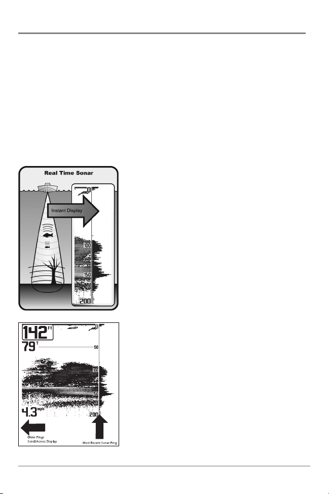
SONAR is an acronym for SOund and NAvigation Ranging.
Sonar utilizes precision sound pulses or "pings" which are
emitted into the water in a teardrop-shaped beam.
The sound pulses "echo" back from objects in the water such
as the bottom, fish and other submerged objects. The
returned echoes are displayed on the LCD screen. Each time
a new echo is received, the old echoes are moved across the
LCD, creating a scrolling effect.
When all the echoes are viewed side by side, an easy to
interpret "graph" of the bottom, fish and structure appears.
1
2
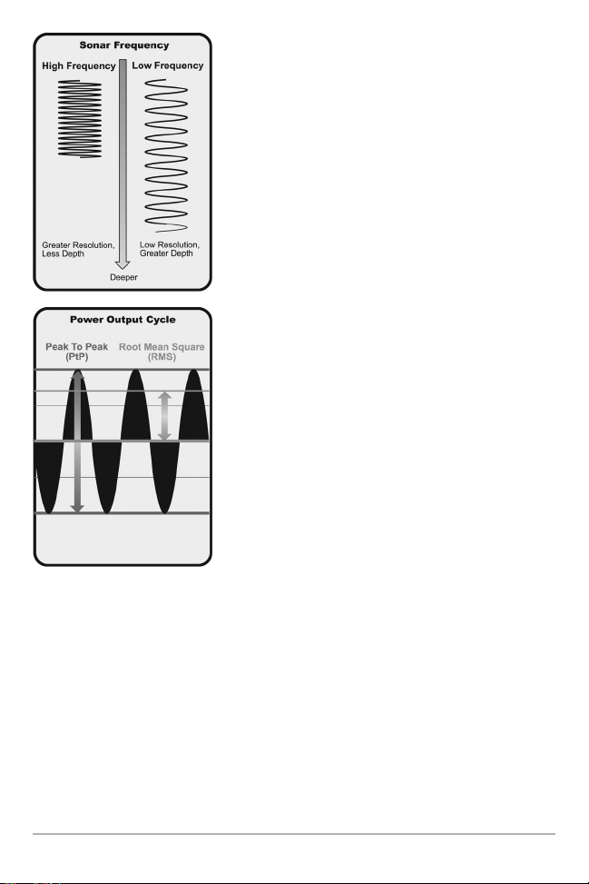
The sound pulses are transmitted at various frequencies
depending on the application. Very high frequencies (455kHz)
are used for greatest definition but the operating depth is
limited. High frequencies (200kHz) are commonly used on
consumer sonar and provide a good balance between depth
performance and resolution. Low frequencies (83kHz) are
typically used to achieve greater depth capability.
The power output is the amount of energy generated by the
sonar transmitter. It is commonly measured using two
methods:
• Root Mean Square (RMS) measures power output over
the entire transmit cycle.
• Peak to Peak measures power output at the highest
points.
The benefits of increased power output are the ability to
detect smaller targets at greater distances, ability to
overcome noise, better high speed performance and
enhanced depth capability.
3
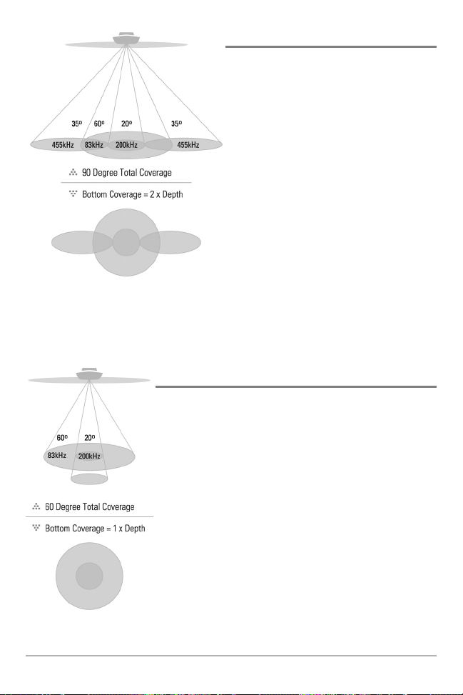
QuadraBeam PLUS™ Sonar
Your 700 Series™ Fishing System supports
QuadraBeam PLUS™ sonar. QuadraBeam
PLUS™ sonar provides an extremely wide 90°
area of coverage. QuadraBeam PLUS™ starts
with two fan-shaped 35° 455 kHz Side
Structure locating sonar beams to spot fish,
bait and structure to the left and right of the
boat over an area of the bottom that’s always
equal to twice your depth. For a detailed view
below the boat, QuadraBeam PLUS™ uses
DualBeam PLUS™ technology, with precision
20° and wide 60° beams. QuadraBeam PLUS™
finds more fish faster, and can even tell you
where to put your bait by showing if fish are to
the left, right or directly beneath your boat.
DualBeam PLUS™ Sonar
Your 700 Series™ Fishing System uses a 200/83 kHz DualBeam
PLUS™ sonar system with a wide (60°) area of coverage.
DualBeam PLUS™ sonar has a narrowly focused 20° center beam,
surrounded by a second beam of 60°, expanding your coverage
to an area equal to your depth. In 20 feet of water, the wider
beam covers an area 20 feet wide. The 20° center beam is
focused on the bottom, to show you structure, weeds and cover.
The 60° wide beam is hunting for fish in the wide coverage area.
DualBeam PLUS™ sonar returns can be blended together, viewed
separately or compared side-by-side. DualBeam PLUS™ is ideal for
a wide range of conditions - from shallow to very deep water in
both fresh and salt water. Depth capability is affected by such
factors as boat speed, wave action, bottom hardness, water
conditions and transducer installation.
4
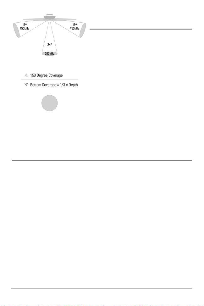
WideSide® Sonar
(with optional-purchase WideSide® transducer)
Your 700 Series™ Fishing System also supports
WideSide® sonar with the purchase of an additional
WideSide® transducer. The WideSide® transducer is a
specialized "side-looking" transducer that is extremely
useful for bank fishing or looking for bait fish in open
water. The WideSide® transducer uses three different
sonar elements that transmit signals to the left, right
and straight down from your boat. The downward
beam is 200 kHz with a 24° area of coverage. This
beam maintains a continuous digital depth readout
from the bottom directly beneath your boat. The side
beams are 455 kHz with a 16° area of coverage. The
side-looking elements can be used independently, or
together to locate targets near the surface of the water
on either side of your boat.
Universal Sonar 2
Your 700 Series™ Fishing System supports Universal Sonar 2, a state-of-the-art, integrated
and protected transducer that is built into the lower unit of Minnkota trolling motors. With
Universal Sonar 2, all wiring is concealed inside the indestructible composite shaft—out of
sight and out of harm’s way, with no clamps, ties, or exposed wires. Universal Sonar 2
features new temperature sensing and the performance of DualBeam PLUS™ technology
(available with all Humminbird® DualBeam PLUS™ models). An expanded view and greater
bottom detail gives you a totally new perspective of the water below, along with optimal
sonar performance to help you find fish.

5
How GPS and Cartography Work
(with optional-purchase GPS Receiver)
With the purchase of an additional GPS Receiver, your 700 Series™ Fishing System also
supports GPS and chartplotting. With a GPS Receiver, your 737 uses GPS and sonar to
determine your position, display it on a grid, and provide detailed underwater information.
The Global Positioning System (GPS) is a satellite navigation system designed and
maintained by the U.S. Department of Defense. GPS was originally intended for military use;
however, civilians may also take advantage of its highly accurate position capabilities,
typically within +/- 10 meters, depending on conditions. This means that 95% of the time, the
GPS receiver will read a location within 10 meters of your actual position. Your GPS Receiver
also uses information from WAAS (the Wide Area Augmentation System), EGNOS (the
European Geostationary Navigation Overlay Service), and MSAS (the MTSAT Satellite
Augmentation System) satellites if they are available in your area.
GPS uses a constellation of 24 satellites that continually send
radio signals to the earth. Your present position is determined
by receiving signals from up to 16 satellites and measuring
the distance from the satellites.
All satellites broadcast a uniquely coded signal once per
second at exactly the same time. The GPS receiver on your
boat receives signals from satellites that are visible to it.
Based on time differences between each received signal, the
GPS receiver determines its distance to each satellite. With
distances known, the GPS receiver mathematically
triangulates its own position. With once per second updates,
the GPS receiver then calculates its velocity and bearing.
The optional-purchase GPS Receiver, when used with your 700 Series™ Fishing System, allows
you to combine easy-to-use FishingGPS™ chartplotter and navigation capabilities with advanced
fishfinding. The following GPS functionality is currently supported by the 700 Series™ Fishing
System when it is connected to the optional-purchase GPS receiver.
• View current position
• View current track (breadcrumb trail)
• View precision speed and heading from your GPS receiver
• Save tracks, waypoints and routes
• Travel a route and navigate from one waypoint to the next.
6
Your 700 Series™ supports Navionics® Gold, HotMaps™ and HotMaps™Premium on MMC or SD
card media.
NOTE: Your 700 Series™ does not support Navionics® Classic Charts, only Navionics® Gold,
HotMaps™, and HotMaps™ Premium.
Your unit also comes with a built-in World map.
Your 700 Series™ uses the optional-purchase GPS Receiver to determine the position of the boat
automatically, and uses the zoom level settings on a particular view to select the best chart to
display. See Viewing Cartography for more information.
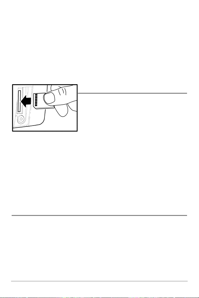
Multi-Media Card (MMC)/SD Slot
Your 700 Series™ Fishing System also has a multi-media
card (MMC)/SD slot that is used to insert optionalpurchase cards containing additional detailed maps.
NOTE: MMC/SD cards require an optional-purchase GPS
receiver in order to function.
If you insert an MMC/SD that contains a more detailed chart for a particular location, your
700 Series™ Fishing System will retrieve that chart and display it automatically. Use the
illustration to locate the position of the MMC/SD slot cover, remove the MMC/SD slot cover,
then insert the MMC/SD into the slot. The label on the MMC/SD should face toward the right
side of the unit. Press down on the card until it clicks into place, then replace the slot cover,
making certain that the gasket is present and positioned correctly before re-installing the
cover, then replace and tighten snugly - do NOT overtighten, as this will not improve water
resistance, and may damage the cover.
Software Updates
Use the MMC/SD slot to update the software version of your control head. To update the
software in your control head, plug in the appropriate MMC/SD card that contains a software
update file; the unit will recognize it, will tell you what software version your control
head is currently running, and will ask you if you want to update the software in the unit
to match that on the MMC/SD card. You can obtain software updates from the
www.humminbird.com website.
Inserting an MMC/SD into the Card Slot
7
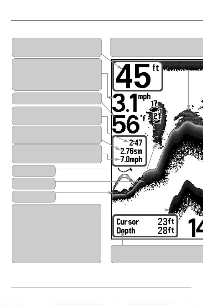
What’s On the Display
The 700 Series™ Fishing System can display a variety of useful information about the area
NOTE: Entries in this view that list (with Temp/Speed or GPS Receiver) are available if either
connected, then only the information from the GPS receiver will be displayed on the view.
Timer - elapsed time with Temp/Speed
Accessory or GPS Receiver.
Average Speed - average speed reading with
Temp/Speed Accessory or GPS Receiver.
Depth - water depth; can be set to alarm
when the water becomes too shallow.
Speed - if a Temp/Speed accessory or GPS
Receiver is attached, the 700 Series™ can
display the speed of the boat, and can keep a
Triplog of nautical or statute miles traveled.
Second Sonar Return - when the sonar
signal bounces between the bottom and the
surface of the water and back again. Use the
appearance of the second return
to determine bottom hardness. Hard
bottoms will show a strong second return,
while soft bottoms will show a very weak one
or none at all.
Cursor Dialog Box - indicates cursor depth
bottom directly below the cursor.
Bait Ball
Hard Bottom
Rocky Bottom
Cursor - available in Freeze Frame and can
provide depth of a sonar return and bottom
Distance - distance traveled with Temp/Speed
Accessory or GPS Receiver.
Temperature - water surface temperature.
8
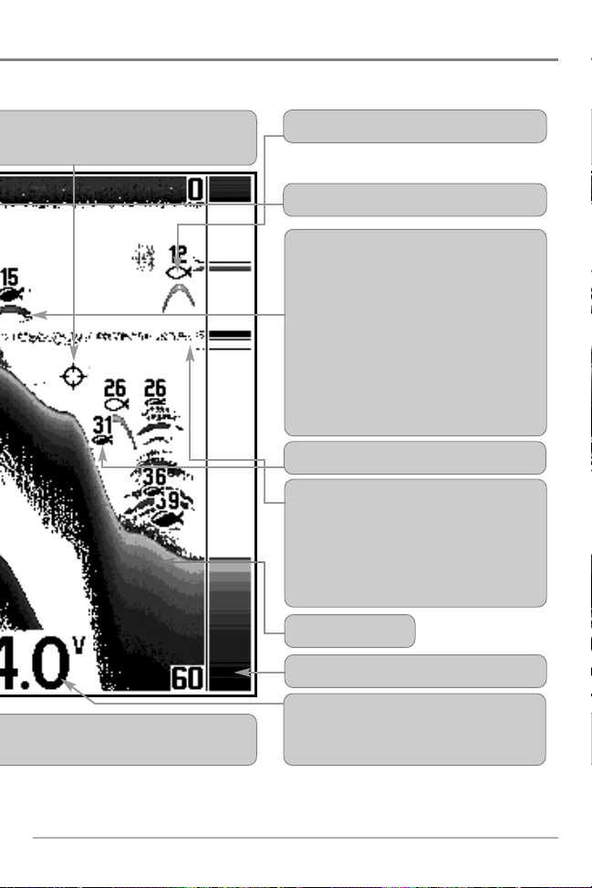
under and adjacent to your boat, including the following items:
optional-purchase device is connected to the 700 Series™ Fishing System. If both devices are
on the display and the depth of the
Battery Voltage - the voltage of the boat’s
battery; can be set to alarm if the voltage falls
below a certain point.
RTS® (Real Time Sonar) Window
Soft Bottom
Thermoclines - layers of water with different
temperatures that appear at different depths
and different times of the year. A thermocline
typically appears as a continuous band of
many gray levels moving across the display at
the same depth.
Structure - where fish may be hiding.
Fish - fish are displayed as arches and/or fish
icons, and the unit can be set to alarm when a
fish of a certain size is detected. When a target
is detected and Fish ID+ is on, a Fish ID+
TM
symbol with depth is displayed. The size of
the symbol shows the intensity of the sonar
return. The unit will clearly show schools of
Bait Fish as "clouds" of different shapes and
sizes, depending on the number of fish and
boat speed.
be positioned in the Sonar View to
depthbelow the cursor.
83 kHz, Wide Beam Hollow Fish Symbol
200 kHz, Narrow Beam Shaded Fish Symbol
9
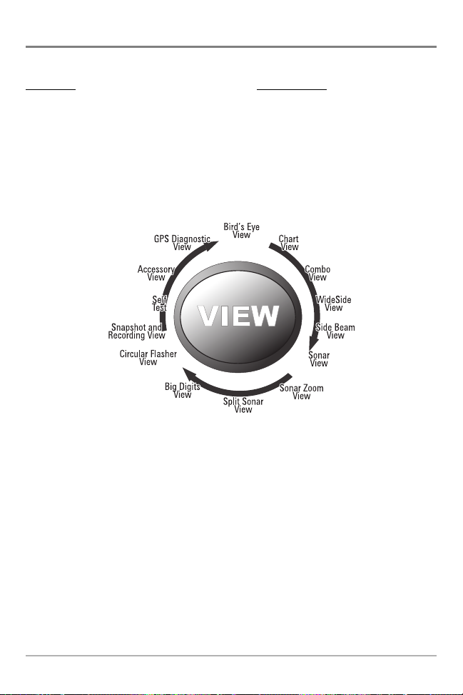
Views
The views available on your 700 Series™ Fishing System are:
Sonar views: Navigation views:
• Sonar View • Bird’s Eye View
• Zoom View • Chart View
• 200/83 kHz Split Sonar View • Combo View
• Big Digits View
• Circular Flasher View
• Snapshot and Recording View
• Side Beam View
• WideSide® View(with optional-purchase WideSide® transducer
NOTE: When you change any menu settings that affect the sonar, the view will update
immediately (i.e. you don’t have to exit the menu to apply the change to the screen). For instance,
by switching between "Inverse" and "Structure ID®" from the X-Press
TM
Menu it is possible to quickly
alternate between the two viewing methods.
NOTE: WideSide® View requires the purchase of the WideSide® transducer. You can visit our
website at www.humminbird.com to order accessories online or contact our Customer Resource
Center at 1-800-633-1468.
NOTE: Navigation views require the purchase of the GPS Receiver. You can visit our website at
www.humminbird.com to order these accessories online or contact our Customer Resource Center
at 1-800-633-1468.
Sonar View is the default view. When the VIEW key is pressed, the display cycles through the
available views. When the EXIT key is pressed, the display cycles through the available views
in reverse order. Any view can be hidden or displayed as part of the view rotation using the
Views Menu tab.
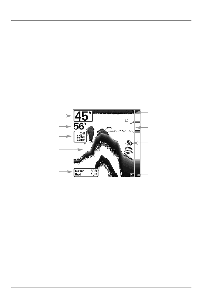
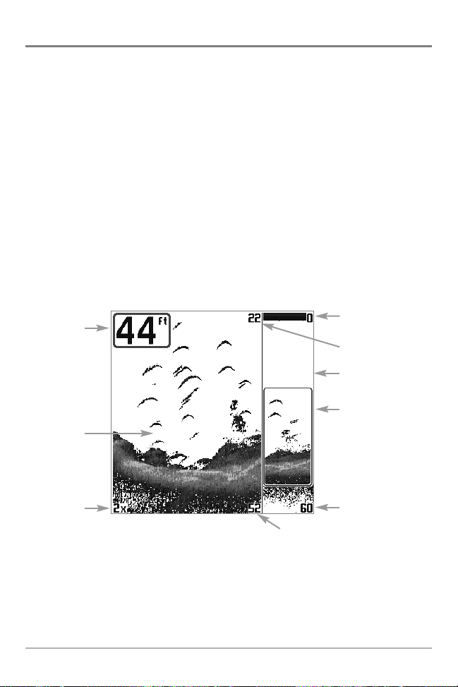
Sonar View
Sonar View presents a historical log of sonar returns. Depth is always displayed. Readouts for
temperature and speed are automatically displayed if the appropriate accessory is connected. The
most recent sonar returns are charted on the right side of the window; as new information is
received, the older information is moved across the display to the left. A Digital Depth Readout is
displayed in the upper left corner. A scale with Upper and Lower Depth Range readouts appears
along the right edge of the Sonar View. The scale indicates the distance from the surface of the
water to a depth range sufficient to show the bottom. Depth Range is automatically selected to
keep the bottom visible on the display, although you can adjust it manually as well (see Sonar
X-Press
TM
Menu). Six additional Digital Readouts display information from optional-purchase
accessories. These information boxes can be customized to show only the information desired
(see Setup Menu Tab, Select Readouts).
NOTE: If the Depth number is flashing, it means that the unit is having trouble locating the bottom.
This usually happens if the water is too deep, the transducer is out of the water, the boat is moving
too fast, or for any other reason that the unit can’t accurately receive continuous data.
Sonar View
Upper Depth
Range
Sonar History
Window
Depth
Cursor Dialog Box
Temperature
Triplog
Lower Depth
Range
RTS® Window
Cursor
10
11
Understanding Sonar History
It is important to understand the significance of the 700
Series™ Fishing System display. The display does NOT show a
literal 3-dimensional representation of what is under the water.
Each vertical band of data received by the control head and
plotted on the display represents something that was detected
by a sonar return at a particular time. As both the boat and the
targets (fish) may be moving, the returns are only showing a
particular segment of time when objects were detected, not
exactly where those objects are in relation to other objects
shown on the display.
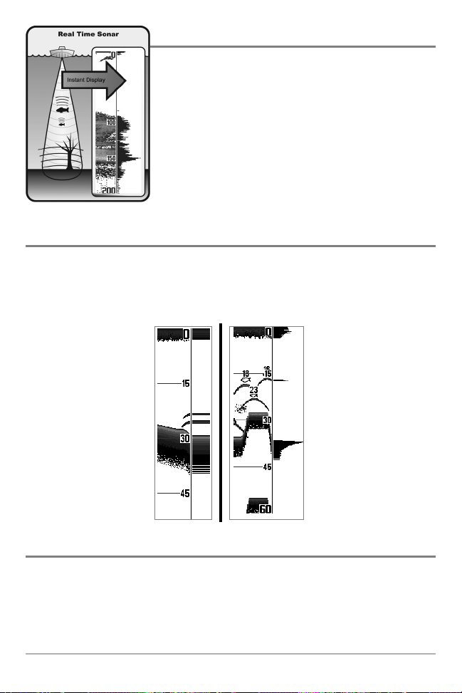
Real Time Sonar (RTS®) Window
A Real Time Sonar (RTS®) Window appears on the right side of the display in the Sonar View only.
The RTS® Window always updates at the fastest rate possible for depth conditions and shows only
the returns from the bottom, structure and fish that are within the transducer beam. The RTS®
Window plots the depth and intensity of a sonar return (see Sonar Menu - RTS® Window).
Freeze Frame
Freeze Frame - Pressing any arrow on the 4-WAY Cursor Control key will freeze the screen and a
cursor will be displayed on the screen. The cursor can be positioned on the display using the
4-WAY Cursor Control key to determine the depth of any sonar return. The RTS® Window
continues to update in Freeze Frame. In addition, see the effects of menu setting changes with
Instant Image Update. Pressing EXIT will exit Freeze Frame and the display will start to scroll.
Freeze Frame is available in the Sonar, Sonar Zoom, and 200/83 kHz Split Sonar Views.
The Narrow RTS® Window
indicates the sonar intensity
through the use of grayscale.
The grayscale used matches
the bottom view grayscale
setting used in the sonar
history window (i.e. Inverse,
Structure ID®, WhiteLine®,
Bottom Black). The depth of
the sonar return is indicated
by the vertical placement of
the return on the display
depth scale.
The Wide RTS® Window
indicates the sonar intensity
through the use of a bar
graph. The length of the
plotted return provides an
indication of whether the
return is weak or strong. The
depth of the sonar return is
indicated by the vertical
placement of the return on
the display depth scale. The
Wide RTS® Window does not
make use of grayscale.
12
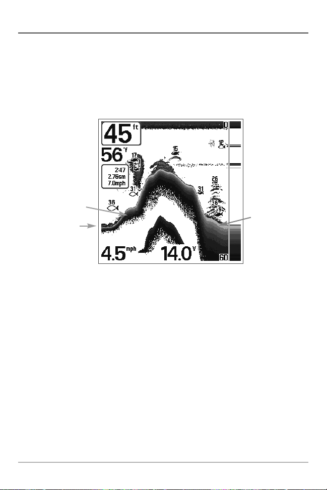
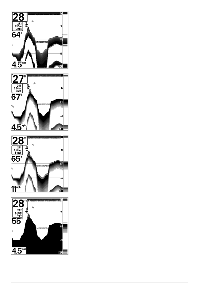
Bottom Presentation
As the boat moves, the unit charts the changes in depth on the display to create a profile of the
Bottom Contour. The type of bottom can be determined from the return charted on the display. A
Hard Bottom such as compacted sediment or flat rock appears as a thinner line across the display.
A Soft Bottom such as mud or sand appears as a thicker line across the display. Rocky Bottoms
have a broken, random appearance.
The sonar returns from the bottom, structure and fish can be represented as either Inverse
(default), WhiteLine®, Structure ID®, or Bottom Black. See Sonar X-Press
TM
Menu: Bottom View for
details on how to set the bottom view.
Bottom Contour Profile with RTS® Window.
Temp/Speed Accessory is optional.
Rocky Bottom
Hard Bottom
Soft Bottom
13
Inverse is a method where weak returns are shown with dark
pixels and strong returns with lighter pixels. This has the benefit
of ensuring that weak signals will be clearly visible on the
display.
Structure ID® represents weak returns as light pixels and strong
returns as dark pixels. This has the benefit of ensuring that
strong returns will be clearly visible on the display.
WhiteLine® highlights the strongest sonar returns in white,
resulting in a distinctive outline. This has the benefit of clearly
defining the bottom on the display.
Bottom Black displays all pixels below the bottom contour as
black, regardless of signal strength. This has the benefit of
providing a high contrast between the bottom and other sonar
returns on the display. Any targets such as fish, structure and
thermoclines will be shown using the Structure ID® method.
14
Sonar Zoom View
Sonar Zoom View increases the displayed resolution to separate sonar returns that are very close
together, such as those caused by fish suspended close to the bottom or within structure. In Zoom
View, the display is split to show a narrow slice of the full range view on the right and the zoomed
view on the left. The full range view on the right also contains the Zoom Preview Box that shows
what part of the full range view is shown in zoom view on the left; the Zoom Preview Box tracks
the bottom in the full range view.
As the depth changes, the zoomed view updates automatically to display a magnified image of
the bottom. The Zoom Preview Box shows where the zoomed view is in relation to the full range
view. The Zoom Level, or magnification, is displayed in the lower left corner and can be changed
to suit conditions (see Sonar X-Press
TM
Menu: Zoom Level). Upper and Lower Zoom Depth Range
numbers indicate the depth of the water which is being viewed.
Digital depth is displayed in the upper left hand corner. The digital readouts in the Sonar Zoom
View cannot be customized; therefore, information such as water temperature and voltage are
unavailable in the Sonar Zoom View.
Sonar Zoom View
Full Range View
Upper Depth Range,
Full Range View
Lower Depth
Range, Zoom View
Lower Depth Range,
Full Range View
Zoomed
View
Zoom
Preview Box
Zoom Level
Depth
Upper Depth Range,
Zoom View
15
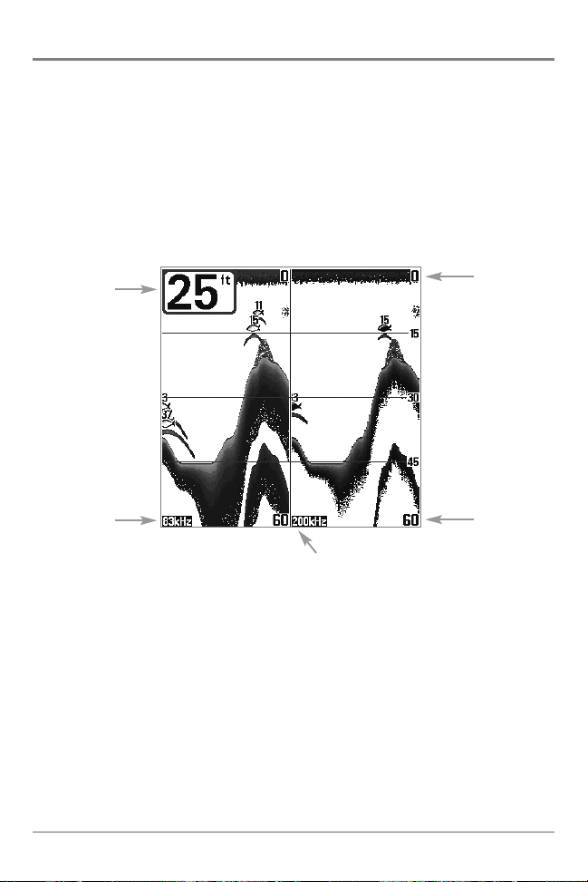
200/83 kHz Split Sonar View
Split Sonar View displays sonar returns from the 83 kHz wide beam on the left side of the screen
and displays sonar returns from the 200 kHz narrow beam on the right side of the screen. Depth
is always displayed in the upper left hand corner. You can use the Split Sonar View to make side
by side comparisons between the sonar returns from the 83 kHz wide beam and the 200 kHz
narrow beam.
The digital readouts in the Split Sonar View cannot be customized; therefore, information such as
water temperature and voltage are unavailable in the Split Sonar View.
200/83 kHz Split Sonar View
Depth
83 kHz
Sonar History
Window
200 kHz
Sonar History Window
Upper
Depth Range
Lower
Depth Range
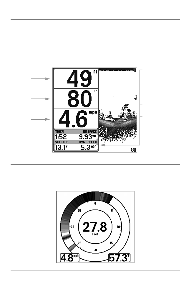
Big Digits View
Big Digits View provides digital data in a large, easy-to-see format. Depth is always displayed.
Readouts for temperature, speed and Triplog information are displayed automatically if the
appropriate accessory is connected to the system. The Triplog shows distance traveled, average
speed, and time elapsed since the Triplog was last reset. The digital readouts in the Big Digits View
cannot be customized.
Circular Flasher View
Circular Flasher View displays Real Time Sonar (RTS®) data in the traditional flasher format. Depth
and temperature are always displayed. The digital readouts in the Flasher View cannot be
customized.
Big Digits View
Depth
Temperature
Speed
Timer shows the time
elapsed since Triplog
was last reset
Distance is the distance
traveled since the
Triplog was last reset
Voltage - the battery
voltage.
Average Speed shows
the speed since the
Triplog was last reset
16
17
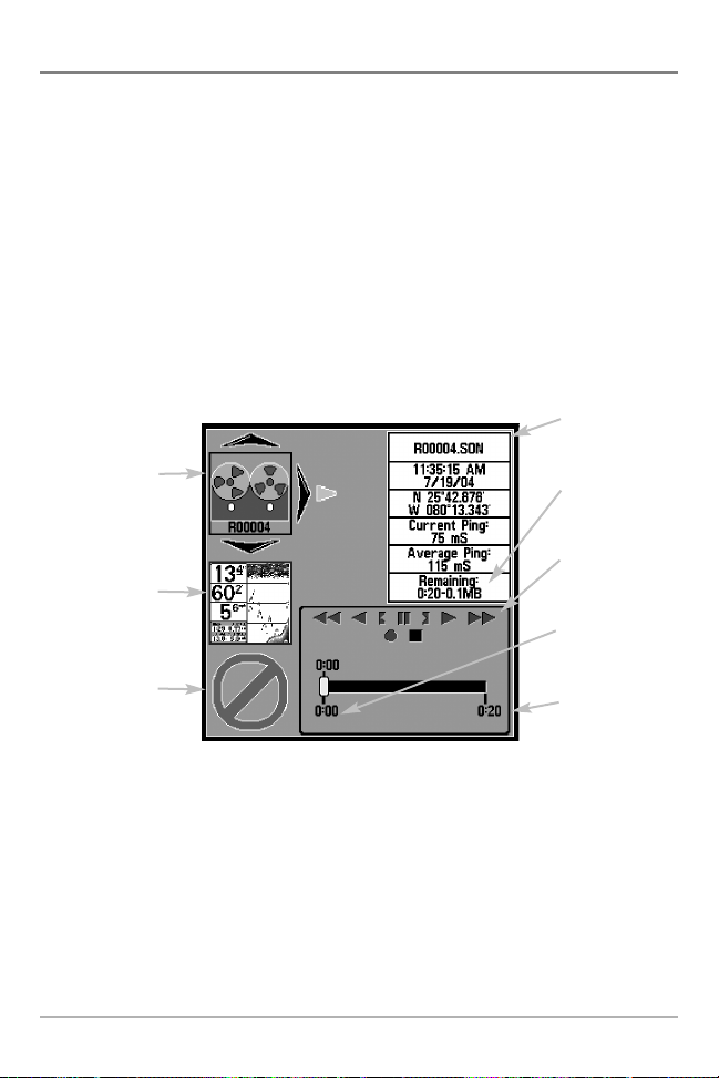
Snapshot and Recording View
Snapshot and Recording View displays and allows you to view both screen snapshot
thumbnails and recording icons captured to an optional-purchase MMC/SD card installed in
your unit. In addition, when you are in the Snapshot and Recording View, Start Recording,
Stop Recording, Delete Image, Delete All Images, Delete Recording, Delete All Recordings,
Pings Per Second, Playback Speed and Stop Playback are added to the X-Press™ menu.
The Snapshot and Recording View displays up to three screen snapshot thumbnails or
recording icons on the screen at a time; you may have to scroll using the 4-WAY Cursor keys
to see the whole list of thumbnails and/or icons in this view. The selected thumbnail or icon
will be highlighted with arrows.
NOTE: The speed of the screen capture or of the recording depends on the type of card you use; in
general, SD cards capture the screen faster than MMC cards do.
NOTE: For snapshots and recordings, the indicator bar has several states: during recording, the
amount of space remaining on the MMC/SD card is indicated on the status bar. During
playback, the amount of time/memory remaining to play is indicated on the status bar. When
a snapshot thumbnail is highlighted, the amount of room remaining on the MMC/SD card is
indicated.
Snapshot and Recording View
Amount of space
used for this
recording
Information Box
Amount of
recording left
to play
Amount of
recording that
has been played
Snapshot
thumbnail
Recording icon
Unavailable icon
Recording
mode icons

Screen Snapshot: When Screen Snapshot is enabled (from the Accessories menu tab),
pressing the MARK key creates a saved screen capture (when you have an optional-purchase
MMC/SD card installed). Once you have created a screen capture, a screen capture thumbnail
is added to the Snapshot and Recording View, and is available to view at a later date. See the
full-sized image by highlighting a thumbnail (using the Up or Down 4-Way Cursor keys), then
using the Right 4-Way Cursor key to view the full image. A border around the full-size screen
snapshot indicates that it is just a screen snapshot, not a “live” view. You can delete the
selected image, or all images, by selecting a thumbnail and using Delete Image, or using
Delete All Images from the Snapshot and Recording X-Press™ menu.
Working with screen snapshots is a four-step process:
1. Enabling Screen Snapshot from the Accessories Menu.
2. Making a Screen Snapshot using the MARK key.
3. Viewing a Screen Snapshot using the Snapshot and Recording View.
4. Deleting a Screen Snapshot using the Snapshot and Recording X-Press™ menu.
For more information, see Accessories Menu Tab: Using Screen Snapshot and Snapshot and
Recording X-Press™ Menu.
When you start a screen snapshot, you will see a message that a waypoint has been created
at the point where your cursor is on the screen, and the screen will freeze while the snapshot
is being saved to the MMC/SD card. A status dialog box will appear that shows the progress
of the save as a percentage, and that displays the numbered file name assigned to the .BMP
file that is being created. Snapshot filenames begin with the letter "S". For more information,
see Accessories Menu Tab: Using Screen Snapshot procedure and Snapshot and Recording
X-Press™ Menu.
18

19
Recording and Playback: From the Snapshot and Recording View, you can use the X-Press™
menu to start and stop recording, and to change the pings per second (which alters the detail
level of the recording). Once you are recording already, playing back a recording and screen
snapshot viewing are not allowed, and the only Sonar Recording menu choices available in the
X-Press™ menu are Stop Recording and Pings Per Second. Use the 4-Way Cursor keys from the
Snapshot and Recording View to start playback of a specific recording icon. You can then cycle
through all the views using the VIEW key to see what those views looked like during the
recorded time period. You can also use the X-Press™ menu to change playback speed, stop
playback, and delete recording icons.
Working with sonar recordings is a six-step process:
1. Displaying the Snapshot and Recording View.
2. Starting a sonar recording using the Snapshot and Recording X-Press™ menu.
3. Changing the maximum ping rate for the recording using the Snapshot and
Recording X-Press™ menu (optional).
4. Stopping a recording using the Snapshot and Recording X-Press™ menu.
5. Playing back a recording, using the Snapshot and Recording View and the 4-Way
Cursor keys, and changing the playback speed using the Snapshot and Recording XPress™ menu.
6. Deleting a recording using the Snapshot and Recording X-Press™ menu.
For more information, see Snapshot and Recording X-Press™ Menu.
When you start a sonar recording, you will see a message that a waypoint has been created
at your current location. During recording, playing back a recording and screen snapshot
viewing are not allowed. An information box displays a variety of information including the
numbered file name assigned to the .SON file that is being created. The slider bar at the
bottom of the screen shows the progress of the recording as well as how much space is
remaining on the MMC/SD card.
NOTE: The waypoints that are created by a recording have the same name as the file and use a
custom waypoint icon. Recording filenames begin with the letter "R".
For more information, see Snapshot and Recording X-Press™ Menu.
Highlighting a recording: You can scroll through the whole list of recording icons available in
the Snapshot and Recording View using the 4-WAY Cursor keys. The highlighted icon will be
surrounded by arrows, and a green play triangle will appear to its right.
Playing back a recording: Highlight a recording icon (using the Up or Down 4-Way Cursor
keys), then use the Right 4-Way Cursor key to start playback. During playback, all active
navigation is cancelled, all other thumbnails and icons will disappear, and a "Playback"
message box similar to the Simulation message will be displayed periodically. When playback
begins, the view is automatically switched to the primary Sonar View for your model, and no
live sonar data will be displayed; only recorded sonar and GPS data will be shown, and the
Snapshot and Recording View will display the playback status. You can change the speed, skip
to the beginning or end of playback, and even reverse playback, using the Playback Speed XPress™ menu item, and stop the playback using the Stop Playback X-Press™ menu item; these
items are added to the X-Press™ menus in all views during playback. In the Snapshot and
Recording View only, playback speed can also be changed using the Left and Right 4-Way
Cursor keys. Playback is paused when the sonar cursor is active and resumes playing when the
cursor is removed. Playback is automatically paused when the end of the recording is reached.
NOTE: Sonar chart speed is increased during Fast Forward and reversed during Rewind. This may
reduce the quality of the sonar image, since at higher speeds, not every sonar return can be
processed and displayed.
NOTE: Navigation is not affected by the Sonar Recording feature, but any active navigation is
cancelled when playback begins or ends.
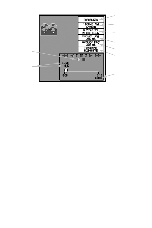
Recording Slider Bar
Recording
Indicator
Amount of
space and time
used by
this recording
Name of recording
Time and Date
recording was started
Position where
recording was started
Current Ping Rate
Average Ping Rate
Amount of space
remaining on card
Total amount of
space on card
20
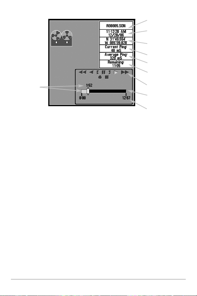
You can delete the highlighted recording, or all recordings, using Delete Recording or Delete All
Recordings from the Snapshot and Recording X-Press™ menu.
Recording Playback
Amount of Time
Already Played
Name of recording
Time and Date
recording started
Position when
recording started
Current Ping Rate
Average Ping Rate
Amount of time
remaining to play
Playback speed icons
Amount of time
remaining to play
Overall length of
recording
21
 Loading...