

Humminbird 67 User Manual
531296-1_A
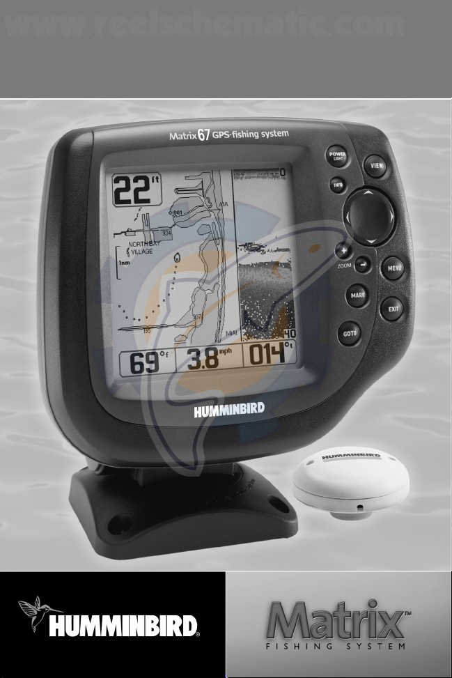
Matrix 67 GPS Trackplotter
Operations Manual
Matrix 67 GPS Trackplotter
Operations Manual
www.reelschematic.com
www.reelschematic.com

i
Thank You!
Thank you for choosing Humminbird®, America's #1 name in fishfinders. Humminbird® has built its
reputation by designing and manufacturing top-quality, thoroughly reliable marine equipment. Your
Humminbird® is designed for trouble-free use in even the harshest marine environment. In the
unlikely event that your Humminbird® does require repairs, we offer an exclusive Service Policy - free
of charge during the first year after purchase, and available at a reasonable rate after the one-year
period. For complete details, see the separate warranty card included with your unit. We encourage
you to read this operations manual carefully in order to get full benefit from all the features and
applications of your Humminbird® product.
Contact our Customer Resource Center at either 1-334-687-0503 or visit our website at
www.humminbird.com.
WARNING! This device should not be used as a navigational aid to prevent collision, grounding, boat
damage, or personal injury. When the boat is moving, water depth may change too quickly to allow
time for you to react. Always operate the boat at very slow speeds if you suspect shallow water or
submerged objects.
WARNING! Disassembly and repair of this electronic unit should only be performed by authorized
service personnel. Any modification of the serial number or attempt to repair the original equipment
or accessories by unauthorized individuals will void the warranty. Handling and/or opening this unit
may result in exposure to lead, in the form of solder.
WARNING! This product contains lead, a chemical known to the state of California to cause cancer,
birth defects and other reproductive harm.
Humminbird®, HumminbirdPCTM, DualBeam PLUSTM, QuadraBeamTM, Selective Fish ID+TM,
WhiteLine®, RTS® Window, X-Press
TM
Menu, Fish ID+TM, Fishing GPSTM, Structure ID®, and
WeatherSense
TM
are trademarked by or registered trademarks of Techsonic Industries, Inc.
© 2003 Techsonic Industries, Inc., Eufaula AL, USA. All rights reserved.
www.reelschematic.com
www.reelschematic.com
ii
How Sonar Works 1
DualBeam PLUS™ Sonar ................................................................................................................................................ 1
QuadraBeam™ Sonar (With Optional-Purchase QuadraBeam™ Transducer) .................................................. 1
WideSide Sonar (With Optional-Purchase WideSide Transducer)...................................................................... 2
How GPS and Cartography Work 2
Multi-Media Card (MMC) .............................................................................................................................................. 3
What’s On the Sonar Display 4
Views 6
Sonar View........................................................................................................................................................................ 7
Understanding Sonar History ...................................................................................................................................... 8
Real Time Sonar (RTS®) Window ................................................................................................................................ 8
Bottom Presentation...................................................................................................................................................... 9
Sonar Zoom View ................................................................................................................................................................ 11
200/83 kHz Split Sonar View .................................................................................................................................... 12
Big Digits View .............................................................................................................................................................. 12
Side Beam View ............................................................................................................................................................ 13
WideSide View .............................................................................................................................................................. 14
Bird's Eye View .............................................................................................................................................................. 15
Chart View ...................................................................................................................................................................... 16
Combo View .................................................................................................................................................................. 17
View Orientation .......................................................................................................................................................... 17
Viewing Cartography 17
Introduction to Navigation 19
Waypoints, Routes and Tracks .................................................................................................................................. 19
Save, Edit or Delete a Waypoint .............................................................................................................................. 20
Navigate to a Waypoint or Position ........................................................................................................................ 21
Add a Waypoint Target or Trolling Grid.................................................................................................................. 22
Save, Edit or Delete a Route ...................................................................................................................................... 23
Save or Clear a Current Track .................................................................................................................................... 24
Edit, Delete or Hide Saved Tracks ............................................................................................................................ 24
Key Functions 25
POWER/LIGHT Key ...................................................................................................................................................... 25
VIEW Key ........................................................................................................................................................................ 25
INFO Key.......................................................................................................................................................................... 25
MENU Key ...................................................................................................................................................................... 26
4-WAY Cursor Control Key ........................................................................................................................................ 26
MARK Key ...................................................................................................................................................................... 26
GOTO Key........................................................................................................................................................................ 27
Table of Contents
www.reelschematic.com
www.reelschematic.com
ZOOM (+/-) Key ............................................................................................................................................................ 27
EXIT Key .......................................................................................................................................................................... 27
Accessory Bus 28
Powering Up the Unit 28
The Menu System 29
Start-Up Options Menu 31
Normal Operation ........................................................................................................................................................ 31
Simulator ...................................................................................................................................................................... 31
System Status .............................................................................................................................................................. 32
PC Connect (with PC Connect Cable Only) .............................................................................................................. 33
Sonar X-Press™ Menu (Sonar Views Only) 34
WideSide View (WideSide Transducer: WideSide View Only).......................................................................... 34
Sensitivity ...................................................................................................................................................................... 35
Upper Range (Advanced: Sonar, Split Sonar and Big Digits Views Only) ...................................................... 36
Lower Range .................................................................................................................................................................. 37
Side Beam Range (WideSide Transducer: WideSide View Only)...................................................................... 38
Chart Speed .................................................................................................................................................................. 38
Bottom View.................................................................................................................................................................. 39
Zoom Level (Sonar Zoom View Only) ...................................................................................................................... 39
Navigation X-Press™ Menu (Navigation Views Only) 40
Save Current Track ...................................................................................................................................................... 40
Clear Current Track ...................................................................................................................................................... 40
Save Current Route (Only When Navigating) ........................................................................................................ 41
Skip Next Waypoint (Only When Navigating) ...................................................................................................... 41
Cancel Navigation (Only When Navigating) .......................................................................................................... 41
Remove Target (Only If Target is Active) .............................................................................................................. 42
Remove Grid (Only If Grid is Active) ........................................................................................................................ 42
Sonar Window (Combo View Only) ........................................................................................................................ 42
Sonar Menu Tab 43
Beam Select ..................................................................................................................................................................44
Fish ID+
TM
........................................................................................................................................................................ 45
Fish Sensitivity .............................................................................................................................................................. 46
Real Time Sonar (RTS®) Window.............................................................................................................................. 46
83 kHz Sensitivity (Advanced) .................................................................................................................................. 46
455 kHz Balance (Advanced, with QuadraBeam
TM
Transducer) ........................................................................ 47
WideSide Sensitivity (Advanced, with WideSide Transducer) .......................................................................... 47
Depth Lines (Advanced).............................................................................................................................................. 48
Surface Clutter (Advanced) ........................................................................................................................................ 49
Table of Contents
iii
www.reelschematic.com
www.reelschematic.com

iv
Noise Filter (Advanced) .............................................................................................................................................. 50
Max Depth (Advanced) .............................................................................................................................................. 50
Water Type (Advanced) .............................................................................................................................................. 51
Transducer Select .......................................................................................................................................................... 51
Navigation Menu Tab 52
Tracks .............................................................................................................................................................................. 53
Waypoints ...................................................................................................................................................................... 54
Routes .............................................................................................................................................................................. 55
View Orientation .......................................................................................................................................................... 55
Chart Detail Level.......................................................................................................................................................... 56
Map Borders .................................................................................................................................................................. 56
Lat-Lon Grid .................................................................................................................................................................... 57
Spot Soundings.............................................................................................................................................................. 57
North Reference ............................................................................................................................................................ 57
Grid Rotation.................................................................................................................................................................. 57
Trackpoint Interval ...................................................................................................................................................... 58
Track Min Distance (Advanced) ................................................................................................................................ 58
Map Datum (Advanced).............................................................................................................................................. 59
Set Simulation Position (Advanced) ........................................................................................................................ 59
Set Map Offset (Advanced) ........................................................................................................................................ 59
Clear Map Offset (Advanced) .................................................................................................................................... 60
Delete All Nav Data (Advanced) .............................................................................................................................. 60
Alarms Menu Tab 61
Depth Alarm .................................................................................................................................................................. 62
Fish ID Alarm.................................................................................................................................................................. 62
Low Battery Alarm........................................................................................................................................................ 63
Off Course Alarm .......................................................................................................................................................... 63
Arrival Alarm.................................................................................................................................................................. 64
Drift Alarm .................................................................................................................................................................... 64
Alarm Tone .................................................................................................................................................................... 64
Setup Menu Tab 65
Units - Depth.................................................................................................................................................................. 66
Units - Temp (International Only) ............................................................................................................................ 66
Units - Distance ............................................................................................................................................................ 66
Units - Speed .................................................................................................................................................................. 67
User Mode ...................................................................................................................................................................... 67
Language (International Only) .................................................................................................................................. 67
Triplog Reset ................................................................................................................................................................ 68
Restore Defaults .......................................................................................................................................................... 68
Table of Contents
www.reelschematic.com
www.reelschematic.com

v
Select Views (Advanced) ............................................................................................................................................ 69
Select Readouts (Advanced, Sonar View Only) .................................................................................................... 70
Depth Offset (Advanced) ............................................................................................................................................ 71
Temp Offset (Advanced).............................................................................................................................................. 71
Speed Calibration (Advanced, with Temp/Speed Only)...................................................................................... 71
Local Time Zone (Advanced) ...................................................................................................................................... 72
Daylight Savings Time (Advanced) .......................................................................................................................... 72
Position Format (Advanced) ...................................................................................................................................... 72
Time Format (Advanced, International Only) ........................................................................................................ 73
Date Format (Advanced, International Only) ........................................................................................................ 73
NMEA Output (Advanced).......................................................................................................................................... 74
Sonar................................................................................................................................................................................ 74
Accessories Menu Tab 75
Troubleshooting 76
Fishing System Doesn’t Power Up............................................................................................................................ 76
Fishing System Defaults to Simulator with a Transducer Attached ................................................................ 76
Display Problems .......................................................................................................................................................... 77
Finding the Cause of Noise ........................................................................................................................................ 78
Matrix Fishing System Accessories 79
Specifications 80
Notes 81
Contact Humminbird 82
NOTE: Entries in this Table of Contents which list (International Only) are only available on products
sold outside of the US and Canada by our authorized International Distributors. To obtain a list of
authorized International Distributors, please visit our website at www.humminbird.com or contact our
Customer Resource Center at 1-334-687-0503 to locate the distributor nearest you.
NOTE: Entries in this Table of Contents which list (with PC Connect Cable Only) or (with OptionalPurchase QuadraBeam
TM
/WideSide Transducer) or (with Temp/Speed Only) require the purchase of
separate accessories. You can visit our website at www.humminbird.com to order these accessories
online or contact our Customer Resource Center at 1-334-687-0503.
Table of Contents
www.reelschematic.com
www.reelschematic.com
1
How Sonar Works
Sonar technology is based on sound waves. The Matrix Fishing System uses sonar to locate and define
structure, bottom contour and composition, as well as depth directly below the transducer.
Your Matrix Fishing System sends a sound wave signal and determines distance by measuring the time
between the transmission of the sound wave and when the sound wave is reflected off of an object; it
then uses the reflected signal to interpret location, size, and composition of an object.
Sonar is very fast. A sound wave can travel from the surface to a depth of 240 ft (70 m) and back again
in less than ¹⁄₄ of a second. It is unlikely that your boat can "outrun" this sonar signal.
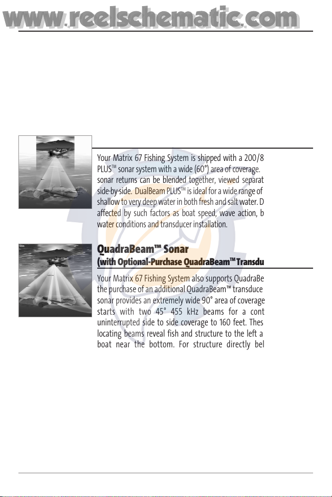
DualBeam PLUS™ Sonar
Your Matrix 67 Fishing System is shipped with a 200/83 kHz DualBeam
PLUS
TM
sonar system with a wide (60°) area of coverage. DualBeam PLUS
TM
sonar returns can be blended together, viewed separately or compared
side-by-side. DualBeam PLUS
TM
is ideal for a wide range of conditions - from
shallow to very deep water in both fresh and salt water. Depth capability is
affected by such factors as boat speed, wave action, bottom hardness,
water conditions and transducer installation.
QuadraBeam™ Sonar
(with Optional-Purchase QuadraBeam
TM
Transducer)
Your Matrix 67 Fishing System also supports QuadraBeam™ sonar with
the purchase of an additional QuadraBeam™ transducer. QuadraBeam™
sonar provides an extremely wide 90° area of coverage. QuadraBeam™
starts with two 45° 455 kHz beams for a continuous 90° of
uninterrupted side to side coverage to 160 feet. These Side Structure
locating beams reveal fish and structure to the left and right of your
boat near the bottom. For structure directly below your boat,
Quadrabeam™ uses DualBeam PLUS™ technology.
www.reelschematic.com
www.reelschematic.com
2
WideSide Sonar
(with Optional-Purchase WideSide Transducer)
Your Matrix 67 Fishing System also supports WideSide sonar with the purchase of an additional
WideSide transducer. The WideSide transducer is a specialized "side-looking" transducer that is
extremely useful for bank fishing or looking for bait fish in open water. The WideSide transducer uses
three different sonar elements that transmit signals to the left, right and straight down from your boat.
The downward beam is 200 kHz with a 24° area of coverage. This beam maintains a continuous digital
depth readout from the bottom directly beneath your boat. The side beams are 455 kHz with a 16° area
of coverage. The side-looking elements can be used independently, or together to locate targets near
the surface of the water on either side of your boat.
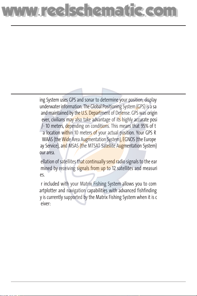
How GPS and Cartography Work
Your Matrix Fishing System uses GPS and sonar to determine your position, display it on a grid, and
provide detailed underwater information. The Global Positioning System (GPS) is a satellite navigation
system designed and maintained by the U.S. Department of Defense. GPS was originally intended for
military use; however, civilians may also take advantage of its highly accurate position capabilities,
typically within +/- 10 meters, depending on conditions. This means that 95% of the time, the GPS
receiver will read a location within 10 meters of your actual position. Your GPS Receiver also uses
information from WAAS (the Wide Area Augmentation System), EGNOS (the European Geostationary
Navigation Overlay Service), and MSAS (the MTSAT Satellite Augmentation System) satellites if they
are available in your area.
GPS uses a constellation of satellites that continually send radio signals to the earth. Your present
position is determined by receiving signals from up to 12 satellites and measuring the distance
from the satellites.
The GPS Receiver included with your Matrix Fishing System allows you to combine easy-to-use
FishingGPS™ chartplotter and navigation capabilities with advanced fishfinding. The following
GPS functionality is currently supported by the Matrix Fishing System when it is connected to the
included GPS receiver:
• View current position
• View current track (breadcrumb trail)
• View precision speed and heading from your GPS receiver
• Save tracks, waypoints and routes
• Travel a route and navigate from one waypoint to the next.
www.reelschematic.com
www.reelschematic.com
3
Your Matrix Fishing System supports Navionics® Gold Chart
marine cartography and Navionics® HotMaps
TM
2004 Gold for
inland fishing.
NOTE: Your Matrix Fishing System does not support Navionics®
Classic Charts, only Navionics® Gold Charts and Navionics®
HotMapsTM2004 Gold Charts.
Your unit also comes with a built-in World map with a more
detailed map of North America (Domestic models) or a more
detailed map of Europe and Southeast Asia, including
Australia and New Zealand (International models).
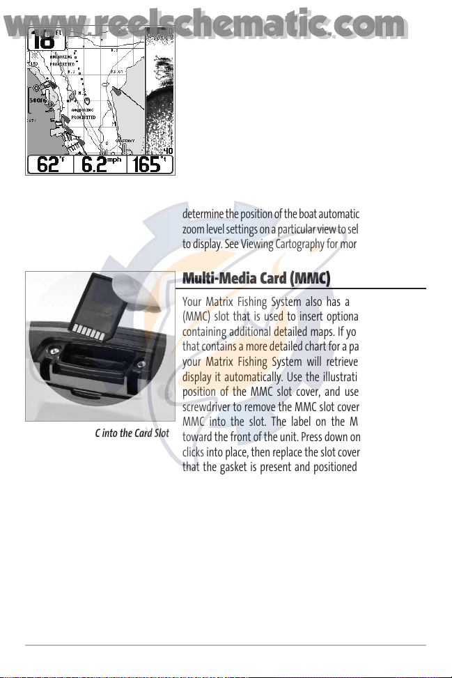
Your Matrix Fishing System uses the GPS Receiver to
determine the position of the boat automatically, and uses the
zoom level settings on a particular view to select the best chart
to display. See Viewing Cartography for more information.
Multi-Media Card (MMC)
Your Matrix Fishing System also has a multi-media card
(MMC) slot that is used to insert optional-purchase cards
containing additional detailed maps. If you insert an MMC
that contains a more detailed chart for a particular location,
your Matrix Fishing System will retrieve that chart and
display it automatically. Use the illustration to locate the
position of the MMC slot cover, and use a Phillips head
screwdriver to remove the MMC slot cover, then insert the
MMC into the slot. The label on the MMC should face
toward the front of the unit. Press down on the card until it
clicks into place, then replace the slot cover, making certain
that the gasket is present and positioned correctly before
re-installing the cover, then replace and tighten the screws
snugly - do NOT overtighten, as this will not improve water
resistance, and may damage the cover.
Inserting an MMC into the Card Slot
M67 Combo View Showing
Detailed Map
www.reelschematic.com
www.reelschematic.com
4
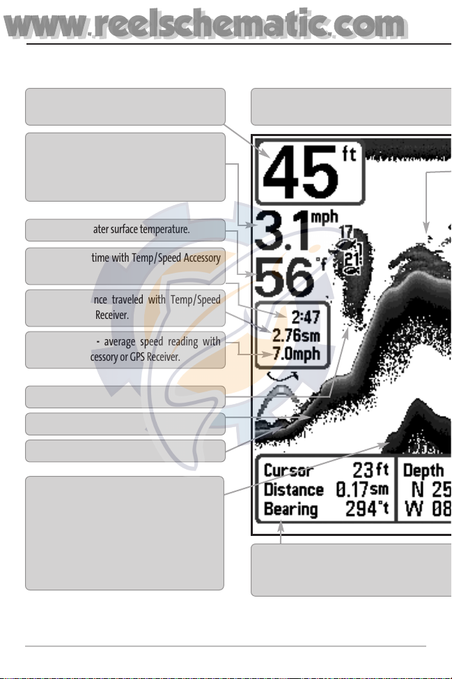
What’s On the Sonar Display
The Matrix Fishing System can display a variety of useful information about the area under and adjacent
Timer - elapsed time with Temp/Speed Accessory
or GPS Receiver.
Depth - water depth; can be set to alarm when the
water becomes too shallow.
Speed - if a Temp/Speed accessory or GPS Receiver
is attached, the Matrix Fishing System can display
the speed of the boat, and can keep a Triplog of
nautical or statute miles traveled.
Second Sonar Return - when the sonar signal
bounces between the bottom and the surface of
the water and back again. Use the appearance of
the second return to determine bottom hardness.
Hard bottoms will show a strong second return,
while soft bottoms will show a very weak one or
none at all.
Cursor Dialog Box - indicates cursor depth on the
the cursor position is shown, the distance to
cursor position for later retrieval and use.
Bait Ball
Hard Bottom
Rocky Bottom
Distance - distance traveled with Temp/Speed
Accessory or GPS Receiver.
NOTE: Entries in this view that list (with Temp/Speed or GPS Receiver) are available if either device is connected
receiver will be displayed on the view.
Temperature - water surface temperature.
Average Speed - average speed reading with
Temp/Speed Accessory or GPS Receiver.
Cursor - available in Freeze Frame and can be
sonar return and bottom depth below the cursor.
www.reelschematic.com
www.reelschematic.com
5
to your boat, including the following items:
display and the depth of the bottom directly below the cursor. In addition, the Latitude and Longitude of
travel to the cursor position and the bearing to the cursor position. A waypoint can be marked at the
RTS® (Real Time Sonar) Window
Soft Bottom
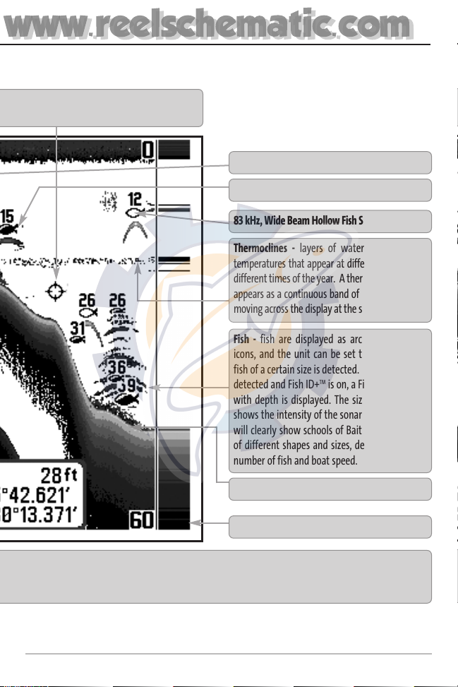
Thermoclines - layers of water with different
temperatures that appear at different depths and
different times of the year. A thermocline typically
appears as a continuous band of many gray levels
moving across the display at the same depth.
Fish - fish are displayed as arches and/or fish
icons, and the unit can be set to alarm when a
fish of a certain size is detected. When a target is
detected and Fish ID+
TM
is on, a Fish ID+TMsymbol
with depth is displayed. The size of the symbol
shows the intensity of the sonar return. The unit
will clearly show schools of Bait Fish as "clouds"
of different shapes and sizes, depending on the
number of fish and boat speed.
200 kHz, Narrow Beam Shaded Fish Symbol
to the Matrix Fishing System. If both devices are connected, then only the information from the GPS
positioned in the Sonar View to provide depth of a
83 kHz, Wide Beam Hollow Fish Symbol
Structure - where fish may be hiding.
www.reelschematic.com
www.reelschematic.com
6
Views
The views available on your Matrix Fishing System are:
Sonar views:
Navigation views:
• Sonar View • Bird’s Eye View
• Zoom View • Chart View
• 200/83 kHz Split Sonar View • Combo View
• Big Digits View
• Side Beam View
• WideSide View
NOTE: Side Beam View and WideSide View require the purchase of the QuadraBeamTMtransducer
for the Side Beam View and the WideSide transducer for the WideSide View. You can visit our
website at www.humminbird.com to order these accessories online or contact our Customer
Resource Center at 1-334-687-0503.
Sonar View is the default view. When the VIEW key is pressed, the display cycles through the available
views. When the EXIT key is pressed, the display cycles through the available views in reverse order.
Any view can be hidden or displayed as part of the view rotation using Select View from the Advanced
Setup Menu.
NOTE: When you change any menu settings that affect the sonar, the view will update immediately (i.e.
you don’t have to exit the menu to apply the change to the screen). For instance, by switching between
"Inverse" and "Structure ID®" from the X-PressTMmenu it is possible to quickly alternate between the two
viewing methods.
www.reelschematic.com
www.reelschematic.com
7
Sonar View
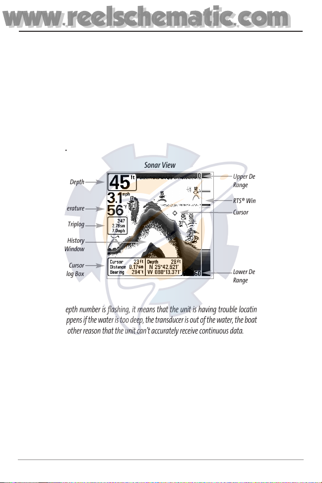
Sonar View presents a historical log of sonar returns. Depth is always displayed. Readouts for
temperature and speed are automatically displayed if the appropriate accessory is connected. The
most recent sonar returns are charted on the right side of the window; as new information is
received, the older information is moved across the display to the left. A Digital Depth Readout is
displayed in the upper left corner. A scale with Upper and Lower Depth Range readouts appears along
the right edge of the Sonar View. The scale indicates the distance from the surface of the water to a
depth range sufficient to show the bottom. Depth Range is automatically selected to keep the
bottom visible on the display, although you can adjust it manually as well (see Sonar X-Press
TM
Menu).
Six additional Digital Readouts display information from optional-purchase accessories. These
information boxes can be customized to show only the information desired (see Setup Menu Tab,
Select Readouts).
NOTE: If the Depth number is flashing, it means that the unit is having trouble locating the bottom.
This usually happens if the water is too deep, the transducer is out of the water, the boat is moving too
fast, or for any other reason that the unit can’t accurately receive continuous data.
Freeze Frame - Pressing any arrow on the 4-WAY Cursor Control key will freeze the screen in the Sonar
View and a cursor and cursor dialog box will be displayed on the screen. The cursor can be positioned
on the display using the 4-WAY Cursor Control key to determine the depth of any sonar return. The
RTS® Window continues to update in Freeze Frame. In addition, see the effects of menu setting
changes with Instant Image Update. Pressing EXIT will exit Freeze Frame and the display will start to
scroll. Freeze Frame is only available in the Sonar View.
Sonar View
Upper Depth
Range
Sonar History
Window
Depth
Cursor
Dialog Box
Temperature
Triplog
Lower Depth
Range
RTS® Window
Cursor
www.reelschematic.com
www.reelschematic.com
8
Understanding Sonar History
It is important to understand the significance of the Matrix Fishing System display. The display does
NOT show a literal 3-dimensional representation of what is under the water. Each vertical band of data
received by the control head and plotted on the display represents something that was detected by a
sonar return at a particular time. As both the boat and the targets (fish) may be moving, the returns
are only showing a particular segment of time when objects were detected, not exactly where those
objects are in relation to other objects shown on the display.
Real Time Sonar (RTS®) Window
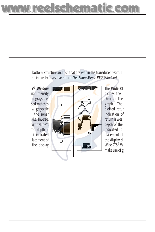
A Real Time Sonar (RTS®) Window appears on the right side of the display in the Sonar View only. The
RTS® Window always updates at the fastest rate possible for depth conditions and shows only the
returns from the bottom, structure and fish that are within the transducer beam. The RTS® Window
plots the depth and intensity of a sonar return. (See Sonar Menu: RTS® Window) .
The Narrow RTS® Window
indicates the sonar intensity
through the use of grayscale.
The grayscale used matches
the bottom view grayscale
setting used in the sonar
history window (i.e. Inverse,
StructureID®, WhiteLine®,
Bottom Black). The depth of
the sonar return is indicated
by the vertical placement of
the return on the display
depth scale.
The Wide RTS® Window indicates the sonar intensity
through the use of a bar
graph. The length of the
plotted return provides an
indication of whether the
return is weak or strong. The
depth of the sonar return is
indicated by the vertical
placement of the return on
the display depth scale. The
Wide RTS® Window does not
make use of grayscale.
www.reelschematic.com
www.reelschematic.com
9
Bottom Presentation
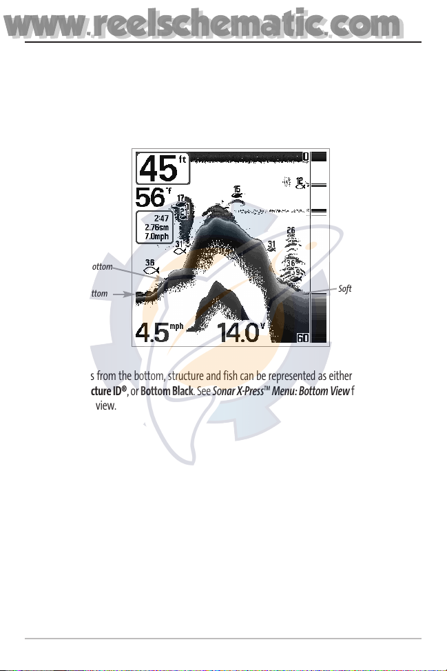
As the boat moves, the unit charts the changes in depth on the display to create a profile of the Bottom
Contour. The type of bottom can be determined from the return charted on the display. A Hard Bottom
such as compacted sediment or flat rock appears as a thinner line across the display. A Soft Bottom such
as mud or sand appears as a thicker line across the display. Rocky Bottoms have a broken, random
appearance.
The sonar returns from the bottom, structure and fish can be represented as either Inverse (default),
WhiteLine®, Structure ID®, or Bottom Black. See Sonar X-Press
TM
Menu: Bottom View for details on how
to set the bottom view.
Bottom Contour Profile with RTS® Window.
Rocky Bottom
Hard Bottom
Soft Bottom
www.reelschematic.com
www.reelschematic.com
10
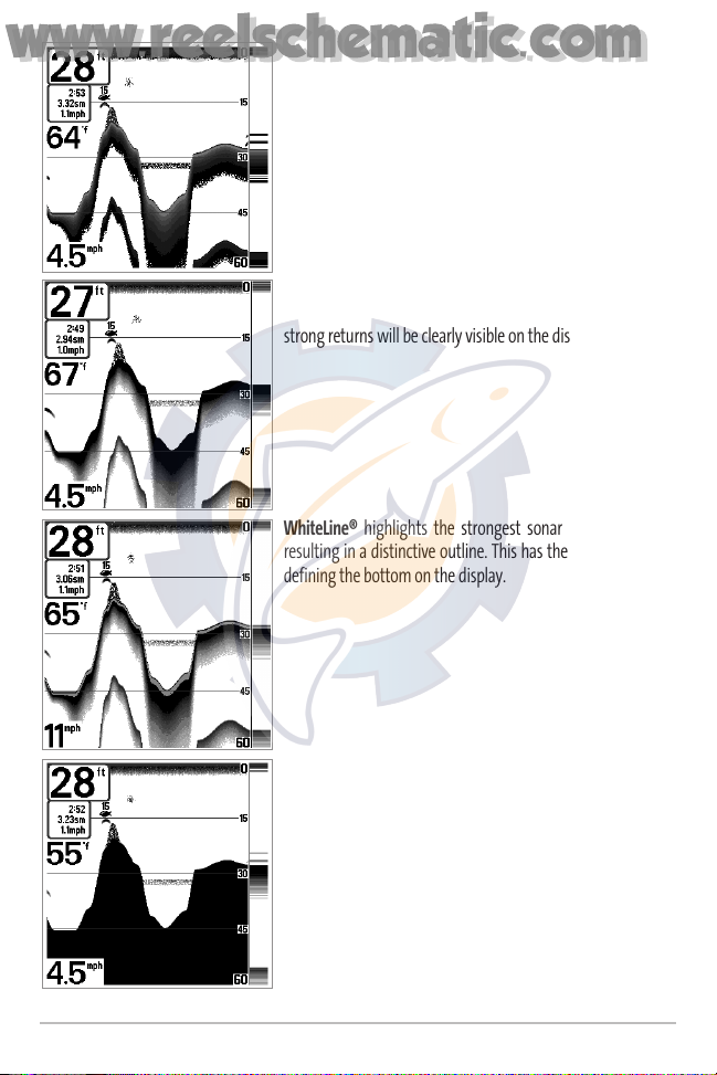
Inverse is a method where weak returns are shown with dark
pixels and strong returns with lighter pixels. This has the benefit
of ensuring that weak signals will be clearly visible on the
display.
Structure ID® represents weak returns as light pixels and strong
returns as dark pixels. This has the benefit of ensuring that
strong returns will be clearly visible on the display.
WhiteLine® highlights the strongest sonar returns in white,
resulting in a distinctive outline. This has the benefit of clearly
defining the bottom on the display.
Bottom Black displays all pixels below the bottom contour as
black, regardless of signal strength. This has the benefit of
providing a high contrast between the bottom and other sonar
returns on the display. Any targets such as fish, structure and
thermoclines will be shown using the Structure ID® method.
www.reelschematic.com
www.reelschematic.com

11
Sonar Zoom View
Sonar Zoom View increases the displayed resolution to separate sonar returns that are very close
together, such as those caused by fish suspended close to the bottom or within structure. In Zoom
View, the display is split to show a narrow slice of the full range view on the right and the zoomed view
on the left. The full range view on the right also contains the Zoom Preview Box that shows what part
of the full range view is shown in zoom view on the left; the Zoom Preview Box tracks the bottom in
the full range view.
As the depth changes, the zoomed view updates automatically to display a magnified image of the
bottom. The Zoom Preview Box shows where the zoomed view is in relation to the full range view. The
Zoom Level, or magnification, is displayed in the lower left corner and can be changed to suit conditions
(see Sonar X-Press
TM
Menu: Zoom Level). Upper and Lower Zoom Depth Range numbers indicate the
depth of the water which is being viewed.
Digital depth is displayed in the upper left hand corner. The digital readouts in the Sonar Zoom View
cannot be customized; therefore, information such as water temperature and voltage are unavailable
in the Sonar Zoom View.
Sonar Zoom View
Upper Depth
Range, Zoom View
Upper Depth
Range, Full
Range View
Full Range
View
Zoom
Preview Box
Lower Depth
Range, Full
Range View
Zoomed
View
Zoom Level
Depth
Lower Depth Range,
Zoom View
www.reelschematic.com
www.reelschematic.com
12
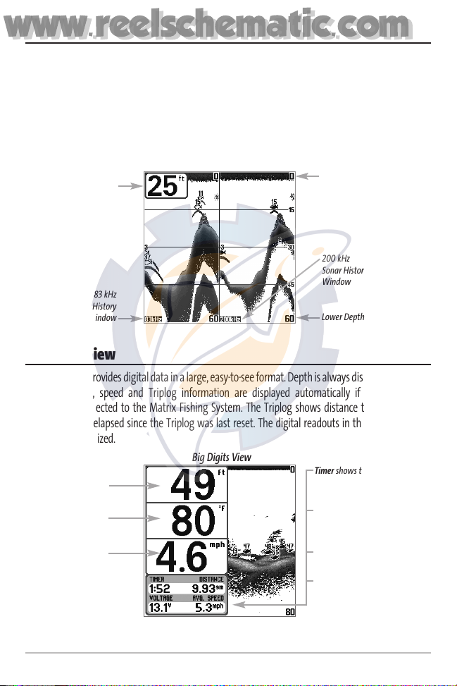
200/83 kHz Split Sonar View
Split Sonar View displays sonar returns from the 83 kHz wide beam on the left side of the screen and
displays sonar returns from the 200 kHz narrow beam on the right side of the screen. Depth is always
displayed in the upper left hand corner. You can use the Split Sonar View to make side by side
comparisons between the sonar returns from the 83 kHz wide beam and the 200 kHz narrow beam.
The digital readouts in the Split Sonar View cannot be customized; therefore, information such as
water temperature and voltage are unavailable in the Split Sonar View.
Big Digits View
Big Digits View provides digital data in a large, easy-to-see format. Depth is always displayed. Readouts
for temperature, speed and Triplog information are displayed automatically if the appropriate
accessory is connected to the Matrix Fishing System. The Triplog shows distance traveled, average
speed, and time elapsed since the Triplog was last reset. The digital readouts in the Big Digits View
cannot be customized.
Big Digits View
Depth
Temperature
Speed
Timer shows the time
elapsed since Triplog
was last reset
Distance is the distance
traveled since the Triplog
was last reset
Voltage - the battery
voltage.
Average Speed shows
the speed since the
Triplog was last reset
200/83 kHz Split Sonar View
Depth
83 kHz
Sonar History
Window
200 kHz
Sonar History
Window
Lower Depth Range
Upper Depth
Range
www.reelschematic.com
www.reelschematic.com
13
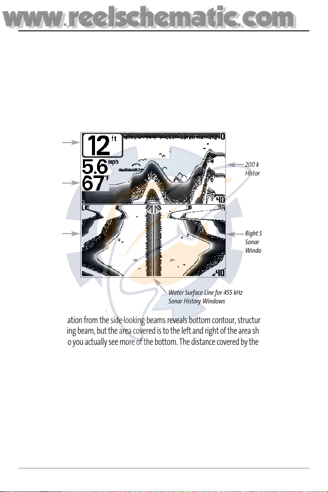
Side Beam View
Side Beam View is only available if you have connected a QuadraBeamTMtransducer accessory and
when Transducer Select is set to QuadraBeam™ (see Sonar Menu Tab: Transducer Select). The
QuadraBeam™ transducer requires a separate purchase. This view shows sonar information from
both the left and right 90° 455 kHz beams and the 200 kHz down-looking beam in one view. The
top portion of the display presents a historical log of sonar returns from the 200 kHz down-looking
sonar. The bottom portion of the display presents a historical log of sonar returns from the 455 kHz
right- and left-looking sonar. New information appears at the top, and scrolls down the display.
The sonar information from the side-looking beams reveals bottom contour, structure and fish similar
to the down-looking beam, but the area covered is to the left and right of the area shown in the downlooking portion, so you actually see more of the bottom. The distance covered by the right and left 90°
beams is based on the depth setting for the down-looking beam, up to a maximum of 160 feet.
Side Beam View
Depth
Temperature
Left Side 455 kHz
Sonar History
Window
Right Side 455 kHz
Sonar History
Window
200 kHz Sonar
History Window
Water Surface Line for 455 kHz
Sonar History Windows
www.reelschematic.com
www.reelschematic.com
14
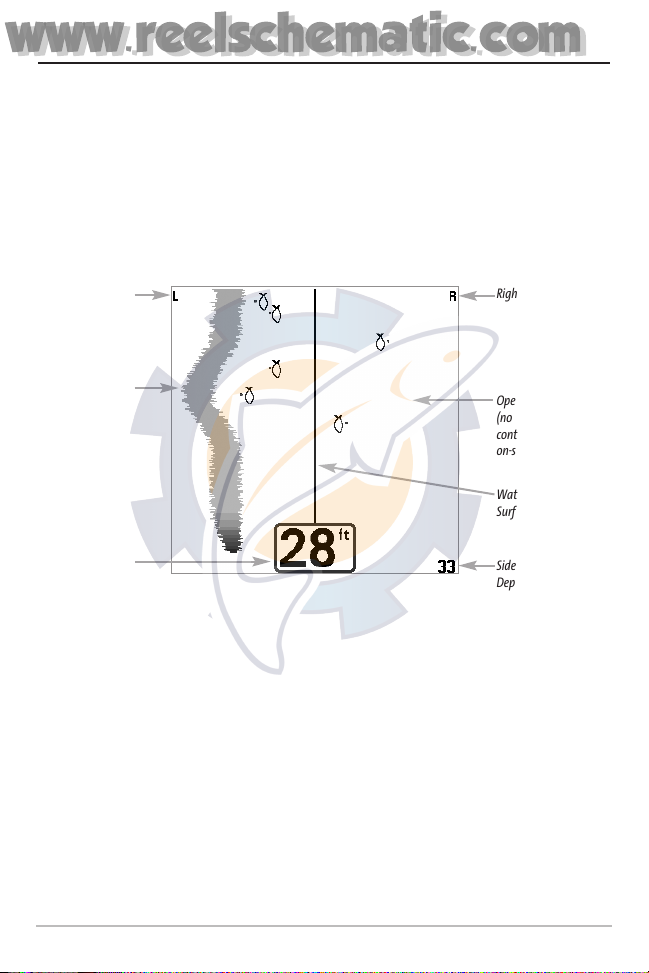
WideSide View
WideSide View is only available if you have connected a WideSide transducer accessory and when
Transducer Select is set to WideSide (see Sonar Menu Tab: Transducer Select). The WideSide
transducer requires a separate purchase. The WideSide View displays information from the 455 kHz
SideView transducer. Three views are available: Left, Right and Both. The default view is Both.
Information from both the left and right beams are displayed simultaneously. The depth of the water
beneath the boat is always displayed. A bottom contour may be present while bank fishing or fishing
river channels. When fishing in the open water, a bottom contour will not be present, and only sonar
returns from either debris or fish will be displayed.
WideSide View
Left Side View
Bank Contour
Water
Surface Line
Depth
Right Side View
Open Water
(no bottom
contour visible
on-screen)
Side Beam
Depth Range
www.reelschematic.com
www.reelschematic.com
15
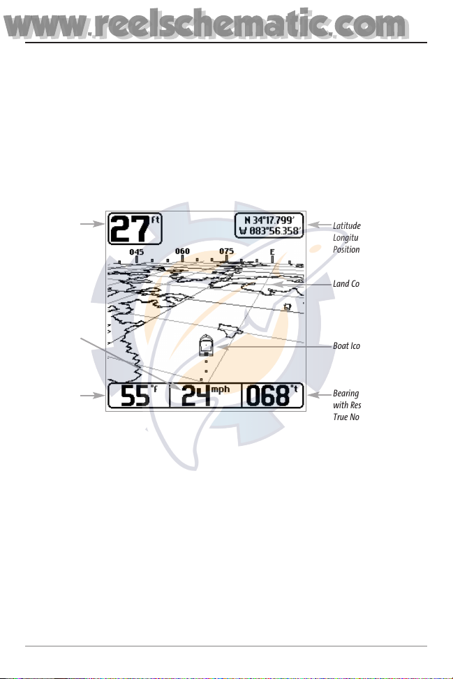
Bird’s Eye View
Bird's Eye View - This view shows a 3-D, perspective view of the track and the chart’s land contour from a
point above and behind the boat (the eye point). As the boat turns, the eye point moves to follow the boat.
When you press the 4-WAY Cursor key in the Bird’s Eye View, the position of the eye point will shift. This
allows you to move and turn the eye point so that you can look off to the sides, or even behind the boat.
Pressing the RIGHT or LEFT arrow keys on the 4-WAY Cursor key turns the eye point right or left, while
pressing the UP arrow key moves the eye point forward, and pressing the DOWN arrow key moves the
eye point backward.
Pressing the EXIT key moves the eye point back to its original position behind and above the boat.
Bird’s Eye View
Depth
Land Contours
Boat Icon
Water Surface
Temperature
Latitude and
Longitude
Position of Boat
Speed of Boat
Bearing of Boat
with Respect to
True North
www.reelschematic.com
www.reelschematic.com
16
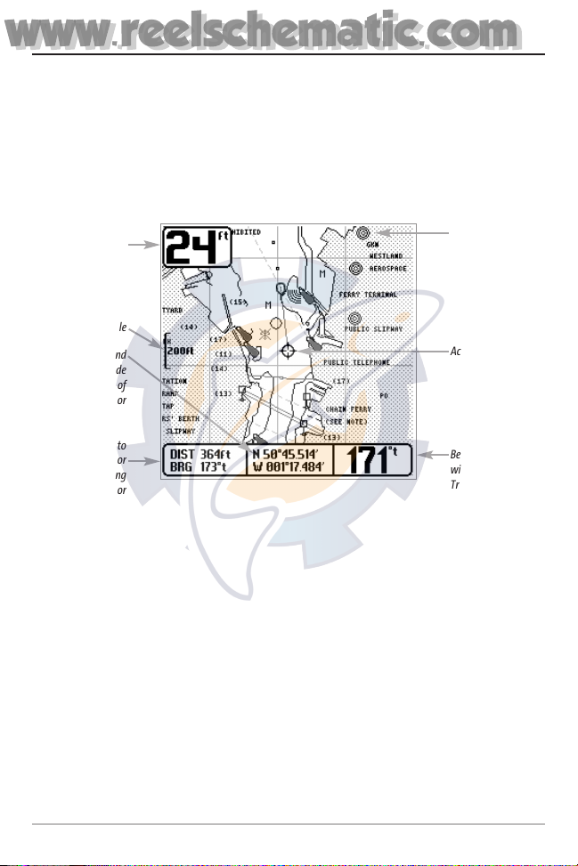
Chart View
Chart View - This view shows cartography from the built-in UniMap or an optional MMC map for the
area surrounding your current position. The current track (also known as the position history or
breadcrumb trail) showing where the boat has been, along with saved tracks, waypoints, and the
current route (when navigating), are overlaid on the chart. You can use the 4-WAY Cursor Control key
to shift/pan the chart to another area. You can use the ZOOM (+/-) keys to zoom in and out. You can
use the INFO key to get information on the chart objects near the cursor.
Chart View with Active Cursor
Depth
Cartography
Latitude and
Longitude
Position of
Cursor
Bearing of Boat
with Respect to
True North
Distance to
the Cursor
and Bearing
to Cursor
Map Scale
Active Cursor
www.reelschematic.com
www.reelschematic.com
17
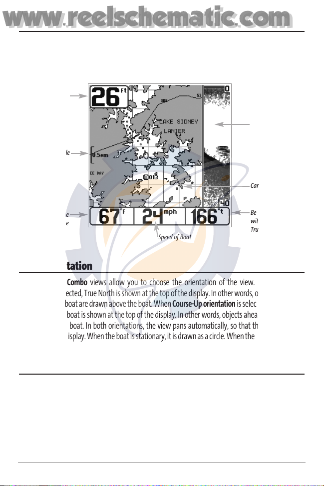
Combo View
Combo View - This view is displayed as a split screen, with Chart View on the left and Sonar View on
the right side of the screen. The width of the sonar window can be changed.
View Orientation
Both Chart and Combo views allow you to choose the orientation of the view. When North-Up
orientation is selected, True North is shown at the top of the display. In other words, objects located to
the north of the boat are drawn above the boat. When Course-Up orientation is selected, the direction
of motion of the boat is shown at the top of the display. In other words, objects ahead of the boat are
drawn above the boat. In both orientations, the view pans automatically, so that the boat is always
centered on the display. When the boat is stationary, it is drawn as a circle. When the boat is in motion,
it takes on a boat shape, pointed in the direction of motion (always Up in the Course-Up orientation).
Viewing Cartography
In the Chart or Combo Views, there are several cartography-related functions that you can access
using various keys.
Combo View
Depth
Depth
Cartography
Sonar Window
Bearing of Boat
with Respect to
True North
Water Surface
Temperature
Speed of Boat
Map Scale
www.reelschematic.com
www.reelschematic.com
18
Panning: Use the 4-WAY Cursor keys to move the chart around
on the display in the direction of the key being pressed. When
you do this, a bullseye cursor is drawn at the center of the
screen and is linked to the boat by a gray line, even if the boat
is off the screen. At the same time, the temperature and speed
boxes in the lower left corner are replaced with the distance
and bearing from the boat to the cursor position and the
latitude/longitude coordinates of the cursor.
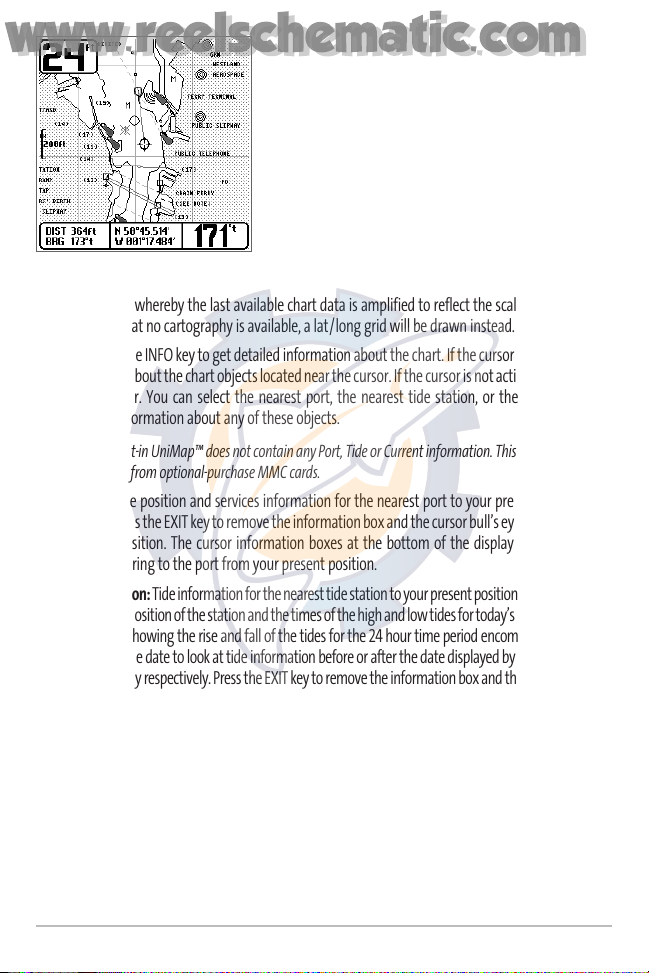
Zooming: Use the Plus (+) key to Zoom In and the Minus (-) key
to Zoom Out showing the cartography at different scales. The
scale is indicated on the left side of the display. If you zoom in
beyond the available chart data, the display will go into
Overzoom mode whereby the last available chart data is amplified to reflect the scale selected. If you
zoom in so far that no cartography is available, a lat/long grid will be drawn instead.
Chart Info: Use the INFO key to get detailed information about the chart. If the cursor is active, you will
see information about the chart objects located near the cursor. If the cursor is not active, the Chart Info
menu will appear. You can select the nearest port, the nearest tide station, or the nearest current
station to see information about any of these objects.
NOTE: The built-in UniMap™ does not contain any Port, Tide or Current information. This information is
only available from optional-purchase MMC cards.
Nearest Port: The position and services information for the nearest port to your present position will
be displayed. Press the EXIT key to remove the information box and the cursor bull’s eye will be centered
over the port position. The cursor information boxes at the bottom of the display will indicate the
distance and bearing to the port from your present position.
Nearest Tide Station: Tide information for the nearest tide station to your present position will be displayed.
This includes the position of the station and the times of the high and low tides for today’s date. A tide graph
is also displayed showing the rise and fall of the tides for the 24 hour time period encompassing the date.
You can change the date to look at tide information before or after the date displayed by pressing the LEFT
or RIGHT cursor key respectively. Press the EXIT key to remove the information box and the cursor bull’s eye
will be centered over the tide station position. The cursor information boxes at the bottom of the display
will indicate the distance and bearing to the tide station from your present position.
Nearest Current Station: Current information for the nearest current station to your present position
will be displayed. This includes the position of the station and the current changes for today. Two
graphs are also presented that show the time, direction and flow speed of the current changes for the
24 hour time period of today’s date. You can change the date to look at current information before or
after the date displayed by pressing the LEFT or RIGHT cursor key respectively. Press the EXIT key to
remove the information box and the cursor bull’s eye will be centered over the current station position.
The cursor information boxes at the bottom of the display will indicate the distance and bearing to the
current station from your present position.
Chart View with Cursor Present
www.reelschematic.com
www.reelschematic.com
19
Introduction to Navigation
Use the Matrix Fishing System to establish waypoints at areas of interest and to navigate to those
waypoints via a saveable route (representing the shortest intended distance between waypoints). You
can also view and save tracks, which represent the actual path of the boat.
Waypoints, Routes and Tracks
Waypoints are stored positions that allow you to mark areas of interest or navigation points. Your
Matrix Fishing System can store up to 750 waypoints.
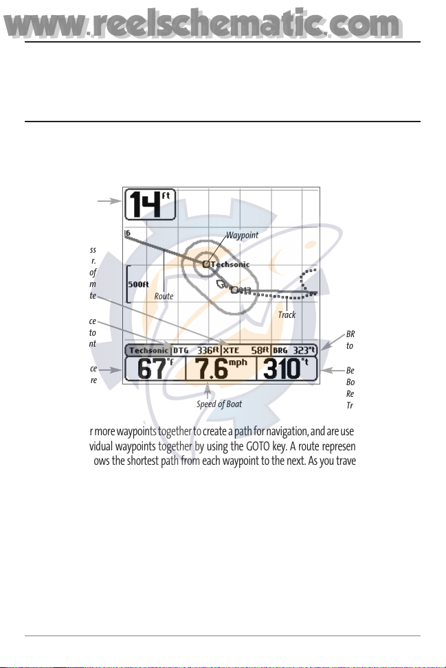
Routes link two or more waypoints together to create a path for navigation, and are used in trip planning.
You can link individual waypoints together by using the GOTO key. A route represents your intended
navigation and shows the shortest path from each waypoint to the next. As you travel a route, staying
on the route line is the most efficient way to get to your destination, although you should always look
out for obstacles not shown on the chart. Your Matrix Fishing System can store up to 10 routes that can
each contain up to 20 waypoints.
Tracks consist of detailed position history, and are displayed as a breadcrumb trail of trackpoints. The
Current Track shows the position history since the unit was powered up (maximum of 2000 trackpoints
displayed). You can clear the Current Track or save it at any time. Your Matrix Fishing System can store up
to 10 saved tracks, each containing 2000 trackpoints. The current track represents your actual path so far.
Waypoints, Routes and Tracks
Route
Track
Waypoint
Depth
Water Surface
Temperature
DTG: Distance
to Go to
Waypoint
Speed of Boat
XTE: Cross
Track Error.
Distance of
Boat from
Route
Bearing of
Boat with
Respect to
True North
BRG: Bearing
to Waypoint
www.reelschematic.com
www.reelschematic.com

20
Save, Edit, or Delete a Waypoint
Save your current position as a waypoint: On any view, press the MARK key to save the current
position of the boat as a waypoint.
Save the cursor position as a waypoint: On the Chart or Combo view, use the Cursor key to
designate the position you want to save as a waypoint. Then press the MARK key to save the
marked position as a waypoint.
Save a position from the sonar history: On the Sonar view, use the Cursor key to point to a feature
in the sonar history (also called the Sonar Saver feature). Press the MARK key to create a waypoint
at the location where that sonar reading was taken. The new waypoint will also record the depth
at that location.
NOTE: When you save a waypoint by any of these methods, a numerical waypoint name is
automatically assigned. You can edit the waypoint information later to give it a different name and
select an icon to represent it (see Waypoint submenu on the Navigation Main Menu Tab).
Display the Waypoints Submenu: From any view, press the MENU key twice to display the Main
Menu System, then use the RIGHT Cursor key to select the Navigation tab. Select Waypoints and
press the RIGHT Cursor key to display the Waypoints submenu.
Program a specific position as a waypoint: To create a waypoint that is NOT your current position,
from the Waypoints submenu, select the Create option and press the RIGHT Cursor key. Use the
Cursor keys to program a waypoint name, latitude, longitude, and icon before selecting Save.
Edit a waypoint: From the Waypoints submenu, select Edit and press the RIGHT Cursor key to
display a list of saved waypoints. Select the waypoint you want to edit and press the RIGHT Cursor
key. Use the 4-WAY Cursor Control key to move from field to field, and the UP and DOWN Cursor
keys to changes values once you are in a field. In the Waypoint Name, Latitude and Longitude fields,
use the UP and DOWN Cursor keys to change the letter or number. All upper and lower case letters
are available, as well as digits 0-9 and some punctuation characters. In the Waypoint Icon field, use
the UP and DOWN Cursor keys to change the icon used to represent the waypoint on the Combo
and Chart Views. You can exit these fields with the LEFT and RIGHT Cursor keys or by pressing the
EXIT key. Select Save and press the RIGHT Cursor key to save your changes.
To make it easier to select a waypoint, select Sort By and press the RIGHT or LEFT Cursor keys to
select a sort order:
• Name shows the waypoints alphabetically
• Time shows the most recently-created waypoint first
• Distance shows the closest waypoint first.
www.reelschematic.com
www.reelschematic.com

Delete a waypoint: From the Waypoints submenu, select Delete and press the RIGHT Cursor key to
display a list of waypoints. Select the waypoint you want to delete, then press the RIGHT Cursor
key. You will be asked to confirm deletion before the waypoint is actually deleted.
Navigate to a Waypoint or Position
Navigate to the cursor position: From the Chart or Combo view, use the Cursor key to select a
position or waypoint to which you want to navigate. Press the GOTO key. Navigation will begin
immediately.
Navigate to a specified waypoint: Press the GOTO key, then choose the waypoint to which you
would like to navigate from the waypoint list and press the RIGHT Cursor key to select it.
NOTE: By repeating the previous instructions, you can add more waypoints to create a longer multi-
segment route.
Skipping a waypoint: From the Navigation X-PressTMmenu, select Skip Next Waypoint and press
the RIGHT Cursor key. If there is not another waypoint to skip to, navigation will be cancelled.
Cancel navigation: From the Navigation X-PressTMmenu, select Cancel Navigation and press the
RIGHT Cursor key. Canceling navigation removes the route and any waypoints created using the
GOTO key, but does not remove any saved routes from memory. You will be prompted to save the
current route when you cancel navigation.
21
www.reelschematic.com
www.reelschematic.com
 Loading...