

Humminbird 531392-2_B Quick Manual
1
Plastic Thru-Hull Side Imaging Transducer
Thank You
Thank you for choosing Humminbird®, the #1 name in fishfinders. Humminbird® has built its reputation by designing
and manufacturing top-quality, thoroughly reliable marine equipment. Genuine Humminbird® accessories offer the
opportunity to upgrade and expand the capabilities of your Humminbird® product.
Your Humminbird® is designed for trouble-free use in even the harshest marine environment. In the unlikely event that
your Humminbird® does require repairs, we offer an exclusive Service Policy - free of charge during the first year after
purchase, and available at a reasonable rate after the one-year period. For complete details, see the Warranty section
included in this manual.
Contact our Customer Resource Center at 1-800-633-1468 or visit our Web site at humminbird.com.
Installation Overview
Following are instructions for the installation of this accessory. Before you start installation, we encourage you to read
these instructions carefully in order to get the full benefit from your Humminbird® accessory.
If you find that any items are missing from your installation kit, call our Customer Resource Center at 1-800-633-1468
or visit our Web site at humminbird.com.
NOTE: This type of transducer installation is not recommended for trailerable boats.
NOTE: This transducer requires drilling a hole in the hull of the boat; therefore, installation should be performed by a
qualified marine technician.
In addition to the hardware supplied with your transducer, you will need a drill, a small drill bit for a pilot hole, a
1 1/8" hole saw, a level, and marine-grade silicone sealant.
531392-2_B
Thru-Hull Installation
Deadrise Angle
Installation
Perform the procedures in the following sections to install the transducer on your boat.
1. Testing the Transducer Prior to Installation
Prior to installation, test the transducer to make sure that no damage occurred during shipping.
1. After connecting the transducer to the control head, hold the transducer in the water over the side of the boat
to confirm proper operation. If the transducer is working properly, you should be able to see the bottom on the
control head display. The bottom image should be relatively strong and there should be detailed structure on the
display.
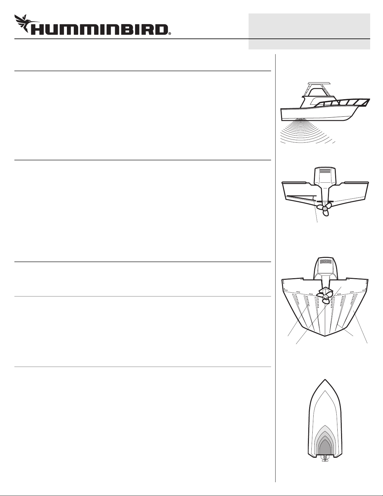
2. Locating the Transducer Mounting Position
Outside the boat: The best location for the transducer will be aft midship, as close to the centerline of the boat as
possible. The transducer should be mounted forward of the propellers on inboard boats, and separated adequately
from other transducers, strakes, rivet lines, or other protrusions. Make sure that there is nothing in front, behind, or to
the side of the transducer that is closer than 12".
WARNING! Do NOT install the transducer in line with the engine intake.
Inside the boat: There must be room to access the mounting location for installation and cable routing.
Deadrise: Another consideration is the angle of deadrise.
Areas of Possible Turbulence
Rivets Strakes
Transom Hull
Preferred Mounting Location
• The transducer, when mounted, should pointstraight down. If the selectedmounting location has a hull deadrise
of 2 degrees or greater, the included leveling block should be used to level the transducer housing and direct the
sonar signal straight down.
• If you need to use the leveling block, make sure that the inside surface of the hull is smooth enough to seat the
leveling block securely.
2
Plastic Thru-Hull Side Imaging Transducer
Side Imaging: The side imaging transducer has some special requirements because of its side viewing capabilities.
• The side imaging transducer must not have anything obstructing the ”view” of the side looking beams, i.e.
nothing can be in the line of sight of these beams (not a hull, motor, or other transducer, etc).
In order for the side beams to be displayed accurately, the transducer must be mounted so that it is looking
•
straight down in the water when the boat is in the water.
NOTE: Rough seas can also affect the reading of the side imaging transducer.
Installation scenarios for consideration:
• Flat Hull, One Transducer: Locate a flat area on the bottom of the hull, forward of where the propeller shaft
comes out of the hull. Make sure there is nothing lower than this location to the right or left.
• V-shaped Hull, Two Transducers: Install two thru-hull side imaging transducers, one on each side of the V.
Connect the transducers with AS SI LR Y cable.
• Two Back Engines, Two Transducers: Install two thru-hull side imaging transducers outboard from the dual
engines. Connect the transducers with AS SI LR Y cable.
NOTE: AS SI LR Y and additional Side Imaging Thru-Hull Transducers must be purchased separately. Also, if the included
transducer will not work for your application, you may exchange it, NEW and UNASSEMBLED, with mounting hardware
included, for a transducer appropriate for your application - often at very little or no charge depending on the transducer.
See the FAQ (Frequently Asked Questions) section of our Web site at humminbird.com or call our Customer Resource
Center at 1-800-633-1468.
531392-2_B
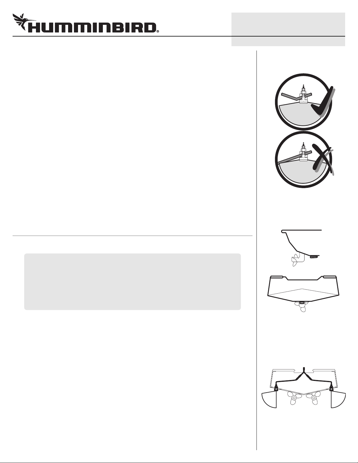
Side Imaging
Shows transducer close enough to center line so
that the hull will not interfere with side imaging
Shows transducer not close to center line, so that
the hull may interfere with side imaging
3. Drilling the Hole and Installing the Leveling Block
Follow the instructions below for the installation type that matches your hull and deadrise.
CAUTION: Use only the leveling block included with this transducer. Do NOT use a wooden leveling block, as any
swelling of the wood might cause the plastic on the transducer to shatter.
NOTE: A separately-purchased leveling block can also be used to create a hydrodynamic waterflow around the
transducer body. The design and fabrication of this block varies greatly with different hull shapes; therefore, it should
be customized by a qualified marine technician.
NOTE: Replacement leveling blocks are available from Humminbird®. For assistance, contact the Humminbird®
Customer Resource Center at humminbird.com or call 1-800-633-1468.
Standard Installation (Flat Hull, Deadrise less than 2°): For an installation that needs to minimize the impact of a
small obstruction, but where the deadrise is less than 1 - 2 degrees, use the included leveling block (uncut), and
mount it outside the hull.
1. From the outside of the hull, drill a small pilot hole (smaller than the centering bit of your drill bit or hole saw), at
the mounting location you selected in section 2. Drill the hole perpendicular to the hull.
2. Use the pilot hole (from the outside of the hull) to drill a 1 1/8" hole that is sized to fit the threaded stem of
the transducer. Drill the hole perpendicular to the hull.
3. Thoroughly clean and deburr the drilled hole and clean the outside of the hull.
Flat Hull, One Transducer
V-shaped Hull, Two Transducers
OR
Two Back In-Board Engines,
Two Transducers
4. The leveling block will be installed (uncut) on the outside of the hull. Proceed to Section 4: Attaching the
Transducer.
 Loading...