

Humminbird 531392-1 B, 531392-1 Installation Manual
Plastic Thru-Hull Side Imaging Transducer
5
531392-1_B
©2008 Humminbird®,EufaulaAL, USA.
Allrights reserved.
Returning Your Unit forService
Beforesending yourunit infor repair,please contactthe factory,either byphone or
byemail, toobtaina RepairAuthorizationNumber foryourunit.
NOTE: Pleasedo not returnyour Humminbird®to the storefor service.
Pleasehave yourproduct modelname andserial numberavailable beforecalling
thefactory. Ifyou contactthe factoryby e-mail,please includeyourproduct model
name andserial numberin thee-mail, anduse Request forRepair Authorization
Number for yo ur e-mail subject hea der. You should incl ude your Repair
AuthorizationNumberin allsubsequentcommunicationsabout yourunit.
ForIN-WARRANTY service, complete thefollowingsteps:
• Obtain aRepair AuthorizationNumber fromthe Humminbird®Customer
ResourceCenter.
• Tag product withyour name, street address,phone number and your
assignedRepair AuthorizationNumber.
• Include abrief writtendescription oftheproblem.
• Include acopy ofyourreceipt (toshow proofand dateof purchase).
• Return productfreightprepaid toHumminbird®,using aninsuredcarrier
withdelivery confirmation.
ForOUT-OF-WARRANTYservice, completethe followingsteps:
• Obtain aRepair AuthorizationNumber fromthe Humminbird®Customer
ResourceCenter.
• Include paymentin theform ofcredit cardnumberand expirationdate,
moneyorder orpersonalcheck. Pleasedonot sendcash.
• Tag product withyour name, street address,phone number and your
assignedRepair AuthorizationNumber.
• Include abrief writtendescription oftheproblem.
• Return productfreightprepaid toHumminbird®,using aninsuredcarrier
withdelivery confirmation.
Contact Humminbird®
Contactthe Humminbird®Customer ResourceCenter
i
nany ofthe followingways:
ByTelephone
(Monday- Friday8:00a.m. to4:30 p.m.CentralStandard Time):
1-800-633-1468
Bye-mail
(typicallywe respondto youre-mail withinthree businessdays):
cservice@johnsonoutdoors.com
Fordirect shipping,our addressis:
Humminbird
ServiceDepartment
678Humminbird Lane
Eufaula,AL 36027USA
WARNING!Do not touchan activetransducerduring operation,as thismay
cause physicaldiscomfort and may resultin personal injury in theform of
tissuedamage. Handlethetransducer onlywhenthe powerto thefishfinderis
off.
WARNING!This deviceshould not beused as anavigational aidto prevent
collision, grounding, boat damage, or personal injury. When the boat is
moving,water depth maychange too quickly toallow time foryou to react.
Alwaysoperate theboat atvery slow speeds ifyou suspectshallow wateror
submergedobjects.
WARNING! Disassembly and repairof this electronic unit shouldonly be
performed byauthorized service personnel. Any modificationof the serial
number or attempt to repa irt heo riginal equipment or access ories by
unauthorizedindividualswill voidthe warranty. Handlingand/or openingthis
unitmay resultinexposure tolead, intheform ofsolder.
WARNING! This productcontains lead, a chemicalknown to the stateof
Californiato causecancer,birth defectsand otherreproductiveharm.
The WEEE Directive aims to minimiz ethe impa ctof end- of-life
electric ala nde lectronic equipme nto nhu man health and the
environment.Therefore, anyproduct bearing theWEEE symbolmust
not beincluded withunsorted municipalwaste. Instead, itmust be
separatelycollected,treated andrecycled.
For properdisposal ofthis equipment, please contactthe JohnsonOutdoors
distributoror seewww.humminbird.com.
Thank You
Thank youfor choosing Humminbird®,America's #1 name infishfinders. Humminbird® hasbuilt its reputation by
d
esigning and manufacturing top-quality, thoroughlyreliable marine equipment. Genuine Humminbird® accessories
offerthe opportunityto upgradeand expandthe capabilitiesofyour Humminbird® product.
YourHumminbird® isdesignedfor trouble-freeuse ineven theharshestmarine environment.In theunlikely eventthat
yourHumminbird® doesrequirerepairs, weoffer anexclusive ServicePolicy -free ofcharge duringthe first year after
purchase,and available ata reasonablerate afterthe one-year period.For completedetails, see the Warrantysection
includedin thismanual.
Contactour CustomerResource Centerat either1-800-633-1468or visitour websiteat www.humminbird.com.
Installation Overview
Followingare instructionsfor theinstallationof thisaccessory. Beforeyou startinstallation,we encourageyou toread
theseinstructionscarefully inorderto getthe fullbenefitfrom yourHumminbird®accessory.
If you find tha ta ny items are missin gf rom your install ation kit, call our Cu stomer Resour ce Center at
1-800-633-1468orvisit ourwebsite atwww.humminbird.com.
NOTE:This typeoftransducer installationis notrecommendedfor trailerableboats.
NOTE: This transducerrequires drilling ahole in the hullof the boat; therefore,installation shouldbe performed by a
qualifiedmarinetechnician.
In additionto the hardware suppliedwith your transducer, you willneed a drill,a small drillbit for a pilothole, a
11/8" holesaw, alevel,and marine-gradesilicone sealant.
Installation
Performthe proceduresin thefollowingsections toinstallthe transduceron yourboat.
1. Testingthe Transducer Prior toInstallation
Priorto installation,test thetransducerto makesure thatnodamage occurredduringshipping.
1. Afterconnecting thetransducer tothe control head, hold thetransducerin the water over the sideof theboat
to confirmproper operation.If thetransducer is working properly,you shouldbe ableto seethe bottomon the
controlhead display.The bottomimage shouldbe relativelystrongand thereshouldbe detailedstructureon the
display.
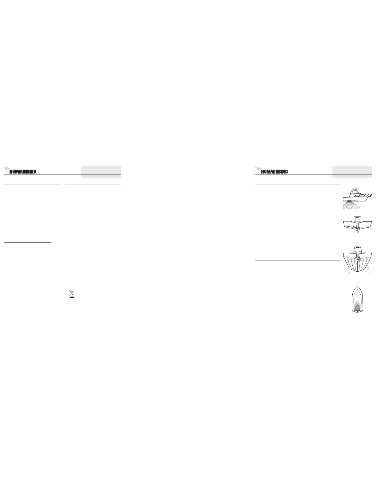
2. Locatingthe TransducerMounting Position
Outside theboat: The bestlocation forthe transducerwill be aftmidship, asclose to thecenterline ofthe boatas
possible.The transducer should bemounted forwardof the propellers oninboard boats,and separated adequately
fromother transducers, strakes,rivet lines,or otherprotrusions.Make surethat there is nothingin front,behind, orto
theside ofthe transducerthat iscloser than12".
Insidethe boat:There mustberoom toaccess themountinglocation forinstallationand cablerouting.
Deadrise:Anotherconsideration istheangle ofdeadrise.
• The transducer,when mounted,shouldpoint straightdown. Iftheselected mountinglocationhas ahull deadrise
of8 degreesor greater,the includedlevelingblock shouldbe usedto levelthetransducer housingand directthe
sonarsignal straightdown.
• If youneed touse theleveling block, make surethat theinside surfaceof thehull is smoothenough toseat the
levelingblock securely.
Thru-Hull Installation
DeadriseAngle
Areas ofPossible Turbulence
Rivets Strakes
Transom Hull
Preferred MountingLocation
Plastic Thru-Hull Side Imaging Transducer
1
531392-1_B
©2008 Humminbird®,EufaulaAL, USA.
Allrights reserved.
Showstransducer closeenough to centerline so
thatthe hull willnot interferewith sideimaging
Maintenance
If yourboat remains inthe water forlong periods of time, algaeand other
m
arine growthcan reduce theeffectiveness of the transducer. Periodically
cleanthe faceof thetransducerwith hotwater.
If yourboat remains out ofthe water fora long periodof time, itmay take
some timeto wet thetransducer afterit is returnedto the water.Small air
bubblescan cling tothe surfaceof the transducer andinterfere withproper
operation.These bubbleswill dissipatewithtime, oryou maywipe thefaceof
thetransducer withyourfingers afterthetransducer isin thewater.
1-Year Limited Warranty
We warrantthe originalretail purchaserthat productsmade byHumminbird®
have beenmanufactured free fromdefects in materials andworkmanship.
This warranty is effe ctive for one year from the date of original retail
purchase.Humminbird® productsfound to bedefective and covered bythis
warrantywill be replacedor repaired free ofcharge at Humminbird® option
andreturned tothe customer freightprepaid. Humminbird®sole responsibility
under this warranty islimited tothe repair orreplacement ofa product that
hasbeen deemeddefective byHumminbird®.Humminbird® isnot responsible
for charges connectedwith the removal ofsuch product orreinstallation of
replacedor repairedparts.
Thiswarranty doesnotapply toa productthathas been:
• Improperly installed;
• Used in an installationother than that recommended in theproduct
installationand operationinstructions;
• Damaged orhas failedbecause ofan accidentor abnormaloperation;
• Repaired ormodifiedby entitiesotherthan Humminbird®.
Pleaseretain youroriginalreceipt asa proofof thepurchasedate. Thiswill be
requiredfor in-warrantyservice.
THIS WARRANTY IS EXPRESSLY IN LIEU OFA NYOTHER WARRANT IES,
OBLIGATIONSOR LIABILITIESON THEPART OFHUMMINBIRD®AND WILLBE
THE CUSTOMER'S EXCLUSI VERE MEDY, EXCEPT FOR ANYA PPLICABLE
IMPLIEDWARRANTIES UNDERSTATE LAWWHICH AREHEREBY LIMITEDIN
DURATIONTO ONE YEAR FROMTHE DATEOF ORIGINALPURCHASE. INNO
EVEN T WILL HUMMI NBIRD® BE L IABLE FOR AN Y INCIDEN TAL OR
CONSEQUENTIAL DAMAGES FORBREACH OF ANY EXPRESSOR IMPLIED
WARRANTYRELATINGTO THEPRODUCTS.
Somestates donot allowlimitations onan impliedwarranty,or theexclusion
of incidental orconsequential damages, so theabove exclusions may not
applyto you.You mayalsohave otherrights,which varyfrom stateto state.
Humminbird® Service Policy
Even though you'llprobably neverneed to takeadvantage of ourincredible
s
ervice policy, it'sgood to know thatwe back ourproducts thisconfidently.
We doit becauseyou deservethe best. We willmake everyeffort to repair
your unit within threebusiness days from the receipt ofyour unit at our
factory. Thisdoes not includeshipping time to andfrom our factory.Units
received onFriday are typically shippedby the followingWednesday, units
receivedMonday aretypicallyshippedby Thursday,etc.
All repairwork is performed byfactory-trained technicians to meetexacting
factory specifications. Factory-servicedunits go through the same rigorous
testingand qualitycontrolinspectionsas newproductionunits.
After the original warranty period, astandard flatrate servicecharge willbe
assesse dfo rea chr epair (physical damag ean dmi ssing parts are not
included). Anyrepairs madeafter theoriginal warrantywill be warrantedfor
an additional 90 days after service has been perfor medb your fact ory
technicians. You can contact our Customer Resource Centeror visit our
website toverify the flat raterepair fee foryour product (visit theProduct
Supportsection):
http://www.humminbird.com
We reserve theright to deem anyproduct unserviceable whenreplacement
parts areno longer availableor impossible to obtain.This Service Policyis
valid inthe United States only.This applies onlyto Humminbird® products
returned toour factory in Eufaula,Alabama.
This ServicePolicy is subject to
changewithout notice.
DOMESTIC (USA)CUSTOMERS:
PLEASE DONOT RETURN THISPRODUCT TO STORE FORSERVICE
Forall technicalissuesplease call1-800-633-1468
Orvisit www.humminbird.com,click SUPPORT
Pleasereferenceproduct serialnumberand
modelnumber whencontactingHumminbird®.
Plastic Thru-Hull Side Imaging Transducer
4
531392-1_B
©2008 Humminbird®,EufaulaAL, USA.
Allrights reserved.
NOTE:A separately-purchasedfairing block canalso beused tocreate a hydrodynamicwaterflow aroundthe transducer
body.The designand fabricationof thisblock variesgreatly withdifferenthull shapes;therefore,it shouldbe customizedby
aqualified marinetechnician.
NOTE:Replacement levelingblocks areavailable fromHumminbird®. Forassistance, contactthe Humminbird®Customer
ResourceCenter atwww.humminbird.comor call1-800-633-1468.
5. Feedthe cablethrough thehole, then temporarilyinstall thetransducerto checkthe fit.
6. Applya generousamountof marine-gradesiliconesealant orslow-curingepoxy insidethe drilledholeand along
themating surfacesof thetransducerhousing. Sealthe matingedges ofthe levelingblock aswell.
7. Makesure thatthe narrow(thin) endof thetransduceris pointingforward.Insert thetransducerinto thedrilled
holefrom outsidethe boat,then installthe nutonto thethreaded stem from insidethe boat.
NOTE:This typeof transduceris directionalin natureand mustbe alignedwith thefrontof theboat (thedirectionof travel)
andparallel tothe centerline. Failureto alignthetransducer properlywill resultin incorrectbottom readingsand incorrect
fishlocations. (SeeIllustrationfororientation).
8. Handtighten thenut ONLYuntil theassemblyis firmlyseated, then tightenNO MOREthan 1/8of aturn extra.
CAUTION:Do notovertightenthe nuttoavoid damage.
Remove the excessadhesive sealant from the outside of the hull to ensure smooth waterflow over the
transducer.
4. Routingthe Cable
Thetransducer cablemust berouted tothe pointwhere thecontrolhead ismounted.
NOTE:Your boatmayhave apre-existingwiring channelorconduit thatyou canusefor thetransducercable.
1. Unplugthe otherend ofthe transducercable fromthe controlhead.
CAUTION!Do notcut or shortenthe transducercable, andtry notto damagethe cableinsulation. Routethe cableas far
aspossible fromany VHFradio antennacables ortachometer cablestoreduce thepossibility ofinterference.If thecable is
too short,extension cablesare availableto extend thetransducer cableup to a total of50'. For assistance,contact the
CustomerResourceCenter atwww.humminbird.comor call1-800-633-1468formore information.
2. Route and secure the cable, avoiding areaswhere it may be damaged or interfere with normal boating
operations.
5. Connectingthe Cable
Insert the transducercable into the appropriate terminalslot. The cable connectors arelabeled, and there are
correspondinglabels on thecable holder onthe rear ofthe control head. Theslots are keyedto prevent reversed
installation,so becarefulnot toforcethe connectorinto theholder.
Yourcontrol headisnow readyfor operation.
Plastic Thru-Hull Side Imaging Transducer
3
531392-1_B
©2008 Humminbird®,EufaulaAL, USA.
Allrights reserved.
SideImaging: Theside imagingtransducer hassomespecial requirementsbecause ofits sideviewing capabilities.
• The side imagingtransducer must not haveanything obstructing the ”view”of the side lookingbeams, i.e.
nothingcan bein thelineof sightof thesebeams(not ahull, motor,or othertransducer,etc).
Note:You mayneedto tiltthe motorup andoutof theway whenusingthe side-lookingbeams.
• In orderfor the side beamsto be displayedaccurately, the transducer mustbe mounted sothat it is looking
straightdown inthewater whenthe boatisin thewater.
Note:Rough seascanalso affectthe readingof theside imagingtransducer.
NOTE:
If theincluded transducerwill not workfor your application, youmay exchange it,NEW and UNASSEMBLED, with
mountinghardware included, fora transducer appropriatefor yourapplication -often atvery littleor nocharge dependingon
the transducer. Call the Humminbird® Customer Resource Center at 1-800-633-1468 for details and pricing, or visit
www.humminbird.com.
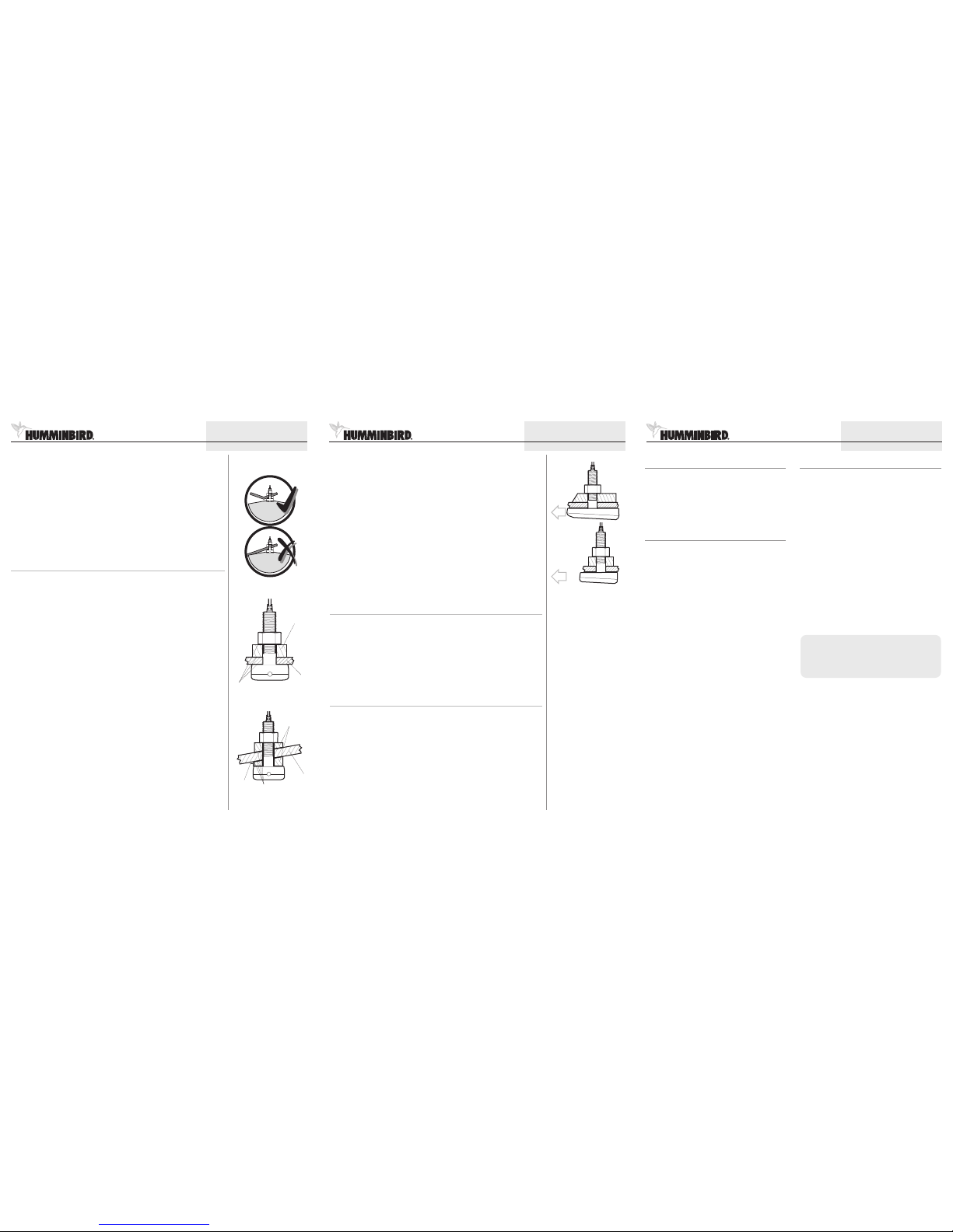
3. Attachingthe Transducer
Beforeattaching yourtransducer, youwillneed todecide whichtype ofinstallationto use:
• For a standard installation,where thereare nomajor obstructions and thedeadriseis less than 8degrees, use
theincluded levelingblock (uncut),andmount itinside thehull.Drill thehole perpendicularto thehull.
• For aninstallation thatneeds tominimizethe impactof asmall obstruction,but wherethe deadriseis lessthan
8 degrees,use theincluded levelingblock (uncut),and mountit outsidethe hull.Drill thehole perpendicularto
thehull.
• For an installationwhere the deadriseis greater than8 degrees, usethe included leveling block,cut at the
appropriateangle,to compensatefor thedeadrise. Drillthehole perpendicularto thewaterline.
1. Fromthe outsideof thehull,drill asmall pilothole(smaller thanthe centeringbit ofyour drillbitor holesaw), at
themounting locationyou selectedin procedure2.
CAUTION: Beforeyou drill, makesure you are drilling inthe correct orientationaccording to theinstallation guidelines
above.
2. Use thepilot hole(from the outsideof the hull) todrill a 11/8" hole thatis sized to fitthe threaded stem of
thetransducer:
NOTE:For installationswherethe deadriseis lessthan 8degrees, whereyou willnot becuttingthe levelingblock, drillthe
holeperpendicularto thehull.
NOTE:For installationswherethe deadriseis greaterthan8 degrees,and youwill becuttingthe levelingblock atan angle,
drillthe holeperpendicularto thewaterline.
3. Thoroughlyclean anddeburrthe drilledhole andclean theoutsideof thehull.
4a. Ifthe deadriseis lessthan 8degrees, youwill notbe cuttingthe levelingblock; install it either onthe inside of
thehull (standardinstallation)or onthe outsideof thehull tocompensatefor smallobstructions.
OR...
4b. Ifthe hullangleis greaterthan8 degrees,youshould cutthe includedleveling blockand useboth piecesto level
thetransducer.The blockshouldbe cutto matchthe angleofthe deadriseofthe hull.Theleveling blockincluded
withyour transducercan accommodatea maximumdeadrise angleof 25degrees.
CAUTION:Use onlythe levelingblock includedwith thistransducer. DoNOT usea woodenlevelingblock, asany swelling
ofthe woodmight causetheplastic onthetransducer toshatter.
NOTE:You shouldcut theleveling blockinto twoequal pieces:one whichmounts outsidethe hulland isshaped tomatch
the profileof the transducer,and one whichmounts inside thehull and providesa level surfacefor the fasteners.The
thinnestwall oftheoutside levelingblockmust beat least1/8".
Cut-levelingblocks
Hull
ApplyMarine Adhesive
Sealantto all matingsurfaces
1/8"
Minimum
thickness
Levelingblock (can
alsobe positioned
outsideof the hull)
Hull
Installationfor deadriseanglegreaterthan8°,
usinga cutlevelingblockto leveltransducer.
Standard Installation
ApplyMarine Adhesive
Sealantto all matingsurfaces
Plastic Thru-Hull Side Imaging Transducer
2
531392-1_B
©2008 Humminbird®,EufaulaAL, USA.
Allrights reserved.
Correct Orientationof TransducerSide Imaging
Showstransducer not closeto centerline, sothat
thehull may interferewith sideimaging
 Loading...