

Page 1
Page 2

Page 3

i
Thank You!
Thank you for choosing Humminbird®, America's #1 name in fishfinders. Humminbird® has built its
reputation by designing and manufacturing top-quality, thoroughly reliable marine equipment. Your
Humminbird® is designed for trouble-free use in even the harshest marine environment. In the unlikely
event that your Humminbird® does require repairs, we offer an exclusive Service Policy - free of charge
during the first year after purchase, and available at a reasonable rate after the one-year period. For
complete details, see the Warranty section in this manual. We encourage you to read this installation and
operations manual carefully in order to get full benefit from all the features and applications of your
Humminbird® product.
Contact our Customer Resource Center at either 1-800-633-1468 or visit our website at
www.humminbird.com.
WARNING! This device should not be used as a navigational aid to prevent collision, grounding, boat damage,
or personal injury. When the boat is moving, water depth may change too quickly to allow time for you to react.
Always operate the boat at very slow speeds if you suspect shallow water or submerged objects.
WARNING! Disassembly and repair of this electronic unit should only be performed by authorized service
personnel. Any modification of the serial number or attempt to repair the original equipment or accessories by
unauthorized individuals will void the warranty. Handling and/or opening this unit may result in exposure to lead,
in the form of solder.
WARNING! This product contains lead, a chemical known to the state of California to cause cancer, birth defects
and other reproductive harm.
NOTE: Some features discussed in this manual require a separate purchase, and some features are only available
on international models. Every effort has been made to clearly identify those features. Please read the manual
carefully in order to understand the full capabilities of your model.
1100 Series™, Cannon™, CannonLink™, HumminbirdPC™, Humminbird®, InterLink™, WeatherSense®, and X-Press™ Menu(s)
are trademarked by or registered trademarks of Humminbird®.
© 2007 Humminbird®, Eufaula AL, USA. All rights reserved.
531615-1_B
Page 4

ii
Table of Contents
1100 Series™ Introduction 1
How GPS and Cartography Work 1
MMC/SD Slot 2
Software Updates........................................................................................................................................ 3
Accessory Bus 3
Video and GPS Output Connectors ............................................................................................................ 3
Installation Overview 4
Control Head Installation 6
Gimbal Mounting the Control Head............................................................................................................ 6
In-Dash Mounting the Control Head ........................................................................................................ 11
Connecting the Control Head Power Cable to the Boat .......................................................................... 14
GPS Receiver Installation 15
Stem Mounting with an Existing 1" - 14 Thread Stem ............................................................................ 15
Access Under Mounting Location ............................................................................................................ 17
No Access Under Mounting Location ...................................................................................................... 17
Finish Routing the Cable and Check GPS Receiver Operation ................................................................ 18
Testing the System Installation 19
Getting Started - Using Your 1100 Series™ 20
Powering Up the Control Head 21
What’s on the Display 22
Key Functions 24
POWER/LIGHT Key .................................................................................................................................... 24
VIEW Key.................................................................................................................................................... 25
MENU Key.................................................................................................................................................. 25
4-WAY Cursor Control Key ........................................................................................................................ 25
View Preset Keys........................................................................................................................................ 26
EXIT Key...................................................................................................................................................... 26
INFO Key .................................................................................................................................................... 26
MARK Key .................................................................................................................................................. 27
GOTO Key.................................................................................................................................................... 27
ZOOM (+/-) Keys........................................................................................................................................ 27
Page 5

iii
Table of Contents
Views 28
Views and Readouts.................................................................................................................................. 28
Bird’s Eye No Readouts View.................................................................................................................... 29
Bird’s Eye View .......................................................................................................................................... 31
Chart/Bird's Eye Combo View.................................................................................................................... 33
Chart/Chart Combo View .......................................................................................................................... 35
Chart No Readouts View .......................................................................................................................... 37
Chart View.................................................................................................................................................. 39
Chart Instrument View ............................................................................................................................ 42
Chart/Bird’s Eye Instrument View ............................................................................................................ 44
Screen Snapshot View .............................................................................................................................. 46
Chart Orientation ...................................................................................................................................... 49
Viewing Cartography 50
Introduction to Navigation 52
Waypoints, Routes and Tracks .................................................................................................................. 52
Save, Edit, or Delete a Waypoint .............................................................................................................. 53
Navigate to a Waypoint or Position .......................................................................................................... 54
Add a Waypoint Target or Trolling Grid .................................................................................................... 55
Save, Edit or Delete a Route .................................................................................................................... 57
Save or Clear a Current Track.................................................................................................................... 57
Edit, Delete or Hide Saved Tracks ............................................................................................................ 58
Man Overboard (MOB) Navigation .......................................................................................................... 58
The Menu System 60
Start-Up Options Menu 63
Normal Operation ...................................................................................................................................... 63
Simulator .................................................................................................................................................. 64
System Status .......................................................................................................................................... 64
Self Test...................................................................................................................................................... 65
Accessory Test............................................................................................................................................ 65
GPS Diagnostic View ................................................................................................................................ 66
Navigation X-Press™ Menu 67
Active Side ................................................................................................................................................ 68
Split Position .............................................................................................................................................. 68
Waypoint [Name]
(only with an active cursor on a waypoint)
.................................................................... 68
Page 6

iv
Cursor to Waypoint
(Chart or Combo view only)
........................................................................................ 69
Save Current Track .................................................................................................................................... 69
Clear Current Track .................................................................................................................................... 70
Save Current Route
(only when navigating)
.............................................................................................. 70
Skip Next Waypoint
(only when navigating)
.............................................................................................. 70
Cancel Navigation
(only when navigating)
................................................................................................ 71
Cancel MOB Navigation
(only when MOB Navigation is activated)
............................................................ 71
Remove Target
(only if a Target is active)
.................................................................................................... 71
Remove Grid
(only if a Grid is active)
.......................................................................................................... 72
Waypoint Name
(most recently-created waypoint)
.................................................................................... 72
Select Readouts ........................................................................................................................................ 73
Select Nav Readouts ................................................................................................................................ 76
Select Instrument Readouts...................................................................................................................... 78
Screen Snapshot X-Press™ Menu
(Screen Snapshot View only) 80
Delete Image
(optional-purchase MMC/SD card only)
................................................................................ 80
Delete All Images
(optional-purchase MMC/SD card only)
........................................................................ 80
Navigation Menu Tab 81
Current Track.............................................................................................................................................. 82
Saved Tracks .............................................................................................................................................. 82
Waypoints .................................................................................................................................................. 83
Routes ........................................................................................................................................................ 84
Chart Orientation ...................................................................................................................................... 84
North Reference ........................................................................................................................................ 85
Trolling Grid Rotation ................................................................................................................................ 85
Trackpoint Interval .................................................................................................................................... 85
Track Min Distance
(Advanced)
................................................................................................................ 86
Track Color Range...................................................................................................................................... 86
Map Datum
(Advanced)
............................................................................................................................ 86
Course Projection Line .............................................................................................................................. 87
3D View Outline ........................................................................................................................................ 87
Export All Nav Data .................................................................................................................................. 87
Delete All Nav Data
(Advanced)
................................................................................................................ 62
Continuous Navigation Mode .................................................................................................................. 62
GPS Receiver Override
(Advanced)
............................................................................................................ 62
Table of Contents
Page 7

v
Table of Contents
Chart Menu Tab 89
Chart Detail Level ...................................................................................................................................... 90
Map Borders .............................................................................................................................................. 90
Lat/Lon Grid .............................................................................................................................................. 91
Spot Soundings.......................................................................................................................................... 91
Navaids on Bird's Eye View ...................................................................................................................... 91
Shaded Depth ............................................................................................................................................ 91
Chart Select................................................................................................................................................ 92
NVB Chart Preference................................................................................................................................ 92
Set Simulation Position
(Advanced)
.......................................................................................................... 92
Set Map Offset
(Advanced)
........................................................................................................................ 93
Clear Map Offset
(Advanced)
.................................................................................................................... 93
Alarms Menu Tab 94
Alarm Volume ............................................................................................................................................ 95
Low Battery Alarm .................................................................................................................................... 95
Temp. Alarm .............................................................................................................................................. 95
Off Course Alarm ...................................................................................................................................... 96
Arrival Alarm .............................................................................................................................................. 96
Drift Alarm.................................................................................................................................................. 97
Setup Menu Tab 98
Sound Volume............................................................................................................................................ 99
Units - Depth.............................................................................................................................................. 99
Units - Temp.
(International only)
.............................................................................................................. 99
Units - Distance
(with Speed input only)
.................................................................................................. 100
Units - Speed
(with Speed input only)
...................................................................................................... 100
User Mode................................................................................................................................................ 100
Language
(International only)
.................................................................................................................. 101
Triplog Reset
(with Speed input only)
...................................................................................................... 101
Restore Defaults ...................................................................................................................................... 101
Temp. Offset
(Advanced)
.......................................................................................................................... 102
Speed Calibration
(Advanced, with Speed paddlewheel only)
.................................................................. 102
Local Time Zone
(Advanced)
.................................................................................................................... 102
Daylight Saving Time
(Advanced)
............................................................................................................ 103
Position Format
(Advanced)
.................................................................................................................... 103
Time Format
(Advanced, International only)
.............................................................................................. 103
Page 8

vi
Table of Contents
Date Format
(Advanced, International only)
.............................................................................................. 104
Digits Format
(Advanced)
........................................................................................................................ 104
NMEA Output
(Advanced)
...................................................................................................................... 104
Demonstration.......................................................................................................................................... 105
IP Address Setup .................................................................................................................................... 105
Video Out
(Advanced)
.............................................................................................................................. 105
Views Menu Tab 106
Accessories Menu Tab 107
Using Screen Snapshot .......................................................................................................................... 108
Troubleshooting 110
Chartplotter Doesn’t Power Up .............................................................................................................. 110
Display Problems 111
Finding the Cause of Noise 111
1-Year Limited Warranty 112
Humminbird® Service Policy 113
Returning Your Unit for Service 114
1100 Series™ Chartplotter Accessories 115
Specifications 116
Glossary 117
Contact Humminbird® 121
NOTE: Entries in this Table of Contents which list (International only) are only available on products sold outside
of the US and Canada by our authorized International Distributors. To obtain a list of authorized International
Distributors, please visit our website at www.humminbird.com or contact our Customer Resource Center at
1-800-633-1468 to locate the distributor nearest you.
NOTE: Entries in this Table of Contents which list (with Speed Input) or (with Temperature Input) may require
the purchase of separate accessories. You can visit our website at www.humminbird.com to order these
accessories online or contact our Customer Resource Center at 1-800-633-1468.
Page 9

1100 Series™ Introduction
Your 1100 Series™ Chartplotter comes in the following configuration:
• Humminbird® 1155c Chartplotter: Networkable GPS Chartplotting System, GPS Receiver
included.
How GPS and Cartography Work
Your 1100 Series™ Chartplotter supports GPS and chartplotting, and uses GPS to determine your position
and display it on a grid. The Global Positioning System (GPS) is a satellite navigation system designed and
maintained by the U.S. Department of Defense. GPS was originally intended for military use; however,
civilians may also take advantage of its highly accurate position capabilities, typically within +/- 10 meters,
depending on conditions. This means that 95% of the time, the GPS receiver will read a location within 10
meters of your actual position. Your GPS Receiver also uses information from WAAS (the Wide Area
Augmentation System), EGNOS (the European Geostationary Navigation Overlay Service), and MSAS (the
MTSAT Satellite Augmentation System) satellites if they are available in your area.
GPS uses a constellation of 24 satellites that
continually send radio signals to the earth. Your
present position is determined by receiving signals
from up to 16 satellites and measuring the distance
from the satellites.
All satellites broadcast a uniquely coded signal
once per second at exactly the same time. The GPS
receiver on your boat receives signals from
satellites that are visible to it. Based on time
differences between each received signal, the GPS
receiver determines its distance to each satellite.
With distances known, the GPS receiver
mathematically triangulates its own position. With
once per second updates, the GPS receiver then
calculates its velocity and bearing.
1
Page 10
The GPS Receiver included with your 1100 Series™ Chartplotter allows you to combine easy-to-use
chartplotter and navigation capabilities. The following GPS functionality is currently supported by the 1100
Series™ Chartplotter when it is connected to the included GPS receiver:
• View current position
• View current track (breadcrumb trail)
• View precision speed and heading from your GPS receiver
• Save tracks, waypoints and routes
• Travel a route and navigate from one waypoint to the next.
Your 1100 Series™ supports Navionics® Gold, HotMaps™, HotMaps™ Premium, and Platinum™
Cartography on MMC or SD card media.
NOTE: Your 1100 Series™ does not support Navionics® Classic Charts, only Navionics® Gold, HotMaps™,
HotMaps™ Premium, and Platinum™ Cartography.
NOTE: Some models come pre-loaded with Navionics® cartography and are referred to as NVB models. NVB
models are only available domestically. Currently, there are not any international NVB models.
In non-NVB models, your unit also comes with a built-in UniMap™ with a detailed map of North America
(Domestic models) or a detailed map of Europe and Southeast Asia, including Australia and New Zealand
(International models). In non-NVB models, the built-in UniMap™ does not contain Port, Tide or Current
information, and this information is only available from optional purchase MMC/SD cards.
Your 1100 Series™ uses the GPS Receiver to determine the position of the boat automatically, and uses
the zoom level settings on a particular view to select the best chart to display. See Viewing Cartography
for more information.
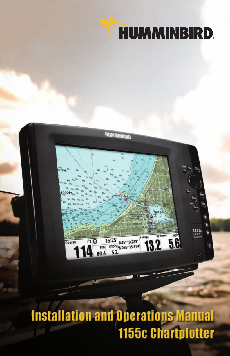
MMC/SD Slot
Your 1100 Series™ Chartplotter also has an MMC/SD slot that is
used to insert optional-purchase cards containing additional
detailed maps. If you insert an MMC/SD that contains a more
detailed chart for a particular location, your 1100 Series™
Chartplotter will retrieve that chart and display it automatically.
Use the illustration to locate the position of the MMC/SD slot
cover, open the MMC/SD slot cover, then insert the MMC/SD
into the slot. The label on the MMC/SD should face toward the
left side of the unit. Press down on the card until it clicks into
place and close the slot cover.
Inserting an MMC/SD into the Card Slot
2
Page 11
Software Updates
Use the MMC/SD slot to update the software version of your control head. To update the software in your
control head, plug in the appropriate MMC/SD card that contains a software update file; the unit will
recognize it, will tell you what software version your control head is currently running, and will ask you if you
want to update the software in the unit to match that on the MMC/SD card. You can obtain software updates
from the www.humminbird.com website.
Accessory Bus
Use the Accessory Bus to expand the functionality of your 1100
Series™. Accessories plug directly into the 1100 Series™, enabling
Advanced features such as WeatherSense and the ®CannonLink™
Downrigger Controller. Additional tabs and menu choices will be
added to the menu system automatically when an accessory is plugged
into the unit. In addition, multiple accessories can be attached
simultaneously. See Accessories Menu Tab and 1100 Series™
Accessories in this manual, as well as your accessory Operations
Manual for additional details.
NOTE: Accessories such as the CannonLink™ Downrigger Controller, InterLink™, and the WeatherSense®
require separate purchases. You can visit our website at www.humminbird.com or contact our Customer
Resource Center at 1-800-633-1468 for additional details.
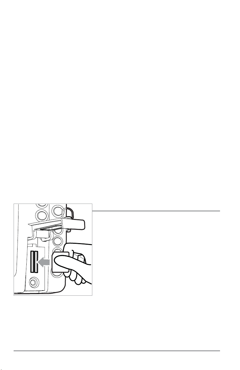
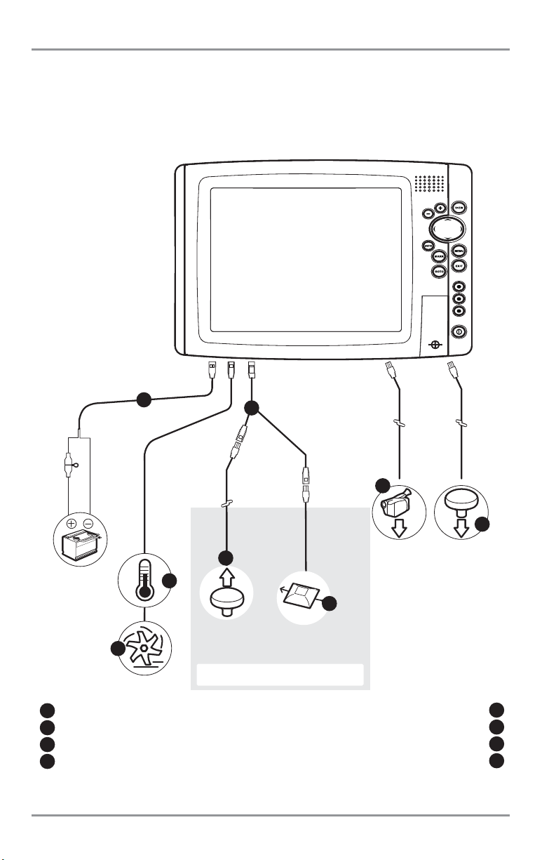
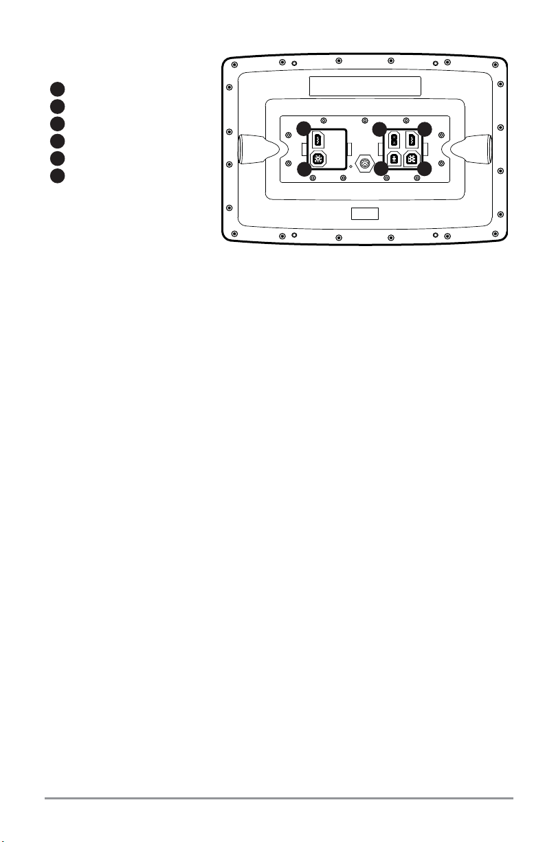
Video and GPS Output Connectors
Your unit comes with a Video Out connector and a GPS Out connector, which can be used with optionalpurchase accessories. For instance, if you purchase a video monitor and attach it to your control head
using the Video Out connector, your unit will automatically send a video signal if it detects a monitor. See
Setup Main Menu: Video Out for more information.
GPS Out
1
Power
2
Communications
3
Video Out
4
Temp/Speed
5
Not Used
6
1100 Series™ Connectors
1
2 3
4
5
6
Accessory Bus
3
Page 12
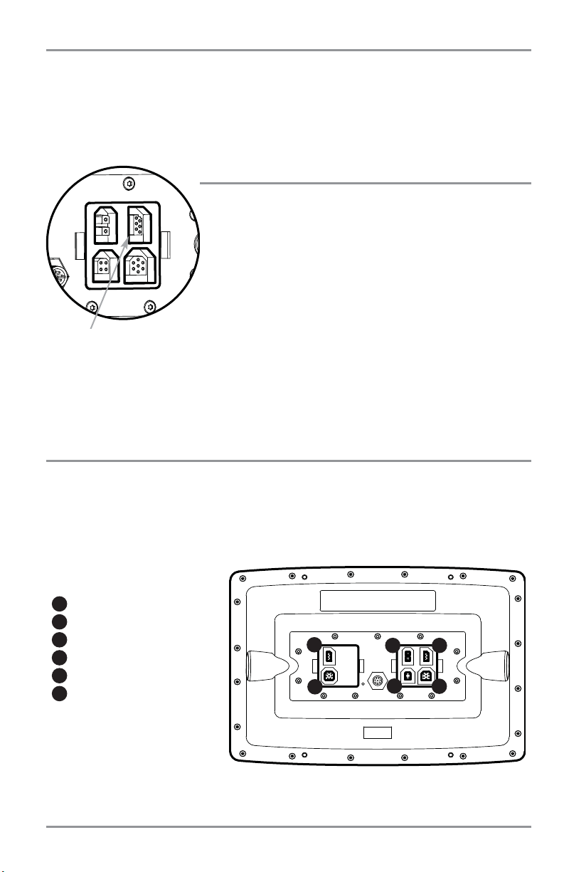
Installation Overview
Please read all instructions that are relevant for your configuration before beginning the installation
process.
NOTE: Installation procedures will depend on product configuration.
Optional “Y” Cable
Power
Temperature
GPS Receiver
WeatherSense®
Video Signal
1
2
3
5
6
7
Speed through water GPS Out
4
8
9
The 1100 Series™ has a wide variety of configurations.
1
2
3
4
5
6
Accessory Bus
7
8
4
Page 13
Inside the boat there is often a channel or conduit used for other wiring, this can be used to route cables.
Be sure to route the cables as far as practical from the antenna cable of VHF radios or tachometer cables
to reduce the possibility of interference. The GPS receiver cable should not be cut, and care should be used
not to damage the cable insulation.
Basic installation tasks that you must perform include:
• Installing the control head (choosing either gimbal or in-dash mounting)
• Installing the GPS Receiver
• Testing the complete installation.
NOTE: Accessories may require a separate purchase. You can visit our website at www.humminbird.com
to order these accessories online or contact our Customer Resource Center at 1-800-633-1468.
GPS Out
1
Power
2
Communications
3
Video Out
4
Temp/Speed
5
Not Used
6
1100 Series™ Connectors
1
2 3
4
5
6
5
Page 14
Control Head Installation
You have two choices for mounting your 1100 Series™ control head, Gimbal mounting, where you use a
surface on the boat, such as the dash, to mount the control head so that it can be tilted up or down, or In-
dash mounting.
Gimbal Mounting the Control Head
If you are gimbal mounting the Humminbird® 1100 Series™, you can pre-assemble the unit in order to plan
the best mounting location.
In addition to the hardware supplied with your control head, you will need a powered hand drill and
various drill bits, various hand tools, including a Phillips head screwdriver, a socket wrench and a flat head
screwdriver, a marker or pencil, safety glasses and dust mask, and marine-grade silicone sealant.
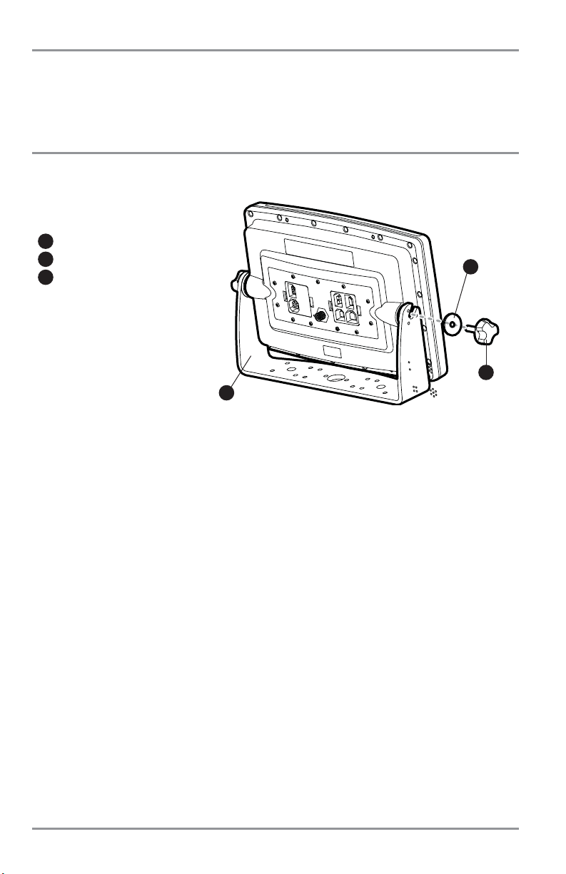
1. Place the control head into the gimbal bracket. Make sure that the straight side of the gimbal arm
is against the back side of the control head.
2. Place a 1" (25 mm) diameter black washer on the gimbal knob and then thread the knob and
washer into the housing. Tighten the gimbal knob to secure the 1100 Series™ control head to the
mount. Repeat step 2 for the other side.
You can now place the control head in various locations to decide which is best for mounting. Rotating the
mounting bracket to the top of the control head will allow for overhead mounting. The chosen mounting
area should allow for sufficient room so the control head can pivot through the full tilt range and allow for
easy removal and installation.
NOTE: You can drill the cable pass hole underneath the gimbal bracket, allowing you to thread the cables through
the large center hole in the mount; however, if you cannot drill the hole directly under the mounting bracket, then
you will need to drill the cable pass hole behind the bracket, and will need to mount the hole cover there instead.
Washer
1
Gimbal Knob
2
Gimbal Mounting Bracket
3
1
2
3
6
Page 15
NOTE: When drilling holes in fiberglass hulls, it is best to start with a smaller bit and use progressively larger drill
bits to reduce the chance of chipping or flaking the outer coating. Fill all holes with marine grade silicone sealant.
NOTE: You must have underside access to the mounting location to pass the cables through to the surface. Also,
make sure that the mounting surface is adequately supported to protect the control head from excessive wave
shock and vibration and provide visibility while in operation.
NOTE: Go to the installation instructions applicable to your GPS Receiver and accessories. Make the required
installations and then run the cables to your control head mounting location. Do not cut any cabling (except the
power cable). If your cables are too short, extensions are available from your local dealer or online from
www.humminbird.com.
3. After the mounting location has been determined, loosen the gimbal knobs and remove the
control head from the gimbal bracket.
NOTE: Alternate hole patterns are available on the gimbal mounting bracket, and may match existing holes on
the boat. You may choose to use one of these alternate hole patterns.
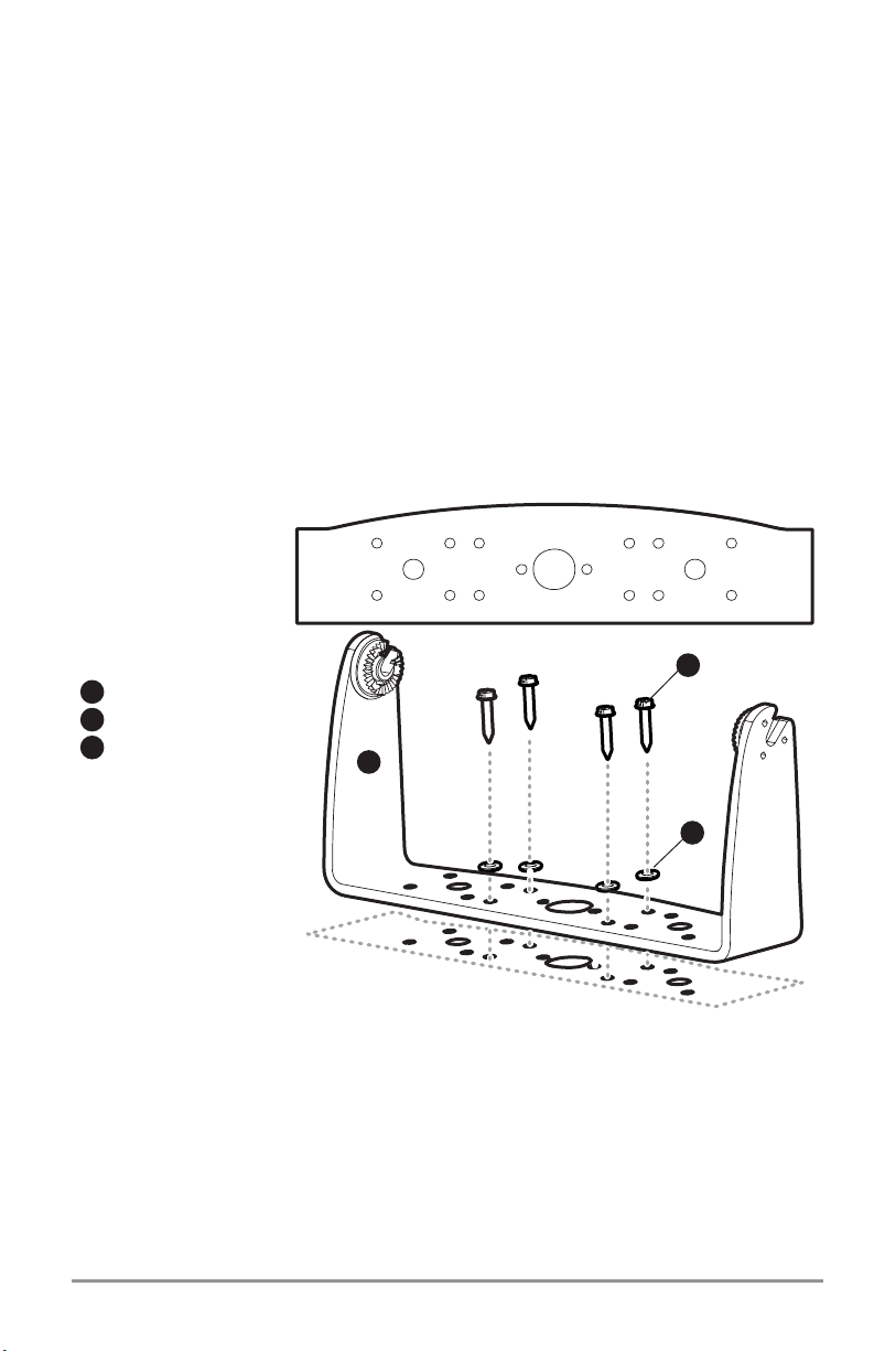
4. Place the gimbal bracket in the chosen position on the mounting surface and mark the four
mounting screw locations using a pencil or center punch.
5. Set the gimbal bracket aside and drill the four mounting screw holes using a 5/32"
(4.0 mm) drill bit.
Mounting Screws
1
Washer
2
Gimbal Mounting Bracket
3
3
2
1
7
Page 16
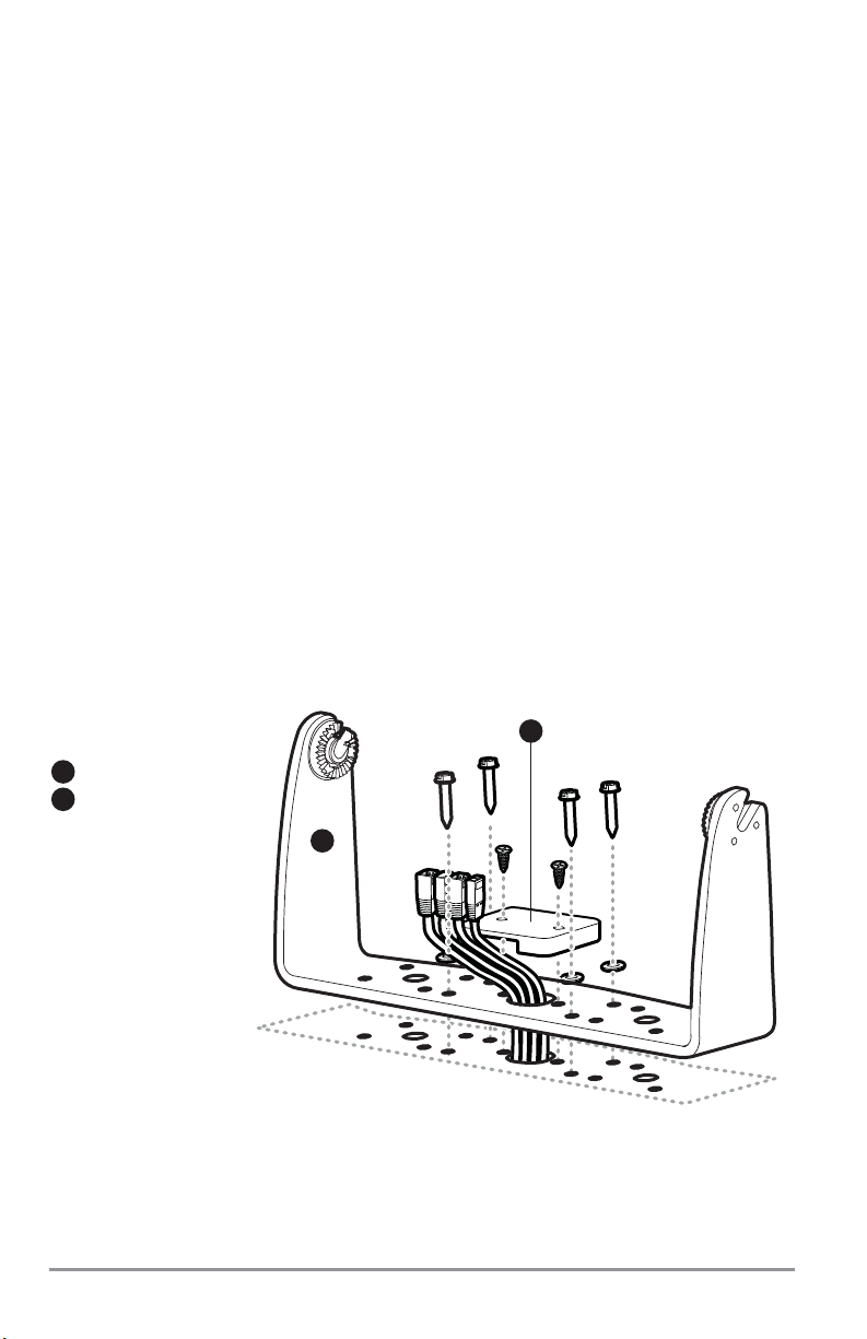
6a. If the cables must pass through a hole directly beneath the mounting bracket, mark and drill an
additional 1" (25 mm) hole centered between the four mounting holes. Route the cables through
the 1" hole. Place the gimbal over the mounting surface hole, then use it to mark the position of
the two mounting screws, closest to the center large hole. Remove the gimbal and drill the two
mounting holes using a 9/64" (3.5 mm) bit. Do not install the hole cover at this time.
or...
6b. If the cables cannot be routed directly beneath the mounting bracket, mark and drill a 1" (25 mm)
hole that will allow you to run the cables close to the bracket. Pass the cables through the 1" (25
mm) hole, routing the cables through the grommet and pressing the grommet into place. Place
the hole cover over the mounting surface hole, then use it to mark the position of the two
mounting screws. Remove the hole cover, drill the two mounting holes using a 9/64" (3.5 mm) bit,
fill them with marine-grade silicone sealant, then replace the hole cover and insert the #8 Phillips
countersink wood screws. Hand-tighten only.
7. Place the mounting bracket on the mounting surface aligned with the drilled holes and fill the
mounting holes with marine grade silicone sealant. Insert the four #10 Slotted-Hex wood screws
into the mounting holes. Hand-tighten only.
8. If the cable pass through hole is beneath the mounting bracket, you will need to install the hole
cover after you have routed all cables. Place the hole cover over the mounting bracket cable pass
thru hole and align with holes drilled in step 6a. Insert the #8 Phillips countersink wood screws.
Hand tighten only.
NOTE: Be sure that the cables pass through the slots on the hole cover and that there is enough cable slack to
allow for the control head to pivot through its full tilt range. Extra cable slack will also help when
connecting/disconnecting the cables.
Gimbal Mounting Bracket
1
Hole Cover
2
1
2
Cables Routed Directly Beneath Mounting Bracket
8
Page 17
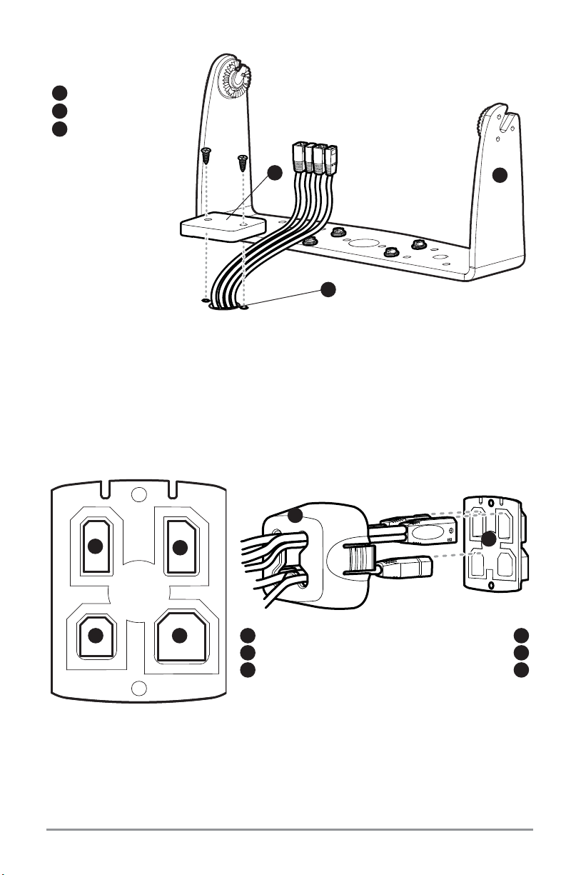
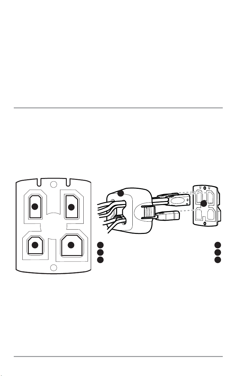
9. Thread the cables through the opening in the back of the cable collector cover.
10. Insert cable connectors into the proper recesses on the cable collector insert. The cable
connectors are keyed to prevent reverse installation, so be careful not to force the connectors into
the wrong slots. If you don’t have a cable for every hole in the insert, install the blank plugs to
protect the control head from the weather.
11. Line up the cable collector insert and cover, with the keying feature, then slide the cover into
place on the insert.
Not Used
Cable Collector Cover
4
5
Cable Collector Insert
6
Inserting the Cables into the Cable Connector Insert
1
2
3 4
Power
Communications
1
2
Temp/Speed
3
5
6
Gimbal Mounting Bracket
1
Grommet
2
Hole Cover
3
1
2
Cables Routed Behind Mounting Bracket
3
9
Page 18
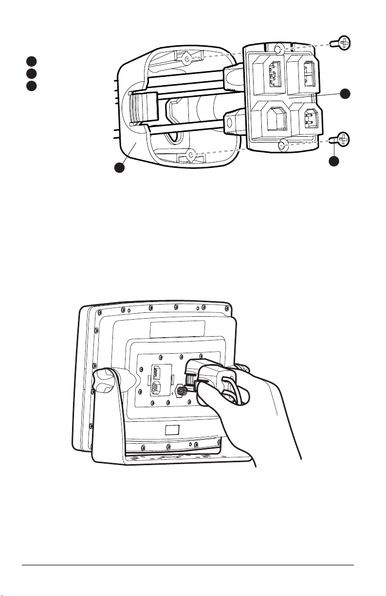
12. Attach the cable collector insert to the cable collector cover using the (2) #6 Phillips screws
provided.
13. Place the control head back onto the mounting bracket. Plug the assembled cable collector into the
back of the control head, pushing gently but steadily until you feel the collector snap into place.
Cable connectors and cable sockets are keyed to prevent reverse installation, so be careful not to
force the connectors into the wrong sockets. Adjust the control head to the desired viewing angle
and secure by tightening the gimbal knobs.
NOTE: You may wish to dress the cabling with nylon wire ties in order to hold the cables together and create a
cleaner assembly.
The Humminbird® 1100 Series™ control head is now ready for operation.
Plugging the Assembled Cable Connector into the Back of the Control Head
Cable Collector Insert
1
Screws
2
Cable Collector Cover
3
Assembling the Cable Collector
3
1
2
10
Page 19
In-Dash Mounting the Control Head
If you are in-dash mounting the control head, start by placing the components on the surfaces where you
intend to install them before installation. Make sure that the surfaces you have chosen provide adequate
protection from wave shock, and that all cables can reach the control head.
NOTE: If a cable is too short for your application, extension cables are available. Call Humminbird® Customer
Support at 1-800-633-1468 for more information.
Parts and tools specific to In-dash mounting are:
• Threaded rods and hardware
• In-dash mounting foam pads
• In-dash mounting template
• Reciprocating saw for cutting dash material
• Masking tape to hold mounting template in place.
1. Locate a suitable, flat area of the dash to mount the control head. The control head requires a
depth of at least 4 inches (102 mm).
2. Tape the paper In-Dash Mounting template to the desired in-dash mounting location.
3. At a location inside the dotted line on the template, drill a hole large enough to insert blade of
reciprocating saw. In addition, drill the 4 mounting hole locations using a 3/16" drill bit. Carefully begin
cutting toward the dotted line, then follow the dotted line around the template. Remove the template
when finished.
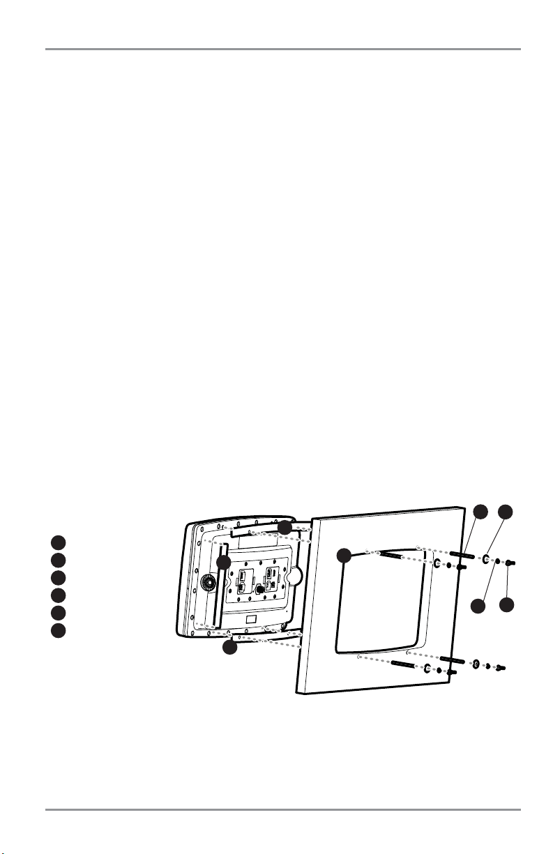
4. Insert and tighten the four threaded rods into the four threaded inserts located on the back side
of the control head. Peel off the adhesive-backed foam pads and place them on the back of the
control head; make sure you notice the difference between the longer top/bottom and shorter
side pads.
Threaded Rod
1
Washer
2
Wing Nut
3
Lock Washer
4
Cut Away Dash
5
Foam Pads
6
1
2
3
5
4
6
6
6
11
Page 20
5. Insert the control head through the mounting hole from the front side of the dash. Place a
washer, lock washer, and wing nut onto each threaded rod and tighten fully.
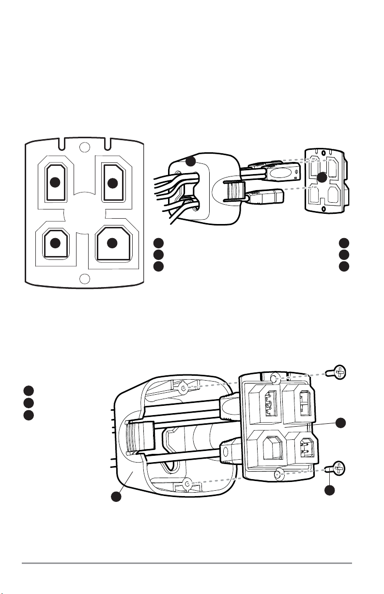
6. Thread the cables through the opening in the back of the cable collector cover.
7. Insert cable connectors into the proper recesses on the cable collector insert. The cable
connectors are keyed to prevent reverse installation, so be careful not to force the connectors into
the wrong slots. If you don’t have a cable for every hole in the insert, install the blank plugs to
protect the control head from the weather.
8. Line up the cable collector insert and cover, with the keying feature, then slide the cover into
place on the insert.
Cable Collector Insert
1
Screws
2
Cable Collector Cover
3
Assembling the Cable Collector
3
1
2
Not Used
Cable Collector Cover
4
5
Cable Collector Insert
6
Inserting the Cables into the Cable Connector Insert
1
2
3 4
Power
Communications
1
2
Temp/Speed
3
5
6
12
Page 21

9. Attach the cable collector insert to the cable collector cover using the (2) #6 Phillips screws
provided.
10. Plug the assembled cable collector into the back of the control head, pushing gently but steadily
until you feel the collector snap into place. Cable connectors and cable sockets are keyed to
prevent reverse installation, so be careful not to force the connectors into the wrong sockets.
NOTE: You may wish to dress the cabling with nylon wire ties in order to hold the cables together and create a
cleaner assembly.
NOTE: It is very important that the cable collector is used and secured in place in the In-Dash installation.
The Humminbird® 1100 Series™ control head is now ready for operation.
13
Page 22
Connecting the Control Head Power Cable to the Boat
A 6' (2 m) long power cable is included to supply power to the control head. You may shorten or lengthen
the cable using 18 gauge multi-stranded copper wire.
CAUTION: Some boats have 24 or 36 Volt electric systems, but the control head MUST be connected to a 12 VDC
power supply.
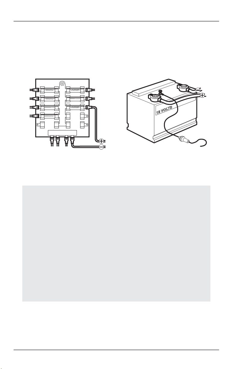
The control head power cable can be connected to the electrical system of the boat at one of two places:
a fuse panel usually located near the console, or directly to the battery.
NOTE: Make sure that the power cable is disconnected from the control head at the beginning of this procedure.
NOTE: Humminbird® is not responsible for over-voltage or over-current failures. The control head must have
adequate protection through the proper selection and installation of a 3 Amp fuse.
NOTE: In order to minimize the potential for interference with other marine electronics, a separate power source
(such as a second battery) may be necessary.
1a. If a fuse terminal is available, use crimp-on type electrical connectors (not included)
that match the terminal on the fuse panel. Attach the black wire to ground (-), and
the red wire to positive (+) 12 VDC power. Install a 3 Amp fuse (not included) for
protection of the unit. Humminbird® is not responsible for over-voltage of overcurrent failures.
or...
1b. If you need to wire the control head directly to a battery, obtain and install an inline
fuse holder and a 3 Amp fuse (not included) for the protection of the unit.
Humminbird® is not responsible for overvoltage or over-current failures.
NOTE: Your unit will detect when your battery voltage is too low or too high, and will display
either Input Voltage Low or Input Voltage High messages if these limits are exceeded. If you
turn the Low Battery Alarm on using the Alarms Main Menu, your unit will use your settings.
If you do not turn the Low Battery Alarm on, the unit will use these limits: 7.5 to 7.9 VDC for
the low end, and 21 to 21.2 VDC for the high end.
GROUND
POSITIVE
14
POSITIVE
GROUND
Page 23

GPS Receiver Installation
To optimize performance of the GPS receiver, mount it in an area that has full exposure to the sky. The
effective area of reception is 10° above the horizon. Different circumstances determine the mounting
method appropriate for your GPS receiver.
If you have… Then use:
The pinouts of the NMEA cable are as follows:
• Red Wire, +12V (output voltage only)
• Black Wire, Ground
• White Wire, NMEA Out.
CAUTION! Please use caution before connecting the red +12V wire to any other NMEA device. This is an output
voltage provided by the control head and GPS receiver and should only be connected to those NMEA devices that
need a 12 volt input.
Stem Mounting with an Existing 1" - 14 Thread Stem
Follow these steps to stem mount the GPS receiver:
NOTE: If you have an existing stem for mounting the GPS receiver, proceed directly to step 2 of the following
procedure.
1. Determine the best location to mount your GPS receiver. Preplan and test the cable routing to
your control head before any drilling or cutting of your boat surfaces. If you have purchased
hardware to stem mount your GPS receiver, follow the instructions included with that hardware
to mount the stem (antenna pole).
NOTE: AS-EC10 10' extension cables are available from Humminbird® if your planned routing exceeds 20', (6 m).
Maximum cable length, including extensions, should not exceed 50' (16 m).
NOTE: Remember to seal screw holes and drilled holes as needed with marine-grade silicone sealant to protect
your boat from water damage.
An existing antenna stem with standard 1" –
14 thread stem
Access for cable routing under the mounting
location
No access under the mounting location
Stem Mount with Existing
1” - 14 Thread Stem
Access Under Mounting Location
No Access Under Mounting Location
15
Page 24
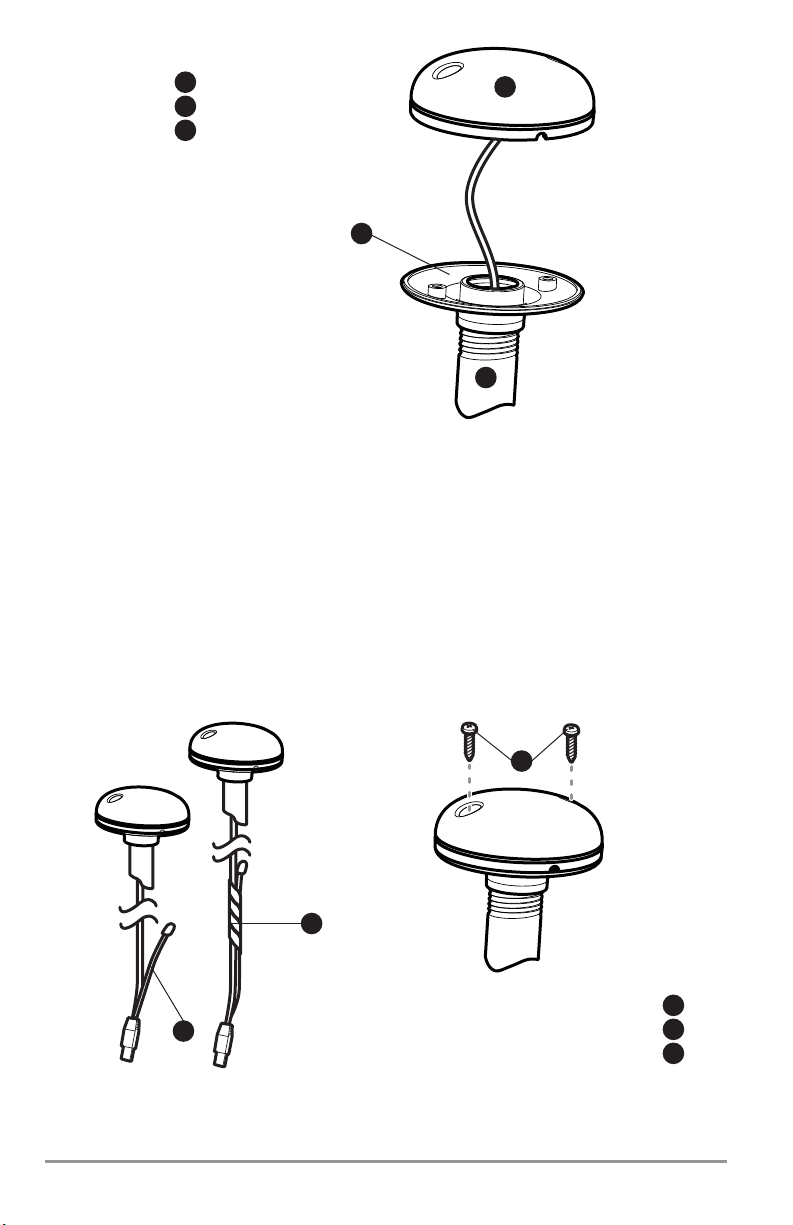
2. Screw on the receiver base to the stem first, making sure that the stem pipe does not protrude
from the receiver base. This adds protection to the cable when pulling it through the pipe stem.
In addition to this, de-burr the pipe edges to reduce cable abrasion.
3. Use electrical tape to secure the NMEA cable to the receiver cable as shown.
NOTE: Leave the NMEA cable secured to the receiver cable unless needed. This will make removing the receiver
easier.
4. Route the GPS receiver cable through the stem and continue with the planned route you chose
in step 1.
5. Attach the GPS receiver to its base using the included #6 - 7/8" screws.
NMEA Cable Taped
NMEA Cable Out
Mounting Screws
1
2
3
1
2
3
Receiver
Receiver Base
1
2
Stem Pipe
3
1
3
2
16
Page 25
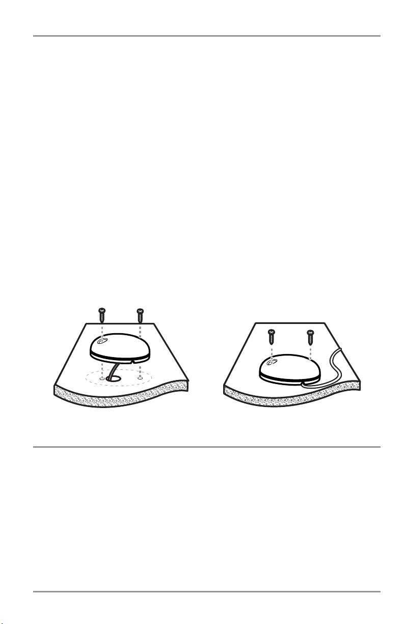
Access Under Mounting Location
Follow these steps to deck mount the GPS receiver when routing the cable down through the mounting
location:
1. Determine the best location, then test route the 20' (6 m) cable from the mounting location to the
control head.
NOTE: Installation details may vary with unit configuration.
2. Mark the mounting location and drill a 3/4" (19 mm) hole for the cable and cable plug. Route the
cable.
3. Cover the cable hole with the receiver. Make sure the receiver is flush on the surface and mark
the two mounting holes with a pencil or punch.
4. Move the receiver to the side and drill two pilot holes using a 9/64" (3.5 mm) bit.
NOTE: Remember to seal screw holes and drilled holes as needed with marine-grade silicone sealant to protect
your boat from water damage.
5. Align the GPS receiver screw holes over the pilot screw holes and attach with the
#8 - 1 1/4" Phillips head screws. Hand tighten only!
NOTE: If the mounting surface is thin and made of a lighter material, a backing material may be needed below
the mounting surface.
No Access Under Mounting Location
Follow these steps to deck mount the GPS receiver in a situation where you must route the cable to the
side because there is no space for a cable underneath the mounting location.
1. Determine the best location, then test route the cable from the mounting location to the control
head.
NOTE: AS-EC10 10' extension cables are available from Humminbird® if your planned routing exceeds 20', (6 m).
Maximum cable length, including extensions, should not exceed 50' (16 m).
2. Confirm the cable length is good and route the cable from the receiver to the control head. If
holes are required to route the cable, they must be 3/4" (19 mm) to allow for the cable connector.
Secure the NMEA cable with electrical tape.
Access Under Mounting Location No Access Under Mounting Location
17
Page 26
NOTE: Remember to seal screw holes and drilled holes as needed with marine-grade silicone sealant to protect
your boat from water damage.
3. The GPS receiver has two wire routing notches. Use the cable notch closest to the intended cable
route.
4. With the cable routed, position the GPS receiver in the planned mounting location and mark the
mounting holes with a pencil or punch.
5. Move the GPS receiver to the side and drill the two 9/64" (3.5 mm) pilot holes.
6. Align the GPS receiver's screw holes over the pilot screw holes and attach with the
#8 - 1 1/4" Phillips head screws. Hand tighten only!
Finish Routing the Cable and Check GPS Receiver Operation
After installing a GPS receiver, you should perform the following procedure to finish routing the GPS cable
to the control head and to check to make sure that the control head is working correctly.
1. Secure the cable along its path to the control head as needed with cable ties.
2. Plug the GPS receiver cable into the Communications port on the control head. See Testing the
System Installation to use the System Status start-up option and/or the GPS Diagnostic View to
confirm a good installation.
Not Used
Cable Collector Cover
4
5
Cable Collector Insert
6
Inserting the Cables into the Cable Connector Insert
1
2
3 4
Power
Communications
1
2
Temp/Speed
3
5
6
18
Page 27

Testing the System Installation
After you have completed the installation of the control head and any other accessories such as the GPS
receiver, and have made all the cabling connections required, you must test the installation before using
the system.
To test the installation:
1. Press the POWER/LIGHT key on the control head once to turn on the control head. (There will be
an audible sound to let you know that you pressed the key, and the initial Title screen will appear.)
If the unit does not power up, make sure that power is available. While the Title screen is shown
on the display, press the MENU key to display the Start-Up Options menu. Use the UP or DOWN
4-WAY Cursor keys to position the cursor, then the RIGHT Cursor key to select System Status from
the Start-Up Options menu (see the Start-Up Options Menu section for more information about
these menu choices). The System Status Self Test screen will appear.
NOTE: If you wait too long, the system will default to whichever menu mode happens to be highlighted, and you
will have to start again.
2. Self Test displays results from the internal diagnostic self test, including unit serial number, Printed
Circuit Board (PCB) serial number, software revision, total hours of operation and the input voltage.
See System Status for more information about the Self Test.
3. From the System Status screen, view accessory connections by pressing the VIEW key. See
System Status for more information about the Accessory Test.
NOTE: The speed will be detected only if the paddlewheel has moved since the 1100 Series™ has been
powered up.
4. From the System Status screen, see a GPS Diagnostic View by pressing the View key. GPS
Diagnostic View shows a sky chart and numerical data from the GPS receiver. The sky chart
shows the location of each visible GPS satellite with its satellite number and a signal strength
bar. A dark gray bar indicates that the satellite is being used to determine your current position.
A light gray bar indicates that the satellite is being monitored, but is not yet being used. See
System Status for more information about the GPS Diagnostic View.
5. You are ready for on the water operation.
19
Page 28
Getting Started - Using Your 1100 Series™
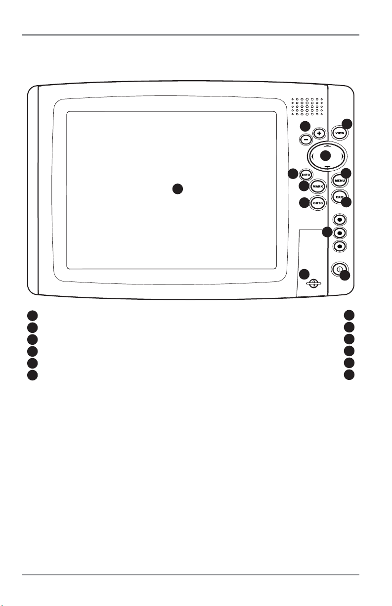
Your 1100 Series™ Chartplotter user interface is easy to use. A combination of keys, different views, and
situation-specific, customizable menus allows you to control what you see on the color display. Refer to
the following illustration, and see Key Functions, Views, and The Menu System for more information.
Screen
ZOOM (+/-) Keys
4-WAY Cursor Control Key
VIEW Key
MENU Key
EXIT Key
1
2
3
7
8
9
INFO Key View Preset Keys
4
10
MARK Key POWER/LIGHT Key
5
11
GOTO Key MMC/SD Card Slot
6
12
7
14
1
2
3
4
5
6
7
8
9
10
11
12
20
Page 29

Powering Up the Control Head
Turn on your Chartplotter by pressing the POWER/LIGHT key. The Title screen is displayed until the
Chartplotter begins operation. After the Title screen is displayed, a 30 second Navigation Warning screen
is shown. Press the MENU key during the time that the Title screen is displayed to view the Start-Up Menu
in order to choose Simulator mode. Press the EXIT key during the Navigation Warning to enter into Normal
mode. If Demonstration is enabled, and you do NOT press the EXIT key, or any other key, during the
Navigation Warning, your Chartplotter will automatically enter Demonstration Mode. Demonstration is
enabled by default, unless you turn it off (see Setup Menu: Demonstration).
1100 Series™ Chartplotter Title Screen
21
Page 30
What’s On the Display
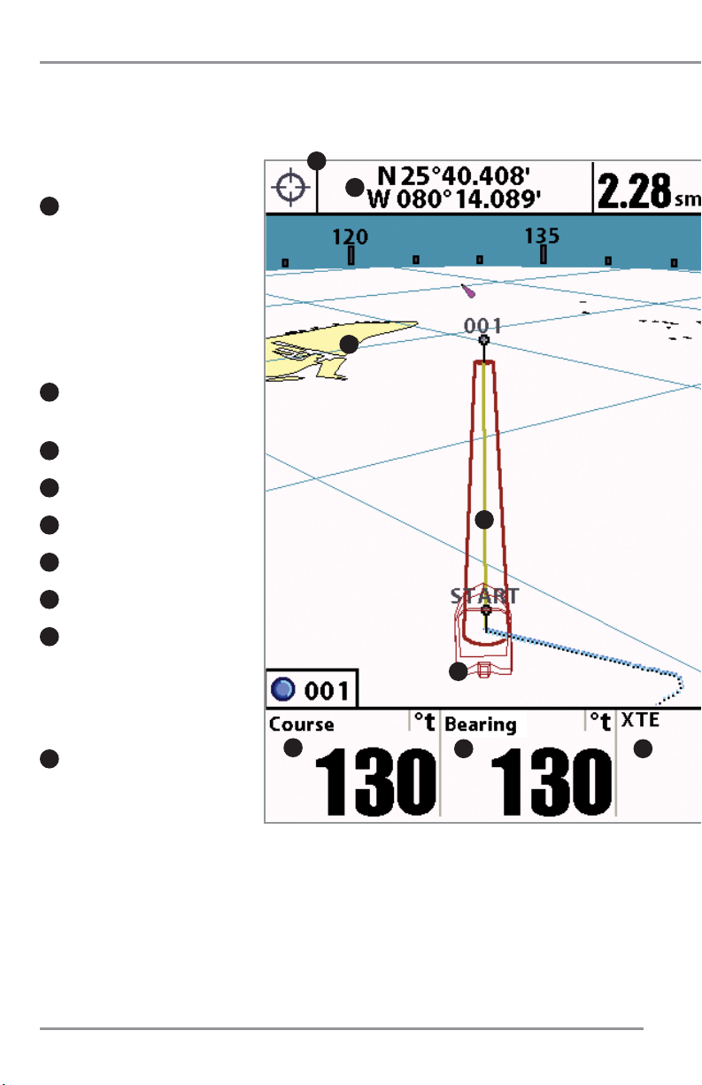
The 1100 Series™ Chartplotter can display a variety of useful information. Chart Bird's Eye Combo View
22
Cursor Info Box: indicates the
Latitude and Longitude of the cursor
position, the distance to travel to the
cursor position and the bearing to the
cursor position is shown with a GPS
receiver. A waypoint can be marked
at the cursor position for later
retrieval and use with a GPS receiver.
Latitude and Longitude
Position of Cursor
Distance: Distance to Cursor
Bearing: Bearing to Cursor
Waypoint
Active Cursor Icon
Boat Icon
Course Projection Line: Arrow
extending from the bow of the boat
that projects your current course, and
shows where the boat will go if you
continue on your present course.
Route: Two or more linked
waypoints that show intended
navigation and the shortest path
from one waypoint to the next.
9
8
7
6
5
4
3
2
1
1
2
7
14
15 16
9
11
Page 31

23
is shown with navigation active.
Track: Detailed position history,
displayed as a breadcrumb trail of
trackpoints.
Cartography
Map Scale
Selectable Readout Boxes
Course: the current direction
the boat is traveling measured in
degrees from North.
Bearing: Bearing to Waypoint
XTE: Cross Track Error
Speed: the measurement of the
boat’s progress across a given
distance; the speed measurement
provided by GPS.
NEXT: Next Waypoint in the Route
TTG: Time to Go to Waypoint
DTG: Distance to Go to Waypoint
20
20
19
18
17
16
15
14
13
12
11
10
3
4
5
6
8
9
10
11
12
13
17
18
19
20
7
Page 32

Key Functions
Your 1100 Series™ user interface consists of a set of easy-to-use keys that work with various on-screen
views and menus to give you flexibility and control over your fishing experience. Your control head has the
following keys:
• POWER/LIGHT key
• EXIT key
• VIEW key
• 4-WAY Cursor Control key
• MENU key
• VIEW PRESET keys.
• MARK key
• GOTO key
• INFO key
• ZOOM (+/-) keys.
POWER/LIGHT Key
The POWER/LIGHT key is used to turn the Chartplotter on and off, and also to adjust the
backlight and background color of the display. Press the POWER/LIGHT key to turn the
unit on. The Title screen is then displayed until the Chartplotter begins operation. See
Powering Up the Unit for a more detailed explanation of the different modes you can
select on power up.
To adjust the backlight or to adjust the display background color,
press the POWER/LIGHT key to access the Light and Background
menu. Use the 4-WAY Cursor key to select Light or Background and
then use the LEFT or RIGHT Cursor key to change the settings. Press
EXIT to exit the Light and Background menu.
Press and hold the POWER/LIGHT key for 3 seconds to turn the unit
off. A message will appear telling you how many seconds there are
until shutdown occurs. Your 1100 Series™ should always be turned
off using the POWER/LIGHT key. This will ensure that shutdown
occurs properly and any menu settings will be saved.
VIEW Key
The VIEW key is used to cycle through all available views. Press the VIEW key to advance
to the next view. Repeatedly pressing VIEW cycles through all views available. Views can
be hidden to optimize the system to your fishing requirements (see View Menu Tab).
24
Page 33

MENU Key
The MENU key is used to access the menu system.
Start-Up Options Menu - Press the MENU key during the power up sequence to view the Start-Up Options
menu.
X-Press™ Menu - Press the MENU key once for the X-Press™ Menu. The X-Press™ Menu allows you to
access frequently-used settings without having to navigate through the whole menu system. When the XPress™ Menu is displayed, you can use the UP or DOWN Cursor keys to move to a particular menu choice.
As soon as you alter a parameter (using the RIGHT or LEFT Cursor keys) the X-Press™ Menu will collapse
temporarily, and the screen will update if it is affected by your menu setting change, allowing you to see
the effects of your action immediately. Reactivate the X-Press™ Menu by using the UP or DOWN Cursor
keys.
Main Menu - Press the MENU key twice for the tabbed Main Menu System. The Main Menu System is
organized under tabbed headings to help you find a specific menu item quickly: Alarms, Navigation, Chart,
Setup, Views, and Accessories tabs are part of your tabbed Main Menu System. Use the LEFT or RIGHT 4WAY Cursor Control key to select a tab; then use the DOWN or UP key to select the menu item, and the LEFT
or RIGHT key to alter a menu setting.
4-WAY Cursor Control Key
The 4-WAY Cursor Control Key has multiple functions, depending on the situation:
Active Cursor - In any Bird's Eye View, the 4-WAY Cursor Control key controls the motion
of the eyepoint. In any Chart View, the 4-WAY Cursor Control key pans the charts.
NOTE: You can also make the cursor move diagonally by pressing in between two of the arrows on the 4-WAY
Cursor Control key.
Menu Selection - Use the DOWN or UP arrow keys to select a menu choice from the menu list, then use
the LEFT or RIGHT arrow keys to change a menu setting.
NOTE: Menu choices are implemented and saved immediately - no further action is required.
VIEW PRESET Keys
The VIEW PRESET keys are used to program your three favorite views for quick retrieval.
Instead of using the VIEW key to cycle through every view to find the one you want, you
can program the VIEW PRESET keys to display a specific view immediately. To program each VIEW PRESET
key, use the VIEW key to cycle to the view you want to store. Press and hold one of the VIEW PRESET keys
for several seconds. A chime will indicate that the view has been saved. You can store up to three views,
one on each key.
25
Page 34

EXIT Key
The EXIT key has multiple functions, depending on the situation:
• If an alarm is sounding, pressing EXIT will cancel the alarm.
• If a menu tab is selected, pressing EXIT will exit the menu mode and return to the view.
• If a menu is active, pressing EXIT will return to the previous level in the menu system.
• Pressing EXIT will cycle through the available views in reverse order.
• If the Cursor is active, pressing EXIT will remove the cursor from the display. Pressing Exit will also
remove any display boxes or waypoint thumbnail views from the screen.
INFO Key
Press the INFO key while in any navigation view to display information about objects that
are nearest to an active cursor.
If the cursor is not active, the following menu will be displayed. Use the
4-WAY Cursor Control key to select Nearest Port, Nearest Tide Station
or Nearest Current Station, then use the RIGHT Cursor key to display
the requested information.
NOTE: In non-NVB models,the built-in UniMap™ does not contain Port, Tide
or Current information, and this information is only available from optional
purchase MMC/SD cards. In NVB models, your units also comes with Port,
Tide or Current information.
On the Chart View, you can use the INFO key to get information on the chart objects near the cursor as
well as to view Screen Snapshots. See Screen Snapshot View for more information.
26
Page 35

MARK Key
Press the MARK key while in any view to mark the position of a waypoint, either at the
current boat location, or, if the Cursor is active, at the current Cursor location.
The MARK key only functions if you have the GPS receiver connected, or if you have
enabled Screen Snapshot from the Accessories menu tab. If you have enabled the Screen Snapshot
feature, pressing the MARK key still creates a waypoint, but it also captures the screen image to the
optional-purchase MMC/SD card and will add a thumbnail to the waypoint.
NOTE: You must have an optional-purchase MMC/SD card installed for the screen snapshot feature to work.
Navigation is not affected by the Screen Snapshot feature. Also, if Screen Snapshot is enabled but there
is no GPS receiver connected, pressing the MARK key will capture the screen image and display an error
saying that a GPS position fix is required to create a waypoint.
GOTO Key
The GOTO Key has multiple functions, depending on the situation:
• If the Cursor is active, pressing the GOTO key while in any view creates a waypoint and starts
navigation towards that waypoint. If the Cursor is not active, pressing the GOTO key displays the
list of waypoints, so that you can select the waypoint towards which you want to navigate.
• If the GOTO key is pressed and held for more than 1.5 seconds, the Man Overboard (MOB) function
is activated. When MOB is activated, an MOB waypoint, which is a permanent, sharable waypoint
with a large, distinctive icon, is created at the boat's current position (regardless of whether the
chart cursor is active or not). Any current navigation will be cancelled and the current route
discarded without user notification, and MOB navigation begins immediately. The view is
switched to the Chart View automatically when MOB is activated, and it is not possible to activate
MOB or modify the current route without first canceling MOB navigation. Any press of the GOTO
key, or selection of a GOTO menu item, will cause an error beep and a short message will be
displayed to the user that will disappear after 2 seconds.
ZOOM (+/-) Keys
Press the - or + ZOOM keys while in any of the Navigation Views to change the scale of
the view to appear closer or farther away.
27
Page 36

Views
The views available on your 1100 Series™ are:
GPS Diagnostic View is the default view until GPS communications are established. At that point, all the
other views become available. When the VIEW key is pressed, the display cycles through the available
views. When the EXIT key is pressed, the display cycles through the available views in reverse order. Any
view can be hidden or displayed as part of the view rotation using the Views Menu tab. See Start-Up
Options Menu for information about the Self Test, Accessory Test, and GPS Diagnostic Views.
NOTE: When you change any menu settings that affect the display, the view will update immediately (i.e. you
don’t have to exit the menu to apply the change to the screen).
Views and Readouts
All views have an Information Bar on the bottom of the screen, consisting of readouts that change from view
to view. You can customize the information displayed in individual readouts on many views, including
suppressing a particular readout so that nothing is displayed; the readouts displayed depend on the view and
whether you are navigating (see Navigation X-Press™ Menu, Select Readouts, Select Nav Readouts, and
Select Instrument Readouts for more information).
• Bird’s Eye No Readouts View
• Bird's Eye View
• Chart/Bird's Eye Combo View
• Chart/Chart Combo View
• Chart No Readouts View
• Chart View
• Chart Instrument View
• Chart/Bird's Eye Instrument View
• Screen Snapshot View
• Self Test View
• Accessory Test View
• GPS Diagnostic View.
Chart/Chart
Combo View
Accessory
Test View
Chart
View
Screen Snaphot
View
Chart
Instrument
View
GPS
Diagnostic
View
Chart/Bird’s Eye
Combo View
Self Test
View
Chart
No Readouts
View
Bird’s Eye
View
Bird’s Eye
No Readouts
View
Chart/Bird’s Eye
Instrument
View
28
Bird’s Eye
Bird’s Eye
No Readouts
No Readouts
View
GPS
GPS
Diagnostic
Diagnostic
View
View
Accessory
Accessory
Test View
Test View
Self Test
Self Test
View
View
Screen Snaphot
Screen Snapshot
View
View
View
Chart/Bird’s Eye
Chart/Bird’s Eye
Instrument
Instrument
View
View
Bird’s Eye
Bird’s Eye
View
View
Chart
Chart
Instrument
Instrument
View
View
Chart/Bird’s Eye
Chart/Bird’s Eye
Combo View
Combo View
Chart/Chart
Chart/Chart
Combo View
Combo View
Chart
Chart
No Readouts
No Readouts
View
View
Chart
Chart
View
View
Page 37

Bird's Eye No Readouts View
Bird's Eye No Readouts View shows a 3D perspective view like all the other Bird's Eye Views, but without
readouts. See Bird's Eye View for more information.
Track
3
Cartography
4
Bird's Eye No Readouts View (Standard)
1
2
3
4
Waypoint
1
Boat Icon
2
29
Page 38

Route
5
Track
6
Boat Icon
7
Bird's Eye No Readouts View (Navigating)
1
2
3
4
Cartography
1
Waypoint
2
Arrival Alarm Limits
3
Off Course Limits
4
5
7
6
30
Page 39

Bird's Eye View
Bird's Eye View shows a 3D perspective view of the track and the chart land contour from a point above
and behind the boat (the eye point).
As the boat turns, the eye point moves to follow the boat. When you press the 4-WAY Cursor key in any of the
Bird’s Eye Views, the position of the eye point will shift. This allows you to move and turn the eye point so that
you can look off to the sides, or even behind the boat. Pressing the RIGHT or LEFT arrow keys on the 4-WAY Cursor
key turns the eye point right or left, while pressing the UP arrow key moves the eye point forward, and pressing
the DOWN arrow key moves the eye point backward.
Pressing the EXIT key moves the eye point back to its original position behind and above the boat.
NOTE: Only the standard configuration readouts are shown in the graphics. Readouts can be customized to suit
your needs.
NOTE: If all selectable readout boxes are turned off below the Bird's Eye pane, the window will stretch
to fill the whole vertical pane. See Navigation X-Press™ menu: Select Readouts for more information.
Course:
the current direction the boat is traveling
measured in degrees from North.
Time
Latitude and Longitude
Position of Boat
VLT:
Voltage
Boat Icon
Cartography
1
2
3
Speed:
the measurement of the boat’s progress across a
given distance; the speed measurement provided by GPS.
4
5
6
7
Waypoint
8
Bird's Eye View (Standard)
1
2
3
4
5
6
7
8
31
Page 40

NOTE: If there is only one waypoint in a route, the Next Waypoint and the End Waypoint info boxes will display
the same information.
Bearing:
Direction to Destination Waypoint
measured in degrees from North
3
Course:
the current direction the boat is traveling
measured in degrees from North.
2
Next Waypoint
1
Speed:
the measurement of the boat’s progress across a
given distance, and is the speed measurement provided by GPS.
5
NEXT:
Next Waypoint in the Route
6
TTG:
Time to Go to Waypoint
7
DTG:
Distance to Go to Waypoint
8
Track
9
Boat Icon
10
Route
11
Cartography
12
Bird’s Eye View (Navigating)
XTE (Cross Track Error):
Distance of Boat from Route
4
1
1
2
3 4
5
6
7
8
9
10
11
12
32
Page 41

Chart/Bird’s Eye Combo View
Chart/Bird’s Eye Combo View shows both the Chart and Bird’s Eye views in a combination split screen. You
can perform any of the functions for either of these views, but only when the view you want to control
is selected as the active side (see Navigation X-Press™ Menu: Active Side for more information). A green
arrow points to the side that is active. You can also adjust the size of the left side of a split screen
(see Navigation X-Press™ Menu: Split Position for more information).
NOTE: See Bird’s Eye Views and Chart Views for more information about each side of this view.
NOTE: Only the standard configuration readouts are shown in the graphics. Readouts can be
customized to suit your needs.
Chart/Bird’s Eye Combo View (Standard)
Course:
the current direction the boat is traveling
measured in degrees from North.
Time
Latitude and Longitude
Position of Boat
VLT:
Voltage
Cartography
Map Scale
1
2
3
Speed:
the measurement of the boat’s progress across
a given distance; the speed measurement provided by GPS.
4
5
6
7
Boat Icon
8
Course Projection Line
9
3D View Outline
10
1
2
3
4
5
6
6
7
8
8
9
10
33
Page 42

Bearing:
Direction to Destination Waypoint
measured in degrees from North
3
Course:
the current direction the boat is traveling
measured in degrees from North.
2
Next Waypoint
1
Speed:
the measurement of the boat’s progress across a given distance;
the speed measurement provided by GPS.
5
NEXT:
Next Waypoint in the Route
6
TTG:
Time to Go to Waypoint
7
DTG:
Distance to Go to Waypoint
8
Chart Window
9
Cartography
10
Map Scale
11
Boat Icon
12
Route
13
Bird’s Eye Window
14
Chart/Bird’s Eye Combo View (Navigating)
XTE (Cross Track Error):
Distance of Boat from Route
4
1
2
3
4
5
6
7
8
9
10
10
11
12
12
14
1
13
13
1
34
Page 43

Chart/Chart Combo View
Chart/Chart Combo View shows two versions of the Chart view in a combination split screen, so that you can
see the position of the boat on one side while you zoom in or perform other functions on the other. You can
perform any of the functions for the Chart view, but only on the side of the view you have selected as the active
side (see Navigation X-Press™ Menu: Active Side for more information). A green arrow points to the side
that is active. You can also adjust the size of the left side of a split screen (see Navigation X-Press™ Menu:
Split Position for more information).
NOTE: See Chart Views for more information about each side of this view.
NOTE: Only the standard configuration readouts are shown in the graphics. Readouts can be customized to suit
your needs.
Chart/Chart Combo View (Standard)
Course:
the current direction the boat is traveling
measured in degrees from North.
Time
Latitude and Longitude
Position of Boat
Cartography
Course Projection Line
Waypoint
1
2
3
Speed:
the measurement of the boat’s progress across
a given distance; the speed measurement provided by GPS.
4
VLT:
Voltage
5
6
7
8
Map Scale
9
Boat Icon
10
Track
11
1
2
3
4
5
6
6
7
10
9
8
9
11
11
10
7
8
35
Page 44

NOTE: All views except the Bird's Eye/Chart Instrument View share the same set of 5 selectable readouts that
can all be set one way for navigation mode and another way for non-navigation mode. When you change the
readout displays on one of these views, you also are changing them on all the other views that share the same
configuration. See Navigation X-Press™ menu: Select Readouts and Select Nav Readouts for more
information.
Bearing:
Direction to Destination Waypoint
measured in degrees from North
3
Course:
the current direction the boat is traveling
measured in degrees from North.
2
Next Waypoint
1
Speed:
the measurement of the boat’s progress across
a given distance; the speed measurement provided by GPS.
5
NEXT:
Next Waypoint in the Route
6
TTG:
Time to Go to Waypoint
7
DTG:
Distance to Go to Waypoint
8
Route
9
Course Projection Line
10
Boat Icon
11
Tra ck
12
Map Scale
13
Cartography
14
Chart/Chart Combo View (Navigating)
XTE (Cross Track Error):
Distance of Boat from Route
4
1
2
3
4
5
6
7
8
1
11
11
12
12
13
13
14
14
1
10
9
9
36
Page 45

Chart No Readouts View
Chart No Readouts View shows cartography like all the other Chart Views, but without readouts. See
Chart Views for more information.
Map Scale Waypoint
1
Cartography
2
Course Projection Line
3
4
Boat Icon
5
Track
6
Chart No Readouts View (Standard)
1
2
3
4
5
6
37
Page 46

Map Scale Route
1
Cartography
2
Course Projection Line
3
Next Waypoint
4
5
Boat Icon
6
Track
7
Chart No Readouts View (Navigating)
1
2
3
4
5
6
7
38
Page 47

Chart View
Chart Views - The standard Chart, Chart No Readouts, and Chart/Chart Combo Views, as well as the Chart
side of the Chart/Bird's Eye Combo View and the Chart/Bird's Eye Combo Instrument View, all show
cartography from the built-in UniMap™ or an optional MMC/SD map for the area surrounding your current
position. The current track (also known as the position history or breadcrumb trail) showing where the boat
has been, along with saved tracks, waypoints, and the current route (when navigating), are overlaid on the
chart. You can use the 4-WAY Cursor Control key to shift/pan the chart to another area. You can use the
ZOOM (+/-) keys to zoom in and out. You can use the INFO key to get information on the chart objects near
the cursor as well as to view Screen Snapshots.
NOTE: Only the standard configuration readouts are shown in the graphics. Readouts can be customized to suit
your needs.
Chart View (Standard) with optional-purchase Navionics® Cartography
Course:
the current direction the boat is traveling
measured in degrees from North.
Time
Latitude and Longitude
Position of Boat
Cartography
Declutter Icons
Boat Icon
1
2
3
Speed:
the measurement of the boat’s progress across
a given distance; the speed measurement provided by GPS.
4
VLT:
Voltage
5
6
7
8
Track
9
Course Projection Line
10
Waypoint
11
Map Scale
12
1
2
3
4
5
6
7
8
9
10
11
12
39
Page 48

NOTE: All views except the Bird's Eye/Chart Instrument View share the same set of 5 selectable
readouts that can all be set one way for navigation mode and another way for non-navigation mode.
When you change the readout displays on one of these views, you also are changing them on all the
other views that share the same configuration. See Navigation X-Press™ menu: Select Readouts
and Select Nav Readouts for more information.
NOTE: Your Chart screen will automatically declutter and simplify as you zoom out. When you zoom out, all
waypoint icons that might otherwise overlap each other will declutter the screen by changing into very small blue
icons, and individual waypoint names will be hidden. When you're panning, and your cursor snaps to a waypoint
that is using the declutter icon, that waypoint will display its full-size icon and name temporarily (until you move
the cursor off of it). In addition, when a waypoint name will write on top of another waypoint, the name will be
truncated until the cursor snaps to it. Different waypoints will use the declutter feature at different zoom levels.
Chart View (with Cursor) with optional-purchase Navionics® Cartography
Cursor Info Box
Boat Icon
1
Latitude and Longitude
Position of Cursor
2
Distance:
Distance to Cursor
3
Bearing:
Bearing to Cursor
4
Cartography
5
Waypoint
6
Cursor
7
Declutter Icons
8
Course Projection Line
9
10
Track
11
Map Scale
12
Course:
the current direction the boat is traveling
measured in degrees from North.
13
1
2
3
4
5
6
7
10
11
12
Time
14
Latitude and Longitude
Position of Boat
15
Speed:
the measurement of the boat’s progress across
a given distance; the speed measurement provided by GPS.
16
VLT:
Voltage
17
13
14
15
16
17
9
8
40
Page 49

NOTE: You may also choose Chart No Readouts View if you prefer.
Bearing:
Direction to Destination Waypoint
measured in degrees from North
3
Course:
the current direction the boat is traveling
measured in degrees from North.
2
Next Waypoint
1
Speed:
the measurement of the boat’s progress across
a given distance; the speed measurement provided by GPS.
5
NEXT:
Next Waypoint in the Route
6
TTG:
Time to Go to Waypoint
7
DTG:
Distance to Go to Waypoint
8
Boat Icon
9
Route
10
Course Projection Line
11
Track
12
Cartography
13
Map Scale
14
Chart View (Navigating) with optional-purchase Navionics® Cartography
XTE (Cross Track Error):
Distance of Boat from Route
4
1
2
3
4
5
6
7
8
9
10
1
12
14
13
11
41
Page 50

Chart Instrument View
Chart Instrument View displays a digital panel at the top of the screen. This view provides a digital
compass, XTE graphic, and up to 10 readouts.
NOTE: Only the standard configuration readouts are shown in the graphics. Readouts can be customized to suit
your needs.
Course:
the current direction the boat is traveling
measured in degrees from North.
Voltage
1
Latitude and Longitude
Position of Boat
2
Speed:
the measurement of the boat’s progress across
a given distance; the speed measurement provided by GPS.
3
Timer:
Elapsed time with Speed accessory or
GPS Receiver.
Distance:
Distance traveled with Speed accessory
or GPS Receiver.
Average Speed:
Average speed reading with Speed
accessory or GPS Receiver.
4
5
Cartography
6
Track
7
Boat Icon
8
Waypoint
9
Course Projection Line
10
Compass
11
XTE (Cross Track Error):
Distance of Boat from Route
12
Map Scale
13
Chart Instrument View (Standard)
1
2
3
4
5
6
8
11
7
TRIPLOG
9
10
12
13
42
Page 51

NOTE: If there is only one waypoint in a route, the Next Waypoint and the End Waypoint info boxes will display
the same information, both for that next waypoint..
XTE (Cross Track Error):
Distance of Boat from Route
1
Compass
2
Cartography
3
Course Projection Line
4
Next Waypoint
5
Boat Icon
6
Track
7
Map Scale
8
ETA:
Estimated time of arrival
14
DTG:
Distance to Go to Waypoint
15
Speed:
the measurement of the boat’s progress across
a given distance; the speed measurement provided by GPS.
16
17
Chart Instrument View (Navigating)
9
10
11
12
13
14
15
16
1
17
18
19
20
21
2
1
3
Bearing:
Direction to Destination Waypoint
measured in degrees from North
9
Course:
the current direction the boat is traveling
measured in degrees from North.
10
Time
11
Latitude and Longitude
Position of Boat
12
END:
Last waypoint in the route
13
5
5
8
Timer:
Elapsed time with
Speed accessory or GPS Receiver.
Distance:
Distance traveled with
Speed accessory or GPS Receiver.
Average Speed:
Average speed reading
with Speed accessory or GPS Receiver.
TRIPLOG
NEXT:
Next Waypoint in the Route
18
TTG:
Time to Go to Waypoint
19
DTG:
Distance to Go to Waypoint
20
Voltage
21
4
6
7
43
Page 52

Chart/Bird's Eye Instrument View
Chart/Bird's Eye Instrument View displays a digital instrument panel at the top of the screen. This view
provides a digital compass, XTE graphic, and up to 10 readouts.
NOTE: Only the standard configuration readouts are shown in the graphics. Readouts can be customized to suit
your needs.
Course:
the current direction the boat is traveling
measured in degrees from North.
Chart Window
1
Time
2
Latitude and Longitude
Position of Boat
3
Speed:
the measurement of the boat’s progress across
a given distance; the speed measurement provided by GPS.
4
Timer:
Elapsed time with Speed accessory
or GPS Receiver.
Distance:
Distance traveled with Speed accessory
or GPS Receiver.
Average Speed:
Average speed reading with Speed
accessory or GPS Receiver.
5
6
Waypoint
7
Boat Icon
8
Map Scale
9
Track
10
Cartography
11
Compass
12
XTE (Cross Track Error):
Distance of Boat from Route
13
Bird’s Eye Window
14
Chart/Bird’s Eye Instrument View (Standard)
1
2
3
4
5
8
6
9
11
11
10
14
8
10
12
TRIPLOG
7
13
7
44
Page 53

NOTE: If there is only one waypoint in a route, the Next Waypoint and the End Waypoint info boxes
will display the same information, both for that next waypoint.
Bearing:
Direction to Destination Waypoint
measured in degrees from North
1
Course:
the current direction the boat is traveling
measured in degrees from North.
2
XTE (Cross Track Error):
Distance of Boat from Route
3
Time
4
NEXT:
Next Waypoint in the Route
5
TTG:
Time to Go to Waypoint
6
DTG:
Distance to Go to Waypoint
7
Latitude and Longitude
Position of Boat
8
Timer:
Elapsed time with Speed accessory
or GPS Receiver.
Distance:
Distance traveled with Speed accessory
or GPS Receiver.
Average Speed:
Average speed reading with Speed
accessory or GPS Receiver.
9
END:
Last waypoint in the route
11
ETA:
Estimated time of arrival
12
DTG:
Distance to Go to Waypoint
13
VLT:
Voltage
14
Chart Window
15
Waypoint
16
Map Scale
17
Boat Icon
18
Route
19
Cartography
20
Compass
21
Bird’s Eye Window
22
Chart/Bird’s Eye Instrument View (Navigating)
Speed:
the measurement of the boat’s progress across a
given distance; the speed measurement provided by GPS.
10
TRIPLOG
1
2
3
4
5
6
7
8
9
10
11
12
13
14
15
16
17
18
18
19
20
20
21
22
3
19
16
45
Page 54

Screen Snapshot View
Screen Snapshot View displays and allows you to view screen snapshot thumbnails captured to an
optional-purchase MMC/SD card installed in your unit. In addition, when you are in the Screen Snapshot
View, Delete Image and Delete All Images are added to the X-Press™ menu.
The Screen Snapshot View displays up to three screen snapshot thumbnails on the screen at a time; you
may have to scroll using the 4-WAY Cursor keys to see the whole list of thumbnails in this view. The
selected thumbnail will be highlighted with arrows.
NOTE: The speed of the screen capture depends on the type of card you use; in general, SD cards
capture the screen faster than MMC cards do.
Screen Snapshot: When Screen Snapshot is enabled (from the Accessories menu tab), pressing the MARK
key creates a saved screen capture (when you have an optional-purchase MMC/SD card installed). Once
you have created a screen capture, a screen capture thumbnail is added to the Screen Snapshot View, and
is available to view at a later date. See the full-sized image by highlighting a thumbnail (using the Up or
Down 4-Way Cursor keys), then using the Right 4-Way Cursor key to view the full image. A border around
the full-size screen snapshot indicates that it is just a screen snapshot, not a “live” view. You can delete
the selected image, or all images, by selecting a thumbnail and using Delete Image, or using Delete All
Images from the Screen Snapshot X-Press™ menu.
W
orking with screen snapshots is a four-step process:
1. Enabling Screen Snapshot from the Accessories Menu.
2. Making a Screen Snapshot using the MARK key.
3. Viewing a Screen Snapshot using the Screen Snapshot View.
4. Deleting a Screen Snapshot using the Screen Snapshot X-Press™ menu.
46
Page 55

For more information, see Accessories Menu Tab: Using Screen Snapshot and Screen Snapshot
X-Press™ Menu.
Waypoint Thumbnails: On the Chart View, you can use the INFO key to view Screen Snapshot as Waypoint
thumbnails. Waypoints thumbnails are created while the Snapshot feature is turned on. They are linked to
snapshot waypoints. Before these snapshot waypoints are edited for the first time, they are assigned a
filename that begins with an S and is followed by several numbers, and are represented by the camera icon.
NOTE: You must have an MMC/SD card installed to store or view waypoint thumbnails. If you press the INFO
key while the cursor is on a snapshot waypoint and the MMC/SD card is missing, only the normal chart
information will be displayed.
When the cursor is active on the Chart View and snaps to one of these snapshot waypoints, a waypoint
thumbnail will be displayed. Pressing the INFO key while the cursor is near one of these snapshot
waypoints will make the full snapshot appear on the screen. Pressing the EXIT key will show the cursor on
the waypoint, with the waypoint thumbnail displayed.
Highlighted Screen Snapshot Thumbnail Time and Date where Snapshot was captured
1
Screen Snapshot Thumbnail
2
Unavailable icon
3
Information Box
4
Snapshot Name
5
6
Position where Snapshot was captured
7
Amount of space left on the card
8
Total amount of space on card
9
Screen Snapshot View
1
2
3
5 6 7
8
9
4
47
Page 56

When you start a screen snapshot, you will see a message that a waypoint has been created at the point
where your cursor is on the screen, and the screen will freeze while the snapshot is being saved to the
MMC/SD card. A status dialog box will appear that shows the progress of the save as a percentage, and
that displays the numbered file name assigned to the .BMP file that is being created. Snapshot filenames
begin with the letter "S". For more information, see the Accessories Menu Tab: Using Screen Snapshot
procedure and Screen Snapshot X-Press™ Menu.
Chart View showing the Waypoint Thumbnail Feature
Course:
the current direction the boat is traveling
measured in degrees from North.
11
Bearing:
Direction to Destination Waypoint
measured in degrees from North
12
Speed:
the measurement of the boat’s progress across
a given distance; the speed measurement provided by GPS.
14
1
Cursor Info Box
1
Latitude and Longitude
Position of Cursor
2
Distance
to Cursor
3
Bearing
to Cursor
4
Route
5
Boat Icon
6
Snapshot Waypoint Name
7
Waypoint Thumbnail
8
Map Scale
9
Next Waypoint
10
2 3
4
10
5
7
8
9
10
XTE (Cross Track Error):
Distance of Boat from Route
13
11
12
13
14
NEXT:
Next Waypoint in the Route
15
TTG:
Time to Go to Waypoint
16
DTG:
Distance to Go to Waypoint
17
15
16
17
6
48
Page 57

Chart Orientation
All the chart views allow you to choose the orientation of the chart. When North-Up orientation is selected,
True North is shown at the top of the display. In other words, objects located to the north of the boat are drawn
above the boat. When Course-Up orientation is selected, the direction of motion of the boat is shown at the
top of the display. In other words, objects ahead of the boat are drawn above the boat. In both orientations,
the view pans automatically, so that the boat is always centered on the display. When the boat is stationary,
it is drawn as a circle. When the boat is in motion, it takes on a boat shape, pointed in the direction of motion
(always Up in the Course-Up orientation). See Navigation Menu Tab: Chart Orientation for more information.
49
Page 58

Viewing Cartography
In the Chart or Combo Views, there are several cartography-related functions that you can access using
various keys.
Panning: Use the 4-WAY Cursor keys to move the chart around on the display in the direction of the key being
pressed. When you do this, a Bullseye Cursor is drawn at the top of the screen and is linked to the boat by a
yellow line, even if the boat is off the screen. At the same time, a cursor dialog box is displayed at the top of
the screen with the distance and bearing from the boat to the cursor position and the latitude/longitude
coordinates of the cursor. When the cursor is active on the display, you can also use the 4-WAY Cursor Control
key to move the cursor diagonally.
Zooming: Use the Plus (+) key to Zoom In and the Minus (-) key to Zoom Out showing the cartography at
different scales. The scale is indicated on the left side of the display. If you zoom in beyond the available
chart data, the display will go into Overzoom mode whereby the last available chart data is amplified to
reflect the scale selected. If you zoom in so far that no cartography is available, a lat/lon grid will be drawn
instead.
NOTE: Your Chart screen will automatically declutter and simplify as you zoom out. When you zoom out, all
waypoint icons that might otherwise overlap each other will declutter the screen by changing into very small blue
icons, and individual waypoint names will be hidden (see Chart View). When you're panning, and your cursor
snaps to a waypoint that is using the declutter icon, that waypoint will display its full-size icon and name
temporarily (until you move the cursor off of it). In addition, when a waypoint name will write on top of another
waypoint, the name will be truncated until the cursor snaps to it. Different waypoints will use the declutter
feature at different zoom levels.
Chart View with Cursor Present
50
Page 59

Chart Info: Use the INFO key to get detailed information about the chart. If the cursor is active, you will
see information about the chart objects located near the cursor. If the cursor is not active, the Chart Info
menu will appear. You can select the nearest port, the nearest tide station, or the nearest current station
to see information about any of these objects using the 4-WAY Cursor Control key.
NOTE: The built-in UniMap™ does not contain any Port, Tide or Current information. This information is only
available from optional-purchase MMC/SD cards.
Screen Snapshot Waypoints: Use the INFO and 4-WAY Cursor Control keys to view screen snapshot
thumbnails. On the Chart View, you can use the INFO key to view Screen Snapshot waypoints. Snapshot
waypoints are waypoints that are created while the Snapshot feature is turned on. See Screen Snapshot
View for more information.
Screen Snapshots: Use the INFO and 4-WAY Cursor Control keys to view thumbnails of your Screen
Snapshots using snapshot waypoints. Snapshot waypoints are waypoints that are created while the
Snapshot feature is turned on. See Screen Snapshot View for more information.
NOTE: You must have an MMC/SD card installed to store or view waypoint thumbnails. If you press the INFO key
while the cursor is on a snapshot waypoint and the MMC/SD card is missing, only the normal chart information
will be displayed.
Nearest Port: The position and services information for the nearest port to your present position will be
displayed. Press the EXIT key to remove the information box and the Bullseye Cursor will be centered over the
port position. The Cursor Information Boxes will indicate the distance and bearing to the port from your present
position. Press the EXIT key again to return to the Chart View.
Nearest Tide Station: Tide information for the nearest tide station to your present position will be
displayed. This includes the position of the station and the times of the high and low tides for today’s date.
A tide graph is also displayed showing the rise and fall of the tides for the 24 hour time period
encompassing the date. You can change the date to look at tide information before or after the date
displayed by pressing the LEFT or RIGHT Cursor key respectively. Press the EXIT key to remove the
information box and the Bullseye Cursor will be centered over the tide station position. The cursor
information boxes will indicate the distance and bearing to the tide station from your present position.
Press the EXIT key again to return to the Chart View.
Nearest Current Station: Current information for the nearest current station to your present position will
be displayed. This includes the position of the station and the current changes for today. Two graphs are
also presented that show the time, direction and flow speed of the current changes for the 24 hour time
period of today’s date. You can change the date to look at current information before or after the date
displayed by pressing the LEFT or RIGHT Cursor key respectively. Press the EXIT key to remove the
information box and the Bullseye Cursor will be centered over the current station position. The Cursor
Information Boxes will indicate the distance and bearing to the current station from your present position.
Press the EXIT key again to return to the Chart View.
51
Page 60

Introduction to Navigation
Use the 1100 Series™ to establish waypoints at areas of interest and to navigate to those waypoints via a
saveable route (representing the shortest intended distance between waypoints). You can also view and
save tracks, which represent the actual path of the boat.
Waypoints, Routes and Tracks
Waypoints are stored positions that allow you to mark areas of interest or navigation points. Your 1100
Series™ can store up to 3000 waypoints.
Bearing:
Direction to Destination Waypoint
measured in degrees from North
3
Course:
the current direction the boat is traveling
measured in degrees from North.
2
Next Waypoint
1
Speed:
the measurement of the boat’s progress across
a given distance; the speed measurement provided by GPS.
5
NEXT:
Next Waypoint in the Route
6
TTG:
Time to Go to Waypoint
7
DTG:
Distance to Go to Waypoint
8
Cartography
9
Track
10
Off Course Limits
11
Boat Icon
12
Course Projection Line
13
Arrival Alarm Limits
14
Map Scale
15
Waypoints, Routes and Tracks
XTE (Cross Track Error):
Distance of Boat from Route
4
1
2
3
4
5
6
7
8
9
11
10
13
15
1
14
12
52
Page 61

Routes link two or more waypoints together to create a path for navigation, and are used in trip planning.
You can link individual waypoints together by using the GOTO key. A route represents your intended
navigation and shows the shortest path from each waypoint to the next. As you travel a route, staying on
the route line is the most efficient way to get to your destination, although you should always look out for
obstacles not shown on the chart. Your 1100 Series™ can store up to 50 routes that can each contain up
to 50 waypoints.
Tracks consist of detailed position history, and are displayed as a breadcrumb trail of trackpoints. The
Current Track shows the position history since the unit was powered up (maximum of 20,000 trackpoints
displayed). You can clear the Current Track or save it at any time. Your 1100 Series™ can store up to 50
saved tracks, each containing 20,000 trackpoints. The current track represents your actual path so far.
Save, Edit, or Delete a Waypoint
Save your current position as a waypoint: On any view, press the MARK key to save the current position
of the boat as a waypoint.
Save the cursor position as a waypoint: On the Chart or Combo view, use the Cursor key to designate the
position you want to save as a waypoint. Then press the MARK key to save the marked position as a waypoint.
Save a position from the sonar history: Use the Cursor key to point to a feature in the sonar history (also
called the Sonar Saver feature). Press the MARK key to create a waypoint at the location where that sonar
reading was taken. The new waypoint will also record the depth at that location.
NOTE: When you save a waypoint by any of these methods, a numerical waypoint name is automatically
assigned. You can edit the waypoint information later to give it a different name and select an icon to represent
it (see Waypoint submenu on the Navigation Main Menu Tab).
Display the Waypoints Submenu: From any view, press the MENU key twice to display the Main Menu
System, then use the RIGHT Cursor key to select the Navigation tab. Select Waypoints and press the RIGHT
Cursor key to display the Waypoints submenu.
Program a specific position as a waypoint: To create a waypoint that is NOT your current position, from
the Waypoints submenu, select the Create option and press the RIGHT Cursor key. Use the Cursor keys to
program a waypoint name, latitude, longitude, and icon before selecting Save.
Edit a waypoint: From the Waypoints submenu, select Edit and press the RIGHT Cursor key to display a
list of saved waypoints. Select the waypoint you want to edit and press the RIGHT Cursor key. Use the 4WAY Cursor Control key to move from field to field, and the UP and DOWN Cursor keys to changes values
once you are in a field. In the Waypoint Name, Latitude and Longitude fields, use the UP and DOWN
Cursor keys to change the letter or number. All upper and lower case letters are available, as well as digits
0-9 and some punctuation characters. In the Waypoint Icon field, use the UP and DOWN Cursor keys to
change the icon used to represent the waypoint on the Combo and Chart Views. You can exit these fields
with the LEFT and RIGHT Cursor keys or by pressing the EXIT key. Select Save and press the RIGHT Cursor
key to save your changes.
53
Page 62

To make it easier to select a waypoint, select Sort By and press the RIGHT or LEFT Cursor keys to select a
sort order:
• Name shows the waypoints alphabetically
• Time shows the most recently-created waypoint first
• Distance shows the closest waypoint first.
Delete a waypoint: From the Waypoints submenu, select Delete and press the RIGHT Cursor key to display
a list of waypoints. Select the waypoint you want to delete, then press the RIGHT Cursor key. You will be
asked to confirm deletion before the waypoint is actually deleted.
Navigate to a Waypoint or Position
Navigate to the cursor position: From any Chart or Combo view, use the Cursor key to select a position or
waypoint to which you want to navigate. Press the GOTO key. Navigation will begin immediately.
Navigate to a specified waypoint: Press the GOTO key, then choose the waypoint to which you would like
to navigate from the waypoint list and press the RIGHT Cursor key to select it.
NOTE: By repeating the previous instructions, you can add more waypoints to create a longer multi-segment
route.
Skipping a waypoint: From the Navigation X-Press™ Menu, select Skip Next Waypoint and press the
RIGHT Cursor key. If there is not another waypoint to skip to, navigation will be cancelled.
Cancel navigation: From the Navigation X-Press™ Menu, select Cancel Navigation and press the RIGHT
Cursor key. Canceling navigation removes the route and any waypoints created using the GOTO key, but
does not remove any saved routes from memory. You will be prompted to save the current route when you
cancel navigation.
54
Page 63

Add a Waypoint Target or Trolling Grid
Add or Remove a Waypoint Target: From the Waypoints submenu (accessed from the Navigation main
menu), select Target and press the RIGHT Cursor key to display a list of waypoints. Select the waypoint you
want to target. A target consisting of concentric circles centered on the selected waypoint will appear on
all of the navigation views; the target shows various distance ranges from the targeted waypoint. To
remove the target, choose Remove Target from the Navigation X-Press™ Menu.
NOTE: Only one waypoint can have either a target or a grid at one time. If you apply a target or a grid to a new
waypoint, the original waypoint will lose its target or grid.
Bearing:
Direction to Destination Waypoint
measured in degrees from North
3
Course:
the current direction the boat is traveling
measured in degrees from North.
2
Next Waypoint
1
Speed:
the measurement of the boat’s progress across
a given distance; the speed measurement provided by GPS.
5
NEXT:
Next Waypoint in the Route
6
TTG:
Time to Go to Waypoint
7
DTG:
Distance to Go to Waypoint
8
Cartography
9
Track
10
Waypoint Target
11
Boat Icon
12
Route
13
Waypoint
in declutter mode
14
Map Scale
15
Chart View with Target
XTE (Cross Track Error):
Distance of Boat from Route
4
1
2
3
4
5
6
7
8
9
11
12
10
13
14
15
55
Page 64

Add or Remove a Trolling Grid: From the Waypoints submenu (accessed from the Navigation main menu), select
Grid and press the RIGHT Cursor key to display a list of waypoints. Select the waypoint to which you want to add
the grid. The trolling grid will appear on all of the navigation views, and can be used as a guide when trolling
around a waypoint. The grid can be rotated to any desired heading using Grid Rotation from the Navigation Main
menu. To remove the trolling grid, choose Remove Grid from the Navigation X-Press™ Menu.
NOTE: Only one waypoint can have either a target or a grid at one time. If you apply a target or a grid to a new
waypoint, the original waypoint will lose its target or grid.
NOTE: The spacing of the rings on the waypoint target and the spacing of the grid lines on the trolling grid is the
same as the length of the scale bar on the left edge of the display. Zooming in or out will decrease or increase
the spacing, respectively.
Bearing:
Direction to Destination Waypoint
measured in degrees from North
3
Course:
the current direction the boat is traveling
measured in degrees from North.
2
Next Waypoint
1
Speed:
the measurement of the boat’s progress across
a given distance; the speed measurement provided by GPS.
5
NEXT:
Next Waypoint in the Route
6
TTG:
Time to Go to Waypoint
7
DTG:
Distance to Go to Waypoint
8
Cartography
9
Track
10
Waypoint Trolling Grid
11
Boat Icon
12
Route
13
Waypoint
in declutter mode
14
Map Scale
15
Chart View with Grid
XTE (Cross Track Error):
Distance of Boat from Route
4
1
2
3
4
5
6
7
8
9
11
12
10
14
15
13
56
Page 65

Save, Edit or Delete a Route
Save the current route: While you are navigating, the current route can be saved. From the Navigation
X-Press™ Menu, select Save Current Route and press the RIGHT Cursor key. Navigation will continue.
Display the Routes submenu: From any view, press the MENU key twice to display the Main Menu
System, then use the RIGHT Cursor key to select the Navigation tab. Select Routes and press the RIGHT
Cursor key to display the Routes submenu.
Create a route: From the Routes submenu, select Create and press the RIGHT Cursor key.
A Route Edit screen will be displayed with an empty route. You can name the route, add waypoints to
the route from the list of all waypoints, and order the waypoints in the route using the Cursor keys.
Edit a saved route: From the Routes submenu, select Edit and press the RIGHT Cursor key.
A Route Edit screen will be displayed. Select the route you wish to edit and press the RIGHT Cursor key.
Re-name the route or change, delete or re-order the waypoints used in the route.
Delete a saved route: From the Routes submenu, select Delete and press the RIGHT Cursor key. Select
the route you wish to delete and press the RIGHT Cursor key. You will be asked to confirm your choice
by pressing the RIGHT Cursor key again before the route is deleted.
Travel a saved route: From the Routes submenu, select Travel and press the RIGHT Cursor key. A list of
saved routes will appear. Select the route you wish to travel and press the RIGHT Cursor key to make
this route the current route and begin navigation. You may also travel the route in either forward or
reverse order.
Route Info: From the Routes submenu, select Info and press the RIGHT Cursor key. A list of saved routes
will appear. Select the route for which you want information, and press the RIGHT Cursor key. The list
of waypoints in the route will be shown, with the distance and bearing from each waypoint to the next,
as well as the distance and bearing from the current position to the first waypoint in the route.
Save or Clear a Current Track
Save the current track: From the Navigation X-Press™ Menu, select Save Current Track and press the
RIGHT Cursor key. The track will remain on the display, but will change from black to gray. To remove the
track completely from the display, see Edit, Delete or Hide Saved Tracks.
NOTE: When you save a track, a name is automatically assigned. The track name consists of a date/time stamp,
but can be re-named later (see Edit, Delete, or Hide Saved Tracks).
Clear the current track: From the Navigation X-Press™ Menu, select Clear Current Track and press the
RIGHT Cursor key. The track will be removed from the display and discarded.
57
Page 66

Edit, Delete or Hide Saved Tracks
Display the Tracks Submenu: From any view, press the MENU key twice to display the Main Menu
System, then use the RIGHT Cursor key to select the Navigation tab. Select Tracks and press the RIGHT
Cursor key to display the Tracks submenu.
Edit a saved track: From the Tracks submenu, select Edit and press the RIGHT Cursor key to display the
list of saved tracks. Select the track you want to edit and press the RIGHT Cursor key. When the Edit Track
dialog box appears, use the Cursor keys to move between fields. In the Track Name field, the UP and
DOWN Cursor keys change the letter or number. All upper and lower case letters are available, as well as
digits 0-9 and some punctuation characters. You can exit the Track Name field with the LEFT and RIGHT
Cursor keys or by pressing the EXIT key. Select Save and press the RIGHT Cursor key to save your changes.
Delete a saved track: From the Tracks submenu, select Delete and press the RIGHT Cursor key to display
the list of saved tracks. Select the track you want to delete and press the RIGHT Cursor key. You will be
asked to confirm deletion before the track is actually deleted.
Hide or display a saved track: From the Tracks submenu, select Visibility and press the RIGHT Cursor key
to display the list of saved tracks. Select the track you want to hide or display and use the Cursor keys to
select Hidden or Visible. Press the EXIT key to return to the Tracks submenu.
Man Overboard (MOB) Navigation
As soon as you know that you have a man overboard, you should activate MOB navigation to maximize
chances for a successful rescue. MOB navigation allows you create a MOB waypoint to locate the point at
which your man went overboard, and the relation of the boat to that point. When MOB is activated, a MOB
waypoint, which is a permanent, sharable waypoint with a large, distinctive icon, is created at the boat's
current position (regardless of whether the chart cursor is active or not). Any current navigation will be
cancelled and the current route discarded without user notification, and MOB navigation will begin
immediately. A line will be drawn from the boat's current position to the MOB waypoint, and the MOB
waypoint will be targeted. The view is switched to the Chart View automatically when MOB is activated,
and an additional info box that shows the lat/lon position of the MOB waypoint and the elapsed time since
MOB was activated is added to the Chart View.
It is not possible to re-activate MOB or modify the current route without first canceling MOB navigation.
The Off Course trigger is also disabled and the Off Course Alarm circle is not drawn. Any press of the GOTO
key, or selection of a GOTO menu item, will cause an error beep and a short message will be displayed to
the user that will disappear after 2 seconds.
58
Page 67

Activate MOB navigation: Press and hold the GOTO key for more than 1.5 seconds to activate the Man
Overboard (MOB) function.
Cancel MOB navigation: From the Navigation X-Press™ menu, select Cancel MOB and press the RIGHT
Cursor key. Canceling MOB navigation removes the route and any waypoints created using the GOTO key,
but does not remove any saved routes from memory.
Course:
the current direction the boat is traveling
measured in degrees from North.
6
Target
Surrounding MOB Waypoint
1
MOB Waypoint
2
Boat Icon
3
Position
where Man Overboard was activated
4
Elapsed Time
since MOB was activated
5
NEXT:
Next Waypoint in the Route
10
TTG:
Time to Go to Waypoint
11
DTG:
Distance to Go to Waypoint
12
Speed:
the measurement of the boat’s progress across
a given distance; the speed measurement provided by GPS.
9
MOB Navigation
6
7
8
9
10
11
12
1
2
3
4
5
XTE (Cross Track Error):
Distance of Boat from Route
8
Bearing:
Direction to Destination Waypoint
measured in degrees from North
7
59
Page 68

The Menu System
The menu system is divided into easy-to-use menu modules. The main components of the menu system
are:
Start-Up Options Menu: Press the MENU key during the power up sequence to view the Start-Up Options
menu. See Start-Up Options Menu.
X-Press™ Menu: The X-Press™ Menu allows you to access the
settings that are changed frequently without having to navigate
through the whole menu system. Press the MENU key once to
display the X-Press™ Menu. When you select a menu item from
the X-Press™ Menu, the menu will collapse, leaving only the
menu choice on the screen. Use the UP or DOWN Cursor keys to
reactivate the X-Press™ Menu.
NOTE: The X-Press™ Menu choices will vary depending on which
view is active when you press the MENU key, as well as whether you
are in Normal or Advanced User Mode. Either the Navigation or Screen
Snapshot X-Press™ Menu will appear, depending on the view you are
in.
Main Menu Tabs: Less frequently-adjusted menus are grouped
into the Main Menu System. The Main Menu system is organized
under main tab menu headings to help you find a specific menu
item quickly. Main tab headings are: Alarms, Navigation, Chart,
Setup, Views, and Accessories.
Navigating Through the Main Menu Tabs: To change an
individual menu setting, use a combination of the MENU and the
4-WAY Cursor Control keys, as follows:
1. Press the MENU key twice to display the Main Menu.
2. Use the 4-WAY Cursor LEFT or RIGHT key to select a
specific menu tab.
3. Use the DOWN or UP 4-WAY Cursor Control key to
select a specific menu item under that tab.
4. Use the LEFT or RIGHT keys again to change a menu
setting.
X-Press™ Menu
60
Page 69

QUICK TIPS:
• When your cursor is within a menu tab, press the EXIT key to jump directly to the top of the tab.
• If you are at the bottom of a menu tab, press the DOWN Cursor key to jump directly to the top of
the tab.
• If you're at the left or right of a menu tab, you can also jump to the other side by pressing the LEFT
or RIGHT cursor keys repeatedly until you have moved past the end of the menu.
• A down arrow at the bottom of a menu means that you can scroll to additional menu choices using
the DOWN Cursor key.
• A right or left arrow on a menu choice means that you can use the RIGHT or LEFT Cursor keys to
make changes or to see more information.
• If you press MENU or EXIT to leave the main menu system, and then you return to the main menu
using the MENU key, you will be at the same main menu tab you were on when you last displayed
the main menu.
Total Screen Update: When you change any menu settings that affect the view you are in, the view will
update immediately (i.e. you don’t have to exit the menu to apply the change to the screen).
User Mode (Normal or Advanced): The Main Menu choices will vary depending on whether you are in
Normal or Advanced User Mode. An Advanced Mode is provided for users who desire the highest level of
control over the 1100 Series™ and Normal Mode for users who desire greater simplicity and fewer menu
choices. Additional Advanced menu choices will be displayed throughout the menu system when you navigate
to specific menus while in Advanced Mode. Any changes made while in Advanced Mode will remain in effect
after you switch back to Normal Mode. See Setup Menu Tab: User Mode for specific instructions on changing
to the User Mode.
NOTE: The 1100 Series™ defaults to Advanced User Mode on start-up.
61
Page 70

Setup Tab, Normal User Mode
Setup Tab, Advanced User Mode
62
Page 71

Start-Up Options Menu
Press the MENU key when the Title screen is displayed to access the Start-Up Options menu.
Use the UP or DOWN 4-WAY Cursor keys to position the cursor, then the RIGHT Cursor key to select one
of the following choices. If you wait too long, the system will default to whichever menu mode happens
to be highlighted:
• Normal
• Simulator
• System Status.
See the following paragraphs for more information about each of these choices.
Normal Operation
Use Normal Operation for on the water operation. Turn on your Chartplotter by pressing the
POWER/LIGHT key. The Title screen is displayed until the Chartplotter begins operation. After the Title
screen is displayed, a 30 second Navigation Warning screen is shown. Press the MENU key during the time
that the Title screen is displayed to view the Start-Up Menu in order to choose Simulator mode.
Press the EXIT key during the Navigation Warning to enter into Normal mode.
Start-Up Options Menu
63
Page 72

Simulator
Use the Simulator to learn how to use your 1100 Series™ before taking your boat on the water. The Simulator
is a very powerful tool that simulates on-the-water operation, providing a randomly-updated display. We
recommend going through this manual while using the Simulator, since all of the menus function and affect
the display the way they actually do when in Normal operation.
NOTE: At startup, while still on the Title screen (while the name of your Humminbird® model is still on the screen)
you must press the MENU key and then select Simulator manually to enter Simulator mode. Manually selecting
Simulator from the Start-Up Options menu allows you to pre-configure your Chartplotter for on the water
operation. Any menu changes you make will be saved for later use.
A Simulation message will appear on the display periodically to remind you that you are using the
Simulator.
Exit the Simulator by powering your 1100 Series™ off.
System Status
Use System Status to view system connections and to conduct a unit self-test.
The following screens are displayed in turn when you press the VIEW button when using System Status:
• Self Test
• Accessory Test
• GPS Diagnostic View.
Exit System Status by powering your 1100 Series™ off.
Simulator
64
Page 73

Self Test
Self Test displays results from the internal diagnostic self test, including unit serial number, Printed Circuit
Board (PCB) serial number, software revision, total hours of operation and the input voltage. IP and MAC
addresses are also displayed.
Accessory Test
Accessory Test lists the accessories connected to the system.
NOTE: The speed accessory will be detected only if the paddlewheel has moved since your 1100 Series™ was
powered up.
Accessory Test Screen
Self Test Screen
65
Page 74

GPS Diagnostic View
GPS Diagnostic View, which is only available when a GPS Receiver is attached to your 1100 Series, shows
a sky chart and numerical data from the GPS receiver. The sky chart shows the location of each visible GPS
satellite with its satellite number and a signal strength bar. A dark gray bar indicates that the satellite is
being used to determine your current position. A light gray bar indicates that the satellite is being
monitored, but is not yet being used.
This view also reports the current position, local time and date, and other numeric information. The current
GPS Fix Type is reported as No Fix, 2D Fix, 3D Fix, or Enhanced. An Enhanced fix has been augmented using
information from WAAS, EGNOS, or MSAS. A 3D or Enhanced Fix is required for navigation. HDOP (the
Horizontal Dilution of Precision) is a GPS system parameter which depends on the current satellite
configuration. HDOP is used to calculate the Estimated Position Error.
Sky Chart
Satellite Being Monitored
1
Satellite Being Used
2
3
Current Latitude and Longitude
4
GPS Diagnostic View
1
2
3
4
66
Page 75

Navigation X-Press™ Menu
The Navigation X-Press™ Menu provides access to the settings
most frequently used. Press the MENU key once while in the
Navigation Views (Chart or Bird's Eye Views) to access the
Navigation X-Press™ Menu.
NOTE: Menu choices will vary depending on system settings, such as
whether you are currently navigating.
Navigation X-Press™ Menu
67
Page 76

Active Side
Active Side allows you to select which side of a Combo View will be
active; key presses will only affect the active side of the screen. When a menu is displayed, the non-active
side of the screen will be grayed out; at any other time, a green arrow will point to the active side. The Active
Side menu choice is only available when a Combo View is active.
T
o select the Active Side:
1. Highlight Active Side on the Navigation X-Press™ Menu.
2. Use the RIGHT 4-WAY Cursor Control key to change which side is active. (Left, Right, Default =
Right).
Split Position
Split Position allows you to adjust what percentage of the screen is
taken up by the left side of any Combo View; each view may be adjusted independently; you must be in a
specific view to adjust the screen size for that view. The number setting indicates the percentage taken up
by the left side of the Combo View; selecting Left sets the left side of the screen to its smallest setting. The
Split Position menu choice is only available when a Combo View is active.
T
o Adjust Split Screen Position
1. Highlight Split Position on the Navigation X-Press™ Menu.
2. Use the RIGHT 4-WAY Cursor Control key to change the size of the left side of a split screen. (Left,
30, 40, 50, 60, 70, Right, Default varies)
Waypoint [Name]
(Only with an active cursor on a waypoint)
Waypoint [Name] allows you to view the Waypoints submenu for the waypoint under your cursor.
T
o view the Waypoint [Name] Submenu:
1. Move the cursor onto an existing waypoint and press the MENU key once, or use Cursor to
Waypoint to select a waypoint from a list of saved waypoints.
2. Highlight Waypoint [Name] on the Navigation X-Press™ menu.
3. Use the RIGHT 4-Way Cursor Control key to view the Waypoints submenu, which contains the
following menu choices:
Waypoint Submenu
68
Page 77

The Waypoint Submenu contains the following menu choices:
Edit allows you to edit the Name, Position (Latitude and Longitude) and select the Icon that will be used
to represent the waypoint in the Chart and Combo Views.
Delete allows you to delete a waypoint from the list of saved waypoints.
Target allows you to apply a target to a waypoint selected from the list of waypoints.
Grid allows you to apply a trolling grid to a waypoint selected from the list of waypoints.
Cursor to Waypoint
(Chart or Combo view only)
Cursor to Waypoint allows you to quickly move the cursor to any saved waypoint, so that you can locate
it or edit it.
NOTE: This X-Press™ menu item appears only if you have saved waypoints.
To move cursor to a saved waypoint:
1. Highlight Cursor to Waypoint on the Navigation X-Press™ menu.
2. Use the RIGHT 4-WAY Cursor Control key to initiate Cursor to Waypoint.
3. Use the UP or DOWN 4-WAY Cursor Control key to highlight the waypoint you wish to move the
cursor to, then use the RIGHT 4-WAY Cursor Control key to select the destination waypoint.
Save Current Track
Save Current Track allows you to save the current track being
displayed. After the current track is saved, a new current track is started.
T
o Save Current Track:
1. Highlight Save Current Track on the Navigation X-Press™ Menu.
2. Use the RIGHT 4-WAY Cursor Control key to initiate saving the current track.
3. The Confirm dialog box will appear. To save the current track, press the RIGHT Cursor key once
more. To cancel saving the current track, press the LEFT Cursor key.
69
Page 78

Clear Current Track
Clear Current Track allows you to clear the current track being
displayed and start a new track at the present position.
T
o Clear Current Track:
1. Highlight Clear Current Track on the Navigation X-Press™ Menu.
2. Use the RIGHT 4-WAY Cursor Control key to initiate clearing the current track.
3. The Confirm dialog box will appear. To clear the current track, press the RIGHT Cursor key once
more. To cancel clearing the current track, press the LEFT Cursor key.
Save Current Route
(Only when navigating)
Save Current Route allows you to save the current route being displayed. This menu choice will only
appear when you are currently navigating a route.
T
o Sav
e Current Route:
1. Highlight Save Current Route on the Navigation X-Press™ Menu.
2. Use the RIGHT 4-WAY Cursor Control key to initiate saving the current route.
3. The Confirm dialog box will appear. To save the current route, press the RIGHT Cursor key once
more. To cancel saving the current route, press the LEFT Cursor key.
Skip Next Waypoint
(Only when navigating)
Skip Next Waypoint removes the next waypoint from the current route. This menu choice will only appear
when you are currently navigating a route.
T
o Skip Next Waypoint:
1. Highlight Skip Next Waypoint on the Navigation X-Press™ Menu.
2. Use the RIGHT 4-WAY Cursor Control key to initiate skipping the next waypoint.
3. The Confirm dialog box will appear. To skip the next waypoint, press the RIGHT Cursor key once
more. To cancel skipping the next waypoint, press the LEFT Cursor key.
70
Page 79

Cancel Navigation
(Only when navigating)
Cancel Navigation discards the current route and exits Navigation Mode. This menu choice will only appear
when you are currently navigating a route. This will not delete a previously-saved route.
T
o Cancel Navigation:
1. Highlight Cancel Navigation on the Navigation X-Press™ Menu.
2. Use the RIGHT 4-WAY Cursor Control key to initiate canceling navigation.
3. The Confirm dialog box will appear. To cancel navigation, press the RIGHT Cursor key once more.
To avoid canceling navigation, press the LEFT Cursor key.
Cancel MOB Navigation
(only when MOB Navigation is activated)
Cancel MOB Navigation removes the Man Overboard (MOB) waypoint and exits Man Overboard mode.
This menu choice will only appear when you are currently navigating in Man Overboard mode.
T
o Cancel MOB Navigation:
1. Highlight Cancel MOB Navigation on the Navigation X-Press™ menu.
2. Use the RIGHT 4-WAY Cursor Control key to initiate canceling MOB navigation.
3. The Confirm dialog box will appear. To cancel MOB navigation, press the RIGHT Cursor key once
more. To avoid canceling MOB navigation, press the LEFT Cursor key.
Remove Target
(Only if a Target is active)
Remove Target removes the waypoint target from the display. This menu choice will only appear when a
target has already been applied to a waypoint.
T
o Remove a Target:
1. Highlight Remove Target on the Navigation X-Press™ Menu.
2. Use the RIGHT 4-WAY Cursor Control key to remove the target.
71
Page 80

Remove Grid
(Only if a Grid is active)
Remove Grid removes the waypoint grid from the display. This menu choice will only appear when a grid
has already been applied to a waypoint.
T
o Remove a Grid:
1. Highlight Remove Grid on the Navigation X-Press™ Menu.
2. Use the RIGHT 4-WAY Cursor Control key to remove the grid.
Waypoint [Name]
(Most recently-created waypoint)
Waypoint [Name] allows you to view the waypoints submenu for the most recently created waypoint.
NOTE: You must have pressed the MARK key at least once since you last powered up the Fishing System for this
menu choice to appear.
To view the Waypoint [Name] Submenu:
1. Move the cursor to the desired position and press the MARK key once to save a waypoint.
2. Highlight Waypoint[Name] on the Navigation X-Press™ menu.
3. Use the RIGHT 4-Way Cursor Control key to view the Waypoints submenu.
T
he Waypoint Submenu contains the following menu choices:
Edit allows you to edit the Name, Position (Latitude and Longitude) and select the Icon that will be used
to represent the waypoint in the Chart and Combo Views.
Delete allows you to delete a waypoint from the list of saved waypoints.
Go To allows you to select a waypoint and start navigation toward that waypoint, or add that waypoint to
the end of the current route.
Target allows you to apply a target to a waypoint selected from the list of waypoints.
Grid allows you to apply a trolling grid to a waypoint selected from the list of waypoints.
Waypoint [Name] Submenu
72
Page 81

Select Readouts
Select Readouts sets individual digital readouts on all the views that
can display readouts. This feature allows you to select what information will be displayed in each of a
variable number of fixed-position readouts arranged at the bottom of the screen on various views, or
whether a particular readout will be turned off, displaying nothing in that area. Readout positions can
also display information from supported accessories such as Temp/Speed.
NOTE: All views except the instrument views share the same set of 5 readouts that can be set one way for
navigation mode using Select Nav Readouts, and they can be set another way for non-navigation mode using
Select Readouts. Non-navigation readouts are automatically replaced on the display when navigating.
However, navigating readouts can have any type of information in them allowing you to see navigation, or
standard information while navigating.
Each readout position can either be empty or contain one of the items from the following table:
5 Selectable Readouts
(Non-Navigation Only)
Used by All Non-Instrument Views
73
Page 82

NOTE: You can set a second set of 5 readouts with navigation mode settings as well, so that, when you are
navigating, these views contain navigation data instead of the regular settings. See Navigation X-Press™
menu: Select Nav Readouts for more information.
NOTE: Some readout boxes are limited to display non-navigation information only.
COG Course Over Ground; Course Over Ground is the current direction the boat is traveling measured in degrees from
North (i.e. 321°, where 000° is North, 090° East, 180° is South, 270° is West). When the Course Over Ground
is equal to Bearing, the boat is said to be “On Course” and will arrive at the destination in the most efficient
manner. See the Glossary for more information.
Off Suppresses the readout so that no data shows in that position.
Position Position is the current location (latitude, longitude) determined by GPS.
SOG Speed Over Ground; Speed Over Ground is the measurement of the boat’s progress across a given distance; the
speed measurement provided by GPS; accurate destination times can be derived from this measurement. See the
Glossary for more information.
Temp The current detected water temperature from an optional-purchase Temperature Probe or Temp/Speed accessory.
Aux. Temp The current detected water temperature from an optional-purchase Temperature Probe or Temp/Speed accessory.
Time The current time.
Time + Date The current time and date.
Triplog Displays the triplog, which measures the elapsed time since last reset, the distance traveled since last reset, and
average speed during timed interval.
Voltage Power supplied to the control head.
Water Speed The current speed of the water as it flows past the boat.
5 Selectable Readouts, Used by All Non-Instrument Views; Non-Navigation Mode
74
Page 83

To Select Readouts:
1. Highlight Select Readouts on the Navigation X-Press™ menu.
2. Use the RIGHT 4-WAY Cursor Control key to initiate this procedure.
3. The Select Readouts submenu will appear, showing a list of all readouts. Use the UP or DOWN
Cursor keys to select a particular readout position, then use the RIGHT or LEFT Cursor keys to
change what will be displayed at that position.
NOTE: The selections for each readout will vary, depending on which view you are in and which readout position
you are setting. See the preceding table to find your view and the selectable readouts that are available for each
readout position in that view.
Chart View with 5 Custom Readouts
Chart View with 5 Default Readouts
75
Page 84

Select Nav Readouts
Select Nav Readouts sets the individual digital readouts that will be
used only during navigation on all non-instrument views. This feature allows you to select what
information will be displayed in each of a variable number of fixed-position readouts arranged at the
bottom of the screen on various views, or whether a particular readout will be turned off, displaying
nothing in that area. Readout positions can also display information from supported accessories such as
Temp/Speed.
NOTE: All views except the instrument views share the same set of 5 readouts that can be set one way
for navigation mode using Select Nav Readouts, and another set of 5 readouts that can be set another way
for non-navigation mode using Select Readouts. Non-navigation readouts are automatically replaced on
the display when navigating. Navigating readouts can have any type of information in them. You can set
these 5 readouts with navigation mode settings, so that, when you are navigating, these views contain
navigation data instead of the regular settings. See Navigation X-Press™ menu: Select Readouts for
more information about non-navigation settings.
To Select Nav Readouts:
1. Highlight Select Nav Readouts on the Navigation X-Press™ menu.
2. Use the RIGHT 4-WAY Cursor Control key to initiate this procedure.
3. The Select Nav Readouts submenu will appear, showing a list of all readouts to be shown during
navigation. Use the UP or DOWN Cursor keys to select a particular readout position, then use the
RIGHT or LEFT Cursor keys to change what will be displayed at that position.
NOTE: The selections for each readout will vary, depending on which view you are in and which readout position
you are setting. See the preceding table to find your view and the selectable readouts that are available for each
readout position in that view.
Each readout position can either be empty or contain one of the items from the following table:
76
Page 85

Bearing Bearing is the direction to a destination waypoint measured in degrees from North (i.e. 321°, where 000° is
North, 090° East, 180° is South, 270° is West).
CMG/SMG Course Made Good/Speed Made Good. Course Made Good is the angle between the starting point on a route and
the current position of the boat. The goal is to have CMG and Track equal to the same number. See the Course
Made Good illustration. Speed Made Good is the distance from the starting waypoint on the route divided by the
time elapsed since starting navigation on the route.
COG Course Over Ground. Course Over Ground is the current direction the boat is traveling measured in degrees from
North (i.e. 321°, where 000° is North, 090° East, 180° is South, 270° is West). When the Course Over Ground
is equal to Bearing, the boat is said to be “On Course” and will arrive at the destination in the most efficient
manner. See the Glossary for more information.
Off Suppresses the readout so that no data shows in that position.
Position Position is the current location (latitude, longitude) determined by GPS.
SOG Speed Over Ground. Speed Over Ground is the measurement of the boat’s progress across a given distance; the
speed measurement provided by GPS; accurate destination times can be derived from this measurement. See the
Glossary for more information.
TRK/CMG Track/Course Made Good. The Track Line is the desired line of travel between two waypoints, and represents the most
efficient path between the two points because it is a straight line. The TRK is measured in degrees. See above for an
explanation of Course Made Good.
TTG Time To Go. Time To Go is the estimated time required to reach the destination waypoint. TTG is calculated using
the SOG and DTG.
Temp The current detected water temperature.
Aux. Temp The current detected water temperature from an optional-purchase Temperature Probe or Temp/Speed accessory.
Time The current time.
Time + Date The current time and date.
Triplog Displays the triplog, which measures the elapsed time since last reset, the distance traveled since last reset, and
average speed during timed interval.
VMG Velocity Made Good. Velocity Made Good is the speed of travel relative to the next waypoint on the route. The
goal is for VMG to equal Speed.
Voltage Power supplied to the control head.
WPTend/ETA/DTG Waypoint End/Estimated Time of Arrival/Distance to Go. Waypoint End is the last waypoint on the route.
Estimated Time of Arrival is the estimated time of arrival to the last waypoint on the route. Distance To Go is the
distance between the current position of the boat and the last waypoint on the route.
WPTend/TTG/DTG Waypoint End/Time To Go/Distance to Go. Waypoint End is the last waypoint on the route. Time To Go is the
estimated time required to reach the last waypoint on the route. TTG is calculated using the SOG and DTG. Distance
To Go is the distance between the current position of the boat and the last waypoint on the route.
Water Speed The current speed of the water as it flows past the boat.
WPTnext/ETA/DTG Waypoint Next/Estimated Time of Arrival/Distance to Go. Waypoint Next is the next waypoint on the route.
Estimated Time of Arrival is the estimated time of arrival to the next waypoint on the route. Distance To Go is the
distance between the current position of the boat and the next waypoint on the route.
WPTnext/TTG/DTG Waypoint Next/Time To Go/Distance to Go. Waypoint Next is the next waypoint on the route. Time To Go is the
estimated time required to reach the next waypoint on the route. TTG is calculated using the SOG and DTG.
Distance To Go is the distance between the current position of the boat and the next waypoint on the route.
Waypoint/TTG Waypoint/Time To Go. Waypoint/Time To Go for the next waypoint on the route.
XTE Cross Track Error is the straight-line distance of the boat from the intended Track. XTE measures how far the boat
is off course, and also triggers the Off Course Alarm.
5 Selectable Readouts Used by All Non-Instrument Views; Navigation Mode
77
Page 86

Select Instrument Readouts
Select Instrument Readouts sets individual digital readouts on all of
the instrument views. This feature allows you to select what information will be displayed in 8 of the 10
fixed-position readouts arranged at the bottom of the screen on the special instrument views; it also allows
you to select whether a particular readout will be turned off, displaying nothing in that area.
Instrument readouts are shown in two rows. The bottom row, which is always on, allows any nonnavigation readouts to be displayed as described in Select Readouts. The top row, which only appears
while you are navigating, allows any type of readout to be displayed as described in Select Nav Readouts.
8 Selectable Readouts
Used by Chart/Bird's Eye
Combo Instrument View
78
Page 87

Chart/Bird's Eye Instrument Views with 8 Custom Readouts
Chart/Bird's Eye Instrument Views with 8 Default Readouts
79
Page 88

Screen Snapshot X-Press™ Menu
(Screen Snapshot View only)
The Screen Snapshot X-Press™ menu provides access to the
image management functions. Press the MENU key once while in
the Screen Snapshot View to access the Screen Snapshot XPress™ menu.
NOTE: For more information, see Screen Snapshot View.
Delete Image
(optional-purchase MMC/SD Card only)
Delete Image allows you to delete a single screen capture image from the Screen Snapshot View. This
menu option is only available when you have an optional-purchase MMC/SD card installed and you are in
Screen Snapshot View and you have selected an image thumbnail.
T
o delete an image:
1. On the Screen Snapshot View, use the UP and DOWN 4-Way Cursor keys to select the image you
want to delete.
2. Highlight Delete Image on the Screen Snapshot X-Press™ menu.
3. Press the RIGHT 4-Way Cursor key to initiate this procedure.
4. A Confirm Dialog box will ask if you want to delete the image. Select Yes to delete the image or
No to cancel the operation.
Delete All Images
(optional-purchase MMC/SD Card only)
Delete All Images allows you to delete all the images at once from the Screen Snapshot View. This menu
option is only available when you have an optional-purchase MMC/SD card installed and you are in Screen
Snapshot View.
T
o delete all images:
1. From the Screen Snapshot View, highlight Delete All Images on the Screen Snapshot X-Press™
Menu.
2. A confirmation dialog box will ask if you want to delete all images. Select Yes to delete all images,
or No to cancel the operation.
Screen Snapshot
X-Press
™
Menu
80
Page 89

Navigation Menu Tab
Press the MENU key twice to access the Main Menu System,
then press the RIGHT cursor key to select the Navigation tab.
NOTE: Menu choices will vary depending on system settings.
Navigation Menu
81
Page 90

Current Track
Current Track allows you to view the Current Track submenu.
T
o view the Current Track Submenu:
1. Highlight Current Track on the Navigation main menu.
2. Use the RIGHT 4-WAY Cursor Control keys to view the Current Track submenu.
T
he Current Track Submenu contains the following menu choices:
Save Current Track allows you to save the current track.
Clear Current Track allows you to clear the current track.
Appearance allows you to change the style and color of the current track. (Breadcrumb Trail, Dashed Line,
Solid Line or Wide Line), and if a line, the color of the line, or Color By Depth. If you choose Color By Depth,
you cannot choose one color to represent the track; a color range will represent the different depths on
the track instead, from light green (shallowest) to black (deepest). You can change the depth range
associated with black by using Track Color Range menu setting (see Navigation Main Menu: Track Color
Range).
NOTE: Imported tracks will display the appearance set before they were imported.
Saved Tracks
Saved Tracks allows you to view the Saved Tracks submenu.
To view the Saved Tracks Submenu:
1. Highlight Saved Tracks on the Navigation main menu.
2. Use the RIGHT 4-WAY Cursor Control keys to view the Saved Tracks submenu.
Saved Tracks Submenu
Current Track Submenu
82
Page 91

The Saved Tracks Submenu contains the following menu choices:
Edit allows you to select a previously-saved track and edit its name, whether it is visible or not, and its
appearance.
Delete allows you to delete a track from a list of previously-saved tracks.
Default sets the appearance of the track created by selecting Save Current Track.
Waypoints
Waypoints allows you to view the Waypoints submenu.
To view the Wa
ypoints Submenu:
1. Highlight Waypoints on the Navigation main menu.
2. Use the RIGHT 4-WAY Cursor Control keys to view the Waypoints submenu.
T
he Waypoints Submenu contains the following menu choices:
Create allows you to create a new waypoint and edit it immediately. The current boat position will be used
as the default, but you can set the coordinates to any valid position. The Icon used to represent the
waypoint in the Chart and Combo Views can also be changed.
Edit allows you to choose from a list of previously-saved waypoints, then edit the Name, Position (Latitude
and Longitude) and select the Icon that will be used to represent the waypoint in the Chart and Combo
Views.
Delete allows you to delete a waypoint from the list of saved waypoints.
Cursor To allows you to move the cursor quickly to a waypoint selected from the list of saved waypoints.
Go To allows you to select a waypoint and start navigation toward that waypoint, or add that waypoint to
the end of the current route.
Target allows you to apply a target to a waypoint selected from the list of waypoints.
Grid allows you to apply a trolling grid to a waypoint selected from the list of waypoints.
Waypoints Submenu
83
Page 92

Routes
Routes allows you to view the Routes submenu.
T
o view the Routes Submenu:
1. Highlight Routes on the Navigation main menu.
2. Use the RIGHT 4-WAY Cursor Control keys to view the Routes submenu.
T
he Routes Submenu contains the following menu choices:
Create allows you to create a new, empty route and add waypoints to it immediately.
Edit allows you to select a previously-saved route and edit its name and the waypoints on it.
Delete allows you to delete a route from a list of previously-saved routes.
Travel allows you to select a previously-saved route to use as the current route; this menu setting also
begins navigation on this route. Routes can be traveled in either the forward or reverse direction.
Info displays information about the route, including the distance and bearing from each waypoint to the
next.
Chart Orientation
Chart Orientation allows you to select whether the views containing
charts should be drawn North-Up or Course-Up.
T
o change the Chart Orientation setting:
1. Highlight Chart Orientation on the Navigation main menu.
2. Use the LEFT or RIGHT 4-WAY Cursor Control keys to change the Chart Orientation setting.
(North-Up, Course-Up, Default = North-Up)
NOTE: The Chart Orientation setting does not apply to the Bird's Eye View.
Routes Submenu
84
Page 93

North Reference
North Reference allows you to have bearings displayed with one of
two orientations: True North or Magnetic North.
T
o change the North Reference setting:
1. Highlight North Reference on the Navigation main menu.
2. Use the LEFT or RIGHT 4-WAY Cursor Control keys to change the North Reference setting. (True,
Magnetic, Default = True)
Trolling Grid Rotation
Trolling Grid Rotation allows you to set the orientation of the trolling
grid in degrees, where a setting of 0° displays a standard North, South, East, West alignment. See
Waypoints for information on how to set a Grid.
T
o change the Trolling Grid Rotation setting:
1. Highlight Trolling Grid Rotation on the Navigation main menu.
2. Use the LEFT or RIGHT 4-WAY Cursor Control keys to change the Trolling Grid Rotation setting.
(0° to 89°, Default = 0°)
Trackpoint Interval
Trackpoint Interval allows you to select the time period between
trackpoints. The current track can only contain up to 20,000 trackpoints, so longer time periods cause the
track to extend back further in time, but will be less detailed.
Note:
Trackpoint Interval works in conjunction with Track Min Distance. Both conditions must be met before a
trackpoint is added to the current track.
To change the Trackpoint Interval setting:
1. Highlight Trackpoint Interval on the Navigation main menu.
2. Use the LEFT or RIGHT 4-WAY Cursor Control keys to change the Trackpoint Interval setting. (1
second, 5 seconds, 10 seconds, 15 seconds, 30 seconds or 60 seconds, Default = 1 second)
NOTE: During slow travel or drift, setting both Trackpoint Interval and Track Min Distance to small values will
allow you to increase the track resolution.
85
Page 94

Track Min Distance
(Advanced)
Track Min Distance allows you to set a minimum distance of travel before a trackpoint is added to the
track.
NOTE: Track Min Distance works in conjunction with Trackpoint Interval. Both conditions must be met before a
trackpoint is added to the current track.
To change the Track Minimum Distance setting:
1. Make sure you are in Advanced User Mode, then highlight Track Min Distance on the Navigation
main menu.
2. Use the LEFT or RIGHT 4-WAY Cursor Control keys to change the Track Min Distance setting. (1 to
300 feet or 1 to 100 meters [International Units only], Default = 16 ft, 5 m)
NOTE: During slow travel or drift, setting both Trackpoint Interval and Track Min Distance to small values will
allow you to increase the track resolution.
Track Color Range
Track Color Range allows you to set the depth range that will be
displayed as black, the deepest depth, when Color By Depth is selected as the style for the current track
(see Navigation Menu Tab: Current Track).
T
o change the Track Color Range:
1. Highlight Track Color Range on the Navigation main menu.
2. Use the LEFT or RIGHT 4-WAY Cursor Control keys to change the Track Color Range setting. (50 to
3000 feet or 20 to 1000 meters [International Units only], Default = 50 ft, 20 m)
Map Datum
(Advanced)
Map Datum allows you to change the map coordinate system used by the 1100 Series™ to match those
of a paper map.
To change the Map Datum setting:
1. Make sure you are in Advanced User Mode, then highlight Map Datum on the Navigation main
menu.
2. Use the LEFT or RIGHT 4-WAY Cursor Control keys to change the Map Datum setting. (Default =
WGS 84)
86
Page 95

Course Projection Line
Course Projection Line allows you to display or hide an arrow
extending from the bow of the boat that projects your current course, and shows where the boat will go
if you continue on your present course.
T
o change the Course Project Line setting:
1. Highlight Course Projection Line on the Navigation main menu.
2. Use the LEFT or RIGHT 4-WAY Cursor Control keys to change the Course Projection Line setting
(Hidden, Visible, Default = Visible)
3D View Outline
3D View Outline allows you to display or hide an outline on the Chart
side of either Chart or Bird's Eye Combo Views that shows what you're viewing on the Bird's Eye side of
the view.
T
o change the 3D View Outline setting:
1. Highlight 3D View Outline on the Navigation main menu.
2. Use the LEFT or RIGHT 4-WAY Cursor Control keys to change the 3D View Outline setting (Hidden,
Visible, Default = Visible)
Export All Nav Data
Export All Nav Data allows you to export all saved Tracks, Waypoints
and Routes to an MMC/SD card.
T
o Export All Navigation Data:
1. Make sure that an optional-purchase MMC/SD card is installed in the slot, then highlight Export All
Nav Data on the Navigation main menu.
2. Use the RIGHT 4-WAY Cursor Control key to export all navigation data.
87
Page 96

Delete All Nav Data
(Advanced)
Delete All Nav Data allows you to delete all saved Tracks, Waypoints and Routes. This menu choice should
be used with caution.
T
o Delete All Navigation Data:
1. Make sure you are in Advanced User Mode, then highlight Delete All Nav Data on the Navigation
main menu.
2. Use the RIGHT 4-WAY Cursor Control key to delete all navigation data.
Continuous Navigation Mode
Continuous Navigation Mode allows you to continue to navigate and
fish around a particular waypoint, even if you pass over it multiple times.
To activate or de-activate Continuous Navigation:
1. Highlight Continuous Navigation Mode on the Navigation main menu.
2. Use the LEFT or RIGHT 4-WAY Cursor Control keys to turn Continuous Navigation Mode On or Off
(Off, On, Default = Off)
GPS Receiver Override
(Advanced)
GPS Receiver Override allows you to set which GPS receiver to use if you have multiple GPS receivers
plugged in to your system. These multiple GPS receivers may either be internal, external or connected via
the InterLink. If you select Auto, your unit will select a GPS receiver automatically.
T
o activate or de-activate GPS Receiver Override:
1. Make sure you are in Advanced User Mode, then highlight GPS Receiver Override on the
Navigation main menu.
2. Use the LEFT or RIGHT 4-WAY Cursor Control keys to select which GPS receiver to use. (Default
= Auto)
88
Page 97

Chart Menu Tab
Press the MENU key twice to access the Main Menu System and
then press the RIGHT Cursor key to select the Chart tab.
NOTE: Menu choices will vary depending on system settings such as
whether the unit is set for Advanced User mode.
Chart Menu
89
Page 98

Chart Detail Level
Chart Detail Level allows you to select how much chart detail you want
displayed on the Navigation Views. Basic shows land areas, ports, obstructions and restricted areas.
Navigation shows navaids, landmarks, ferryways and navigation routes in addition to the Basic information.
Underwater shows depth contours, fishing areas, underwater wrecks, tides and currents in addition to the
Basic and Navigation information. All shows roads, buildings, railways, and other notations in addition to the
Basic, Navigation and Underwater information.
T
o change the Chart Detail Lev
el setting:
1. Highlight Chart Detail Level on the Chart main menu.
2. Use the LEFT or RIGHT 4-WAY Cursor Control keys to change the Chart Detail Level setting. (Basic,
Navigation, Underwater, All; Default = All)
NOTE: Some chart details are only available with optional-purchase MMC/SD cards.
Map Borders
Map Borders allows you to display or hide map borders. A Map Border
indicates an area which contains a different map.
T
o change the Map Borders setting:
1. Highlight Map Borders on the Chart main menu.
2. Use the LEFT or RIGHT 4-WAY Cursor Control keys to change the Map Borders setting. (Hidden,
MMC/SD Only, All Visible, Default = MMC/SD only)
Lat/Lon Grid
Lat/Lon Grid allows you to display or hide a grid showing latitude and
longitude lines.
Map Borders, shown with optional-purchase Navionics® Cartography
Map Borders
1
1
90
Page 99

To change the Lat/Lon Grid setting:
1. Highlight Lat/Lon Grid on the Chart main menu.
2. Use the LEFT or RIGHT 4-WAY Cursor Control keys to change the Lat/Lon Grid setting. (Hidden,
Visible, Default = Hidden)
Spot Soundings
Spot Soundings allows you to display or hide spot soundings, which
are depth measurements shown on the chart.
NOTE: Spot Soundings are only available with optional-purchase MMC/SD cards.
To change the Spot Soundings setting:
1. Highlight Spot Soundings on the Chart main menu.
2. Use the LEFT or RIGHT 4-WAY Cursor Control keys to change the Spot Soundings setting. (Hidden,
Visible, Default = Visible)
Navaids on Bird's Eye View
Navaids on Bird's Eye View allows you to display or hide additional
navigational aids, such as lights and buoys, in Bird's Eye View.
NOTE: You will see more navigational aids with and optional-purchase MMC/SD card.
To change the Navaids on Bird's Eye View setting:
1. Highlight Navaids on Bird's Eye View on the Chart main menu.
2. Use the LEFT or RIGHT 4-WAY Cursor Control keys to change the Navaids on Bird's Eye View
setting. (Hidden, Visible, Default = Visible)
Shaded Depth
Shaded Depth allows you to change the depth used for shading on the
chart views.
T
o change the Shaded Depth setting:
1. Highlight Shaded Depth on the Chart main menu.
2. Use the LEFT or RIGHT 4-WAY Cursor Control keys to change the Shaded Depth setting. (Off, 1 to
60 Feet or 1 to 20 Meters [International Units only], Default = 15 ft, 5 m)
91
Page 100

Chart Select
Chart Select allows you to choose what chart to use if you have built-
in charts or a map card. If you select Auto, your unit will select a chart automatically.
T
o activate or de-activate Chart Select:
1. Highlight Chart Select on the Navigation main menu.
2. Use the LEFT or RIGHT 4-WAY Cursor Control keys to select which chart to use. (Default = Auto)
NVB Chart Preference
NVB Chart Preference allows you to choose what built-in chart to use
if you have an NVB unit. If you select Auto, your NVB unit will select a chart automatically.
T
o activate or de-activate NVB Chart Preference:
1. Highlight NVB Chart Preference on the Navigation main menu.
2. Use the LEFT or RIGHT 4-WAY Cursor Control keys to select which chart to use. (Default = Auto)
Set Simulation Position
(Advanced)
Set Simulation Position allows you to set the position of the boat used in the Simulator.
T
o set the Simulation Position:
1. Activate the cursor and move it to the coordinates from where you want simulation to start.
NOTE: The cursor must be active in order for this procedure to work.
2. Make sure you are in Advanced User Mode, then highlight Set Simulation Position on the Chart
main menu.
3. Use the RIGHT 4-WAY Cursor Control key to change the Simulation Position setting. A
confirmation dialog box will appear to allow you to change your mind, or to confirm your choice.
If the cursor was not active before you began this procedure, you will see an error message. Exit
the menu, set the cursor, then try again.
92
 Loading...