

Page 1
日立牌冲击电扳手
Impact Wrench
WR 22SA
使用说明书
HANDLING INSTRUCTIONS
使用前务请详加阅读
Read through carefully and understand these instructions before use.
Page 2
1 2
1
3
2
4
5
3
6
7
8
3 4
0
kg-m N·m
80
70
60
C
50
40 400
30 300
0
9
M22 × 70 (F 10T)
800
700
600
500
0
0
A
246810
5
(s)
B
1
Page 3

1
锚钉 O型环式
2 插销
3 六角套筒
4 套环
5 铁砧
6 活塞式
7 孔
8 活塞
9 弹簧
0 开关
A 额定
B 旋紧时间
C 旋紧转矩
Pin O-Ring type
Pin
Hex. socket
Ring
Anvil
Plunger type
Hole
Plunger
Spring
Switch
Rating
Tightening time
Tightening torque
2
Page 4

一般安全规则
警告!
请仔细阅读本说明书
若不遵守下列注意事项,可能会导致电击、火灾及/或
严重伤害。
下述警告中的术语「电动工具」,指插电 (有线) 电动
工具或电池 (无线) 电动工具。
请妥善保管本说明书
1) 工作场所
a) 工作场所应打扫干净,并保持充分的亮度。
杂乱无章及光线昏暗容易导致事故。
b) 请勿在易爆炸的环境中操作电动工具,如存在
易燃液体、气体或粉尘的环境中。
电动工具产生的火花可能会点燃烟尘。
c) 操作电动工具时,儿童与旁观者勿靠近工作场
所。
工作时分神可能会造成工具失控。
2) 电气安全
a) 电动工具插头必须与插座相配。
不得以任何形式改装插头。
不得对接地的电动工具使用任何转接插头。
原装插头及相配插座将会减少电击的危险。
b) 应避免身体与大地或接地表面,如管道、散热
器、炉灶、冰箱等的接触。
若身体接触大地或接地表面,更会增加电击的
危险。
c) 电动工具不可任其风吹雨打,或置于潮湿的环
境中。
水进入电动工具也会增加电击的危险。
d) 要小心使用电线。不要用电线提拉电动工具,
或拉扯电线来拔下工具的插头。
电线应远离热源、油液,并避免接触到锐利边
缘或转动部分。
电线损坏或缠绕在一起会增加电击的危险。
e) 在室外操作电动工具时,请使用专用延伸线
缆。
使用专用延伸线缆可降低电击的危险。
3) 人身安全
a) 保持高度警觉,充分掌握情况,以正常的判断
力从事作业。
疲劳状态或服药、饮酒后,请勿使用电动工
具。
操作电动工具时,一时的疏忽都可能造成严重
的人身伤害。
b) 使用安全设备。始终配戴安全眼镜。
在适当条件下,使用防尘面罩、防滑胶鞋、安
全帽或听觉保护装置等安全设备,都会减少人
身伤害。
c) 谨防误开动。插接电源前,请先确认开关是否
已切断。
搬移电动工具时手指接触开关,或接通开关状
态下插上电源插座,都容易导致事故。
d) 开动前务必把调整用键和扳手类拆除下来。
扳手或键留在转动部分上,可能会造成人身伤
害。
e) 要在力所能及的范围内进行作业。作业时脚步
要站稳,身体姿势要保持平衡。
这样在意外情况下可以更好地控制工具。
f) 工作时衣服穿戴要合适。不要穿过于宽松的衣
服或佩带首饰。头发、衣角和手套等应远离转
动部分。
松散的衣角、首饰或长发都可能会卷入转动部
分。
g) 如果提供连接除尘和集尘的设备,请确认是否
已经连接好并且使用正常。
使用这些设备可降低粉尘引起的危险。
4) 电动工具的使用和维护
a) 不要使劲用力推压。应正确使用电动工具。
正确使用才能让工具按设计条件有效而安全地
工作。
b) 如果电动工具不能正常开关,切勿使用。
无法控制开关的电动工具非常危险,必须进行
修理。
c) 进行调整、更换附件或存放工具前,请拔下电
源插头。
此类预防安全措施可减少误开动工具的危险。
d) 闲置不用的工具,应存放在儿童接触不到的地
方;不熟悉电动工具或本说明书的人员,不允
许操作本工具。
未经培训的人员使用电动工具非常危险。
e) 妥善维护工具。检查转动部分的对准、连接,
各零件有无异常,及其它足以给工作带来不良
影响的情况。
如有损坏,必须修理后才能使用。
许多事故都是因工具维护不良引起的。
f) 保持工具锋利、清洁。
正确维护工具,使其保持锋利,作业顺畅,便
于控制。
g) 请根据本说明书,按照特殊类型电动工具的方
式,使用本工具、附件及钻头,并考虑作业条
件及具体的作业情况。
电动工具用于规定外的作业,可能会导致危险
状况。
5) 维修
a) 本电动工具的维修必须由专业人员使用原配零
件进行。
这样才能确保电动工具的安全性。
注意事项
不可让儿童和体弱人士靠近工作场所。
应将不使用的工具存放在儿童和体弱人士接触不到的
地方。
3
Page 5

使用冲击电扳手时的
注意事项
1. 在高处使用本工具时,应确认底下是否有人。
2. 长时间使用本工具时,请使用耳塞。
3. 要改变扳手的旋转方向时,只能在马达完全停止
后才能打开倒向开关。
4. 使用长的延长线时,请使用升压变压器。
5. 为了断定确实是使用了正确的旋紧转矩,请在使
用本工具之前,用转矩扳手确认旋紧转矩。
6. 请用插销和套环,将套筒正确地装进冲击扳手
上。
7. 请确认套筒内是否有裂缝。
8. 操作时,请紧紧握住冲击扳手的机身和边柄。否
则,所产生的反作用力会导致不正确的操作,甚
至会引起危险。
规 格
*
**
*
(110伏,115伏,120伏,127伏,220伏,230伏,240伏)
800瓦
最大值 610N.m(62.2公斤 • 米)
电压(按地区)
输入功率
无负荷速度 1800/分
旋紧能力 M16-M22(高张力螺母)
(螺母尺寸) M14-M24(普通螺母)
旋紧转矩
交角传动 19毫米
重量(不带缆线) 4. 8公斤
* 当须改变地区时应检查产品上的铭牌。
** 在额定电压的条件下拧紧螺母时,请勿使用延长线。
标 准 附 件
(1) 侧柄 ................................................................. 1
(2) 盒子 ................................................................. 1
标准附件可能不预先通告而予以更改。
4
Page 6
选购附件(分开销售)
S
D
B
E
L
1. 套筒的丰富多样性
尽管日立牌冲击扳手在出厂时,只备有一个标准
套筒,但您可买到多种多样的套筒,用于各种尺
寸与类型的螺母的冲击旋转。
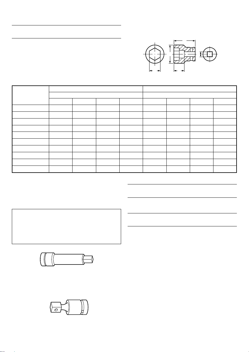
表1 B=19毫米
普通套筒 长形套筒
套筒设计
六角形套筒 22
23
24
26
27
29
30
32
35
36
S
22
23
24
26
27
29
30
32
35
36
尺寸(毫米) 尺寸(毫米)
32
38
40
42
43
45
47
50
52
55
D
32
29
29
29
29
29
29
29
29
29
E
L
60
55
55
55
55
55
55
55
55
55
S
23
24
26
27
29
30
32
35
36
D
33
34
38
39
42
43
46
52
55
32
32
57
57
57
57
72
72
72
E
L
60
60
85
85
85
85
85
100
100
100
2. 延长杆
工作空间有限时,或所备的套筒难于碰到所要旋
紧的螺母时,使用延长杆是极其方便的。
注意∶
使用延长杆时,与普通转矩相比,旋紧转矩会稍
微变小。因此,要想获得同样的转矩,需操作较
长的时间。
3. 万向接头
套筒和扳手之间有一角度时,或操作空间非常小
时,使用万向接头来冲击螺母是极其方便的。
选购附件可能不预先通告而予以更改。
用 途
嘷 各种螺栓、螺母的旋紧或旋松。
作 业 之 前
1. 电源
确认所使用的电源与工具铭牌上标示的规格是否
相符。
2. 电源开关
确认电源开关是否切断。若电源开关接通,则插
头插入电源插座时电动工具将出其不意地立刻转
动,从而招致严重事故。
3. 延伸线缆
若作业场所移到离开电源的地点,应使用容量足
够、装合适的延伸线缆,并且要尽可能地短些。
4. 边柄的固定
装配在锤盒上的边柄位置可通过旋松边柄来改变
(右侧的螺丝)。工作时,请将边柄旋转至所要
的位置,并拧紧。
5
Page 7

5. 选择合适的套筒
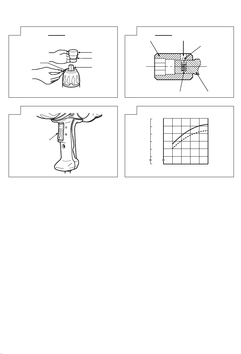
(1) 插销、O型套环 (图 1)
请选择一个大小与需要旋紧或者旋松的螺栓相配
的套筒。将其插进扳手的铁砧后,再用插销和套
环将其固定住。拆卸套筒时,请按照与上述相反
顺序进行操作。
(2) 活塞式(图 2)
将位于铁砧正方形部位上的活塞与六角插槽上的
孔对准。然后压下活塞,将六角插槽安装在铁砧
上。检查活塞和孔是否彻底结合。当拆卸插槽
时,按相反顺序操作。
使 用 方 法
1. 开关的操作(图 3)
此工具上的开关具有开关马达及转换马达旋转方
向的功能。将开关设于标志在把手上的“R”位置
时,马达朝着顺时针方向旋转而旋紧螺栓。将开
关设于“L”位置时,马达朝着逆时针方向旋转而
旋松螺栓。而松开开关时,马达便停止旋转。
注意∶
改变扳手的旋转方向之前,请关掉开关并等到马
达完全停止。如在马达旋转时进行开关操作的
话,将就会烧毁马达。
2. 旋紧或旋松螺栓
请事先选择一个与螺栓或螺母配套的六角套筒,
然后将此套筒装配在铁砧上,并用六角套筒扣住
所要旋转的螺母。将扳手对准螺栓,然后按下电
源开关冲击螺母数秒钟。如果螺母一直不能被紧
固地固定在螺栓上,则说明螺栓跟着螺母一起在
转。这时,请停止冲击,用另一个扳手固定住螺
栓头部然后再重新冲击或用手旋紧螺栓和螺母以
防它们滑动。
操作时的注意事项
1. 确保线电压(图 4)
有效旋紧转矩会受到线电压的影响。电压的减少
会降低有效旋紧转矩。
例如:如果您在200伏电压环境下使用220伏型扳
手时,转矩会降低至70%到90%。需要使用电源延
长线时,应尽量使用短的延长线。当线电压较低
同时又要使用长的电源延长线时,请使用升压变
压器。线电压与旋紧转矩之间的关系如各图所
示。
2. 在连续操作时不要接触减震器和电动锤
在连续旋转上紧过程中减震器和电动锤会变热,
所以在这过程中务必要小心不要接触它们。
3. 使用最佳旋紧转矩
最适合螺母和螺栓的旋紧转矩因螺母和螺栓的材
料、尺寸而导。对小的螺栓施加过大的旋紧转矩
会导致螺栓的变形或断裂。旋紧转距随着操作时
间的增加而增大,请正确掌握对螺栓的操作时
间。
4. 选择与螺栓相配的套筒
注意要选择使用与螺栓相配的套筒,使用不相配
的套筒时,不仅会影响旋紧力,还会使套筒或螺
母受损。
如使用已损坏了的、或已变形的六角或四角套
筒,由于无法得到适当的旋紧力,因而会导致旋
紧转矩的损失。
请注意套筒内部的磨损,并请在磨损程度加重之
前更换之。和螺栓尺寸配套的套筒示于表1。
套筒牌号处的数值表示六角型孔的一边到另外一
边的距离(S)。
5. 扳手的拿法
请用双手紧紧地握住冲击扳手的主柄和边柄。并
将扳手对准螺栓。
没有必要对扳手施加太大的力,只需施加可抵消
冲击力的力即可。
6. 确保施紧转矩
以下各个因素与旋紧转矩相关。为了确保旋紧转
矩,必须在开始操作之前先用普通的扳手把螺栓
旋紧。
与旋紧转矩相关的因素如下:
(1) 线电压
旋紧转矩会随着线电压的降低而减小。
(请参考 图 4)
(2) 操作时间
旋紧转矩会随着操作时间的增加而增大。但是,
旋紧转矩达到临界值后,即使操作时间再长旋紧
转矩也不再增大。(请参考 图 4)
6
Page 8

(3) 螺栓的直径
旋紧转矩会因螺母的直径而导(请参考 图 4)。
通常,螺母的直径越大,旋紧转矩便也越大。
(4) 旋紧条件
即使螺纹尺寸相同,旋紧转矩也因转矩率、螺栓
的级别、及螺栓长度而异。另外,各螺栓的金属
表面的状况不同也会导致各旋紧转矩相异。
(5) 选购附件的使用
使用延长柄、万向接头、或长的套筒时,旋紧转
矩会相对减少。
(6) 套筒的障碍排除
如使用已损坏了的、或已变形的六角或四角套
筒,由于无法得到适当的旋紧力,因而会导致旋
紧转矩的损失。
使用和螺栓不相配的套筒时,将不能获得足够得
旋紧转矩。和螺栓尺寸配套的套筒示于表1。
维 护 和 检 查
1. 套筒的检查
如使用已损坏了的、或已变形的六角或四角套
筒,由于无法得到适当的旋紧力,因而会导致旋
紧转矩的损失。请对套筒内部的磨损程度紧行周
期检查,必要时请换上新的套筒。
2. 检查安装螺钉
要经常检查安装螺钉是否紧固妥善。若发现螺钉
松了,应立即重新扭紧,否则会导致严重的事
故。
3. 电动机的维护
电动机绕线是电动工具的“心脏部”应仔细检查
有无损伤,是否被油液或水沾湿。
4. 检查碳刷
为了保证长期的安全使用以及避免触电事故的发
生,本工具的碳刷检查与更换只能由日立授权的
服务中心进行。
5. 维修零部件一览表
A:项目号
B:代码号
C:使用数
D:备注
注意∶
日立牌电动工具的维修、改造和检查须由经日立公
司授权的维修中心进行。
当要求维修或其他保养服务时,若将此零部件一览
表与电动工具一起呈交给经日立公司授权的维修中
心,将有助于维修或保养工作。
在操作和维修电动工具时,必须遵守贵国制定的安
全的有关规则和标准。
改造∶
日立牌电动工具经常加以改善和改造以采用最新的
先进技术。
因此,某些零部件〔例如代码号和(或)设计〕可
能变更,恕不另行通知。
注∶
为求改进,本手册所载规格可能不预先通告而予以
更改。
7
Page 9

English
GENERAL SAFETY RULES
WARNING!
Read all instructions
Failure to follow all instructions listed below may result in
electric shock, fire and/or serious injury.
The term “power tool” in all of the warnings listed below
refers to your mains operated (corded) power tool or battery
operated (cordless) power tool.
SAVE THESE INSTRUCTIONS
1) Work area
a) Keep work area clean and well lit.
Cluttered and dark areas invite accidents.
b) Do not operate power tools in explosive
atmospheres, such as in the presence of flammable
liquids, gases or dust.
Power tools create sparks which may ignite the
dust of fumes.
c) Keep children and bystanders away while operating
a power tool.
Distractions can cause you to lose control.
2) Electrical safety
a) Power tool plugs must match the outlet.
Never modify the plug in any way.
Do not use any adapter plugs with earthed
(grounded) power tools.
Unmodified plugs and matching outlets will reduce
risk of electric shock.
b) Avoid body contact with earthed or grounded
surfaces such as pipes, radiators, ranges and
refrigerators.
There is an increased risk of electric shock if your
body is earthed or grounded.
c) Do not expose power tools to rain or wet
conditions.
Water entering a power tool will increase the risk
of electric shock.
d) Do not abuse the cord. Never use the cord for
carrying, pulling or unplugging the power tool.
Keep cord away from heat, oil, sharp edges or
moving parts.
Damaged or entangled cords increase the risk of
electric shock.
e) When operating a power tool outdoors, use an
extension cord suitable for outdoor use.
Use of a cord suitable for outdoor use reduces
the risk of electric shock
3) Personal safety
a) Stay alert, watch what you are doing and use
common sense when operating a power tool.
Do not use a power tool while you are tired or
under the influence of drugs, alcohol or medication.
A moment of inattention while operating power
tools may result in serious personal injury.
b) Use safety equipment. Always wear eye protection.
Safety equipment such as dust mask, non-skid
safety shoes, hard hat, or hearing protection used
for appropriate conditions will reduce personal
injuries.
c) Avoid accidental starting. Ensure the switch is in
the off position before plugging in.
Carrying power tools with your finger on the
switch or plugging in power tools that have the
switch on invites accidents.
8
d) Remove any adjusting key or wrench before
turning the power tool on.
A wrench or a key left attached to a rotating part
of the power tool may result in personal injury.
e) Do not overreach. Keep proper footing and balance
at all times.
This enables better control of the power tool in
unexpected situations.
f) Dress properly. Do not wear loose clothing or
jewellery. Keep your hair, clothing and gloves
away from moving parts.
Loose clothes, jewellery or long hair can be caught
in moving parts.
g) If devices are provided for the connection of dust
extraction and collection facilities, ensure these
are connected and properly used.
Use of these devices can reduce dust related hazards.
4) Power tool use and care
a) Do not force the power tool. Use the correct
power tool for your application.
The correct power tool will do the job better and
safer at the rate for which it was designed.
b) Do not use the power tool if the switch does not
turn it on and off.
Any power tool that cannot be controlled with the
switch is dangerous and must be repaired.
c) Disconnect the plug from the power source before
making any adjustments, changing accessories, or
storing power tools.
Such preventive safety measures reduce the risk
of starting the power tool accidentally.
d) Store idle power tools out of the reach of children
and do not allow persons unfamiliar with the
power tool or these instructions to operate the
power tool.
Power tools are dangerous in the hands of
untrained users.
e) Maintain power tools. Check for misalignment or
binding of moving parts, breakage of parts and
any other condition that may affect the power
tools operation.
If damaged, have the power tool repaired before
use.
Many accidents are caused by poorly maintained
power tools.
f) Keep cutting tools sharp and clean.
Properly maintained cutting tools with sharp cutting
edges are less likely to bind and are easier to
control.
g) Use the power tool, accessories and tool bits etc.,
in accordance with these instructions and in the
manner intended for the particular type of power
tool, taking into account the working conditions
and the work to be performed.
Use of the power tool for operations different from
intended could result in a hazardous situation.
5) Service
a) Have your power tool serviced by a qualified repair
person using only identical replacement parts.
This will ensure that the safety of the power tool
is maintained.
PRECAUTION
Keep children and infirm persons away.
When not in use, tools should be stored out of reach of
children and infirm persons.
Page 10

English
S
D
B
E
L
PRECAUTIONS ON USING IMPACT WRENCH
1. When using the tool at a hight, make sure that there
is nobody below.
2. Use earplugs if using for a long time use.
3. Switch the reversing switch only after the motor
has stoped when it is necessary to change the
direction of the rotation.
4. Use a step up transformer when a long extension
cable is used.
5. Confirm the tightening torque by a torque wrench
before use in order to assertain the correct tightening
torque to be used.
6. Assemble the socket securely to the impact wrench
with the socket pin and ring.
7. Confirm whether the socket has any cracks in it.
8. Always hold the body and side handles of the
impact wrench firmly. Otherwise the counterforce
produced may result in inaccurate and even
dangerous operation.
SPECIFICATIONS
Voltage (by areas)* (110V, 115V, 120V, 127V, 220V, 230V, 240V)
Power input* 800 W
No load speed 1800 / min
Capacities (size of bolts)
Tightening torque** Maximum 610N·m (62.2 kg-m)
Angle drive 19 mm
Weight (without cord) 4.8 kg
*Be sure to check the nameplate on product as it is subject to change by areas.
**Tightening the bolt without extension cord at rated voltage.
STANDARD ACCESSORIES
(1) Side handle ............................................................... 1
(2) Case ........................................................................... 1
Standard accessories are subject to change without notice.
M16 - M22 (High tension bolt)
M14 - M24 (Ordinary bolt)
OPTIONAL ACCESSORIES
(sold separately)
1. Variety of sockets
Although the Hitachi Impact Wrench is delivered
with only one standard socket, ample sockets are
available to cover impact tightening of various sizes
and types of bolts.
Table 1 B = 19 mm
Socket
Designation
Hex. Socket 22
S
22
23
24
26
27
29
30
32
35
36
23
24
26
27
29
30
32
35
36
Ordinary Socket Long Socket
Dimension (mm) Dimension (mm)
D
32
38
40
42
43
45
47
50
52
55
E
32
29
29
29
29
29
29
29
29
29
L
60
55
55
55
55
55
55
55
55
55
S
23
24
26
27
29
30
32
35
36
D
33
34
38
39
42
43
46
52
55
E
32
32
57
57
57
57
72
72
72
L
60
60
85
85
85
85
100
100
100
9
Page 11

English
2. Extension bar
The extension bar is convenient for working in very
restricted spaces or when the socket provided cannot
reach the bolt to be tightened.
CAUTION
When the extension bar is used the tightening torque
is reduced slightly compared with the ordinary
socket. So it is necessary to operate the tool a little
longer to get the same torque.
3. Universal joint
The universal joint is convenient for impacting nuts
when there is an angle between the socket and
wrench, or when working in a very narrow space.
Optional accessories are subject to change without notice.
APPLICATIONS
䡬 Tightening and loosening various kinds of bolt and
nut.
PRIOR TO OPERATION
1. Power source
Ensure that the power source to be utilized conforms
to the power requirements specified on the product
nameplate.
2. Power switch
Ensure that the power switch is in the OFF position.
If the plug is connected to a receptacle while the
power switch is in the ON position, the power tool
will start operating immediately, which could cause
a serious accident.
3. Extension cord
When the work area is removed from the power
source, use an extension cord of sufficient thickness
an rated capacity. The extension cord should be
kept as short as practicable.
4. Fixing the side handle
The position of the side handle attached to the
hammer case can be changed by unscrewing the
handle. (Right hand screw) Turn the handle to the
desired position for the job and secure the handle
by screwing up tight.
5. Mounting the socket
(1) Pin, O-ring type (Fig. 1)
Select a socket matched to the bolt to be tightened
or loosened. Insert the socket on the anvil of the
wrench, and secure it with the pin and ring. When
dismantling the socket, reverse the sequence.
(2) Plunger type (Fig. 2)
Align the plunger located in the square part of the
anvil with the hole in the hex socket. Then push
the plunger, and mount the hex socket on the anvil.
Check that the plunger is fully engaged in the hole.
When removing the socket, reverse the sequence.
HOW TO USE
1. Operation of switch (Fig. 3)
The switch in this machine functions as a motor
switch and rotational direction selector switch. When
the switch is set to R indicated on the handle cover,
the motor rotates clockwise to tighten the bolt.
When the switch is set to L, the motor rotates
counterclockwise to loosen the bolt. When the switch
is released, the motor stops.
CAUTION
Be sure to turn the switch OFF and wait until the
motor completely stops before changing the
direction of wrench revolution. Switching while the
motor is rotating will result in burning the motor.
2. Tightening and loosening bolts
A hex socket matching the bolt or nut must first
be selected. Then mount the socket on the anvil,
and grip the nut to be tightened with the hex socket.
Holding the wrench in line with the bolt, press the
power switch to impact the nut for several seconds.
If the nut is only loosely fitted to the bolt, the bolt
may turn with the nut, therefore preventing proper
tightening. In this case, stop impact on the nut and
hold the bolt head with a wrench before restarting
impact, or manually tighten the bolt and nut to
prevent them slipping.
OPERATIONAL CAUTIONS
1. Confirm the line voltage (Fig. 4)
The available tightening torque is influenced by line
voltage. Reduced line voltage lowers the available
tightening torque.
For example, if you use a 220 V type wrench on
a 200 V line the available tightening torque will be
reduced to 70 to 90 %. When extending the power
cord, use an extension cord which is as short as
possible. When the line voltage is low and a long
extension cord is needed a step up transfomer
should be used. The relation between the line voltage
and the tightening torque are shown in the figures.
2. Do not touch the bumper or hammer case during
continuous operation
The bumper and hammer case become hot during
continuous screw tightening so be careful not to
touch them at that time.
3. Work at a tightening torque suitable for the bolt
under impact
The optimum tightening torque for nuts and bolts
differs with material and size of the nuts and bolts.
An excessively large tightening torque for a small
bolt may strech or break the bolt. The tightening
torque increases proportionally to the operating
time. Use the correct operating time for the bolt.
4. Selecting the socket to be matched to the bolt
Be sure to use a socket which is matched to the
bolt to be tightened. Using an improper socket will
result not only in insufficient tightening but also in
damage to the socket or nut.
A worn or deformed hex or square-holed socket will
not give an adequate tightness for fitting to the nut
or anvil, consequently resulting in loss of tightening
torque.
Pay attention to wear of socket holes, and replace
10
Page 12

English
before further wear developes. Matching socket and
bolt sizes are shown in Table 1.
The numerical value of a socket designation denotes
the side to side distance (S) of its hex hole.
5. Holding the tool
Hold the Impact Wrench firmly with both hands by
the body handle and the side handle. In this case
hold the wrench in line with the bolt.
It is not necessary to push the wrench very hard.
Hold the wrench with a force just sufficient to
counteract the impact force.
6. Confirm the tightening torque
The following factors contribute to a reduction of
the tightening torque. So confirm the actual
tightening torque needed by screwing up some
bolts before the job with a hand torque wrench.
Factors affecting the tightening torque are as follows.
(1) Line voltage:
The tightening torque decreases when the line
voltage becomes low (See Fig. 4).
(2) Operating time:
The tightening torque increases when the operating
time increases. But the tightening torque does not
increase above a certain value even if the tool is
driven for a long time (See Fig. 4).
(3) Diameter of bolt:
The tightening torque differs with the diameter of
the bolt as shown in Fig. 4. Generally a larger
diameter bolt has a larger tightening torque.
(4) Tightening conditions:
The tightening torque differs according to the torque
ratio; class, and length of bolts even when bolts
with the same size threads are used. The tightening
torque also differs according to the condition of the
surface of metal through which the bolts are to be
tightened.
(5) Using optional parts:
The tightening torque is reduced a little when an
extension bar, universal joint or a long socket is
used.
(6) Clearance of the socket:
A worn or deformed hex or a square-holed socket
will not give an adequate tightness to the fitting
between the nut or anvil, consequently resulting in
loss of tightening torque.
Using an improper socket which does not match
to the bolt will result in an insufficient tightening
torque. Matching socket and bolt sizes are shown
in Table 1.
3. Maintenance of the motor
The motor unit winding is the very “heart” of the
power tool.
Exercise due care to ensure the winding does not
become damaged and/or wet with oil or water.
4. Inspecting the carbon brushes
For your continued safety and electrical shock
protection, carbon brush inspection and replacement
on this tool should ONLY be performed by a Hitachi
Authorized Service Center.
5. Replacing supply cord
If the supply cord of Tool is damaged, the Tool
must be returned to Hitachi Authorized Service
Center for the cord to be replaced.
6. Service parts list
A: Item No.
B: Code No.
C: No. Used
D: Remarks
CAUTION
Repair, modification and inspection of Hitachi Power
Tools must be carried out by a Hitachi Authorized
Service Center.
This Parts List will be helpful if presented with the
tool to the Hitachi Authorized Service Center when
requesting repair or other maintenance.
In the operation and maintenance of power tools,
the safety regulations and standards prescribed in
each country must be observed.
MODIFICATION
Hitachi Power Tools are constantly being improved
and modified to incorporate the latest technological
advancements.
Accordingly, some parts (i.e. code numbers and/or
design) may be changed without prior notice.
NOTE
Due to HITACHI’s continuing program of research and
development, the specifications herein are subject to
change without prior notice.
MAINTENANCE AND INSPECTION
1. Inspecting the socket
A worn or deformed hex or a square-holed socket
will not give an adequate tightness to the fitting
between the nut or anvil, consequently resulting in
loss of tightening torque. Pay attention to wear of
socket holes periodically, and replace with a new
one if needed.
2. Inspecting the mounting screws
Regularly inspect all mounting screws and ensure
that they are properly tightened. Should any of the
screws be loose, retighten them immediately. Failure
to do so could result in serious hazard.
11
Page 13

39 930-153 1
40 316-186 1
ABC D
1 324-008 1
2 323-994 4 M5×45
ABC D
41 958-308Z 1
42 324-023 1
43 961-419Z 1
44 608-VVM 1 608VVC2PS2L
45 ————1
3 324-006 1 “1, 2, 4, 5”
4 971-028 1 P-28
5 324-007 1
6-1 324-013 1
6-2 324-021 1 “13-15”
46 323-997 1
47 877-839 2 M5×10
7 959-151 2 D7.14
8 324-005 1
48 984-750 2 D4×16
49 937-631 1
9 959-155 38 D3.97
10 324-004 1
51 ————1
50-1 953-327 1 D8.8
50-2 938-051 1 D10.1
11 324-002 1
12 324-001 1
13 949-507 1 D2×14 “AUS”
52 ————1
53 935-829 2
54 999-043 2
14 992-571 1 “AUS”
15 992-572 1 “AUS”
16 971-016 2
55 957-774 2
56 324-019 1 “55, 57”
17 324-003 1
18 318-448 2
57 938-477 2 M5×8
501 324-015 1 “502-505”
502 980-901 1
503 323-775 1
19 991-449 1
20 985-303 1
21 690-8ZZ 1 6908ZZC2PS2L
22 323-995 1
504 324-016 1
505 980-903 1 M8
506 324-014 1
23 323-999 1
24 323-996 1
25 971-012 1
26 620-0DD 1 6200DDCMPS2L
27-1 360-700C 1 110V
27-2 360-700E 1 220V-230V
27-3 360-700F 1 240V
28 323-998 1
29 961-400 2 D5×70
30-1 324-017 1
30-2 324-009 1 “VEN, INA, SYR,
KUW, HKG, SIN”
KUW, HKG, SIN”
31-1 324-018 1
31-2 324-010 1 “VEN, INA, SYR,
32-1 340-620C 1 110V
32-2 340-620E 1 220V-230V
32-3 340-620F 1 240V
33 960-354 2
34 303-694 1 D4×35
35 324-020 1
36 320-528 1
37 323-768 1
38 323-780 1
12
Page 14

13
Page 15

14
Page 16

15
Page 17

Hitachi Koki Co., Ltd.
412
Code No. C99137621 N
Printed in Japan
 Loading...