

Page 1

HUAWEI TE80 Videoconferencing Endpoint
V100R001C01
Administrator Guide
Issue
02
Date
2014-01-15
HUAWEI TECHNOLOGIES CO., LTD.
Page 2

Issue 02 (2014-03-30)
Huawei Proprietary and Confidential
Copyright © Huawei Technologies Co., Ltd.
i
Copyright © Huawei Technologies Co., Ltd. 2014. All rights reserved.
No part of this document may be reproduced or transmitted in any form or by any means without prior
written consent of Huawei Technologies Co., Ltd.
Trademarks and Permissions
and other Huawei trademarks are trademarks of Huawei Technologies Co., Ltd.
All other trademarks and trade names mentioned in this document are the property of their respective
holders.
Notice
The purchased products, services and features are stipulated by the contract made between Huawei and
the customer. All or part of the products, services and features described in this document may not be
within the purchase scope or the usage scope. Unless otherwise specified in the contract, all statements,
information, and recommendations in this document are provided "AS IS" without warranties, guarantees or
representations of any kind, either express or implied.
The information in this document is subject to change without notice. Every effort has been made in the
preparation of this document to ensure accuracy of the contents, but all statements, information, and
recommendations in this document do not constitute a warranty of any kind, express or implied.
Huawei Technologies Co., Ltd.
Address:
Huawei Industrial Base
Bantian, Longgang
Shenzhen 518129
People's Republic of China
Website:
http://enterprise.huawei.com
Page 3
HUAWEI TE80 Videoconferencing Endpoint
Administrator Guide
About This Document
Issue 02 (2014-03-30)
Huawei Proprietary and Confidential
Copyright © Huawei Technologies Co., Ltd.
ii
Before you use the product, refer to the product vendor for version mapping information and
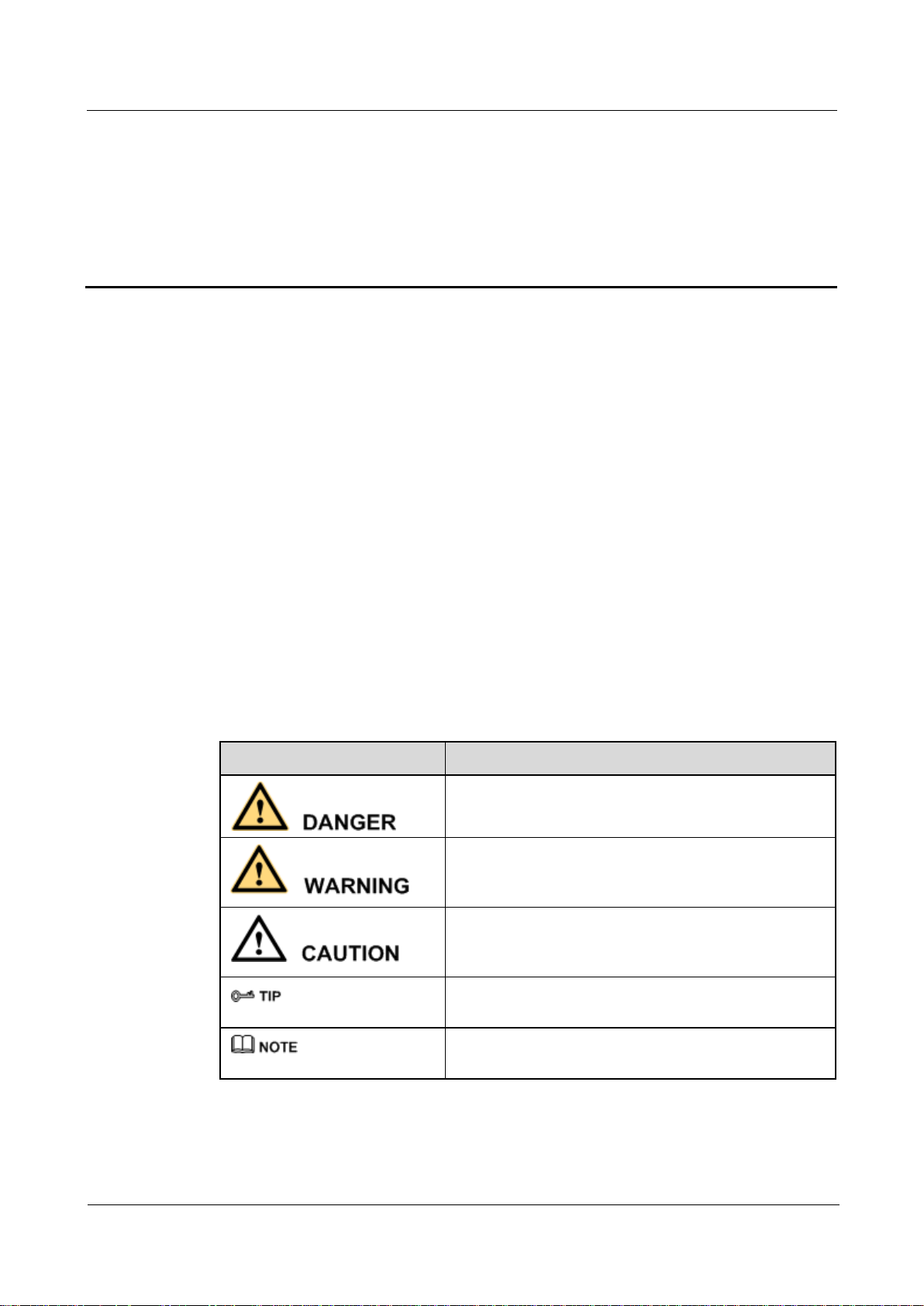
Symbol
Description
Indicates a hazard with a high level of risk, which if not
avoided, will result in death or serious injury.
Indicates a hazard with a medium or low level of risk,
which if not avoided, could result in minor or moderate
injury.
Indicates a potentially hazardous situation, which if not
avoided, could result in equipment damage, data loss,
performance degradation, or unexpected results.
Indicates a tip that may help you solve a problem or save
time.
Provides additional information to emphasize or
supplement important points of the main text.
to confirm compatibility with other videoconferencing equipment.
This document describes how to install, configure, maintain, and troubleshoot the HUAWEI
HUAWEI TE80 Videoconferencing Endpoint (TE80 or endpoint for short). It also provides
step-by-step instructions on conferencing tasks.
Intended Audience
This document is intended for but not limited to endpoint administrators.
About This Document
An endpoint administrator has access to all functions on the endpoint web interface and
remote controlled user interface (UI).
Symbol Conventions
The symbols that may be found in this document are defined as follows.
Page 4

HUAWEI TE80 Videoconferencing Endpoint
Administrator Guide
About This Document
Issue 02 (2014-03-30)
Huawei Proprietary and Confidential
Copyright © Huawei Technologies Co., Ltd.
iii
Change History
Changes between document issues are cumulative. The latest document issue contains all the
changes made in earlier issues.
Issue 02 (2014-01-15)
This issue is the second official release, which incorporates the following changes:
Modified section 3.1.2 "Setting IP Parameters."
Modified section 3.1.3 "Setting H.323 Parameters."
Modified section 3.1.5 "Setting Wi-Fi Parameters."
Modified section 4.2.1 "Configuring Video Output."
Modified section 4.2.4 "Setting Video Parameters."
Modified section 4.2.5 "Switching Between Screen Layouts."
Modified section 4.6 "Setting Camera Presets."
Modified section 5.1.3 "Setting Audio Parameters."
Modified section 5.4 "Adjusting Audio Effects."
Modified section 6.1 "Designating the Dual Streams."
Modified section 7.1 "Setting the Administrator Password."
Modified section 8.1 "Customizing the Home Screen."
Modified section 8.4 "Customizing the Option Bar."
Modified section 9.2 "Logging In to the Endpoint Web Interface."
Modified section 9.3.3 "Downloading an Air Content Sharing Client."
Added section 13.7 "Setting Network Diagnostics Parameters."
Issue 01 (2013-09-30)
This issue is the first official release.
Page 5

HUAWEI TE80 Videoconferencing Endpoint
Administrator Guide
Contents
Issue 02 (2014-03-30)
Huawei Proprietary and Confidential
Copyright © Huawei Technologies Co., Ltd.
iv
Contents
About This Document .................................................................................................................... ii
1 Overview ......................................................................................................................................... 1
1.1 Definition of an Endpoint Administrator ...................................................................................................................... 2
1.2 Requirements for an Endpoint Administrator ................................................................ ................................ ............... 2
1.3 Related Documentation............................................................................................................... 错误!未定义书签。
1.4 Safety Precautions ........................................................................................................................................................ 3
1.5 How to Obtain Help ...................................................................................................................................................... 9
2 Basic Configuration and Verification ..................................................................................... 10
2.1 Powering On or Off the Endpoint ............................................................................................................................... 10
2.2 Using the Wizard ........................................................................................................................................................ 12
2.3 Verifying the Basic Configuration .............................................................................................................................. 13
2.3.1 Call Test ................................................................................................................................................................... 13
2.3.2 Sound Test ............................................................................................................................................................... 14
2.3.3 Image Test ................................................................................................................................................................ 14
2.4 Power Management .................................................................................................................................................... 15
3 Network ........................................................................................................................................ 18
3.1 Connecting to an IP LAN Network ............................................................................................................................. 18
3.1.1 Checking Status Indicators of the LAN Port ........................................................................................................... 18
3.1.2 Setting IP Parameters ............................................................................................................................................... 19
3.1.3 Setting H.323 Parameters ........................................................................................................................................ 22
3.1.4 Setting SIP Parameters ............................................................................................................................................. 24
3.1.5 Setting Wi-Fi Parameters ......................................................................................................................................... 27
3.2 Connecting to a 4E1 Network ..................................................................................................................................... 31
3.2.1 Inserting a 4E1 Interface Card ................................................................................................................................. 31
3.2.2 Checking Status Indicators on the 4E1 Ports ........................................................................................................... 33
3.2.3 Setting 4E1 Parameters ............................................................................................................................................ 33
4 Display Device and Camera ...................................................................................................... 35
4.1 Connecting a Display Device ..................................................................................................................................... 35
4.2 Configuring a Display Device .................................................................................................................................... 39
4.2.1 Configuring Video Output ....................................................................................................................................... 39
4.2.2 Adjusting the Picture Offset ..................................................................................................................................... 44
Page 6

HUAWEI TE80 Videoconferencing Endpoint
Administrator Guide
Contents
Issue 02 (2014-03-30)
Huawei Proprietary and Confidential
Copyright © Huawei Technologies Co., Ltd.
v
4.2.3 Adjusting the Sampling Phase ................................................................................................................................. 44
4.2.4 Setting Video Parameters ......................................................................................................................................... 45
4.2.5 Switching Between Screen Layouts ......................................................................................................................... 47
4.3 Connecting a Camera ................................ ................................ ................................ .................................................. 48
4.4 Configuring Video Input ............................................................................................................................................. 49
4.5 Selecting and Controlling a Camera ........................................................................................................................... 51
4.6 Setting Camera Presets ............................................................................................................................................... 52
5 Microphone and Speaker .......................................................................................................... 54
5.1 Connecting an Audio Input Device ............................................................................................................................. 54
5.1.1 Connecting a VPM220 ............................................................................................................................................. 55
5.1.2 Connecting a VPM220W ......................................................................................................................................... 57
5.1.3 Setting Audio Parameters ......................................................................................................................................... 59
5.2 Connecting an Audio Output Device .......................................................................................................................... 62
5.2.1 Connecting a Speaker .............................................................................................................................................. 62
5.2.2 Placing an External Speaker .................................................................................................................................... 62
5.2.3 Adjusting the Speaker Volume ................................................................................................................................. 62
5.3 Connecting a Tuning Console ..................................................................................................................................... 62
5.4 Adjusting Audio Effects .............................................................................................................................................. 62
5.5 Enjoying Stereo Audio ................................................................................................................................................ 64
6 Conference .................................................................................................................................... 65
6.1 Experiencing a Dual-Stream Conference .................................................................................................................... 66
6.1.1 Designating the Dual Streams ................................................................................................................................ .. 66
6.1.2 Sharing a Presentation ............................................................................................................................................. 67
6.1.3 Viewing the Combined Picture of the Presentation and the Video .......................................................................... 67
6.2 Experiencing an MSUC Conference ........................................................................................................................... 68
6.3 Joining an Authentication Conference ........................................................................................................................ 70
6.4 Joining an HD-Video Conference over an IMS Network ........................................................................................... 72
6.5 Scheduling a Conference ............................................................................................................................................ 75
6.6 Controlling a Conference ............................................................................................................................................ 75
6.6.1 Conference Control for a Non-Chair Site ................................................................................................................ 76
6.6.2 Conference Control for the Chair Site ..................................................................................................................... 77
6.7 Recording a Conference.............................................................................................................................................. 80
6.8 Managing the Address Book ....................................................................................................................................... 81
6.8.1 Configuring the Network Address Book .................................................................................................................. 81
6.8.2 Managing the Local Address Book .......................................................................................................................... 84
6.8.3 Importing and Exporting an Address Book .............................................................................................................. 86
6.8.4 Customizing a Site Template ................................................................................................................................... 87
6.9 Managing Captions ..................................................................................................................................................... 89
6.9.1 Specifying Caption Settings ..................................................................................................................................... 89
6.9.2 Creating a Banner or Caption .................................................................................................................................. 91
7 Security.......................................................................................................................................... 92
Page 7

HUAWEI TE80 Videoconferencing Endpoint
Administrator Guide
Contents
Issue 02 (2014-03-30)
Huawei Proprietary and Confidential
Copyright © Huawei Technologies Co., Ltd.
vi
7.1 Setting the Administrator Password ............................................................................................................................ 92
7.2 Enabling Encryption ................................................................................................................................................... 93
7.3 Supporting Remote Logins ......................................................................................................................................... 94
7.4 Setting the Upgrade Password .................................................................................................................................... 96
7.5 Setting the Air Content Sharing Password .................................................................................................................. 96
8 Screen Customization................................................................................................................. 98
8.1 Customizing the Home Screen.................................................................................................................................... 98
8.2 Customizing Onscreen Status Icons.......................................................................................................................... 100
8.3 Customizing Conference Control Functions to Be Displayed .................................................................................. 100
8.4 Customizing the Option Bar ..................................................................................................................................... 101
9 Embedded Web Management Interface ............................................................................... 102
9.1 Web Browser ............................................................................................................................................................. 103
9.2 Logging In to the Endpoint Web Interface ................................................................................................................ 104
9.3 Getting to Know Web Interface Functions ................................................................................................................ 105
9.3.1 Importing and Exporting Settings .......................................................................................................................... 105
9.3.2 Importing License Files ......................................................................................................................................... 106
9.3.3 Downloading an Air Content Sharing Client ......................................................................................................... 106
9.3.4 Multi-View ............................................................................................................................................................. 108
9.3.5 Customizing Shortcut Bar and Desktop Icons ....................................................................................................... 109
9.3.6 Accessing the Site Map .......................................................................................................................................... 109
9.3.7 Importing a Certificate ........................................................................................................................................... 109
9.3.8 Monitoring the Video ............................................................................................................................................. 110
9.3.9 Using the Virtual Remote Control ......................................................................................................................... 110
10 Maintenance ............................................................................................................................. 111
10.1 Checking the Working Environment Periodically .................................................................................................. 111
10.2 Checking the Endpoint Periodically ....................................................................................................................... 112
10.3 Viewing System Status ........................................................................................................................................... 112
10.4 Querying System Information ................................................................................................................................ 113
10.5 Querying Logs ........................................................................................................................................................ 113
11 Upgrading ................................................................................................................................. 115
11.1 Automatic Upgrade ................................................................................................................................................. 116
11.2 Tool Upgrade .......................................................................................................................................................... 117
11.3 Upgrading the Endpoint Using the Bootrom System .............................................................................................. 120
11.4 Upgrading the Endpoint on Its Web Interface ......................................................................................................... 121
12 Troubleshooting ...................................................................................................................... 122
12.1 Fault Diagnostics .................................................................................................................................................... 122
12.2 Troubleshooting ...................................................................................................................................................... 125
12.3 Restoring Default Settings ................................................................................................ ................................ ...... 135
13 Feature Configuration ............................................................................................................ 136
Page 8

HUAWEI TE80 Videoconferencing Endpoint
Administrator Guide
Contents
Issue 02 (2014-03-30)
Huawei Proprietary and Confidential
Copyright © Huawei Technologies Co., Ltd.
vii
13.1 Setting the Number Keys and Power Key on the Remote Control ......................................................................... 137
13.2 Setting the Parameters for Placing and Answering Calls ........................................................................................ 137
13.3 Setting Advanced Conference Parameters .............................................................................................................. 139
13.4 Setting SNMP Parameters ....................................................................................................................................... 143
13.5 Setting QoS Parameters .......................................................................................................................................... 145
13.6 Setting Network Diagnostics Parameters ................................................................................................................ 147
13.7 Setting Network Diagnostics Parameters ................................................................................................................ 148
14 Ports on the Rear Panel .......................................................................................................... 151
A E1 and T1 Grounding Criteria ............................................................................................... 152
B Technical Specifications ......................................................................................................... 153
C Status Icons ................................................................................................................................ 157
D Menus ......................................................................................................................................... 160
E Terminology .............................................................................................................................. 162
F Acronyms and Abbreviations ................................................................................................. 168
Page 9

HUAWEI TE80 Videoconferencing Endpoint
Administrator Guide
1 Overview
Issue 02 (2014-03-30)
Huawei Proprietary and Confidential
Copyright © Huawei Technologies Co., Ltd.
1
About This Chapter
This document guides you through configuring, managing, maintaining, and troubleshooting
the endpoint.
When using this document, note the following:
Unless otherwise specified, the descriptions in this document are applicable to the TE80.
Except chapters 9 Embedded Web Management Interface, 10 Maintenance, 12
Troubleshooting and 13.4 Setting SNMP Parameters which apply to the endpoint web
interface, descriptions and configurations in this document apply to the endpoint user
interface controlled by the remote control (remote controlled UI for short).
1 Overview
To access the menu screen, press on the remote control. You can find the option
bar on the left of the menu screen. This option bar is configurable and is your interface
for all functions except calling. For details about how to configure the option bar, see 8.4
Customizing the Option Bar.
To prevent endpoint parameters from being modified by unauthorized users, anyone who
wants to access the Settings screen and use the customized tool bar on the menu
screen must provide the administrator password if the password is not set to blank. For
details about how to set the password, see 7.1 Setting the Administrator Password.
1.1 Definition of an Endpoint Administrator
An endpoint administrator is an enterprise employee who is responsible for managing and
maintaining endpoint operations.
1.2 Requirements for an Endpoint Administrator
As an endpoint administrator, you must meet the following basic endpoint administrator
proficiencies and be capable of collecting all information related to the endpoint and its
working environment.
1.3 Related Documentation
This section lists the documentation that you may refer to when you perform routine
operations and maintenance as well as answering questions from standard users.
1.4 Safety Precautions
Page 10

HUAWEI TE80 Videoconferencing Endpoint
Administrator Guide
1 Overview
Issue 02 (2014-03-30)
Huawei Proprietary and Confidential
Copyright © Huawei Technologies Co., Ltd.
2
For safety purposes, carefully read through these safety precautions and observe them during
Category
No.
Item
Description
Device
information
1
Device location
Record the endpoint location in
as much detail as possible so
the endpoint can be quickly
operation.
1.5 How to Obtain Help
When you encounter an endpoint issue, use the help on the endpoint web interface or contact
technical support personnel.
1.1 Definition of an Endpoint Administrator
An endpoint administrator is an enterprise employee who is responsible for managing and
maintaining endpoint operations.
An endpoint administrator has the following job responsibilities:
Configures and manages the endpoint.
Routinely maintains the endpoint.
Troubleshoots the endpoint failures.
Answers standard users' questions about endpoint use.
1.2 Requirements for an Endpoint Administrator
As an endpoint administrator, you must meet the following basic endpoint administrator
proficiencies and be capable of collecting all information related to the endpoint and its
working environment.
Basic Endpoint Administrator Proficiencies
Windows operating system
Gatekeeper (GK) and Session Initiation Protocol (SIP) servers
Ethernet, TCP/IP, and Client/Server (C/S) model
H.323, SIP, and H.320 protocols
Safe and effective use of electronic devices
Common maintenance tools
Videoconferencing endpoint functions and services
Information About the Endpoint and Its Working Environment
Table 1-1 lists the endpoint and working environment information that must be collected,
which helps you fulfill your job responsibilities and check the preparations for a recovery
from an emergency.
Table 1-1 Information to be collected
Page 11

HUAWEI TE80 Videoconferencing Endpoint
Administrator Guide
1 Overview
Issue 02 (2014-03-30)
Huawei Proprietary and Confidential
Copyright © Huawei Technologies Co., Ltd.
3
Category
No.
Item
Description
located.
2
Networking condition
Record the network topology
and hardware connection
diagram that include every
device.
3
Endpoint information
List the IP address, user name,
and password for the endpoint
so you can quickly log in to the
endpoint in case of an
emergency. If you are not
permitted to record the
password for security reasons,
memorize it.
Software
and tools
4
Software versions and tools
List the software versions
corresponding to the endpoint.
Prepare troubleshooting tools.
Contact
information
5
Purchased parts' service
information
Record the manufacturer
contact information, serial
numbers, and manufacturers'
warranty clauses for purchased
parts.
6
Technical support personnel's
contact information
Maintain a list of technical
support personnel with their
contact information and
responsibilities.
Spare parts
7
Spare parts
List all spare parts (including
the spare parts that Huawei can
provide) and corresponding
procurement methods.
8
Redundant or temporary devices
List all redundant or temporary
devices in the system, such as
standby file servers and
database servers.
1.3 Safety Precautions
For safety purposes, carefully read through these safety precautions and observe them during
operation.
Basic Precautions
Keep the device dry and secure from collision during storage, transportation, and
operation of the device.
Page 12

HUAWEI TE80 Videoconferencing Endpoint
Administrator Guide
1 Overview
Issue 02 (2014-03-30)
Huawei Proprietary and Confidential
Copyright © Huawei Technologies Co., Ltd.
4
Do not attempt to dismantle the device by yourself. In case of any fault, contact the
appointed maintenance center for assistance or repair.
Without prior written consent, no organization or individual is permitted to make any
change to the structure or safety and performance design of the device.
While using the device, observe all applicable laws, directives, and regulations, and
respect the legal rights of others.
Environmental Precautions
Place the device in a well-ventilated place. Do not expose the device to direct sunlight.
Install the device strictly according to the requirements of the manufacturer.
Do not place any object on the top of the device. Reserve a minimum space of 10 cm at
the four sides of the device for heat dissipation.
Do not place the device on or near inflammable materials such as foam.
Keep the device away from heat source or fire, such as a radiator or a candle.
Keep the device away from any household appliances with strong electromagnetic fields,
such as a microwave oven, refrigerator, or mobile phone.
Operating Precautions
Do not allow children to play with the device or accessories. Swallowing the accessories
may be fatal.
Use the accessories such as the power adapter and battery provided or authorized only by
the manufacturer.
Ensure that the device does not get wet. If water gets into the device, disconnect the
power supply immediately and unplug all the cables connected to the device, including
the power cable, telephone cable, video cable, audio cable, network cable, and serial
cable, and then contact the appointed maintenance center.
Before plugging or unplugging any cable, shut down the device and disconnect the
power supply. While plugging or unplugging any cable, ensure that your hands are dry.
Do not step on, pull, or overbend any cable. Otherwise, the cable may be damaged,
leading to malfunction of the device.
Do not use old or damaged cables.
In lightning weather, disconnect the device from the power supply and unplug all the
cables connected to the device.
Keep the power plug clean and dry, to prevent electric shock or other dangers.
If the device is not used for a long time, disconnect the power supply and unplug the
power plug.
If smoke, sound, or smell is emitted from the device, stop using the device immediately,
disconnect the power supply, unplug the power plug and other cables, and remove the
batteries. Then, contact the appointed maintenance center for repair.
Ensure that no object (such as metal shavings) enters the device through the heat
dissipation vent.
Before connecting any other cable, connect the ground cable of the device. Do not
disconnect the ground cable until you have disconnected all the other cables.
Ensure that the three-phase power socket is grounded properly. The neutral line and the
live line cannot be connected inversely.
Page 13

HUAWEI TE80 Videoconferencing Endpoint
Administrator Guide
1 Overview
Issue 02 (2014-03-30)
Huawei Proprietary and Confidential
Copyright © Huawei Technologies Co., Ltd.
5
Do not scratch or abrade the shell of the device. The shed painting may lead to skin
allergy or malfunction of the device. If the shed painting material drops into the host, a
short circuit may occur.
Cleaning Precautions
Before cleaning the device, stop using it, disconnect the power supply, and unplug all the
cables connected to the device, including the power cable, telephone cable, video cable,
audio cable, network cable, and serial cable.
Do not clean the device shell with any cleaning solution or cleanser spray. Use a piece of
soft cloth to clean the device shell.
Battery Usage Precautions of the Remote Control
Use only the recommended battery. Pay attention to the polarity of the batteries while
installing them.
If a battery does not fit in the device, do not apply force. Otherwise, the battery may leak
or explode.
To reduce the risk of explosion, do not use batteries of different types together. For
example, do not use an alkaline battery and a Mn-Zn battery together. It is recommended
that you use batteries provided or recommended by the manufacturer.
Do not use a new battery with an old battery. When you replace batteries, replace all of
them at the same time.
If you are not going to use the device for a long time, remove all the batteries.
If any battery leaks, emits smoke, or emits abnormal smell, stop using it immediately.
If the battery fluid comes in contact with your skin or clothes, rinse with water
immediately and seek medical assistance.
If the battery fluid goes into your eyes, do not rub your eyes. Rinse your eyes with water
immediately and seek medical assistance.
LCD Usage Precautions
Do not expose the LCD to direct sunlight.
Do not scratch or strike, apply force to, or place heavy objects on top of the LCD.
Do not watch the LCD screen for extended periods of time. This may harm your eyes or
blur your vision.
LCD Cleaning Precautions
According to the instructions in the attached manual, use a piece of soft cloth to remove
dust from the surface of the LCD.
Do not clean the LCD with volatile solvents, such as alcohol, benzene, or a dilution
agent. Do not keep the LCD in contact with a rubber or plastic materials for long periods
of time. This will deteriorate the surface gloss of the LCD.
Wireless Product Usage Precautions
Keep the wireless device away from magnetic storage devices, such as a magnetic card
or a floppy disk to prevent loss of the stored information.
Stop using the wireless device and disconnect it from the power supply in places where
using of wireless devices is prohibited or using of a wireless device may lead to
interference or danger.
Page 14

HUAWEI TE80 Videoconferencing Endpoint
Administrator Guide
1 Overview
Issue 02 (2014-03-30)
Huawei Proprietary and Confidential
Copyright © Huawei Technologies Co., Ltd.
6
Unplug the wireless device from the endpoint and turn off the endpoint close to a
high-precision controlled electronic device, such as an audio phone, a pacemaker, fire
alarm, or an automatic gate. Otherwise, this will lead to malfunction of the electronic
device.
The user who uses an electronic assistant medical-treatment device needs to confirm
with the service center regarding the effects of the radio wave on this device.
Do not take the wireless device to the operation theater, Intensive Care Unit (ICU), or the
Coronary Care Unit (CCU).
When using the device, ensure that the antenna of the device is at least 20 cm away from
all parts of your body.
In the area with inflammable or explosive materials, turn off your wireless device and
follow the relevant instructions given on the label to prevent an explosion or fire.
Use your wireless device and its accessories in a clean and dust-free environment.
Ensure that the wireless device does not come in contact with flame or a lit cigarette.
Ensure that the wireless device and its accessories are dry.
Do not drop, throw, or bend your wireless device.
Do not place the wireless device and its accessories in areas with extreme temperatures.
Reduction of Hazardous Substances
This device is compliant with the EU Registration, Evaluation, Authorization and Restriction
of Chemicals (REACH) Regulation (Regulation No 1907/2006/EC of the European
Parliament and of the Council) and the EU Restriction of Hazardous Substances (RoHS)
Directive (Directive 2002/95/EC of the European Parliament and of the Council). For more
information about the REACH compliance of the device, visit the website
www.huaweidevice.com/certification. You are recommended to visit the website regularly for
up-to-date information.
Statement on a Class A Product
This is a class A product. In a national environment this product may cause radio interference
in which case the user may be required to take adequate measures.
European Regulatory Compliance
The endpoint complies with the following European directives and regulations.
1999/5/EC (R&TTE)
2002/95/EC & 2011/65/EU (RoHS)
EC NO. 1907/2006 (REACH)
2002/96/EC (WEEE)
The endpoint complies with Directive 2002/95/EC, 2011/65/EU and other similar regulations
from the countries outside the European Union, on the RoHS in electrical and electronic
equipment. The endpoint does not contain lead, mercury, cadmium, and hexavalent chromium
and brominated flame retardants (Polybrominated Biphenyls (PBB) or Polybrominated
Diphenyl Ethers (PBDE)) except for those exempted applications allowed by RoHS directive
for technical reasons.
The endpoint complies with Regulation EC NO. 1907/2006 (REACH) and other similar
regulations from the countries outside the European Union. Huawei will notify to the
European Chemical Agency (ECHA) or the customer when necessary and regulation requires.
Page 15
HUAWEI TE80 Videoconferencing Endpoint
Administrator Guide
1 Overview
Issue 02 (2014-03-30)
Huawei Proprietary and Confidential
Copyright © Huawei Technologies Co., Ltd.
7
The endpoint complies with Directive 2002/96/EC on waste electrical and electronic
equipment (WEEE). Huawei is responsible for recycling its end-of-life devices, and please
contact Huawei local service center when recycling is required. Huawei strictly complies with
the EU Waste Electrical and Electronic Equipment Directive (WEEE Directive) and electronic
waste management regulations enacted by different countries worldwide. In addition, Huawei
has established a system for recycling and reuse of electronic wastes, and it can provide
service of dismantling and recycling for WEEE. By Huawei recycling system, the waste can
be handled environmentally and the resource can be recycled and reused fully, which is also
Huawei WEEE stratagem in the word. Most of the materials in the endpoint are recyclable,
and our packaging is designed to be recycled and should be handled in accordance with your
local recycling policies.
In accordance with Article 11(2) in Directive 2002/96/EC (WEEE), The endpoints were
marked with the following symbol: a cross-out wheeled waste bin with a bar beneath as
below:
FCC Part 15
This device complies with Part 15 of the FCC Rules. Operation is subject to the following two
conditions:
This device does not cause harmful interference.
This device must accept any interference received, including interference that may cause
undesired operation.
If this device is modified without authorization from Huawei, the device may no longer
comply with FCC requirements for Class A digital devices. In that a case, your right to use the
device may be limited by FCC regulations. Moreover, you may be required to correct any
interference to radio or television communications at your own expense.
This equipment complies with FCC RF radiation exposure limits set forth for an uncontrolled
environment. This transmitter must not be co-located or operating in conjunction with any
other antenna or transmitter. This equipment should be installed and operated with a minimum
distance of 20 centimeters between the radiator and your body.
The manufacturer is not responsible for any radio or TV interference caused by unauthorized
modifications to this equipment. Such modifications could void the user authority to operate
the equipment.
Page 16

HUAWEI TE80 Videoconferencing Endpoint
Administrator Guide
1 Overview
Issue 02 (2014-03-30)
Huawei Proprietary and Confidential
Copyright © Huawei Technologies Co., Ltd.
8
This device has been tested and found to comply with the limits for a Class A digital device,
pursuant to Part 15 of the FCC Rules. These limits are designed to provide reasonable
protection against harmful interference when the device is operated in a commercial
environment.
This device generates, uses and radiates radio frequency energy. If it is not installed and used
in accordance with the instructions, it may cause harmful interference to radio
communications.
Operation of this device in a residential area is likely to cause harmful interference. In this
case the user will be requested to correct the interference at his or her own expense.
Canada Regulatory Compliance
RSS-Gen statement
This device complies with Industry Canada licence-exempt RSS standard(s).
Operation is subject to the following two conditions: (1) this device may not cause
interference, and (2) this device must accept any interference, including interference that
may cause undesired operation of the device.
Le présent appareil est conforme aux CNR d'Industrie Canada applicables aux appareils
radio exempts de licence. L'exploitation est autorisée aux deux conditions suivantes : (1)
l'appareil ne doit pas produire de brouillage, et (2) l'utilisateur de l'appareil doit accepter
tout brouillage radioélectrique subi, même si le brouillage est susceptible d'en
compromettre le fonctionnement.
RSS-210 statement:
This device complies with Industry Canada RSS-210. Operation is subject to the
following two conditions: (1) this device may not cause interference, and(2) this device
must accept any interference, including interference that may cause undesired operation
of the device.
Le présent appareil est conforme aux CNR d'Industrie Canada applicables aux appareils
radio RSS-210. L'exploitation est autorisée aux deux conditions suivantes : (1) l'appareil
ne doit pas produire de brouillage, et (2) l'utilisateur de l'appareil doit accepter tout
brouillage radioélectrique subi, même si le brouillage est susceptible d'en compromettre
le fonctionnement.
RSS-102 statement:
The device meets the exemption from the routine evaluation limits in section 2.5 of RSS
102 and compliance with RSS-102 RF exposure, users can obtain Canadian information
on RF exposure and compliance.
Le dispositif rencontre l'exemption des limites courantes d'évaluation dans la section 2.5
de RSS 102 et la conformité à l'exposition de RSS-102 rf, utilisateurs peut obtenir
l'information canadienne sur l'exposition et la conformité de rf.
This equipment complies with IC radiation exposure limits set forth for an uncontrolled
environment. This transmitter must not be co-located or operating in conjunction with
any other antenna or transmitter. This equipment should be installed and operated with
minimum distance 20cm between the radiator and your body.
Cet équipement est conforme à l'exposition aux rayonnements IC limites établies pour
unenvironnement non contrôlé. Cet émetteur ne doit pas être Co-placé ou ne
fonctionnant en même temps qu'aucune autre antenne ou émetteur.Cet équipement doit
être installé et utilisé avec un minimum de 20 cm de distance entre le radiateur et votre
corps.
Page 17

HUAWEI TE80 Videoconferencing Endpoint
Administrator Guide
1 Overview
Issue 02 (2014-03-30)
Huawei Proprietary and Confidential
Copyright © Huawei Technologies Co., Ltd.
9
1.4 How to Obtain Help
When you encounter an endpoint issue, use the help contact technical support personnel.
Obtaining Technical Support
The Huawei support website is an efficient and real-time communication platform where you
can obtain technical documents, submit technical questions, service requests, and
troubleshooting questions, and provide feedback on Huawei products. To seek technical help
over the Internet, please visit http://enterprise.huawei.com.
Provide the following information to help Huawei engineers answer your questions:
Endpoint serial number (To view this number, choose Advanced > Diagnostics >
System Information > Version.)
Software version (To view this information, choose Advanced > Diagnostics > System
Information > Version.)
Network information (To view this information, choose Advanced > Diagnostics >
Status > Line Status.)
Diagnostic and troubleshooting measures you have taken
Page 18

HUAWEI TE80 Videoconferencing Endpoint
Administrator Guide
2 Basic Configuration and Verification
Issue 02 (2014-03-30)
Huawei Proprietary and Confidential
Copyright © Huawei Technologies Co., Ltd.
10
2 Basic Configuration and Verification
About This Chapter
Before using the endpoint, you must complete basic endpoint configuration, such as setting
basic endpoint information and network parameters, and verify the configuration.
2.1 Powering On or Off the Endpoint
After connecting all the required devices, connect the power supply and then power on the
endpoint.
2.2 Using the Wizard
The Wizard helps you quickly set the general, network, and camera parameters on your
endpoint.
2.3 Verifying the Basic Configuration
After completing the basic configuration, you must verify it by performing call, sound, and
image tests.
2.4 Power Management
The endpoint supports sleep mode. You can set its sleep time and automatic startup and
shutdown time.
2.1 Powering On or Off the Endpoint
After connecting all the required devices, connect the power supply and then power on the
endpoint.
Page 19

HUAWEI TE80 Videoconferencing Endpoint
Administrator Guide
2 Basic Configuration and Verification
Issue 02 (2014-03-30)
Huawei Proprietary and Confidential
Copyright © Huawei Technologies Co., Ltd.
11
When the Status Indicator
Is...
The Endpoint Is...
Blinking blue twice per second
Starting.
Steady blue
Working properly.
Blinking purple once every 2
seconds
In sleep mode.
Steady purple
Powered off (the power switch is ON, and the endpoint
is powered off by pressing on the remote
control).
Blinking blue once
Responding to a remote control operation.
Blinking blue four times per
second
Being updated.
When the endpoint is powered on, ensure that the power cable is connected to the endpoint
securely to prevent power disconnection.
Before disconnecting the external power supply (for example, the power supply from a
power socket), power off the endpoint properly.
Check whether the power cable and the power adapter are connected to the relevant devices
properly. Ensure that:
The voltage of the alternating current ranges from 100 V to 240 V and the frequency of
the alternating current ranges from 50 Hz to 60 Hz.
The sequence of and voltage difference between the live wire, neutral wire, and ground
cable comply with the relevant international standards. In addition, ensure that the
ground cable is properly grounded.
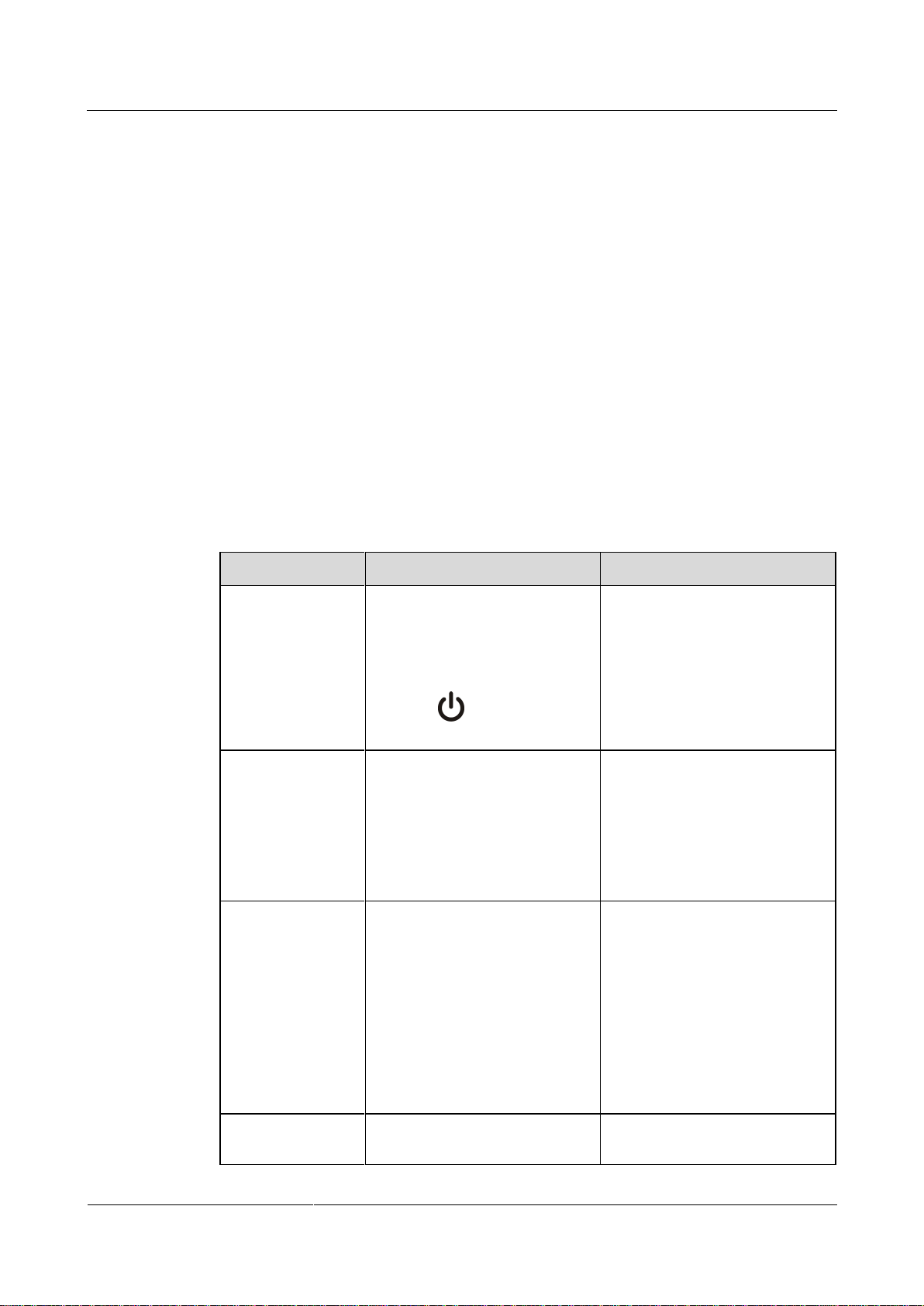
To power on the endpoint, slide the power switch on the rear panel to the ON position.
To power off the endpoint, perform either of the following operations:
Press on the remote control. Confirm the power-off action in the displayed dialog
box.
Slide the power switch on the rear panel to the OFF position.
When the endpoint is powered off using the remote control, the indicator on the front panel turns orange,
but the power switch on the rear panel is still in the ON position. To power on the endpoint again, press
on the remote control.
Depending on the endpoint's status, the indicators on the front panel may blink in different
colors and at different rates, as listed in Table 2-1 and Table 2-2.
Table 2-1 Status indicator description
Page 20

HUAWEI TE80 Videoconferencing Endpoint
Administrator Guide
2 Basic Configuration and Verification
Issue 02 (2014-03-30)
Huawei Proprietary and Confidential
Copyright © Huawei Technologies Co., Ltd.
12
Table 2-2 Alarm indicator description
When the Alarm Indicator
Is...
The Endpoint Is...
Blinking red twice per second
Overheated.
Blinking red four times per
second
Encountering a temperature fault. For example, the
temperature sensor inside the endpoint cannot sense the
current operating temperature, causing fast fan rotation
speed and loud fan noise.
Parameter
Description
Setting
Sites
Specifies the name of your site. The site
name is superimposed on the local video.
When your site joins a multipoint
conference, this site name is displayed in
the site list.
Default value: site
Language
Specifies the language for the remote
controlled UI.
Default value: English
Time zone
Specifies the time difference between the
local time and the Greenwich Mean
Time (GMT).
The endpoint automatically sets this
parameter based on the country or region
Default value:
2.2 Using the Wizard
The Wizard helps you quickly set the general, network, and camera parameters on your
endpoint.
Background
When configuring the endpoint for the first time, you can connect to the NMS server to
configure the endpoint. If the NMS server has not been configured or obtaining the NMS
server settings times out, perform the steps in this section to set the required parameters.
Procedure
Step 1 Choose Advanced > Settings > Installation > Wizard.
Step 2 Set the general parameters described in Table 2-3 and Table 3-3.
If a USB flash drive is provided with your endpoint, you can also load the configuration file
from the USB flash drive to configure your endpoint.
The General screen is displayed.
Table 2-3 General parameters
Page 21
HUAWEI TE80 Videoconferencing Endpoint
Administrator Guide
2 Basic Configuration and Verification
Issue 02 (2014-03-30)
Huawei Proprietary and Confidential
Copyright © Huawei Technologies Co., Ltd.
13
Parameter
Description
Setting
where your site is located.
Time format
Specifies the format in which time is
displayed.
Default value: 24-hour
System time
Specifies the system time.
Set the system time to your
local time to ensure appropriate
use of system functions, such
as joining conferences on time
and recording accurate event
occurrence time in logs.
Step 3 Select Next, Set the H.323 parameters described in Table 3-4.
Step 4 Select Next. Set the Session Initiation Protocol (SIP) parameters described in Table 3-5.
Step 5 Select Next. Set the video input parameters described in Table 4-14.
Step 6 Select Save.
----End
2.3 Verifying the Basic Configuration
After completing the basic configuration, you must verify it by performing call, sound, and
image tests.
2.3.1 Call Test
By performing a call test, you can check whether the network is functioning and whether the
endpoint has registered with the GK or SIP server.
Procedure
Step 1 Press on the remote control.
The call screen is displayed.
Step 2 In the text box, enter the IP address or number of a remote site.
Step 3 On the remote control, press or to place a call to the remote site.
----End
If you have selected the Enable GK or Register with server parameter and set other required
parameters but the endpoint fails to register with the GK or SIP server, or is
displayed in the lower right corner of the call screen.
Page 22

HUAWEI TE80 Videoconferencing Endpoint
Administrator Guide
2 Basic Configuration and Verification
Issue 02 (2014-03-30)
Huawei Proprietary and Confidential
Copyright © Huawei Technologies Co., Ltd.
14
Verification Result
If you successfully place a call to the remote site using its IP address, the IP network is
functioning properly.
If you successfully place a call to an H.323 site, the endpoint has registered with the GK
server.
If you successfully place a call to a SIP site, the endpoint has registered with the SIP
server.
2.3.2 Sound Test
By performing a sound test, you can check whether the audio input and output of the endpoint
is correct.
Prerequisites
The endpoint has been connected to an audio input device such as a microphone.
The endpoint has been connected to an audio output device, such as a speaker, or
connected to a television using an HDMI cable.
Procedure
Step 1 Choose Advanced > Diagnostics > Sound and Color Bar Test from the option bar.
Step 2 Select Sound Test.
----End
Verification Result
If the speaker emits a "ding ding" tone when there is no audio input, the audio output of
the endpoint is correct.
If audio inputs, for example human voices, are received from the microphone and the
speaker emits the voices, the audio input and output of the endpoint are correct.
2.3.3 Image Test
By performing an image test, you can check whether the video input and output of the
endpoint is correct.
Prerequisites
The endpoint has been connected to video sources and a display device.
Procedure
Step 1 Choose Advanced > Settings > Video > Common Settings > Video Input from the option
bar. Set the Video Source parameter to the video input ports to which video sources are
connected.
Step 2 Check whether the videos from connected video sources are correctly displayed on the display
device.
----End
Page 23
HUAWEI TE80 Videoconferencing Endpoint
Administrator Guide
2 Basic Configuration and Verification
Issue 02 (2014-03-30)
Huawei Proprietary and Confidential
Copyright © Huawei Technologies Co., Ltd.
15
Verification Result
Parameter
Description
Setting
Shut Down
Specifies whether the endpoint
can be powered off.
If you disable this parameter,
you can only restart the endpoint
or place it in sleep mode by
pressing on the remote
control.
The default value is Enable.
Enter sleep mode
Specifies the period after which
the endpoint enters sleep mode if
you do not perform any
operations.
If you set this parameter to
Never, the endpoint will never
automatically enter sleep mode.
The default value is After 10
min.
Wake-on-LAN
Specifies whether you can
remotely wake up a standby or
sleeping endpoint by sending
Wake on LAN (WOL) messages.
NOTE
A standby endpoint indicates that
the power switch on the endpoint's
rear panel is in the ON position and
that the endpoint is turned off by
pressing the power key on the
remote control.
This parameter is not selected by
default.
Scheduled
power-on
Specifies whether the endpoint
automatically powers on at the
This parameter is not selected by
default.
This example assumes that a video source is connected to the 1 MAIN IN port on the endpoint.
If the video delivered through the 1 MAIN IN port is correctly displayed on the display device
after you select 1 MAIN IN, the video input and output of the endpoint are correct.
2.4 Power Management
The endpoint supports sleep mode. You can set its sleep time and automatic startup and
shutdown time.
To reduce power consumption, the endpoint can be configured to enter sleep mode after it has
been in the idle state for a defined period of time.
Procedure
Step 1 Choose Advanced > Settings > General > Power supply. Set the sleep and automatic startup
and shutdown parameters described in Table 2-4.
Table 2-4 Sleep and automatic startup and shutdown parameters
Page 24
HUAWEI TE80 Videoconferencing Endpoint
Administrator Guide
2 Basic Configuration and Verification
Issue 02 (2014-03-30)
Huawei Proprietary and Confidential
Copyright © Huawei Technologies Co., Ltd.
16
Parameter
Description
Setting
specified time.
NOTE
If you enable this function, you
must also set Scheduled power-on
time (hh:mm).
Scheduled
power-on time
Specifies the time when the
endpoint automatically powers
on.
The value format depends on the
value set for Time format.
The default value is 0:0, which
corresponds to the 24-hour value
for Time format.
Scheduled
power-off
Specifies whether the endpoint
automatically powers off at the
specified time.
NOTE
If you enable this function, you
must also set Scheduled power-off
time (hh:mm).
This parameter is not selected by
default.
Scheduled
power-off time
Specifies the time when the
endpoint automatically powers
off.
The value format depends on the
value set for Time format.
The default value is 0:0, which
corresponds to the 24-hour value
for Time format.
Step 2 Select Save.
The endpoint enters sleep mode, and the LED indicator blinks purple once every 2 seconds.
----End
To directly place the endpoint in sleep mode, press on the remote control and select Sleep.
Follow-up Procedure
The endpoint wakes up from sleep mode in response to any of the following conditions:
You use the touch panel.
An endpoint upgrade starts.
A presentation source is connected to the endpoint.
The camera forwards infrared signals to the endpoint.
The WOL function is used.
The clock matches the scheduled endpoint startup time.
The endpoint receives a call.
You use the remote control.
You log in to the endpoint web interface.
Page 25

HUAWEI TE80 Videoconferencing Endpoint
Administrator Guide
2 Basic Configuration and Verification
Issue 02 (2014-03-30)
Huawei Proprietary and Confidential
Copyright © Huawei Technologies Co., Ltd.
17
When the clock matches the scheduled automatic shutdown time, the endpoint displays a
dialog box and begins a 10-second countdown. If you select No, the endpoint will not power
off. If you select Yes, or do not select any option within 10 seconds, the endpoint
automatically powers off.
Page 26

HUAWEI TE80 Videoconferencing Endpoint
Administrator Guide
3 Network
Issue 02 (2014-03-30)
Huawei Proprietary and Confidential
Copyright © Huawei Technologies Co., Ltd.
18
About This Chapter
Indicator Status
Connection Status
The orange indicator blinks once
at a time.
The LAN port is in 10 M network port mode.
The orange indicator blinks twice
The LAN port is in 100 M network port mode.
This chapter describes the hardware connection to network devices and the settings on
relevant screens required when the endpoint is used in different communication networks.
3.1 Connecting to an IP LAN Network
To implement video communication over an IP local area network (LAN), you must connect
the endpoint to the IP LAN.
3 Network
3.2 Connecting to a 4E1 Network
Only the TE80 supports 4E1 functions. To implement video communication over a 4E1-line
dedicated network, you must connect the TE80 to the network.
3.1 Connecting to an IP LAN Network
To implement video communication over an IP local area network (LAN), you must connect
the endpoint to the IP LAN.
To connect to an IP LAN, use an IP network cable to connect the LAN 1 port on the
endpoint's rear panel to the network port on a LAN device.
3.1.1 Checking Status Indicators of the LAN Port
The status indicators on the LAN port can quickly provide information about the current
network connection.
There are two indicators working together to indicate the network connection, as shown in
Table 3-2.
Table 3-1 LAN status indicators of TE80
Page 27

HUAWEI TE80 Videoconferencing Endpoint
Administrator Guide
3 Network
Issue 02 (2014-03-30)
Huawei Proprietary and Confidential
Copyright © Huawei Technologies Co., Ltd.
19
Indicator Status
Connection Status
at a time.
The orange indicator blinks thrice
at a time.
The LAN port is in 1000 M network port mode.
The green indicator is steady on.
The endpoint is connected to a network.
The green indicator blinks.
Data is being transmitted. The green indicator turns
off each time a frame of data has been transmitted.
The green indicator is off.
No data is being transmitted or the network is not
reachable.
Parameter
Description
Setting
Local IP address
Network
interface
mode
Specifies the working mode for the
network ports on the endpoint.
Auto detection: When accessing the
network, the endpoint automatically
negotiates with a remote network
device to determine the optimal work
mode.
10 Mbps and half duplex: The data
transmission rate is 10 Mbit/s, and
data cannot be sent and received at
the same time.
10 Mbps and full duplex: The data
transmission rate is 10 Mbit/s, and
data can be sent and received at the
same time.
100 Mbps and half duplex: The data
transmission rate is 100 Mbit/s, and
data cannot be sent and received at
the same time.
100 Mbps and full duplex: The data
transmission rate is 100 Mbit/s, and
data can be sent and received at the
The default value is Auto
detection.
NOTE
When you do not know the
network port working mode of a
remote network device, set this
parameter to Auto detection.
Otherwise, the endpoint may fail
to access the network.
3.1.2 Setting IP Parameters
To enable video communication over an IP LAN network, you must set the IP parameters of
the endpoint, such as the DNS server address, network mode, and gateway IP address.
Procedure
Step 1 Choose Advanced > Settings > Network > IP. Set the parameters listed in Table 3-3.
Table 3-2 IP parameters
Page 28

HUAWEI TE80 Videoconferencing Endpoint
Administrator Guide
3 Network
Issue 02 (2014-03-30)
Huawei Proprietary and Confidential
Copyright © Huawei Technologies Co., Ltd.
20
Parameter
Description
Setting
same time.
1000Mbps and full duplex: The data
transmission rate is 1000 Mbit/s, and
data can be sent and received at the
same time.
Hub
network port
mode
The endpoint can function as a hub in
this mode, enabling the devices
connected to its two network ports to
communicate with each other.
When the endpoint is connected to the
Internet, devices connected to the
network ports on the endpoint can also
access the Internet.
The default value is Disable.
Connection
type
Specifies the mode in which the
endpoint obtains an IP address.
Static IP: The network administrator
assigns an IP address to the endpoint.
If you select this option, you must
also set Local IP address, Subnet
mask, and Gateway address.
Dynamic IP: When a DHCP server
is available on the network, the
endpoint automatically obtains an IP
address using the Dynamic Host
Configuration Protocol (DHCP).
The default value is Static IP.
Local IP
address
Specifies the endpoint IP address.
The default value is 192.168.1.1
Examples:
IPv4: 192.168.1.10
IPv6:
2000:0:0:0:200:55:26:1
Obtain the IP address from the
network administrator.
Subnet mask
Specifies the subnet mask for the
endpoint IP address. A subnet mask
divides the IP address into a network
address and a host address.
The default value is
255.255.255.0
Obtain the subnet mask from
the network administrator.
Gateway
address
Specifies the gateway address that
corresponds to the endpoint IP address.
Examples:
IPv4: 192.168.1.1
IPv6: 2000:0:0:0:200:55:0:1
Obtain the gateway address
from the network administrator.
IPv6
If you select IPv6, you must also set
Connection type, Local IP address,
Subnet prefix length, and Gateway
address.
This parameter is not selected
by default.
Page 29

HUAWEI TE80 Videoconferencing Endpoint
Administrator Guide
3 Network
Issue 02 (2014-03-30)
Huawei Proprietary and Confidential
Copyright © Huawei Technologies Co., Ltd.
21
Parameter
Description
Setting
Subnet
prefix length
Specifies the number of the digit 1 in a
subnet mask that is converted into binary
mode.
The default value is 0.
PPPoE
Dialing
Specifies whether the endpoint accesses
broadband networks using dial-up
connections.
NOTE
If you set this parameter to Enable, you must
also set Dialing mode, User name, and
Password.
The default value is Disable.
Dialing
mode
Specifies the dial-up connection mode.
The dial-up process complies with the
Point-to-Point Protocol over Ethernet
(PPPoE) protocol. To use a dial-up
connection, in User name and
Password enter the user name and
password that are provided by your
broadband access service provider.
Auto: When the endpoint starts, it
automatically sets up a dial-up
connection over the IP network. If the
dial-up service is not free of charge,
charging starts when the dial-up
connection is established.
Manual: The endpoint uses the
dial-up program to access To set up a
PPPoE dial-up connection, choose
Advanced > Utilities > PPPoE
Dialing > Connect.
The default value is Auto.
DNS server
address 1
DNS server
address 2
DNS server
address 3
Specifies the DNS server IP address.
After you set this IP address, domain
names can be used for the GK server
address and the SIP server address. The
DNS server will translate the domain
names to the IP addresses of the GK
server and the SIP server.
Example: 202.98.192.67
Obtain the IP address from the
network administrator.
Alternate IP address
Alternate IP
address
Subnet mask
Specifies the alternate IP address of the
endpoint. This IP address cannot be in
the same network segment as Local IP
address (described in the Local IP
address section in this table) or the IP
address of the gatekeeper (GK) server.
No default value is set for this
parameter.
Obtain the IP address from the
network administrator.
Step 2 Select Save.
----End
Page 30

HUAWEI TE80 Videoconferencing Endpoint
Administrator Guide
3 Network
Issue 02 (2014-03-30)
Huawei Proprietary and Confidential
Copyright © Huawei Technologies Co., Ltd.
22
3.1.3 Setting H.323 Parameters
Parameter
Description
Setting
Enable GK
Specifies whether the endpoint registers
with the GK.
If this parameter is selected, when
your endpoint starts, it registers with
the specified GK. An endpoint that
registers with a GK can place calls to
remote sites using their IP addresses
or site numbers if the remote sites
also register with GKs. A GK must
be used to initiate a conference
attended by IP and integrated services
digital network (ISDN) sites.
If this parameter is not selected, your
endpoint does not register with the
GK. To call another endpoint through
H.323, your endpoint can only use
the called endpoint's IP address.
NOTE
If you select Enable GK, you must also set
GK registration mode, Site number, H.323
ID, and Password.
This parameter is not selected
by default.
GK
registration
mode
Auto: Your endpoint automatically
registers with an available GK on the
network and obtains the GK address.
Manual: You must set GK address,
The default value is Auto.
The H.323 parameters must be set when the GK is used in the conference system.
Prerequisites
The GK is used in the conference system.
Context
When the GK is used in the conference system, the endpoint can be configured with a site
number. Other endpoints that also have registered with the GK can then use the site number as
well as the IP address to call your endpoint.
The GK is the network isolator of the videoconferencing system and is used to manage the network
bandwidth, endpoint authentication, and address translation. It enables calls to be made to fixed site
names rather than changeable IP addresses.
Procedure
Step 1 Choose Advanced > Settings > Network > IP > H.323, and then set the parameters listed in
Table 3-4.
Table 3-3 H.323 parameters
Page 31

HUAWEI TE80 Videoconferencing Endpoint
Administrator Guide
3 Network
Issue 02 (2014-03-30)
Huawei Proprietary and Confidential
Copyright © Huawei Technologies Co., Ltd.
23
Parameter
Description
Setting
which specifies the GK with which
you want your endpoint to register.
GK address
Specifies the IP address or domain name
of the server where the desired GK is
installed.
If you set this parameter to the domain
name, you must enable the DNS server
and set correct mapping information on
the server.
This parameter is mandatory only when
GK registration mode is set to Manual.
Example: 192.168.1.10
Site number
Specifies the site number for your
endpoint.
If your endpoint registers with a GK,
endpoints that also register with GKs can
dial this site number to call your
endpoint.
Enter a string of 1 to 32 digits.
Example: 12345
H.323 ID
Specifies the name by which a GK
identifies your endpoint after your
endpoint registers with the GK.
The name can consist of digits,
letters, and special characters,
such as @ # %.
Example: ab3@
For successful GK
authentication, the name
defined on your endpoint must
be consistent with the name
predefined on the GK.
Authenticati
on user
name
Specifies the user name used for H.323
authentication.
This parameter is available only when
encryption is enabled. To enable
encryption, choose Advanced >
Settings > Security > Encryption, and
set Encryption to Enable.
Obtain the user name from your
IP network service provider.
This user name must be the
same as the value of H.323 ID.
Password
Specifies the password your endpoint
uses to register with a GK. The GK uses
this password to authenticate your
endpoint.
Obtain the password from your
IP network service provider.
For successful GK
authentication, the password
defined on your endpoint must
be consistent with the password
predefined on the GK.
Huawei GK
Specifies whether your endpoint uses a
Huawei GK.
If you do not select Huawei GK, some
functions, such as Conference Control
and SiteCall are unavailable on your
endpoint.
This parameter is selected by
default.
Do not select this parameter if
your endpoint needs to
interwork with other
manufacturers' devices.
Page 32

HUAWEI TE80 Videoconferencing Endpoint
Administrator Guide
3 Network
Issue 02 (2014-03-30)
Huawei Proprietary and Confidential
Copyright © Huawei Technologies Co., Ltd.
24
Parameter
Description
Setting
HTTPS
mode
Specifies whether to upload SiteCall
conference information using HTTPS
encryption.
This parameter is available only when
Huawei GK is selected.
If this parameter is set to disabled,
your endpoint will use the Transfer
Control Protocol (TCP) to upload
SiteCall conference information,
which may be insecure.
This parameter is not selected
by default.
To improve communication
security, select this parameter.
Multipoint
conference
authenticatio
n
Specifies whether to authenticate servers
when the SiteCall function is used.
This parameter is available only when
HTTPS mode is selected.
This parameter is not selected
by default.
To improve communication
security, select this parameter.
Use VoIP
gateway
VoIP
gateway
address
Specify whether your endpoint can place
calls to the PSTN endpoints connected to
the specified voice over IP (VoIP)
gateway.
If you select Use VoIP gateway, you
must also set VoIP gateway address.
The Use VoIP gateway is not
selected by default.
Parameter
Description
Setting
Register
with server
Specifies whether your endpoint registers
with a SIP server.
If this parameter is selected, an
endpoint that registers with a SIP
This parameter is not selected
by default.
Step 2 Select Save.
----End
3.1.4 Setting SIP Parameters
When the Session Initiation Protocol (SIP) is used for video communications, the SIP
parameters of the endpoint, such as whether to register with the SIP server, must be set.
Prerequisites
Both parties of the conference support SIP.
Procedure
Step 1 Choose Advanced > Settings > Network > IP > SIP, and then set the parameters listed in
Table 3-5.
Table 3-4 SIP parameters
Page 33

HUAWEI TE80 Videoconferencing Endpoint
Administrator Guide
3 Network
Issue 02 (2014-03-30)
Huawei Proprietary and Confidential
Copyright © Huawei Technologies Co., Ltd.
25
Parameter
Description
Setting
server can place calls to remote sites
using their IP addresses or site
numbers if the remote sites also
register with SIP servers.
If this parameter is not selected, your
endpoint does not register with the
SIP server. To call another endpoint
through SIP, your endpoint can only
use the called endpoint's IP address.
NOTE
If you select this parameter, you must also set
Server address, Conference service
number, Site number, User name, and
Password.
Server
address
Specifies the IP address or domain name
of the SIP server with which you want
the endpoint to register.
If you set this parameter to the SIP server
domain name, enable the domain name
server (DNS). If the DNS is not enabled,
enable Proxy server.
Example: 192.168.1.10
Conference
service
number
Specifies the conference service number
for your endpoint to initiate conferences
over an IP multimedia subsystem (IMS)
network.
Set this parameter to the conference
service number obtained from the
administrator of the IMS network.
NOTE
For details about how to set parameters for
interworking with the IMS and joining a
conference on the IMS network, see 6.4
Joining an HD-Video Conference over an
IMS Network.
No default value is set for this
parameter.
Enable
proxy server
Specifies whether to enable the proxy
server.
Select this parameter when the network
environment requires the proxy server or
when Server address is set to the SIP
server domain name but the configured
DNS server fails to resolve this domain
name or the DNS server is not
configured.
NOTE
If you select this parameter, you must also set
Proxy server address, Site number, User
name, and Password.
This parameter is not selected
by default.
Set this parameter based on the
actual SIP network
environment.
Proxy server
address
Specifies the address of the proxy server.
If you set Server address to the SIP
Example: 192.168.1.10
Page 34

HUAWEI TE80 Videoconferencing Endpoint
Administrator Guide
3 Network
Issue 02 (2014-03-30)
Huawei Proprietary and Confidential
Copyright © Huawei Technologies Co., Ltd.
26
Parameter
Description
Setting
server domain name, set this parameter
to the IP address bound to that domain
name.
Site number
Specifies the site number for your
endpoint. If your endpoint registers with
a SIP server, endpoints that also register
with the SIP server can dial this site
number to call your endpoint.
Enter a value containing any of
the following: letters, digits,
special characters such as @
# %.
Example: 12345
User name
Specifies the user name for
authentication registration.
Example: ab3@
Obtain the value of this
parameter from the SIP server
administrator.
Password
Specifies the password that your
endpoint uses to register with a SIP
server.
For successful authentication on a SIP
server, this password set on your
endpoint must be the same as that set on
the SIP server.
Obtain the value of this
parameter from the SIP server
administrator.
Server type
Specifies the SIP server type.
OCS: Select this option if your
endpoint registers with the Microsoft
Office Communications Server
(OCS) or Microsoft Lync Server.
CISCO VCS: Select this option if
your endpoint registers with the Cisco
TelePresence Video Communication
Server (VCS).
Standard: Select this option if your
endpoint registers with other SIP
servers.
The default value is Standard.
Transmissio
n type
Specifies the protocol used for SIP
signaling transmission.
TCP: Use the Transmission Control
Protocol (TCP) to implement
transmission reliability.
UDP: Use the User Datagram
Protocol (UDP) to implement
transmission with reduced latency.
TLS: Use Transport Layer Security
(TLS) to implement transmission
security. If you select this option, you
can import a root certificate from the
Web interface when your endpoint
registers with a SIP server. For
details, see 9.3.7 Importing a
The default value is UDP.
Page 35

HUAWEI TE80 Videoconferencing Endpoint
Administrator Guide
3 Network
Issue 02 (2014-03-30)
Huawei Proprietary and Confidential
Copyright © Huawei Technologies Co., Ltd.
27
Parameter
Description
Setting
Certificate.
Video
request
handling
Specifies how your endpoint handles
video requests from a remote endpoint
during a point-to-point SIP audio call or
multipoint conference.
Accept automatically: Your
endpoint automatically accepts video
requests from the remote endpoint.
Reject automatically: Your endpoint
automatically rejects video requests
from the remote endpoint.
Manual: Your endpoint prompts you
to accept video requests from the
remote endpoint.
The default value is Manual.
Parameter
Description
Setting
Connection type
Specifies the mode in which
the endpoint obtains an IP
address.
Static IP: The network
administrator assigns an
IP address to the
The default value is
Dynamic IP.
Select Dynamic IP unless
special network
requirements are imposed.
Step 2 Select Save.
----End
3.1.5 Setting Wi-Fi Parameters
To use your endpoint to implement video communication over a Wi-Fi network, set the Wi-Fi
parameters.
Setting Wi-Fi Client Parameters
When the Wi-Fi client function is enabled, your endpoint functions as a Wi-Fi client and
access an available Wi-Fi network after connecting to a wireless router.
Step 1 Choose Advanced > Settings > Network > Wi-Fi > Wi-Fi Client. Select Enable for the
Wi-Fi Client parameter.
Your endpoint automatically scans for available wireless routers and lists them in the
Wireless access point list box.
If you need to set a static IP address for your endpoint, go to Step 2. Otherwise, go to Step 4.
Step 2 Select Advanced. On the displayed Advanced Wireless Settings screen, set IP parameters
described in Table 3-6.
Table 3-5 Wi-Fi parameters
Page 36

HUAWEI TE80 Videoconferencing Endpoint
Administrator Guide
3 Network
Issue 02 (2014-03-30)
Huawei Proprietary and Confidential
Copyright © Huawei Technologies Co., Ltd.
28
Parameter
Description
Setting
endpoint. If you select
this option, you must
also set Local IP address,
Subnet mask, and
Gateway address.
Dynamic IP: The
endpoint automatically
obtains an IP address
over the Dynamic Host
Configuration Protocol
(DHCP). If you select
this option, a DHCP
server must be available
on the network.
Local IP address
Specifies the IP address for
the endpoint to connect to a
wireless access point to
implement communication.
Example: 192.168.1.10
This IP address and the IP
address of the wireless
access point must be on the
same network segment. For
example:
If the IP address of the
wireless access point is
192.168.1.100 and its subnet
mask is 255.255.255.0, set
Local IP address to
192.168.1.X. X can be any
integer ranging from 0 to
255 except 100.
Subnet mask
Specifies the subnet mask
for the IP address of your
endpoint. A subnet mask
divides the IP address into a
network address and a host
address.
Example: 255.255.255.0
Gateway address
Specifies the gateway
address that corresponds to
the IP address of the
endpoint.
Example: 192.168.1.1
Step 3 Select Save.
Step 4 From Wireless access point, select the wireless router you want to connect to.
Step 5 Press on the remote control. When prompted, enter the security key or password and
select Connect.
When the endpoint is connected to the router, the Connection Status changes to .
----End
Page 37

HUAWEI TE80 Videoconferencing Endpoint
Administrator Guide
3 Network
Issue 02 (2014-03-30)
Huawei Proprietary and Confidential
Copyright © Huawei Technologies Co., Ltd.
29
Setting Wi-Fi Hotspot Parameters
Parameter
Description
Setting
SSID
Number
Specifies the name of your endpoint's
Wi-Fi network.
Default value for the TE80:
TE80_wifi_ap
The value is a string of 1 to 31
characters, consisting of digits,
letters, and special characters,
such as @ # %.
Channel
Specifies a channel that transmits data
through Wi-Fi signals.
If you select Auto, your endpoint
automatically selects the optimal
channel.
The default value is Auto.
Retain the default value.
Identity
authenticatio
n mode
The first parameter specifies the identity
authentication mode used on the Wi-Fi
network. The second parameter specifies
the data encryption mode corresponding
to the identity authentication mode
adopted.
OPEN: If you select this option for
Encryption mode, the values
available for Encryption mode are
NONE and WEP.
SHARE: If you select this option for
Encryption mode, the value
available for Encryption mode is
WEP.
WPA-PSK: If you select this option
for Encryption mode, the values
available for Encryption mode are
TKIP and AES.
WPA2-PSK: If you select this option
for Encryption mode, the values
available for Encryption mode are
TKIP and AES.
The default value is
WPA2-PSK.
Wi-Fi Protected Access (WPA)
provides greater security than
Wired Equivalent Privacy
(WEP). Therefore, set Identity
authentication mode to
WPA-PSK or WPA2-PSK.
NOTE
When the endpoint is connected to
a VPM220W, you must set
Identity authentication mode to
WPA-PSK or WPA2-PSK.
Encryption
mode
Specifies the encryption method used on
the Wi-Fi network. The required key
types vary depending on your settings of
Default value: AES
When the Wi-Fi hotspot function is enabled on the endpoint, other devices, such as
VPM220Ws, tablets, and PCs, can access a Wi-Fi network by connecting to the endpoint.
Step 1 Choose Advanced > Settings > Network > Wi-Fi > Wi-Fi Hotspot. Select Enable for the
Wi-Fi Hotspot parameter.
Step 2 Select Advanced. On the displayed Advanced Wireless Settings screen, set the advanced
wireless network parameters described in Table 3-7.
Table 3-6 Advanced wireless network parameters
Page 38

HUAWEI TE80 Videoconferencing Endpoint
Administrator Guide
3 Network
Issue 02 (2014-03-30)
Huawei Proprietary and Confidential
Copyright © Huawei Technologies Co., Ltd.
30
Parameter
Description
Setting
this parameter. If you set Encryption
mode to NONE, the Wi-Fi network
provided by your endpoint is open to
everyone.
Password
Specifies the password used by other
devices to connect to your endpoint.
The required password varies
depending on your settings of
Encryption mode.
If you set Encryption mode
toAES or TKIP, the default
value of the password is
Change_Me.
If you set Encryption mode
to WEP, the default value
of the password is
wifi_ap_wep_1.
If you set Encryption mode
to NONE, the Wi-Fi
network provided by your
endpoint is open to
everyone.
Local IP
address
Subnet mask
Specify the IP address and subnet mask
of your endpoint.
Default values:
Local IP address:
192.168.2.1
Subnet mask:
255.255.255.0
DHCP
Specifies whether your endpoint assigns
IP addresses to devices connected to it.
NOTE
If you select this parameter, you must also set
Start IP address and End IP address.
This parameter is selected by
default.
Start IP
address
End IP
address
Specify the IP address segment for the
devices connected to your endpoint.
Default values:
Start IP address:
192.168.2.10
End IP address:
192.168.2.100
Step 3 Select Save.
In the Connected devices list box, you can view the MAC and IP addresses of all the devices
connected to your endpoint.
----End
Page 39

HUAWEI TE80 Videoconferencing Endpoint
Administrator Guide
3 Network
Issue 02 (2014-03-30)
Huawei Proprietary and Confidential
Copyright © Huawei Technologies Co., Ltd.
31
3.2 Connecting to a 4E1 Network
1 Captive screw
2 4E1 port (RJ45)
3 Edge connector
Only the TE80 supports 4E1 functions. To implement video communication over a 4E1-line
dedicated network, you must connect the TE80 to the network.
Do not connect outdoor cables directly to the TE80. If outdoor E1 lines (unbalanced) are
led indoors, surge protectors are required. Any questions, contact technical support
personnel.
The connection of E1 lines must comply with grounding specifications. For details, see A
E1 and T1 Grounding Criteria.
A 4E1 interface card provides four balanced-output ports. If the TE80 has a 4E1 interface card
installed, connect the TE80 to a 4E1-line dedicated network.
The ports of a 4E1 interface card can be used for any of the four E1 lines. There is no
mapping between the ports and the four E1 lines on the local and the remote ends, so the lines
can be connected to any of the ports at the local and remote ends, as long as all the four lines
are connected.
3.2.1 Inserting a 4E1 Interface Card
To hold conferences over a 4E1 network, you must insert a 4E1 interface card into the
corresponding interface slot at the back of the TE80.
For safety reasons, insert the interface card only when the TE80 is powered off.
Figure 3-1 shows the appearance of a 4E1 interface card, for your reference only.
Figure 3-1 4E1 interface card
Page 40

HUAWEI TE80 Videoconferencing Endpoint
Administrator Guide
3 Network
Issue 02 (2014-03-30)
Huawei Proprietary and Confidential
Copyright © Huawei Technologies Co., Ltd.
32
To avoid damage to the interface card, implement antistatic measures before touching the card,
such as wearing an ESD wrist strap, as shown in Figure 3-2.
Figure 3-2 Wearing an ESD wrist strap
Procedure
Insert the interface card, as shown in Figure 3-3.
Figure 3-3 Inserting an interface card
1. Loosen the two screws and remove the cover panel of the interface card slot.
2. Take out the interface card from its package. Slide the interface card into the card slot
while keeping the side with components facing upwards.
3. Fasten the screws on the interface card.
Page 41

HUAWEI TE80 Videoconferencing Endpoint
Administrator Guide
3 Network
Issue 02 (2014-03-30)
Huawei Proprietary and Confidential
Copyright © Huawei Technologies Co., Ltd.
33
3.2.2 Checking Status Indicators on the 4E1 Ports
Indicator Status
Connection Status
The orange indicator is
on.
The lines are connected and the clocks on the lines are
synchronous.
The green indicator is
on.
A call can be placed.
Parameter
Description
Setting
Account
Password
Specifies the user name and
password the TE80 uses to place
an H.320 call.
Obtain the user name and password
from the videoconferencing system
administrator.
Clock mode
Specifies the clock mode used by
the TE80. The following clock
If the TE80 is connected to an
MCU, set the MCU clock as the
The status indicators on the 4E1 ports can quickly provide information about the current
network connection.
There are two indicators on the 4E1 port to indicate the network connection, as shown in
Table 3-8.
Table 3-7 Status indicator on the 4E1 port
3.2.3 Setting 4E1 Parameters
If 4E1 lines are used for video communication, you must set 4E1 parameters such as the
account, password, clock mode, signaling mode, and sensitivity.
Prerequisites
Context
Procedure
Step 1 Choose Advanced > Settings > Network > 4E1/E1. Set the parameters listed in Table 3-9.
Before setting 4E1 parameters, ensure that 4E1 lines are used by the TE80.
If the TE80 has a 4E1 interface card installed, the TE80 automatically detects the interface
card type and displays the corresponding configuration screen. For parameter details, contact
your network service provider.
If 4E1 lines are faulty and if automatic backup is available, the endpoint uses the backup line
preferentially, and then reduces the conference rate automatically. The endpoint can perform
automatic backup, automatic rate reduction, or automatic rate increase in one second. During
the process, erratic display may occur on the video and noise may exist. After two seconds,
however, the video and the audio will be recovered and the conference rate remains
unchanged.
Table 3-8 4E1 parameters
Page 42

HUAWEI TE80 Videoconferencing Endpoint
Administrator Guide
3 Network
Issue 02 (2014-03-30)
Huawei Proprietary and Confidential
Copyright © Huawei Technologies Co., Ltd.
34
Parameter
Description
Setting
modes are available:
Preferred clock: The TE80
uses its internal clock and
provides the clock to the
endpoint connected to its 4E1
port. To place a point-to-point
call, set Clock mode for either
endpoint to Preferred clock.
Alternate clock 1/Alternate
clock 2/Alternate clock
3/Alternate clock 4: The TE80
obtains a clock from any of
these lines.
master clock and the TE80 clock
as the slave clock.
If the TE80 is connected to another
endpoint, set one endpoint's clock
as the master clock and the other's
to slave clock.
Signaling
mode
Specifies the transmission mode
for 4E1 signaling.
The Cyclic Redundancy Check
(CRC) is used to test the network
quality, and CRC results indicate
frame error rates. When you select
an option that contains CRC4, the
TE80 tests the network for bit
errors.
To use channel associated
signaling, select CAS.
To use common channel signaling,
select CCS.
Sensitivity
Specifies the sensitivity of the
receive equalizer.
Set this parameter based on the
length of the 4E1 line used
between the TE80 and the nearest
network node such as a switch.
If the length of the 4E1 line used
between the TE80 and the nearest
network node exceeds 100 meters,
select Long line.
If the length of the 4E1 line used
between the TE80 and the nearest
network node is less than 100
meters, you can select Long line
or Short line. Long line is
recommended because it provides
a higher sensitivity.
Step 2 Select Save.
----End
Page 43

HUAWEI TE80 Videoconferencing Endpoint
Administrator Guide
4 Display Device and Camera
Issue 02 (2014-03-30)
Huawei Proprietary and Confidential
Copyright © Huawei Technologies Co., Ltd.
35
4 Display Device and Camera
About This Chapter
To bring an impressive video experience, correctly connect video input and output devices to
the video input and output ports on the endpoint and set the video input and output
parameters.
4.1 Connecting a Display Device
When connecting display devices to the endpoint, choose cables based on the related ports.
4.2 Configuring a Display Device
Correctly setting video output parameters and adjusting video display parameters enable a
display device to deliver superior video quality.
4.3 Connecting a Camera
You can view the video delivered by a camera only after correctly connecting the camera to
the endpoint and setting the required video input parameters.
4.4 Configuring Video Input
Correct video input settings enable your endpoint to properly display video input from the
video input ports.
4.5 Selecting and Controlling a Camera
If you have connected multiple video devices to the video input ports, you must select local
and remote video sources from these devices. Then, you can control the local and remote
cameras to view the desired video.
4.6 Setting Camera Presets
Camera presets are camera positions you store ahead of time. Each camera preset stores the
camera pan, tilt, and zoom (PTZ) settings. You can easily control the camera by switching
between its presets.
4.1 Connecting a Display Device
When connecting display devices to the endpoint, choose cables based on the related ports.
Page 44

HUAWEI TE80 Videoconferencing Endpoint
Administrator Guide
4 Display Device and Camera
Issue 02 (2014-03-30)
Huawei Proprietary and Confidential
Copyright © Huawei Technologies Co., Ltd.
36
The video output formats vary according to port types. Table 4-1, Table 4-2, and Table 4-3
Port Name
on the UI
Port
Numbe
r on the
Rear
Panel
Type
Output
Format
Default Settings After
Startup
1 MAIN
OUT
1
HDMI
DVI and HDMI
By default, this port
functions as the main output
port, GUI port, and caption
output port and is used to
display the remote
controlled UI, captions, and
local video. This port can
also be used to switch to
combined pictures.
2 HDMI
OUT
2
HDMI
DVI and HDMI
By default, this port
functions as the auxiliary
output port and is used to
display the local video.
When the Presentation
display function is enabled,
this port is used to display
the local or remote
presentation if a
presentation source is
connected to this port and
display a black screen if no
presentation source is
connected to this port.
3 VGA
OUT
3
VGA
VGA and
YPbPr
By default, this port is used
to display the local video.
Port Name
on the UI
Port
Numbe
r on the
Rear
Panel
Type
Output
Format
Default Settings After
Startup
1 MAIN
OUT
1
HDMI
DVI and HDMI
By default, this port
functions as the main output
port, GUI port, and caption
output port and is used to
display the remote
controlled UI, captions, and
describe the video output ports on the endpoint.
Table 4-1 Capabilities of the TE40's video output ports
Table 4-2 Capabilities of the TE50's video output ports
Page 45

HUAWEI TE80 Videoconferencing Endpoint
Administrator Guide
4 Display Device and Camera
Issue 02 (2014-03-30)
Huawei Proprietary and Confidential
Copyright © Huawei Technologies Co., Ltd.
37
Port Name
on the UI
Port
Numbe
r on the
Rear
Panel
Type
Output
Format
Default Settings After
Startup
local video. This port can
also be used to switch to
combined pictures.
2 HDMI
OUT
2
HDMI
DVI and HDMI
By default, this port
functions as the auxiliary
output port and is used to
display the local video.
When the Presentation
display function is enabled,
this port is used to display
the local or remote
presentation if a
presentation source is
connected to this port and
display a black screen if no
presentation source is
connected to this port.
3 VGA
OUT
3
VGA
VGA and
YPbPr
By default, this port is used
to display the local video.
4 3G-SDI
OUT
4
BNC
SDI
By default, this port is used
to display the local video.
5 SD OUT
5
RCA
CVBS
By default, this port is used
to display the local video.
Port Name
on the UI
Port
Number
on the
Rear
Panel
Type
Output
Format
Default Settings After
Startup
1 MAIN
OUT
1
DVI-I
DVI, VGA,
YPbPr, and
HDMI
By default, this port
functions as the main output
port, GUI port, and caption
output port and is used to
display the remote
controlled UI, captions, and
local video. This port can
also be used to switch to
combined pictures.
2 PC OUT
2
DVI-I
DVI, VGA,
YPbPr, and
By default, this port
functions as the auxiliary
Table 4-3 Capabilities of the TE80's video output ports
Page 46

HUAWEI TE80 Videoconferencing Endpoint
Administrator Guide
4 Display Device and Camera
Issue 02 (2014-03-30)
Huawei Proprietary and Confidential
Copyright © Huawei Technologies Co., Ltd.
38
Port Name
on the UI
Port
Number
on the
Rear
Panel
Type
Output
Format
Default Settings After
Startup
HDMI
output port and is used to
display the local video.
When the Presentation
display function is enabled,
this port is used to display
the local or remote
presentation if a
presentation source is
connected to this port and
display a black screen if no
presentation source is
connected to this port.
NOTE
If you select HDMI and DVI
as the output signal source,
these two ports deliver the
same video. If you select
another type of signal source,
only the DVI-I port delivers
videos.
HDMI
DVI and HDMI
2 SD OUT
2 (DVI-I
port)
DVI-I
S-VIDEO and
CVBS
By default, this port is used
to display the local video.
Connect a display device to
this port using a
DVI-S-Video/VGA/CVBS
cable.
3 DVR
OUT
3
HDMI
DVI and HDMI
By default, this port is used
to display the local video.
4 3G-SDI
OUT
4
BNC
SDI
By default, this port is used
to display the local video.
Selecting Between Ports
When you connect the endpoint to one or more display devices, select ports based on the
content you want to view.
Connecting to one display device
The 1 MAIN OUT port is recommended. Using the default endpoint settings, a display
device connected to the 1 MAIN OUT port can show the local video, presentation,
remote controlled UI, captions, and combined pictures.
Connecting to two display devices
To show the video and presentation independently on two display devices, connect the
two display devices to the 1MAIN OUT and 2 PC OUT ports if you are using the TE80
and to the 1 MAIN OUT and 2 HDMI OUT ports if you are using the TE50 or TE40. A
Page 47

HUAWEI TE80 Videoconferencing Endpoint
Administrator Guide
4 Display Device and Camera
Issue 02 (2014-03-30)
Huawei Proprietary and Confidential
Copyright © Huawei Technologies Co., Ltd.
39
display device shows the local video when connected to the 1 MAIN OUT port and
Output Mode
Video Resolution
1 MAIN OUT
VGA
800 x 600 pixels, 1024 x 768 pixels, 1280 x 1024 pixels, UXGA (1600
x 1200), 1920 x 1200 pixels, 720p, and 1080p
YPbPr
720p, 1080i, and 1080p
DVI
800 x 600 pixels, 1024 x 768 pixels, 1280 x 1024 pixels, UXGA (1600
x 1200), 1920 x 1200 pixels, 720p, 1080i, and 1080p
HDMI
720p, 1080i, and 1080p
2 PC OUT
shows the presentation when connected to the 2 PC OUT port (or 2 HDMI OUT port).
The Presentation display parameter must be enabled in order for this to method to work.
For details, see 4.2.1 Configuring Video Output.
The preceding information describes the recommended connection methods for default
endpoint settings. Select ports based on the actual settings of your endpoint and the
capabilities of its video output ports.
Selecting Between Cables
Use the cable that is provided to connect a display device to the endpoint based on the content
to be displayed and the port on the display device.
Please use the cables provided with the endpoint. Other cables may not be able to ensure the desired
quality. Contact the device supplier to purchase appropriate cables.
4.2 Configuring a Display Device
Correctly setting video output parameters and adjusting video display parameters enable a
display device to deliver superior video quality.
4.2.1 Configuring Video Output
After connecting all the video cables, correctly set the video output parameters, such as the
output mode, resolution, refresh rate, and stretch mode, to deliver superior video quality.
Background
For details about the video output ports on various endpoint models, see 4.1 Connecting a
Display Device.
Table 4-6 list the resolutions supported by the video output ports in each output mode.
Although video is sharper at a higher resolution, the resolution you select must be supported
by the display device used.
Table 4-4 Available video resolutions in each output mode of TE80
Page 48

HUAWEI TE80 Videoconferencing Endpoint
Administrator Guide
4 Display Device and Camera
Issue 02 (2014-03-30)
Huawei Proprietary and Confidential
Copyright © Huawei Technologies Co., Ltd.
40
Output Mode
Video Resolution
VGA
800 x 600 pixels, 1024 x 768 pixels, 1280 x 1024 pixels, UXGA (1600
x 1200), 1920 x 1200 pixels, 720p, and 1080p
YPbPr
720p, 1080i, and 1080p
DVI
800 x 600 pixels, 1024 x 768 pixels, 1280 x 1024 pixels, UXGA (1600
x 1200), 1920 x 1200 pixels, 720p, 1080i, and 1080p
HDMI
720p, 1080i, and 1080p
2 SD OUT
CVBS
NTSC and PAL
S-VIDEO
NTSC and PAL
3 DVR OUT
DVI
800 x 600 pixels, 1024 x 768 pixels, 1280 x 1024 pixels, UXGA (1600
x 1200), 1920 x 1200 pixels, 720p, 1080i, and 1080p
HDMI
720p, 1080i, and 1080p
4 3G-SDI OUT
SDI
720p, 1080i, and 1080p
Video
Resolution
Refresh Rate (Hz)
NTSC
60
PAL
50
800 x 600
pixels
56, 60, 72, 75, or 85
1024 x 768
pixels
60, 70, 75, or 85
1280 x 1024
pixels
60, 75, or 85
UXGA (1600 x
1200)
60
1920 x 1200
pixels
60
Although video is smoother at a higher refresh rate, the refresh rate you select must be
supported by the display device used.
Table 4-7 lists the refresh rates available for each video resolution.
Table 4-5 Available refresh rates for each resolution
Page 49

HUAWEI TE80 Videoconferencing Endpoint
Administrator Guide
4 Display Device and Camera
Issue 02 (2014-03-30)
Huawei Proprietary and Confidential
Copyright © Huawei Technologies Co., Ltd.
41
Video
Resolution
Refresh Rate (Hz)
720p 60, if the output mode is VGA
50 or 60, if the output mode is DVI, YPbPr, or HDMI
1080i
50 or 60
1080p 60, if the output mode is VGA
24, 25, 30, 50, or 60, if the output mode is DVI, YPbPr, or HDMI
Procedure
Parameter
Description
Setting
GUI
Specifies the video output port for the
remote controlled UI.
During a conference, you can configure
your endpoint to display video on one
display and the remote controlled UI on
another display by setting this parameter
to a value different from the value of
Main output interface.
The default value is 1
MAIN OUT.
Caption output
Specifies the video output port for
captions.
NOTE
This parameter takes effect only when the
caption type is set to T.140.
The default value is 1
MAIN OUT.
Main output
interface
Specifies the main output port.
Only the main output port supports
combined picture output. For details
about the combined picture function.
The default value is 1
MAIN OUT.
To ensure good video
quality, retain the default
value.
Auxiliary
output port
Specifies the auxiliary output port for
preferentially displaying presentation.
The default value of TE80
is 2 PC OUT.
The default value of TE40
or TE50 is 2 HDMI OUT.
Do not set Main output
interface and Auxiliary
output port to the same
output port.
Presentation
display
Specifies whether the endpoint displays
the video and presentation on separate
The default value is
Disable.
Step 1 Choose Advanced > Settings > Video > Common Settings > Video Output. Set the
common video output parameters described in Table 4-8.
Table 4-6 Common video output parameters
Page 50

HUAWEI TE80 Videoconferencing Endpoint
Administrator Guide
4 Display Device and Camera
Issue 02 (2014-03-30)
Huawei Proprietary and Confidential
Copyright © Huawei Technologies Co., Ltd.
42
Parameter
Description
Setting
displays.
When this parameter is disabled, the
outputs from the Auxiliary output
port and Main output interface are
the same.
When this parameter is enabled, the
Auxiliary output port is used to
display the local or remote
presentation and display a black screen
if no presentation source is connected.
Disable this parameter
when only one display
device is connected to the
endpoint.
Parameter
Description
Setting
Name
Specifies the output port name to help
you identify ports during a conference.
The default value for the
1 MAIN OUT port is 1
MAIN OUT.
The default value for the
2 PC OUT port (only
TE80) is 2 PC OUT.
The default value for the
3 DVR OUT port (only
TE80) is 3 DVR OUT.
The default value for the
4 3G-SDI OUT port
(only TE80) is 4
3G-SDI OUT.
The default value for the
2 SD OUT port (only
TE80) is 2 SD OUT.
Output mode
Specifies the format for the video
received by the display.
Output modes vary according to video
output ports. For details, see Table 4-4,
Table 4-5, and Table 4-6.
Default values:
1 MAIN OUT port:
DVI if the TE80 is used.
2 PC OUT port (only for
the TE80): DVI
3 DVR OUT port (only
for the TE80): DVI
4 3G-SDI OUT port
(only for the TE60 and
TE80): SDI
2 SD OUT port (only for
Step 2 Select Save.
Step 3 Choose Advanced > Settings > Video > Video Output. Set the advanced video output
parameters described in Table 4-9.
Table 4-7 Advanced video output parameters
Page 51

HUAWEI TE80 Videoconferencing Endpoint
Administrator Guide
4 Display Device and Camera
Issue 02 (2014-03-30)
Huawei Proprietary and Confidential
Copyright © Huawei Technologies Co., Ltd.
43
Parameter
Description
Setting
the TE80): CVBS
Video
resolution
Specifies the resolution for each video
output port. The available options vary
depending on your settings of Output
mode. Table 4-4, Table 4-5, and Table
4-6 list the resolutions supported by the
video output ports in each output mode.
The default value for the
2 SD OUT port (only
TE80) is NTSC.
The default value for other
ports is 1080p.
Refresh rate
Specifies the video refresh rate. The
available options vary depending on your
settings of Video resolution. Table 4-7
lists the refresh rates available for each
video resolution.
The default value is 60Hz.
Stretch mode
Specifies how to adjust the aspect ratio to
fit the video into the screen.
Stretch: The aspect ratio is
changeable.
No stretch: The aspect ratio is not
changeable.
Intelligent stretch: Your endpoint
crops the video to an appropriate size
and stretches the video to full screen
with the original aspect ratio. For
example, to change a wide-screen
video to a narrow-screen video, your
endpoint crops the left and right edges
of the wide-screen video and stretches
the video to till the screen.
The default value is
Stretch.
Automatic
layout mode
Specifies how your endpoint displays the
video and presentation.
NOTE
Only the main output port supports this
parameter.
Full screen: Your endpoint displays
the video or presentation in full screen
in the following priority sequence:
remote presentation, local
presentation, remote video, and local
video.
PiP: The Picture in Picture (PiP)
function is enabled to display the
video and presentation.
2 panes: The video and presentation
are displayed in two panes.
3 panes (a) or 3 panes (b): The video
and presentation are displayed in three
panes.
The default value is Full
screen.
Small window
Specifies the position of the PiP window
The default value is Lower
Page 52

HUAWEI TE80 Videoconferencing Endpoint
Administrator Guide
4 Display Device and Camera
Issue 02 (2014-03-30)
Huawei Proprietary and Confidential
Copyright © Huawei Technologies Co., Ltd.
44
Parameter
Description
Setting
position
on the screen.
This parameter is available only when
Automatic layout mode is set to PiP.
NOTE
Only the main output port supports this
parameter.
right corner.
Display local
video
Display remote
video
Display
Presentation
Specify the content to be display through
a port.
You can select these three parameters for
video output ports, except Main output
interface and Auxiliary output port.
Choose whether to display
the local and remote videos
and presentations based on
your needs.
Step 4 Select Save.
----End
4.2.2 Adjusting the Picture Offset
If you find that the displayed video deviates from its normal position, adjust the picture offset.
Prerequisites
A VGA or YPbPr video signal source is connected to the endpoint.
Background
VGA or YPbPr Image offset may occur in video input or output, such as when the computer
desktop is displayed on the display.
Procedure
Step 1 Choose Advanced > Settings > Video > Image Offset.
Step 2 Select a video input or output port.
You can adjust the picture offset only for a video input or output port to which a VGA or YPbPr video
signal source is connected. The ports to which other video signal sources are connected are unavailable
for adjustment.
Step 3 Select Horizontal offset or Vertical offset and move the slider to make adjustments.
----End
4.2.3 Adjusting the Sampling Phase
If a blurring or slight jitter issue occurs in the video shown on the display device, adjust the
sampling phase.
Page 53

HUAWEI TE80 Videoconferencing Endpoint
Administrator Guide
4 Display Device and Camera
Issue 02 (2014-03-30)
Huawei Proprietary and Confidential
Copyright © Huawei Technologies Co., Ltd.
45
Prerequisites
Parameter
Description
Setting
Picture
mode
Specifies the output video display effect.
Standard: reproduces video more
faithfully.
Vivid: delivers brighter video with
The default value is Standard.
Background
Procedure
Step 1 Choose Advanced > Settings > Video > Sampling Phase.
Step 2 Select the video input port you want to adjust.
Step 3 Move the slider to adjust the sampling phase.
A VGA or YPbPr video signal source is connected to the endpoint.
Images input through a VGA or YPbPr port, such as the computer desktop, may suffer from
blurring or slight jitter.
You can adjust the sampling phase only for a video input port to which a VGA or YPbPr video signal
source is connected. The ports to which other video signal sources are connected are unavailable for
adjustment.
----End
4.2.4 Setting Video Parameters
If the endpoint is connected to a Huawei HD camera, you can set the camera video parameters,
including the video mode, noise reduction, and video resolution. You can view the video
result of your settings on the display device connected to your endpoint.
Prerequisites
A Huawei HD camera has been connected to a video input port on the endpoint.
Background
The video parameters you can set vary according to the camera model connected to the
endpoint. Table 4-10 is for your reference only. To determine the camera model connected to
the video input port, choose Advanced > Settings > Video > Video Input.
Procedure
Step 1 Choose Advanced > Settings > Video > Video Parameters.
Step 2 Select the desired video input port such as the 1 MAIN IN port. Set the video parameters
described in Table 4-10.
Table 4-8 Video parameters
Page 54

HUAWEI TE80 Videoconferencing Endpoint
Administrator Guide
4 Display Device and Camera
Issue 02 (2014-03-30)
Huawei Proprietary and Confidential
Copyright © Huawei Technologies Co., Ltd.
46
Parameter
Description
Setting
cooler colors.
Natural: delivers video with warmer
colors.
User defined: delivers video with
custom settings. After you select this
option, you can set the following
parameters.
− Aperture: sharpens video edges
and contours to preserve the
impression of clarity and fine
details. Over-sharpening will
make video less realistic.
− Brightness: specifies the video
output level that changes the
brightness of the video displayed
on the monitor.
− Hue: adjusts the video color.
− Saturation: adjusts the gray scale
of each color. The higher the
saturation, the brighter a color.
Exposure
mode
Specifies the mode of using natural light.
You can select either of the following
modes:
Auto: The camera automatically
selects the optimum configuration
based on the surrounding
environment.
Manual: You need to manually
adjust Brightness gain, Shutter
speed, and Iris.
Iris priority: When you manually
adjust the aperture, the camera selects
the corresponding shutter rate.
Shutter priority: When you
manually adjust the shutter rate, the
camera selects the corresponding
aperture. This mode is mainly used to
shoot moving objects.
The default value is Auto.
White
balance
Specifies the white balance to enable the
camera to accurately recognize the color
white and deliver more vivid videos.
Auto:
One-push:
Manual:
The default value is Auto.
Noise
reduction
Removes noise artifacts from video. A
larger value causes the video to have less
The default value is Low.
Page 55

HUAWEI TE80 Videoconferencing Endpoint
Administrator Guide
4 Display Device and Camera
Issue 02 (2014-03-30)
Huawei Proprietary and Confidential
Copyright © Huawei Technologies Co., Ltd.
47
Parameter
Description
Setting
noise but detail may also be lost.
Set output
resolution
automaticall
y
Specifies whether the camera
automatically sets the video output
resolution.
The default value is Disable.
Video
resolution
Specifies the video output resolution for
the camera. This parameter is available
only when Set output resolution
automatically is set to Disable.
The default value is 1080p
60Hz.
Image
inversion
Specifies whether the video input from
the camera is rotated by 180 degrees.
When the camera is hung, set this
parameter to Enable.
The default value is Disable.
----End
4.2.5 Switching Between Screen Layouts
By adjusting the screen layout, you can view multiple videos on the same display device.
Only the main output port supports combined picture output. For details, see Table 4-8 in
4.2.1 Configuring Video Output.
To adjust the screen layout, use either of the following methods:
When the endpoint is not in use in a conference, press on the remote control to
switch between the full screen, Picture in Picture (PiP) and two-pane (larger pane on the
left, larger pane on the top, or two panes in the same size) modes. When the endpoint is
in use in a conference, press on the remote control to switch between the full
screen, PiP, two-pane (larger pane on the left, larger pane on the top, or two panes in the
same size), and three-pane modes.
When the endpoint is in use in a conference, select from the option bar and select
a desired layout from the following:
− Remote video in full screen
− Local video in full screen
− Combination of the local video, remote video, local presentation, and remote
presentation in PiP, two-pane, or three-pane mode
Page 56

HUAWEI TE80 Videoconferencing Endpoint
Administrator Guide
4 Display Device and Camera
Issue 02 (2014-03-30)
Huawei Proprietary and Confidential
Copyright © Huawei Technologies Co., Ltd.
48
Figure 4-1 Screen layout example
Figure 4-1 is for your reference. Icons displayed in the rectangle vary according to endpoint
status. For example, the local and remote presentation icons are displayed only when the
following conditions are met:
A presentation source is connected to your site. When this happens, the icon for the local
presentation is displayed.
Your site receives a presentation shared by a remote site. When this happens, the icon for
the remote presentation is displayed.
The icon for the local presentation disappears if the local presentation source is disconnected
from the endpoint. The icon for the remote presentation disappears if the remote presentation
sharing stops.
Before a conference starts, you can set the position of the PiP window on the screen. For
details, see Table 4-9 in 4.2.1 Configuring Video Output.
4.3 Connecting a Camera
You can view the video delivered by a camera only after correctly connecting the camera to
the endpoint and setting the required video input parameters.
The endpoint supports various camera models, including the HUAWEI VPC600 HD camera
(VPC600), HUAWEI VPC620 HD camera (VPC620), ViewPoint C500 HD camera (C500),
HUAWEI VPC500 HD camera (VPC500), HUAWEI VPC520 HD camera (VPC520),
HUAWEI VPC500S camera (VPC500S), HUAWEI VPC500E camera (VPC500E), SONY
EVI-HD1, SONY EVI-D100, SONY EVI-D70, SONY D30/D31, SONY BRC-300P, SONY
BRC-H700, SONY BRC-Z330, CANON V50, CANON VCC1, CANON VCC4, 3CCD,
C200, GTP CAM, KX, PELCO, PTC100, SYYT, TAC, VCC-SW80P, and VCC-HD90P.
Table 4-13 list the capabilities of the video input ports.
Page 57

HUAWEI TE80 Videoconferencing Endpoint
Administrator Guide
4 Display Device and Camera
Issue 02 (2014-03-30)
Huawei Proprietary and Confidential
Copyright © Huawei Technologies Co., Ltd.
49
Table 4-9 Capabilities of the TE80's video input ports
Port Name
on the UI
Port
Numbe
r on the
Rear
Panel
Type
Receivable
Input Format
Control
Description
1 MAIN IN
1
DVI-I
VGA, YPbPr,
DVI, HDMI,
CVBS, and
S-VIDEO
Camera
PTZ
The DVI-I and
HD-VI ports are
mutually exclusive
and cannot be used
at the same time.
HD-VI
DVI(HW),
HDMI(HW),
and
YPbPr(HW)
Camera
PTZ
2 PC IN
2
DVI-I
VGA, YPbPr,
DVI, and
HDMI
Camera
PTZ
The DVI-I and
Display Port ports
are mutually
exclusive and
cannot be used at
the same time.
Display
Port
DP and HDMI
Camera
PTZ
3 AUX IN
3
HDMI
DVI and
HDMI
Camera
PTZ
The HDMI and
HD-VI ports are
mutually exclusive
and cannot be used
at the same time.
HD-VI
DVI(HW) and
HDMI(HW)
Camera
PTZ
4 3G-SDI IN
4
BNC
SDI
Camera
PTZ
None
PTZ is an acronym for Pan, Tilt, and Zoom. A PTZ camera supports panning, tilting, and zooming
control.
The HD-VI port can only be connected to the HUAWEI VPC600 or VPC620. After connecting this
port to the HUAWEI VPC600 or VPC620, you can perform PTZ controls on and supply power to
the HUAWEI VPC600 or VPC620 without additional cables.
If you connect a port other than the HD-VI port to the camera, you must connect the cable used for
transmitting VISCA control signals to the COM port on your endpoint to perform PTZ controls on
the camera.
Each input port to be used for transmitting a video or a presentation can be specified on the
user interface. For details, see section 6.1.1 Designating the Dual Streams.
Select a video input port on your endpoint based on the video format supported by the camera.
Then connect the camera to your endpoint using the cable provided.
4.4 Configuring Video Input
Correct video input settings enable your endpoint to properly display video input from the
video input ports.
Page 58

HUAWEI TE80 Videoconferencing Endpoint
Administrator Guide
4 Display Device and Camera
Issue 02 (2014-03-30)
Huawei Proprietary and Confidential
Copyright © Huawei Technologies Co., Ltd.
50
Procedure
Parameter
Description
Setting
Name
Specifies the video input port name to
help you identify ports during a
conference.
Do not leave this parameter
blank.
Enter a string of 1 to 64
characters.
Camera type
Specifies the type of the camera
connected. The endpoint supports
cameras of multiple manufacturers and
models.
The default value is
VPC600/VPC620.
The control commands vary
with different cameras.
Therefore, select the camera
type correctly to ensure that the
camera can be controlled
properly.
Serial port
Specifies the serial port that is connected
to the camera control interface. You can
select either COM1 or COM2.
The default value for the 1
MAIN IN port is COM2 while
that for other video input ports
is None.
Select the serial port that is
being used. Otherwise, the
camera cannot be controlled.
Initial
position
Specifies the position of the camera after
startup.
Auto: The camera moves to its initial
position after startup.
Preset 1: The camera moves to the
preset after startup.
NOTE
Each camera preset stores the pan, tilt, and
zoom settings of the camera. For how to set
presets, see 4.6 Setting Camera Presets.
The default value is Auto.
Moving
speed
Specifies the movement and zoom speed
for the camera at your site.
Select Slow for accurate positioning.
Select Fast for quick positioning.
Select Medium for medium paced
positioning.
The default value is Medium.
Input source
Specifies the input source format.
The default value is Auto.
Mirroring
Specifies whether the endpoint displays a
reflection of an input video, wherein the
right and left sides of the original are
The default value is Normal.
Step 1 Choose Advanced > Settings > Video > Video Input. Set the video input parameters
described in Table 4-14.
Table 4-10 Video input parameters
Page 59

HUAWEI TE80 Videoconferencing Endpoint
Administrator Guide
4 Display Device and Camera
Issue 02 (2014-03-30)
Huawei Proprietary and Confidential
Copyright © Huawei Technologies Co., Ltd.
51
Parameter
Description
Setting
reversed.
Normal: The input video will not be
reversed.
Horizontal: The endpoint displays a
reflection of the input video, wherein
the right and left sides of the original
are reversed like the reflection of
something seen in a mirror.
1080p PsF
conversion
When the camera connected to the
endpoint uses the Progressive segmented
Frame (PsF) mode for transmitting
signals, enable this function.
The default value is Disable.
Stretch
mode
Specifies how your endpoint adjusts the
input video based on the video encoding
format.
Stretch: Stretch the video to full
screen with an unfixed aspect ratio.
No stretch: Stretch the video to full
screen with a fixed aspect ratio. Black
borders may appear at the upper and
lower or left and right edges of the
display.
Intelligent stretch: Crop the video to
an appropriate size and stretch the
video to full screen with the original
aspect ratio. For example, to change a
wide-screen video to a narrow-screen
video, your endpoint crops the left
and right edges of the wide-screen
video and stretches the video to till
the screen.
The default value is No
stretch.
Step 2 Select Save.
----End
4.5 Selecting and Controlling a Camera
If you have connected multiple video devices to the video input ports, you must select local
and remote video sources from these devices. Then, you can control the local and remote
cameras to view the desired video.
Selecting a Camera
If the endpoint is not in use during a conference, only the local camera can be selected. If the
endpoint is in use during a conference, both the local and remote cameras can be selected.
Page 60

HUAWEI TE80 Videoconferencing Endpoint
Administrator Guide
4 Display Device and Camera
Issue 02 (2014-03-30)
Huawei Proprietary and Confidential
Copyright © Huawei Technologies Co., Ltd.
52
Choose Advanced Settings > Settings > Video > Common Settings > Video Input. Set
Video Source Management to Allow. Select a camera as follows:
Press on the remote control and select the desired camera from the list displayed in the
lower right corner of the screen.
The text in the upper left corner indicates the camera that is currently being controlled (local or remote).
Press on the remote control to toggle between the local and remote cameras.
Adjusting the Focal Length
You can change the magnification of distant objects by adjusting the focal length of the
camera.
Step 1 On the option bar, select .
Step 2 Select Adjust Focus and adjust the focal length.
----End
Controlling a Camera
You can control pan, tilt, and zoom (PTZ) actions for a local or remote camera.
Before controlling a remote camera, ensure that Remote control has been set correctly for the
remote site.
Choose Advanced Settings > Settings > Video > Common Settings > Video Input. Set Remote
control to Allow.
Step 1 Press on the remote control.
Step 2 On the camera control screen, perform any of the following:
Press navigation keys on the remote control to turn the camera lens.
Press to zoom in or to zoom out.
The text in the upper left corner indicates the camera that is currently being controlled (local or remote).
Press on the remote control to toggle between the local and remote cameras.
----End
4.6 Setting Camera Presets
Camera presets are camera positions you store ahead of time. Each camera preset stores the
camera pan, tilt, and zoom (PTZ) settings. You can easily control the camera by switching
between its presets.
If a camera supports PTZ functions, you can create and save a maximum of 30 camera presets.
A camera preset remains valid until it is deleted or changed.
Table 4-15 lists camera preset specifications.
Page 61

HUAWEI TE80 Videoconferencing Endpoint
Administrator Guide
4 Display Device and Camera
Issue 02 (2014-03-30)
Huawei Proprietary and Confidential
Copyright © Huawei Technologies Co., Ltd.
53
Endpoin
t
Number of Camera Presets
Whether Data Is Lost After
Restart
Local
30
No
Remote
Dynamically adjustable
Yes
Saving a Camera Preset
A camera preset stores the camera PTZ settings.
If you select a preset number that has already been saved as another preset, the new camera
preset replaces the exiting one.
To save a camera preset:
Step 1 Set the camera lens position. For details, see 4.5 Selecting and Controlling a Camera.
Step 2 On the option bar, select , Save Preset, and then a number. Press on the remote
control to save the camera preset to the selected number.
Table 4-11 Camera preset specifications
----End
Moving a Camera to a Preset
If you have saved camera presets for the endpoint, you can tap a preset number to apply that
preset to the camera.
To move a selected camera to a camera preset:
Step 1 On the option bar, select then Switch Preset.
Step 2 Select a camera preset number and press the remote control to apply that preset to the
camera.
----End
Deleting a Camera Preset
To delete a camera preset, select the preset number and press on the remote control.
Page 62

HUAWEI TE80 Videoconferencing Endpoint
Administrator Guide
5 Microphone and Speaker
Issue 02 (2014-03-30)
Huawei Proprietary and Confidential
Copyright © Huawei Technologies Co., Ltd.
54
About This Chapter
Before using the endpoint, ensure that the microphones and speakers are correctly connected
to the endpoint and that the audio parameters are correctly set.
5.1 Connecting an Audio Input Device
Before connecting the endpoint to an audio input device, you need to know each audio input
port so you can make connections quickly and correctly.
5 Microphone and Speaker
5.2 Connecting an Audio Output Device
Knowledge of audio interfaces on the endpoint and the various types of audio interfaces can
help in quickly and correctly connecting an audio output device to an audio output interface
on the endpoint.
5.3 Connecting a Tuning Console
If a conference room requires multiple microphones or already has a tuning console for
controlling microphones, you can connect the tuning console to the endpoint as the endpoint's
audio input source.
5.4 Adjusting Audio Effects
You can adjust the audio effects, such as the audio input, sound effect, and volume.
5.5 Enjoying Stereo Audio
In dual-audio-channel mode, stereo effect audio can be enjoyed allowing users to accurately
locate the direction from which the sound comes, gaining a true-to-life experience.
5.1 Connecting an Audio Input Device
Before connecting the endpoint to an audio input device, you need to know each audio input
port so you can make connections quickly and correctly.
Table 5-3 describe various audio input ports and their supported audio sources.
Page 63

HUAWEI TE80 Videoconferencing Endpoint
Administrator Guide
5 Microphone and Speaker
Issue 02 (2014-03-30)
Huawei Proprietary and Confidential
Copyright © Huawei Technologies Co., Ltd.
55
Table 5-1 TE80's audio input ports
Audio Input
Port
Type
Supported Audio Feature
MIC 1
XLR (cannon connector)
One channel of analog audio input
MIC 2
XLR (cannon connector)
One channel of analog audio input
RCA L
RCA (RCA connector)
Left channel for line input
RCA R
RCA (RCA connector)
Right channel for line input
MIC HD-AI
Microphone array port
VPM220 microphone array
PSTN
PSTN port
PSTN signal
Indicator Status
VPM220 Status
All red
Microphones in all the three directions are
muted.
All blue
Microphones in all the three directions are
unmuted or working correctly.
All blue and blinking in turn clockwise
The VPM220 is connecting to the endpoint.
All off
The VPM220 is in sleep mode or
disconnected from its power supply.
5.1.1 Connecting a VPM220
The endpoint can be used with a HUAWEI VPM220 microphone array (VPM220).
When installing a VPM220, do not point any microphone towards the speaker.
Status Indicators on the VPM220
VPM220 status indicators quickly provide working status information.
There are three indicators on top of the VPM220 at an interval of 120°. Table 5-4 describes
these three indicators.
Table 5-2 VPM220 status indicators
VPM220 Cascading
The VPM220 provides 360° sound pickup and an optimal pickup range of six meters. In a
large conference room (of about 40 to 50 square meters) with only one VPM220, audio far
from the VPM220 becomes problematic; cascaded VPM220s can help alleviate this problem.
Dynamically cascading, connecting, or disconnecting VPM220s will not interrupt a
conference.
The TE80 can be connected to two cascaded VPM220s.
Page 64

HUAWEI TE80 Videoconferencing Endpoint
Administrator Guide
5 Microphone and Speaker
Issue 02 (2014-03-30)
Huawei Proprietary and Confidential
Copyright © Huawei Technologies Co., Ltd.
56
Figure 5-1 shows the cascading of VPM220s.
Mode
Audio Protocol
Mono
G.719, G.729A, G.711A/U, G.722, G.728, and G.7221C (at
any rate)
AAC-LD or HWA-LD when mono mode is enabled
Stereo
AAC-LD or HWA-LD when stereo mode is enabled
Figure 5-1 Cascading of VPM220s
Using the Stereo Mode
To obtain better stereo effect, configure the mode for cascading VPM220s and their positions
based on the actual conditions in your conference room.
Choose Advanced > Settings > Conference > Advanced and set the VPM220 mono or
stereo mode. Table 5-5 describes each mode.
Table 5-3 VPM220 mono and stereo modes
When multiple VPM220s are cascaded or when a single VPM220 works in mono mode, all
the microphones in the VPM220 collect sounds. The VPM220 automatically transmits to the
endpoint the best quality sound collected by one of the microphones.
Figure 5-2 shows the application of left and right audio channels when a single VPM220
works in stereo mode.
L: The microphones are used to collect sounds for the left audio channel. R: The microphones are used
to collect sounds for the right audio channel. N: No microphone is used. (The Huawei logo on the
VPM220 should point to the display device.)
Page 65

HUAWEI TE80 Videoconferencing Endpoint
Administrator Guide
5 Microphone and Speaker
Issue 02 (2014-03-30)
Huawei Proprietary and Confidential
Copyright © Huawei Technologies Co., Ltd.
57
Figure 5-2 A single VPM220 working in stereo mode
Indicator Status
VPM220W Work Status
All three microphone indicators are steady
red.
All the three microphones are turned off.
All three microphone indicators are steady
blue.
All the three microphones are turned on.
All three microphone indicators are off.
The power switch of the VPM220W is turned
off.
To set the mode for cascading VPM220s:
Step 1 Choose Advanced > Settings > Audio.
Step 2 Based on the actual conditions in the conference room, set Microphone array position to
Horizontal or Vertical.
The default value is Horizontal.
Step 3 Select Save.
----End
5.1.2 Connecting a VPM220W
The endpoint can be connected to a HUAWEI VPM220W wireless microphone array
(VPM220W) over a Wi-Fi network. The TE50 and TE40 can be connected to only one
VPM220W while the TE80 can be connected to one or two VPM220Ws.
When installing a VPM220W, do not point any microphone towards the speaker.
Status Indicators on the VPM220W
VPM220W status indicators quickly provide VPM220W working status.
There are five indicators on top of the VPM220W and a charging status indicator on the
charger base. Table 5-6 describes these indicators.
Table 5-4 Status indicators on the VPM220W
Page 66

HUAWEI TE80 Videoconferencing Endpoint
Administrator Guide
5 Microphone and Speaker
Issue 02 (2014-03-30)
Huawei Proprietary and Confidential
Copyright © Huawei Technologies Co., Ltd.
58
Indicator Status
VPM220W Work Status
All three microphone indicators are blue
on and off gradually.
The VPM220W is in sleep state.
All three microphone indicators are
blinking blue in a clockwise direction.
The VPM220W is connecting to the
videoconferencing endpoint.
The VPM220W is restarting.
All three microphone indicators are
blinking blue twice simultaneously.
The VPM220W is preparing to send a
videoconferencing endpoint a request for
Wi-Fi Protected Setup (WPS) Push Button
Configuration (PBC) authentication.
All three microphone indicators are
blinking blue simultaneously.
The VPM220W is upgrading.
All three microphone indicators are
blinking red twice in a clockwise direction.
The VPM220W is about to power off.
The Wi-Fi indicator is off.
The VPM220W is powered off.
The VPM220W is connecting to a
videoconferencing endpoint over Wi-Fi,
and the Wi-Fi signal is strong.
The Wi-Fi indicator is steady red.
The VPM220W is connecting to a
videoconferencing endpoint over Wi-Fi, and
the Wi-Fi signal is weak.
The Wi-Fi indicator is blinking red.
The VPM220W is searching for Wi-Fi
hotspots.
The battery indicator is off.
The battery level is sufficient (the battery
can run another 30 minutes or more).
The VPM220W is powered off.
The battery indicator is steady red.
The battery level is insufficient (the battery
can run less than 30 minutes).
The charging status indicator is blue and is
in breathing state.
The VPM220W is being recharged.
The charging status indicator is steady
blue.
The VPM220W is fully charged.
The charging status indicator is off.
The VPM220W is not placed on the
charger base.
The VPM200W's power adapter is not
connected to an AC power supply.
For more information, see the HUAWEI VPM220W Microphone Array V100R001 Quick Start
Guide and HUAWEI VPM220W Microphone Array V100R001 User Guide.
Page 67

HUAWEI TE80 Videoconferencing Endpoint
Administrator Guide
5 Microphone and Speaker
Issue 02 (2014-03-30)
Huawei Proprietary and Confidential
Copyright © Huawei Technologies Co., Ltd.
59
Connecting the VPM220W to the Endpoint
Parameter
Description
Setting
MIC 1
MIC 2 (available only
for the TE80)
Adjusts the microphone
volume at your site. When
you adjust this microphone
volume, the volume heard at
remote sites is adjusted
accordingly.
These parameters are selected
by default.
RCA L
RCA R
Adjusts the input volume of
the RCA port at your site.
When you adjust this input
volume, the volume heard at
These parameters are selected
by default.
TThe endpoint can be connected over a Wi-Fi network to a VPM220W for sound pickup.
Before connecting the VPM220W to the endpoint, you must enable the Wi-Fi hotspot and set
Wi-Fi parameters as follows:
Set Identity authentication mode to WPA-PSK or WPA2-PSK.
Enable DHCP and set Start IP address and End IP address.
For details, see Setting Wi-Fi Hotspot Parameters.
To connect the VPM220W to the endpoint:
Step 1 Press the power button at the bottom of the VPM220W to power it on.
The VPM220W automatically searches for an available Wi-Fi network.
If the VPM220W was once connected to the endpoint, the connection between these two
will automatically set up, so you can skip the following steps.
If you are using the VPM220W for the first time or moving it outside the connected
Wi-Fi network range, go to Step 2 and Step 3.
Step 2 Hold and press the button on top of the VPM220W for at least 3 seconds.
A confirmation dialog box is displayed on the remote controlled UI.
Step 3 Select OK.
The VPM220W then performs the Wi-Fi Protected Setup (WPS) Push Button Configuration
(PBC) authentication with the videoconferencing endpoint in order to obtain an IP address.
----End
5.1.3 Setting Audio Parameters
Before using your endpoint to join a conference, set the audio parameters to gain the best
possible audio experience.
Procedure
Step 1 Choose Advanced > Settings > Audio. Set the audio parameters described in Table 5-7.
Table 5-5 Audio input parameters
Page 68

HUAWEI TE80 Videoconferencing Endpoint
Administrator Guide
5 Microphone and Speaker
Issue 02 (2014-03-30)
Huawei Proprietary and Confidential
Copyright © Huawei Technologies Co., Ltd.
60
Parameter
Description
Setting
remote sites is adjusted
accordingly.
HDMI L
HDMI R
Adjusts the input volume of
the HDMI port at your site.
When you adjust this input
volume, the volume heard at
remote sites is adjusted
accordingly.
NOTE
If you are using the TE80, this
parameter is available only
when you select the 3 AUX IN
port as the HDMI input
source.
These parameters are selected
by default.
DP L (available only for
the TE80)
DP R (available only for
the TE80)
Adjusts the input volume of
the DP port at your site. When
you adjust this input volume,
the volume heard at remote
sites is adjusted accordingly.
NOTE
This parameter is available only
when you select the 2 PC IN
port of the TE80 as the DP input
source.
This parameter is selected by
default.
LINE IN L (available
only for the TE50)
LINE IN R (available
only for the TE50)
Adjusts the input volume of
the LINE IN port at your site.
When you adjust this input
volume, the volume heard at
remote sites is adjusted
accordingly.
These parameters are selected
by default.
Gain
Adjusts the volume for the
MIC 1, MIC 2, RCA L, RCA
R, HDMI L, HDMI R, DP L,
DP R, LINE IN L, and LINE
IN R ports.
Value range: -12 dB to +12
dB
The default value is +0dB.
Volume indicator
Displays volume in real time.
No default value is set for this
parameter.
Microphone array
battery level
Displays the microphone
array battery level in real
time.
No default value is set for this
parameter.
Microphone array
position
Specifies the arrangement of
cascaded microphone arrays.
Set this parameter based on
the number and arrangement
of microphone arrays. For
details, see Using the Stereo
Mode.
Switch controls
MIC array only: Your
endpoint can receive audio
signals collected by audio
The default value is All audio
inputs.
Page 69

HUAWEI TE80 Videoconferencing Endpoint
Administrator Guide
5 Microphone and Speaker
Issue 02 (2014-03-30)
Huawei Proprietary and Confidential
Copyright © Huawei Technologies Co., Ltd.
61
Parameter
Description
Setting
input devices, excluding
the microphone array,
when you turn off the
microphone array.
All audio inputs: Your
endpoint cannot receive
audio signals collected by
any audio input devices
when you turn off the
microphone array.
To enable your endpoint to
receive audio signals again,
perform any of the following:
Press the button on the
microphone array to
enable this function.
Press the microphone
button on the remote
control to turn on the
microphone array only or
all audio input devices,
depending on your settings
of Switch controls.
On the endpoint web
interface, choose Device
Control > Audio Control
and select the audio input
ports you want to enable.
On the remote controlled
UI, choose Advanced >
Settings > Audio > Audio
Input and select the audio
input ports you want to
enable.
Wireless MIC power
saving mode
If you select this parameter,
when the endpoint sleeps, the
wireless microphone
VPM220W also sleeps to
save power. The VPM220W
cannot be woken up when the
endpoint is woken up. To
wake up the VPM220W,
press the mute button on it.
If you do not select this
parameter, when the endpoint
sleeps, the VPM220W also
sleeps to save power. In
addition, the VPM220W can
be woken up when the
endpoint is woken up.
The default value is Enable.
Page 70

HUAWEI TE80 Videoconferencing Endpoint
Administrator Guide
5 Microphone and Speaker
Issue 02 (2014-03-30)
Huawei Proprietary and Confidential
Copyright © Huawei Technologies Co., Ltd.
62
----End
5.2 Connecting an Audio Output Device
Knowledge of audio interfaces on the endpoint and the various types of audio interfaces can
help in quickly and correctly connecting an audio output device to an audio output interface
on the endpoint.
5.2.1 Connecting a Speaker
Connect the AUDIO OUTPUT RCA L/R port and the audio input port of a display device
using an audio cable. In this way, the endpoint can use the built-in speaker of the display
device (for example, a television which is usually equipped with a speaker) or it can be
connected to an external speaker system, wherein the volume can be increased and a better
audio effect can be obtained.
Use an audio cable to connect the AUDIO OUTPUT L/SPDIF port to a speaker to provide
high-fidelity audio quality.
5.2.2 Placing an External Speaker
If the endpoint is connected to an external speaker, correctly placing the speaker helps to
achieve the expected audio quality.
Note the following when placing an external speaker:
If you are using a unidirectional microphone, the speaker and microphone must not face
one another.
If you are using an omnidirectional microphone, the distance between the speaker and
microphone must be more than 1 meter.
5.2.3 Adjusting the Speaker Volume
Press to increase the volume or to decrease the volume. The adjustment affects the
volume heard only at the local site.
5.3 Connecting a Tuning Console
If a conference room requires multiple microphones or already has a tuning console for
controlling microphones, you can connect the tuning console to the endpoint as the endpoint's
audio input source.
Connect the output interface of the tuning console to the RCA L/R audio input interface of the
endpoint using an RCA audio cable.
5.4 Adjusting Audio Effects
You can adjust the audio effects, such as the audio input, sound effect, and volume.
Page 71

HUAWEI TE80 Videoconferencing Endpoint
Administrator Guide
5 Microphone and Speaker
Issue 02 (2014-03-30)
Huawei Proprietary and Confidential
Copyright © Huawei Technologies Co., Ltd.
63
Background
Parameter
Description
Setting
Ringtone
Specifies the ringtone for incoming calls.
The default value is
Default.
Locally output
sound from
AUDIO IN
Specifies whether to allow the audio input
from the LINE IN port, the HDMI port or the
RCA port to be heard at your site.
This parameter is not
selected by default.
AUDIO IN
remote output
Specifies whether to allow the audio input
from the LINE IN port, the HDMI port or the
RCA port to be heard at remote sites.
This parameter is
selected by default.
SPDIF switch
Specifies whether you can hear sound from
the local S/PDIF digital audio port at your
site.
This parameter is not
selected by default.
Bass
Middle
Treble
Adjusts the equalizers by moving the sliders.
Value range: -6 dB to
+6 dB
The default value is
+0dB.
Parameter
Description
Setting
Speaker volume
Adjusts the speaker volume.
To hear other sites, unmute
the speaker. Otherwise,
mute the speaker.
Press navigation keys on the
remote control to move the
slider.
Value range: 0-15
The default value is 15.
Left
Right
Displays the current volume
of the speaker's left and
right audio channels.
No default value is set for
this parameter.
Alert tone volume
Adjusts the alert tone
volume.
Press navigation keys on the
remote control to move the
slider.
Value range: 0-3
The default value is 3.
Procedure
Step 1 Choose Advanced > Settings > Audio and then set the parameters listed in Table 5-8 and
For details about how to adjust the audio input, see 5.1.3 Setting Audio Parameters. This
section only describes how to adjust the sound effect and the volume.
Table 5-9.
Table 5-6 Sound effect parameters
Table 5-7 Volume parameters
Page 72

HUAWEI TE80 Videoconferencing Endpoint
Administrator Guide
5 Microphone and Speaker
Issue 02 (2014-03-30)
Huawei Proprietary and Confidential
Copyright © Huawei Technologies Co., Ltd.
64
Step 2 Select Save.
----End
5.5 Enjoying Stereo Audio
In dual-audio-channel mode, stereo effect audio can be enjoyed allowing users to accurately
locate the direction from which the sound comes, gaining a true-to-life experience.
Background
For details about the VPM220, see 5.1.1 Connecting a VPM220.
Procedure
Step 1 Connect the endpoint to a microphone and a stereo acoustic system.
During a conference, move the microphone only when required. Otherwise, the quality of the stereo
audio heard by remote sites is affected.
Step 2 Choose Advanced > Settings > Audio > Audio Input. Select audio input sources.
All available audio input sources are selected by default.
Step 3 Select Save to return to the Settings screen.
Step 4 On the Settings screen, choose Conference > Advanced Settings and set Audio protocol to
AAC_LD or HWA-LD. Then, set Audio channels to Two.
----End
Page 73

HUAWEI TE80 Videoconferencing Endpoint
Administrator Guide
6 Conference
Issue 02 (2014-03-30)
Huawei Proprietary and Confidential
Copyright © Huawei Technologies Co., Ltd.
65
About This Chapter
You can create a conference or answer an incoming call to join a conference.
6.1 Experiencing a Dual-Stream Conference
During a dual-stream conference, two independent video stream channels, that is, the video
and the presentation, can be transmitted; furthermore, two channels of video from the local
site can be transmitted or two channels of video from a remote site can be received at the
same time.
6 Conference
6.2 Experiencing an MSUC Conference
Huawei videoconferencing systems can be used in the Microsoft Unified Communications
(MSUC) environment. Register the endpoint (networked with MSUC) with a Lync Server
using SIP. After that, the endpoint can place calls to Lync clients, receive calls from Lync
clients, and view Lync clients' online status.
6.3 Joining an Authentication Conference
If you do not know how many sites are expected to join the conference, set the number of
anonymous sites and hold an authentication conference. A site can join the authentication
conference by calling the specified conference access number.
6.4 Joining an HD-Video Conference over an IMS Network
The endpoint can join an HD video conference over an IMS network.
6.5 Scheduling a Conference
On your endpoint, you can schedule a specific time to hold a conference.
6.6 Controlling a Conference
During a multipoint conference, you can control the video and audio of the participating sites
using conference control functions.
6.7 Recording a Conference
Your endpoint can record conferences if your site is the chair site.
6.8 Managing the Address Book
The address book stores site information. You can add, edit, and delete site entries.
Page 74

HUAWEI TE80 Videoconferencing Endpoint
Administrator Guide
6 Conference
Issue 02 (2014-03-30)
Huawei Proprietary and Confidential
Copyright © Huawei Technologies Co., Ltd.
66
6.9 Managing Captions
You can create a caption on your endpoint. In addition, you can share the caption with remote
sites during a conference.
6.1 Experiencing a Dual-Stream Conference
During a dual-stream conference, two independent video stream channels, that is, the video
and the presentation, can be transmitted; furthermore, two channels of video from the local
site can be transmitted or two channels of video from a remote site can be received at the
same time.
6.1.1 Designating the Dual Streams
You need to choose the input sources and output destinations for the video and presentation.
Background
If multiple video-source devices are connected to the video input ports on the endpoint, you
can choose a channel of video as the source of the local video and another channel as the
source of the local presentation.
The endpoint adopts difference policies to deliver the video and presentation based on on-site
situations:
In single-screen display mode, if no presentation is shared during a conference, remote
sites view the conference video of the local site; if a presentation is shared, both the local
and remote sites view the presentation.
In dual-screen mode, the display device connected to the main output port delivers the
video while the display device connected to the auxiliary output port delivers the
presentation.
During the layout switch in combined picture or continuous presence mode, remote sites
can always view the conference video of the local site.
Selecting the Video Source
Choose Advanced > Settings > Video > Common Settings > Video Input. On the displayed
screen, set Video Source to a video feed.
Selecting the Presentation Source
Choose Advanced > Settings > Video > Common Settings > Video Input. On the displayed
screen, set Presentation Source to a video feed.
Selecting the Output Destinations for the Video and Presentation
By default, the endpoint comes with one display device and uses the main output port to
deliver both the video and presentation. If two display devices are connected to the endpoint,
you can set the endpoint to separately display the video and presentation on the two display
devices.
Page 75

HUAWEI TE80 Videoconferencing Endpoint
Administrator Guide
6 Conference
Issue 02 (2014-03-30)
Huawei Proprietary and Confidential
Copyright © Huawei Technologies Co., Ltd.
67
One display device: Based on the default endpoint settings, the display device connected to
the 1 MAIN OUT port can show the video, presentation, remote controlled UI, captions, and
combined pictures.
Two display devices: To show the video and presentation independently on two display
devices, connect the two to the 1MAIN OUT and 2 PC OUT ports if you are using the TE80
or to the 1 MAIN OUT. A display device shows the video when connected to the 1 MAIN
OUT port and shows the presentation when connected to the 2 PC OUT port (or 2 HDMI
OUT port). The Presentation display parameter must be enabled in order for this to work.
For details, see 4.2.1 Configuring Video Output.
6.1.2 Sharing a Presentation
A computer can be connected to the endpoint to share files, and the remote sites can view both
your video and the desktop contents of the computer.
Prerequisites
The video source of the presentation has been configured.
The presentation sharing function has been enabled, and the presentation parameters have
been set. By default, the endpoint has the presentation sharing function enabled, and the
default presentation parameter settings support presentation sharing. To modify these
parameters, see 13.3 Setting Advanced Conference Parameters.
Background
You can select either of the following modes for sharing a presentation:
Auto: The endpoint automatically sends the video along with the presentation. This
mode is available only when Presentation mode is set to Live.
Manual: You can use the remote control to share a presentation.
For details, see Table 13-3 in 13.3 Setting Advanced Conference Parameters.
However, in live mode, the endpoint does not support presentation sharing using SIP.
On a Microsoft unified communications (MSUC) network, the endpoint does not support
presentation sharing.
Procedure
Press on the remote control to share a presentation.
To stop sharing a presentation, press on the remote control.
you can also select on the option bar to share a presentation.
6.1.3 Viewing the Combined Picture of the Presentation and the
Video
During a conference, a combined picture of the video and the presentation can be viewed by
pressing on the remote control or selecting from the option bar.
Page 76

HUAWEI TE80 Videoconferencing Endpoint
Administrator Guide
6 Conference
Issue 02 (2014-03-30)
Huawei Proprietary and Confidential
Copyright © Huawei Technologies Co., Ltd.
68
For details, see section 4.2.5 Switching Between Screen Layouts.
Parameter
Description
Setting
Register
with server
Specifies whether your endpoint registers
with a Lync Server.
An endpoint that registers with a Lync
Server can place calls to remote sites
using their IP addresses or site numbers
if the remote sites also register with Lync
Servers.
NOTE
If you select this parameter, you must also set
Server address, Site number, User name,
and Password.
Select this parameter.
Server
address
Specifies the IP address or domain name
of the Lync Server with which you want
Example 1: 192.168.1.10
6.2 Experiencing an MSUC Conference
Huawei videoconferencing systems can be used in the Microsoft Unified Communications
(MSUC) environment. Register the endpoint (networked with MSUC) with a Lync Server
using SIP. After that, the endpoint can place calls to Lync clients, receive calls from Lync
clients, and view Lync clients' online status.
Background
After the endpoint joins the MSUC network, the following can be implemented.
The endpoint and Lync clients can place calls to each other.
− During a point-to-point call, switching between audio-only and video calls is
available on both the endpoint and Lync client.
− The endpoint supports call forwarding on Lync clients. For example, if calls to Lync
A has been set to be forwarded to Lync B, then after a call between Lync A and
endpoint C is set up, endpoint C automatically disconnects from Lync A and calls
Lync B.
From Address Book you can view Lync clients' online status.
To view a Lync client's online status, you must save that Lync client to the local address
book. For details, see Searching the LDAP Network Address Book for Sites.
Procedure
Step 1 Register the endpoint with the MSUC network.
The following describes how the endpoint places a call to the Lync client.
1. Choose Advanced > Settings > Network > IP > SIP.
2. Set the SIP parameters for interworking with the MSUC and registering the endpoint
with the Lync Server. Table 6-1 describes the related parameters.
Table 6-1 SIP parameters
Page 77

HUAWEI TE80 Videoconferencing Endpoint
Administrator Guide
6 Conference
Issue 02 (2014-03-30)
Huawei Proprietary and Confidential
Copyright © Huawei Technologies Co., Ltd.
69
Parameter
Description
Setting
the endpoint to register.
If you set this parameter to the Lync
Server domain name, enable the domain
name server (DNS). If the DNS is not
enabled, enable Proxy server.
Example 2: lync.zdtest.com
Conference
service
number
-
You do not need to set this
parameter.
Enable
proxy server
-
You do not need to set this
parameter.
Proxy server
address
-
You do not need to set this
parameter.
Site number
Specifies the site number for your
endpoint.
If your endpoint registers with a Lync
Server, endpoints that also register with
the Lync Server can dial this site number
to call your endpoint.
Example: 123@zdtest.com
Obtain this value from the Lync
Server administrator.
User name
Password
Specifies the user name for
authentication registration.
Example: lync_1@zdtest.com
Obtain the value of this
parameter from the Lync Server
administrator.
Server type
Specifies the SIP server type.
OCS: Select this option if your
endpoint registers with the Microsoft
Office Communications Server
(OCS) or Microsoft Lync Server.
CISCO VCS: Select this option if
your endpoint registers with the Cisco
TelePresence Video Communication
Server (VCS).
Standard: Select this option if your
endpoint registers with other SIP
servers.
Set this parameter to OCS.
Transmissio
n type
Specifies the protocol used for SIP
signaling transmission.
TCP: Use the Transmission Control
Protocol (TCP) to implement
transmission reliability.
UDP: Use the User Datagram
Protocol (UDP) to implement
transmission with reduced latency.
TLS: Use Transport Layer Security
(TLS) to implement transmission
security.
Only TCP and TLS
transmission are supported.
Page 78

HUAWEI TE80 Videoconferencing Endpoint
Administrator Guide
6 Conference
Issue 02 (2014-03-30)
Huawei Proprietary and Confidential
Copyright © Huawei Technologies Co., Ltd.
70
Parameter
Description
Setting
Video
request
handling
Specifies how your endpoint handles
video requests from a remote endpoint
during a point-to-point SIP audio call or
multipoint conference.
Accept automatically: Your
endpoint automatically accepts video
requests from the remote endpoint.
Reject automatically: Your endpoint
automatically rejects video requests
from the remote endpoint.
Manual: Your endpoint prompts you
to accept video requests from the
remote endpoint.
The default value is Manual.
3. Select Save.
Step 2 Place a call from the endpoint to the Lync client.
1. Press on the remote control.
The Call screen is displayed.
2. In the text box, enter the Lync client number.
3. Press or on the remote control.
----End
6.3 Joining an Authentication Conference
If you do not know how many sites are expected to join the conference, set the number of
anonymous sites and hold an authentication conference. A site can join the authentication
conference by calling the specified conference access number.
Background
Figure 6-1 outlines the procedure for joining an authentication conference.
Page 79

HUAWEI TE80 Videoconferencing Endpoint
Administrator Guide
6 Conference
Issue 02 (2014-03-30)
Huawei Proprietary and Confidential
Copyright © Huawei Technologies Co., Ltd.
71
Figure 6-1 Procedure for joining an authentication conference
Prerequisites
Setting the number of anonymous sites: Set the number of anonymous sites when
initiating a conference.
Setting the authentication conference password: When initiating the conference, set
Conference control password, which functions as the authentication conference
password. Anonymous sites must enter this password to join the conference. If
Conference control password is left blank, anonymous sites can join the conference
without entering any password.
Obtaining the access number of the authentication conference: When a conference starts,
endpoints that have joined the conference can view the conference access number by
choosing Advanced > Diagnostics > Status > Conference. On the displayed screen, the
value of Remote number is the conference access number. Anonymous sites can obtain
the conference access number and authentication password from the SMC administrator
or chair site using other methods.
Joining the authentication conference as an anonymous site: Anonymous PSTN sites can
join the conference by dialing the audio access number, and anonymous IP sites can join
the conference by dialing the video access number.
You have confirmed with the SMC administrator that the conference you want to join
has available resources for anonymous sites.
You have obtained the following from the calling party or SMC administrator: video (or
audio) authentication conference access number and authentication conference password.
The site has registered with the GK server.
Procedure
Step 1 Press on the remote control.
Page 80

HUAWEI TE80 Videoconferencing Endpoint
Administrator Guide
6 Conference
Issue 02 (2014-03-30)
Huawei Proprietary and Confidential
Copyright © Huawei Technologies Co., Ltd.
72
The Call screen is displayed.
Parameter
Description
Setting
Register
with server
Specifies whether your endpoint registers
with an IMS server.
Only endpoints that have registered with
IMS servers can join the IMS network.
An endpoint that registers with an IMS
server can place calls to remote sites
using their IP addresses or site numbers
if the remote sites also register with IMS
Select this parameter.
Step 2 In the text box, enter the access number of the authentication conference.
Step 3 Press or on the remote control.
If the authentication conference is password-protected, the endpoint plays an interactive voice
response (IVR), prompting you to enter the password. If the conference is not
password-protected, you can join the conference after selecting the desired language.
----End
6.4 Joining an HD-Video Conference over an IMS
Network
The endpoint can join an HD video conference over an IMS network.
Background
Borne by the standard IP protocol, IMS uses VoIP applications based on the standard SIP
applications of the 3GPP to provide fixed and mobile multimedia services for operators.
Integrating MCUs can enhance the functionality of the Huawei IMS HD videoconferencing
solution.
Prerequisites
Procedure
Step 1 Register the endpoint with the network where the IMS is located.
You have obtained the required authentication information from the IMS administrator:
unified access number, conference ID, and conference password.
Endpoint users can obtain the required authentication information allocated by the IMS through emails,
text messages, notices, or other methods.
1. Choose Advanced > Settings > Network > IP > SIP.
2. Set the parameters for interworking with the IMS described in Table 6-2.
Table 6-2 SIP parameters
Page 81

HUAWEI TE80 Videoconferencing Endpoint
Administrator Guide
6 Conference
Issue 02 (2014-03-30)
Huawei Proprietary and Confidential
Copyright © Huawei Technologies Co., Ltd.
73
Parameter
Description
Setting
servers.
NOTE
If you select this parameter, you must also set
Server address, Conference service
number, Site number, User name, and
Password.
Server
address
Specifies the IP address or domain name
of the IMS server with which you want
the endpoint to register.
If you set this parameter to the IMS
server domain name, enable the domain
name server (DNS). If the DNS is not
enabled, enable Proxy server.
IP address example:
192.168.1.10
Domain name example:
huawei.com
It is recommended that you set
Server address to the domain
name of the IMS server with
which you want the endpoint to
register.
Conference
service
number
Specifies the conference service number
for your endpoint to initiate conferences
over an IP multimedia subsystem (IMS)
network.
Set this parameter to the
conference service number
obtained from the IMS network
administrator.
Enable
proxy server
Specifies whether to enable the proxy
server.
You must enable the proxy server when
using the IMS network.
Select this parameter.
Proxy server
address
Specifies the address of the proxy server.
If you set Server address to the IMS
server domain name, set this parameter
to the IP address bound to that domain
name.
Example: 192.168.1.10.
Site number
Specifies the site number for your
endpoint.
If your endpoint registers with an IMS
server, endpoints that also register with
the IMS server can dial this site number
to call your endpoint.
The parameter value must
contain only digits.
Example: 12345
User name
Password
Specifies the user name for
authentication registration.
The value can contain digits,
letters, and special characters,
such as @ # %.
Example:
+0867552842007@huawei.co
m
Obtain the value of this
parameter from the IMS server
administrator.
Server type
Specifies the SIP server type.
OCS: Select this option if your
endpoint registers with the Microsoft
Set this parameter to Standard.
Page 82

HUAWEI TE80 Videoconferencing Endpoint
Administrator Guide
6 Conference
Issue 02 (2014-03-30)
Huawei Proprietary and Confidential
Copyright © Huawei Technologies Co., Ltd.
74
Parameter
Description
Setting
Office Communications Server
(OCS) or Microsoft Lync Server.
CISCO VCS: Select this option if
your endpoint registers with the Cisco
TelePresence Video Communication
Server (VCS).
Standard: Select this option if your
endpoint registers with other SIP
servers.
Transmissio
n type
Specifies the protocol used for SIP
signaling transmission.
TCP: Use the Transmission Control
Protocol (TCP) to implement
transmission reliability.
UDP: Use the User Datagram
Protocol (UDP) to implement
transmission with reduced latency.
TLS: Use Transport Layer Security
(TLS) to implement transmission
security.
Set this parameter to UDP.
The IMS network only supports
UDP transmission.
Video
request
handling
Specifies how your endpoint handles
video requests from a remote endpoint
during a point-to-point SIP audio call or
multipoint conference.
Accept automatically: Your
endpoint automatically accepts video
requests from the remote endpoint.
Reject automatically: Your endpoint
automatically rejects video requests
from the remote endpoint.
Manual: Your endpoint prompts you
to accept video requests from the
remote endpoint.
The default value is Manual.
3. Choose Save.
Step 2 Press on the remote control to display the Call screen.
Step 3 In the text box, enter the conference unified access number.
Step 4 On the remote control, press or to initiate the conference.
Enter the required authentication information, such as the conference ID and password, as
prompted.
----End
Page 83

HUAWEI TE80 Videoconferencing Endpoint
Administrator Guide
6 Conference
Issue 02 (2014-03-30)
Huawei Proprietary and Confidential
Copyright © Huawei Technologies Co., Ltd.
75
Result
After the IMS authenticates the password, the endpoint can join an HD video conference over
an IMS network.
6.5 Scheduling a Conference
On your endpoint, you can schedule a specific time to hold a conference.
Background
You can schedule H.323 or 4E1 conferences on the endpoint.
Prerequisites
To schedule an H.323 conference:
− The endpoint is not in use during a conference.
− The endpoint has registered with a GK, and the Huawei GK parameter has been
selected. For details, see 3.1.3 Setting H.323 Parameters.
− Conference line type has been set to Auto or H.323. For details, see 13.3 Setting
Advanced Conference Parameters.
Procedure
Step 1 Choose Advanced > Conference Schedules > Conference.
Step 2 Schedule a conference using either of the following methods:
To schedule a 4E1 conference:
− The endpoint is not in use during a conference.
− A SiteCall account has been set on the endpoint. For details about how to set a
SiteCall account, see 3.2.3 Setting 4E1 Parameters.
− Conference line type has been set to 4E1. For details, see 13.3 Setting Advanced
Conference Parameters.
Select a conference from Conference, set Start time and Conference duration (ranging
from 30 minutes to 360 minutes), and select Schedule.
Select Create. Set the site and conference parameters, set Start time and Conference
duration, and select Schedule.
----End
When the conference is scheduled, you can view its information or delete it on the
Conference Schedules screen.
6.6 Controlling a Conference
During a multipoint conference, you can control the video and audio of the participating sites
using conference control functions.
Page 84

HUAWEI TE80 Videoconferencing Endpoint
Administrator Guide
6 Conference
Issue 02 (2014-03-30)
Huawei Proprietary and Confidential
Copyright © Huawei Technologies Co., Ltd.
76
6.6.1 Conference Control for a Non-Chair Site
Non-chair sites have access to only four conference control functions: Request chair, Request
floor, View site, and Revoke chair.
The Revoke chair function is available only to the site that initiates or pays for a conference.
Viewing a Site
During a conference, the function to view a site is unavailable when the function to broadcast
a site or continuous presence is used.
You view the sites connected to their own MCUs or MCUs of the same level only.
You can choose to view a single site.
You can view continuous presence during a conference if the conference supports
Continuous presence .
During multipoint conferences hosted by standalone MCUs, the endpoint supports multiple continuous
presence views.
Request Chair
Request Floor
Revoke Chair
The conference chair site can use more conference control functions than other sites.
Only non-chair sites can request chair control rights when no chair site exists in a conference.
Audio-only sites cannot request chair control rights.
The conference access number is required when a site requests chair control rights. Obtain
this number from the SMC administrator or the calling party.
If a non-chair site wants to speak during a conference, the site can request the floor from the
chair site.
This function is available only when a chair site exists in the conference. After a site requests
the floor, the request is submitted to the chair site. The chair site can then determine whether
to give the floor to the site.
If the chair site gives the floor to the site, the site is broadcast, and all the sites, except
the chair site and the site given the floor, are muted.
If the chair site does not give the floor to the requesting site, the conference status
remains unchanged.
When chair control rights are revoked, no chair site exists in the conference. Sites in the
conference can then request to chair the conference.
Only the site that initiates or pays for the conference can revoke chair control rights.
Page 85

HUAWEI TE80 Videoconferencing Endpoint
Administrator Guide
6 Conference
Issue 02 (2014-03-30)
Huawei Proprietary and Confidential
Copyright © Huawei Technologies Co., Ltd.
77
6.6.2 Conference Control for the Chair Site
Only one site can chair a conference. Another site can chair the conference only after the
current chair site releases its chair control rights or the chair control rights is revoked.
The chair site has access to various conference control functions, such as viewing sites,
enabling or disabling voice activation, adding sites, setting continuous presence, releasing
chair control rights, ending the conference, and broadcasting sites.
View Site
The chair site has full access to view the participant sites in the conference except when the
endpoint is broadcasting sites in turn.
You can view any sites residing on the local MCU and MCUs cascaded to the local
MCU.
You can choose to view a single site or multiple sites in turn at preset intervals.
You can view a site even when another site is being broadcast in continuous presence.
Broadcast Site
The chair site can broadcast any of the participant sites (except for an audio-only site) in a
conference and broadcast multiple sites (including the chair site) in turn at preset intervals.
When a site is broadcast, all non-chair sites are limited to viewing the broadcast site while the
chair site can view any site in the conference.
To stop broadcasting, select Stop or Discussion using the remote control.
The Stop function is available when a site is being broadcast. When the chair site stops
broadcasting sites, all the sites in the conference can view any other sites.
Give Floor
Using this function, the chair site can give the floor to a site and mute all the other sites.
After the chair site gives the floor to a site, the video and sound of this site are broadcast, and
all the sites are muted, except the chair site and the site given the floor. To give the floor to a
site, access the Give Floor screen, scroll to the site, and press on the remote control.
To take back the floor, select Discussion.
Lock Presentation
During a conference, the chair site can lock the presentation sharing right of a single site or
the entire conference.
Before using this function, ensure that the MCU and service software used along with your endpoint
support this function.
To lock the presentation sharing right of a single site, select Lock Conference and then
that site. After the chair site locks the presentation sharing right of a site, only the site
can share its presentation. To enable the other sites to share presentations, unlock the
presentation sharing right of the site.
Page 86

HUAWEI TE80 Videoconferencing Endpoint
Administrator Guide
6 Conference
Issue 02 (2014-03-30)
Huawei Proprietary and Confidential
Copyright © Huawei Technologies Co., Ltd.
78
Call Site
You can place a call to a site that is not in the conference. The site joins the conference after
answering the call.
To call all absent sites included in the conference site list into the conference, select Call All
on the Call Site screen.
Disconnect Site
The chair site can disconnect a participant site from the conference. The site exits the
conference automatically upon being disconnected.
Delete Site
During a conference, the chair site can delete a site that is present in or absent from the
conference.
After being deleted, the site is removed from the site list and not related to the conference any
more. To enable the site to join the conference again, the chair site must add the site to the
conference by using the Add Site function.
To lock the presentation sharing right of a conference, select Lock Conference. After the
chair site locks the presentation of the conference, any site in the conference can share a
presentation only when no other site is doing so.
Mute/Unmute MIC
After you have muted the microphone of a site, the other sites in the conference cannot hear
the site. To reverse that, unmute the site microphone.
Depending on the microphone status of a remote site, you can mute or unmute the remote
microphone after selecting the site:
: indicates that the microphone of the site is not muted. You can press to mute
the microphone.
: indicates that the microphone of the site is muted. You can press to unmute
the microphone.
Mute/Unmute Speaker
After you have muted the speaker of a site, the site cannot hear the current conference. To
enable the site to hear the conference, unmute the speaker.
Depending on the speaker status of a remote site, you can mute or unmute the remote speaker
after selecting the site:
: indicates that the speaker of the site is not muted. You can press to mute the
speaker.
speaker.
: indicates that the speaker of the site is muted. You can press to unmute the
Page 87

HUAWEI TE80 Videoconferencing Endpoint
Administrator Guide
6 Conference
Issue 02 (2014-03-30)
Huawei Proprietary and Confidential
Copyright © Huawei Technologies Co., Ltd.
79
Continuous Presence
The continuous presence function simultaneously displays the videos of two or more sites on
the same display device. The number of sites to be displayed and the layout of the site videos
vary depending on continuous presence modes.
This function is available only when continuous presence resources have been reserved for the
conference.
To set continuous presence:
Select a pane. From the drop-down list box in the displayed dialog box, select the site whose
video you want to display in the pane.
If a site already exists in the pane selected, the site is displaced by the site you just select.
To delete all the sites from continuous presence views, select Delete All.
Revoke Presentation
During a dual-stream conference where the Presentation mode is adopted, if a non-chair site
is sharing its presentation, the chair site can revoke the presentation sharing right of this site.
A site stops sharing its presentation after its presentation sharing right is revoked.
Voice Activation
Voice activation is used in discussion mode. When voice activation is enabled, the site with
the highest volume is displayed to other sites in the conference.
Based on your experience, set Sensitivity to enable voice activation.
To disable voice activation, select Disable from the Voice Activation drop-down list box.
Release Chair
A non-chair site can request chair control rights only after the chair site releases the chair
control rights.
Discussion
The chair site can enable the discussion function to cancel certain ongoing site control or
conference control operations, such as broadcasting sites.
This function is used to cancel the following operations performed by the chair site:
If the volume of one or more sites exceeds the voice activation threshold, the video of
the site with the highest volume is broadcast.
If the voice activation threshold is not exceeded, the conference status does not change.
Broadcast site
Mute Speaker
Mute Microphone
Give floor
In discussion mode:
Page 88

HUAWEI TE80 Videoconferencing Endpoint
Administrator Guide
6 Conference
Issue 02 (2014-03-30)
Huawei Proprietary and Confidential
Copyright © Huawei Technologies Co., Ltd.
80
Audio: All sites have unmuted microphones, and the audio from all these sites is mixed
and broadcast to every site.
Video: The video viewed by each site does not change and each site can view the video
of any other site.
Add Site
During a conference, the chair site can add sites to the current conference.
If a site is successfully added to the conference, the site becomes a participant of the
conference. You can add a site no matter whether it included or not included in the address
book.
Extend Conference
This function enables you to extend a conference that is not likely end as scheduled.
Before extending a conference, ensure that the videoconferencing resources and your account
balance are sufficient. To increase the chances of success, extend the conference by a
maximum of 30 minutes at a time.
End Conference
If a conference is complete before the scheduled time, you can use this function to end it in
advance.
To end a conference, select End Conference on the Conference Control screen or press
on the remote control. Then confirm your action.
6.7 Recording a Conference
Your endpoint can record conferences if your site is the chair site.
Prerequisites
The recording server is online.
Check the recording server's online status from SMC (Service Management Center).
Your endpoint is in a multipoint conference hosted by a standalone MCU, such as the
HUAWEI VP9660.
The ongoing multipoint conference supports recording.
Your site is chairing the conference.
Background
If you are using a standalone MCU to schedule or initiate a conference, you must select
Support recording when setting conference parameters.
Procedure
Step 1 Select Control Recording from the option bar.
Page 89

HUAWEI TE80 Videoconferencing Endpoint
Administrator Guide
6 Conference
Issue 02 (2014-03-30)
Huawei Proprietary and Confidential
Copyright © Huawei Technologies Co., Ltd.
81
Step 2 Select Start.
Parameter
Description
Setting
Enable network
address book
Specifies whether to enable the network
address book. If you enable this function,
set the other parameters listed in this
table.
This parameter is not
selected by default.
Synchronize
automatically
Specifies whether your endpoint
automatically downloads site entries from
the network address book to the local
address book when it is powered on.
This parameter is not
selected by default.
FTPS
Specifies whether to use FTPS to encrypt
data through the SSL and ensure data
This parameter is selected
by default.
The recording starts.
----End
Follow-up Procedure
To stop recording, select Stop.
6.8 Managing the Address Book
The address book stores site information. You can add, edit, and delete site entries.
The address book saves time because you do not need to enter site information to initiate a
conference and prevents entry of incorrect IP addresses.
You can save sites listed in the conference history to the address book. To do so, choose Advanced >
Address Book > Conference History and select next to the desired sites.
6.8.1 Configuring the Network Address Book
A network address book stores the addresses of the sites in the videoconferencing system. You
can download a network address book to update the entries in the local address book in
batches.
Network address books can be stored on:
File Transfer Protocol over SSL (FTPS) or File Transfer Protocol (FTP) server
LDAP server
Configuring the FTPS or FTP Network Address Book
Step 1 Choose Advanced > Settings > Network > Network Address Book > Network Address
Book. Set the network address book parameters described in Table 6-3.
Table 6-3 Network address book parameters
Page 90

HUAWEI TE80 Videoconferencing Endpoint
Administrator Guide
6 Conference
Issue 02 (2014-03-30)
Huawei Proprietary and Confidential
Copyright © Huawei Technologies Co., Ltd.
82
Parameter
Description
Setting
integrity.
If FTPS is not used, the endpoint uses
FTP, which is insecure.
To improve communication
security, retain the default
value.
Local records
prevail if
duplicates exist
Specifies whether the following function
is enabled: If some entries in the network
address book on the FPTS or FTP server
already exist in the local address book,
these entries remain unchanged when the
local address book is updated.
This parameter is not
selected by default.
Clear local
records during
update
Specifies whether your endpoint
automatically clears the local address
book when updating the local address
book.
This parameter is not
selected by default.
Prompt users
during update
Specifies whether a message is displayed
to prompt you to update the local address
book if the versions of the network and
local address books are different. When
you confirm the update, site information
in the network address book is
downloaded to the local address book.
This parameter is selected
by default.
Server address
Specifies the IP address of the server that
stores the network address book.
No default value is set for
this parameter.
File path
Specifies the save path to the network
address book on the server.
No default value is set for
this parameter.
User name
Password
Specify the user name and password your
endpoint uses to access the network
address book.
No default value is set for
this parameter.
Step 2 Select Save.
----End
Downloading the FTPS or FTP Network Address Book
After you select Synchronize automatically, the endpoint automatically downloads the latest
network address book each time it is powered on. For details about the Synchronize
automatically parameter, see Table 6-3 in Configuring the FTPS or FTP Network Address
Book.
If you have not selected this function, select Update on the Address Book screen to update
the FTPS or FTP network address book.
The downloaded address book is saved in vCard format. The file name extension is vcf.
Page 91

HUAWEI TE80 Videoconferencing Endpoint
Administrator Guide
6 Conference
Issue 02 (2014-03-30)
Huawei Proprietary and Confidential
Copyright © Huawei Technologies Co., Ltd.
83
Configuring the LDAP Network Address Book
Parameter
Description
Setting
Server address
Specifies the LDAP server IP address.
No default value is set for
this parameter.
Port
Specifies the port used to connect to the
LDAP server.
The default value is 389.
Base DN
Specifies the distinguished name (DN) of
the entry at which a specified search
starts.
No default value is set for
this parameter.
Authentication
type
Specifies the type of LDAP server
authentication.
General: Use the user name and
password for authentication.
Secured: Perform authentication,
including authentication on digital
certificates, based on the Secure
Sockets Layer (SSL) protocol. If you
select this value, you must also set
Domain name.
Anonymous: No authentication is
performed. The LDAP server is
accessible to all users.
The default value is
General.
SSL encryption
Specifies whether the SSL protocol is
used to encrypt data streams sent to and
received from the LDAP server.
This parameter is not
selected by default.
User name
Password
Specifies the user name and password
used for LDAP server authentication.
Their default values are
both admin.
The value can contain
digits, letters, and special
characters, such as @ # %.
Domain name
Specifies the domain name used for
LDAP server authentication.
This parameter is mandatory only when
Authentication type is set to Secured.
No default value is set for
this parameter.
Synchronize
automatically
Specifies whether your endpoint regularly
updates the LDAP Address Book entries
in the local address book.
If you select this parameter, you must
also set Automatic update interval and
Local records prevail if duplicates
exist.
This parameter is selected
by default.
Step 1 Choose Advanced > Settings > Network > Network Address Book > LDAP Server. Set
the LDAP server parameters described in Table 6-4.
Table 6-4 LDAP server parameters
Page 92

HUAWEI TE80 Videoconferencing Endpoint
Administrator Guide
6 Conference
Issue 02 (2014-03-30)
Huawei Proprietary and Confidential
Copyright © Huawei Technologies Co., Ltd.
84
Parameter
Description
Setting
Local records
prevail if
duplicates exist
Specifies whether the following function
is enabled: If some entries in the network
address book on the LDAP server already
exist in the local address book, these
entries remain unchanged when the local
address book is updated.
This parameter is not
selected by default.
Automatic
update interval
Specifies the interval for updating the
LDAP Address Book entries in the local
address book.
The default value is 24 h.
Icon
Description
Available
Busy
Offline
Step 2 Select Save.
----End
Searching the LDAP Network Address Book for Sites
After the LDAP server parameters are set, your endpoint can communicate with the LDAP
server. On the Address Book page, you can search for sites stored in the LDAP network
address book. Select the sites you want to save to the local address book and click Save. Table
6-5 lists the online status icons for LDAP sites.
Table 6-5 Online status icons
6.8.2 Managing the Local Address Book
You can add, delete, or edit site information in the local address book.
To view the local address book, choose Advanced > Address Book on the remote controlled
UI, or click the Address Book tab on the endpoint web interface.
To quickly add, delete, or search for address book entries, it is recommended that you perform
these operations on the endpoint web interface where you can click the Help tab for
instructions on how to operate the local address book.
Background
Sites and site groups you add to the local address book are automatically saved to the
respective lists on the Address Book screen.
Page 93

HUAWEI TE80 Videoconferencing Endpoint
Administrator Guide
6 Conference
Issue 02 (2014-03-30)
Huawei Proprietary and Confidential
Copyright © Huawei Technologies Co., Ltd.
85
The following parameters are important site attributes: Name, Number, Rate, Type, and IP
Paramet
er
Description
Setting
Category
Specifies the category of the site.
The default value is Ordinary site.
Ordinary site: Select this
option for a traditional
videoconferencing site.
Telepresence site: Select this
option for a Huawei
telepresence site.
CT site: Select this option for a
Cisco TelePresence site.
Type
Specifies the line the site uses to access
the videoconferencing network.
If you select IP, your endpoint uses
the protocol specified Preferred IP
protocol to call the site.
If you set Category to CT site, the
available value for this parameter is
SIP.
The default value is H.323.
Number
Specifies the site number used to place
calls between sites.
IP, T1, 4E1, basic rate interface
(BRI), and H.323 phone site
numbers are allocated by the
videoconferencing service provider.
PSTN site numbers are telephone
numbers.
No default value is set for this
parameter.
IP
address
Specifies the site IP address.
NOTE
This parameter is unavailable if you set
Category to IP address.
No default value is set for this
parameter.
Rate
Specifies the call rate for the line
selected for a remote endpoint.
The call rates supported vary depending
on the type of the site you want to call.
The default value is 8Mbps.
Select the highest available call
rate.
URI
Specifies the uniform resource identifier
(URI) of the site, for example,
abcd@huawei.com.
NOTE
This parameter is available only when Type
is set to IP, H.323, or SIP.
No default value is set for this
parameter.
address. Table 6-6 lists these parameters.
Table 6-6 Site parameters
Page 94

HUAWEI TE80 Videoconferencing Endpoint
Administrator Guide
6 Conference
Issue 02 (2014-03-30)
Huawei Proprietary and Confidential
Copyright © Huawei Technologies Co., Ltd.
86
Adding a Site
Step 1 On the Address Book screen, select All Sites.
Step 2 If no site is displayed, select Add site. If sites are displayed, select next to any site.
Step 3 In Create Site, name the site you want to add.
Step 4 Set the site parameters described in Table 6-6.
Step 5 Select Save.
----End
Creating a Group
Step 1 On the Address Book screen, select All Groups.
Step 2 If no group is displayed, select Add Group. If groups are displayed, select next to any
group.
Step 3 In Create Group, name the group.
Step 4 Select the sites you want to add to the group.
After being selected, a site has a check mark (√) displayed before it and is listed in the group
box.
Step 5 Select Save.
----End
Modifying a Site Entry
Select a site or group, press on the remote control, and modify the site or group
settings.
Deleting a Site Entry
Select next to the desired site or group to delete it from the address book.
Searching for a Site Entry
Enter the search criteria in the Search text box. The displayed query results are filtered in real
time based on what you enter.
For example, after you enter 12 in the text box, sites whose names, site numbers, or IP
addresses containing the number 12 are displayed in the site list. To perform an exact search
for a site, enter the whole name of the site in the text box.
6.8.3 Importing and Exporting an Address Book
From the endpoint web interface, you can export an address book to the local computer or a
server. This facilitates site information editing. You can also import a modified address book
Page 95

HUAWEI TE80 Videoconferencing Endpoint
Administrator Guide
6 Conference
Issue 02 (2014-03-30)
Huawei Proprietary and Confidential
Copyright © Huawei Technologies Co., Ltd.
87
to the endpoint after which the records in the address book are displayed on the address book
page.
Background
The exported address book is saved to a file in vCard format. The file name extension is vcf.
For example, you can export the address book of endpoint A, modify the records in the
address book, and then import these records to the address book of endpoint B.
The exported contacts file may contain personal information. Keep the file in a safe location
to prevent personal information disclosure.
Exporting an Address Book
To export an address book:
Step 1 Log in to the web interface of endpoint A. Choose Address Book > Address Book.
Step 2 Select Export from Local Address Book.
Step 3 Select a character encoding format for the address book.
International: The character set is UTF-8.
Local: The character set is GB2312.
It is recommended that you retain the default value International.
Step 4 Save the records to file A.
----End
Modifying Records in the Address Book
After exporting the address book of endpoint A to file A, modify its records as follows:
Use a text editor to open file A. Based on the notes of the parameters in the file, modify file A
so that it applies to endpoint B. Save the modified file as file B.
Importing the Address Book
To import the address book to endpoint B:
Step 1 Log in to the web interface of endpoint B. Choose Address Book > Address Book.
Step 2 Click Import to Local Address Book and select file B to import.
Step 3 Click Import.
----End
6.8.4 Customizing a Site Template
A site template is used to group sites for easy site management. In this template, the sites are
identified by their site names.
Page 96

HUAWEI TE80 Videoconferencing Endpoint
Administrator Guide
6 Conference
Issue 02 (2014-03-30)
Huawei Proprietary and Confidential
Copyright © Huawei Technologies Co., Ltd.
88
Creating a Site Template
Step 1 Log in to the endpoint web interface. Choose Address Book > Site Template.
Step 2 Click Create.
Step 3 In Template Name, enter a template name, for example, test.
Step 4 Add a group to the template, as the test template in the following example:
1. Click Create Group.
The Add group group is displayed under Group Name.
2. Double-click the Add group group and change the group name to, for example, group1.
Step 5 Add sites to the new group, as the group1 group in the following example:
Select group1 under Group Name. Click Add from Address Book to add sites from the
address book, or click Add Temporary Site to add temporary sites.
Step 6 Repeat Step 4 to add another group to the template.
Step 7 Repeat Step 5 to add sites to the new groups.
Step 8 Click Save.
After being saved, a site template is displayed under Template Name.
When one of the sites in the site template is in a conference, the site template name is listed in
the drop-down list box on the Conference Control page.
----End
Editing a Site Template
Step 1 Log in to the endpoint web interface. Choose Address Book > Site Template.
Step 2 From the Template Name drop-down list box, select the site template you want to edit. Click
Edit.
Step 3 Modify the settings of the site template.
Step 4 Click Save.
----End
Deleting a Site Template
Step 1 Log in to the endpoint web interface. Choose Address Book > Site Template.
Step 2 Select the site template you want to delete.
Step 3 Click Delete.
----End
Page 97

HUAWEI TE80 Videoconferencing Endpoint
Administrator Guide
6 Conference
Issue 02 (2014-03-30)
Huawei Proprietary and Confidential
Copyright © Huawei Technologies Co., Ltd.
89
6.9 Managing Captions
Non-T.140 Caption
T.140 Caption
Superimposed on the video of your
site and sent with the video to remote
sites
Not superimposed on the video of your site, sent to
remote sites, and displayed on remote displays
Can be sent and received by Session
Initiation Protocol (SIP) and H.323
endpoints
Can be sent and received by H.323 endpoints only
Can be sent and received by all
endpoints
Can be sent and received only by endpoints that
support T.140 captions
Can be sent only from endpoints in a
conference
Can be sent from any of the following in a
conference:
Endpoint used at the chair site
SMC2.0
Endpoint used by either party during a
point-to-point call
Parameter
Description
Setting
Font size
Specifies the font size for banners and
middle and bottom captions.
Default values:
For banners, the default
value is Largest.
For middle and bottom
captions, the default
value is Medium.
Backgroun
d color
Specifies the background color of banners
and middle and bottom captions in any of 64
Default values:
For banners, the default
You can create a caption on your endpoint. In addition, you can share the caption with remote
sites during a conference.
Your endpoint supports T.140 and non-T.140 captions. Table 6-7 describes the differences
between these caption types.
Table 6-7 Comparison between non-T.140 and T.140 captions
6.9.1 Specifying Caption Settings
Caption settings include the caption font size, color, and background.
Procedure
Step 1 Choose Advanced > Settings > Display > Caption. Set the caption parameters described in
Table 6-8.
Table 6-8 Caption parameters
Page 98

HUAWEI TE80 Videoconferencing Endpoint
Administrator Guide
6 Conference
Issue 02 (2014-03-30)
Huawei Proprietary and Confidential
Copyright © Huawei Technologies Co., Ltd.
90
Parameter
Description
Setting
colors.
color is red.
For middle and bottom
captions, the default color
is gray.
Font color
Specifies the foreground color of banners
and middle and bottom captions in any of 64
colors.
The default color is white.
Transparen
cy
Specifies banner or caption transparency.
The default value is Half
transparent.
Scrolling
speed
Specifies the percentage of the banner or
bottom caption height to the entire screen.
The default value is 10%.
Effect
Specifies the display effect for banners and
middle and bottom captions.
Default value:
For banners, the default
value is Center.
For middle captions, the
default value is Scroll
upward.
For bottom captions, the
default value is Scroll
leftward.
Scrolling
speed
Specifies the scroll rate for middle and
bottom captions.
Adjust the rate based on the
preview.
The default value is Fast.
Font Type
Specifies the font type of captions.
The default value is
Boldface.
Line
spacing
Specifies the vertical spacing between lines
when there are multiple lines of middle
captions.
The default value is Small.
Bold
Specifies whether banners or captions are
displayed in bold.
For banners, this
parameter is selected by
default.
For middle and bottom
captions, this parameter
is not selected by default.
Sharing
mode
Specifies the type of the caption to be
shared, T.140 or non-T.140. For the
differences between T.140 and non-T.140
captions, see Table 6-7.
The default value is T.140.
Step 2 Select Save.
----End
Page 99

HUAWEI TE80 Videoconferencing Endpoint
Administrator Guide
6 Conference
Issue 02 (2014-03-30)
Huawei Proprietary and Confidential
Copyright © Huawei Technologies Co., Ltd.
91
6.9.2 Creating a Banner or Caption
You can create and preview a banner or caption on your endpoint.
Procedure
Step 1 Choose Advanced > Utilities.
The Utilities screen is displayed.
Step 2 Select Middle Caption, Banner, or Bottom Caption.
Step 3 Select New and compose the desired banner or caption.
----End
After a banner or caption is created, you can preview, share, or edit it.
Page 100

HUAWEI TE80 Videoconferencing Endpoint
Administrator Guide
7 Security
Issue 02 (2014-03-30)
Huawei Proprietary and Confidential
Copyright © Huawei Technologies Co., Ltd.
92
About This Chapter
To improve communication security, you can encrypt conferences, set or change conference
passwords, and disable remote access to the endpoint.
7.1 Setting the Administrator Password
To prevent endpoint parameter settings from being modified by unauthorized users, anyone
7 Security
who wants to access the Settings screen and use the customized tool bar on the menu
screen must provide the administrator password if the password is not set to blank.
7.2 Enabling Encryption
On an IP network, which is neither quality-guaranteed nor secure, encryption can be used to
increase video communication security.
7.3 Supporting Remote Logins
You can specify whether remote users can log in to the endpoint to manage it using the
endpoint web interface, SSH, or Telnet.
7.4 Setting the Upgrade Password
You can set the password required to upgrade the endpoint software using the upgrade tool.
7.5 Setting the Air Content Sharing Password
When connecting to the endpoint, an air content sharing client must provide the predefined
password.
7.1 Setting the Administrator Password
To prevent endpoint parameter settings from being modified by unauthorized users, anyone
who wants to access the Settings screen and use the customized tool bar on the menu
screen must provide the administrator password if the password is not set to blank.
 Loading...