

Page 1

MA5821/MA5822
Multi-service Access Equipment
Installation Guide
1
Page 2

1 Precautions
To use the device properly and safely, read the precautions carefully before using the device and
strictly observe these precautions when using the device.
Security warning and Precautions:
Do not look directly into the optical port without eye protection.
Keep the device out of the reach of children as the components or accessories may be
swallowed.
Install the device in strict compliance with the requirements of the supplier. Reserve a
space of at least 10 cm above and around the device for heat dissipation. During the
installation, keep the device away from electric appliances that generate strong magnetic
or electric fields, such as microwave ovens, refrigerators, and mobile phones.
The power supply voltage of the device must meet the requirements on the input voltage
of the device.
Do not use any power adapters that are not in the standard configuration. Otherwise, the
device may be abnormal or unsafe.
Dry your hands before connecting or disconnecting cables. Stop the device and switch
off the power before connecting or disconnecting cables.
Do not place any object on the device, so that the device will not be damaged due to
overheating or deformation.
Prevent objects, such as metal, from entering the device through the heat dissipation hole.
Switch off the power and disconnect all cables, including the power cable, optical fiber,
and network cable, during periods of lightning activities.
Do not lead the strength member of the optical fiber or other metal parts indoors. Do not
install telephone lines, network cables, power adapters or power adapter cables outdoors.
Adopting these measures will help prevent device damage and bodily injuries which are
especially prone during thunderstorms.
If an abnormality occurs, for example, liquid entering the device, smoke, unusual sound,
and smell, stop the device immediately, switch off the power, disconnect all cables (such
as the power cable, optical cable, and network cable) to the device, and contact the
authorized service center.
Do not disassemble the device without permission. In the case of a device fault, contact
the authorized service center.
Dispose of the packing materials, expired batteries, and old or abandoned devices in
accordance to local laws and regulations (recycling them is strongly recommended).
Do not change the structure, safety design, or performance design of the device without
prior authorization.
Fire Warning and Precautions:
Page 3

The equipment needed to be far away from the large heat source, naked fire, and large
power equipment, such as electric heater, candles, hair dryer, avoid introducing safety
risk.
Near power lines - equipment or equipment, such as aging or aging cable plug board and
other facilities, please timely replacement, to avoid the introduction of safety risk.
Page 4
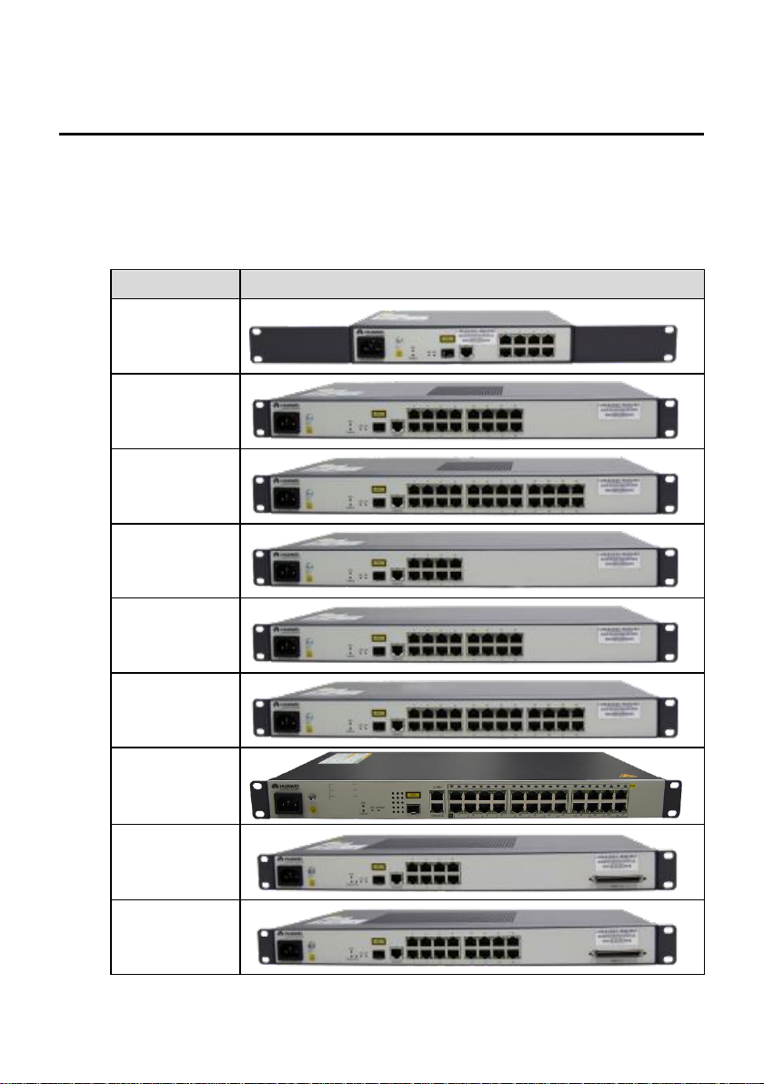
2 Appearance
Configuration
Appearances
MA5821 8FE
MA5821 16FE
MA5821 24FE
MA5821 8GE
MA5821 16GE
MA5821 24GE
MA5821 24GE,
PoE
MA5822
8FE+8POTS
MA5822
16FE+16POTS
The MA5821/MA5822 is a box-type device 1U (1U = 44.45mm) high. The appearances of devices
using different modes are different.
Table 2-1 shows the appearances of the MA5821/MA5822.
Table 2-1 MA5821/MA5822 appearances
Page 5
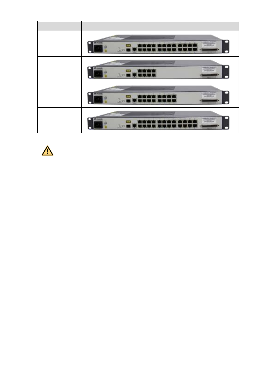
Configuration
Appearances
MA5822
24FE+24POTS
MA5822
8GE+8POTS
MA5822
16GE+16POTS
MA5822
24GE+24POTS
CAUTION
This is a Class A product. This product may cause radio interference, in which case the user
may be required to take practical precautions interference.
Page 6
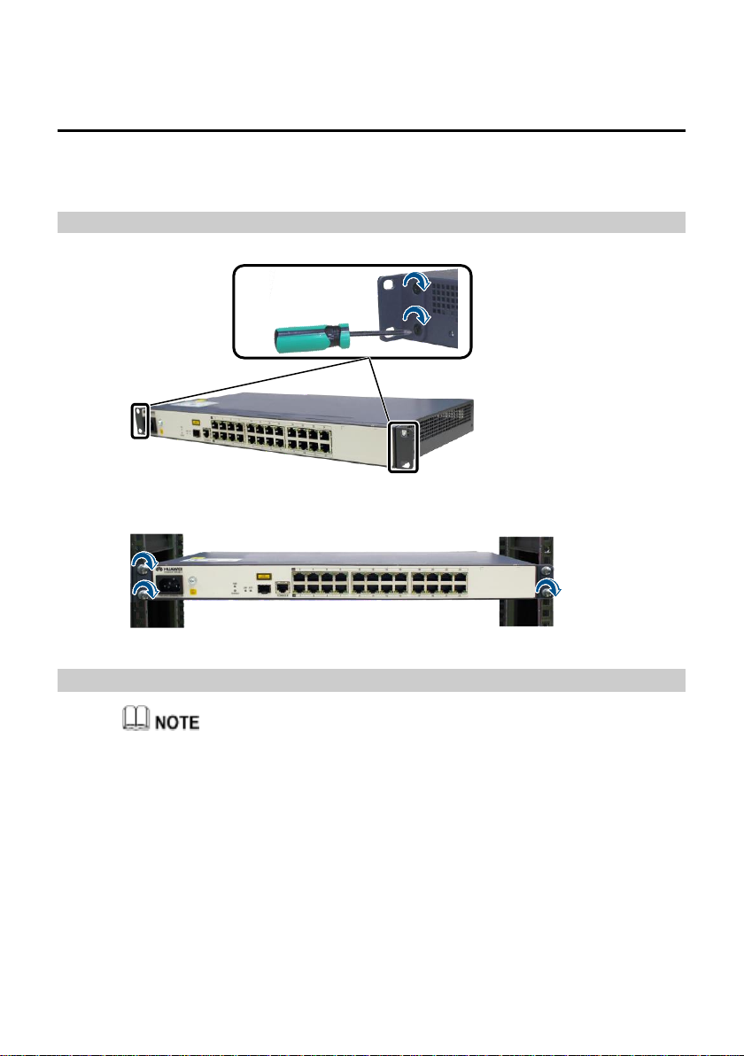
3 Installing the MA5821/MA5822
The configuration of MA5821/MA5822 can be installation in the 19-inch cabinet, chassis and
network cabinet.
Installation in the 19-inch cabinet
Step1
Install mounting ears
Step2
Install the chassis
Installation in the network cabinet
1. The air intake vent and the air exhaust vent of the network cabinet should keep expedite
for the MDU heat dissipation.
2. If the network cabinet is installed indoors or in a corridor that is out of rain, the network
cabinet must meet the requirements of IP31 class protection.(The first number "3" means
the solid particle with a diameter equal to or larger than 2.5 mm can be prevented from
entering the cabinet. The second number "1" means the drips fallen vertically cannot
damage the device. )
3. If the network cabinet is installed outdoors or in a corridor that is exposed to rain, the
network cabinet must meet the requirements of IP55 class protection. ( "IP" refers to
International Protection. The first number "5" refers to the class for preventing the solid
particle from entering the device. That is, the network cabinet cannot completely prevent
Page 7

dust from entering the device, but the amount of dust that enters the network cabinet does
1. MA5821/MA5822ontally installed (with
the panel facing the front)
2. MA5821/MA5822 vertically installed (with
the panel facing the front)
3. MA5821/MA5822 vertically installed
(with the panel facing downwards, fix the
rack-mounting ears on the side)
4. MA5821/MA5822 vertically installed
(with the panel facing the right, fix the rack-
mounting ears on the side)
CAUTION
>2 U
The side
>2 U
The GE electrical
port (above)
The optical port
(below)
not damage the device. The second number "5" refers to the class for preventing water
from entering the network cabinet. That is, the water sprayed from different directions
to the network cabinet does not damage the device. )
Don’t stack installation of the MA5821/MA5822.
The modes of installing the MDU in the network cabinet of the customer vary with the
specifications for the network cabinet of the customer. The following section describes the
common modes to be taken for installing the MDU in the natural heat dissipation network cabinet
(The network cabinet is without fan) of the customer. This can serve as a guide for hardware
engineers to install the MDU (fix the rack-mounting ears on the front, side or back).
Page 8

1. MA5821/MA5822
2. MDF
3. ODF
4. Grounding bat
5. AC lightning protection
bar
6. AC power distribution
cabinet
In the case of the TN-C-S and TN-S
AC power distribution systems, it is
recommended that you use the PE
wire of the AC power cable for the
MA5821/MA5822 grounding
connection. The prerequisite is that
the PE wire of the AC power cable
for the corridor of the building is
already grounded properly.
Use the ground cable (the cross-
sectional area of the ground cable
>100 mm
The side
>100 mm
The GE electrical
port (above)
The optical port
(below)
CAUTION
5
6
1
4
PE
N
L
TN-S power distribution system
L
PGND
N
5
6
L
TN-C-S power distribution system
1
4
L
PE
N
PGND
For better heat dissipation, avoid using the installation mode of placing the MDU vertically
(with the panel facing upwards) in the network cabinet.
Guide for grounding the network cabinet
Page 9

should be equal to or greater than 6
mm2) to connect the grounding bar
and all the internal devices, and the
grounding bar to the network
cabinet in an equipotential manner
through a metallic structure.
Connect the grounding point of the
reinforcing rib of the optical fiber to
the ground bar through a ground
cable, or connect this grounding
point to the network cabinet in an
equipotential manner through a
metallic structure.
1. MA5821/MA5822
2. MDF
3. ODF
4. Grounding bar
5. ACPDU
6. AC power
distribution cabinet
In the case of the TT power
distribution system, it is
MDF
ODF
2
3
4
5
LPEN
Power cable
6
TN-S power distribution system
1
CAUTION
6
L
N
TT power distribution system
1
5
4
PGND
1. The network cabinet must be grounded through an external ground cable (PGND
2. The network cabinet must be grounded through an external ground cable (PGND
3. A power cable with 3-5 m must be used for decoupling between the surge protector
cable).
cable).
and ONU power supply.
Page 10

recommended that an external
grounding device be adopted. For
example, use the dedicated
grounding device of the building
(such as the grounding flat steel
sheet, grounding stud, and
grounding bar) or the base steel bar
of the reinforcement concrete of the
building, or deploy a new earth
screen.
Use the ground cable (the cross-
sectional area of the ground cable
should be equal to or greater than 6
mm2) to connect the grounding bar
and all the internal devices, and the
grounding bar to the network
cabinet in an equipotential manner
through a metallic structure.
Connect the external ground cable
(PGND cable) of the network
cabinet to the external grounding
device. As specified by the national
grounding standard, the crosssectional area of the external
ground cable should be equal to or
greater than 16 mm2.
MDF
ODF
4
3
2
5
L
N
PGND cable
Power cable
6
TT power distribution system
1
Guide to ground the strength member
Engineering responsibilities
Page 11

Optical Cable
Provider
Engineeri
ng Party
Recommended Solution
Remarks
Huawei
Huawei
Solution 1 is preferred. If
solution 1 fails to
implement, Huawei is
required to communicate
with the customer about
engineering risks and sign
a memorandum with the
customer before using
solution 2.
If solution 1 is used, the
engineering quality must strictly
comply with engineering
specifications.
If solution 2 is used, the network
box must be securely grounded.
In addition, a metal protective
cover must be installed between
the fiber strength member and
network box fixing points,
preventing sparks from
spreading if the fiber strength
member connects to a heavycurrent power line.
Customer
Solution 1
If the engineering does not
comply with solution 1, the
customer must take
consequences.
Customer
Huawei
Requirements: During
engineering, do not route
the fiber strength member
into the network box. In
addition, ground the fiber
strength member and the
network box separately.
Install the network box
and MxU based on the
instructions provided in
this document.
The customer must ensure that
the fiber strength member is not
be routed inside the network
box. Otherwise, the customer
must take consequences.
Customer
Grounding solution 1: The fiber strength member is isolated from the network box and grounded
outside the network box.
This solution prevents the introduction of sudden heavy currents into the network box, thereby
protecting the device inside the network box against heavy currents. (A long-distance armored
optical cable may introduce sudden heavy currents into the network box if the outer insulation
layer is broken and connects to a heavy-current power line.) Solution 1 is implemented as
follows:
1. Strip the outer insulation layer and armored tube from the fiber strength member at the
ground point. Then, clean bare optical fibers and use a protection tube to protect them. (Use
outdoor tubes in outdoor scenarios and common tubes in indoor or corridor scenarios. Use
Page 12

waterproof tape produced by 3M or COTRAN.)
During onsite operations,
ensure that optical fibers
are force-free and the bend
radius is greater than 40
mm. Otherwise, services
may become abnormal or
even fail due to degraded
signal transmission.
The fiber strength member
must be securely grounded.
In addition, the ground
point of the fiber strength
member must be at least 3
meters above the ground
(which prevents manual
touching), and no
combustible materials are
around the ground point
within a distance of 0.3 m.
If the fiber strength
member fails to be securely
grounded, it must be
insulated. Otherwise, the
fiber strength member may
introduce heavy currents if
it connects to a heavycurrent power line,
threatening human safety.
Network box
ODF
MDU
220 V AC
Power cable
Fiber strength member
Optical fiber
Exterior wall
Waterproof tape
Sleeve
Ground bar
Strong-current discharge path
> 3 m
Fiber protection tube
5 mm
Sandpaper
Optical cable
Metal armored layer
Fiber strength member
Loose tube
Fiber
CAUTION
2. Use a piece of sandpaper to polish burrs at the stripped position of the optical cable. Then,
use insulation tape to wrap the stripped optical cable. When wrapping the waterproof tape,
ensure that fiber cores are force-free.
3. Cut excess fiber strength member for grounding.
Grounding solution 2: The fiber strength member is grounded inside a network box.
The fiber strength member must be connected to a ground bar at the ground point using a ground
cable. The ground point can connect to the network box using a metal in an equipotential manner.
When the fiber strength member connects to a heavy-current power line, heavy currents may be
discharged inside the network box using the ground bar. If this happens, sparks may occur at the
contact point between the fiber strength member and the ground bar, which may burn the device
and the network box. To prevent this issue from occurring, use solution .
Page 13

If the ground bar of the
network cabinet fails to
securely ground, ensure
that the fiber strength
member is disconnected
from the ground bar and
that the fiber strength
member is properly
insulated. Otherwise,
heavy currents may be
discharged using the
network ports on the local
and peer devices, which
may damage these
network ports.
Strong-current discharge path
Network box
ODF
MDU
220 V AC
Power cable
Ground bar
Fiber strength member
Optical
fiber
CAUTION
Shield crystal head
Network cable
Optical fiber
AC power cable
PGND cable
POTS subscriber cable
CAUTION
Routing cables
Step1
Routing PGND cable and power cable
4 Routing cables
Correct ground cable connection ensures surge and interference protection. Therefore,
ensure that the device connects to the ground properly. If the device does not connect to the
ground properly, the device may be damaged due to lightning strikes, services carried on the
device may become abnormal, and even personal safety is threatened.
Page 14

To the grounding point of the cabinet
PGND cable
AC power cable
To AC power socket
OT6-4
Network cable
To subscriber device
CAUTION
Step2
Routing network cable
Network cables cannot be directly used to connect FE or GE ports between the
MA5821 and MA5822.
If they are directly connected, FE or GE ports will be deactivate when the ring check
function is enabled.
If FE or GE ports are deactivated, perform the following to activate them:
1. Run the
display ring check record
command to query whether a ring network is
formed on ports.
2. Disconnect the network cable if a ring network is formed on ports.
3. Run the
undo shutdown
resume-interval
command to set the automatic port activation time to activate the port.
command to activate the port or run the
ring check
Step3
Routing POTS cable (Only MA5822 support)
Page 15

POTS subscriber cable
To MDF
Step4
(Optional) Route the GE splitter cable.
When the MA5822 needs to be used with the GE splitter, connect the cable as shown
in the following figure.
On the device side, cores of the POTS cable need to be crimpted by using the RJ11
connector.
Page 16

Step5
Indicator
Description
PWR: power supply
status indicator
Green on
The device is powered on.
Green off
The device is powered
off.
RUN/ALARM:
running status
indicator
Red blinking 0.25s on and
0.25s off
The device is starting up.
green blinking 1s on and 1s
off
The device is functioning
properly.
Green on
The device is faulty.
Optical fiber To ODF Spiral tube
PWR
RUN/ALM
AUTH
LINK
POTS
Routing optical fiber
5 Description of LEDs
The MA5821/MA5822 provides a variety of indicators on its panel to help users learn about
the running status of the device.
Table 5-1 Indicators on the MA5821/MA5822
Table 5-1 describes the indicators on the MA5821/MA5822
Page 17

Indicator
Description
LINK: uplink status
indicator
Green on
The optical port is
receiving optical signal.
green blinking 0.25s on and
0.25s off
The optical port is
working in continuous
mode.
Green off
The optical port is not
receiving optical signal or
no connection is set up.
AUTH: Certification
indicator
green blinking 0.25s on and
0.25s off
The device is registering.
green blinking 1s on and 1s
off
When the LINK and
AUTH lights at the same
time the green blinking
1s on and 1s off ,
indicating that the
MA5821/MA5822
device is a rogue ONU
state.
The mode being used on
the port is incorrect.
Green on
The optical port has
successfully registered
with the upper layer
device.
Green off
No optical fiber is
connected to the device/
GE: Electrical
interface status
indicator
Green on
A connection is set up on
the port.
Green off
No connection is set up
on the port.
Yellow on
The port is transmitting or
receiving data.
Yellow off
No data is transmitted or
received on the port.
Indicators of the
POTS port (only the
MA5822 supports
this port and LED)
Green: on
A minimum of one
service port is busy.
Green: off
All the ports are idle.
PoE: Ethernet power
Green: on
Power over Ethernet is
power on.
Page 18

Indicator
Description
status indicator(only
the MA5821 24GE
POE supports this
port and LED)
Green: off
Power over Ethernet is
power off.
 Loading...