

Page 1

IPC6061-FP
V300R019C00
Quick Start Guide
Issue 01
Date 2019-02-22
HUAWEI TECHNOLOGIES CO., LTD.
Page 2

Copyright © Huawei Technologies Co., Ltd. 2019. All rights reserved.
No part of this document may be reproduced or transmitted in any form or by any means without prior written
consent of Huawei Technologies Co., Ltd.
Trademarks and Permissions
and other Huawei trademarks are trademarks of Huawei Technologies Co., Ltd.
All other trademarks and trade names mentioned in this document are the property of their respective
holders.
Notice
The purchased products, services and features are stipulated by the contract made between Huawei and the
customer. All or part of the products, services and features described in this document may not be within the
purchase scope or the usage scope. Unless otherwise specified in the contract, all statements, information,
and recommendations in this document are provided "AS IS" without warranties, guarantees or
representations of any kind, either express or implied.
The information in this document is subject to change without notice. Every effort has been made in the
preparation of this document to ensure accuracy of the contents, but all statements, information, and
recommendations in this document do not constitute a warranty of any kind, express or implied.
Huawei Technologies Co., Ltd.
Address: Huawei Industrial Base
Bantian, Longgang
Shenzhen 518129
People's Republic of China
Website: http://e.huawei.com
Issue 01 (2019-02-22) Copyright © Huawei Technologies Co., Ltd. i
Page 3

IPC6061-FP
Quick Start Guide Contents
Contents
1 Important Safeguards and Warnings.........................................................................................1
2 Unpacking Inspection...................................................................................................................5
3 Device Framework.........................................................................................................................6
3.1 Structure and dimension................................................................................................................................................. 6
3.2 Dimensions..................................................................................................................................................................... 9
4 Installation.................................................................................................................................... 10
4.1 (Optional) Install the SD Card......................................................................................................................................10
4.2 Fix Device.....................................................................................................................................................................11
4.3 Connect Device Cables.................................................................................................................................................14
5 Network Configuration..............................................................................................................17
5.1 Set the Initial Password................................................................................................................................................ 17
5.2 Modify IP Address........................................................................................................................................................19
5.3 Login Web Interface..................................................................................................................................................... 20
6 Warranty Card.............................................................................................................................. 21
Issue 01 (2019-02-22) Copyright © Huawei Technologies Co., Ltd. ii
Page 4

IPC6061-FP
Quick Start Guide
1 Important Safeguards and Warnings
1 Important Safeguards and Warnings
The following describes the instructions for using the device. To prevent crisis and asset
losses, carefully read the instructions before using the device and strictly comply with the
instructions during device usage. Please keep this user manual well for future reference.
FCC SDOC Compliance Statement
Supplier's Declaration of Conformity (SDoC)
Unique Identifier: trade name: HUAWEI; product name: Network camera; model number:
IPC6061-FP
Responsible Party- U.S. Contact Information
Huawei Technologies USA Inc.
5700 Tennyson Parkway, Suite 500
Plano, Texas 75024
Main: 214-919-6000 / TAC Hotline: 877-448-2934
FCC Compliance Statement ( for products subject to Part 15)
This device complies with part 15 of the FCC Rules. Operation is subject to the following two
conditions: (1) This device may not cause harmful interference, and (2) this device must
accept any interference received, including interference that may cause undesired operation.
Symbol Conventions
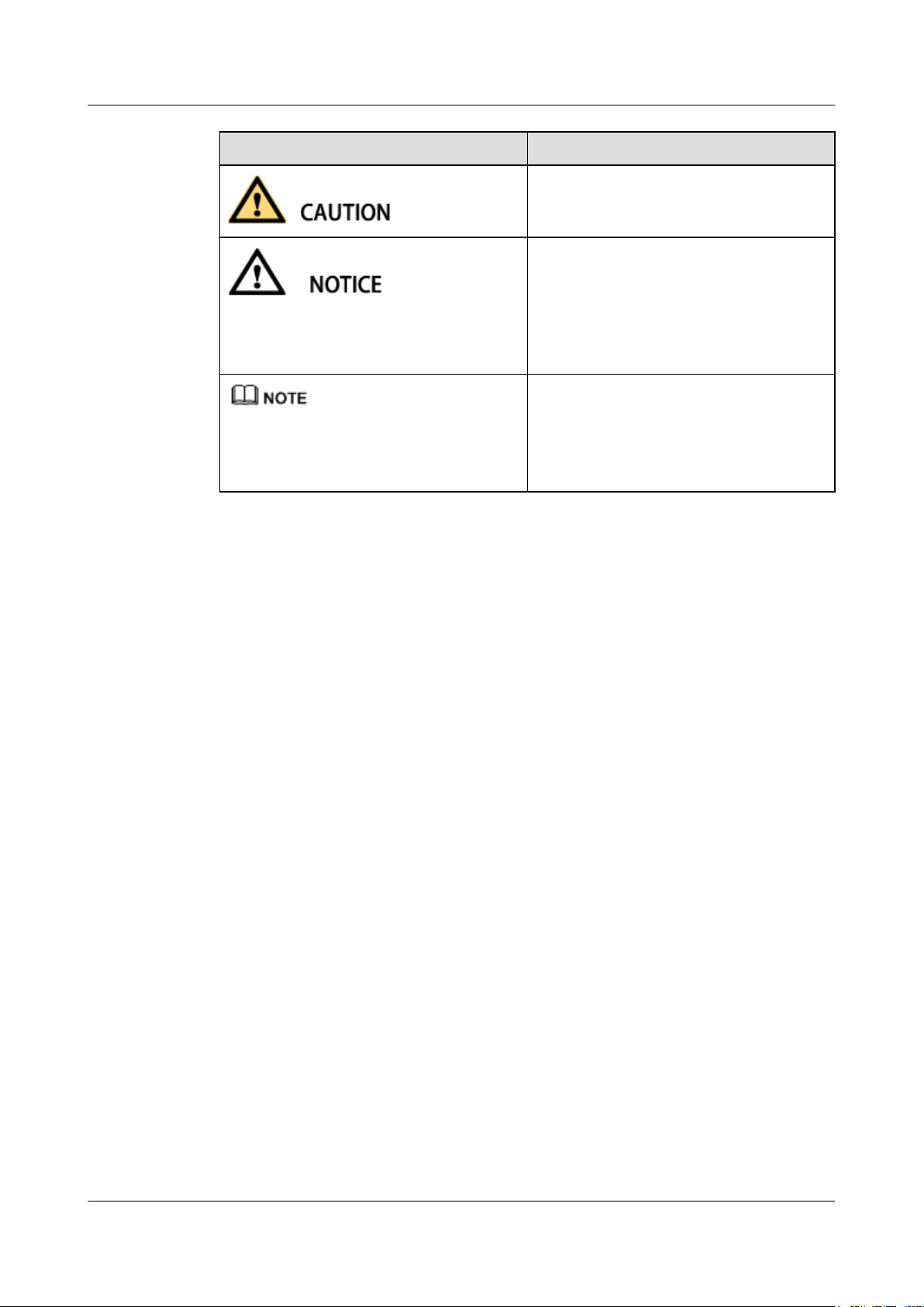
The symbols that may be found in this document are defined as follows:
Symbol
Issue 01 (2019-02-22) Copyright © Huawei Technologies Co., Ltd. 1
Description
Indicates an imminently hazardous situation
which, if not avoided, will result in death or
serious injury.
Indicates a potentially hazardous situation
which, if not avoided, could result in death
or serious injury.
Page 5
IPC6061-FP
Quick Start Guide
1 Important Safeguards and Warnings
Symbol Description
Indicates a potentially hazardous situation
which, if not avoided, may result in minor
or moderate injury.
Indicates a potentially hazardous situation
which, if not avoided, could result in
equipment damage, data loss, performance
deterioration, or unanticipated results.
NOTICE is used to address practices not
related to personal injury.
Calls attention to important information,
best practices and tips.
NOTE is used to address information not
related to personal injury, equipment
damage, and environment deterioration.
Electrical safety
l All installation and operation should conform to your local electrical safety codes.
l Make sure the power supply is correct before operating the device.
l The power source shall conform to the requirement of the Safety Extra Low Voltage
l A readily accessible disconnect device shall be incorporated in the building installation
l Prevent the power cable from being trampled or pressed, especially the plug, power
Environment
l Do not aim the device at strong light to focus, such as lamp light and sun light, otherwise
l Transport, use and store the device within the range of allowed humidity and
l Do not place the device in a damp or dusty environment, extremely hot or cold
(SELV) standard, and supply power with rated voltage which conforms to Limited power
Source requirement according IEC60950-1. Please note that the power supply
requirement is subject to the device label.
wiring.
socket and the junction extruded from the device.
it might cause over brightness or light marks, which are not the device malfunction, and
affect the longevity of Charge Coupled Device (CCD) or Complementary Metal-Oxide
Semiconductor (CMOS).
temperature.
temperatures, or the locations with strong electromagnetic radiation or unstable lighting.
l Keep the camera away from water or other liquid to avoid damages to the internal
components.
l Keep the indoor device away from rain or damp to avoid fire or lightning.
l Keep sound ventilation to avoid heat accumulation.
l Pack the device with standard factory packaging or the equivalent material when
transporting the device.
Issue 01 (2019-02-22) Copyright © Huawei Technologies Co., Ltd. 2
Page 6

IPC6061-FP
Quick Start Guide
l Heavy stress, violent vibration or water splash are not allowed during transportation,
storage and installation.
l The device needs to be installed in the location where professional staff can cover
(professionals need to know the attentions of using the device), non-professionals are not
allowed to enter device installation area when the device is operating normally, which
may cause accidental damage.
l Ensure the network link quality during project construction and device installation.
l When a camera is installed near the seaside or salt water lake, ensure that the camera is
more than 10 km away from the coastline and lake shoreline.
Operation and Daily Maintenance
l Do not directly touch the heat dissipation component of the device to avoid scald.
l Do not dismantle the device because there is no component that can be fixed by users
themselves. Otherwise, it might cause water leakage or bad image due to unprofessional
dismantling. Please contact after-sale service to replace desiccant when it becomes green.
(The desiccant is not provided by default)
l It is advised to use the device together with lightning arrester to improve lightning
protection effect.
l It is advised to get the grounding holes to be grounded to enhance the reliability of the
device.
l Do not directly touch the optic component CCD or CMOS. You can use the air blower to
blow away the dust or dirt on the lens surface. Please use a dry cloth wetted by alcohol to
wipe away the dust gently if necessary.
l Use the dry soft cloth to clean the device. If the dust is difficult to be removed, please
wipe it away with a clean cloth wetted slightly by the mild detergent, and then use the
dry cloth to clean the device. Do not use volatile solvents like alcohol, benzene, thinner,
or strong detergent with abrasiveness, otherwise it will damage the surface coating or
reduce the working performance of the device.
l The IPC shield is a kind of optical component, please do not touch or wipe the shield
surface during installation and application, it may stain dust, grease or fingerprint, you
can use absorbent cotton to dip some diethyl ether or use soft cloth to dip some water
and then wipe gently. You can also use air gun to remove the dust if the shield is stained
with dust.
1 Important Safeguards and Warnings
Issue 01 (2019-02-22) Copyright © Huawei Technologies Co., Ltd. 3
Page 7

IPC6061-FP
Quick Start Guide
1 Important Safeguards and Warnings
l Please strengthen the protection of network, device data and personal information, adopt
necessary measures of guarantee device network security, including but not limited to
using strong password, modifying password regularly, upgrading firmware to the latest
version, isolating computer network and so on. For the IP camera firmware of some old
version, the ONVIF password will not be modified automatically after the main password
of the system is modified. You need to upgrade the camera firmware or upgrade the
ONVIF password manually. Please modify the default password after login to avoid being
stolen. For details about how to change the ONVIF password, see ONVIF User in the User
Manual.
l Use the standard components provided by manufacturer and make sure the device is
installed and fixed by professional engineers.
l The surface of the image sensor should not be exposed to laser beam radiation in an
environment where a laser beam device is used.
l Do not provide two or more power supply sources for the device; otherwise it might
damage the device.
Disclaimer
l This manual is for reference only. Please refer to the actual product for more details.
l Minor differences might be found in user interface, and there might be deviation between
the actual value of some data and the value provided in the manual due to the reasons
such as the real environment is not stable. Please refer to the final explanation of the
company if there is any doubt or dispute.
l The company is not liable for any loss caused by the operation that does not comply with
the manual.
l Please contact the supplier or customer service if there is any problem occurred when
using the device.
l If the obtained PDF file cannot be opened, upgrade the reading tool to the latest version
or use another mainstream reading tool.
l All the designs and software are subject to change without prior written notice. The
manual will be regularly updated according to the product upgrade without prior
announcement.
l If there is any uncertainty or controversy, please refer to our final explanation.
Issue 01 (2019-02-22) Copyright © Huawei Technologies Co., Ltd. 4
Page 8

IPC6061-FP
Quick Start Guide
2 Unpacking Inspection
2 Unpacking Inspection
Before installation, open the package and check whether all the accessories are included. For
details, see the accessory list delivered with the device. For details about the configuration,
see the specific product documentation.
Issue 01 (2019-02-22) Copyright © Huawei Technologies Co., Ltd. 5
Page 9

IPC6061-FP
Quick Start Guide
3 Device Framework
3 Device Framework
3.1 Structure and dimension
3.2 Dimensions
3.1 Structure and dimension
NOTE
l The following structure figure is for reference only. It is only used to understand the functions of
device external ports.
l There might be some minor differences between different devices, so please refer to the actual
products you purchased.
Issue 01 (2019-02-22) Copyright © Huawei Technologies Co., Ltd. 6
Page 10
IPC6061-FP
Quick Start Guide
3 Device Framework
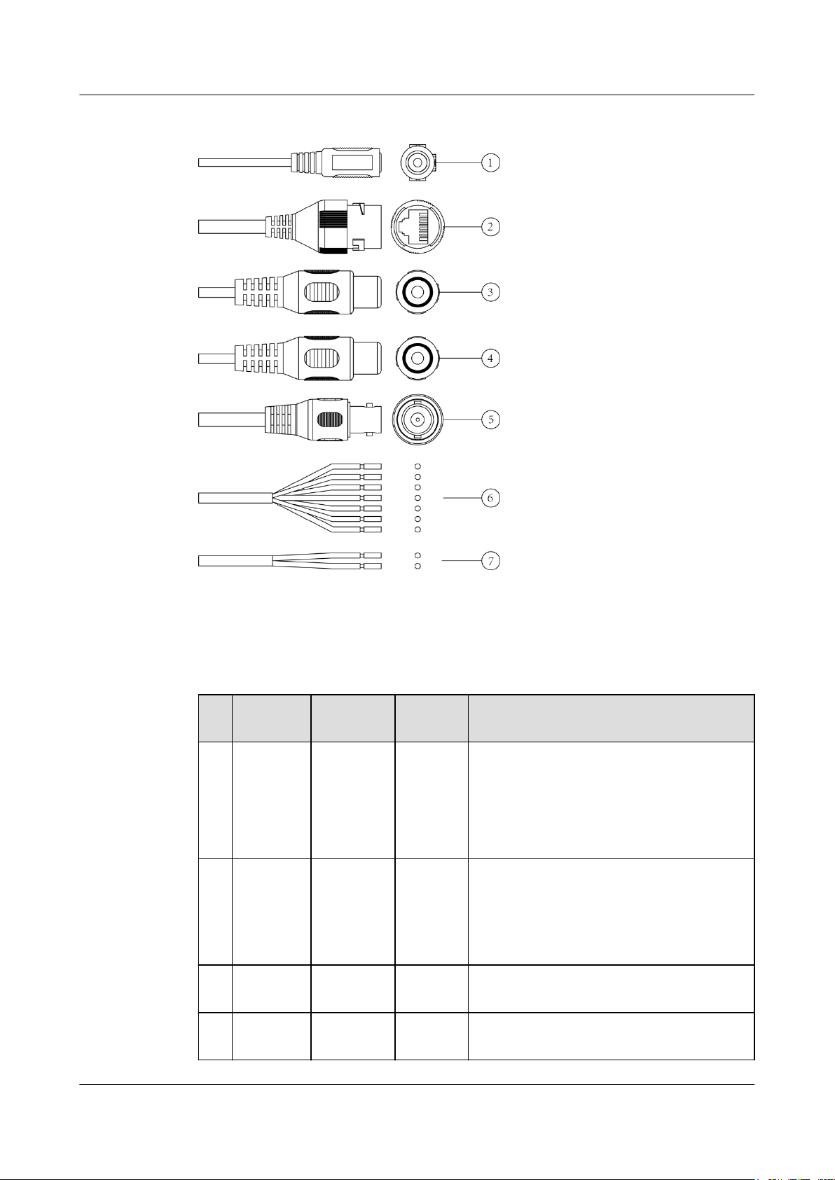
Figure 3-1 External ports
Please refer to Table 3-1 and Table 3-2 for more details about external port functions and I/O
port functions.
Table 3-1 External port functions
N
Port Port name ConnectorFunction description
o.
1 Power Power
input
port
2 LAN Network
port
- Connects to 12 V DC power. Please be sure
to power the device according to the label
instruction.
NOTE
It may cause damage to the device if it fails to
power the device according to label instruction.
Ethernet
port
Connects to the standard Ethernet cable and
provides
PoE power supply.
NOTE
Some devices do not support PoE power supply.
3 AUDIO
IN
Audio
input port
RCA Receives analog audio signal from pickup
and so on.
4 AUDIO
OUT
Issue 01 (2019-02-22) Copyright © Huawei Technologies Co., Ltd. 7
Audio
output port
RCA Outputs audio signal to speaker and some
other devices.
Page 11

IPC6061-FP
Quick Start Guide
3 Device Framework
No.Port Port name ConnectorFunction description
5 VIDEO
OUT
Video
output port
BNC
l Outputs analog video signals: supports
connection to a TV monitor to view
images.
l Outputs HDCVI signals: supports DVR
image viewing through HDCVI.
6 I/O I/O port - Includes alarm input and output. Refer to
Table 3-2 for more details.
7 RS485 RS-485
- Controls the external PTZ device.
port
Table 3-2 I/O port functions
Port name
Cable
Cable port name Function description
sequence
I/O port 1 ALARM_OUT1 Alarm output port 1,
outputs alarm signal to
2 ALM_OUT_GND1
alarm device.
NOTE
ALARM_OUT1 can only be
used with
ALM_OUT_GND1
cooperatively when
connecting to alarm device.
3 ALARM_IN1 Alarm input port 1,
receives on-off signal of
external alarm source.
4 ALARM_IN2 Alarm input port 2,
receives on-off signal from
external alarm source.
5 ALM_IN_GND Alarm input GND
terminal.
6 ALARM_OUT2 Alarm output port 2,
outputs alarm signal to
7 ALM_OUT_GND2
alarm device.
NOTE
ALARM_OUT2 can only be
used with
ALM_OUT_GND2
cooperatively when
connecting alarm device.
Issue 01 (2019-02-22) Copyright © Huawei Technologies Co., Ltd. 8
Page 12
IPC6061-FP
Quick Start Guide
3.2 Dimensions
NOTE
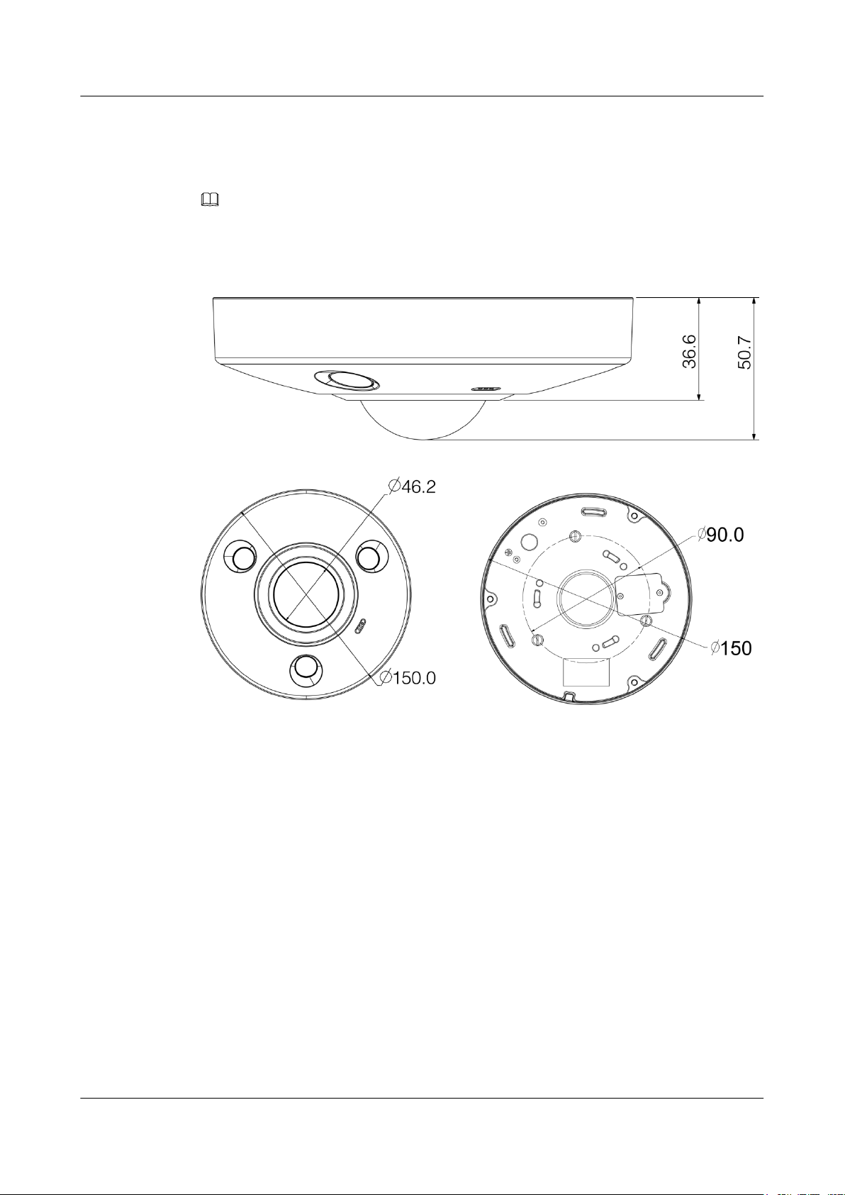
The side dimensions of the device are 36.6 mm x 50.7 mm, as shown in Figure 3-2. Refer to the actual
product model for more details.
Figure 3-2 Device dimensions (unit: mm)
3 Device Framework
Issue 01 (2019-02-22) Copyright © Huawei Technologies Co., Ltd. 9
Page 13

IPC6061-FP
Quick Start Guide
4 Installation
4 Installation
4.1 (Optional) Install the SD Card
4.2 Fix Device
4.3 Connect Device Cables
4.1 (Optional) Install the SD Card
NOTE
l It needs to implement the step when the device is equipped with a Micro SD card slot and it needs to
use Micro SD card.
l Power off the device before installing an SD card.
l The Micro SD card cover is related to the device waterproof performance. Please be sure to put the
silica gel ring of the SD card cover back to the waterproof groove after the Micro SD card is
installation completely.
l The Micro SD card shall be replaced within 4 hours; otherwise it will cause desiccant failure and
abnormalities such as water mist.
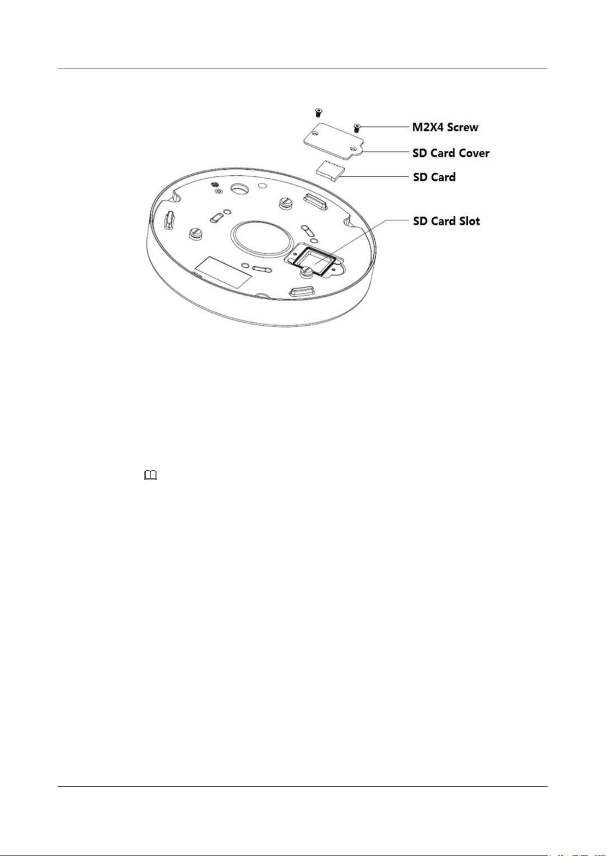
Step 1 Find SD card slot in the location which is shown in Figure 4-1, use a Phillips screwdriver to
take down the screws on the cover of SD card.
Issue 01 (2019-02-22) Copyright © Huawei Technologies Co., Ltd. 10
Page 14
IPC6061-FP
Quick Start Guide
4 Installation
Figure 4-1 SD card installation diagram
Step 2 Adjust the direction of SD card, insert it into the slot and install the SD card properly.
Step 3 Tighten back the screws on the SD card cover.
----End
4.2 Fix Device
NOTE
The device mounting device needs to sustain at least 3X weight of bracket and camera.
Network camera can be directly placed on the desktop for monitoring, it can also use bracket
to install the device on the ceiling, which means there are three types of installation modes
which are ground mount, ceiling mount and wall mount. The following chapter is an example
of ceiling mount.
Before you complete the installation and debugging, do not remove the electrostatic attraction
film on the transparent enclosure. Otherwise it may result in injury. After removing the
electrostatic attraction film, do not touch dome enclosure in case it may leave stain.
Issue 01 (2019-02-22) Copyright © Huawei Technologies Co., Ltd. 11
Page 15
IPC6061-FP
Quick Start Guide
4 Installation
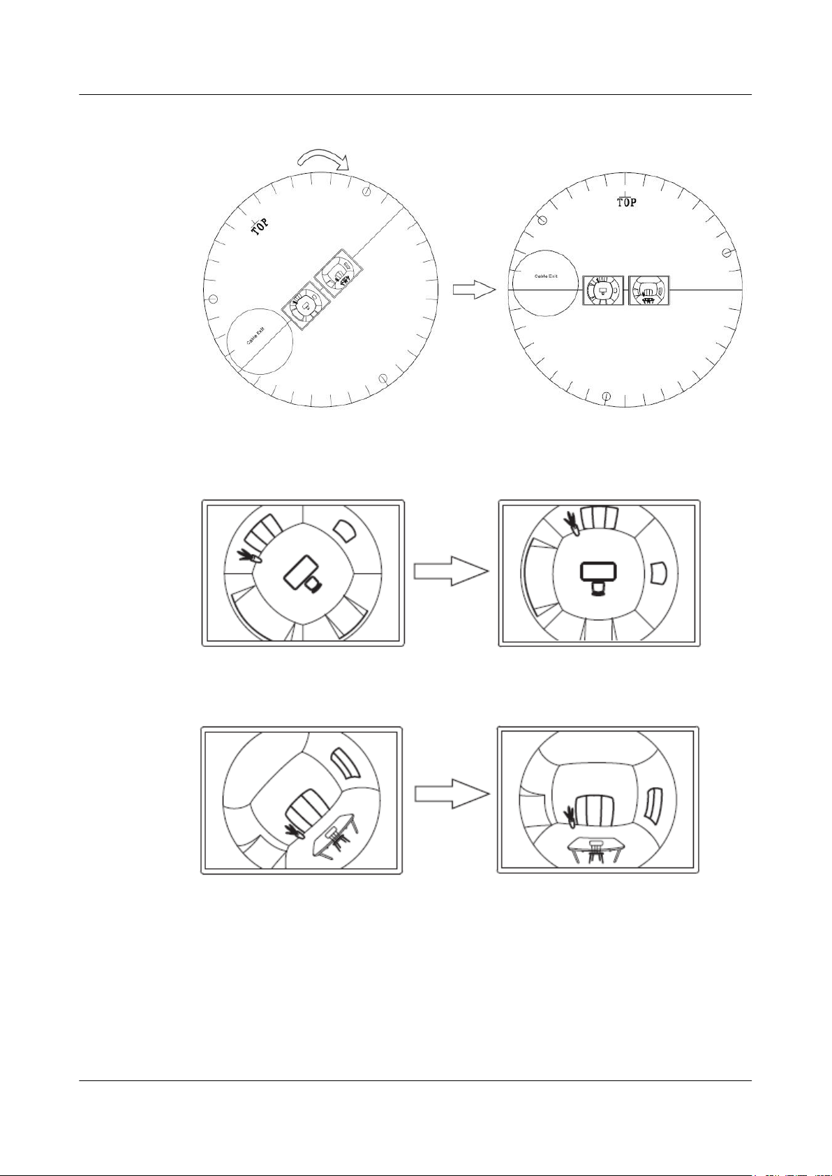
Figure 4-2 Installation Position Map
Figure 4-3 Ceiling Mount Effect
Figure 4-4 Wall Mount Effect
Issue 01 (2019-02-22) Copyright © Huawei Technologies Co., Ltd. 12
Page 16
IPC6061-FP
Quick Start Guide
4 Installation
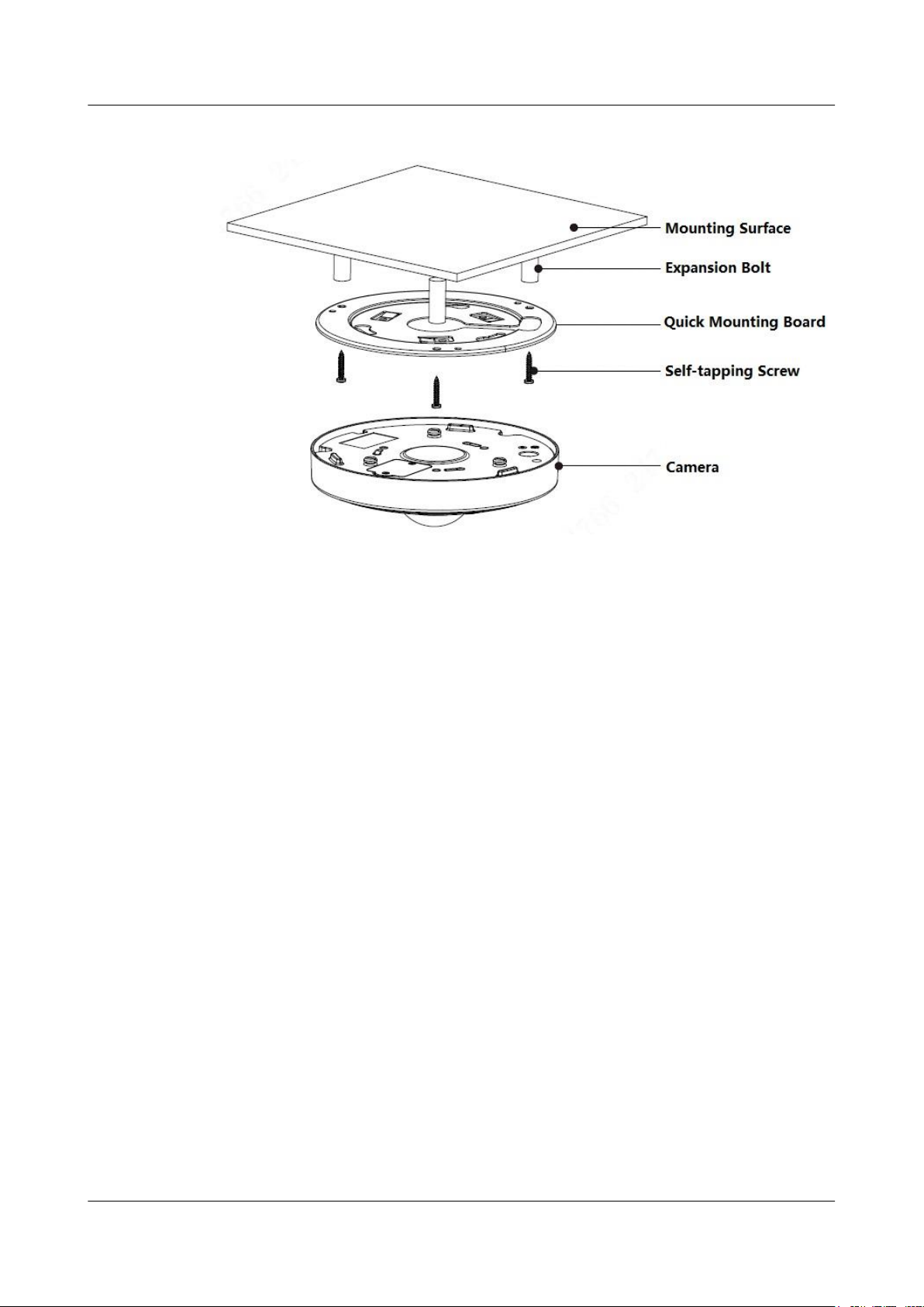
Figure 4-5 Device installation diagram
Step 1 Take out the installation position map (shown in Figure 4-2) from the accessories bag, adjust
the installation angle of the installation position map according to the needed monitoring
angle, and then paste it on the installation surface such as ceiling or wall and so on.
Step 2 Please dig three bottom holes on the installation surface according to the location shown in
the installation position map. It needs to dig a cable exit hole whose diameter is no less than
28 mm on the installation surface according to the location on the installation position map if
the device adopts cable wiring from the top, which makes the cable go through.
Step 3 Insert 3 expansion bolts from the accessories bag into the bottom holes and lock them firmly,
adjust the position of device installation pedestal and pull the cable through the cable exit hole
on the installation surface.
Step 4 Align 3 fixed holes of screw on the bracket with 3 plastic expansion bolt fixed holes on the
installation surface, then tighten 3 ST3 self-tapping screws into 3 plastic expansion bolts and
fasten them firmly, fix the installation chassis on the installation surface.
Step 5 When installing dome body, find the little gap on the dome body and make it align with the
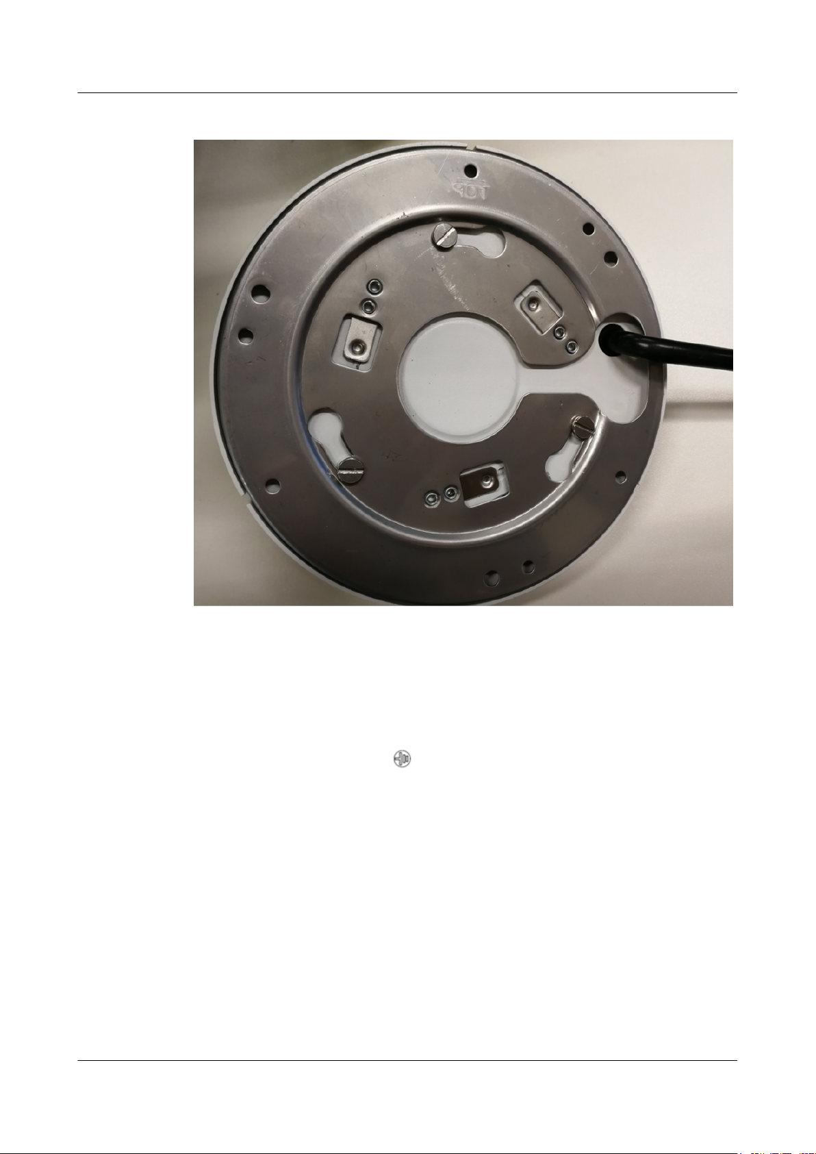
"TOP" direction on the installation chassis, rotate the dome body in clockwise direction and
secure it firmly. So far, installation is completed, as shown in Figure 4-6.
Issue 01 (2019-02-22) Copyright © Huawei Technologies Co., Ltd. 13
Page 17
IPC6061-FP
Quick Start Guide
4 Installation
Figure 4-6 Assembling the dome body and the quick mounting board
----End
4.3 Connect Device Cables
l Connect device corresponding power and audio cable well according to requirement, and
then use insulated tape to twine the connection respectively to make it waterproof.
l Connect the grounding hole ( ) to ground wire, which can improve device reliability
efficiently. The grounding hole is located next to the cable exit on the back of bottom
cover; the specification of ground screw is M2.5.
l Connect alarm input and output terminal to external cable according to Connect the
Alarm Input / Output Port, and use insulated tape to twine connection to make it
waterproof.
l Connect network cable to corresponding network port of the device cable according to
(Optional) Install the Waterproof Connector.
Connect the Alarm Input / Output Port
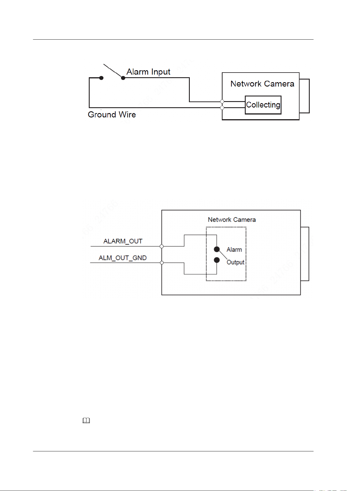
Step 1 Connect alarm input device to the alarm input of I/O port.
When the input signal is idle or grounded, the device can collect the different statuses of the
alarm input port. When the input signal is connected to 3.3 V or it is idle, the device collects
the logic "1". When the input signal is grounded, the device collects the logic "0".
Issue 01 (2019-02-22) Copyright © Huawei Technologies Co., Ltd. 14
Page 18
IPC6061-FP
Quick Start Guide
Step 2 Connect alarm output device to the alarm output port of I/O port cable.
4 Installation
Figure 4-7 Alarm input
Alarm output is relay switch output; alarm output port can only be connected to NO alarm
device. Port ALARM_OUT and ALM_OUT_GND form a switch, which is shown in Figure
4-8, the switch is used to provide alarm output. Generally the switch is opened; the switch
will be closed when there is alarm output.
Figure 4-8 Alarm output
Step 3 Log in Web interface, make corresponding settings upon alarm input and output on the
interface of alarm setup.
l Alarm input of Web is corresponding to the alarm input of I/O port cable. It is to set
corresponding NO, NC input according to the high and low level signal generated when
alarm happens for alarm input device.
l Set alarm output on the Web, alarm output is corresponding to the alarm output end,
which is the alarm output port of the I/O port cable.
----End
(Optional) Install the Waterproof Connector
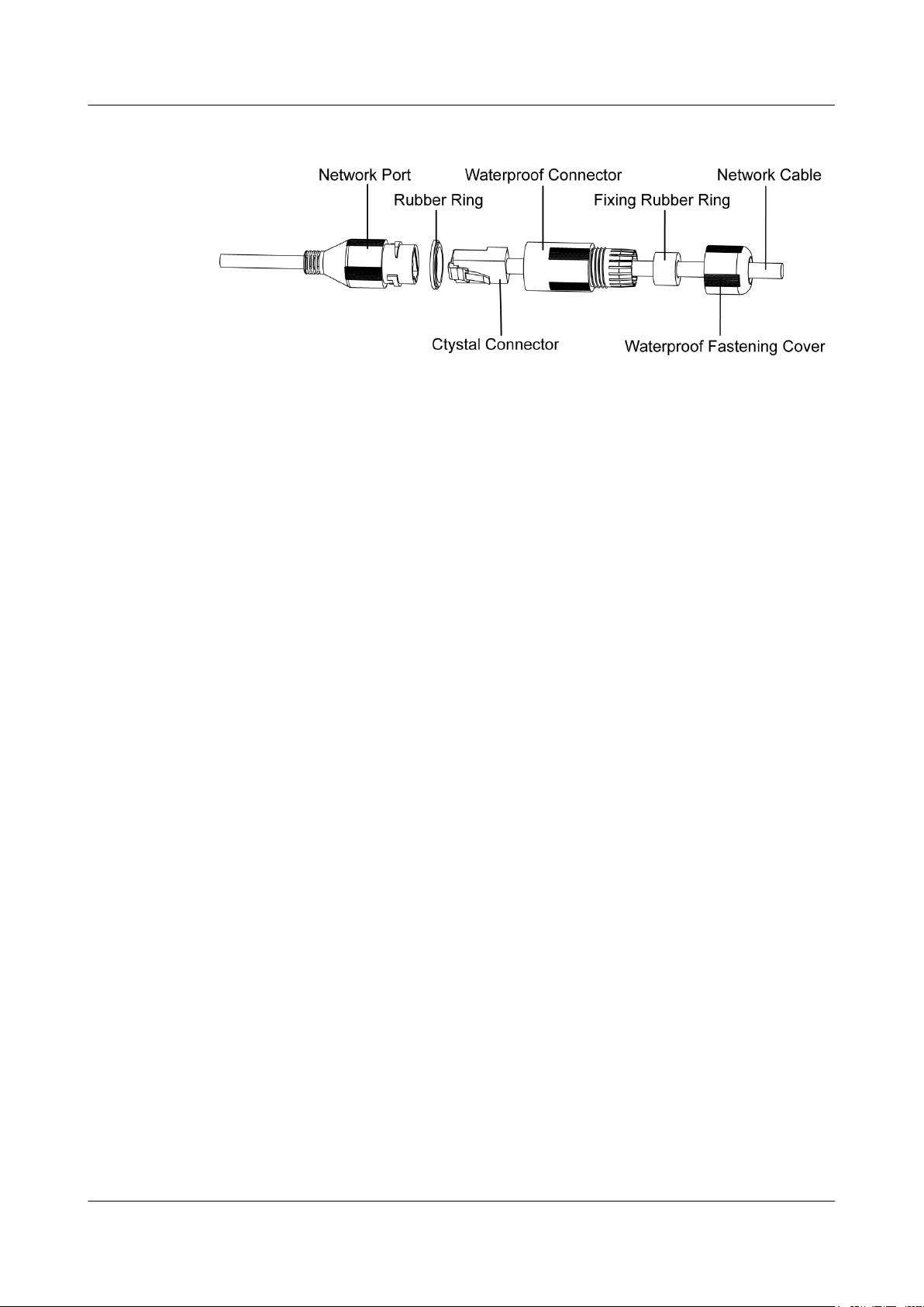
The installation process of waterproof connector for network port is shown in Figure 4-9.
NOTE
It needs to implement the operation when the device is equipped with waterproof connector and it is
used outdoors.
Issue 01 (2019-02-22) Copyright © Huawei Technologies Co., Ltd. 15
Page 19
IPC6061-FP
Quick Start Guide
Step 1 Keep the convex groove outward and install the rubber ring into the network port, keep the
Step 2 Pull the network cable without crystal head through main body of waterproof connector,
4 Installation
Figure 4-9 Waterproof connector installation
smaller hole of the rubber ring outward and install the fixing rubber ring into the main body
of the waterproof connector.
fixing rubber ring and waterproof locking cover, make the crystal head of network cable, and
then insert it into the network cable.
Step 3 Put the main body of waterproof connector on the network port and rotate it clockwise to lock
the network port and waterproof connector firmly.
Step 4 Put the waterproof locking cover on the main body of waterproof connector and rotate it
clockwise to lock the waterproof connector and waterproof locking cover firmly.
----End
Issue 01 (2019-02-22) Copyright © Huawei Technologies Co., Ltd. 16
Page 20

IPC6061-FP
Quick Start Guide
5 Network Configuration
5 Network Configuration
You can initialize device and modify IP address on the Web interface. Please refer to the User
Manual in the disk for more details.
NOTE
l It needs to set the initial password if it is the first time use device or the device is restored to factory
default.
l It can access the camera web page only when the device IP address (192.168.0.120 by default) and
the IP address of PC are in the same network segment.
l In order to make the camera have access to network smoothly, please plan available IP segment
according to the actual network environment.
l The following figures are for reference only; different models may have different interfaces.
5.1 Set the Initial Password
5.2 Modify IP Address
5.3 Login Web Interface
5.1 Set the Initial Password
Step 1 In the address box of Internet Explorer, enter http://IPC IP address and press Enter.
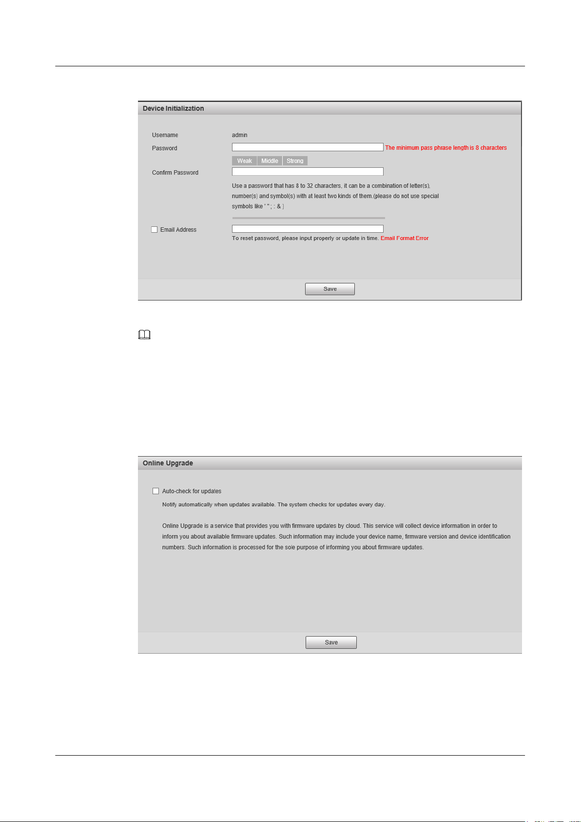
The Device Initialization page is displayed, as shown in Figure 5-1.
NOTE
192.168.0.120 is the default IP address of the camera.
Issue 01 (2019-02-22) Copyright © Huawei Technologies Co., Ltd. 17
Page 21
IPC6061-FP
Quick Start Guide
Step 2 Enter the new and confirm passwords and deselect Email Address.
5 Network Configuration
Figure 5-1 Device initialization
NOTE
The password can be set as 8 to 32 characters; it can be a combination of number(s), letter(s) and
symbol(s) with at least two kinds of them (excluding "'",""",";",":","&"). Please set password with high
security according to the password strong and weak prompt.
Step 3 Click OK.
The Online Upgrade page is displayed, as shown in Figure 5-2.
Figure 5-2 Online Upgrade
Step 4 Deselect Auto-check for updates.
Step 5 Click OK to complete device initialization.
----End
Issue 01 (2019-02-22) Copyright © Huawei Technologies Co., Ltd. 18
Page 22
IPC6061-FP
Quick Start Guide
5.2 Modify IP Address
Step 1 In the address box of Internet Explorer, enter http://IPC IP address and press Enter.
NOTE
192.168.0.120 is the default IP address of the camera.
Step 2 Enter the default user name and password.
The default user name is admin. The default password is the one set in 5.1 Set the Initial
Password.
Step 3 Click Login.
The camera home page is displayed.
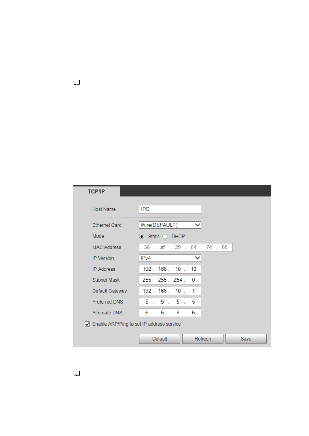
Step 4 Choose Setting > Network > TCP/IP.
The system will display the Setting dialog box, as shown in Figure 5-3.
5 Network Configuration
Figure 5-3 Setting the IP address
Step 5 Set the Mode as Static, and enter the planned start IP, subnet mask and gateway.
NOTE
Set the Mode as DHCP when there is DHCP server in the network, the device will automatically
acquire IP address from the DHCP server.
Issue 01 (2019-02-22) Copyright © Huawei Technologies Co., Ltd. 19
Page 23
IPC6061-FP
Quick Start Guide
Step 6 Click Save to complete modification of device IP address.
----End
5.3 Login Web Interface
Step 1 Open Internet Explorer, enter the modified camera IP address in the address box, and press
Enter.
NOTE
l HTTP is an insecure protocol which may incur security risks. Therefore, you need to enable the
HTTPS protocol to enhance system security. For details, see HTTPS in the User Manual.
l After the HTTPS protocol is enabled, you are advised to access the camera web page by entering
https://camera IP address in the address box of your web browser.
Step 2 Please operate according to the interface prompt if the interface displays guide of Online
Upgrade.
Step 3 Enter the user name and password and click Login.
Step 4 For the first login, click Please click here to download and installthe plug-in., Install
controls as prompted.
5 Network Configuration
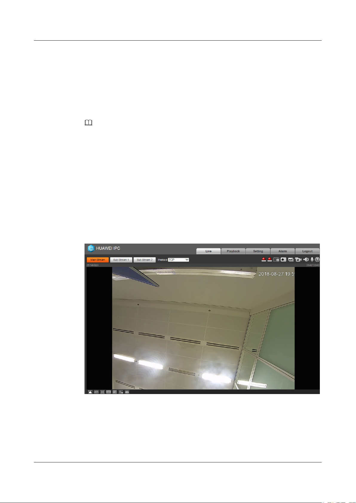
Step 5 The main interface will be shown in after control installation is completed.
Figure 5-4 Web Interface
----End
Issue 01 (2019-02-22) Copyright © Huawei Technologies Co., Ltd. 20
Page 24

IPC6061-FP
Quick Start Guide
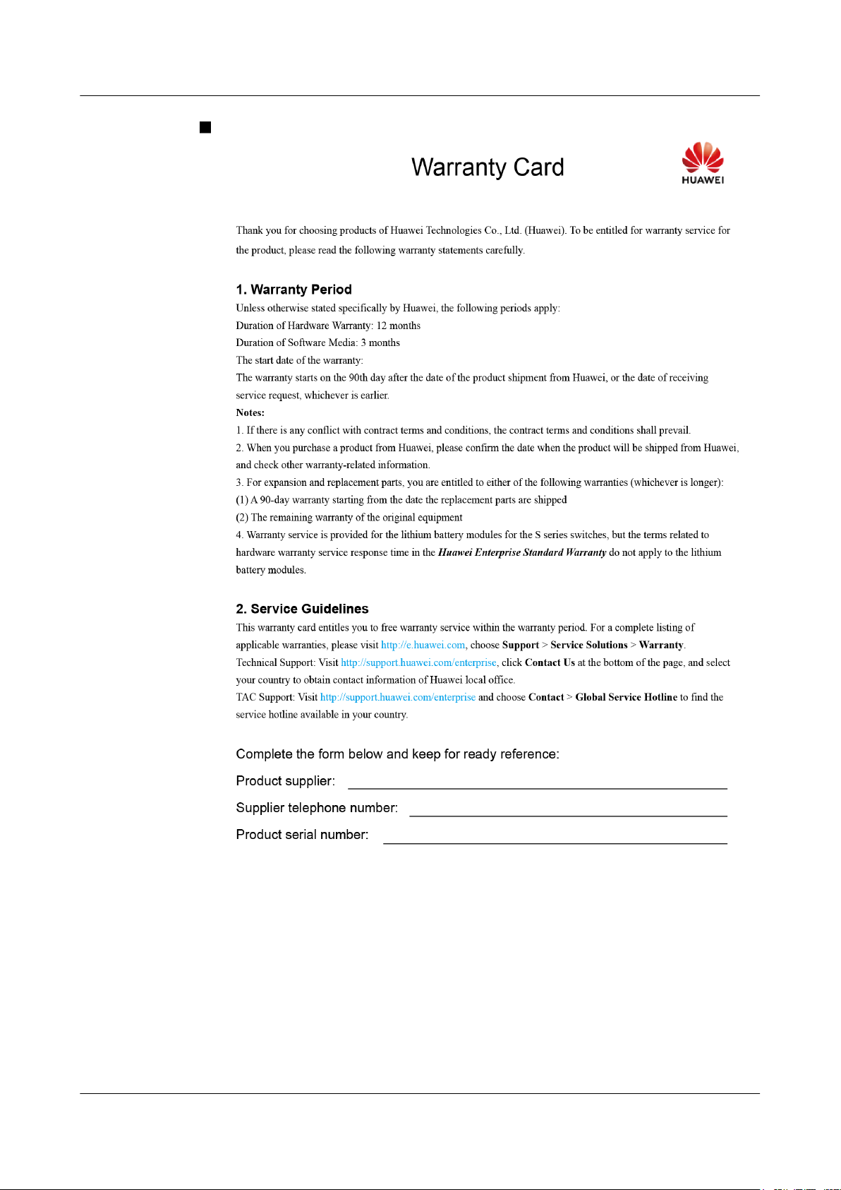
6 Warranty Card
6 Warranty Card
Issue 01 (2019-02-22) Copyright © Huawei Technologies Co., Ltd. 21
Page 25
IPC6061-FP
Quick Start Guide
6 Warranty Card
Issue 01 (2019-02-22) Copyright © Huawei Technologies Co., Ltd. 22
 Loading...