

Page 1
BTS3701B User Guide
Product Version
The following table lists the product versions corresponding to this document.
Product Name Product Version
BTS3701B V300R003
Change History
Version Change History
01 (2010-03-30) First commercial release
页码,1/8BTS3701B User Guide
Organization
z
Hardware Description
This document describes the components, functions, specifications, cable classifications,
cable specifications, and cable connections of the BTS3701B.
Huawei Proprietary and Confidential
Copyright © Huawei Technologies Co., Ltd.
Hardware Description
This document describes the components, functions, specifications, cable classifications, cable
specifications, and cable connections of the BTS3701B.
z
BTS3701B System
The BTS3701B system is composed of the BTS3701B and the power adapter.
z
Cables of the pBTS3701
The BTS3701B cables consist of a power cable and Ethernet cables.
Parent topic:
BTS3701B User Guide
Huawei Proprietary and Confidential
Copyright © Huawei Technologies Co., Ltd.
BTS3701B System
The BTS3701B system is composed of the BTS3701B and the power adapter.
z
BTS3701B
This section describes the exterior of the BTS3701B and meanings of ports, buttons, and
indicators on the panels.
z
Power Adapter
The power adapter converts the 100 V AC/220 V AC to 12 V DC and leads power to the
2010-5-14file://C:\Documents and Settings\w00110219\Local Settings\Temp\~hhB...
Page 2
页码,2/8BTS3701B User Guide
BTS3701B.
z
z
PSE
The power sourcing equipment (PSE) provides power for the BTS3701B over an Ethernet
cable in the power over Ethernet (POE) mode.
PD
The powered device (PD) obtains the power from the Ethernet cable and converts it to 12 V
DC to provide power for the BTS3701B.
Parent topic:
Huawei Proprietary and Confidential
Copyright © Huawei Technologies Co., Ltd.
Hardware Description
BTS3701B
This section describes the exterior of the BTS3701B and meanings of ports, buttons, and
indicators on the panels.
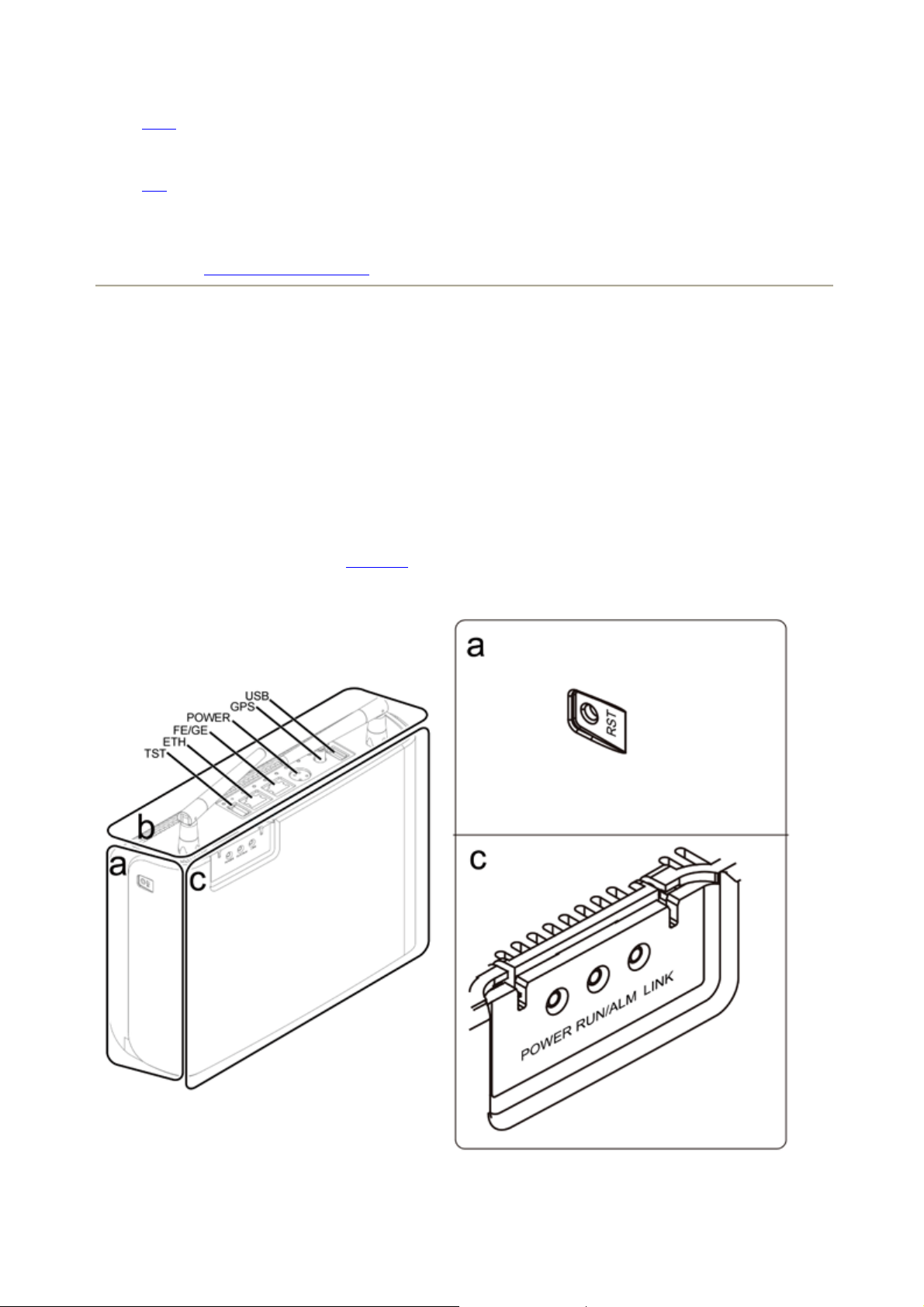
Exterior
The dimensions of the BTS3701B are (width x depth x height): 230 mm (9.06 in.) x 430 mm
(16.93 in.) x 610 mm (24.02 in.). Figure 1 shows the exterior of the BTS3701B.
Figure 1
Exterior of the BTS3701B
Panels
2010-5-14file://C:\Documents and Settings\w00110219\Local Settings\Temp\~hhB...
Page 3
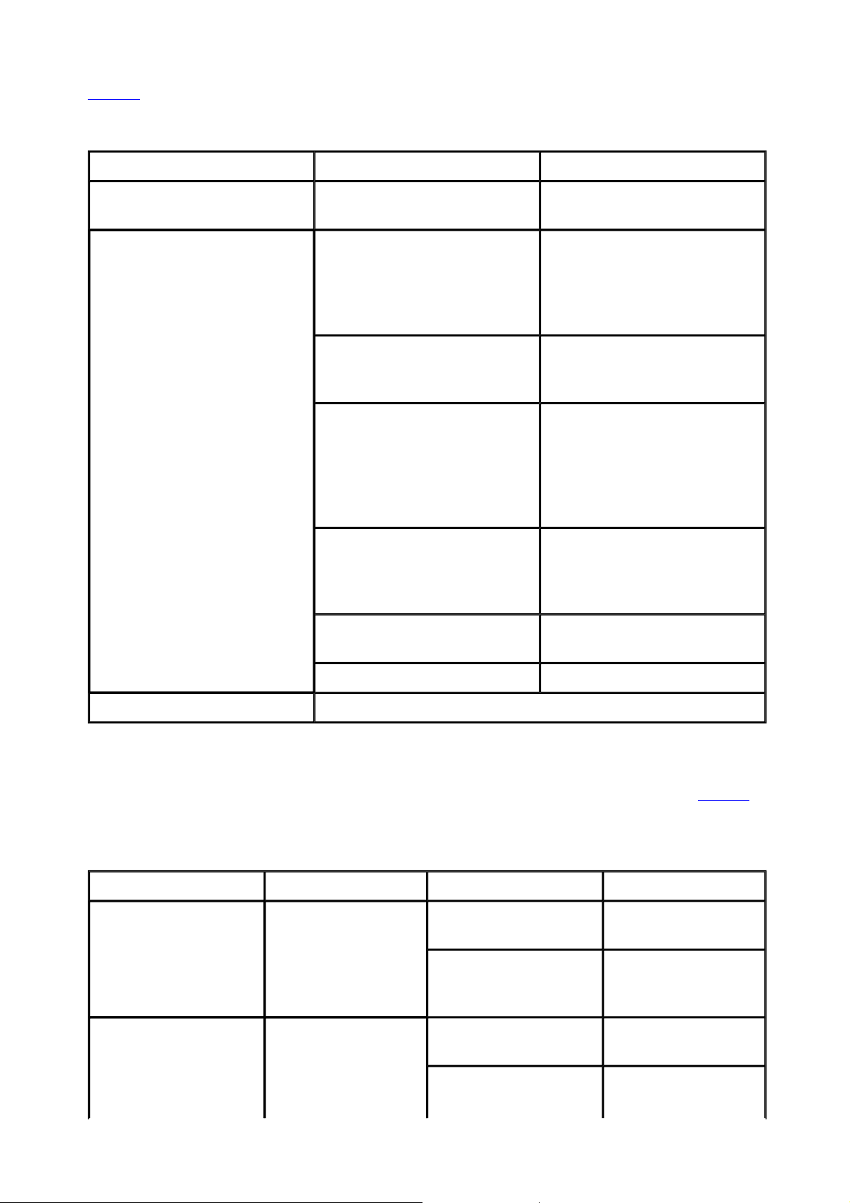
Table 1 describes the panels of the BTS3701B.
页码,3/8BTS3701B User Guide
Table 1
Item Label Description
Side panel (a) RST Reset button. It is used for the
TST Test port. It uses a USB
ETH Commissioning port. It uses an
FE/GE Ethernet port for services. It
Top panel (b)
POWER Power input port. It uses a 4-
Panels of the BTS3701B
reset of the base station (BS).
connector to connect the test
instrument. It provides 10
MHz clock signals and frame
synchronization signals.
RJ45 connector and provides a
bandwidth of 10/100 Mbps.
uses an RJ45 connector and
provides a bandwidth of
100/1,000 Mbps. It is used for
the transmission of service
data.
pin socket connector and
provides 12 V DC for the
BTS3701B.
GPS Port for GPS antenna. It uses
an SMA connector.
USB Standard USB port reserved.
Indicators See table 2.
Indicators
The BTS3701B has three indicators which indicate the running status of the BTS3701B. Table 2
describes the indicators on the BTS3701B.
Table 2
Indicator Color Status Description
POWER Green
Indicators on the BTS3701B
On
Off
Blinking (green) (on for
1s and off for 1s)
The power supply is
normal.
There is no power
supply or the
equipment is faulty.
The equipment is
running normally.
Blinking (green) (on for
The equipment is
being loaded or the
2010-5-14file://C:\Documents and Settings\w00110219\Local Settings\Temp\~hhB...
Page 4

页码,4/8BTS3701B User Guide
RUN/ALM Red and green
LINK Green
Parent topic:
BTS3701B System
0.125s and off for
0.125s)
On (red)
Blinking (red) (on for
1s and off for 1s)
On
Blinking (green) (on for
0.125s and off for
0.125s)
Off
equipment is not
started.
An alarm is generated
and the BTS3701B
needs to be replaced.
An alarm is generated
and the fault should
be rectified based on
the reported alarm.
The FE port is
securely connected.
Data is being
transmitted and
received over the FE
port.
The FE port is not
connected.
Huawei Proprietary and Confidential
Copyright © Huawei Technologies Co., Ltd.
Power Adapter
The power adapter converts the 100 V AC/220 V AC to 12 V DC and leads power to the
BTS3701B.
Figure 1 shows the exterior of the power adapter.
Figure 1
Exterior of the power adapter
NOTE:
In the previous figure, 1 indicates the power conversion unit, 2 indicates the DC output cable, and
3 indicates the 4-pin connector. The DC output cable is 1.5 m (4.92 ft). It is terminated with a 4pin power adapter at one end and is connected to the POWER port on the BTS3701B.
Parent topic:
Huawei Proprietary and Confidential
BTS3701B System
2010-5-14file://C:\Documents and Settings\w00110219\Local Settings\Temp\~hhB...
Page 5

页码,5/8BTS3701B User Guide
Copyright © Huawei Technologies Co., Ltd.
PSE
The power sourcing equipment (PSE) provides power for the BTS3701B over an Ethernet cable in
the power over Ethernet (POE) mode.
Exterior
Figure 1 shows the exterior of the PSE.
Figure 1
Ports
Table 1 describes the ports on the PSE.
Exterior of the PSE
Table 1
Port Port Silkscreen Description
Power port - Used for the power input
POE port DATA&POWER OUT Used for the output of hybrid
Ethernet port DATA IN Used for the input of data
Parent topic:
Huawei Proprietary and Confidential
Copyright © Huawei Technologies Co., Ltd.
BTS3701B System
Ports on the PSE
signals of the PSE
signals
PD
The powered device (PD) obtains the power from the Ethernet cable and converts it to 12 V DC to
provide power for the BTS3701B.
2010-5-14file://C:\Documents and Settings\w00110219\Local Settings\Temp\~hhB...
Page 6

Exterior
Figure 1 shows the exterior of the PD.
页码,6/8BTS3701B User Guide
Figure 1
Ports
Table 1 describes the ports on the PD.
Port Port Silkscreen Description
POE port POWER&DATA IN Used for the data and power
Ethernet port DATA OUT Used for the output of data
Exterior of the PD
Table 1
Ports on the PD
input of the PD
signals of the PD and
connected to the Ethernet port
on the BTS3701B
Power port PWR OUT Connected to the POWER port
on the BTS3701B
Output selection DC OUT Output selection (12 V/24 V),
12 V for the BTS3701B
Parent topic:
Huawei Proprietary and Confidential
Copyright © Huawei Technologies Co., Ltd.
BTS3701B System
Cables of the pBTS3701
The BTS3701B cables consist of a power cable and Ethernet cables.
z
Power Cable
The power cable is used for connecting the AC power wiring bar and provides power for the
power adapter.
z
Ethernet Cable
The Ethernet cable connects the BTS3701B and the transmission equipment of an operator.
Parent topic:
Hardware Description
Huawei Proprietary and Confidential
2010-5-14file://C:\Documents and Settings\w00110219\Local Settings\Temp\~hhB...
Page 7

页码,7/8BTS3701B User Guide
Copyright © Huawei Technologies Co., Ltd.
Power Cable
The power cable is used for connecting the AC power wiring bar and provides power for the
power adapter.
Exterior
Figure 1 shows the exterior of the power cable.
Figure 1
In the previous figure, 1 indicates the male connector and 2 indicates the C7 female connector.
Different countries have different power supply standards. The exterior of the cables depends on
actual requirements.
Installation Position
Table 1 describes the connections of the power cable.
One End (PA Male Connector) Is Connected
to...
Exterior of the power cable
NOTE:
Table 1
Connections of the power cable
The Other End (C7 Female Connector) Is
Connected to...
AC power wiring bar Power adapter
Parent topic:
Huawei Proprietary and Confidential
Copyright © Huawei Technologies Co., Ltd.
Cables of the pBTS3701
Ethernet Cable
The Ethernet cable connects the BTS3701B and the transmission equipment of an operator.
Exterior
Both ends of the Ethernet cable are terminated with RJ45 connectors, as shown in Figure 1.
Figure 1
Exterior of the Ethernet cable
2010-5-14file://C:\Documents and Settings\w00110219\Local Settings\Temp\~hhB...
Page 8

Pin Assignment
页码,8/8BTS3701B User Guide
Table 1
X1 End Color Type X2 End
X1.2 Orange Twisted pair wire X2.2
X1.1 White/Orange X2.1
X1.6 Green Twisted pair wire X2.6
X1.3 White/Green X2.3
X1.4 Blue Twisted pair wire X2.4
X1.5 White/Blue X2.5
X1.8 Brown Twisted pair wire X2.8
X1.7 White/Brown X2.7
Installation Position
Table 2 describes the connections of the Ethernet cable.
Pin assignments of the Ethernet cable
Table 2
Connections of the Ethernet cable
One End Is Connected to... The Other End Is Connected to...
Transmission equipment of an operator FE/GE port on the BTS3701B
Parent topic:
Huawei Proprietary and Confidential
Copyright © Huawei Technologies Co., Ltd.
Cables of the
pBTS3701
2010-5-14file://C:\Documents and Settings\w00110219\Local Settings\Temp\~hhB...
 Loading...