

Page 1

HUAWEI
Airbridge BTS3606&3606A CDMA Base Station
Installation Manual – BTS3606A Cabinet Installation
V200R001
Huawei Technologies Proprietary
Page 2

Airbridge BTS3606&3606A CDMA Base Station
Installation Manual
Volume
Manual Version
Product Version
BOM
Huawei Technologies Co., Ltd. provides customers with comprehensive technical support
and service. Please feel free to contact our local office or company headquarters.
Huawei Technologies Co., Ltd.
Address: Administration Building, Huawei Technologies Co., Ltd.,
Bantian, Longgang District, Shenzhen, P. R. China
Postal Code: 518129
Website: http://www.huawei.com
BTS3606A Cabinet Installation
T2-030463-20050202-C-2.11
V200R001
31041463
Email: support@huawei.com
Huawei Technologies Proprietary
Page 3

Copyright © 2005 Huawei Technologies Co., Ltd.
All Rights Reserved
No part of this manual may be reproduced or transmitted in any form or by any
means without prior written consent of Huawei Technologies Co., Ltd.
Trademarks
, HUAWEI, C&C08, EAST8000, HONET, , ViewPoint, INtess, ETS, DMC,
TELLIN, InfoLink, Netkey, Quidway, SYNLOCK, Radium,
M900/M1800,
TELESIGHT, Quidview, Musa, Airbridge, Tellwin, Inmedia, VRP, DOPRA, iTELLIN,
iNET, NETENGINE, OptiX, iSite, U-SYS, iMUSE, OpenEye,
HUAWEI OptiX, C&C08
Lansway, SmartAX, infoX, and TopEng are trademarks of Huawei Technologies
Co., Ltd.
All other trademarks and trade names mentioned in this manual are the prope rty of
their respective holders.
Notice
The information in this manual is subject to change without notice. Every effort has
been made in the preparation of this manual to ensure accuracy of the contents, but
all statements, information, and recommendations in this manual do not constitute
the warranty of any kind, express or implied.
Huawei Technologies Proprietary
Page 4
About This Manual
Release Notes
This manual applies to Airbridge BTS3606A CDMA Base Station V200R001.
Related Manuals
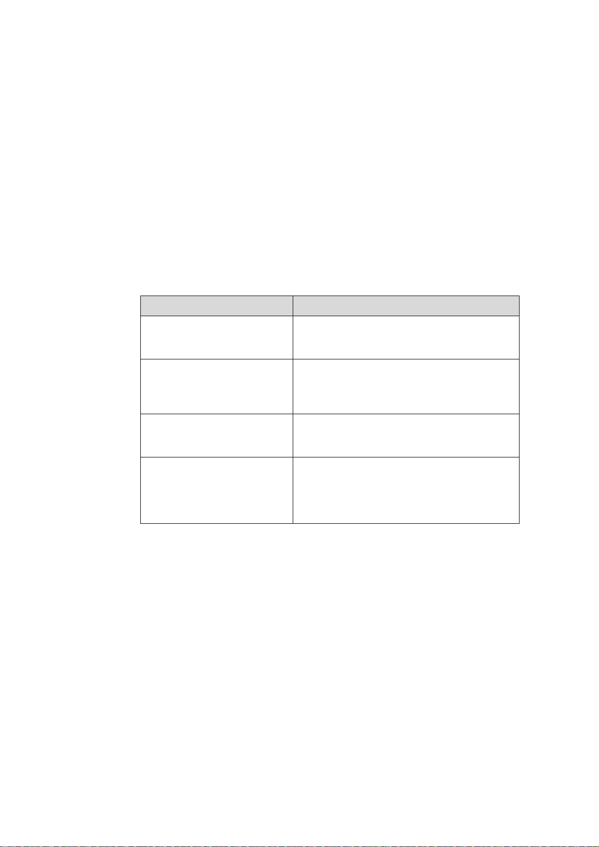
The related manuals are listed in the following table.
Manual Content
Organization
The manual introduces the installation procedures of the Airbridge BTS3606A CDMA
Base Station. It is divided into six chapters:
Airbridge BTS3606&3606A
CDMA Base Station Technical
Manual
Airbridge BTS3606&3606A
CDMA Base Station
Installation Manual
Airbridge BTS3606&3606A
CDMA Base Station Data
Configuration Manual
Airbridge BTS3606&3606A
CDMA Base Station
Maintenance Manual
Covers the system description, system
architecture and principles, interface protocols,
and services flows of the BTS3606/BTS3606A.
Covers the hardware installation, software
installation and commissioning, and
installation reference for the
BTS3606/BTS3606A.
Introduces the data configuration tasks and
configuration procedures of the
BTS3606/BTS3606A.
Introduces the routine/emergency maintenance,
troubleshooting, and part replacement
procedures as well as common operations
involved in the BTS3606/BTS3606A
maintenance.
Chapter 1 Installation Preparations introduces how to arrange the personnel, ch eck
the installation environment, prepare project plan, make kickoff coordination, and
conduct the unpacking check.
Chapter 2 Installing Cabinet Base or Channel Steel introduces the physical features
of the base for BTS3606A cabinet and the installation procedures.
Huawei Technologies Proprietary
Page 5
Chapter 3 Installing Cabinet and Cabinet Equipment introduces how to install the
BTS3606A cabinet and the battery cabinet, how to install/remove the cabinet doors,
and how to install the boards/modules and the batteries.
Chapter 4 Installing Outdoor Transmission and Power Interface Boxes intr oduces
the structures of the outdoor transmission and power interface boxes, the installation
procedures, and the usage of the two interface boxes.
Chapter 5 Installing Cables introduces the categories of cables installed on site,
cable distribution methods, description of water-proof components, and procedures of
connecting various cables in BTS3606A cabinet, battery cabinet, and combined
cabinets.
Chapter 6 Checking Cabinet Installation provides the installation checklists after the
cabinet equipment is installed.
Intended Audience
The manual is intended for the following readers:
Installation engineers and technicians
z
Operation and maintenance personnel
z
Conventions
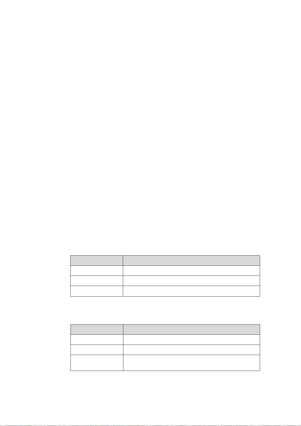
The manual uses the following conventions:
I. General conventions
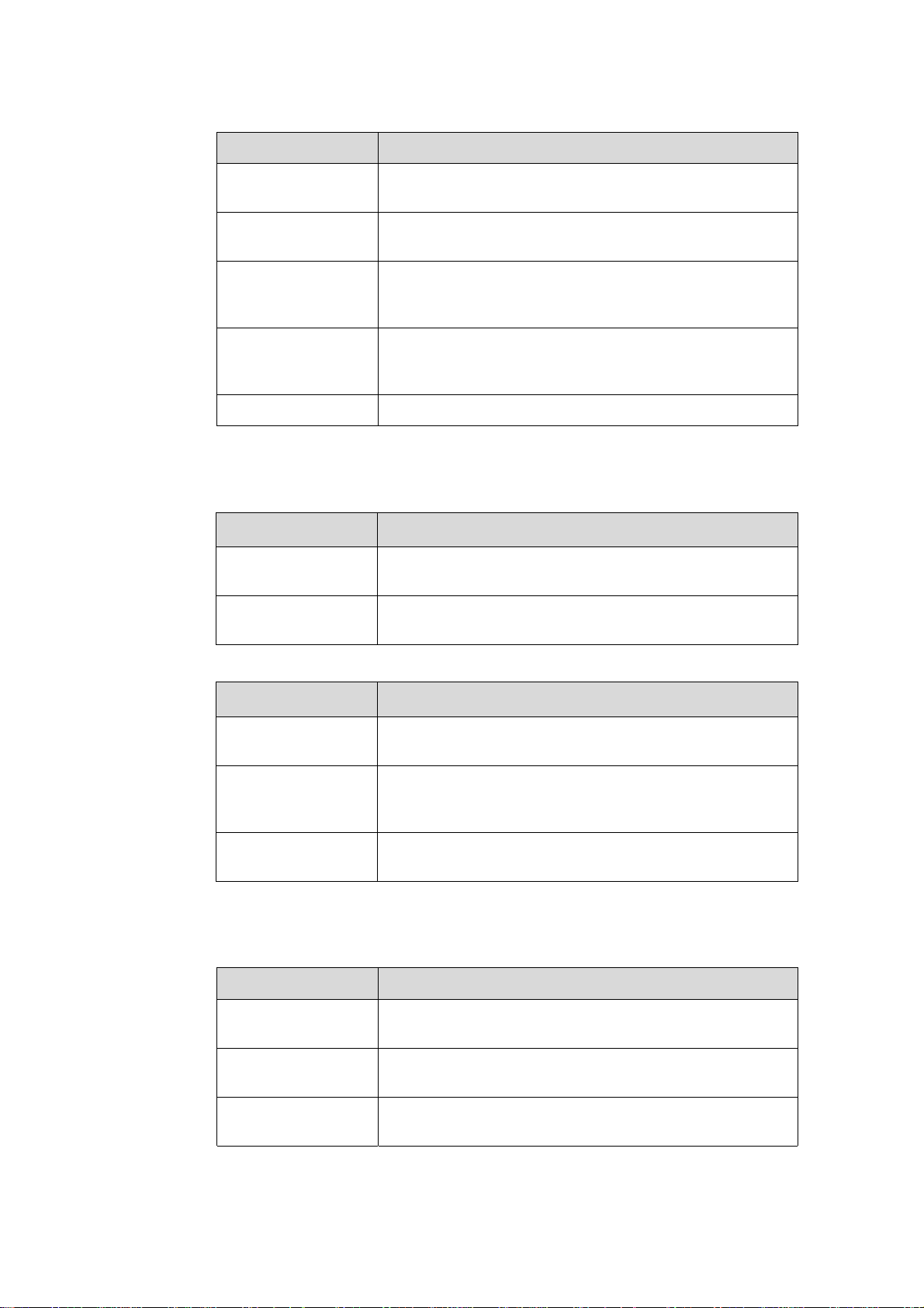
II. Command conventions
Convention Description
Arial Normal paragraphs are in Arial.
Boldface
Courier New
Headings are in Boldface.
Terminal Display is in Courier New.
Convention Description
Boldface
italic
[ ]
The keywords of a command line are in Boldface.
Command arguments are in italic.
Items (keywords or arguments) in square brackets [ ] are
optional.
Huawei Technologies Proprietary
Page 6
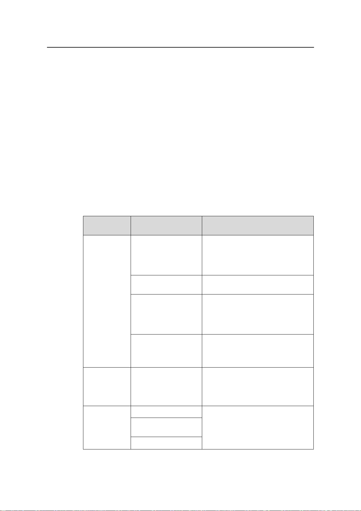
Convention Description
{ x | y | ... }
[ x | y | ... ]
{ x | y | ... } *
[ x | y | ... ] *
# A line starting with the # sign is comments.
III. GUI conventions
Convention Description
Boldface
/
Alternative items are grouped in braces and separated by
vertical bars. One is selected.
Optional alternative items are grouped in square brackets
and separated by vertical bars. One or none is selected.
Alternative items are grouped in braces and separated by
vertical bars. A minimum of one or a maximum of all can be
selected.
Optional alternative items are grouped in square brackets
and separated by vertical bars. Many or none can be
selected.
Button names and menu items are in Boldface. For
example, click OK.
Multi-level menus are in bold and separated by forward
slashes. For example, select the File/Create/Folder menu.
Convention Description
< >
[ ]
/
IV. Keyboard operation
Format Description
<Key>
<Key1+Key2>
<Key1, Key2>
Button names are inside angle brackets. For example, click
the <OK> button.
Window names, menu items, data table and field names
are inside square brackets. For example, pop up the [New
User] window.
Multi-level menus are separated by forward slashes. For
example, [File/Create/Folder].
Press the key with the key name inside angle brackets. For
example, <Enter>, <Tab>, <Backspace>, or <A >.
Press the keys concurrently. For example, <Ctrl+Alt+A>
means the three keys should be pressed concurrently.
Press the keys in turn. For example, <Alt, A> means the
two keys should be pressed in turn.
Huawei Technologies Proprietary
Page 7

V. Mouse operation
Action Description
Select
Click
Double-Click
Drag
Press and hold the primary mouse button (left mouse
button by default).
Select and release the primary mouse button without
moving the pointer.
Press the primary mouse button twice continuously and
quickly without moving the pointer.
Press and hold the primary mouse button and move the
pointer to a certain position.
VI. Symbols
Eye-catching symbols are also used in the manual to highlight the points worthy of
special attention during the operation. They are defined as follows:
Caution, Warning, Danger: Means reader be extremely careful during the
operation.
Note, Comment, Tip, Knowhow, Thought: Means a complementary description.
Environmental Protection
This product has been designed to comply with the requirements on environmental
protection. For the proper storage, use and disposal of this product, national laws and
regulations must be observed.
Huawei Technologies Proprietary
Page 8

Installation Manual – BTS3606A Cabinet Installation
Airbridge BTS3606&3606A CDMA Base Station Table of Contents
Table of Contents
Chapter 1 Installation Preparations.............................................................................................1-1
1.1 Project Files....................................................................................................................... 1-1
1.2 Tools and Instruments .......................................................................................................1-2
1.3 Installation Conditions........................................................................................................ 1-3
1.3.1 Site Requirements................................................................................................... 1-3
1.3.2 Load-bearing Capacity Requirements .................................................................... 1-3
1.3.3 Space Requirements............................................................................................... 1-4
1.3.4 Power Supply and Grounding Requirements.......................................................... 1-5
1.3.5 Requirements for Transmission System................................................................. 1-5
1.3.6 Requirements for Antenna System.........................................................................1-5
1.4 Unpacking.......................................................................................................................... 1-5
1.4.1 Unpacking Requirements........................................................................................1-6
1.4.2 Unpacking Wooden Case ....................................................................................... 1-7
1.4.3 Unpacking Carton ................................................................................................... 1-9
Chapter 2 Installing Cabinet Base or Channel Steel..................................................................2-1
2.1 Introduction to Cabinet Base ............................................................................................. 2-1
2.1.1 Base for BTS3606A Cabinet................................................................................... 2-1
2.1.2 Base for Battery Cabinet.........................................................................................2-1
2.2 Installation Flowchart.........................................................................................................2-2
2.3 Installing Cabinet Base......................................................................................................2-3
2.3.1 Laying Out Installation Position............................................................................... 2-3
2.3.2 Casting Cement Plinth ............................................................................................ 2-5
2.3.3 Positioning the Base ............................................................................................... 2-6
2.3.4 Drilling Holes and Installing Expansion Bolts..........................................................2-8
2.3.5 Fastening the Base ...............................................................................................2-10
2.4 Installing Channel Steel...................................................................................................2-11
2.4.1 Laying out Installation Position..............................................................................2-12
2.4.2 Casting Cement Plinths......................................................................................... 2-12
2.4.3 Preparing Channel Steel....................................................................................... 2-12
2.4.4 Positioning Channel Steel..................................................................................... 2-12
2.4.5 Drilling Holes and Installing Expansion Bolts........................................................2-12
2.4.6 Fastening Channel Steel.......................................................................................2-12
Chapter 3 Installing Cabinet and Cabinet Equipment ............................................................... 3-1
3.1 Installation of Cabinet........................................................................................................3-1
3.1.1 Positioning Cabinet................................................................................................. 3-1
3.1.2 Leveling Cabinet......................................................................................................3-2
3.1.3 Fastening Cabinet...................................................................................................3-4
Huawei Technologies Proprietary
i
Page 9

Installation Manual – BTS3606A Cabinet Installation
Airbridge BTS3606&3606A CDMA Base Station Table of Contents
3.1.4 Installing Accessories.............................................................................................. 3-6
3.1.5 Removing Lugs (Optional) ......................................................................................3-8
3.2 Installation of Auxiliary Battery Cabinet............................................................................. 3-8
3.2.1 Positioning Cabinet................................................................................................. 3-8
3.2.2 Leveling Cabinet......................................................................................................3-9
3.2.3 Fastening Cabinet...................................................................................................3-9
3.2.4 Installing Accessories.............................................................................................. 3-9
3.2.5 Removing Lugs .....................................................................................................3-11
3.3 Installation and Removal of BTS3606A Cabinet Front Door...........................................3-11
3.3.1 Removing Front Door............................................................................................ 3-11
3.3.2 Removing Rear Door ............................................................................................ 3-11
3.4 Installation of Cabinet Equipment.................................................................................... 3-12
3.4.1 Installing Boards in Baseband Subrack................................................................3-12
3.4.2 Installing Modules in RF Subrack..........................................................................3-14
3.4.3 Installing Power Module........................................................................................3-15
3.4.4 Installing Built-in Batteries.....................................................................................3-16
3.4.5 Installing Built-in Transmission Equipment........................................................... 3-16
3.5 Installation or Removal of Auxiliary Battery Cabinet Doors............................................. 3-16
3.5.1 Opening the Front Door ........................................................................................ 3-16
3.5.2 Removing the Rear Door ...................................................................................... 3-17
3.6 Installation of Batteries in Auxiliary Battery Cabinet........................................................ 3-18
3.7 Illustration of Cabinets After Installed on Cement Plinth .................................................3-19
Chapter 4 Installing Outdoor Transmission and Power Interface Boxes................................ 4-1
4.1 Introduction to Outdoor Transmission and Power Interface Boxes................................... 4-1
4.1.1 Outdoor Transmission Interface Box.......................................................................4-1
4.1.2 Outdoor Power Interface Box.................................................................................. 4-2
4.2 Installing Outdoor Transmission and Power Interface Box ............................................... 4-4
4.2.1 Mounting Transmission Interface Box on the Wall.................................................. 4-4
4.2.2 Mounting Transmission Interface Box on the Steel Pole........................................ 4-6
4.3 Using Internal Components of Transmission Interface Box.............................................. 4-7
4.3.1 Using 120Ω DDF Unit..............................................................................................4-8
4.3.2 Using 75Ω DDF Unit................................................................................................4-9
4.3.3 Using Grounding Busbar.........................................................................................4-9
4.3.4 Using 12-Core Fiber Fusing and Distributing Assemblies ....................................4-10
4.4 Installing Outdoor Power Input Components...................................................................4-12
4.4.1 Installing Diesel Air Breaker Assemblies .............................................................. 4-12
4.4.2 Installing Grounding Cable for Enclosure ............................................................. 4-13
4.4.3 Installing Input Components of Single-phase Mains and Diesel...........................4-14
4.4.4 Installing Single-phase Mains Input Components................................................. 4-15
4.4.5 Installing Input Components of Three-phase Mains and Diesel........................... 4-16
4.4.6 Installing Three-phase Mains Input Components .................................................4-17
Huawei Technologies Proprietary
ii
Page 10

Installation Manual – BTS3606A Cabinet Installation
Airbridge BTS3606&3606A CDMA Base Station Table of Contents
Chapter 5 Installing Cables.......................................................................................................... 5-1
5.1 Types of Cables and Related Concepts............................................................................ 5-1
5.1.1 Types of Cables for BTS3606A Deployment.......................................................... 5-1
5.1.2 Related Concepts.................................................................................................... 5-3
5.2 Cabling Diagram................................................................................................................5-4
5.3 Installing RF Cables........................................................................................................... 5-7
5.3.1 Connecting RF Jumper to Feeder........................................................................... 5-8
5.3.2 Installing RF Cable Between CDDU/CHPA/CTRM (Single-Channel).....................5-9
5.3.3 Installing RF Cable Between CDDU/CMPA/CMTR (Multi-Channel).....................5-15
5.4 Installing E1/T1 Cables....................................................................................................5-19
5.4.1 Planning Installation Position of E1/T1 Cables..................................................... 5-19
5.4.2 Installing Waterproof Components........................................................................ 5-21
5.4.3 Shielding E1/T1 Cables......................................................................................... 5-30
5.4.4 Connecting E1/T1 Cables..................................................................................... 5-32
5.4.5 Connecting E1/T1 Trunks to Outdoor Transmission Interface Box ...................... 5-33
5.5 Installing Optical Fibers ...................................................................................................5-33
5.5.1 Cabling Principles .................................................................................................5-33
5.5.2 Installing Optical Fibers Cascading the ODU3601C............................................. 5-34
5.6 Installing GPS Lightning Arrester and GPS Clock Cables .............................................. 5-34
5.7 Installing Power Cables................................................................................................... 5-36
5.7.1 Principles of Cabling Power Cables...................................................................... 5-36
5.7.2 Making Power Cables........................................................................................... 5-38
5.7.3 Connecting Power Cables..................................................................................... 5-38
5.8 Installing Cabinet PGND Cables......................................................................................5-44
5.8.1 Making Cabinet PGND Cables..............................................................................5-44
5.8.2 Grounding Requirement........................................................................................ 5-44
5.8.3 Connecting PGND Cable of the Cabinet............................................................... 5-45
5.9 Installing Built-in Batteries ...............................................................................................5-46
5.10 Installing Cables of Battery Cabinet...............................................................................5-50
5.10.1 Introduction to Cables of Battery Cabinet........................................................... 5-50
5.10.2 Installing Internal Cables of the Battery Cabinet.................................................5-51
5.10.3 Installing External Cables of the Battery Cabinet................................................ 5-52
5.10.4 Installing Cables between Battery Cabinet and BTS3606A Cabinet..................5-54
Chapter 6 Checking Cabinet Installation .................................................................................... 6-1
6.1 Check Before Power-on..................................................................................................... 6-1
6.1.1 Equipment Installation Check.................................................................................. 6-1
6.1.2 Cable Installation Check ......................................................................................... 6-2
6.2 Power-on Check ................................................................................................................6-3
6.2.1 Power-on Check of Primary Power Supply.............................................................6-3
6.2.2 Power-on Check of Power Modules........................................................................ 6-4
6.2.3 Power-on Check of Air Conditioner......................................................................... 6-4
6.2.4 Power-on Check of Integrated Equipment..............................................................6-5
Huawei Technologies Proprietary
iii
Page 11

Installation Manual – BTS3606A Cabinet Installation
Airbridge BTS3606&3606A CDMA Base Station Table of Contents
Index ................................................................................................................................................i-1
Huawei Technologies Proprietary
iv
Page 12

Installation Manual – BTS3606A Cabinet Installation
Airbridge BTS3606&3606A CDMA Base Station List of Figures
List of Figures
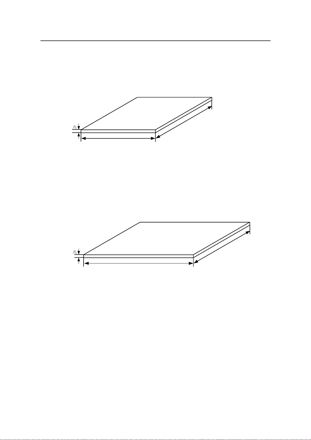
Figure 1-1 Dimensions of cement base of BTS3606A single cabinet (unit: mm)..................1-4
Figure 1-2 Dimensions of cement base of BTS3606A cabinet and auxiliary battery cabinet (unit:
mm) .................................................................................................................................1-4
Figure 1-3 Straightening the tongues.....................................................................................1-8
Figure 1-4 Removing the cover..............................................................................................1-8
Figure 1-5 Removing all left wooden boards.........................................................................1-9
Figure 1-6 Carton packed with boards.................................................................................1-10
Figure 2-1 Outline and dimensions of the base for the BTS3606A cabinet...........................2-1
Figure 2-2 Outline and dimensions of the base for the battery cabinet.................................2-2
Figure 2-3 Installation flowchart.............................................................................................2-3
Figure 2-4 Installation position for a BTS3606A cabinet........................................................2-4
Figure 2-5 Installation position for a battery cabinet..............................................................2-5
Figure 2-6 Dimensions of a cement plinth .............................................................................2-6
Figure 2-7 Dimensions of cement plinth for battery cabinet and BTS3606A cabinet............2-6
Figure 2-8 Layout and dimensions of installation holes for a BTS3606A cabinet.................2-7
Figure 2-9 Layout of installation holes when a battery cabinet is configured........................2-8
Figure 2-10 Disassembling expansion bolts..........................................................................2-9
Figure 2-11 Installing the expansion bolt and expansion tube...............................................2-9
Figure 2-12 Fastening the base of BTS3606A ....................................................................2-10
Figure 2-13 Fastening the base of battery cabinet.............................................................. 2-11
Figure 2-14 Preparing channel steel....................................................................................2-12
Figure 3-1 Cabinet bearing points..........................................................................................3-2
Figure 3-2 Leveling a BTS3606A cabinet (Installing cabinet on base)..................................3-3
Figure 3-3 Leveling a BTS3606A cabinet (Installing cabinet on channel steel)....................3-3
Figure 3-4 Opening the front door..........................................................................................3-4
Figure 3-5 Fixing the front door..............................................................................................3-5
Figure 3-6 Installing the burglary-resisting bolt......................................................................3-6
Figure 3-7 Mounting cabling rack...........................................................................................3-7
Figure 3-8 Mounting the rodent-resistant plate......................................................................3-8
Figure 3-9 Leveling a cabinet (battery cabinet) .....................................................................3-9
Figure 3-10 Mounting the cabling rack.................................................................................3-10
Huawei Technologies Proprietary
v
Page 13

Installation Manual – BTS3606A Cabinet Installation
Airbridge BTS3606&3606A CDMA Base Station List of Figures
Figure 3-11 Mounting rodent-resistant plate........................................................................3-10
Figure 3-12 Installing a board (1).........................................................................................3-13
Figure 3-13 Installing a board (2).........................................................................................3-14
Figure 3-14 Installing a board (3).........................................................................................3-14
Figure 3-15 Unlocking the rear door....................................................................................3-17
Figure 3-16 Installing batteries.............................................................................................3-18
Figure 3-17 Removing baffle plates.....................................................................................3-19
Figure 3-18 BTS3606A cabinet installed on cement plinth..................................................3-20
Figure 3-19 Auxiliary battery cabinet installed on cement plinth .........................................3-21
Figure 4-1 Structure of 75Ω transmission interface box........................................................4-1
Figure 4-2 Structure of 120Ω transmission interface box......................................................4-2
Figure 4-3 Internal structure of PSI power interface box.......................................................4-3
Figure 4-4 Default configuration of PSI power interface box.................................................4-4
Figure 4-5 Installation holes of expansion bolts.....................................................................4-5
Figure 4-6 Mounting transmission interface box on the wall .................................................4-5
Figure 4-7 Assembling the beam...........................................................................................4-6
Figure 4-8 Mounting transmission interface box on the steel pole........................................4-7
Figure 4-9 Cabling diagram after 120Ω DDF unit is installed (a)...........................................4-8
Figure 4-10 Cabling diagram after 120Ω DDF unit is installed (b).........................................4-9
Figure 4-11 Cabling diagram after 75Ω DDF unit is installed ................................................4-9
Figure 4-12 Grounding busbar.............................................................................................4-10
Figure 4-13 Structure of 12-core fiber fusing and distributing assemblies ..........................4-10
Figure 4-14 Cabling diagram after 12-core fiber fusing and distributing assemblies are installed
.......................................................................................................................................4-11
Figure 4-15 Mounting diesel air breaker..............................................................................4-12
Figure 4-16 Mounting air breaker interlock device...............................................................4-13
Figure 4-17 Operating air breaker interlock device..............................................................4-13
Figure 4-18 Installing grounding cable for enclosure...........................................................4-14
Figure 4-19 Input of single-phase mains and diesel............................................................4-15
Figure 4-20 Input of single-phase mains..............................................................................4-16
Figure 4-21 Input of three-phase mains and three-phase diesel.........................................4-17
Figure 4-22 Input of three-phase mains...............................................................................4-18
Figure 5-1 Front cabling diagram of the BTS3606A cabinet .................................................5-5
Figure 5-2 Rear cabling diagram of the BTS3606A cabinet..................................................5-6
Huawei Technologies Proprietary
vi
Page 14

Installation Manual – BTS3606A Cabinet Installation
Airbridge BTS3606&3606A CDMA Base Station List of Figures
Figure 5-3 Inlet/outlet of RF cables........................................................................................5-8
Figure 5-4 Inlet/outlet panel after turnover.............................................................................5-8
Figure 5-5 Installing RF cables..............................................................................................5-9
Figure 5-6 O(1) configuration............................................................................................... 5-11
Figure 5-7 O(2) configuration...............................................................................................5-12
Figure 5-8 S(1/1/1) configuration.........................................................................................5-12
Figure 5-9 S(2/2/2) configuration.........................................................................................5-13
Figure 5-10 O(1) power synthesis........................................................................................5-14
Figure 5-11 S(1/1/1) power synthesis..................................................................................5-15
Figure 5-12 O(1) configuration.............................................................................................5-16
Figure 5-13 O(2) configuration.............................................................................................5-16
Figure 5-14 S(1/1/1) configuration.......................................................................................5-17
Figure 5-15 S(2/2/2) configuration.......................................................................................5-18
Figure 5-16 S(3/3/3) configuration.......................................................................................5-18
Figure 5-17 Removing front panel of lightning protection box (for E1/T1 cable installation)5-19
Figure 5-18 Distribution of waterproof components at the cabinet bottom..........................5-20
Figure 5-19 Routing E1/T1 cables.......................................................................................5-21
Figure 5-20 Sealing module.................................................................................................5-22
Figure 5-21 Stripping the core layer of the sealing module.................................................5-22
Figure 5-22 Front view of common sealing module.............................................................5-22
Figure 5-23 Filler module.....................................................................................................5-23
Figure 5-24 Fastening module.............................................................................................5-24
Figure 5-25 Lubricant...........................................................................................................5-24
Figure 5-26 Removing the filling..........................................................................................5-25
Figure 5-27 Stripping the core layer.....................................................................................5-29
Figure 5-28 Daubing lubricant..............................................................................................5-29
Figure 5-29 Leading the cable.............................................................................................5-29
Figure 5-30 Installing the cable............................................................................................5-30
Figure 5-31 Removing the shielding clip..............................................................................5-31
Figure 5-32 Peeling off the outer skin of the E1 cable.........................................................5-31
Figure 5-33 Shielded E1/T1 cable .......................................................................................5-32
Figure 5-34 Connecting E1/T1 cables .................................................................................5-33
Figure 5-35 Removing the front panel of the air intake box.................................................5-34
Figure 5-36 Installing GPS lightning arrester (1) .................................................................5-35
Huawei Technologies Proprietary
vii
Page 15

Installation Manual – BTS3606A Cabinet Installation
Airbridge BTS3606&3606A CDMA Base Station List of Figures
Figure 5-37 Installing GPS lightning arrester (2) .................................................................5-35
Figure 5-38 Wrong and correct operations..........................................................................5-37
Figure 5-39 Making lugs ......................................................................................................5-38
Figure 5-40 Removing the cover of the power lightning protection filter .............................5-39
Figure 5-41 Installing the L1, L2, L3, and N lines................................................................5-40
Figure 5-42 Installing short-circuit sheets (1).......................................................................5-41
Figure 5-43 Installing short-circuit sheets (2).......................................................................5-42
Figure 5-44 AC power lightning arrester used in the case of two-phase power supply ......5-43
Figure 5-45 Connecting the 110 V power cables.................................................................5-43
Figure 5-46 PGND cable of the cabinet...............................................................................5-44
Figure 5-47 Removing the cover the battery cabin..............................................................5-47
Figure 5-48 Pulling out the sliding plate...............................................................................5-47
Figure 5-49 Placing and connecting two batteries...............................................................5-48
Figure 5-50 Pushing the batteries inside the cabin..............................................................5-48
Figure 5-51 Placing another two batteries...........................................................................5-49
Figure 5-52 Connecting the rest cables...............................................................................5-50
Figure 5-53 Access control and temperature sensor cable.................................................5-51
Figure 5-54 Connecting cables in the extended battery cabinet .........................................5-52
Figure 5-55 Connecting external cables of the battery cabinet ...........................................5-53
Figure 5-56 Connecting PGND cables of the battery cabinet..............................................5-53
Figure 5-57 Outlets of the battery cabinet............................................................................5-54
Figure 5-58 Connecting cables of battery cabinet to DC lightning arrester.........................5-55
Figure 6-1 Front panel of the AC power distribution box.......................................................6-4
Huawei Technologies Proprietary
viii
Page 16

Installation Manual – BTS3606A Cabinet Installation
Airbridge BTS3606&3606A CDMA Base Station List of Tables
List of Tables
Table 1-1 Technical documents..............................................................................................1-1
Table 1-2 Tools and instruments ............................................................................................1-2
Table 4-1 Specifications of the TSI-DDF/ODF transmission interface box ............................4-2
Table 4-2 Specifications of the PSI power interface box........................................................4-3
Table 5-1 Cables to be installed for deployment....................................................................5-1
Table 5-2 BTS3606A cable numbering scheme.....................................................................5-6
Table 5-3 Typical configuration of a single cabinet ................................................................5-9
Table 5-4 Specifications of common sealing module...........................................................5-23
Table 5-5 Filler module specifications ..................................................................................5-23
Table 5-6 Cables and number of layers to be removed .......................................................5-26
Table 5-7 Cable diameters and number of layers to be removed........................................5-28
Table 5-8 Power cable specifications...................................................................................5-36
Table 5-9 Description of cables in battery cabinet................................................................5-51
Table 5-10 Connection of external cables of the storage battery.........................................5-54
Table 6-1 Equipment installation checklist .............................................................................6-1
Table 6-2 Cable installation checklist .....................................................................................6-2
Table 6-3 Measured values and corresponding operations...................................................6-5
Huawei Technologies Proprietary
ix
Page 17
Installation Manual – BTS3606A Cabinet Installation
Airbridge BTS3606&3606A CDMA Base Station Chapter 1 Installation Preparations
Chapter 1 Installation Preparations
This chapter introduces the preparations before BTS3606A installation from the
following aspects:
Project Files
z
Tools and Instruments
z
z Installation Conditions
Unpacking
z
1.1 Project Files
Table 1-1 lists the technical documents useful for the hardware installation.
Table 1-1 Technical documents
Document
type
Installation
guide
Product
manual
Document name Description
The design unit appointed by the
Network planning,
construction drawings,
cable connections
customer must prepare the documents.
The customers must provide a copy of
the documents to Huawei prior to the
equipment delivery.
Site survey report
The report is filled in by Huawei survey
engineers during site survey.
The document is prepared by Huawei
Engineering design and
construction drawings
Construction Design Department
according to the equipment
configuration of a site. It is delivered to
the site with the equipment.
BTS3606A CDMA
Outdoor Base Station
Installation Customer
Preparation Instruction
The document guides the customer to
make preparations before cabinet
installation.
Airbridge
BTS3606&3606A
CDMA Base Station
The document must be provided by
Huawei in the delivery.
Installation Manual
Other related
documentation
Contract
List of equipment
configurations
The document must be provided by
Huawei in the delivery.
Delivery list
Huawei Technologies Proprietary
1-1
Page 18

Installation Manual – BTS3606A Cabinet Installation
Airbridge BTS3606&3606A CDMA Base Station Chapter 1 Installation Preparations
1.2 Tools and Instruments
Table 1-2 lists the tools and instruments needed for the installation.
Table 1-2 Tools and instruments
General
tools
Measuring
instruments
Marking
instruments
Drilling
tools
Clamping
tools
Pliers
Long tape, 50 m ribbon tape, 5 m measuring tape,
and 400 mm level bar
Marking pen, ink fountain, and pencil
Percussion drill with matching bits of φ6, φ8, φ10, φ12,
φ14, and φ16; dust cleaner
Flathead screwdrivers (M3 – M6)
Cross screwdrivers (M3 – M6)
Adjustable wrenches
Socket wrenches (M6, M8, M12, M14, M17, and
M19)
Double offset ring spanner (M6, M8, M12, M14, M17,
and M19)
Combination wrenches (M17 and M19)
A set of inner hexagon spanners
Special wrench
A pair of sharp nose pliers, a pair of diagonal pliers, a
pair of pincer pliers, electric hand drill, file, hacksaw,
crowbar, rubber hammer, and nail hammer
Special
tools
Instruments
Hairbrush, a pair of tweezers, paper knife, bellow,
plumb, soldering iron, tin wires, fork, ladder, heat
Auxiliary
tools
blower, solder absorber, insulating tape, power
connector board with 3 single-phase sockets, 3
two-phase sockets, and 3 three-phase sockets
(current capacity > 15 A)
An earth resistance tester, antistatic wrist strap, a pair of antistatic
gloves, wire stripper, a clamping pincers, a feeder cutter, a pair of
crimping pliers for SMB, RJ-45 connector crimping pliers, wire
punchdown tool, wire cutter, a non-conductive screwdriver, safety
knife, stripper for 75Ω coaxial cables, a pair of connector crimping
pliers for 75Ω coaxial cables, and a pair of multi-purpose crimping
pliers
A multi meter, 500 V megaohm meter (for testing the insulation
resistance), BER tester, and optical power meter
Huawei Technologies Proprietary
1-2
Page 19

Installation Manual – BTS3606A Cabinet Installation
Airbridge BTS3606&3606A CDMA Base Station Chapter 1 Installation Preparations
Note:
The equipment supplier provides the tool list and consults to the customer to specify
the tool provider. The wire punchdown tool is delivered along with the cabinet.
Check the meters to ensure that they are qualified for use.
1.3 Installation Conditions
The project supervisor must do the following:
z Check the construction conditions.
Fill out the Installation Environment Checklist.
z
Sign the Kickoff Agreement with the customer if all conditions are ready.
z
Formulate the Project Installation Plan.
z
If the installation is not prepared as required, fill out the Onsite Work Liaison Form to
declare the reason for kickoff postpone.
If the customer needs immediate kickoff, require the time when the installation will be
prepared.
1.3.1 Site Requirements
Check the installation site with respect to its area, height and load-bearing capacity. If
the site cannot satisfy these requirements, it is advised to re-plan the engineering.
1.3.2 Load-bearing Capacity Requirements
The BTS3606A must be installed on a stable and level cement floor. The weight
capacity of the floor must satisfy the weight requirement of the cabinet. If the
BTS3606A is installed on the rooftop, the weight capacity of the rooftop must meet the
weight requirement of the cabinet.
If the installation site cannot satisfy this requirement, it is necessary to fortify it with a
cement base. The following provides the engineering requirements.
I. Cement Base of BTS3606A Single Cabinet
For the BTS3606A cabinet installation, the cement base can be made according to the
appearance and size illustrated in Figure 1-2. For the height of the cement base, the
local environmental condition must be taken into consideration. Make sure that the
cabinet will not suffer water penetration during heavy rain o r flood, and in the season of
Huawei Technologies Proprietary
1-3
Page 20
Installation Manual – BTS3606A Cabinet Installation
Airbridge BTS3606&3606A CDMA Base Station Chapter 1 Installation Preparations
heavy snow, the snow will not cover the lowest air inlet on the cabinet. It is suggested
that the depth of the cement base be larger than 100 mm.
When finish making a cement base, it is necessary to measure its levelness and
plainness. The levelness is required to be equal to or smaller than 5 mm, and the
surface plainness is required to be equal to or smaller than 5 mm.
100
2500
2200
Figure 1-1 Dimensions of cement base of BTS3606A single cabinet (unit: mm)
II. Cement Base of BTS3606A Cabinet and Auxiliary Battery Cabinet
If the auxiliary battery cabinet is selected, the cement base can be made according to
the appearance and dimensions illustrated in Figure 1-2. The requirements are the
same as those for a BTS3606A single cabinet in thickness, levelness, and
smoothness.
100
3700
2200
Figure 1-2 Dimensions of cement base of BTS3606A cabinet and auxiliary battery
cabinet (unit: mm)
III. Cement Base of Auxiliary Battery Cabinet in Capacity Expansion
If you have installed a BTS3606A cabinet, and if you want to expand its battery capacity
by installing an auxiliary battery cabinet, you will have to add the length of the cement
base for the BTS3606A cabinet. See Figure 1-2 for the requirements in appearance
and dimension. The requirements are the same as those for a BTS3606A cabinet in
thickness, levelness, and smoothness.
Huawei Technologies Proprietary
1-4
Page 21

Installation Manual – BTS3606A Cabinet Installation
Airbridge BTS3606&3606A CDMA Base Station Chapter 1 Installation Preparations
1.3.3 Space Requirements
For specific requirements on installation space, see Chapter 2 "Installing Cabinet Base
or Channel Steel".
1.3.4 Power Supply and Grounding Requirements
For the BTS3606A, power supply must meet the following requirements:
There are complete AC power supply facilities and the following power
z
requirements are met:
– In the 220 V AC power input mode, the working voltage range of the cabinet is
176 V AC to 264 V AC or 47 Hz to 63 Hz, and a voltage stabilizer needs to be
configured.
– In the 1 10 V AC power input mode, the wo rking voltage range of the cabinet is 90
V AC to 135 V AC or 47 Hz to 63 Hz, and a voltage stabilizer needs to be
configured.
Besides main supply, there must be a diesel engine supplying standby power.
z
The remote power cables from the BTS3606A are usually routed overhead. The
z
last segment of cables connected to the BTS3606A must be no more than 50 m
long and are routed underground.
AC power distribution switches and AC power cables must be ready for use.
z
The AC power distribution system must have an independent AC safety ground.
z
The AC neutral line is not allowed to be connected to any protection ground of
z
communications facilities.
1.3.5 Requirements for Transmission System
Check that the transmission system is ready from the following aspects:
The accessed transmission system is commissioned and the capacity meets the
z
engineering requirements.
The trunk cables must not be routed overhead outside the equipment room. You
z
must use double-layer shielded cables or metal-coated cables. The outer layer or
the metal coat of the shielded cables must be connected to the grounding bar
outside the equipment room.
1.3.6 Requirements for Antenna System
Check that the antenna system is ready from the following aspects:
The antenna stands are installed as required.
z
The lightning arrester of the antenna system is installed and ground ed as required.
z
Huawei Technologies Proprietary
1-5
Page 22

Installation Manual – BTS3606A Cabinet Installation
Airbridge BTS3606&3606A CDMA Base Station Chapter 1 Installation Preparations
1.4 Unpacking
This section describes the requirements and procedures of unpacking wooden cases
and cartons.
1.4.1 Unpacking Requirements
After the project begins, the project supervisor must check the products together with
the customer.
Check the following points:
The total number of products is consistent with the packing list attached to the
z
packing case.
The arrival place is the installation site.
z
The packing case is in good condition.
z
The cabinet is placed upside down.
z
If the outer package is damaged or soaked; or the equipment is soaked and becomes
rusty, stop unpacking and find the cause. Feed back the situation to the local Huawei
Representative Office.
Note:
To protect the equipment and find out the cause, move the unpacked equipment indoor
for proper storage, and take a photo for the storage site, the rusty or corroded
equipment, packing cases, packaging materials. Keep these photos and store the
unpacked packing cases and packaging materials.
If the outer package is in good condition, follow the procedure below to unpack and
check the equipment:
1) Unpack the case labeled "contains Packing List”, and take out the Packing List.
Check the case according to the Packing List.
2) If shortage and miscarriage occur, fill in the Cargo Shortage and Miscarriage
Report.
3) If cargo damage occurs, fill in the Cargo Replacement Application Form.
4) Sign the Packing List together with the customer.
Huawei Technologies Proprietary
1-6
Page 23
Installation Manual – BTS3606A Cabinet Installation
Airbridge BTS3606&3606A CDMA Base Station Chapter 1 Installation Preparations
Caution:
When transporting and moving equipment, components, or parts, avoid them from
z
colliding with doors, walls or shelves.
Never touch the uncoated surface of equipment, parts, or components with sweat
z
soaked or dirty gloves.
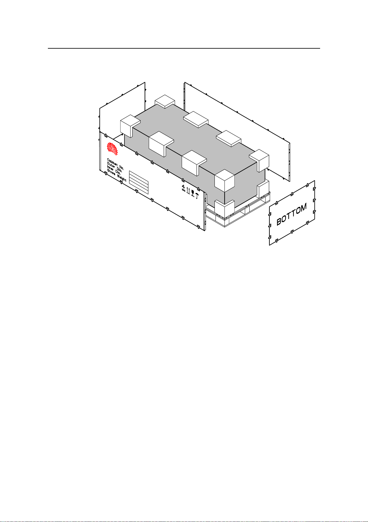
1.4.2 Unpacking Wooden Case
Caution:
Do not put the wooden case upside down. Otherwise, the equipment will suffer severe
damages.
Wooden cases are generally used to pack heavy objects like racks, batteries, and so on.
A rack is usually packed with wooden boards, steel edges, tongues and foamed angle
wraps.
It is recommended to move the packing case into or near the equipment room (if
possible) to avoid damage to the cabinet during the transportation. The unpacking
procedure is as follows:
1) Insert one end of the ejector lever into a hole of the tongue on the cover of the
wooden case.
2) Turn the ejector lever to straighten the tongue, as shown in Figure 1-3. You can
also use a screwdriver or a hammer to handle the tongue.
Huawei Technologies Proprietary
1-7
Page 24

Installation Manual – BTS3606A Cabinet Installation
Airbridge BTS3606&3606A CDMA Base Station Chapter 1 Installation Preparations
SteeledgeWoodenboard
Tongue
Spanner
Figure 1-3 Straightening the tongues
3) After straightening all the tongues on the cover, remove the cover, as shown in
Figure 1-4.
Figure 1-4 Removing the cover
Huawei Technologies Proprietary
1-8
Page 25
Installation Manual – BTS3606A Cabinet Installation
Airbridge BTS3606&3606A CDMA Base Station Chapter 1 Installation Preparations
4) Straighten all the tongues that join the wooden boards around the wooden case
and remove the wooden boards, as shown in Figure 1-5.
Figure 1-5 Removing all left wooden boards
5) Unpack other cases in the same way.
When handling the cabinet, hold on the solid places such as the upper cable rack or
bone frame. Do not use too much force on places with poor rigidity, such as cable
supports, cable fixing beams, to avoid any damage to the cabinet or any accident.
Remove the lining board of the rack at the place where the cabinet is to be installed.
Otherwise, boards and signal cables may be damaged in the conveyance.
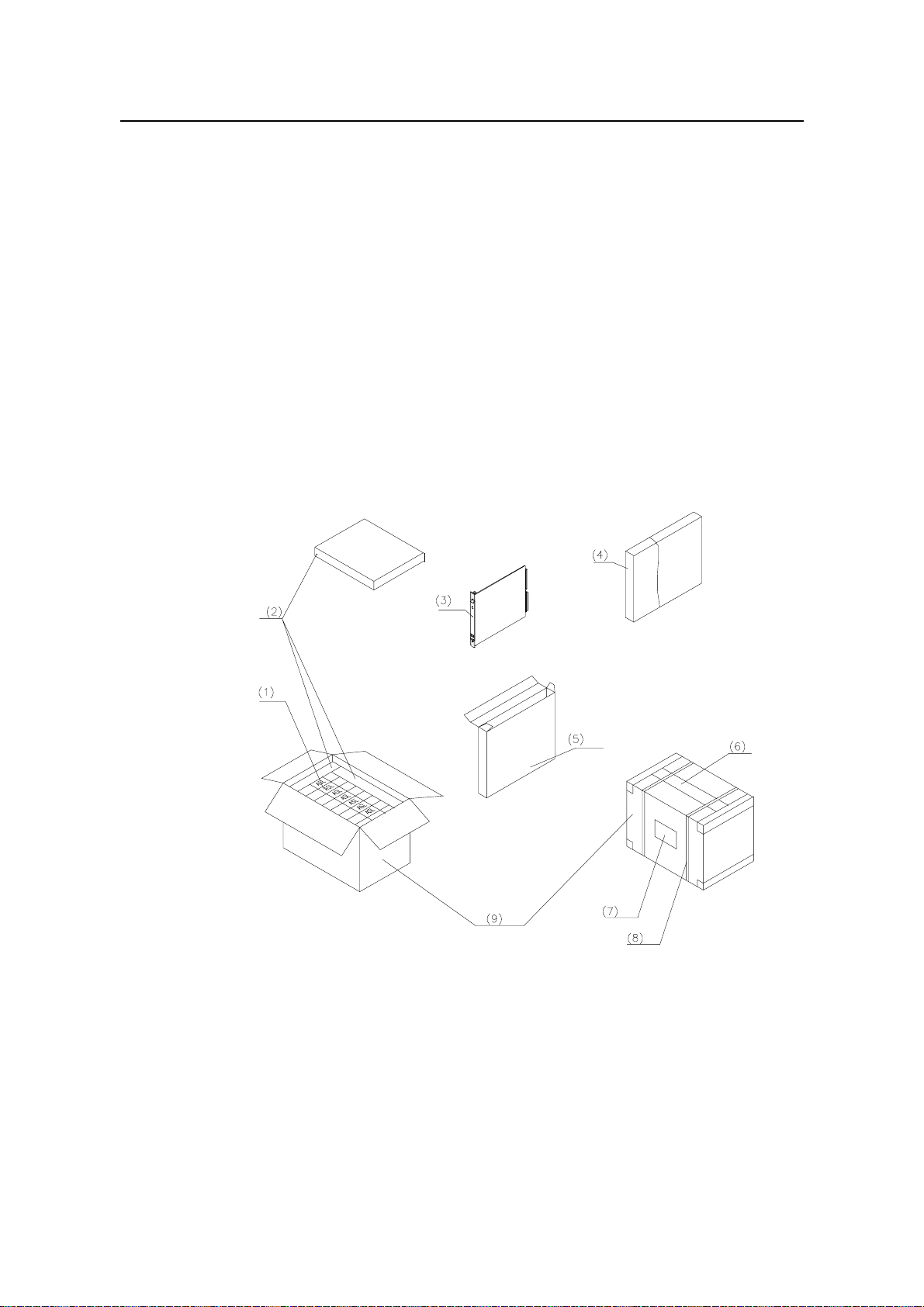
1.4.3 Unpacking Carton
Cartons are usually used to pack cables, circuit boards and terminal devices. During
transportation, these circuit boards are usually put in anti-static bags. When unpacking
the circuit boards, you need to take anti-static measures to avoid any damage to these
boards.
Meanwhile, pay attention to the temperature and humidity of the environment. To keep
the anti-static bag dry, you need to put desiccant in the bags so that it can absorb
moisture in the bags. After transporting the equipment to a place with higher
temperature and humidity, do not unpack it immediately until 30 minutes later.
Huawei Technologies Proprietary
1-9
Page 26
Installation Manual – BTS3606A Cabinet Installation
Airbridge BTS3606&3606A CDMA Base Station Chapter 1 Installation Preparations
Otherwise, moisture will condense on the surface of the eq uipment, causing damage to
it.
To open a carton, proceed as follows:
1) Check the types and quantity of boards inside the carton according to labels.
2) Cut the straps using diagonal pliers.
3) Cut the tapes along the seams of the carton cover using a knife. To avoid
damaging equipment inside, do not apply too much force.
4) Open the carton and take out the foam materials.
5) View the labels of boards, and check whether the number of boards is consistent
with what is specified on the label of the carton. Then, take out the boards.
6) Check the number and type of boards against the Packing List, and then accept
them.
Figure 1-6 shows a carton packed with boards.
(1) Board label (2) Foam materials (3) Boards (4) Anti-static bag
(5) Board box (6) Pressure-sensitive Adhesive Tape (7) Carton label
(8) Strap (9) Carton
Figure 1-6 Carton packed with boards
Huawei Technologies Proprietary
1-10
Page 27
Installation Manual – BTS3606A Cabinet Installation
Airbridge BTS3606&3606A CDMA Base Station Chapter 2 Installing Cabinet Base or Channel Steel
Chapter 2 Installing Cabinet Base or Channel Steel
The BTS3606A is outdoor equipment. When it weights more than 800 kg, it must be
installed on a cabinet base. When it weights less than 800 kg, it is installed on the
channel steel.
This chapter introduces how to install the cabinet base and channel steel.
2.1 Introduction to Cabinet Base
The cabinet is mounted on the cement plinth with the help of the cabinet base. The
cabinet base also facilitates the cabling and keeps the rodent outside the cabinet.
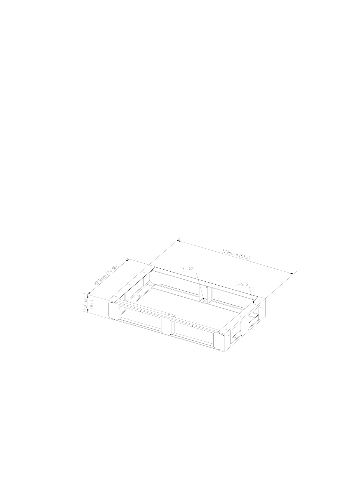
2.1.1 Base for BTS3606A Cabinet
Figure 2-1 shows the outline and dimensions of the base. The base is made up of
channel-section steel of 200 mm (8 in.) high. For the convenience of cabling, the
channel-section steel is designed with square outlets.
Figure 2-1 Outline and dimensions of the base for the BTS3606A cabinet
2.1.2 Base for Battery Cabinet
Figure 2-2 shows the outline and dimensions of the base. For the detailed
specifications of the base, see section 2.1.1 “Base for BTS3606A Cabinet”.
Huawei Technologies Proprietary
2-1
Page 28

Installation Manual – BTS3606A Cabinet Installation
Airbridge BTS3606&3606A CDMA Base Station Chapter 2 Installing Cabinet Base or Channel Steel
88 mm
(3.465 inches)
362 mm
(14.252 inches)
362 mm
(37.008 inches)
200 mm
(7.874 inches)
940 mm
(14.252 inches)
Figure 2-2 Outline and dimensions of the base for the battery cabinet
2.2 Installation Flowchart
73 mm
(2.874 inches)
10-φ12
916 mm (36.063 inches)
822 mm (32.362 inches)
856 mm (33.701 inches)
6-M12
282 mm (11.102 inches)
282 mm (11.102 inches)
282 mm (11.102 inches)
47 mm
(1.850 inches)
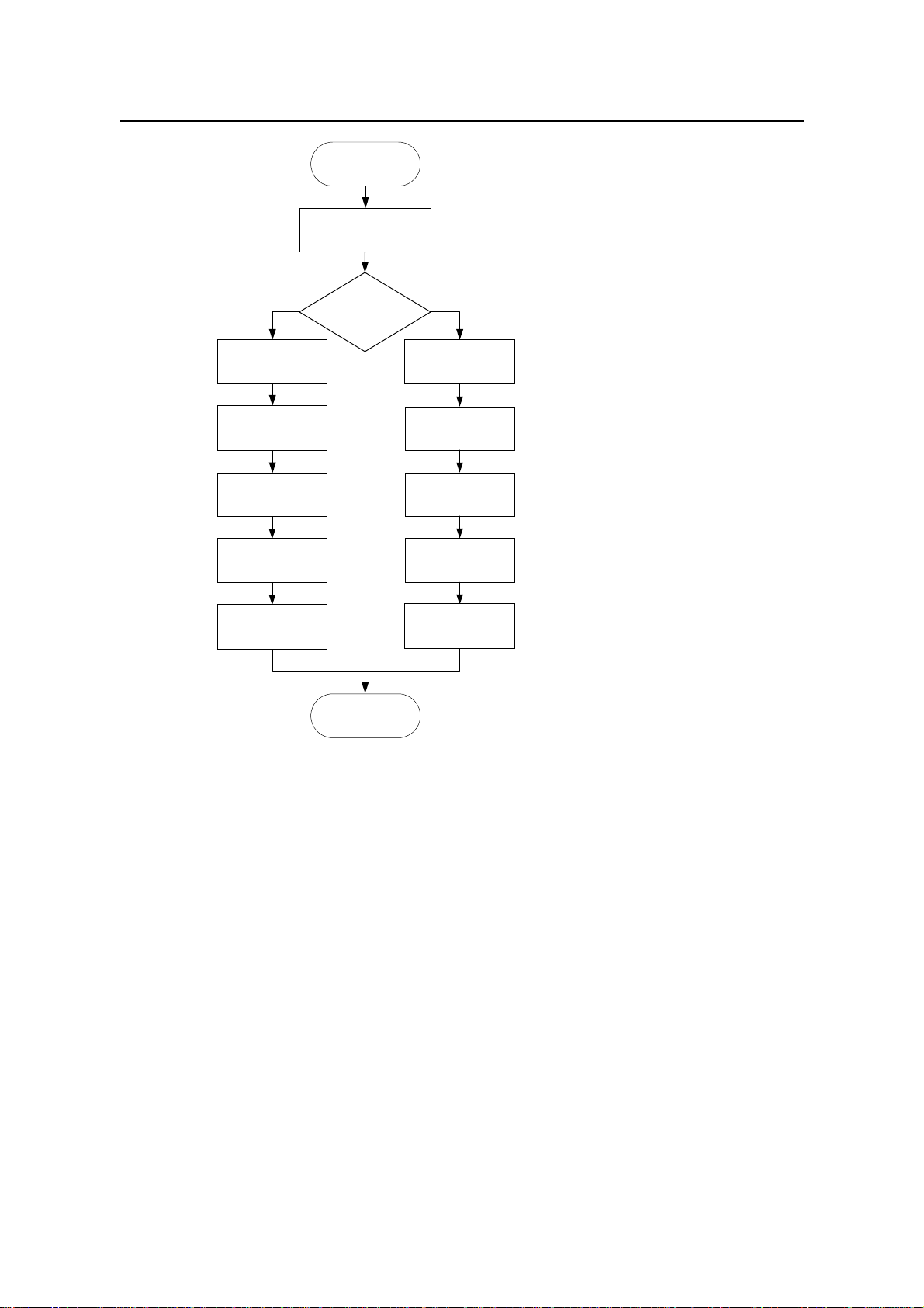
Figure 2-3 illustrates the installation procedure.
Huawei Technologies Proprietary
2-2
Page 29
Installation Manual – BTS3606A Cabinet Installation
Airbridge BTS3606&3606A CDMA Base Station Chapter 2 Installing Cabinet Base or Channel Steel
Start
Lay out the
installation position
Does the cabinet
Y
weight less than
800 kg?
Cast two cement
plinths
Prepare the
channel steel
Position the
channel steel
Drill holes and install
expansion bolts
Fasten the
channel steel
End
Cast a cement plinth
Position the base
expansion bolts
Fasten the base
Figure 2-3 Installation flowchart
N
Drill holes
Install
2.3 Installing Cabinet Base
This section introduces the procedure of installing a cabinet base, including:
Laying out installation position
z
Casting cement plinth
z
Positioning the base
z
Drilling holes and installing expansion bolts
z
Fastening the base
z
2.3.1 Laying Out Installation Position
The layout of the BTS3606A cabinet varies with the configuration. The following shows
the installation position of the BTS3606A cabinet in the following two cases:
When only one BTS3606A cabinet is installed.
z
When the BTS3606A cabinet is configured with a battery cabinet.
z
Huawei Technologies Proprietary
2-3
Page 30
Installation Manual – BTS3606A Cabinet Installation
Airbridge BTS3606&3606A CDMA Base Station Chapter 2 Installing Cabinet Base or Channel Steel
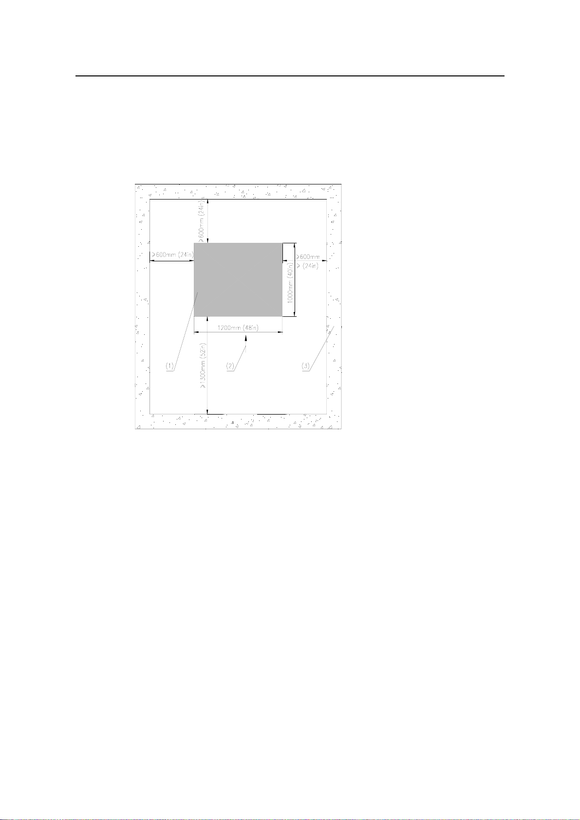
I. When There Is Only One BTS3606A Cabinet
When there is only one BTS3606A cabinet, install it according to Figure 2-4 to facilitate
the installation and maintenance. The right side of the cabinet can be placed against
the wall. It is recommended the distance be larger than 600 mm (24 in.).
To minimize the solar radiation, make sure that the front door faces the south or north.
(1) Cabinet (2) Front of the cabinet (3) Wall or other reference objects
Figure 2-4 Installation position for a BTS3606A cabinet
II. When the BTS3606A Is Configured with a Battery Cabinet
When the BTS3606A is configured with a battery cabinet, install the battery cabinet in
the position as shown in Figure 2-5 to facilitate the installation and maintenance.
You need to place the battery cabinet in the same direction with the BTS3606A cabinet,
and align it with the BTS3606A cabinet.
Huawei Technologies Proprietary
2-4
Page 31

Installation Manual – BTS3606A Cabinet Installation
Airbridge BTS3606&3606A CDMA Base Station Chapter 2 Installing Cabinet Base or Channel Steel
600mm (24in)
1000mm (40in)
(1) Battery cabinet (2) Front of battery cabinet
(3) BTS3606A cabinet (4) Wall or other reference objects
800mm (32in)
400mm (16in)
Figure 2-5 Installation position for a battery cabinet
2.3.2 Casting Cement Plinth
This section introduces how to cast cement plinth in different situations.
I. Casting Cement Plinth for a Single Cabinet
Cast the cement plinth as shown in Figure 2-6. The height of the cement plinth must
meet the flood-protection requirement in local area. The plinth must be at least 100 mm
(4 in.) higher than the ground surface and protect the cabinet against water penetration
in the case of heavy rain or flood.
When casting the plinth, make sure that its level error is no more than 5 mm (0.2 in.).
Huawei Technologies Proprietary
2-5
Page 32

Installation Manual – BTS3606A Cabinet Installation
Airbridge BTS3606&3606A CDMA Base Station Chapter 2 Installing Cabinet Base or Channel Steel
Figure 2-6 Dimensions of a cement plinth
II. Casting Cement Plinth When a Battery Cabinet Is Configured
During the installation of the BTS3606A cabinet, the cement plinth is cast according to
the outline and dimensions shown in Figure 2-7. Space for installing a battery cabinet is
reserved on the cement plinth.
If a battery cabinet is added due to capacity expansion, a new cement plinth will be cast.
Figure 2-7 shows the total dimensions of cement plinths for battery cabinet and
BTS3606A cabinet. Note that two plinths must be at the same level.
Figure 2-7 Dimensions of cement plinth for battery cabinet and BTS3606A cabinet
2.3.3 Positioning the Base
To position the base, proceed as follows:
1) Determine the installation position based on the predefined benchmark
dimensions in project plane design.
2) Use a measuring tape to measure off the scribing points.
3) Mark out the installation holes one by one as designed.
4) Measure the distance between holes again.
Figure 2-8 illustrates the installation holes of expansion bolts during the installation of a
BTS3606A cabinet.
Huawei Technologies Proprietary
2-6
Page 33

Installation Manual – BTS3606A Cabinet Installation
Airbridge BTS3606&3606A CDMA Base Station Chapter 2 Installing Cabinet Base or Channel Steel
(1) Cement plinth (2) Outline of the cabinet
(3) Installation hole of the expansion bolt (4) Front of the cabinet
Figure 2-8 Layout and dimensions of installation holes for a BTS3606A cabinet
Figure 2-9 illustrates the installation holes of expansion bolts when a battery cabinet is
configured.
Huawei Technologies Proprietary
2-7
Page 34

Installation Manual – BTS3606A Cabinet Installation
Airbridge BTS3606&3606A CDMA Base Station Chapter 2 Installing Cabinet Base or Channel Steel
(1) Cement plinth (2) Outline of the battery cabinet
(3) Installation hole of the expansion bolt (4) Position of the BTS3606A cabinet
(5) Front of the cabinet
Figure 2-9 Layout of installation holes when a battery cabinet is configured
2.3.4 Drilling Holes and Installing Expansion Bolts
Caution:
Bury the upper side of expansion tube in the ground. Otherwise, the cabinet may not
z
be able to sit firmly on the ground.
The depth of the hole must range from 52 mm (2.08 in.) to 60 mm (2.4 in.) (the
z
length of the expansion tube plus that of the drill bit). Otherwise, the expansion bolt
cannot be fastened.
All holes must have the same depth. Before measuring the depth of the hole,
z
remove the dust inside the hole to measure the net depth.
If the floor is too hard and smooth to settle the drill bit, punch a pit with a chisel to
z
help position the hole.
To drill holes and install expansion bolts, proceed as follows:
Huawei Technologies Proprietary
2-8
Page 35

Installation Manual – BTS3606A Cabinet Installation
Airbridge BTS3606&3606A CDMA Base Station Chapter 2 Installing Cabinet Base or Channel Steel
1) Use the M12 expansion bolt and φ16 bit.
2) Hold the drill stock firmly with two hands, and keep the drill bit vertical to the
ground to drill a hole.
3) Clean the dust with a vacuum cleaner when drilling.
4) Disassemble the expansion bolt and remove the M12 x 70 bolt, spring washer,
and plain washer, as shown in Figure 2-10.
(1) M12 x 70 bolt (2) Spring washer (3) Plain washer
(4) Expansion tube (5) Guiding slot (6) Nut
(7) Guiding rib
Figure 2-10 Disassembling expansion bolts
5) Feed the tube and the nut into the hole vertically and make sure that the guiding rib
on the nut meets the guiding slot of the tube. See Figure 2-11.
6) Hammer the tube until it is completely buried in the ground.
Figure 2-11 Installing the expansion bolt and expansion tube
Huawei Technologies Proprietary
2-9
Page 36

Installation Manual – BTS3606A Cabinet Installation
Airbridge BTS3606&3606A CDMA Base Station Chapter 2 Installing Cabinet Base or Channel Steel
2.3.5 Fastening the Base
To fasten the base, proceed as follows:
1) Disassemble the cabling rack, rodent-resistant plate and anti-slip plate.
2) Put the base on the cement plinth.
3) Match the holes at the bottom of the base with those on the plinth.
4) Level the cabinet by adding washers under the base.
5) Fasten the base on the plinth using M12 x 70 bolts, spring washer, big plain
washer, and square taper washer.
The fastening base of BTS3606A cabinet is shown in Figure 2-12, and that of
battery cabinet is shown in Figure 2-13.
(1) Cement plinth (2) Base (3) Washer (4) Square taper washer 12
(5) Big plain washer 12 (6) Spring washer 12 (7) M12 x 70 bolt
Figure 2-12 Fastening the base of BTS3606A
Huawei Technologies Proprietary
2-10
Page 37

Installation Manual – BTS3606A Cabinet Installation
Airbridge BTS3606&3606A CDMA Base Station Chapter 2 Installing Cabinet Base or Channel Steel
(1) Cement plinth (2) Base (3) Washer (4) Square taper washer 12
(5) Big plain washer 12 (6) Spring washer 12 (7) M12 x 70 bolt
Figure 2-13 Fastening the base of battery cabinet
2.4 Installing Channel Steel
This section introduces the procedure of installing the channel steel, including:
Laying out installation position
z
Casting cement plinths
z
Preparing the channel steel
z
Positioning the channel steel
z
Drilling holes and installing expansion bolts
z
Fastening the channel steel
z
Note:
The cross section of the channel steel must be 200 mm (7.87 in.) x 73 mm (2.87 in.) x 7
mm (0.28 in.).
If the equipment is installed inside a building or on the top of a building, the bearing
capacity of the building must be verified according to the weight and installation
position of the equipment. If the bearing capacity is insufficient, reinforce the building.
Huawei Technologies Proprietary
2-11
Page 38

Installation Manual – BTS3606A Cabinet Installation
Airbridge BTS3606&3606A CDMA Base Station Chapter 2 Installing Cabinet Base or Channel Steel
2.4.1 Laying out Installation Position
For details, see section 2.3.1 "Laying Out Installation Position".
2.4.2 Casting Cement Plinths
Determine the position of the wall or beam that bears the BTS3606A. Then cast two
cement plinths on the floor or platform right above the bearing wall or the beam.
The cement plinth must be 100 mm in height and the distance between two cement
plinths must be less than 6 m.
2.4.3 Preparing Channel Steel
Determine the length of channel steel according to the distance between cement
plinths, as shown in Figure 2-14
Figure 2-14 Preparing channel steel
2.4.4 Positioning Channel Steel
Drill twenty four Φ16 holes on the channel steel according to Figure 2-14.
2.4.5 Drilling Holes and Installing Expansion Bolts
For instructions on drilling holes and installing expansion bolts, see section 2.3.4
"Drilling Holes and Installing Expansion Bolts".
2.4.6 Fastening Channel Steel
Use one of the following methods to secure the channel steel on the cement plinths:
Huawei Technologies Proprietary
2-12
Page 39

Installation Manual – BTS3606A Cabinet Installation
Airbridge BTS3606&3606A CDMA Base Station Chapter 2 Installing Cabinet Base or Channel Steel
Cast the channel steel and the cement plinths together with cement.
z
Fasten the channel steel on the cement plinths with expansion bolts.
z
After the channel steel are fastened, measure the upper levels of the three pieces of
channel steel and make sure their upper levels are on the same plane.
Huawei Technologies Proprietary
2-13
Page 40

Installation Manual – BTS3606A Cabinet Installation
Airbridge BTS3606&3606A CDMA Base Station Chapter 3 Installing Cabinet and Cabinet Equipment
Chapter 3 Installing Cabinet and Cabinet
Equipment
This chapter introduces how to install the BTS3606A cabinet, the battery cabinet, and
the equipment inside these cabinets.
3.1 Installation of Cabinet
During the installation of combined cabinets, the extension cabinet is installed in the
same way as the basic cabinet.
To install the basic cabinet, proceed as follows:
1) Position the cabinet.
2) Level the cabinet.
3) Fasten the cabinet.
4) Install accessories.
3.1.1 Positioning Cabinet
Lift and place slowly the cabinet over the base and align the installation holes on the
bottom of the cabinet with those on the base.
Caution:
An empty cabinet weighs 450 kg (992 lb.). Confirm the lifting capability of the lifting
z
equipment beforehand.
When lifting the cabinet, make sure that all the four lugs are reliably hooked, the
z
angle between the lifting rope and the top of the cabinet is at least 60
cabinet is level. Installers must stay away from the cabinet when lifting it and make
sure that the front and rear doors are closed.
When installing the cabinet in bad conditions (for example, when there is strong
z
wind), pay extra attention to the gravity center of the cabinet to prevent the cabinet
from slanting.
o
, and the
If the cabinet cannot be lifted on site, position the cabinet according to the bearing
points shown in Figure 3-1 and site characteristics.
Huawei Technologies Proprietary
3-1
Page 41

Installation Manual – BTS3606A Cabinet Installation
Airbridge BTS3606&3606A CDMA Base Station Chapter 3 Installing Cabinet and Cabinet Equipment
(1) Lug (2) Mount angle
Figure 3-1 Cabinet bearing points
3.1.2 Leveling Cabinet
To level the cabinet, proceed as follows:
1) Use a level bar to check the levelness of the cabinet in both the latitudinal and
longitudinal directions.
2) Observe whether the level vial is in the middle of the level bar.
If there is no error, fasten the cabinet by following the instructions in section
z
3.1.3 "Fastening Cabinet".
If an error exists, lift the cabinet.
z
3) Adjust the levelness by adding washers between the cabinet and base, as shown
in Figure 3-2 and Figure 3-3.
Huawei Technologies Proprietary
3-2
Page 42

Installation Manual – BTS3606A Cabinet Installation
Airbridge BTS3606&3606A CDMA Base Station Chapter 3 Installing Cabinet and Cabinet Equipment
(1) Cement plinth (2) Base (3) Cabinet (4) M12 x 35 bolt
(5) Plain washer 12 (6) Spring washer 12 (7) Washer
Figure 3-2 Leveling a BTS3606A cabinet (Installing cabinet on base)
(2)(3)
(1)
(4)
(5)
(6)
(7)
(8)
(9)
(1) Cabinet (2) Channel steel (3) cement plinths
(4) M12x40 bolt (5) Spring washer 12 (6) Plain washer 12
(7) Washer (8) Square taper washer 12 (9) M12 nut
Figure 3-3 Leveling a BTS3606A cabinet (Installing cabinet on channel steel)
Huawei Technologies Proprietary
3-3
Page 43

Installation Manual – BTS3606A Cabinet Installation
Airbridge BTS3606&3606A CDMA Base Station Chapter 3 Installing Cabinet and Cabinet Equipment
3.1.3 Fastening Cabinet
Note:
Do not open the front door unless it is ensured that the cabinet is level.
z
z If the front door keeps open for a long time, use a solid object to support the lower
part of the door to prevent the deformation of the door.
Before you close the front door, lift the support bar and slide it along the rail.
z
To fasten the cabinet, proceed as follows:
1) Fasten the cabinet on the base using M12 x 35 bolts, spring washers, and plain
washers, as shown in Figure 3-2.
2) Unlock and open the door as shown in Figure 3-4.
Figure 3-4 Opening the front door
3) Fix the front door at a suitable angle with the support bar on the top of the door.
Huawei Technologies Proprietary
3-4
Page 44

Installation Manual – BTS3606A Cabinet Installation
Airbridge BTS3606&3606A CDMA Base Station Chapter 3 Installing Cabinet and Cabinet Equipment
Note:
The front door can be fully opened to 120o.
z
The support bar can be fixed at an angle of 90o or 120o.
z
4) Fix one end of the bar on the rail with a fixing bolt as shown in Figure 3-5.
The other end of the bar is fixed on the cabinet with a screw.
(1) Support bar (2) Fixing bolt
Figure 3-5 Fixing the front door
5) Assemble an M12 x 100 bolt with spring washer 12 and plain washer 12.
6) Install the assembled burglary-resisting bolt. See Figure 3-6.
Huawei Technologies Proprietary
3-5
Page 45

Installation Manual – BTS3606A Cabinet Installation
Airbridge BTS3606&3606A CDMA Base Station Chapter 3 Installing Cabinet and Cabinet Equipment
(1) Base (2) Cabinet (3) M12 x 100 bolt
(4) Spring washer 12 (5) Plain washer
Figure 3-6 Installing the burglary-resisting bolt
Note:
Step 6 applies to the installation of BTS3606A cabinet on a base only.
3.1.4 Installing Accessories
Note:
This section is applies to the installation of BTS3606A cabinet on a base only.
To install accessories including a cabling rack and a rodent-resistant plate, proc eed as
follows:
1) Position the cabling rack according to the cable outlet.
2) Mount the cabling rack on the base using M8 x 12 screws, as shown in Figure 3-7.
Huawei Technologies Proprietary
3-6
Page 46

Installation Manual – BTS3606A Cabinet Installation
Airbridge BTS3606&3606A CDMA Base Station Chapter 3 Installing Cabinet and Cabinet Equipment
(1) Base (2) M8x20 screw (3) Cabling rack
Figure 3-7 Mounting cabling rack
3) On the rodent-resistant plate, cut an opening where the cable is led out or led in
according to the shape of cables.
4) Mount the rodent-resistant plate on the base using M6 x 12 screws, as shown in
Figure 3-8.
Huawei Technologies Proprietary
3-7
Page 47

Installation Manual – BTS3606A Cabinet Installation
Airbridge BTS3606&3606A CDMA Base Station Chapter 3 Installing Cabinet and Cabinet Equipment
(1) Base (2) Rodent-resistant plate (3) M6 x 12 screw (4) Lug
Figure 3-8 Mounting the rodent-resistant plate
3.1.5 Removing Lugs (Optional)
After the cabinet is installed, remove the lugs. Use nylon gaskets and bolts delivered
with the equipment to fill the holes on the lugs and then keep the lugs in the tool box.
3.2 Installation of Auxiliary Battery Cabinet
The auxiliary battery cabinet is installed in the same method as the BTS3606A cabinet.
The following presents the reference and details the differen ces.
3.2.1 Positioning Cabinet
See section 3.1.1 “Positioning Cabinet”.
Caution:
An empty cabinet weighs 300 kg (662 lb.). Confirm the lifting capability of the lifting
equipment beforehand.
Huawei Technologies Proprietary
3-8
Page 48

Installation Manual – BTS3606A Cabinet Installation
Airbridge BTS3606&3606A CDMA Base Station Chapter 3 Installing Cabinet and Cabinet Equipment
3.2.2 Leveling Cabinet
See section 3.1.2 “Leveling Cabinet”.
Figure 3-9 shows how to level the cabinet.
(1) Cement plinth (2) Base (3) Cabinet (4) Washer
(5) Plain washer 12 (6) Spring washer 12 (7) M12x35 bolt
Figure 3-9 Leveling a cabinet (battery cabinet)
3.2.3 Fastening Cabinet
See section 3.1.3 “Fastening Cabinet”.
3.2.4 Installing Accessories
The accessories of the battery cabinet also include cabling rack, anti-slip plate, and
rodent-resistant plate. To install them, see section 3.1.4 “Installing Accessories”.
Figure 3-10 shows how to mount the cabling rack.
Huawei Technologies Proprietary
3-9
Page 49

Installation Manual – BTS3606A Cabinet Installation
Airbridge BTS3606&3606A CDMA Base Station Chapter 3 Installing Cabinet and Cabinet Equipment
(1) Base (2) M8x20 screw (3) Cabling rack
Figure 3-10 Mounting the cabling rack
Figure 3-11 shows how to mount the rodent-resistant plate.
(1) Base (2) Rodent-resistant plate (3) M6 x 12 screw (4) Lug
Figure 3-11 Mounting rodent-resistant plate
Huawei Technologies Proprietary
3-10
Page 50

Installation Manual – BTS3606A Cabinet Installation
Airbridge BTS3606&3606A CDMA Base Station Chapter 3 Installing Cabinet and Cabinet Equipment
3.2.5 Removing Lugs
After the cabinet is installed, remove the lugs. Use the filler blocks delivered with the
equipment to fill the holes on the lugs and then keep the lugs in the tool box.
3.3 Installation and Removal of BTS3606A Cabinet Front
Door
The front and rear doors of the BTS3606A cabinet have been installed before delivery.
The following describes how to remove cabinet doors. You can follow the reverse order
to install the doors.
3.3.1 Removing Front Door
Caution:
The front door is large and heavy. You need lifting equipment such as a lifting jack to
z
install or remove it.
Avoid tipping over the front door when installing or removing the front door.
z
Accidents may result.
The air-conditioner is attached inside the front door. Therefore, never put the front
z
door flatly on the ground during the installation or removal.
Make sure the angle between the vertical plane and the front door is laid vertical or
z
the slope angle is less than 20°.
To remove the front door, proceed as follows:
1) Remove all the cables and hinges on the front door.
2) Remove the bolts of the support bar on the front door.
3) Lift the support bar from the rail on the front door.
4) Remove the circlip on the latch.
5) Lift the front door lightly using the lifting equipment.
6) Remove the latch from the side of the front door.
7) Lift the front door vertically.
3.3.2 Removing Rear Door
The rear door of the cabinet is normally not removed during the routine maintenance.
But if the cabinet cannot be lifted, remove the rear door to reduce the weight of the
cabinet for transportation.
Huawei Technologies Proprietary
3-11
Page 51

Installation Manual – BTS3606A Cabinet Installation
Airbridge BTS3606&3606A CDMA Base Station Chapter 3 Installing Cabinet and Cabinet Equipment
Caution:
Disconnect all the cables on the rear door before removing the rear door.
To remove the rear door of the BTS3606A, proceed as follows:
1) Use the dedicated spanner attached to the BTS3606A cabinet to remove the M6
screws on the rear door.
2) Remove the rear door slowly.
3.4 Installation of Cabinet Equipment
Caution:
Insert the boards according to the nameplates to avoid any mistake.
z
Avoid touching printed circuit boards (PCBs) and components other than jumpers
z
and DIP switches.
Insert the board vertically and gently lest the pins and components on the backplane
z
be damaged.
Before installing boards and modules, check the DIP switches on the backplane or
boards are correctly set. For example, make sure the DIP switch on the BCIM is
correctly set according to the silk-screen before installing the board.
When a dummy panel is installed on the slot, unscrew the bolts and remove the dummy
panel before installing the board. It is recommended to remove a dummy panel at a
time and then install a board accordingly.
3.4.1 Installing Boards in Baseband Subrack
Baseband boards include the CCPM/CECM, BCIM, and BCKM.
Note:
Slots for the channel processing boards are marked as CEM. The CEM can be a
CCPM or a CECM.
To install the boards in the baseband subrack, proceed as follows:
1) Check the cleanness of the subracks and clean them up.
Huawei Technologies Proprietary
3-12
Page 52

Installation Manual – BTS3606A Cabinet Installation
Airbridge BTS3606&3606A CDMA Base Station Chapter 3 Installing Cabinet and Cabinet Equipment
2) Wear an antistatic wrist strap and ground it by inserting its grounding plug to the
antistatic jack on the side door post of the cabinet.
3) Check whether there are any tilted, missing or broken pins on the backplane.
z If any pin is tilted, straighten it. Use the sharp-nose pliers to straighten pins in
the case of emergency.
If any pin is missing or broken, replace the backplane.
z
4) Make sure the ejector levers on the front panel are in the state as shown in
Figure 3-12.
Figure 3-12 Installing a board (1)
5) Hold the upper ejector lever on the front panel with one hand and uplift the board
with the other. With reference to the name on the nameplate, put the board on the
corresponding guide rail.
6) Hold the two ejector levers and insert the board along the guide rail gently till it is
in position.
7) Turn the two ejector levers towards the middle of the panel simultaneously to fix
the board. See Figure 3-13.
Huawei Technologies Proprietary
3-13
Page 53

Installation Manual – BTS3606A Cabinet Installation
Airbridge BTS3606&3606A CDMA Base Station Chapter 3 Installing Cabinet and Cabinet Equipment
Figure 3-13 Installing a board (2)
8) Tighten the screws clockwise on the front panel. See Figure 3-14.
Figure 3-14 Installing a board (3)
3.4.2 Installing Modules in RF Subrack
Modules in the RF subrack include CCDU, CTRM/CMTR, CMPA/CHPA. Their
installation procedures are similar.
Caution:
The transmit and receive performance of the BTS may degrade if the screws are
fastened before the CTRM/CMTR, CDDU, and other RF modules are placed in
position.
To install a module in the RF subrack, proceed as follows:
Huawei Technologies Proprietary
3-14
Page 54

Installation Manual – BTS3606A Cabinet Installation
Airbridge BTS3606&3606A CDMA Base Station Chapter 3 Installing Cabinet and Cabinet Equipment
1) Check the cleanness of the subrack and clean it up.
2) Wear the antistatic wrist strap.
3) Align the RF module with the relevant subrack.
4) Insert the module gently along the corresponding guide rail until resistance is felt.
5) Fasten all screws onto the panel one by one and ensure that the module panel is
in seamless contact with the cabinet subrack.
6) Mount the RF fan module onto the front panel of the RF module.
7) Fasten the screws appropriately on the front panel of the RF fan module.
Note:
The modules are removed in the reverse order of installing them.
3.4.3 Installing Power Module
The power module includes DC/DC unit, AC/DC unit and PMU. Their installation
procedures are similar.
To install a power module, proceed as follows:
1) Clean up the cabinet and the subrack.
2) Wear the antistatic wrist strap.
3) Remove the dummy panel.
4) Align the board with the corresponding guide rail according to the board name on
the nameplate.
5) Insert the board along the corresponding guide rail until resistance is felt.
6) Tighten the captive screws on the panel.
Note:
Upon the installation of the PSU
z
used. Turn the anti-slip lock on the panel to a side with the lock icon to fix PSU
The upper and lower subracks must have the same number of PSU
z
, an anti-slip lock instead of captive screws is
AC/DC
modules no
AC/DC
AC/DC
matter whether the power supply is the three-phase or single-phase one.
Never tighten the captive screw by force if it is too tight to screw down. If necessary,
z
reinstall the module and align the mounting holes in the module with those in the
subrack.
.
Huawei Technologies Proprietary
3-15
Page 55

Installation Manual – BTS3606A Cabinet Installation
Airbridge BTS3606&3606A CDMA Base Station Chapter 3 Installing Cabinet and Cabinet Equipment
3.4.4 Installing Built-in Batteries
The built-in batteries are installed after the batteries are connected with each oth er . For
installation method, see section 5.10, “Installing Built-in Batteries".
Note:
If the battery power is available, built-in batteries can be spared.
3.4.5 Installing Built-in Transmission Equipment
The BTS3606A can employ transmission modes such as SDH, HDSL, microwave, or
E1/T1. In addition to E1 transmission mode compliant with G.703 standard, it also
provides space and interfaces for built-in transmission equipment. You can install the
transmission equipment as needed.
The BTS3606A cabinet must meet the following requirements:
The reserved space in the cabinet is 19 in. wide, 6 U high, and 600 mm (24 in.)
z
deep. (1 U = 44.45 mm, IEC297)
The cable outlets are also reserved for cables of microwave, SDH, and E1
z
equipment.
The BTS3606A can provide –48 V DC power for the transmission equipment.
z
3.5 Installation or Removal of Auxiliary Battery Cabinet
Doors
The front and rear doors of the auxiliary battery cabinet have been installed before
delivery. During the installation and maintenance of the cabinet, it is not necessary to
reinstall the rear door.
The following introduces how to open the front door and how to remove the rear door.
The installation procedures of the rear door are reverse of the removal procedures.
After finishing the installation, turn the burglary-resisting handle back to the original
position.
3.5.1 Opening the Front Door
Caution:
Before closing the door, lift and slide the support bar along the rail.
Huawei Technologies Proprietary
3-16
Page 56

Installation Manual – BTS3606A Cabinet Installation
Airbridge BTS3606&3606A CDMA Base Station Chapter 3 Installing Cabinet and Cabinet Equipment
To open the front door, proceed as follows:
1) Unlock the door with the key.
2) Pull the handle outwards to open the door.
3) Move the support bar along a rail to the end.
4) Fasten the front door.
3.5.2 Removing the Rear Door
To remove the rear door, proceed as follows:
1) Rotate burglary-resisting handle from the front door to unlock the rear door, as
shown in Figure 3-15.
(1) Lock of the rear door
Figure 3-15 Unlocking the rear door
2) Unscrew the four M6 bolts on the panel of the rear door.
3) Put aside the bolts.
4) Remove the rear door.
Huawei Technologies Proprietary
3-17
Page 57

Installation Manual – BTS3606A Cabinet Installation
Airbridge BTS3606&3606A CDMA Base Station Chapter 3 Installing Cabinet and Cabinet Equipment
3.6 Installation of Batteries in Auxiliary Battery Cabinet
Caution:
Arrange the batteries according to the positive and negative terminals as shown in
Figure 3-16. Otherwise, it is possible that the battery cables cannot be connected
properly.
+- +-+-
-+ -+
+- +- +-
-+ -+ -+
(1) Front view (2) Rear view
-+
(1)
+- +-+-
-+ -+
+- +- +-
-+ -+ -+
-+
(2)
Figure 3-16 Installing batteries
To install batteries in an auxiliary battery cabinet, proceed as follows:
1) Remove the baffle plates in front of each battery subrack, as shown in Figure 3-17.
Huawei Technologies Proprietary
3-18
Page 58

Installation Manual – BTS3606A Cabinet Installation
Airbridge BTS3606&3606A CDMA Base Station Chapter 3 Installing Cabinet and Cabinet Equipment
(1) Baffle plate
Figure 3-17 Removing baffle plates
2) Put the batteries into the cabinet. Be sure that the side of the battery with
connecting terminals must face outward.
3) Install the baffle plates in front of the subrack to prevent the batteries from falling
down.
3.7 Illustration of Cabinets After Installed on Cement Plinth
Figure 3-18 illustrates the BTS3606A cabinet after it is installed on the cement plinth.
Huawei Technologies Proprietary
3-19
Page 59

Installation Manual – BTS3606A Cabinet Installation
Airbridge BTS3606&3606A CDMA Base Station Chapter 3 Installing Cabinet and Cabinet Equipment
Figure 3-18 BTS3606A cabinet installed on cement plinth
Figure 3-19 illustrates the auxiliary battery cabinet after it is installed on the cement
plinth.
Huawei Technologies Proprietary
3-20
Page 60

Installation Manual – BTS3606A Cabinet Installation
Airbridge BTS3606&3606A CDMA Base Station Chapter 3 Installing Cabinet and Cabinet Equipment
Figure 3-19 Auxiliary battery cabinet installed on cement plinth
Huawei Technologies Proprietary
3-21
Page 61

Installation Manual – BTS3606A Cabinet Installation
Airbridge BTS3606&3606A CDMA Base Station
Chapter 4 Installing Outdoor Transmission and
Power Interface Boxes
Chapter 4 Installing Outdoor Transmission and
Power Interface Boxes
This chapter introduces the functional structure of the outdoo r tra nsmission and power
interface boxes and their installation procedures.
4.1 Introduction to Outdoor Transmission and Power
Interface Boxes
This section introduces the structure and components of the outdoor transmission and
power interface boxes.
4.1.1 Outdoor Transmission Interface Box
There are two types of TSI-DDF/ODF transmission interface box:
75Ω transmission interface box
z
120Ω transmission interface box
z
Figure 4-1 shows the structure of a 75Ω transmission interface box.
(1) 12-core fiber fusing and distributing assemblies
(3) Grounding busbar (4) Enclosure
Figure 4-1 Structure of 75Ω transmission interface box
Huawei Technologies Proprietary
4-1
(2) 8-E1 75ΩDDF unit
Page 62

Installation Manual – BTS3606A Cabinet Installation
Airbridge BTS3606&3606A CDMA Base Station
Figure 4-2 shows the structure of a 120Ω transmission interface box.
Chapter 4 Installing Outdoor Transmission and
Power Interface Boxes
(1) 12-core fiber fusing and distributing assemblies
(3) Grounding busbar (4) Enclosure
(2) 8-E1 120ΩDDF unit
Figure 4-2 Structure of 120Ω transmission interface box
Table 4-1 lists the specifications of the transmission interface box.
Table 4-1 Specifications of the TSI-DDF/ODF transmission interface box
Name
Dimensions (Length
x Width x Height)
Weight (in default
configuration)
TSI-DDF/ODF transmission interface box
420 mm (16.5 in.) x 378 mm (14.9 in.) x 125 mm (4.9 in.)
4.92 kg (10.85 lb.)
Enclosure
Grounding busbar
8-loop module bar (optional)
Components
75Ω DDF unit (optional)
120Ω DDF unit (optional)
12-core fiber fusing and distributing assemblies (optional)
4.1.2 Outdoor Power Interface Box
Figure 4-3 illustrates the structure of a power interface box.
Huawei Technologies Proprietary
4-2
Page 63

Installation Manual – BTS3606A Cabinet Installation
Airbridge BTS3606&3606A CDMA Base Station
(1) Enclosure (2) Mains air breaker (3) Diesel air breaker
(4) Air breaker interlock device (5) Input/output terminal bar
Figure 4-3 Internal structure of PSI power interface box
Table 4-2 lists the specifications of the power interface box.
Table 4-2 Specifications of the PSI power interface box
Chapter 4 Installing Outdoor Transmission and
Power Interface Boxes
Name
Dimensions (Length x
Width x Height)
Default configuration
Weight (in default
configuration)
PSI power interface box
420 mm (16.5 in.) x 378 mm (14.9 in.) x 125 mm (4.9 in.)
Enclosure
Mains air breaker
Input/output terminal bar
4.54 kg (10.01 lb.)
Enclosure
Mains air breaker
Components
Input/output terminal bar
Diesel air breaker assemblies (optional)
Figure 4-4 shows the default configuration of the power interface box.
Huawei Technologies Proprietary
4-3
Page 64

Installation Manual – BTS3606A Cabinet Installation
Airbridge BTS3606&3606A CDMA Base Station
Chapter 4 Installing Outdoor Transmission and
Power Interface Boxes
Figure 4-4 Default configuration of PSI power interface box
4.2 Installing Outdoor Transmission and Power Interface Box
Caution:
When installing the transmission interface box, the length of the cable between the box
and BTS3606A cabinet must be less than 7 m (240 in.).
Since TSI-DDF/ODF transmission interface box and PSI power interface box are
outdoor equipment, their enclosures can be mounted on wall or on steel pole as
needed.
The following respectively introduces how to mount the transmission interface box on
the wall and on the steel pole.
4.2.1 Mounting Transmission Interface Box on the Wall
Note:
Use the M8 expansion bolts to fasten the transmission interface box and the
percussion drill with a φ10 drill bit to drill holes.
To install the transmission interface box on the wall, proceed as follows:
1) Position the transmission interface box according to the project requirement.
2) Stick the lineate paper template delivered with the box to the wall.
3) Mark installation holes of the four expansion bolts on the wall surface, as shown in
Figure 4-5.
Huawei Technologies Proprietary
4-4
Page 65

Installation Manual – BTS3606A Cabinet Installation
Airbridge BTS3606&3606A CDMA Base Station
Figure 4-5 Installation holes of expansion bolts
Chapter 4 Installing Outdoor Transmission and
Power Interface Boxes
4) Drill holes and install expansion bolts by following the instruction in section 2.3.4
“Drilling Holes and Installing Expansion Bolts”.
5) Align the four installation holes of the transmission interface box with the
corresponding expansion bolts.
6) Lead the bolts through the corresponding holes.
7) Put plain washers, spring washers, and nuts onto the expansion bolts.
See Figure 4-6.
(1) Transmission interface box (2) Wall
(3) M8 nut (4) Spring washer 8
(5) Plain washer 8 (6) M8 x 80 expansion bolt
Figure 4-6 Mounting transmission interface box on the wall
Huawei Technologies Proprietary
4-5
Page 66

Installation Manual – BTS3606A Cabinet Installation
Airbridge BTS3606&3606A CDMA Base Station
Chapter 4 Installing Outdoor Transmission and
Power Interface Boxes
8) Adjust the location of the box.
9) Tighten the nuts to 13.4 N m (116 in. lbs).
4.2.2 Mounting Transmission Interface Box on the Steel Pole
Caution:
The outer diameter of the steel pole must range from 60 mm (2.4 in.) to 114 mm (4.5
in.).
To mount the transmission interface box on the steel pole, proceed as follows:
1) Assemble the transmission interface box and the beam using M8 x 25 bolts, spring
washers, and plain washers. See Figure 4-7.
(1) Outdoor transmission interface box (2) Beam
(3) M8 x 25 bolt (4) Spring washer 8
(5) Plain washer 8
Figure 4-7 Assembling the beam
2) Place the fixed beam and box on the steel pole.
3) Mount fasteners.
4) Lead a long M10 bolt through the beam and the fastener. See Figure 4-8.
Huawei Technologies Proprietary
4-6
Page 67

Installation Manual – BTS3606A Cabinet Installation
Airbridge BTS3606&3606A CDMA Base Station
Chapter 4 Installing Outdoor Transmission and
Power Interface Boxes
(1) Steel pole (2) Beam (3) M10 nut
(4) Plain washer 10 (5) Spring washer 10 (6) Long M10 bolt
Figure 4-8 Mounting transmission interface box on the steel pole
5) Install the plain washer, spring washer, and nut on the long bolt. See Figure 4-8.
6) Tighten the nut to 26.5 N$m (119.7 in. lbs) with a wrench.
4.3 Using Internal Components of Transmission Interface
Box
This section explains how to use:
120Ω DDF unit
z
75Ω DDF unit
z
Grounding busbar
z
12-core fiber fusing and distributing assemblies
z
Huawei Technologies Proprietary
4-7
Page 68

Installation Manual – BTS3606A Cabinet Installation
Airbridge BTS3606&3606A CDMA Base Station
4.3.1 Using 120Ω DDF Unit
To use the 120Ω DDF unit, proceed as follows:
1) Route cables to corresponding cable bands through the cabling holes on both
sides of the 120Ω DDF unit, and then connect the cables.
2) Take off the identifier board on the 120Ω DDF unit while clamping cables.
Pay attention to the difference between “a”, “b”, and “s”. The "s" is a grounding
cable.
3) After clamping cables, cover the identifier board. See Figure 4-9 and Figure 4-10.
Chapter 4 Installing Outdoor Transmission and
Power Interface Boxes
Figure 4-9 Cabling diagram after 120Ω DDF unit is installed (a)
Huawei Technologies Proprietary
4-8
Page 69

Installation Manual – BTS3606A Cabinet Installation
Airbridge BTS3606&3606A CDMA Base Station
Figure 4-10 Cabling diagram after 120Ω DDF unit is installed (b)
Chapter 4 Installing Outdoor Transmission and
Power Interface Boxes
4.3.2 Using 75Ω DDF Unit
Connect cables according to the actual requirements. Figure 4-1 1 illustrates the cabling
diagram after the installation of the 75Ω DDF unit.
Figure 4-11 Cabling diagram after 75Ω DDF unit is installed
4.3.3 Using Grounding Busbar
Figure 4-12 shows the outline of a grounding busbar.
Huawei Technologies Proprietary
4-9
Page 70

Installation Manual – BTS3606A Cabinet Installation
Airbridge BTS3606&3606A CDMA Base Station
Figure 4-12 Grounding busbar
To install the grounding busbar, proceed as follows:
1) Loosen the fastening screw on the two ends.
2) Strip the shielded cable and put it in relevant slot.
3) Fasten the screws on both ends.
4) Tighten and press the screws on the corresponding slot.
Chapter 4 Installing Outdoor Transmission and
Power Interface Boxes
4.3.4 Using 12-Core Fiber Fusing and Distributing Assemblies
Figure 4-13 shows the 12-core fiber fusing and distributing assemblies, includin g:
One optical fiber fixture
z
One 12-core optical fiber fusing box
z
One 12-core optical fiber adapter installation support
z
Two semi-circular fiber management tray
z
(1) 12-core optical fiber adapter installation support (2) 12-core optical fiber fusing box
(3) Optical fiber fixture (4) Semi-circular fiber management tray
Figure 4-13 Structure of 12-core fiber fusing and distributing assemblies
Huawei Technologies Proprietary
4-10
Page 71

Installation Manual – BTS3606A Cabinet Installation
Airbridge BTS3606&3606A CDMA Base Station
To use the 12-core fiber fusing and distributing assemblies, proceed as follows:
1) Lead the optical fiber through the waterproof locknut at the cable inlet and then
into the enclosure.
2) On the optical fiber fixture, fix and strip the optical fiber , and then gro und the core.
3) Take protective measures for the naked fiber coming out from the optical fiber
fixture, then coil it on the 12-core optical fiber fusing box, and fuse it with the tail
fiber.
4) Lead the tail fiber from the optical fiber fusing box to the cable distribution unit (that
is, 12-core optical fiber adapter installation support) to connect it with the adapter
of the cable distribution unit.
5) Lead the fiber jumper from the equipment through the fiber access saddle to the
fiber management tray and coil it.
6) Route the fiber jumper into the cable distribution unit to connect with the tail fiber,
as shown in Figure 4-14.
Chapter 4 Installing Outdoor Transmission and
Power Interface Boxes
(1) Tail fiber (2) Optical fiber (3) Fiber jumper
Figure 4-14 Cabling diagram after 12-core fiber fusing and distributing
assemblies are installed
Huawei Technologies Proprietary
4-11
Page 72

Installation Manual – BTS3606A Cabinet Installation
Airbridge BTS3606&3606A CDMA Base Station
Chapter 4 Installing Outdoor Transmission and
4.4 Installing Outdoor Power Input Components
This section explains how to install:
Diesel air breaker assemblies
z
z Grounding cable for enclosure
Input components of single-phase mains and diesel
z
Single-phase mains input components
z
Input components of three-phase mains and diesel
z
z Three-phase mains input components
4.4.1 Installing Diesel Air Breaker Assemblies
Diesel air breaker assemblies include diesel air breaker and air breaker interlock
device. When the power is supplied through a diesel, you need to install air breakers,
air breaker interlock device, and auxiliary internal connection cables on site.
Power Interface Boxes
Note:
The air breaker interlock device is designed to ensure that either of the two air breakers
is opened in any case.
To mount the diesel air breaker assemblies, proceed as follows:
1) Fasten the diesel air breaker onto the enclosure with screws. See Figure 4-15.
Figure 4-15 Mounting diesel air breaker
2) Mount the support of the air breaker interlock device onto the enclosure with
screws.
3) Lock the sliding block with locknuts. See Figure 4-16.
Huawei Technologies Proprietary
4-12
Page 73

Installation Manual – BTS3606A Cabinet Installation
Airbridge BTS3606&3606A CDMA Base Station
(1) Support (2) Gliding block (3) Screw (4) Nut
Figure 4-16 Mounting air breaker interlock device
4) Loosen locknuts.
5) Move the sliding block right and left, and adjust one air breaker until it is closed.
6) Tighten the locknuts. See Figure 4-17.
Chapter 4 Installing Outdoor Transmission and
Power Interface Boxes
4
3
2
Figure 4-17 Operating air breaker interlock device
4.4.2 Installing Grounding Cable for Enclosure
After installing power interface box, you need to ground the enclosure. Figure 4-18
illustrates the grounding point and cable bundling.
Huawei Technologies Proprietary
4-13
Page 74

Installation Manual – BTS3606A Cabinet Installation
Airbridge BTS3606&3606A CDMA Base Station
(1) Grounding nut
Chapter 4 Installing Outdoor Transmission and
Power Interface Boxes
Figure 4-18 Installing grounding cable for enclosure
4.4.3 Installing Input Components of Single-phase Mains and Diesel
Caution:
Make sure that the connection of neutral line (N) and live line (L) are correct. If they are
inversely connected, accidents may result.
To install input components of single-phase mains and diesel, proceed as follows:
1) Unpack the power interface box and the air breaker assemblies of the diesel.
2) Check that enclosure, mains air breaker, diesel air breaker, air breaker interlock
device, and input/output terminal block are all available.
3) Mount the diesel air breaker assemblies onto the enclosure by following the
instruction in section 4.4 "Installing Outdoor Power Input Components".
4) Connect the load live line to terminal A, B, or C, and the neutral line to terminal N,
as shown in Figure 4-19.
Huawei Technologies Proprietary
4-14
Page 75

Installation Manual – BTS3606A Cabinet Installation
Airbridge BTS3606&3606A CDMA Base Station
Chapter 4 Installing Outdoor Transmission and
Power Interface Boxes
(1) Mains input air breaker (2) Air breaker interlock device
(3) Single-phase diesel input air breaker (4) Connecting busbar
(5) Single-phase diesel input (6) Power output (7) Mains input
Figure 4-19 Input of single-phase mains and diesel
5) Connect the neutral line for mains input to terminal N1, and the live line to terminal
L1, as shown in Figure 4-19.
6) Connect the neutral line for diesel input to terminal N2, and the live line to terminal
L2, as shown in Figure 4-19.
4.4.4 Installing Single-phase Mains Input Components
Caution:
Make sure that the connections of neutral line (N) and live line (L) are correct. If they
are inversely connected, accident may result.
To install the single-phase mains input components, proceed as follows:
1) Unpack the power interface box.
2) Check that enclosure, mains air breaker, and input/output terminal block are all
available.
3) Connect the load live line to terminal A, B, or C, and the neutral line to terminal N,
as shown in Figure 4-20.
Huawei Technologies Proprietary
4-15
Page 76

Installation Manual – BTS3606A Cabinet Installation
Airbridge BTS3606&3606A CDMA Base Station
(1) Mains input air breaker (2) Connecting busbar
(3) Mains input (4) Power output
Chapter 4 Installing Outdoor Transmission and
Power Interface Boxes
Figure 4-20 Input of single-phase mains
4) Connect the neutral line for mains input to terminal N1, and the live line to terminal
L1, as shown in Figure 4-20.
4.4.5 Installing Input Components of Three-phase Mains and Diesel
To install the input components of three-phase mains and diesel, proceed as follows:
1) Unpack the power interface box and the air breaker assemblies of the diesel.
2) Check that enclosure, mains air breaker, diesel air breaker, air breaker interlock
device, and input/output terminal block are all available.
3) Mount the diesel air breaker assemblies onto the enclosure by following the
instruction in section 4.4 "Installing Outdoor Power Input Components".
4) Lead phase-A, phase-B, and phase-C wires in the corresponding output terminals
among A, B, and C respectively, as shown in Figure 4-21.
Huawei Technologies Proprietary
4-16
Page 77

Installation Manual – BTS3606A Cabinet Installation
Airbridge BTS3606&3606A CDMA Base Station
(1) Mains input air breaker (2) Air breaker interlock device
(3) Diesel input air breaker (4) Connecting busbar
(5) Diesel input (6) Power output
(7) Mains input
Chapter 4 Installing Outdoor Transmission and
Power Interface Boxes
Figure 4-21 Input of three-phase mains and three-phase diesel
5) Connect the neutral line to terminal N, as shown in Figure 4-21.
6) Lead the mains input in the input terminal of the mains input air breaker directly , as
shown in Figure 4-21.
a) Lead the neutral line of the mains input in the neutral input terminal N1 for the
mains input.
b) Lead phase-A, phase-B, and phase-C wires of the mains input respectively in
corresponding input terminals A1, B1, and C1 for the mains input.
7) Lead the diesel input in the input terminal of its air breaker directly , as illustrated in
Figure 4-21.
a) Lead the neutral line of the generator input in the neutral input terminal N2 for
the diesel input.
b) Lead phase-A, phase-B, and phase-C wires of the generator input
respectively in the corresponding input terminals A1, B2, and C2 for the diesel
input.
4.4.6 Installing Three-phase Mains Input Components
To install the three-phase mains input components, proceed as follows:
1) Unpack the power interface box.
2) Check that enclosure, mains air breaker, and input/output terminal block are all
available.
Huawei Technologies Proprietary
4-17
Page 78

Installation Manual – BTS3606A Cabinet Installation
Airbridge BTS3606&3606A CDMA Base Station
3) Lead phase-A, phase-B, and phase-C wires in the corresponding output terminals
among A, B, and C respectively, as shown in Figure 4-22.
Chapter 4 Installing Outdoor Transmission and
Power Interface Boxes
(1) Mains input air breaker (2) Connecting busbar
(3) Power output (4) Mains input
Figure 4-22 Input of three-phase mains
4) Connect the neutral line to neutral line output terminal N, as shown in Figure 4-22.
5) Lead the mains input in the input terminal of the mains input air breaker directly , as
illustrated in Figure 4-22.
a) Lead the neutral line of the mains input in the neutral input terminal N1 for the
mains input.
b) Lead phase-A, phase-B, and phase-C wires of the mains input respectively in
corresponding input terminals A1, B1, and C1 for the mains input.
Huawei Technologies Proprietary
4-18
Page 79

Installation Manual – BTS3606A Cabinet Installation
Airbridge BTS3606&3606A CDMA Base Station Chapter 5 Installing Cables
Chapter 5 Installing Cables
This chapter introduces the cables used for deployment of the BTS3606A and their
installation procedures.
5.1 Types of Cables and Related Concepts
This section introduces the cables used for BTS3606A deployment, and concepts of
cable inlet and cable distribution region, and then provides cabling diagrams.
5.1.1 Types of Cables for BTS3606A Deployment
Table 5-1 lists cables used for BTS3606A deployment.
Table 5-1 Cables to be installed for deployment
Type of cable Description Color Specification
1/4 in.
DIN connectors on
both ends of the cable.
The DIN-male
connector connects to
the CDU/DFU/DDU.
1/2 in.
Din connector on both
ends of the cable.
1/4 in.
The two ends of a RF
cable are DIN
connectors. The
external connector is a
DIN-female
connector.
1/4 in.
The two ends of a RF
cable are DIN
connectors. The
external connector is a
DIN-female
connector.
RF cable
Jumper between CDU/DFU/DDU
and the front inlet of the cabinet
Jumper between the inlet of the
cabinet and the feeder
RF cable between
CDDU/CHPA/CTRM
RF cable between
CDDU/CMPA/CMTR
Black
Black
Black
Black
Transmission
cable
75Ω E1
120Ω E1
100Ω T1
White
White
White
Huawei Technologies Proprietary
5-1
75Ω coaxial cable
120Ω twisted pair
100Ω twisted pair
Page 80

Installation Manual – BTS3606A Cabinet Installation
Airbridge BTS3606&3606A CDMA Base Station Chapter 5 Installing Cables
Type of cable Description Color Specification
Single-mode optical fiber,
Optical fiber
connecting ODU3601C
Orange
2 x Φ2 mm (0.08 in.)
externally
GPS/
GLONASS
cable
Power cable
Cabinet
PGND cable
GPS/GLONASS synchronous
clock cable (inside the cabinet)
GPS/GLONASS synchronous
clock cable (outside the cabinet)
Two-phase power cable (110 V),
including two cable L and one
cable N.
Three-phase power cable (220
V), including three cable L and
one cable N
One-phase power cable(220 V),
including one cable L and one
cable N
Black
Black
L: Red
N: black
L: Red
N: black
L: Red
N: black
PGND cable Yellow-green
Φ4 mm (0.16 in.) (The
external connector is
an N-female one.)
1/4 in.
One end is an N-male
connector, and the
other end is an
N-female connector.
L: 35 mm
2
(41.86 ft2)
(cross-sectional area)
N: 35 mm
2
(41.86 ft2)
(cross-sectional area)
L: 16 mm
2
(19.14 ft2)
(cross-sectional area)
N: 25 mm2 (29.9 ft2)
(cross-sectional area)
L: 25 mm
2
(29.9 ft2)
(cross-sectional area)
N: 25 mm2 (29.9 ft2)
(cross-sectional area)
Cross-sectional area:
25 mm
2
(29.9 ft2)
Huawei Technologies Proprietary
5-2
Page 81

Installation Manual – BTS3606A Cabinet Installation
Airbridge BTS3606&3606A CDMA Base Station Chapter 5 Installing Cables
Type of cable Description Color Specification
Storage
battery cable
Internal connection cable of the
storage battery box
Internal –48 V GND power cable
from the storage battery to the
fuse and internal –48 V power
cable from the fuse to the power
subrack
Internal alarm cable of the
storage-battery box
External power cable from the
extended battery cabinet to the
basic cabinet
External equipotential PGND
cable from the extended battery
cabinet to the basic cabinet
External access alarm cable and
temperature alarm cable of the
extended battery cabinet
Provided by battery
suppliers
–48 V GND: Black
–48 V: Blue
White
–48 GND: Black
–48 V: Blue
Yellow-green
4-core cables
including black,
white, red, and
green cables.
The white and
green cables are
used to connect the
access control
cable.
The red and black
cables are used to
connect the
temperature sensor
cable.
Cross-sectional
area:25 mm
Cross-sectional area:
25 mm
2
(29.9 ft2)
2
(29.9 ft2)
External diameter:Φ 4
mm (0.08 in.)
Cross-sectional area:
35 mm
Cross-sectional area:
35 mm
2
(41.86 ft2)
2
(41.86 ft2)
–
Note:
This manual does not describe cables in the cabinet backplane as they are
z
connected before delivery.
For installation procedure of the feeder, see Airbridge BTS3606&3606A CDMA
z
Base Station Installation Manual – Antenna & Feeder Installation.
The specifications of the feeder and the jumper between the cabinet cable inlet and
z
the feeder depend on the antenna configured.
5.1.2 Related Concepts
This section explains the concepts of the cable inlet and cable distribution region.
Huawei Technologies Proprietary
5-3
Page 82

Installation Manual – BTS3606A Cabinet Installation
Airbridge BTS3606&3606A CDMA Base Station Chapter 5 Installing Cables
I. Cable Inlet
Cable inlet is the entrance where the cables are led into the cabinet.
All external cables of the BTS3606A are led into the cabinet from the inlets on the front
part at the bottom of the cabinet.
II. Cable Distribution Region
Cable distribution region refers to the area where external cables connect to the
BTS3606A cabinet.
The BTS3606A cabinet allows front maintenance. Except that RF cables and
GPS/GLONASS synchronous clock jumpers, all cables are led in from the inlets on the
front part at the bottom of the cabinet.
5.2 Cabling Diagram
Caution:
Ensure that the power supply is off before installing cables. Hot-line operation is
z
prohibited.
The installation sequence of cables depends on the onsite situation.
z
Figure 5-1 shows the front cabling diagram of the BTS3606A cabinet and Figure 5-2
the rear cabling diagram of the BTS3606A cabinet. These two diagrams describe
reference positions of all cables.
Huawei Technologies Proprietary
5-4
Page 83

Installation Manual – BTS3606A Cabinet Installation
Airbridge BTS3606&3606A CDMA Base Station Chapter 5 Installing Cables
Figure 5-1 Front cabling diagram of the BTS3606A cabinet
Huawei Technologies Proprietary
5-5
Page 84

Installation Manual – BTS3606A Cabinet Installation
Airbridge BTS3606&3606A CDMA Base Station Chapter 5 Installing Cables
Figure 5-2 Rear cabling diagram of the BTS3606A cabinet
Table 5-2 details the cable numbering scheme.
Table 5-2 BTS3606A cable numbering scheme
Cable No. Cable name
5 and 32 PGND cable of AC filter
6 and 27 PGND cable
62 and 63 +27 V GND input cable of RF module
20 –48 V power cable from the PSU
subrack to the fuse
AC/DC
42 – 53 RF cable
41 Serial-port cable of RF subrack
55 +27 V power input cable of CRFM0
56 +27 V power input cable of CRFM1
57 +27 V power input cable of CRFM2
58 +27 V power input cable of CRFM3
59 +27 V power input cable of CRFM4
Huawei Technologies Proprietary
5-6
Page 85

Installation Manual – BTS3606A Cabinet Installation
Airbridge BTS3606&3606A CDMA Base Station Chapter 5 Installing Cables
Cable No. Cable name
60 +27 V power input cable of CRFM5
64 Power input cable of baseband fan box
65 Power input cable of the baseband subrack
54 +27 V power input cable of the baseband filter
26 L1-phase test alarm cable
38 Signal cable of the battery control switch
36 Alarm cable of the humidity sensor
66 Alarm cable of the smoke sensor
21 Alarm cable of the AC lightning arrester
37 Air conditioner alarm cable
19 Fuse alarm cable
1 – 4 Power cable from the lightning arrester to the AC filter
22 – 25
28 –48 V power cable from PSU
Power cable from the AC power distribution box to the PSU
subrack
subrack to the PSU
AC/DC
31 and 30 –48 V GND cable
29 –48 V power cable from the PSU
subrack to the –48 V switch box
AC/DC
33 +27 V GND cable
35 Alarm cable from the conversion board to the PMU
7 – 10 GPS RF cable
34 +27 V power cable
11 – 16 Antenna jumper
40 E1/T1 cable
67 Power cable on the test port of the +27 V switch box
61 +27 V GND input cable of baseband filter
39 Alarm cable of baseband subrack
18 –48 V GND cable from the PSU
subrack to the battery
AC/DC
DC/DC
AC/DC
subrack
17 –48 V power cable from the fuse to the battery
5.3 Installing RF Cables
The RF cables to be installed on site include:
Huawei Technologies Proprietary
5-7
Page 86

Installation Manual – BTS3606A Cabinet Installation
Airbridge BTS3606&3606A CDMA Base Station Chapter 5 Installing Cables
RF jumper to feeder
z
RF cables between CDDU/CHPA/CTRM (single-channel)
z
z RF cables between CDDU/CMPA/CMTR (multi-channel)
5.3.1 Connecting RF Jumper to Feeder
If the BTS3606A operates in diversity receiving mode using two antennas, the
connecting procedure is as follows:
1) Remove all screws on the inlet/outlet and keep them properly, as shown in Figure
5-3.
(1) Screws on the inlet/outlet
Figure 5-3 Inlet/outlet of RF cables
2) Turn over the inlet/outlet panel, as shown in Figure 5-4.
(1) Internal screws on the inlet/outlet
Figure 5-4 Inlet/outlet panel after turnover
3) Remove the four screws inside, as shown in Figure 5-4.
4) Lead the Din connector of the RF jumper to the inlet according to the inlet ID and
connect it to the feeder under the base.
Huawei Technologies Proprietary
5-8
Page 87

Installation Manual – BTS3606A Cabinet Installation
Airbridge BTS3606&3606A CDMA Base Station Chapter 5 Installing Cables
5) Coat the silicon gel on the connector for waterproof treatment, as shown in Figure
5-5.
(1) Wiping the silicon gel
Figure 5-5 Installing RF cables
6) Place the inlet panel back to its original position after installation.
7) Fasten screws and make waterproof treatment.
8) Connect the other end of the RF jumper inside the cabinet to GPS_1 and GPS_2
of the CDDU on the top of the cabinet according to the numbering of the jumper.
9) Repeat the above procedure to finish the connection of the reset RF jumpers.
5.3.2 Installing RF Cable Between CDDU/CHPA/CTRM (Single-Channel)
The connection of RF cables varies with the configurations of RF modules. Table 5-3
lists the typical configuration of a single cabinet.
Table 5-3 Typical configuration of a single cabinet
Typical
configuration
O(1) 1 1
Quantity
of CDDU
Quantity
of CHPA
Diversity LNA
status in CTRM
Normal
amplification
Quantity of
CPCM
–
O(2) 1 2 Bypass –
S(1/1/1) 3 3
Normal
amplification
–
S(2/2/2/) 3 6 Bypass –
Huawei Technologies Proprietary
5-9
Page 88

Installation Manual – BTS3606A Cabinet Installation
Airbridge BTS3606&3606A CDMA Base Station Chapter 5 Installing Cables
Typical
configuration
Quantity
of CDDU
Quantity
of CHPA
Diversity LNA
status in CTRM
Quantity of
CPCM
O(1) power synthesis 1 2
S(1/1/1) power
synthesis
3 6
Normal
amplification
Normal
amplification
1
3
Caution:
Watch out for the sharp edges on the RF fan panel during the installation of RF cables
lest it hurt your fingers.
When installing the RF cable, connect connectors not used to the matched load and
secure the connector of the RF cable.
Fasten the connector of the jumper gently using a wrench. Ensure t hat each con nector
is well connected.
Avoid bending cables in a small radi an. The bendi ng radi us must b e more than 30 mm
(0.12 in.). Try to lay cables in parallel to make them tidy.
Following describes the connection of RF cables in various typical configurations.
I. O(1) Configuration
The O(1) refers to an omni cell with one carrier.
Figure 5-6 shows RF cable connections, indicated by the blue lines.
Huawei Technologies Proprietary
5-10
Page 89

Installation Manual – BTS3606A Cabinet Installation
Airbridge BTS3606&3606A CDMA Base Station Chapter 5 Installing Cables
Sector A
CDDU
D3
RX1
RX2
CTRM
DRI
MRI
MRO
TX2
TX1
TX1
TX2
PAout
PAin
D4
D2
D1
CHPA
Figure 5-6 O(1) configuration
Sector B
Sector C
II. O(2) Configuration
The O(2) refers to an omni cell with two carriers.
Figure 5-7 shows RF cable connections, indicated by the blue lines.
Huawei Technologies Proprietary
5-11
Page 90

Installation Manual – BTS3606A Cabinet Installation
Airbridge BTS3606&3606A CDMA Base Station Chapter 5 Installing Cables
Sector A
CDDU
D2
D1
CHPA
CHPA
TX1
TX2
PAout
PAout
PAin
PAin
D3
D6
D7
CTRM
CTRM
RX1
RX2
DRI
DRI
MRI
MRI
MRO
MRO
TX2
TX2
TX1
TX1
Figure 5-7 O(2) configuration
CHPA
CHPA
PAout
PAout
PAin
PAin
Sector B
D5
D8
CTRM
CTRM
D4
DRI
DRI
MRI
MRI
MRO
MRO
TX2
TX2
TX1
TX1
Sector C
III. S(1/1/1) Configuration
The S(1/1/1) refers to three sectors, each of which is configured with one carrier.
Figure 5-8 shows RF cable connections, indicated by the blue lines.
D9
Sector C
TX1
TX2
CHPA
PAout
PAin
CDDU
D10
D11
D12
RX1
RX2
CTRM
DRI
MRI
MRO
TX2
TX1
CHPA
PAout
Sector B
CDDU
TX1
TX2
D6D5
PAin
D7
D8
RX1
RX2
CTRM
DRI
MRI
MRO
TX2
TX1
Sector A
CDDU
TX1
D1
TX2
CHPA
PAout
PAin
RX1
D3
RX2
D2
CTRM
DRI
MRI
MRO
TX2
D4
TX1
Figure 5-8 S(1/1/1) configuration
Huawei Technologies Proprietary
5-12
Page 91

Installation Manual – BTS3606A Cabinet Installation
Airbridge BTS3606&3606A CDMA Base Station Chapter 5 Installing Cables
IV. S(2/2/2) Configuration
The S(2/2/2) refers to three sectors, each configured with two carriers.
Figure 5-9 shows RF cable connections, indicated by the blue lines.
Sector A
CDDU
D18
D4
D17
CTRM
CTRM
D2
D3
D5
CTRM
RX1
RX2
DRI
DRI
MRI
MRI
MRO
MRO
TX2
TX2
TX1
TX1
DRI
MRI
MRO
TX2
TX1
D6
D19
D16
D1
CHPA
CHPA
CHPA
TX1
TX2
PAout
PAout
PAin
PAin
PAout
PAin
Figure 5-9 S(2/2/2) configuration
CHPA
CHPA
CHPA
Sector B
CDDU
TX1
TX2
PAout
PAout
PAin
PAin
PAout
PAin
D21
D9
D10
D20
CTRM
CTRM
D7
D8
CTRM
RX1
RX2
DRI
DRI
MRI
MRI
MRO
MRO
TX2
TX2
TX1
TX1
DRI
MRI
MRO
TX2
TX1
D22
D11
CHPA
CHPA
CHPA
Sector C
CDDU
TX1
TX2
PAout
PAout
PAin
PAin
PAout
PAin
D24
D12
D13
D14
D15
D23
CTRM
CTRM
CTRM
RX1
RX2
DRI
DRI
MRI
MRI
MRO
MRO
TX2
TX2
TX1
TX1
DRI
MRI
MRO
TX2
TX1
V. O(1) Power Synthesis
Figure 5-10 illustrates the connections of RF cables for the power synthesis in the case
of O(1) configuration. The connections are indicated by blue lines.
Huawei Technologies Proprietary
5-13
Page 92

Installation Manual – BTS3606A Cabinet Installation
Airbridge BTS3606&3606A CDMA Base Station Chapter 5 Installing Cables
Sector A Sector B Sector C
CDDU
D2
TX1
RX1
D1
RX2
CPCM
D4
D5
CTRM
DRI
MRI
MRO
D7
TX2
TX1
D6
D3
TX2
CHPA
PAout
PAin
CHPA
PAout
PAin
Figure 5-10 O(1) power synthesis
VI. S(1/1/1) Power Synthesis
Figure 5-1 1 illustrates the connections of RF cabl es for the power synthesis in the case
of S(1/1/1) configuration. The connections are indicated by blue lines.
Huawei Technologies Proprietary
5-14
Page 93

Installation Manual – BTS3606A Cabinet Installation
Airbridge BTS3606&3606A CDMA Base Station Chapter 5 Installing Cables
SectorA SectorB Sector C
CDDU
D2
D5
D1
CPCM
D4
CTRM
D7
RX1
RX2
DRI
MRI
MRO
TX2
TX1
D10 D8
D13
D3
D6
TX1
TX2
CHPA
PAout
PAin
CHPA
PAout
PAin
Figure 5-11 S(1/1/1) power synthesis
CHPA
CHPA
TX1
TX2
PAout
PAin
PAout
PAin
CDDU
D9
D11
D14
D12
CPCM
CTRM
RX1
RX2
DRI
MRI
MRO
TX2
TX1
D17
D20
CHPA
CHPA
TX1
TX2
PAout
PAin
PAout
PAin
CDDU
D16
D15
D18
D19
D21
RX1
RX2
CPCM
CTRM
DRI
MRI
MRO
TX2
TX1
5.3.3 Installing RF Cable Between CDDU/CMPA/CMTR (Multi-Channel)
To enable the BTS3606 to support the multi-channel mode, replace the CHP As with the
CMPAs and the CTRMs with the CMTRs
Note:
If the BTS3606 supports the multi-channel mode, it does not support the power
synthesis function.
The following describes the connections of the RF cables in various typical
configurations.
I. O(1) Configuration
The O(1) refers to an omni cell with one carrier. Figure 5-12 shows RF cable
connections, indicated by blue lines.
Huawei Technologies Proprietary
5-15
Page 94

Installation Manual – BTS3606A Cabinet Installation
Airbridge BTS3606&3606A CDMA Base Station Chapter 5 Installing Cables
Sector
A
CDDU
TX1
TX2
CMPA
RF_out
RF_in
Sample
RX1
RX2
CMTR
DRI
MRI
MRO
TX2
TXF
Figure 5-12 O(1) configuration
Sector
B
Sector
C
II. O(2) Configuration
The O(2) refers to an omni cell with two carriers. Figure 5-13 shows RF cable
connections, indicated by blue lines.
Sector
A
CDDU
CMTR
RX1
RX2
DRI
MRI
MRO
TX2
TXF
CMPA
RF_out
Sample
TX1
TX2
CMPA
RF_out
RF_in RF_in
Sample
Sector
B
CMTR
DRI
MRI
MRO
TX2
TXF
Sector
C
Figure 5-13 O(2) configuration
Huawei Technologies Proprietary
5-16
Page 95

Installation Manual – BTS3606A Cabinet Installation
Airbridge BTS3606&3606A CDMA Base Station Chapter 5 Installing Cables
III. S(1/1/
1), Low-Power S(2/2/2), and Low-Power S(3/3/3) Configurations
Figure 5-14 shows RF cable connections for the S(1/1/1) configuration, indicated by
blue lines. RF cable connections for the low-power S(2/2/2) configuration and
low-power S(3/3/3) are the same as that for S(1/1/1) configuration, but the settings of
software parameters are different.
Sector A
CDDU
CMTR
RX
1
RX
2
DR
I
MR
I
MRO
TX
2
TX
F
TX
1
TX
2
CMPA
RF_out RF_out
RF_in
Sample
Sector B Sector C
CDDU
CMTR
RX
1
RX
2
DR
MR
MRO
TX
2
TXF
I
I
TX
1
TX
2
CMPA
RF_in
Sample Sample
CDDU
TX
TX
CMPA
RF_out
RF_in
CMTR
RX
DR
MR
MRO
TXF
1
2
Figure 5-14 S(1/1/1), Low-Power S(2/2/2), and Low-Power S(3/3/3)configuration
RX
TX
1
2
I
I
2
IV. High-Power S(2/2/2), High-Power S(3/3/3), S(4/4/4), S(5/5/5), and S(6/6/6)
Configurations
Figure 5-15 shows RF cable connections for the high-power S(2/2/2) configuration,
indicated by blue lines. RF cable connections for the rest configurations are the same
as that for the high-power S(2/2/2) configuration, but the settings of software
parameters are different.
Huawei Technologies Proprietary
5-17
Page 96

Installation Manual – BTS3606A Cabinet Installation
Airbridge BTS3606&3606A CDMA Base Station Chapter 5 Installing Cables
Sector A Sector B Sector C
CMPA
RF_out
RF_in
Sample
CMPA
RF_out
RF_in
Sample
CDDU
TX
1
TX
2
CMTR
CMTR
RX
1
RX
DR
MR
MRO
TX
TXF
DR
MR
MRO
TX
2
TX
F
CDDU
CMTR
CMTR
RX
1
RX
2
DR
I
MR
I
MRO
TX
2
TXF
DR
I
MR
I
MRO
TX
2
TXF
TX
1
2
I
I
2
I
I
TX
2
CMPA
RF_out RF_out
RF_in
Sample
CMPA
RF_out
RF_in
Sample
CMPA
RF_in
Sample
CMPA
RF_out
RF_in
Sample
CDDU
TX
1
TX
2
CMTR
CMTR
RX
1
RX
2
DR
I
MR
I
MRO
TX
2
TXF
DR
I
MR
I
MRO
TX
2
TXF
Figure 5-15 High-Power S(2/2/2), High-Power S(3/3/3), S(4/4/4), S(5/5/5), and S(6/6/6)
configuration
5.4 Installing E1/T1 Cables
The installation of E1/T1 cables involves the following tasks:
Planning the installation position of E1/T1 cables
z
Waterproofing E1/T1 cables
z
Shielding E1/T1 cables
z
Connecting E1/T1 cables
z
This section describes these four steps in detail.
5.4.1 Planning Installation Position of E1/T1 Cables
To plan the installation position of E1/T1 cables, proceed as follows:
1) Remove the front panel of the lightning protection box, as shown in Figure 5-16.
Huawei Technologies Proprietary
5-18
Page 97

Installation Manual – BTS3606A Cabinet Installation
Airbridge BTS3606&3606A CDMA Base Station Chapter 5 Installing Cables
(1) M3 screw (2) Lightning protection box (3) Front panel
Figure 5-16 Removing front panel of lightning protection box (for E1/T1 cable
installation)
2) Determine the positions of waterproof modules for E1/T1 cables led into the
cabinet, as shown in Figure 5-17.
B TS 3606A c abinet bottom plate
(1) (2) (3)
(1) Installation position of E1/T1 cable and optical fiber
(2) Installation position of GPS clock cable or signal cable (optional)
(3) Installation position of signal cable (optional)
Figure 5-17 Distribution of waterproof components at the cabinet bottom
3) Cut E1/T1 cables according to the actual cabling path.
4) Route the E1/T1 cables as shown in Figure 5-18 in compliance with cabling
principles.
Huawei Technologies Proprietary
5-19
Page 98

Installation Manual – BTS3606A Cabinet Installation
Airbridge BTS3606&3606A CDMA Base Station Chapter 5 Installing Cables
(1) NESP (2) E1/T1 cable (3) Baffle at cable access area
(4) Waterproof module
Figure 5-18 Routing E1/T1 cables
5) Position the cables and bundle them onto the cabling rack in the cabinet.
5.4.2 Installing Waterproof Components
You must waterproof E1/T1 cables using waterproof components. This section
introduces the composition and installation tools and principles of waterproof
components.
I. Introduction to Waterproof Components
Waterproof components consist of the followi ng parts:
1) Frame
The frame is already installed at the bottom of the BTS3606A cabinet.
2) Sealing module
Sealing modules are made of blue rubber and used to separate cables. There are
two types of sealing modules: common sealing module and filler module.
Common sealing module
z
Figure 5-19 is the cross-sectional view of half a common sealing module.
Huawei Technologies Proprietary
5-20
Page 99

Installation Manual – BTS3606A Cabinet Installation
Airbridge BTS3606&3606A CDMA Base Station Chapter 5 Installing Cables
(2)
(1) Filling (2) Core layer
(1)
Figure 5-19 Sealing module
Take out the filling when you install cables. You need to put it in the sealing
module when you are not using the module to separate cables.
The core layer is blue and black multi-layer rubber. You can strip each layer
by hand until the internal diameter of the module fits the cable, as shown in
Figure 5-20.
Figure 5-20 Stripping the core layer of the sealing module
There are three types of sealing modules:
– CM 15w40:15 mm (0.59 in.) x 40 mm (1.6 in.) x 30 mm (1.2 in.) (Length x
Width x Depth)
– CM 20w40: 20 mm (0.08 in.) x 40 mm (1.6 in.) x 30 mm (1.2 in.) (Length x
Width x Depth)
– CM 30w40: 30 mm (1.2 in.) x 40 mm (1.6 in.) x 30 mm (1.2 in.) (Length x
Width x Depth)
Figure 5-21 shows different types of common sealing modules.
(1)
(1) A module (2) B module (3) C module
(2)
(3)
Figure 5-21 Front view of common sealing module
Huawei Technologies Proprietary
5-21
Page 100

Installation Manual – BTS3606A Cabinet Installation
Airbridge BTS3606&3606A CDMA Base Station Chapter 5 Installing Cables
Table 5-4 lists the specifications of these three modules and their functions.
Table 5-4 Specifications of common sealing module
Type
A module
B module
C module
Available diameter
of cables (mm)
3.7 mm to 9.7 mm
(0.15 in. to 0.38 in.)
3.7 mm to 13.5 mm
(0.15 in. to 0.53 in.)
11.5 mm to 22.5 mm
(0.45 in. to 0.89 in.)
Function
Separates optical
fiber and alarm
cables
Separates E1 and
microwave
transmission cables
Separates external
power cables and
PGND cables
Quantity
per cabinet
2
8
9
Filler module
z
The filler module is used to fill the space where cables are not routed through
on the frame. Figure 5-22 shows the appearance of a filler module.
Figure 5-22 Filler module
There are two types of filler modules. Table 5-5 lists their differences.
Table 5-5 Filler module specifications
Specifications
Type 1
Type 2
Dimensions (Length x Width
x Depth)
5mm x 40mm x 30mm
(0.2 in. x 1.6 in. x 1.2 in.)
10mm x 40mm x 30mm
(0.4 in. x 1.6 in. x 1.2 in.)
Quantity per
cabinet
1
3
3) Fastening Module
The fastening module is an auxiliary part of the waterproof frame. It is used to lock
all the modules on the frame to ensure a sound waterproof effect. Figure 5-23
shows the appearance of a fastening module.
Huawei Technologies Proprietary
5-22
 Loading...