

Page 1

User Manual
iSiteC BTS3601C CDMA Base Station
System Description
Table of Contents
Table of Contents
Chapter 1 System Overview .................................................................................................1-1
1.1 Introduction...............................................................................................................1-1
1.1.1 Network Solution of cdma2000 1X System........................................................1-1
1.1.2 Market Orientation of BTS3601C.......................................................................1-3
1.2 System Feature.........................................................................................................1-3
1.3 Technical Index.........................................................................................................1-5
1.3.1 Engineering Index............................................................................................1-5
1.3.2 Protection Index...............................................................................................1-5
1.3.3 Capacity Index.................................................................................................1-6
1.3.4 Performance Index...........................................................................................1-6
1.4 External Interface.......................................................................................................1-7
1.4.1 Um Interface....................................................................................................1-8
1.4.2 Abis Interface................................................................................................1-11
1.4.3 Other Interface...............................................................................................1-15
1.5 Reliability Design.....................................................................................................1-16
1.5.1 Hardware Reliability Design............................................................................1-16
1.5.2 Software Reliability Design.............................................................................1-18
Chapter 2 System Architecture.............................................................................................2-1
2.1 Overview...................................................................................................................2-1
2.1.1 Appearance.....................................................................................................2-1
2.1.2 Functional Structure.........................................................................................2-2
2.2 MBPM.......................................................................................................................2-2
2.2.1 Structure and Principle.....................................................................................2-3
2.2.2 External Interface.............................................................................................2-7
2.2.3 Key Index........................................................................................................2-8
2.3 MTRM.......................................................................................................................2-8
2.3.1 Structure and Principle.....................................................................................2-9
2.3.2 External Interface...........................................................................................2-11
2.3.3 Key Index......................................................................................................2-12
2.4 MPAM.....................................................................................................................2-12
2.4.1 Structure and Principle...................................................................................2-12
2.4.2 External Interface...........................................................................................2-13
2.4.3 Key Index......................................................................................................2-14
2.5 MFEM.....................................................................................................................2-14
2.5.1 Structure and Principle...................................................................................2-14
2.5.2 External Interface...........................................................................................2-15
2.5.3 Key Index......................................................................................................2-16
i
Page 2

User Manual
iSiteC BTS3601C CDMA Base Station
System Description
Table of Contents
2.6 MAPM.....................................................................................................................2-16
2.6.1 Structure and Principle...................................................................................2-16
2.6.2 External Interface...........................................................................................2-16
2.6.3 Key Index......................................................................................................2-17
2.7 MBKP.....................................................................................................................2-17
2.8 Antenna and Feeder Subsystem...............................................................................2-17
2.8.1 RF Antenna & Feeder ....................................................................................2-18
2.8.2 Dual-Satellite Synchronization Antenna and Feeder.........................................2-20
Chapter 3 System Function..................................................................................................3-1
3.1 Call Procedure Introduction........................................................................................3-1
3.1.1 Speech Service Call Procedure.........................................................................3-1
3.1.2 Data Service Call Procedure.............................................................................3-4
3.2 Signaling Processing..................................................................................................3-7
3.3 Baseband Processing................................................................................................3-9
3.4 Radio Resource Management..................................................................................3-11
3.4.1 Power Control................................................................................................3-11
3.4.2 Handoff.........................................................................................................3-13
3.4.3 Radio Configuration and Channel Support.......................................................3-13
3.4.4 Diversity Receiving.........................................................................................3-19
3.4.5 Cell Breath ....................................................................................................3-19
3.5 Operation and Maintenance......................................................................................3-19
3.5.1 Loading Management.....................................................................................3-19
3.5.2 Configuration Management.............................................................................3-20
3.5.3 Equipment Management.................................................................................3-24
3.5.4 Status Management.......................................................................................3-26
3.5.5 Tracing Management.....................................................................................3-28
3.5.6 Test Management..........................................................................................3-29
3.6 Lightning Protection.................................................................................................3-30
3.6.1 Lightning Protection for Power Supply.............................................................3-30
3.6.2 Lightning Protection for Trunk Line..................................................................3-31
3.6.3 Lightning Protection for Antenna and Feeder System.......................................3-31
3.7 Configuration and Networking...................................................................................3-32
3.7.1 BTS Configuration..........................................................................................3-32
3.7.2 BTS Networking.............................................................................................3-33
Appendix A Performance of Receiver and Transmitter .......................................................A-1
A.1 Performance of Receiver .......................................................................................... A-1
A.1.1 Frequency Coverage ......................................................................................A-1
A.1.2 Access Probe Acquisition................................................................................ A-1
A.1.3 R-TCH Demodulation Performance..................................................................A-1
A.1.4 Receiving Performance...................................................................................A-8
A.1.5 Limitation on Emission.................................................................................... A-9
A.1.6 RSQI .............................................................................................................A-9
ii
Page 3

User Manual
iSiteC BTS3601C CDMA Base Station
System Description
Table of Contents
A.2 Performance of Transmitter..................................................................................... A-10
A.2.1 Frequency Requirement................................................................................ A-10
A.2.2 Modulation Requirement............................................................................... A-10
A.2.3 RF Output Power Requirement...................................................................... A-11
A.2.4 Limitation on Emission.................................................................................. A-11
Appendix B EMC Performance............................................................................................B-1
B.1 EMI Performance.....................................................................................................B-1
B.2 EMS Performance.................................................................................................... B-2
Appendix C Environment Requirement...............................................................................C-1
C.1 Storage Environment................................................................................................C-1
C.2 Transportation Environment......................................................................................C-2
C.3 Operation Environment.............................................................................................C-4
Appendix D Electromagnetic Radiation...............................................................................D-1
D.1 Introduction..............................................................................................................D-1
D.2 MPE........................................................................................................................D-1
D.3 Estimation of Exposure to Electromagnetic Field........................................................D-3
D.4 Calculation of Safe Distance.....................................................................................D-3
D.5 Location of BTS Antenna..........................................................................................D-4
D.5.1 Exclusion Zone...............................................................................................D-4
D.5.2 Guidelines on Selecting Antenna Location .......................................................D-4
Appendix E Standard Compliance.......................................................................................E-1
E.1 General Technical Specification................................................................................ E-1
E.2 Um Interface............................................................................................................ E-1
E.3 Abis Interface...........................................................................................................E-1
E.4 Lightning Protection.................................................................................................. E-2
E.5 Safety...................................................................................................................... E-3
E.6 EMC........................................................................................................................E-3
E.7 Environment.............................................................................................................E-5
Appendix F Abbreviation..................................................................................................... F-1
F.1 Abbreviation of Modules............................................................................................ F-1
F.2 Glossary.................................................................................................................. F-1
iii
Page 4

User Manual
iSiteC BTS3601C CDMA Base Station
Chapter 1 System Overview
System Description
Chapter 1 System Overview
1.1 Introduction
The Mobile Communication System has experienced the first generation (analog
system) and the second generation (digital system). As the one of the main
development trends of the second generation, cdma2000 1X mobile communication
system has been widely used for commercial purpose.
This section first introduces the network solution of Huawei cdma2000 1X mobile
communication system, and then introduces the market orientation of Huawei outdoor
type Base Transceiver Station (BTS) BTS3601C.
1.1.1 Network Solution of cdma2000 1X System
The cdma2000 1X mobile communication system comprises the Base Station
Subsystem (BSS) and the Core Network (CN).
The BSS comprises the Base Transceiver Station, Base Station Controller (BSC), and
Packet Control Function (PCF) which is usually integrated with BSC.
The CN comprises the packet domain network and circuit domain network. The
equipment of packet domain interworks with Internet, and that of the circuit domain
interworks with the conventional PLMN and PSTN/ISDN.
The system's operation and maintenance is implemented via Huawei integrated
mobile network management system iManager M2000.
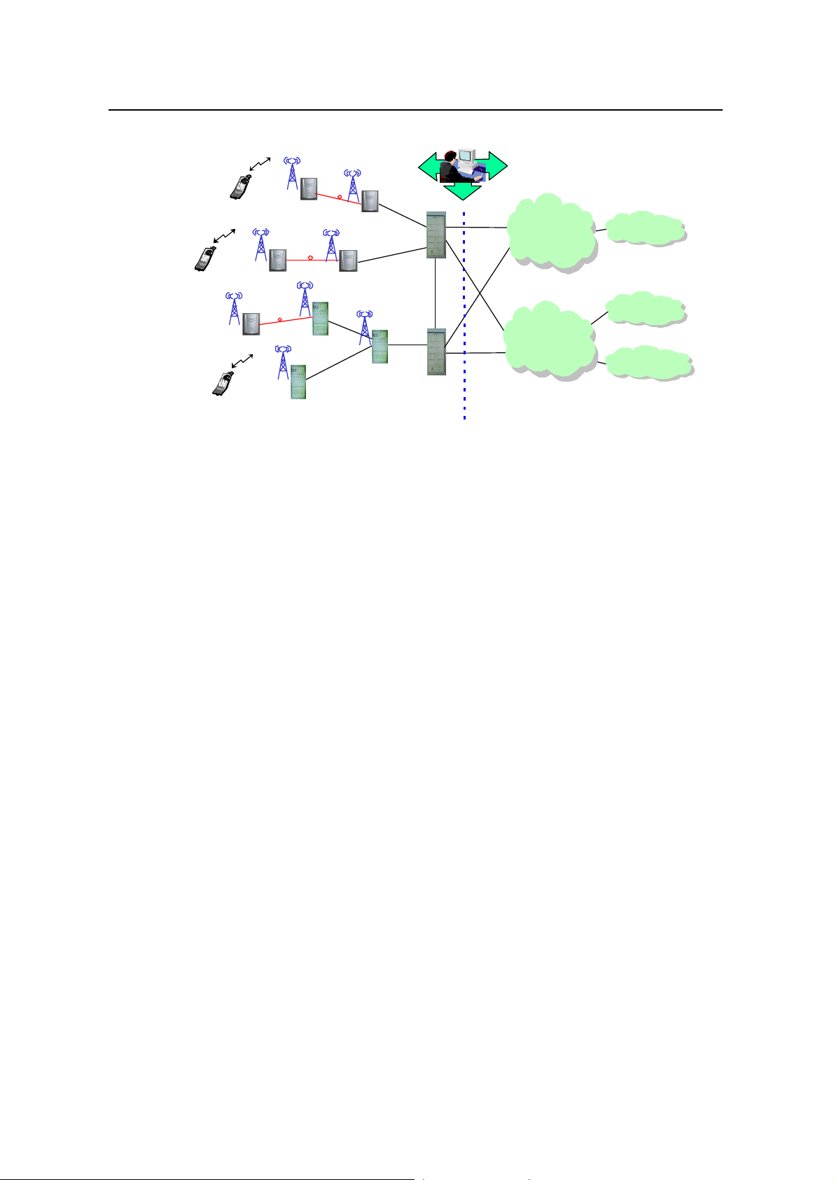
Figure 1-1 shows the network of cdma2000 1X system. This manual aims to
introduce the BTS of the BSS part, therefore this figure details the network structure
of BSS.
1-1
Page 5
User Manual
Mobile integrated
iSiteC BTS3601C CDMA Base Station
System Description
Chapter 1 System Overview
management system
MS
MS
ODU3601C
MS
ODU3601C
ODU3601C
cBTS3612
BTS3601C
cBTS3612
BTS3601C
Abis
Abis
cBTS3612
Abis
BSC/PCF
A3/A7
BSC/PCF
A10/A11
A10/A11
A1/A2
A1/A2
Packet domain
network equipment
Circuit domain
network equipment
BSS CN
MS: Mobile Station BSC: Base Station Controller
ISDN: Integrated Services Digital Network PLMN: Public Land Mobile Network
PSTN: Public Switched Telephone Network PCF: Packet Control Function
BSS: Base Station Subsystem CN: Core Network
Figure 1-1 Network structure of Huawei cdma2000 1X mobile communication system
l BTS3601C
Internet
PLMN
PSTN/ISDN
BTS3601C is an outdoor one-carrier BTS. It transmits/receives radio signals so as to
realize the communication between the radio network system and the Mobile Station
(MS).
l cBTS3612
cBTS3612 is an indoor BTS equipment. The maximum capacity of single cabinet
contains 12 sector-carriers. Same with BTS3601C, it also transmits/receives radio
signals to accomplish the communication between the radio network system and the
MS.
l ODU3601C
ODU3601C is a single-carrier outdoor BTS. It shares the resource of its upper -level
BTS, including baseband processing unit, main control unit and clock unit. It
implements radio signal transmission and reception together with the upper-level
BTS.
l Base Station Controller (BSC)
BSC performs the following functions: BTS control and management, call connection
and disconnection, mobility management, power control, and radio resource
management. It provides stable and reliable radio connections for the upper-level
services through soft/hard handoff.
l Packet Control Function (PCF)
1-2
Page 6

User Manual
iSiteC BTS3601C CDMA Base Station
PCF is used for the management of Radio-Packet (R-P) connection. As radio
resources are limited, they should be released when subscribers are not sending or
receiving information, but the Peer-Peer Protocol (PPP) connection must be
maintained. PCF shields the radio mobility against the upper-level services through
the handoff function.
l Mobile Station (MS)
MS is mobile subscriber equipment that can originate and receive calls, and can
communicate with BTS.
1.1.2 Market Orientation of BTS3601C
Huawei BTS3601C is fully compatible with IS-95A/B and IS-2000 standards.
BTS3601C is an outdoor BTS, configured with one carrier. It features small size, easy
installation, flexible networking, less investment and fast network construction.
BTS3601C can be used in residential quarters and urban hot spots / blind spots, and
provide small-capacity wide-coverage for remote areas (such as rural area, grassland,
highway, scenic spots).
System Description
Chapter 1 System Overview
1.2 System Feature
BTS3601C is a highly integrated product which can satisfy customer's different
demands for capacity, configuration, installation, power supply, transmission and
services. It is a typical "All In One" BTS with the following features:
I. Convenient operation and maintenance
l It provides remote centralized maintenance and alarm reporting, real-time status
query, on-line board test and system fault locating, as well as system restart.
l A Telnet Server is provided, through which users can log on to BTS3601C in the
standard Telnet mode via the local Ethernet interface for operation and
maintenance.
l Its modularized structure reduces the internal connections and improves the
reliability of the system, and thus makes the installation and maintenance easier.
l In the case of system interruption due to power supply or transmission causes,
the BTS3601C can restart automatically right after the faults are cleared.
II. Flexible configuration and networking
l Its Abis interface supports 1 E1 or 1 Synchronization Transfer Mode 1 (STM-1)
port, which can be configured flexibly.
l BTS3601C can be configured into an omni or directional BTS. If equipped with
power splitter, it can be configured in the S(0.5/0.5) mode.
1-3
Page 7

User Manual
iSiteC BTS3601C CDMA Base Station
l It supports various configuration modes like S(1/1) and S(1/1/1) through
cascading ODU3601Cs.
l For optical transmission, it supports chain and ring networking modes.
Configuration and networking details are available in "3.7 Configuration and
Networking"
&
Note:
To meet the actual implementation requirements, the external E1 interface of BTS3601C can be
confiured as the T1 interface. Unless otherwise specified, the following description about E1 interface is
also applicable to T1 interface.
System Description
Chapter 1 System Overview
III. Support for multi-bands
BTS3601C supports 450MHz and 800MHz bands, therefore, it can be applied in the
450MHz communication system and the 800MHz communication system.
IV. Hierarchical power supply
If the BTS3601C is equipped with a 40AH storage battery, it can keep working
normally for 1 hour after the AC power is broken off, then the power amplification
module will be switched off, and the BTS can maintain transmission for another 8
hours.
V. Easy installation
Featuring small size, light weight and mains supply, BTS3601C does not require an
equipment room or air conditioner. It neither requires a special tower as it can be
easily installed on a metal post, stayed tower or on the wall. All these can reduce the
site construction cost without affecting the network quality.
VI. Excellent protection performance
Equipped with built-in power supply unit, temperature control unit and equipment
monitoring unit, it can be applied in any severe environment.
BTS3601C is dust-proof, anti-burglary, water-proof, damp-proof. With its protection
performance in compliance with the IP55 (IEC 60529: Degrees of protection provided
by enclosure), it operates normally in different whether conditions.
1-4
Page 8

User Manual
iSiteC BTS3601C CDMA Base Station
VII. Pleasing appearance
Huawei BTS3601C has a compact structure and is aesthetically designed, which
makes it an attractive solution for both indoor and outdoor facilities.
System Description
Chapter 1 System Overview
1.3 Technical Index
The technical indices include engineering, protection, capacity and performance
indices.
The engineering indices include power supply, power consumption, weight,
dimensions and other indices involved in engineering installation.
The protection indices refer to the capabilities of the main external interfaces against
surge current.
The capacity indices include the carrier capacity and channel capacity.
The performance indices refer to the technical parameters of its transceiver and the
reliability indices of the whole system.
1.3.1 Engineering Index
Power supply
Power consumption
Weight
Operation environment
Cabinet dimensions
(height%width%depth)
~220V (150~300V AC)
<350W (In normal temperature, while the heating plate is not working)
<700W (In low temperature, while the heating plate is working)
<45kg
Temperature: -40âC~+55âC
Relative humidity 5%~100%
700mm%450mm%330mm
1.3.2 Protection Index
E1 interface
RF feeder interface
AC power supply interface
(for connecting AC lightning
protection box)
Satellite feeder interface (for
connecting lightning arrestor
for satellite feeder)
Differential mode 5kA, or common mode 10kA surge current
Differential mode 8kA, or common mode 8kA surge current
Differential mode 40kA, or common mode 40kA surge current
Differential mode 8kA, or common mode 8kA surge current
1-5
Page 9

User Manual
iSiteC BTS3601C CDMA Base Station
1.3.3 Capacity Index
System Description
Chapter 1 System Overview
Number of sector-carriers
Number of channels
1.3.4 Performance Index
I. Transmission
l 450MHz band
Working frequency
Channel bandwidth
Channel precision
Frequency tolerance [!
l 800MHz band
Frequency coverage
Channel bandwidth
Transmit power
Configuration of single-BTS: 1 sector-carrier
Configuration of cascaded ODU3601Cs: 3 sector-carriers
96 reverse channels and 192 forward channels, satisfying the 3
sector-carriers application
460~470MHz
1.23MHz
25kHz
0.05ppm
20W (the maximum value measured at the feeder port of the cabinet)
869Ã894MHz
1.23MHz
Channel step length
Frequency tolerance [!
Transmit power
II. Reception
l 450MHz band
Signal receiving sensitivity
Working frequency
Channel bandwidth
Channel precision
l 800MHz band
30kHz
0.05ppm
20W (the maximum value measured at the feeder port of the cabinet)
450Ã460MHz
1.23MHz
25kHz
-127dBm (RC3, main and diversity reception)
1-6
Page 10

User Manual
iSiteC BTS3601C CDMA Base Station
Working frequency
System Description
Chapter 1 System Overview
824Ã849MHz
Channel bandwidth
Channel step length
Signal receiving sensitivity
1.23MHz
30kHz
-128dBm (RC3, main and diversity reception)
III. System reliability
Mean Time Between Failures
(MTBF)
Mean Time To Repair (MTTR) [
Availability m
100,000 hour
m
1 hour
99.999%
&
Note:
Reliability refers to the product capability of performing specified functions under the specified conditions
and in specified time.
Mean Time Between Failures (MTBF): applicable to recoverable systems.
Mean Time To Repair (MTTR): including the time of fault checking, isolation, unit replacement and
recovery.
Availability (A): a comprehensive index to measure the system availability.
1.4 External Interface
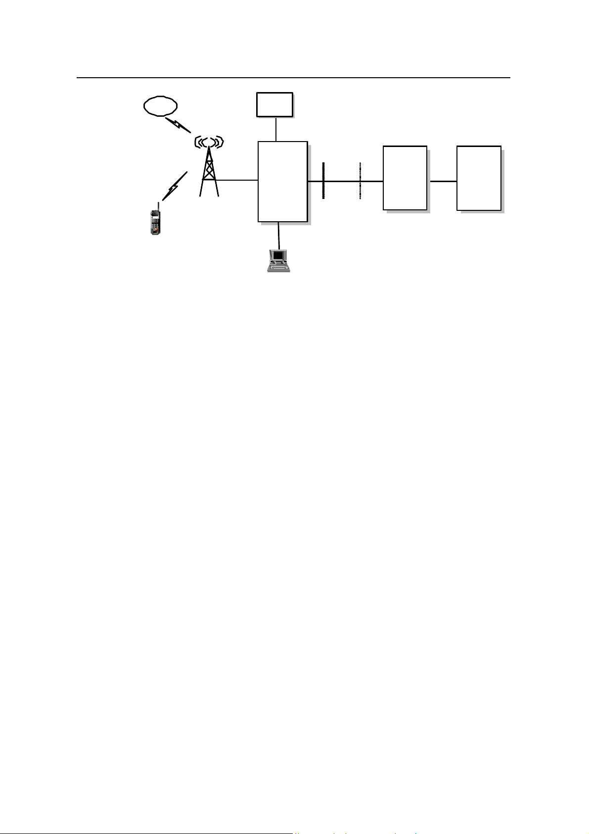
The external interfaces of BTS3601C are shown in the Figure 1-2.
1-7
Page 11
User Manual
iSiteC BTS3601C CDMA Base Station
Satellite
Satellite
Um interface
Um interface
MS
MS
Sync. Interface
Sync. Interface
Figure 1-2 External interfaces of BTS3601C
l Um interface: Interface with MS.
l Abis interface: Interface with BSC.
l Operation and Maintenance Link (OML) interface: Interface with the remote OMC.
It shares the transmission resources with Abis interface.
l Local Maintenance Function (LMF) interface: Interface with BTS local
maintenance console.
l System synchronization interface: Including GPS/GLONASS antenna interface
and system external synchronization interface. When GPS/GLONASS is not
available and there is other clock synchronization equipment, the clock
synchronization signals of the equipment can be output to the external
synchronization interface of BTS3601C system.
l BTS test interface: Interface for BTS test, providing such signals as 10MHz and
2s signal.
Test
Test
equipment
equipment
Clock test
Clock test
interface
interface
BTS3601C
BTS3601C
LMF interface
LMF interface
LMF
LMF
Abis interface
Abis interface
OML interface
OML interface
System Description
Chapter 1 System Overview
BSC
BSC
OMC
OMC
1.4.1 Um Interface
I. Overview
In Public Land Mobile Network (PLMN), MS is connected with the fixed part of the
network through the radio channel. The radio channel allows the subscribers to be
connected with the network and to enjoy telecommunication services.
To implement interconnection between MS and BSS, systematic rules and standards
should be established for signal transmission on radio channels. The standard for
regulating radio channel signal transmission is called radio interface, or Um interface.
Um interface is the most important interface among the many interfaces of CDMA
system. Firstly, standardized radio interface ensures that MSs of different
1-8
Page 12
User Manual
iSiteC BTS3601C CDMA Base Station
manufacturers are fully compatible with different networks. This is one of the
fundamental conditions for realizing the roaming function of CDMA system. Secondly,
radio interface defines the spectrum availability and capacity of CDMA system.
Um interface is defined with the following features:
l Channel structure and access capacity.
l Communication protocol between MS and BSS.
l Maintenance and operation features.
l Performance features.
l Service features.
II. Um interface protocol model
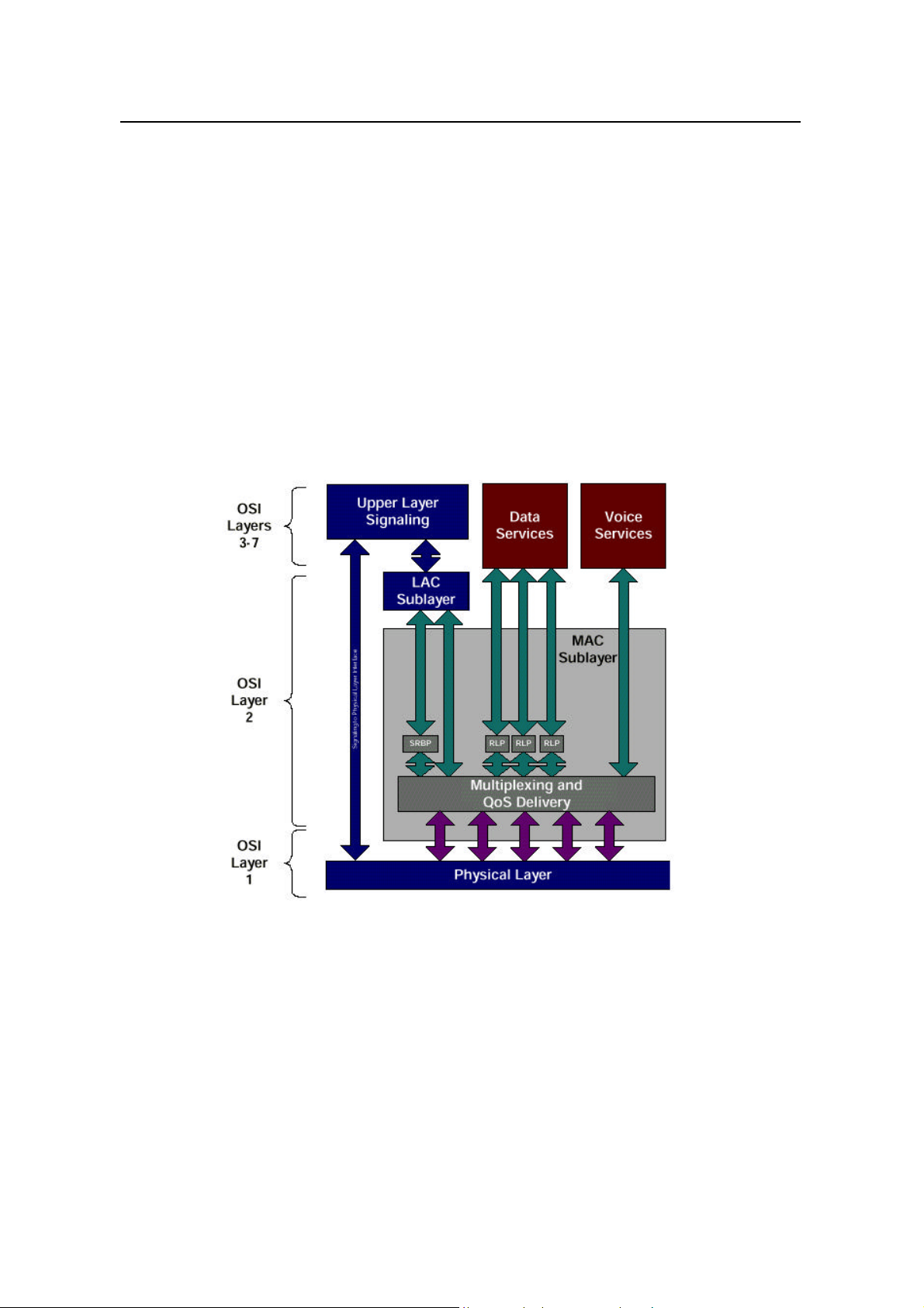
Um interface protocol stack is in 3 layers, as shown in Figure 1-3.
System Description
Chapter 1 System Overview
Figure 1-3 Um interface layered structure
Layer 1 is the physical layer, that is, the bottom layer. It includes various physical
channels, and provides a basic radio channel for the transmission of higher layer
information.
Layer 2 is the data link layer, including Medium Access Control (MAC) sublayer and
Link Access Control (LAC) sublayer. The MAC sublayer performs the mapping
between logical channels and physical channels, and provides Radio Link Protocol
(RLP) function. The LAC sublayer performs such functions as authentication,
Automatic Repeat Request (ARQ), addressing and packet organization.
1-9
Page 13

User Manual
iSiteC BTS3601C CDMA Base Station
Layer 3 is the top layer. It performs Radio Resource Management (RM), Mobility
Management (MM) and Connection Management (CM) through the air interface.
III. Physical layer
1) Working band
Band Forward band Reverse band
450MHz 460 - 470MHz 450 - 460MHz 10MHz 1.23 MHz 1.25 MHz
800MHz 869 - 894 MHz 824 - 849 MHz 45MHz 1.23 MHz 1.23 MHz
2) Physical layer function
l Service bearer: the physical channel in the physical layer provides bearer for the
logical channel of the higher layer.
l Bit error check: the physical layer provides transmission service with error
protection function, including error checking and error correction.
l User identification: the physical layer provides an exclusive ID for every user by
code division.
3) Radio configuration
Duplex
spacing
System Description
Chapter 1 System Overview
Channel width Carrier spacing
The physical layer supports multiple Radio Configurations (RCs). Different RCs
support different traffic channel data rates. For detailed introduction, please refer to
Section 3.4.3 Radio Configuration and Channel Support.
IV. Data link layer
Data link layer at Um interface includes two sublayers, MAC and LAC. The purpose of
introducing MAC and LAC is to:
l Support higher level services (signaling, voice, packet data and circuit data).
l Support data services of multiple rates.
l Support packet data service and circuit data service of higher quality (QoS).
l Support multi-media service, that is, processing voices, packet data and circuit
data of different QoS levels at the same time.
1) MAC sublayer
To support data service and multi-media service, cdma2000 1X provides powerful
MAC layer to ensure the reliability of services. MAC layer provides two important
functions:
l Radio Link Protocol (RLP), ensuring reliable transmission on the radio link.
l Multiplex function and QoS function, with diversified services and higher service
quality.
2) LAC sublayer
LAC layer performs such functions as Automatic Repeat Request (ARQ),
authentication and addressing.
1-10
Page 14

User Manual
iSiteC BTS3601C CDMA Base Station
V. Layer 3
The higher layer signaling performs the functions such as radio resource
management, mobility management and call connection management on air
interface.
1) Radio resource management
The radio resource management functions include:
l Radio channel management
It is used to establish, operate and release radio channels, and help to realize soft
handoff, softer handoff and hard handoff.
l Power control
Various power control technologies are used on Um interface to reduce the system
interference and improve the system capacity.
2) Mobility management
It is used to support the mobility features of the mobile subscriber, performing such
functions as registration, authentication and Temporary Mobile Subscriber Identity
(TMSI) re-allocation.
System Description
Chapter 1 System Overview
3) Connection management
It is used to setup, maintain and terminate calls.
1.4.2 Abis Interface
I. Overview
Abis interface is defined as the interface between BSC and BTS, the two functional
entities in the Base Station Subsystem (BSS). It is the interface defined for BTS
accessing BSC via the terrestrial link.
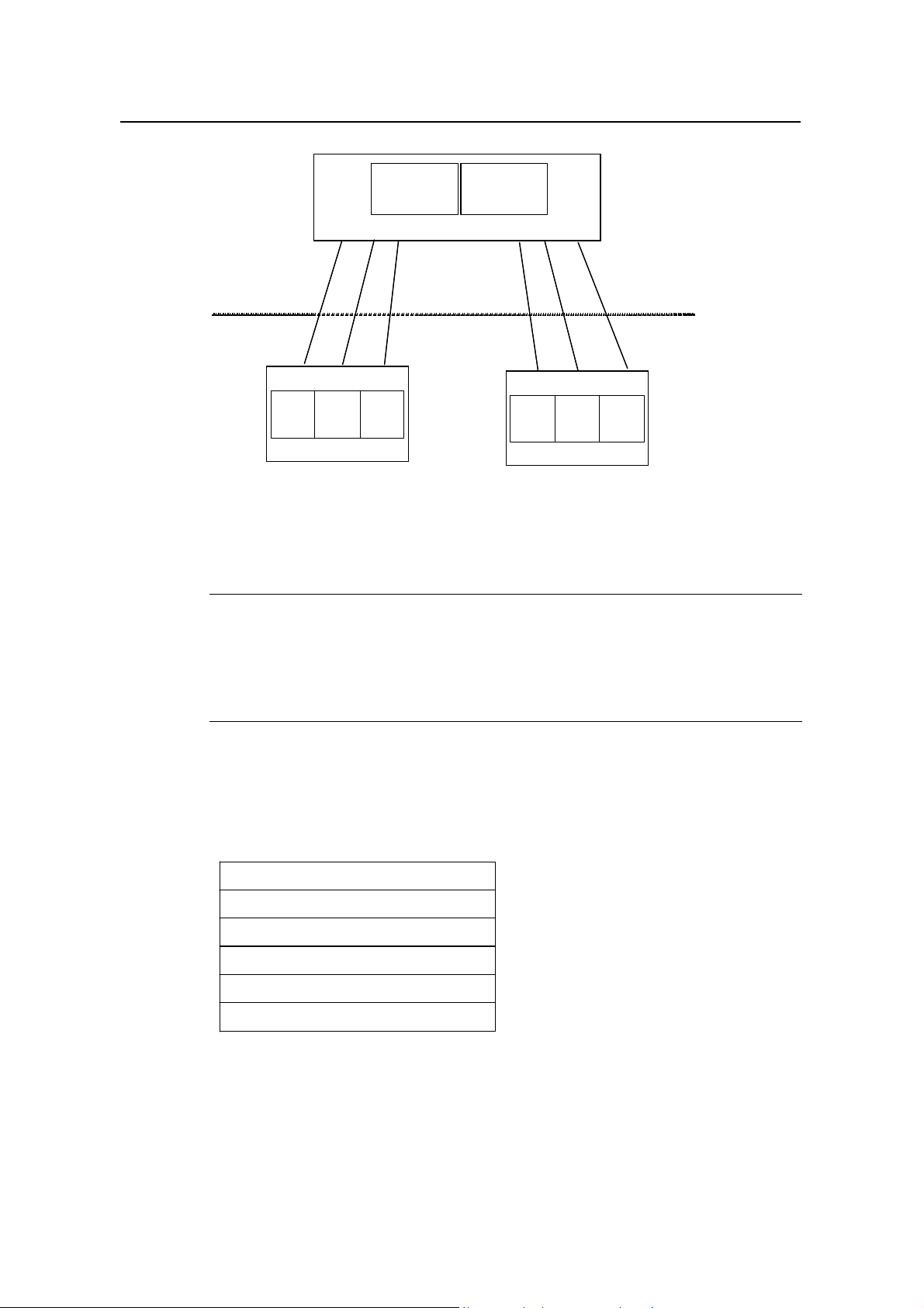
1) Structure of Abis interface
Abis interface consists of three parts: Abis traffic, Abis signaling and OML signaling,
as shown in Figure 1-4.
Abis traffic is the interface connecting SDU of BSC and the CEs of BTS. It is used to
bear user traffic.
Abis signaling is the interface connecting SPU of BSC and the MC of BTS, It is used
to control the cell setup, transmission of messages over paging channels and access
channels, and call setup & release.
OML signaling is used to perform operation and maintenance. It is defined by
equipment manufacturers. On Abis interface, there is a transparent channel used to
bear OML between OMC and OMU of BTS.
1-11
Page 15
User Manual
iSiteC BTS3601C CDMA Base Station
Abis Interface
Abis Interface
SPU: Signaling Processing Unit CEs: Channel Elements
SDU: Selection/Distribution Unit OMU: Operation and Maintenance Unit
MC: Main Control unit
MC
MC
Signaling
Signaling
Abis
Abis
CEs
CEs
BTS
BTS
Abis
Abis
Traffic
Traffic
OML
OML
OMU
OMU
SPU
SPU
BSC
BSC
SDU
SDU
OMU
OMU
OML
OML
Abis
Abis
Traffic
Traffic
CEs
CEs
BTS
BTS
System Description
Chapter 1 System Overview
Abis
Abis
Signaling
Signaling
MC
MC
Figure 1-4 Composition of Abis interface
&
Note:
The CFMR (CDMA radio frame process (FP MAC RLC) board) board of BSC carrys out the SDU
function, and the CSPU (CDMA Signal Process Unit) board of BSC carrys out the SPU function, the
MBPB board of BTS3601C carrys out the MC, CEs and OMU fouctions.
2) Protocol stack of Abis interface
The protocol stack used by Abis signaling and the signaling for operation &
maintenance is as follows:
Abis Signaling Application/OAM ApplicationAbis Signaling Application/OAM Application
TCP
IP
AAL5
ATM
Physical Layer
Protocol stack used by Abis traffic is as follows:
1-12
Page 16

User Manual
iSiteC BTS3601C CDMA Base Station
Abis Traffic
SSSAR
AAL2
ATM
Physical Layer
II. Physical layer
The physical layer of Abis interface can use E1 interface or STM-1 interface.
Each BTS3601C has an E1 link connected with BSC. It realizes transmission through
the ATM User Network Interface (UNI) protocol. Namely, it maps ATM cells to the
T1/E1 frame to implement transmission.
III. Data link layer
System Description
Chapter 1 System Overview
ATM is used on the data link layer of Abis interface.
Adaptation of Abis signaling is performed based on AAL5, and is borne in IP Over
ATM (IPoA) mode. At Abis interface, Abis signaling path connects the Main Control
(MC) software and Signaling Processing Unit (SPU) of BSC via Permanent Virtual
Connection (PVC) to transmit Abis signaling. The signaling transmission path for
implementing related O&M operations is also borne by a PVC connecting the
Operation and Maintenance Unit (OMU) of BTS and BSC. The BSC forwards the
signaling to OMC transparently, and does not process any O&M signaling.
Adaptation of Abis traffic is performed based on AAL2. At Abis interface, several
PVCs are used to connect the channel processing unit of BTS and SDU of BSC, for
BTS to transmit the uplink data received from the air interface to BSC, and for BSC to
transmit the downlink data to be transmitted via the air interface to BTS.
IV. Layer 3 - traffic management
At Abis interface, Abis signaling, OML signaling and Abis traffic are in the domain of
traffic management. Specifically, Abis traffic management includes the following
functions:
1) BTS logic O&M function
l Resource status indication: With this function, BTS requests logic configuration
from BSC, reports logic status to BSC and checks logic resource regularly.
l Cell configuration: With this function, BSC configures logic parameters of cells
for BTS, including cell pilot Pseudo Noise (PN) offset, sector gain, common
channel number and parameter.
1-13
Page 17

User Manual
iSiteC BTS3601C CDMA Base Station
l Overhead message updating: With this function, BSC configures or update
overhead message to BTS.
l Cell breath control function.
l Cell blocking function.
l Radio measurement report function.
2) Common channel management function
Paging channel management procedure: It is used to transmit paging channel
messages from BSC to MSs through Abis interface.
Access channel management procedure: It is used to transmit access channel
messages received on the access channel of BTS to BSC through Abis interface.
3) Dedicated channel setup and release function
This procedure is used to control the setup and release of dedicated radio channel
and Abis interface terrestrial channel.
Abis interface supports the setup and release of various dedicated channels specified
in IS95A/B and cdma2000 1X, including IS95-FCH, IS95-SCCH, IS2000-FCH,
IS2000-DCCH and IS2000-SCH.
System Description
Chapter 1 System Overview
Each radio channel is allocated with one AAL2 link on Abis interface to bear user
traffic data.
Caution:
For softer handoff, only one AAL2 link is allocated on Abis interface.
4) Traffic channel bearing function
BTS needs to process Abis interface frame protocol. It transmits the data received
from the reverse traffic channel on the air interface to BSC, and transmits the data
from BSC through the forward traffic channel on the air interface.
Traffic channel bearing procedure also performs the functions such as AAL2 traffic
matching, time adjustment of traffic data frame, reverse outer loop power control
adjustment and forward power control adjustment.
5) Power control function
Abis interface suppor ts various power controls. Power control is performed through
parameter configuration. Power control falls into four types: quick forward closed-loop
power control, slow forward closed-loop power control, quick reverse closed-loop
power control and reverse open-loop power control.
1-14
Page 18
User Manual
iSiteC BTS3601C CDMA Base Station
1.4.3 Other Interface
I. ODU3601C interface
This interface is located between the Micro-bts Transceiver Module (MTRM) of
BTS3601C and the MTRM of ODU3601C. It transmits baseband data through optical
fibers (including service information and operation & maintenance information) so that
BTS3601C can control the ODU3601C.
II. OML interface
OML interface is between BTS and remote OMC. It is actually one of the Abis
interface applications. But on the application layer, OML interface is between BTS
and the remote OMC. OML interface shares resources with Abis interface, including
physical layer, ATM, AAL5 and TCP/IP. For details, please refer to the introduction to
Abis interface.
OML interface is used for OMC to perform operation and maintenance to BTS. It is
defined by equipment manufacturers. On Abis interface, it is a transparent path.
System Description
Chapter 1 System Overview
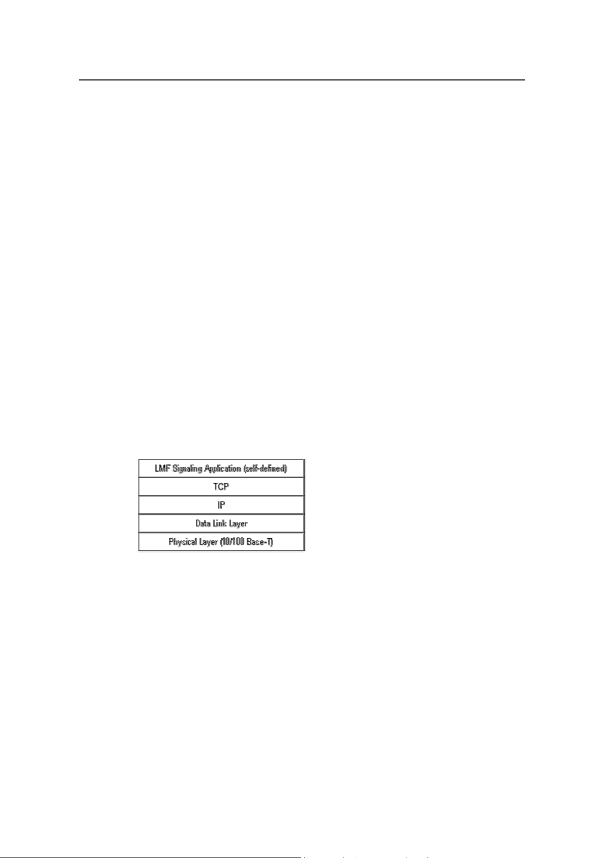
III. LMF interface
LMF interface is the interface between BTS and Local Maintenance Function (LMF)
entity. Its interface protocol stack is shown as below:
IV. System synchronization interface
System synchronization interface includes GPS/GLONASS antenna interface and
system external synchronization interface.
l GPS/GLONASS antenna interface
GPS is in compliance with ICD200c: IRN-200C-001-IRN-200C-004: Interface Control
Document of GPS. GLONASS is in compliance with GPS/GLONASS Receiver
Interface Language (GRIL).
l System external synchronization interface
The external synchronization interface is used when GPS/GLONASS is not applied. It
is in compliance with the requirement of CDMA Digital Cellular Mobile Communication
1-15
Page 19

User Manual
iSiteC BTS3601C CDMA Base Station
Network GPS/GLONASS Dual-Mode Receiver and Base Station Interface
Specifications.
V. Test interface
The test interface provides 10MHz and 2s signals that may be needed for test
instruments.
VI. Power supply interface
BTS3601C supports 220V AC power supply. It provides external 220V AC interface
and 24V DC battery interface.
1.5 Reliability Design
Reliability design of a system is shown in the stability and reliability of the product
during operation.
System Description
Chapter 1 System Overview
Huawei BTS3601C is designed based on the following standards:
l TIA/EIA/IS-95A CDMA Radio Interface Specifications
l TIA/EIA/IS-95B CDMA Radio Interface Specifications
l TIA/EIA/IS-2000 CDMA Radio Interface Specifications
l TIA/EIA/IS-97D CDMA Base Station Minimum Performance Standard
l Huawei product reliability design index and related technical specifications
With various measures taken, the design of boards is in strict accordance with the
requirement of above standards pertaining to reliability.
1.5.1 Hardware Reliability Design
I. De-rating design
To improve system reliability and prolong the service life of components, components
are carefully selected and strictly tested, and less stress (electrical stress and
temperature stress) is to be borne in actual operation than its designed rating.
II. Selection and control of component
The category, specifications and manufacturers of the components are carefully
selected and reviewed according to the requirements of the product reliability and
maintainability. The replaceability and normalization of components is one of the main
factors for the decision, which help to reduce the types of components used and
hence improve the availability of the system.
1-16
Page 20

User Manual
iSiteC BTS3601C CDMA Base Station
III. Board level reliability design
Many measures have been taken in board design to improve its reliability.
Redundancy configuration is applied for key components to improve system reliability.
l Key circuits are designed by Huawei, which lays the foundation of high reliability.
l The hardware WATCHDOG is equipped for the board, and the board can
automatically reset in case of fault.
l The board is provided with the functions of over-current and over-voltage
protection and the function of temperature detection.
l Strict thermal analysis and simulation tests are conducted during the design of
boards for the purpose of ensuring longtime operation.
l The board software and important data is stored in the non-volatile memory, so
that the board can be restarted when software upgrading fails.
IV. Fault detection, location and recovery
The BTS system is equipped with the functions of self-detection and fault diagnosis
that can record and output various fault information. Common software and hardware
faults can be corrected automatically.
System Description
Chapter 1 System Overview
The hardware fault detection functions include fault locating, isolating and automatic
switchover. The maintenance engineers can identify the faulty boards easily with the
help of the maintenance console.
The BTS3601C system also supports the reloading of configuration data files and
board execution programs.
V. Fault tolerance and exceptional protection
When faults occur, the system usually will not be blocked.
The system will make a final confirmation on a hardware fault through repeated
detection, thus avoiding system reconfiguration or QoS deterioration due to
contingent faults.
VI. Thermal design
The influence of temperature on the BTS3601C has been considered in the design.
Thermal design primarily concerns the selection of components, circuit design
(including error tolerance, drift design and derating design), structure design and heat
dissipation, so that the BTS3601C can work reliably in a wide range of temperatures.
The first consideration in thermal design is to balance the heat distribution of the
system. Corresponding measures are taken in the place where heat is more likely to
be accumulated.
1-17
Page 21

User Manual
iSiteC BTS3601C CDMA Base Station
VII. Maintainability
The purpose of maintainability design is to define the workload and nature of the
maintenance, so as to cut the maintenance time. The main approaches adopted
include standardization, modularization, error prevention, and testability improvement,
which can simplify the maintenance work.
VIII. EMC design
The design ensures that BTS3601C will not degrade to an unacceptable level due to
the electromagnetic interference from other equipment in the same electromagnetic
environment. Neither the BTS3601C will cause other equipment in the same
electromagnetic environment to degrade to an unacceptable level.
IX. Lightning protection
To eliminate the probability of lightning damage on the BTS3601C system, proper
measures are taken with respect to the lightning protection for DC power supply, BTS
trunk lines and antenna & feeder system. For details, please refer to "3.6 Lightning
Protection".
System Description
Chapter 1 System Overview
1.5.2 Software Reliability Design
Software reliability mainly includes protection performance and fault tolerance
capability.
I. Protection performance
The key to improve software reliability is to reduce software defects. Software
reliability of BTS3601C is ensured through the quality control in the whole process
from system requirement analysis, system design to system test.
Starting from the requirement analysis, software development process follows the
regulations such as Capability Mature Mode (CMM), which aim to control faults in the
initial stage.
In software design, much attention is devoted to the designing method and
implementation: the software is designed in a modular structure, and in a loose
coupling mechanism. When a fault occurs to one module, other modules will not be
affected. In addition, preventive measures such as fault detection, isolating and
clearing are also applied to improve the system reliability. Other effective methods
include code read-through, inspection, and unit test.
Various software tests are conducted to improve the software reliability. Test
engineers participate the whole software development process, from unit test to
1-18
Page 22

User Manual
iSiteC BTS3601C CDMA Base Station
system test. They make plans strictly following the demand of the upper -level flow,
which ensure the improvement of software reliability. Additionally, test plans are
modified and improved with the tests.
II. Fault tolerance capability
Fault tolerance capability of the software system means that the whole system would
not collapse when a minor software fault occurs. That is, the system has the
self-healing capability. The fault tolerance of BTS3601 software is represented in the
following aspects:
l All boards work on a real-time operating system of high reliability.
l If software loading fails, the system can return to the version that was
successfully loaded last time.
l Important operations are recorded in log files.
l Different authority levels are provided for operations, so as to prevent users from
performing unauthorized operations.
l Warnings are given for the operations that will cause system reboot (such as
reset operation). The operator is required to confirm such operations.
System Description
Chapter 1 System Overview
1-19
Page 23
User Manual
iSiteC BTS3601C CDMA Base Station
Chapter 3 System Function
3.1 Call Procedure Introduction
Call procedure includes speech service call procedure and data service call
procedure. This section gives some typical examples to introduce the MS call
procedures.
3.1.1 Speech Service Call Procedure
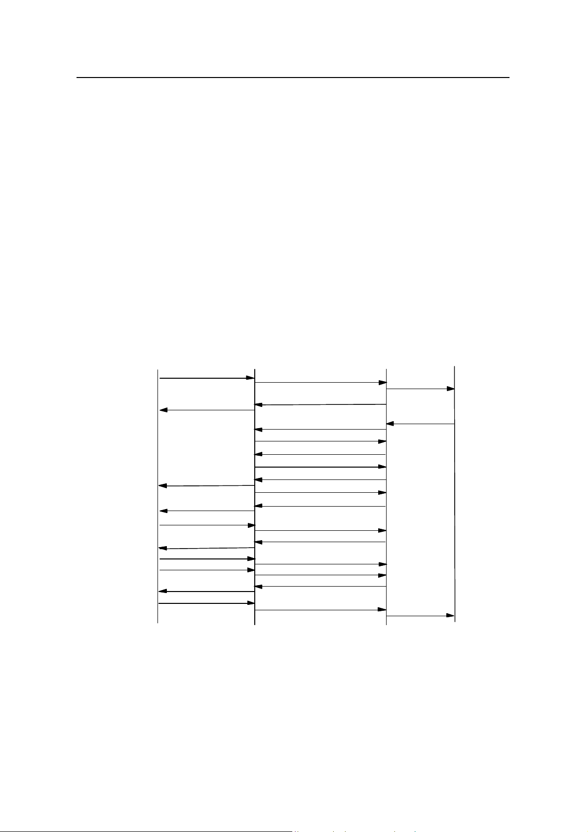
I. Mobile-Originated Call (MOC)
MOC procedure is illustrated in Figure 3-1.
System Description
Chapter 3 System Function
MS BTS
MS BTS
Origination Msg
ACH
ACH
PCH
PCH
TCH
TCH
PCH
PCH
TCH
TCH
TCH
TCH
TCH
TCH
TCH
TCH
TCH
TCH
TCH
TCH
Origination Msg
Base Ack Order
Base Ack Order
Null Traffic Data
Null Traffic Data
ECAM
ECAM
Traffic Channel Preamble
Traffic Channel Preamble
Base Ack Order
Base Ack Order
Idle TCH Data
Idle TCH Data
MS AckOrder
MS AckOrder
Service Connect Msg
Service Connect Msg
Service Connect Complete
Service Connect Complete
Figure 3-1 MOC procedure
Abis-ACH Msg Transfer(ORM)
Abis-ACH Msg Transfer(ORM)
Abis-PCH MsgTransfer(Base Ack)
Abis-PCH MsgTransfer(Base Ack)
Abis-BTS Setup
Abis-BTS Setup
Abis-Connect
Abis-Connect
Abis-Connect Ack
Abis-Connect Ack
Abis-BTS Setup Ack
Abis-BTS Setup Ack
Abis-IS2000 FCH Fwd(Null data)
Abis-IS2000 FCH Fwd(Null data)
Abis-IS2000 FCH Rvs(Idledata)
Abis-IS2000 FCH Rvs(Idledata)
Abis-PCH MsgTransfer(ECAM)
Abis-PCH MsgTransfer(ECAM)
Abis-IS2000 FCH Rvs(Preamble)
Abis-IS2000 FCH Rvs(Preamble)
Abis-IS2000 FCH Fwd(BaseAck)
Abis-IS2000 FCH Fwd(BaseAck)
Abis-IS2000 FCH Rvs(IdleData)
Abis-IS2000 FCH Rvs(IdleData)
Abis-IS2000 FCH Rvs(Ms Ack)
Abis-IS2000 FCH Rvs(Ms Ack)
Abis-IS2000 FCH Fwd(ServiceConnect)
Abis-IS2000 FCH Fwd(ServiceConnect)
Abis-IS2000 FCH Rvs(SerConn Comp)
Abis-IS2000 FCH Rvs(SerConn Comp)
BSC
BSC
CM Service Req
CM Service Req
Assignment Req
Assignment Req
Assignment Complete
Assignment Complete
MSC
MSC
(1)
(1)
(2)
(2)
(3)
(3)
(4)
(4)
(5)
(5)
(6)
(6)
(7)
(7)
(8)
(8)
(9)
(9)
(10)
(10)
(11)
(11)
(12)
(12)
(13)
(13)
(14)
(14)
(15)
(15)
(16)
(16)
(17)
(17)
1) MS sends "Origination Message" on access channel. After receiving the
message, BTS sends “Abis-ACH Msg Transfer” message to BSC.
2) BSC sends “CM Service Request” message to MSC to request service
assignment. Meanwhile, BSC sends “BS Ack Order” to BTS via “Abis-PCH Msg
Transfer” message. BTS sends “BS Ack Order" on paging channel to the MS.
3-1
Page 24

User Manual
iSiteC BTS3601C CDMA Base Station
3) MSC sends "Assignment Request" message to BSC to request BSS to assign
radio resources.
4) BSC sends “Abis-BTS Setup” message to BTS to request BTS to allocate radio
resources for the call.
5) BTS sends “Abis-Connect” message to BSC for establishing Abis service
connection.
6) BSC sends “Abis-Connect Ack” to BTS in response to the “Abis-Connect”
message.
7) After resources allocation, BTS sends “Abis-BTS Setup Ack” message to BSC.
8) BSC sends “Abis-IS2000 FCH Fwd” message to BTS, and orders BTS to send
null frame to MS on forward traffic channel.
9) After receiving “Abis-IS2000 FCH Fwd” message, BTS sends idle frame to BSC
via “Abis-IS2000 FCH Rvs” message, and performs Abis link delay adjustment.
10) BSC sends channel assignment message to BTS via “Abis-PCH Msg Transfer”
message. BTS forwards the channel assignment message to MS on paging
channel.
11) MS begins to send traffic channel preamble on the assigned reverse traffic
channel. After BTS captures the preamble, it sends traffic channel preamble to
BSC via “Abis-IS2000 FCH Rvs” message.
12) After BSC receives traffic channel preamble from MS, BSC sends "BS Ack
Order” to BTS via “Abis-IS2000 FCH Fwd” message. BTS sends “BS Ack Order”
to MS on the forward traffic channel.
13) After MS receives “BS Ack Order”, it stops sending traffic channel preamble and
starts to send data frame on reverse traffic channel.
14) Then MS sends “MS Ack Order” on reverse traffic channel to BTS. BTS forwards
the message to BSC via “Abis-IS2000 FCH Rvs” message.
15) On receiving “MS Ack Order”, BSC sends "Service Connect" message to BTS
via “Abis-IS2000 FCH Fwd” message, then BTS forwards the message to MS.
MS starts to handle the traffic according to the designated service configuration.
16) To respond to service connection message, MS sends "Service Connect
Complete" message.
17) On receiving the "Service Connect Complete" message, BSC sends
"Assignment Complete" message to MSC.
System Description
Chapter 3 System Function
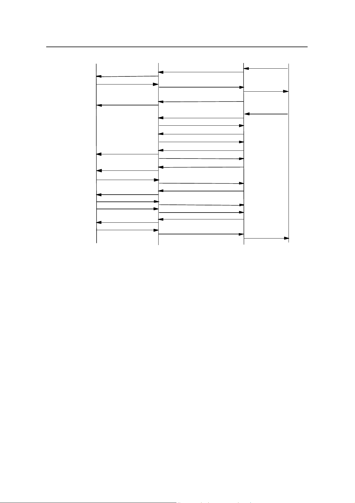
II. Mobile-Terminated Call (MTC)
MOC procedure is shown in Figure 3-2.
3-2
Page 25
User Manual
iSiteC BTS3601C CDMA Base Station
MS
MS
PCH
PCH
ACH
ACH
PCH
PCH
TCH
TCH
PCH
PCH
TCH
TCH
TCH
TCH
TCH
TCH
TCH
TCH
TCH
TCH
TCH
TCH
GPM
GPM
Paging Response
Paging Response
Base Ack Order
Base Ack Order
Null Traffic Data
Null Traffic Data
ECAM
ECAM
Traffic Channel Preamble
Traffic Channel Preamble
Base Ack Order
Base Ack Order
Idle TCH Data
Idle TCH Data
MS Ack Order
MS Ack Order
Service Connect Msg
Service Connect Msg
Service Connect Complete
Service Connect Complete
Chapter 3 System Function
BTS BSC
BTS BSC
Abis-PCH MsgTransfer(GPM )
Abis-PCH MsgTransfer(GPM )
Abis-ACH MsgTransfer(PRM)
Abis-ACH MsgTransfer(PRM)
Abis-PCH MsgTransfer(BaseAck)
Abis-PCH MsgTransfer(BaseAck)
Abis-BTS Setup
Abis-BTS Setup
Abis-Connect
Abis-Connect
Abis-Connect Ack
Abis-Connect Ack
Abis-BTS Setup Ack
Abis-BTS Setup Ack
Abis-IS2000 FCH Fwd(Null data)
Abis-IS2000 FCH Fwd(Null data)
Abis-IS2000 FCH Rvs(Idle data)
Abis-IS2000 FCH Rvs(Idle data)
Abis-PCH MsgTransfer(ECAM)
Abis-PCH MsgTransfer(ECAM)
Abis-IS2000 FCH Rvs(Preamble)
Abis-IS2000 FCH Rvs(Preamble)
Abis-IS2000 FCH Fwd(BaseAck)
Abis-IS2000 FCH Fwd(BaseAck)
Abis-IS2000 FCH Rvs(Idle Data)
Abis-IS2000 FCH Rvs(Idle Data)
Abis-IS2000 FCH Rvs(Ms Ack)
Abis-IS2000 FCH Rvs(Ms Ack)
Abis-IS2000 FCH Fwd(ServiceConnect)
Abis-IS2000 FCH Fwd(ServiceConnect)
Abis-IS2000 FCH Rvs(Ser Conn Comp)
Abis-IS2000 FCH Rvs(Ser Conn Comp)
System Description
Paging Request
Paging Request
CM Service Req
CM Service Req
Assignment Req
Assignment Req
Assignment Complete
Assignment Complete
MSC
MSC
(1)
(1)
(2)
(2)
(3)
(3)
(4)
(4)
(5)
(5)
(6)
(6)
(7)
(7)
(8)
(8)
(9)
(9)
(10)
(10)
(11)
(11)
(12)
(12)
(13)
(13)
(14)
(14)
(15)
(15)
(16)
(16)
(17)
(17)
(18)
(18)
(19)
(19)
(20)
(20)
Figure 3-2 MOC procedure
1) MSC sends "Paging Request" to BSC.
2) BSC constructs General Paging Message (GPM), embeds it into ”Abis-PCH Msg
Transfer” message, then sends it to BTS. BTS forwards the GPM on the paging
channel.
3) After MS receives paging message, it sends Paging Response Message (PRM)
to BTS. BTS forwards it to BSC in “Abis-ACH Msg Transfer” message.
4) BSC sends “CM Service Request” message to MSC to request service
assignment.
5) BSC sends “BS Ack Order” to BTS via “Abis-PCH Msg Transfer” message. BTS
sends the “BS Ack Order” on the paging channel.
6) MSC sends assignment request message to BSC to request BSS to allocate
radio resources.
7) BSC sends “Abis-BTS Setup” message to BTS to request BTS to allocate radio
resource for the call.
8) BTS sends “Abis-Connect” message to BSC for establishing Abis service
connection.
9) BSC sends “Abis-Connect Ack” to BTS in response to “Abis-Connect” message.
10) BTS completes resource allocation, and sends “Abis-BTS Setup Ack” message
to BSC.
3-3
Page 26

User Manual
iSiteC BTS3601C CDMA Base Station
11) BSC sends “Abis-IS2000 FCH Fwd” message to BTS to request BTS to send
null frame to MS.
12) After receiving “Abis-IS2000 FCH Fwd” message, BTS sends null frame to BSC
via “Abis-IS2000 FCH Rvs” message, and performs Abis link delay adjustment.
13) BSC sends channel assignment message to BTS via “Abis-PCH Msg Transfer”
message. BTS forwards the message to MS on paging channel.
14) MS begins to send traffic channel preamble on the assigned reverse traffic
channel. After capturing the preamble, BTS sends traffic channel preamble to
BSC via “Abis-IS2000 FCH Rvs” message.
15) After BSC receives the traffic channel preamble sent from MS, it sends “BS Ack
Order” to BTS via “Abis-IS2000 FCH Fwd” message. BTS forwards the order to
MS over the forward traffic channel.
16) After MS receives “BS Ack Order”, it stops sending traffic channel preamble and
starts sending data frame.
17) After MS receives “BS Ack Order", it sends “MS Ack Order" to BTS. BTS
forwards the order to BSC via “Abis-IS2000 FCH Rvs” message.
18) After BSC receives “MS Ack Order", it sends service connection message to
BTS via “Abis-IS2000 FCH Fwd” message. BTS forwards the message to MS,
and then MS starts to handle the service according to the designated service
configuration.
19) To respond to service connection message, MS sends "Service Connect
Complete" message.
20) After BSC receives the "Service Connection Complete" message, it sends
"Assignment Complete" message to MSC.
System Description
Chapter 3 System Function
3.1.2 Data Service Call Procedure
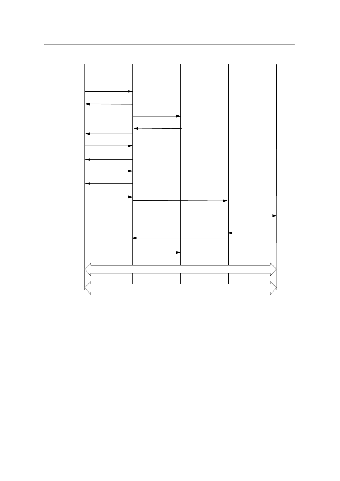
I. Mobile originated data service
The mobile originated data service procedure is shown in Figure 3-3. In the figure, the
BSS represents BTS and BSC.
3-4
Page 27
User Manual
iSiteC BTS3601C CDMA Base Station
(1)
(1)
(2)
(2)
(5)
(5)
(6) TchPreamble
(6) TchPreamble
(7)
(7)
(8)
(8)
(9)
(9)
Origination
Origination
BS ACK
BS ACK
ECAM
ECAM
Ack Order
Ack Order
BS
BS
Ack Order
Ack Order
MS
MS
Service Connect
Service Connect
BSSMS
BSSMS
MSC
MSC
(3)
(3)
CM Service Request
CM Service Request
(4) Assignment Request
(4) Assignment Request
Msg
Msg
System Description
Chapter 3 System Function
PCF PDSN
PCF PDSN
(10)
(10)
Service Connect
Service Connect
Cmp Msg
Cmp Msg
(14) A9-Connect -A8
(14) A9-Connect -A8
(15) Assignment Complete
(15) Assignment Complete
Establishing PPP connection , Mobile IP Registration
Establishing PPP connection , Mobile IP Registration
Transmitting packet data
Transmitting packet data
(11)
(11)
A9-Setup -A8
A9-Setup -A8
A11 Registration
A11 Registration
(12)
(12)
Request(Life time)
Request(Life time)
A11-Registration
A11-Registration
(13)
(13)
Reply (Life time, Accept)
Reply (Life time, Accept)
Figure 3-3 Mobile originated data service procedure
1) MS sends "Origination" message to BTS via the access channel on air interface.
2) After BTS receives the "Origination message", it sends "BS Ack Order" to MS.
3) BSC constructs a "CM Service Request" message and sends it to MSC.
4) MSC sends "Assignment Request" message to BSC to request BTS to assign
radio resources.
5) BTS sends channel assignment message over the paging channel of air
interface.
6) MS begins to send preamble in the assigned reverse traffic channel.
7) After acquiring the reverse traffic channel, BTS sends "BS ACK Order" to MS in
the forward traffic channel.
8) After receiving "BS ACK Order", MS sends "MS ACK Order", and transmits the
null service frame in the reverse traffic channel.
3-5
Page 28

User Manual
iSiteC BTS3601C CDMA Base Station
9) BTS sends service connection message/service selection response message to
MS, and designates the service configuration used for the call. MS starts to
handle the service according to the designated service configuration.
10) After receiving service connection message, MS responds with one Service
Connect Complete" message.
11) BSC sends “A9-Setup-A8” message to PCF for establishing A8 connection.
12) PCF sends “A11-Registration-Request” to PDSN for establishing A10
connection.
13) PDSN accepts A10 connection establishment request, and returns
“A11-Registration-Reply” message to PCF.
14) PCF returns “A9-Connect-A8” message to BSC. Connection between A8 and
A10 is established.
15) After both radio traffic channel and terrestrial circuit are established, BSC sends
"Assignment Complete" message to MSC.
16) MS negotiates with PDSN to establish PPP connection. In the case of Mobile IP
access, Mobile IP connection will be established. PPP message and Mobile IP
message are transmitted in traffic channel, and are transparent to BSC/PCF.
17) After PPP connection is established, the data service enters "connected" status.
System Description
Chapter 3 System Function
II. SCH establishment
This section describes establishment procedure of MS-originated Supplemental
Channel (SCH). The BSC-originated SCH establishment procedure is similar, and
only differs in the trigger condition.
There is no special SCH release procedure in the case of dynamic SCH allocation.
Instead, BSC determines SCH rate and duration. Once the time is due, SCH will be
released.
MS-originated SCH establishment procedure is shown in Figure 3-4.
3-6
Page 29

User Manual
iSiteC BTS3601C CDMA Base Station
MS BTS BSC
(1) Supplemental Channel Request Message
(9) Extended Supplemental Channel Assignment Message
(2) Abis-BTS Setup
(3) Abis Connect
(4) Abis Connect Ack
(5) Abis-BTS Setup Ack
(6)Abis Burst Request
(7)
Abis Burst Response
(8) Abis Burst Commit
System Description
Chapter 3 System Function
Figure 3-4 Reverse SCH establishment procedure
1) If the packet data call is established, MS may send “Supplemental Channel
Request Message” to BSC for establishing SCH channel.
2) BSC sends “Abis-BTS Setup” to BTS for allocating radio resource for the call.
3) After BTS establishes the channel, it sends “Abis Connect” to BSC.
4) BSC responds with “Abis Connect Ack” to BTS.
5) After BTS establishes all of the channels, it sends “Abis-BTS Setup Ack” to BSC,
indicating the completion of terrestrial circuit establishment.
6) BSC sends “Abis-Burst Request” to BTS for activating BTS.
7) BTS responds “Abis-Burst Response” message to BSC.
8) BSC sends “Abis-Burst Commit” to BTS, and BTS starts to transmit SCH.
9) BSC sends “Extended Supplemental Channel Assignment Message” and
assigns SCH channel for MS, so that the packet data service can be transmitted
at high speed in SCH channel.
3.2 Signaling Processing
BTS signaling processing serves to:
l Implement interconnection of MS and BSS/CN on the air interface layer.
l Perform part of radio resource management function under the control of BSC.
Specifically, BTS signaling processing performs the following functions: signaling
processing on Abis physical layer and transmission layer, channel resource
management, Abis traffic link management, BTS logic O&M processing, common
channel processing, dedicated channel establishment and release, traffic bearing and
power control.
3-7
Page 30

User Manual
iSiteC BTS3601C CDMA Base Station
I. Functions of physical layer and transmission layer on Abis interface
The physical layer of Abis interface adopts ATM UNI technology. The configuration of
User-to-Network Interface (UNI) is completed at the BTS that also provides the
timeslot configuration function.
Data link layer of Abis interface utilizes ATM. Signaling is adapted with AAL5 and
traffic is adapted with AAL2.
II. Channel resource management
BTS organizes channel resources with a resource pool. It is responsible for the
allocation, release and management of the channel resources.
III. Abis traffic link management
BTS is responsible for assigning traffic link on Abis interface.
IV. BTS logic O&M functions
System Description
Chapter 3 System Function
BTS provides the following logic O&M functions:
l Resource status indication
l Cell configuration function
l Overhead message updating
l Cell breath control function
l Cell block/unblock function
l Radio measurement report function
V. Common channel processing
BTS is responsible for the establishment and release of common channels and
processing of common channel messages. The common channels include paging
channel, access channel, etc.
VI. Establishment and release of dedicated channel
BTS is also responsible for the establishment and release of dedicated channels.
VII. Traffic bearing
BTS processes Abis interface protocol, transmits the traffic channel data received
from the air interface to BSC, and transmits the traffic data that received from BSC on
the air interface.
3-8
Page 31

User Manual
iSiteC BTS3601C CDMA Base Station
VIII. Power control
Coordinating with the MS and BSC, BTS provides various power control mechanisms
(as detailed in Section 3.4.1 Power Control).
3.3 Baseband Processing
Baseband processing performs physical layer functions on Um interface, and
processes baseband data of all full-duplex channels in CDMA system.
In the forward direction (transmitting direction), baseband processing fulfills channel
coding, rate adaptation, interleaving, spreading spectrum and modulation. In the
reverse direction (receiving direction), it fulfills multi-path signaling demodulation,
de-interleaving, channel decoding and information bit extraction.
For different Radio Configuration (RC), baseband processing is different. But basically
it can be summarized into the following procedures:
System Description
Chapter 3 System Function
I. Forward channel baseband processing
In CDMA forward channel, the baseband processing of one traffic channel includes
channel coding, rate adaptation, block interleaving, long code scrambling, power
control bit insertion, Walsh code spreading spectrum, signal modulation and
baseband filtering, as shown in Figure 3-5.
Walsh code
Channel
Channel
coding
coding
Rate
Rate
adaptation
adaptation
Block
Block
interleave
interleave
Long code
Long code
scrambling
scrambling
Walsh code
spreading
spreading
spectrum
spectrum
QPSK
QPSK
modulation
modulation
Baseband
Baseband
filtering
filtering
Figure 3-5 Baseband processing in forward channel
l Channel coding
CDMA system uses Convolutional code and Turbo code for channel coding. Its
function is error correction. Convolutional code is used for ordinary speech service
and Turbo code for high-speed data service.
l Rate adaptation
Since the system supports frames of different rates. The frame rates after channel
coding are different. Rates should be adapted to ensure that the rate of frames meets
the requirement before entering the interleaver. In CDMA system, rate adaptation is
realized by symbol repetition and code puncturing.
l Block interleaving
The purpose of interleaving is to resist fast fade in the radio channel environment.
l Long code scrambling
3-9
Page 32

User Manual
iSiteC BTS3601C CDMA Base Station
In the forward channel, long code scrambling is used to scramble the user data to
provide encryption function.
l Walsh code spreading spectrum
In the forward channel, Walsh code is used to identify each user.
l QPSK modulation
Quadrature Phase Shift Keying (QPSK) modulation is used in the forward channel.
PN short code is used in the modulation for scrambling and providing cell ID.
l Baseband filtering
This process implements pulse shaping without inter-code interference and the
suppression of out-band signals.
II. Reverse channel baseband processing
Baseband processing in the reverse channel includes multi-path signal demodulation,
signal de-interleaveing, channel decoding, and extraction of frame information data,
as shown in Figure 3-6.
System Description
Chapter 3 System Function
Multi-path
Multi-path
signal
signal
demodulation
demodulation
De-interleave
De-interleave
Channel
Channel
decoding
decoding
Extract
Extract
information
information
bit
bit
Figure 3-6 Baseband processing in reverse channel
l Multi-path demodulation
With Rake receiver, BTS can demodulate the radio multi-path signals and effectively
combine multi-path energy.
l De-interleaving
Signals received from MS are interleaved signals, so de-interleaving must be
performed by BTS to restore the signals.
l Channel decoding
MS uses convolutional code or Turbo code for channel encoding before transmission,
while BTS decodes with Viterbi decoder or Turbo decoder at the receiving end based
on the channel code type of the MS.
l Extraction of frame information data
When transmitting signals, MS adds Cyclic Redundancy Check (CRC) bits and a
number of all-zero tail bits at the end of the information bits to compose a transmitting
frame. On receiving the frame, BTS performs CRC check and removes the
non-information bit (CRC check bit and end bit) to get the information bits, then sends
them to the higher layer for processing.
3-10
Page 33

User Manual
iSiteC BTS3601C CDMA Base Station
3.4 Radio Resource Management
BTS radio resource management functions meet the requirements of TIA/EIA IS-97-D
protocol.
3.4.1 Power Control
CDMA system is a self-interferenc system, in which every subscriber is an
interference source to other subscribers. If it is possible to ensure that every MS
transmits the minimum power it needs, the whole system capacity can be the largest.
Therefore, power control directly affects the system capacity and the service quality.
I. Purpose
Power control is to
l Ensure conversation quality, meanwhile restrict the transmitting power on the
forward and reverse links, thus minimizing the system interference.
l Overcome the far-near effect caused by the freely distributed mobile stations, so
the signals of mobile stations whose distances to the BTS are different can reach
the BTS with the same power.
l Realize the system soft capacity control.
l Prolong MS battery life.
l Minimize MS radiation to the human body.
System Description
Chapter 3 System Function
II. Types
Power control can be divided into forward power control and reverse power control.
The forward power control is used to control BTS’s transmit power, while the reverse
power control aims to control MS’s transmit power.
1) Forward power control
Forward power control can be implemented with various methods, whose applications
are subject to the MS protocol version and the system parameters.
l Power control based on Power Measurement Report Message (PMRM)
In PMRM-based power control, the MS determines the method and frequency of
reporting PMRM in accordance with the received control message in the system
parameter message.
l Power control based on Erasure Indicator Bit (EIB)
In EIB power control, the MS detects the forward frame quality, and feeds back the
information to the BTS via EIB. The BTS will adjust the transmit power according to
EIB information.
l Quick forward power control
3-11
Page 34

User Manual
iSiteC BTS3601C CDMA Base Station
In this mode, the BTS power is adjusted according to power control bit from the MS
(the maximum speed can reach 800bit/s). In cdma2000 1X system, large data service
is supported. Therefore, the requirement on forward power control is increasingly
strict. The forward quick power control method can control forward channel transmit
power accurately, so as to reduce the interference and improve the capacity.
2) Reverse power control
Reverse power control includes open-loop power control and closed-loop power
control. The closed-loop power control can be sub-divided into inner loop power
control and outer loop power control.
l Open-loop power control method
The MS determines the transmit power intensity to access the BTS according to the
received pilot signal strength.
l Closed-loop power control method
The BTS issues power control command to the MS, and performs the adjustment
according to MS feedback. The principle of closed-loop power control is shown in the
following figure.
System Description
Chapter 3 System Function
Power control bit
Power control bit
FER
MS
MS
Eb/Nt
Eb/Nt
Inner loop
Inner loop
BTS
BTS
Eb
Eb
/Nt
/Nt
FER
changing quantity
changing quantity
Outer loop
Outer loop
BSC
BSC
Figure 3-7 Closed-loop power control
Inner loop power control: The BTS issues power control bit according to the received
Eb/Nt.
Outer loop power control: The BSC adjusts the Eb/Nt setting value according to the
Frame Error Rate (FER) of the received reverse signal. Then the BTS uses the newly
set Eb/Nt value to issue power control bit, thus the purpose of indirectly controlling the
MS power is achieved.
3-12
Page 35

User Manual
iSiteC BTS3601C CDMA Base Station
3.4.2 Handoff
I. Types
The handoff can be divided into the following three types according to the handoff
procedures.
l Hard handoff
The MS firstly disconnect the connection with the previous BTS, then sets up the
connection with the new BTS.
l Soft handoff
When the MS establishes the communication with a new BTS, it will not release the
connection with the previous BTS.
l Softer handoff
It is the soft handoff occurred among different sectors in the same BTS.
System Description
Chapter 3 System Function
II. Purpose
With respect to the purpose, the handoff can be divided into three types: rescue
handoff, better cell handoff and traffic handoff.
l Rescue handoff
When the MS is leaving the cell coverage area and the conversation quality is
unacceptable, the handoff occurs in order to avoid the interruption of the call.
l Better cell handoff
If the rescue handoff condition is not triggered, this handoff may occur if conversation
quality or network performance can be improved. The handoff is called better cell
handoff because there is better cell for the call.
l Traffic handoff
This kind of handoff occurs when one cell is congested due to its heavy load and the
adjacent cell is relatively idle. This mainly results from traffic peak within short time in
a limited area due to some special events (such as sports game, exhibition, etc).
3.4.3 Radio Configuration and Channel Support
I. Radio Configuration (RC)
Um interface supports cdma2000 1X, and is compatible with IS-95A/B. The spreading
rate is 1.2288Mcps.
The cdma2000 1X physical layer supports multiple radio configurations. Each radio
configuration supports the frames of the different rate sets, and possesses different
3-13
Page 36

User Manual
iSiteC BTS3601C CDMA Base Station
channel configurations and spreading spectrum structures. The supported
transmission combinations include:
l Forward RC1, and reverse RC1;
l Forward RC2, and reverse RC2;
l Forward RC3 or RC4, and reverse RC3;
l Forward RC5, and reverse RC4.
With different RCs, cdma2000 1X presents different capabilities. RC1 and RC2 are
compatible with IS-95A/B.
Each RC supports certain traffic channel data rate. The specific data rates are listed
in Table 3-1 and Table 3-2.
Table 3-1 Forward channel rates
Channel type Channel rate (bit/s)
F-SYNCH 1200
F-PCH 9600, or 4800
F-QPCH 4800, or 2400
RC3 or RC4 9600
F-DCCH
F-FCH
F-SCCH
F-SCH
RC5 14400 (20ms frame) or 9600 (5ms frame)
RC1 9600, 4800, 2400, or 1200
RC2 14400, 7200, 3600, or 1800
RC3 or RC4 9600, 4800, 2700, or 1500 (20ms frame), or 9600 (5ms frame)
RC5 14400, 7200, 3600, or 1800 (20ms frame), or 9600 (5ms frame)
RC1 9600
RC2 14400
RC3
RC4
RC5 230400, 115200, 57600, 28800, 14400, 7200,3600, or 1800
System Description
Chapter 3 System Function
153600, 76800, 38400, 19200, 9600, 4800, 2700,or 1500 (20ms
frame)
307200, 153600, 76800, 38400, 19200, 9600, 4800, 2700,or 1500
(20ms frame)
Table 3-2 Reverse channel rates
Channel type Channel rate (bit/s)
R-ACH 4800
RC3 9600
R-DCCH
R-FCH
R-SCCH
R-SCH
RC4 14400 (20ms frame) or 9600 (5ms frame)
RC1 9600, 4800, 2400, or 1200
RC2 14400, 7200, 3600, or 1800
RC3 9600, 4800, 2700, or 1500 (20ms frames), or 9600 (5ms frame)
RC4 14400, 7200, 3600, or 1800 (20ms frames), 9600 (5ms frame)
RC1 9600
RC2 14400
RC3
RC4 230400, 115200, 57600, 28800, 14400, 7200, 3600, or 1800
307200,153600, 76800, 38400, 19200, 9600, 4800, 2700, or 1500
(20ms frame)
3-14
Page 37

User Manual
iSiteC BTS3601C CDMA Base Station
II. Physical channel configuration
On Um interface is defined series of physical channels, which are divided into
different types according to the channel features. Different RCs support different
channels.
1) Forward physical channel
The configuration of forward physical channel is shown in Figure 3-8.
System Description
Chapter 3 System Function
Forward CDMA channel
F-CACH F-CPCCH F-PICH F-CCCH
F-PICH F-TDPICH F-APICH F-ATDPICH
F-SYNCH F-BCH F-PCH F-QPCH
F-DCCH F-FCH
F-TCH
F-PC
Sub-channel
F-SCCH
(RC1~2)
F-SCH
(RC3~5)
Figure 3-8 Forward physical channels
l Forward Common Assignment Channel (F-CACH)
F-CACH is used for transmitting the assignment information in quick response to the
reversed channel, and provides the support for random access packet transmission in
the reversed link. F-CACH controls Reverse Common Control Channel (R-CCCH)
and Forward Common Power Control Channel (F-CPCCH) in Reservation Access
Mode, and provides the quick acknowledgement in power-controlled access mode. In
addition, it also provides congestion control function.
l Forward Common Power Control Channel (F-CPCCH)
F-CPCCH is used in the system to support multiple R-CCCHs and Reverse
Enhanced Access Channels (R-EACHs) to perform power control.
l Forward Pilot Channel (F-PICH)
Signals are transmitted on F-PICH all the time. The BTS transmits a fixed signal in
the pilot channel. This signal serves to provide phase reference for the coherent
demodulation of MS receiver to ensure coherent detection, and facilities MS to
acquire synchronization signals from the synchronization channel and sector
identification information.
If the sector supports transmit diversity, it is necessary to configure Forward Transmit
Diversity Pilot Channel (F-TDPICH).
3-15
Page 38

User Manual
iSiteC BTS3601C CDMA Base Station
If smart antenna or beam shaping formation technology is adopted, the BTS will
provide one or more Forward Auxiliary Pilot Channels (F-APICHs) on the forward
channel to improve the system capacity and coverage.
When diversity transmit method is used in CDMA channel with F-APICH, BTS will
provide corresponding Forward Transmit Diversity Auxiliary Pilot Channel
(F-ATDPICH).
l Forward Common Control Channel (F-CCCH)
F-CCCH are a series of coding & interleaving spreading and modulation spread
spectrum signals, used by the MSs in the BTS coverage area. BTS transmits the
system information and the designated MS information on this channel.
l Forward Sync. Channel (F-SYNCH)
The MSs in the coverage of BTS get initial synchronization information from
F-SYNCH. The rate of synchronization channel is 1,200bit/s and the frame length is
26.667ms. The PN of pilot signal in I channel and Q channel of synchronization
channel is the same as the PN in the pilot channel of the same BTS.
System Description
Chapter 3 System Function
l Forward Traffic Channel (F-TCH)
F-TCH is used to send the user information and signaling information to an MS during
the call. F-TCH can be sub-divided into:
Forward Dedicated Control Channel (F-DCCH), which bears traffic information and
signaling information,
Forward Fundamental Channel (F-FCH), which bears traffic information,
Forward Power Control sub-channel (F-PC sub-channel): which are the signals sent
only in forward fundamental channel or forward dedicated control channel,
Forward Supplemental Code Channel (F-SCCH): which bears traffic information, and
is applicable to RC1 and RC2, and
Forward Supplemental Channel (F-SCH), which bears traffic information and is
applicable to RC3, RC4 and RC5.
l Forward Broadcast Channel (F-BCH)
F-BCH is used by BTS to send the system information and broadcast messages
(such as short messages). F-BCH operates in discontinuous mode.
l Forward Paging Channel (F-PCH)
F-PCH is used by BTS to send the system information and MS-specific information to
MS.
Paging channel can be used to send the information with the fixed data rate of
9,600bit/s or 4,800bit/s. In a certain system (with the same system identification
number), all paging channels send the information with the same data rate.
3-16
Page 39

User Manual
iSiteC BTS3601C CDMA Base Station
The frame length of paging channel is 20ms. Each frequency of the sector can
support seven paging channels at most.
l Forward Quick Paging Channel (F-QPCH)
This is used to send paging indicator and the system configuration change indicator
to MSs operating in slotted mode, instructing them to receive the paging messages.
Thus the MS battery energy can be saved.
Quick paging channel can be divided into some 80ms timeslots. Each timeslot can be
divided into paging indicator and configuration change indicator. The data rate that
can be supported is 2,400bit/s or 4,800bit/s.
&
Note:
In Figure 3-8, the channel in shadow will be supported in the subsequent version.
For the location and function of the above channels in call procedures, please refer to Section ”3.1 Call
Procedure”.
System Description
Chapter 3 System Function
2) Reverse physical channel configuration
The configuration of reverse physical channel is shown in Figure 3-9.
Reverse CDMA channel
R-ACH
R-TCH
( RC1~2)
R-FCH
0~7
R-SCCH
R-EACH R-CCCH
R-PICH
R-EACH
R-PICH
R-CCCH
R-TCH
(RC3~4)
R-PICH
0~1
R-DCCH
0~1
R-FCH
0~2
R-SCH
Figure 3-9 Configuration of reverse physical channel
l Reverse Access Channel (R-ACH)
3-17
R-PC
Subchannel
Page 40

User Manual
iSiteC BTS3601C CDMA Base Station
R-ACH is used by MS to originate the communication with BTS, and respond to
paging channel message. MS uses random access protocol to initiate access
procedure. Regarding each of the supported paging channel, Maximum 32 access
channels can be supported.
l Reverse Traffic Channel (R-TCH)
R-TCH is used by MS to send the user information and signaling information during
the call.
In the configuration of RC1~RC2, R-TCH can be sub-divided into:
Reverse Fundamental Channel (R-FCH), and
Reverse Supplemental Code Channel (R-SCCH).
In the configuration of RC3~RC4, R-TCH can be sub-divided into:
Reverse Pilot Channel (R-PICH), which assists BTS to capture MS and improves
receiving performance,
System Description
Chapter 3 System Function
Reverse Dedicated Control Channel (R-DCCH) used to bear traffic information and
signaling information,
Reverse Fundamental Channel (R-FCH) used to bear traffic information,
Reverse Supplemental Channel (R-SCH) used to bear the traffic information, and
Reverse Power Control sub-channel (R-PC subchannel), which is only used in RC3
and RC4 (The MS supports inner loop power control and outer loop power control on
this channel).
l Reverse Enhanced Access Channel (R-EACH)
R-EACH is used by MS to originate the communication with BTS, or respond to the
message that is specially sent to MS. R-EACH adopts random access protocol and
supports two types of access modes: Basic Access Mode and Reservation Access
Mode.
l Reverse Common Control Channel (R-CCCH)
R-CCCH is used to send the user and signaling information to BTS in case of not
using reverse traffic channel. Two access modes are supported: Reservation Access
Mode and Designated Access Mode.
&
Note:
In Figure 3-9, the channels in shadow will be supported in the subsequent version.
For the location and function of the above channels in call procedure, please refer to Section ”3.1 Call
Procedure”.
3-18
Page 41

User Manual
iSiteC BTS3601C CDMA Base Station
3.4.4 Diversity Receiving
BTS3601C supports Diversity Receiving function, which is realized through two sets
of independent receiving devices (including antenna, feeder, MFEM and MTRM).
The two sets of receiving devices demodulate the received signals at the same time,
and then the baseband processing unit decodes the signals with diversity mergence
algorithm to obtain diversity gain.
Diversity Receiving enhances BTS receivers' capability to resist fade, so that the BTS
can achieve satisfactory receiving effect even in complicated radio transmission
conditions.
3.4.5 Cell Breath
BTS3601C can control the transmit power so as to adjust the effective coverage of
cells and balance the system load. This feature is especially important to CDMA
system.
System Description
Chapter 3 System Function
The control range of transmit power provided by BTS3601C for cell breath is 24dB.
The transmit power is regulated at a step of 0.5dB.
3.5 Operation and Maintenance
BTS3601C provides convenient operation & maintenance functions. The functions
can be classified as loading management, configuration management, equipment
management, status management, tracing management and test management.
3.5.1 Loading Management
This function supports remote BTS software upgrading and remote configuration data
loading.
Loading management performs the software loading and loading of configuration
data.
Software loading involves downloading and activation of CPU software and FPGA
logic, while configuration data loading involves both downloading and uploading of
configuration data.
I. Software loading
When BTS is powered on and starts operation, its MBPB and MTRM will run the
existing software in the Flash Memory. When the user needs to upgrade the software,
3-19
Page 42

User Manual
iSiteC BTS3601C CDMA Base Station
he can send the loading command through the remote maintenance console to
activate the software loading process.
&
Note:
The remote maintenance console means the client of the BAM at the BSC side, and the nearby
maintenance console means the client of the OMU at the BTS side. For details, please refer to the "1.1.1
Local Operation and Maintenance System" in modul 2 of this manual.
In the MBPB software loading process, the software stored in the BAM hard disk is
first downloaded to the falsh memory of MBPB, and then activated by command.
In MTRB software loading process, the software is first downloaded to MBPB, and
then downloaded to MTRB and activated.
Upon software upgrading, make sure to load the MTRB software first before loading
the MBPB software. Upon software upgrading for the individual boards, make sure to
load the FPGA software first, then the CPU software.
System Description
Chapter 3 System Function
II. Configuration data loading
Data loading involves data downloading and uploading.
For BTS configuration data, if no "available" configuration data file exists in the Flash
Memory of MBPB, BTS3601C will send a request to BAM for configuration data
loading.
The configuration data can be downloaded in the same way as the software. The
configuration data stored in the hard disk of BAM is first downloaded to MBPB ,and
then the OMU of MBPB accomplishes the data configuration based on the
configuration data for the BTS.
BTS3601C provides the data uploading function, which enables the configuration
data of a BTS to be loaded to the specific directory of BAM.
3.5.2 Configuration Management
The configuration management function accomplishes the configuration for BTS
equipment, radio resource, and so on. It also enables the user to query the
configuration data.
This function can be realized through the remote maintenance console, or the nearby
maintenance console.
3-20
Page 43

User Manual
iSiteC BTS3601C CDMA Base Station
I. Local cell configuration
This function is used to add or delete physical cell resources of the BTS. The unit of
physical cell configuration is sector-carrier.
The following configuration items are provided for this function:
Local cell ID, local sector ID, carrier ID, MTRB ID, maximum cell radius, maximum
user speed, maximum times of searching for reverse common channel, size of
service channel search window, search window offset, and power control mode.
II. Abis signaling link configuration
This function is used to configure the parameters for the Abis signaling link between
BSC and BTS. IPOA(Ip Over ATM) is adopted for Abis signaling link. Only one Abis
signaling link can be configured. If a configuration message is received when an Abis
signaling link already exists, it will be re-configured according to the new parameters.
The following configuration items are provided for this function:
System Description
Chapter 3 System Function
Signaling IP address of BSC, signaling sub-net mask of BSC, VPI value of BSC
signaling link, VCI value of BSC signaling link, signaling IP address of BTS, signaling
sub-network mask of BTS, VPI value of BTS signaling link, and VCI value of BTS
signaling link.
III. Abis traffic link configuration
This function is used to configure the Abis traffic link between BSC and BTS. AAL2
adaptation is adopted for Abis traffic link. BTS3601C supports the configuration of
only one Abis traffic link. If a traffic link already exists upon the reception of a
configuration message, the traffic link will be re-configured according to the new
parameters.
The following configuration items are provided for this function:
VPI value of BSC traffic link, VCI value of BSC traffic link, VPI value of BTS traffic link,
VCI value of BTS traffic link, and PVC index of this traffic link.
IV. System clock source configuration
This function is used to configure the priority level of BTS3601C clock sources. The
three kinds of clock sources (in-borad clock source, internal clock source and external
clock source) can be configured with different priority levels, so that BTS can choose
the operation clock according to the priority level after startup.
The following configuration items are provided for this function:
3-21
Page 44

User Manual
iSiteC BTS3601C CDMA Base Station
Clock source of high priority, clock source of ordinary priority, and clock source with
low priority.
In-board clock source can be GPS closk source or GLONASS clock source.
V. In-borad clock parameters configuration
More in-borad clock parameters should be configured after in-board clock source has
been configured for BTS as its clock source.
The following configuration items are provided for this function:
Antenna delay compensation, time zone, and minute adjustment.
VI. GPS/GLONASS card configuration
This function is used to configure the GPS/GLONASS satellite receiver card (which is
located on MBPM). If the satellite receiver card is GPS type, this configuration is not
needed. If the satellite receiver card is GPS/GLONASS type, this command is used to
configurate GPS/GLONASS receiver card to receive GPS signal only, or GLONASS
signal only, or both of GPS and GLONASS signal.
System Description
Chapter 3 System Function
The following configuration items are provided for this function:
Satellite card type, and satellite card operational mode.
VII. Channel processing parameters configuration
This function is used to configure the channel processing parameters for CSM5000
chip on MBPB.
The following configuration items are provided for this function:
Maximum number of reverse access channels, maximum number of common reverse
access channels, minimum size of access channel preamble, enable search window
adjustment, rate decision algorithm selection, maximum number of IS95 Fingers, and
maximum number of CDMA2000 1X Fingers.
VIII. BTS operation start
This function is used to make the BTS functional units start up at the same time after
configuring all/part of BTS functional units.
IX. Configuration data query
This function is used to query the BTS configuration data currently in use.
3-22
Page 45

User Manual
iSiteC BTS3601C CDMA Base Station
X. Configuration data deletion
This function is used to delete the BTS configuration data which is saved in Flash
Memory.
XI. Configuration data saving
This function is used to save the BTS configuration data currently in use to the Flash
Memory of MBPB so that BTS can obtain the data from the Flash Memory directly
upon the startup next time.
XII. BTS automatic typical configuration
This function is used to configure a BTS3601C sector-carrier automatically.
The effect of this function is equal to the concurrent execution of several functions
based on some default parameters. Those functions include: adding BTS cell
configuration, BTS signaling link configuration, BTS traffic link configuration, BTS
clock source configuration, BTS GPS clock parameter configuration, GPS/GLONASS
configuration, channel processing parameter configuration, and BTS operation start.
System Description
Chapter 3 System Function
The following configuration items are provided for this function:
Local cell ID, local sector ID, carrier ID, BSC signaling IP, signaling sub-net mask of
BSC, VPI of BSC signaling link, VCI of BSC signaling link, BTS signaling IP, signaling
sub-net mask of BTS, VPI of BTS signaling link, VCI of BTS signaling link, VPI of
BSC traffic link, VCI of BSC traffic link, VPI of BTS traffic link, VCI of BTS traffic link,
and PVC value of this traffic link.
XIII. E1/T1 Fractional ATM transmission management
BTS3601C capacity is small; therefore, it requires relatively small transmission
bandwidth. E1/T1 fractional ATM transmission management function can make use of
the time slot of the existent transmission lines, saving much cost for transmission.
The type of E1/T1 should be consistent with that setting of the board DIP switch upon
board startup.
The timeslot set at the two sides of E1/T1 (at BTS and BSC) should be the same.
Otherwise Abis link and OML can not be set up, and BTS-BSC, BTS-OMC
communication can not be available.
The following configuration items are provided for this function:
E1/T1 type and the timeslot No. used.
3-23
Page 46

User Manual
iSiteC BTS3601C CDMA Base Station
3.5.3 Equipment Management
I. Version query
This function is used to query the version of MBPB and MTRB of BTS3601C. The
version information of MBPB includes: software version No., logical version No.,
BOOTROM version No., PCB version No., CPU version No., and hardware &
software version No. of CSM5000 chip. MTRB version information includes: software
version No, logical version No., BOOTROM version No. and PCB version No.
II. Electrical label query
This function is used to query the electrical label of BTS boards (MBPB and MTRB).
MTRB electrical label includes the labels of MTRB, MMCB and MAPM.
III. Log management
System Description
Chapter 3 System Function
This function is used to query BTS log information. There are user operation log and
system running log. The former records the operation commands executed by the
user at BTS side, and the later records the running information of boards.
IV. Alarm management
This function includes alarm detection, alarm report, query of current alarms, query of
history alarms and deletion of history alarms.
Alarm detection and report functions are used to detect faults on the links, devices or
resources during the BTS3601C operation and report the corresponding alarms to
OMC. BTS3601C can store more than 3,000 current alarms and history alarms.
Alarm query and deletion functions support the conditional query of the current alarms
and history alarms, as well as the deletion of history alarms.
The module alarms are listed below.
l Common alarm
Including the alarms of board parameters configuration error, board temperature
abnormal, board communication link fault, optical interface no signal, CPU occupancy
too high, etc.
l MBPB alarm
Including the alarms of OML disconnection, Abis signaling link fault, satellite antenna
system fault, system clock abnormal, master clock out of sync., UNI link alarm, E1/T1
link local alarm, E1/T1 link remote alarm, and MASU fault.
l MTRB alarm
3-24
Page 47

User Manual
iSiteC BTS3601C CDMA Base Station
Including the alarms of receiver over-excited, transmit path clock out of sync.,
hardware phase-locked loop out of sync., software phase-locked loop out of sync., I0
value abnormal, and digital down converter fault. Besides, the alarms related to fans,
power amplifier and MLNA are also reported through MTRB.
V. Equipment reset
BMPB and MTRB in BTS3601C can be reset.
VI. Cell resource block/unblock
BTS3601C supports the block/unblock operation over cell resources, which has the
following three priority levels:
l Low priority level: To be blocked once the resource is in idle status.
l Medium priority level: To be blocked after the specified period of delay.
l High priority level: To be blocked immediately.
VII. User management
System Description
Chapter 3 System Function
This function is used to perform authentication and user information modification for
users logged in to the BTS through Telnet.
l User authentication
User authentication is used to realize login control and authority control over the
users logged in to the BTS through Telnet. BTS3601C supports users of the system
level and of the guest level with corresponding operation authorities.
The user name for system level user is "system", and the initial password is "system".
The user name for guest level users is "guest", and the initial password is "guest".
l User information modification
BTS3601C supports the modification of the password by the user through Telnet.
System level users can modify the passwords for both system level users and guest
level users, while the guest level users can modify only the passwords of their own.
To modify the password, the original password should be provided.
VIII. Fault handling
BTS will take corresponding measures upon BTS resource/board faults in order to
solve or avoid the problem. The faults for BTS3601C to handle include Boot Protocol
(BOOTP) failure and Abis signaling link disconnection.
l BOOTP failure
After the startup of BTS3610C, BOOTP (cycle: 10s) will be conducted repeatedly until
it succeeds. After starting BOOTP for 5 minutes, if BTS3601C has not finished
3-25
Page 48

User Manual
iSiteC BTS3601C CDMA Base Station
configuration and started, it will be reset; if BTS3601C is in test mode or finished
configuration, it will not be reset.
l Abis signaling link disconnection
BTS sends a handshaking packet to BSC once a second. If no response is received
from BSC within 20 seconds, the system regards that Abis signaling link has been
disconnected. In this case, BTS3601C will shut down all the transceiver. If Abis
signaling link has disconnected continuous over 5 minutes, BTS3601C will reset itself.
IX. Power management
This function can be used to shut down the power of the whole BTS, either
permanently or temporary (The delay period can be set. For example, if it is set to 2
minutes, BTS will be powered on again 2 minutes later).
X. Environment alarm threshold management
This function includes the environment alarm threshold setting and query of MBPB
and of MTRB.
System Description
Chapter 3 System Function
XI. MASU management
This function can be used to support MBPB-MASU communication and query MASU
board status.
3.5.4 Status Management
This function supports the active report of status, periodic report of status, board
status query, board special status query and interface status query.
When BTS3601C detects the change in physical resource status, it will send to OMC
the corresponding report. Such cases include: MTRB status change report received,
MBPB-MTRB communication link disconnected, MBPB alarm (of the major level or
above) generated or cleared as detected by MBPB itself or reported by MTRB.
I. Board status
l MBPB statuses include:
Status type Value range
Operation status
CSM chip status
Normal
Abnormal
Alarms generated on board
Board not mounted
Ok (normal)
Not Mounted
Error
3-26
Page 49

User Manual
iSiteC BTS3601C CDMA Base Station
l MTRB statuses include:
Status type Value range
Operation status
Administration status
II. Board special status
l MBPB special statuses include:
Special status
type
E1/T1 State
UNI State
Bootp State
Clock state Clk ref source
Status name Value range and description
Work mode
E1/T1 line select
E1/T1 impedance
Loop mode
Clk mode
E1/T1 link work state
Config state
Work mode ATM_UNI (ATM UNI mode) UNI State
Tx port status
Rx port status
Port loop mode
UNI link work state
Bootp State
BTS IP Address
OMC IP Address
System Description
Chapter 3 System Function
Enable (enabled)
Disable (disabled)
Degrade
Not Install (not installed)
Board Not Config (board not configured)
Block (blocked)
Unblock (unblocked)
E1 Mode
T1 Mode
Optical Fiber (connected to BTS through MASU optical interface
via E1/T1)
Direct E1/T1 Line (connected to BTS via E1/T1 cable)
120 ohm
75 ohm
No Loop (normal operation mode)
Local Loop
Remote Loop
Payload Loop
Single Channel Loop
Master (master mode)
Slave (slave mode)
LOS alarm (E1/T1 signal lost alarm)
AIS alarm (E1/T1 alarm indication signal)
LFA (E1/T1 frame lost alarm)
LMFA (E1/T1 multi-frame lost alarm)
RRA (E1/T1 remote alarm)
Ok
Not Config (not configured)
Config (configured)
Active (activated)
Inactive (not activated)
Active (activated)
Inactive (not activated)
No Loop
Serial Loop
Upstream Loop
Downstream Loop
LCD alarm (cell delimitation alarm)
Ok (normal)
SUCCESS (success)
FAILURE (failure)
IP address of BTS (available only when BOOTP status is
"success")
IP address of OMC (available only when BOOTP status is
"success")
INBRDREF_CLK (board internal clock source)
EXTERNAL_CLK (external clock source)
INTERNAL_CLK (internal clock source)
3-27
Page 50

User Manual
iSiteC BTS3601C CDMA Base Station
Special status
type
Clock state
Clock state
Local cell
state
Heater Board
State
Status name Value range and description
Satellite card model
Satellite card work mode
GPS Satellites traced The number of traced GPS satellites
GLONASS Satellites
traced
Latitude Latitude
Longitude Longitude
Altitude Altitude
PLL status
GMT offset The time offset based on Greenwich Mean Time
Local cell id Local cell ID
Local sector id Local sector ID
Carrier id Carrier ID
Local cell state
Heater Board State
System Description
Chapter 3 System Function
K_161T (GPS/GLONASS card)
UTONCORE (GPS card)
GPS only
GLONASS only
GPS and GLONASS
The number of traced GLONASS satellites
Free (free run)
Search (phase adjust)
Search (frequency adjust)
Track (tracking)
Lock (locked)
keep (holdover)
Local Cell Unavailable
Local Cell Available
CCH-Setup (common channel already setup)
OH-Msg Updated (overhead message already updated)
Not Installed
Heating
Not Heating
l MTRB special statuses include:
TRX Band Class MTRB band
TRX ARFCN MTRB frequency point
TRX GAIN MTRB fade gain (unit: dB)
TRX BLOCK FLAG MTRB block flag (1: blocked; 0: not blocked)
HOT BOARD STATUS MTRB heating plate status
III. Interface status
BTS3601C interfaces include: Abis (to BSC), OML (to OMC), FTP (FTP interface),
Telnet 1 – 3 (to Telnet), TRXSIG 0 – 5 (to MTRB signaling link) and TRXOAM 0 – 5
(to MTRB O&M link).
The statuses of each interface include "connected" and "disconnected".
3.5.5 Tracing Management
I. Interface tracing
This function can be used to trace the messages on the specified interface for the
purpose of BTS debugging and fault locating. The interfaces can be traced include:
3-28
Page 51

User Manual
iSiteC BTS3601C CDMA Base Station
OML interface, Abis interface, MBPB-MTRB signaling interface and O&M interface.
II. Resource tracing
BTS3601C resource tracing management includes:
The management of MBPB CPU occupancy, board temperature, channel resource
and I0 (power spectrum density) value.
The management of MTRB CPU occupancy, board temperature, optical fiber delay
and transmit power.
3.5.6 Test Management
Test management is an important function of BTS maintenance. When a BTS fault
occurs, test is often needed to locate the problem. In the process of BTS operation, it
is also necessary to make regular tests to some items so as to monitor the
performance change of BTS.
System Description
Chapter 3 System Function
BTS3601C provides powerful test functions, including:
I. Board loopback test
This test refers to the loopback test on MBPB-BTRB link, including the O&M link and
signaling link.
The control console determines the data and length of loopback. Loopback data are
sent from the control console, forwarded by OMU to the high layer of board software,
and looped back. Then OMU will make judgment whether the data are correct and
return the information to the control console.
II. E1/T1 loopback test
This function is used for the loopback test of E1/T1 link on Abis interface, including
three types: FARLP, RMT and PLD.
For FARLP test, the E1/T1 receiving end should be connected with the E1/T1
transmitting end manually at the remote side (BSC side). BTS3601C will send and
receive the test data.
When RMT and PLD are selected, the BTS will automatically loopback the E1/T1
cable at BTS side to facilitate the E1/T1 test on BSC. But, in RMT test, BTS will return
the data received from E1/T1 cable without processing it; While in PLD test, BTS will
process the data received from E1/T1 cable, discard the er ror data, and return only
the correct data.
3-29
Page 52

User Manual
iSiteC BTS3601C CDMA Base Station
III. RSSI test
Received Signal Strength Indicator (RSSI) test can help to judge whether BTS
receiving paths are operating normally.
3.6 Lightning Protection
3.6.1 Lightning Protection for Power Supply
As an all-whether outdoor BTS, BTS3601C features strong protection capability
against extreme temperature, rain, dust and lightning, and is adaptive to the power
supply of unstable voltage.
BTS3601C MAPM is designed to be lightning proof. However, when operating
together with the lightning protection box for power supply, the lightning proof effect
will be even more satisfactory.
System Description
Chapter 3 System Function
BTS3601C must be installed together with the lightning protection box for power
supply to protect it from lightning strike when: (1) There are only AC interfaces
(outdoor environment); or (2) The power distribution system does not have all-round
protection mechanism (indoor environment).
BTS3601C uses the single phase lightning protection box SPD211SZ of AC power
supply. It is connected between the mains cable and the BTS input cable, and can
resist the surge current over 40kA. The phase voltage of local mains shall be 220VAC,
and working frequency 50Hz. The connection is shown in Figure 3-10.
The AC lightning protection box should be selected according to the actual situation
from the three types: 20kA, 40kA and 100kA.
Lightning
Base station
Base station
Lightning
LEN LEN
LEN
protection
protection
box
box
LEN
Mains cable ~220V/50Hz
Mains cable ~220V/50Hz
Figure 3-10 BTS AC power supply
The AC lightning protection box is a cube independent of the BTS equipment. This
feature makes it applicable to other BTS. The holes for cables are covered by
water-proof plastic, making installation convenient.
3-30
Page 53

User Manual
iSiteC BTS3601C CDMA Base Station
3.6.2 Lightning Protection for Trunk Line
Chapter 3 System Function
Three kinds of trunk lines are supported in BTS3601C: 75Ù coaxial cable (E1/T1),
120Ù twisted pair (E1/T1) and optical fiber. Lightning protection is out of question if
optical fiber is used as the BTS is connected with fiber tail. For E1/T1 trunk line, the
lightning protection unit attached to MBPB provides the lightning protection.
Besides, this lightning protection unit provides the lightning protection for external
synchronization communication serial ports, external synchronization 1PPS port and
satellite receiving unit. For details, please refer to the introduction to MBPB structure
and principles in Section 2.2 of this module.
3.6.3 Lightning Protection for Antenna and Feeder System
The RF equipment of the BTS shall be placed within the protection range of the
lightning rod, which is the precondition to ensure the normal performance of BTS
lightning protection system.
System Description
I. Lightning protection for RF antenna and feeder
Antenna & feeder lightning protection is to protect against secondary lightning attack,
i.e. the inductive lightning. Inductive lightning means that the feeder receives
inductive current at the moment of lightning attack, which may cause damage to the
equipment.
Inductive lightning can be prevented effectively in three ways:
l The feeder is grounded at least at three points. In actual implementation, the
number of grounding points depends on the length of the feeder.
l The RF antenna & feeder part and MFEM are grounded through an internal path.
The lightning current induced by the antenna and feeder can be directly
discharged to the ground through the grounded point. Besides, the MFEM itself
features strong protection capability against lightning current, and can satisfy the
normal protection requirements without adding lightning protector.
l Lightning rod protection. The lightning rod must be installed within the effective
range for the BTS when BTS is installed on the tower, in the open, or at a high
place. The protective range of the lightning arrester is shown in Figure 3-11.
3-31
Page 54

User Manual
iSiteC BTS3601C CDMA Base Station
cBTS3601C
BTS3601C
Lightning rod
30
Figure 3-11 Lightning protection of RF antenna & feeder
System Description
Chapter 3 System Function
Grounding cable
GND
II. Lighting protection for dual-satellite synchronization antenna & feeder
GPS/GLONASS dual-satellite synchronization antenna & feeder should be under the
protection of the lightning arrester as shown in Figure 3-11.
Other lightning protection measures include:
l Grounding of feeder at three points: In actual implementation, the number of
grounding points depends on the length of the feeder.
l External lightning protector: In normal condition, a lightning arrester is connected
at antenna side and BTS equipment side respectively, so as to avoid the
possible damage to the BTS equipment and antenna caused by the lightning
current induced by feeder core.
l Build-in lightning protection unit. The lightning protection unit on MBPB can
restrict the residual voltage from the lightning protector, so as to protect the
satellite receiver card.
3.7 Configuration and Networking
3.7.1 BTS Configuration
I. Cabinet configuration
The BTS3601C is of one-carrier configuration. Its main parts include MAPM, MBPM,
MTRM, MFEM and MPAM.
3-32
Page 55

User Manual
iSiteC BTS3601C CDMA Base Station
Configuration of the BTS3601C cabinet is shown in Figure 3-12.
Heat-pipe radiator
System Description
Chapter 3 System Function
M
A
P
M
M
M
T
B
T
B
R
P
R
P
M
M
M
M
M
M
M
M
M
P
F
F
A
E
E
M
M
M
4210 3
4210 3
Figure 3-12 BTS3601C configuration (AC power input)
As shown in the above configuration, slots 0, 1, 2, 3 and 4 are configured with MAPM,
MBPM, MTRM, MFEM and MPAM respectively.
If only DC is available, an inverter should be installed to invert DC into the 220V AC.
II. Site configuration
l Basic configuration
The basic configuration is one carrier for omni cell.
l Other configuration
S (0.5/0.5) configuration: A 1-to-2 passive power splitter should be added on the
basis of the basic configuration. Besides, the omni antenna should be replaced with
two directional antennae to realize the directed coverage of the two sectors.
Cascading configuration: BTS3601C can realize the S(1/1) configuration by
cascading one ODU3601C, or realize S(1/1/1) by cascading two ODU3601Cs.
3.7.2 BTS Networking
BTS3601C supports multiple transmission networking modes, including star
networking, chain networking and ring networking.
3-33
Page 56

User Manual
iSiteC BTS3601C CDMA Base Station
The networking modes supported by the BTS3601C are relevant to the external
interfaces it provides. The BTS3601C provides two external STM-1 interfaces and
one external E1 interface.
When BTS3601C is connected to the transmission system via the STM-1 interface, it
can cascade the subordinate BTS via the other STM-1 interfaces or E1 interface.
When it is connected to the transmission system via the E1 interface, its STM-1
interface cannot serve to cascade the subordinate BTS.
I. Star networking
Start networking is as shown in Figure 3-13. In this mode, each BTS is directly
connected with BSC with an E1 trunk line.
BTS3601C
System Description
Chapter 3 System Function
BSC
E1
BTS3601C
E1
E1
BTS3601C
Figure 3-13 BTS star networking
Star networking varies in transmission media and media networking. The following
are two star networking modes based on the existing SDH transmission system.
l The BTS3601C is connected to the SDH transmission ring via the STM-1
interface and through transmission nodes, as shown in Figure 3-14.
l The BTS3601C is connected to the SDH transmission ring via the E1 interface
and through transmission nodes, as shown in Figure 3-15.
3-34
Page 57

User Manual
iSiteC BTS3601C CDMA Base Station
BSC
STM-1
SDH
Figure 3-14 Star networking (connected to SDH transmission ring via STM-1 interface)
BSC
E1
SDH
STM-1
STM-1
E1
BTS3601C
STM-1
BTS3601C
BTS3601C
E1
System Description
Chapter 3 System Function
BTS3601C
BTS3601C
E1
BTS3601C
Figure 3-15 Star networking (connected to SDH transmission ring via E1 interface)
II. Optical fiber chain networking
Optical fiber chain networking requires the support of SDH transmission system. The
BTS3601C is connected to the transmission system via the STM-1 interface, as
shown in Figure 3-16.
BSC
BSCBSC
BTS3601C BTS3601C
BTS3601CBTS3601C BTS3601CBTS3601C
STM-1-
STM-1-
STM-1
STM-1
Figure 3-16 Chain networking
Since each BTS3601C obtains E1 from the transmission system via its own SDH155
optical interface board, and is logically connected to the BSC via its E1 link, optical
fiber chain networking is actually a kind of star networking.
3-35
Page 58

User Manual
iSiteC BTS3601C CDMA Base Station
III. Optical fiber ring networking
The optical fiber ring networking differs from the optical fiber chain networking in that
all the BTSs are concatenated to an SDH155 ring in sequence, as shown in Figure
3-17.
Like the chain networking, the optical fiber ring networking can also be regarded as
star networking.
BTS3601C
System Description
Chapter 3 System Function
BSC
STM-1
SDH155
BTS3601C
BTS3601C
Figure 3-17 Ring networking
IV. Cascading with ODU3601C
ODU3601C is usually cascaded with the master BTS in network implementation.
Different optical interface module allows different distances (10km or 70km) between
two cascaded BTSs. One BTS3601C can be cascaded with at most two ODU3601Cs,
and the cascading distance reaches 60km.
The networking is as shown inFigure 3-18.
BSC
BSCBSC
E1
E1
BTS3601C
BTS3601CBTS3601C
Optical fiber
Optical fiber
ODU3601C ODU3601C
ODU3601CODU3601C ODU3601CODU3601C
Optical fiber
Optical fiber
Figure 3-18 Cascading with ODU3601C
V. Co-E1 networking with external DXC
BTS3601C supports co-E1 networking via the external Digital Cross-Connect
Equipment (DXC). Each BTS3601C is allocated with specific timeslots to save
transmission resources.
The co-E1 networking with external DXC is shown in Figure 3-19.
3-36
Page 59

User Manual
iSiteC BTS3601C CDMA Base Station
System Description
Chapter 3 System Function
BTS3601C
BSC
E1
DXC
BTS3601C
Figure 3-19 Co-E1 networking of the external DXC
VI. Co-transmission networking with GSM mini BTS
The BTS3601C supports co-transmission networking with the appropriate Huawei
GSM mini BTS (e.g. BTS3001C). When the BTS3601C and GSM mini BTS are
constructed at the same site, transmission resources can be shared and network
construction can be expedited.
Co-transmission networking generally requires BTSs of the first level be connected to
the SDH transmission system via the STM-1 interface. BTSs of the second and first
levels are directly connected via the E1 trunk cables.
Co-transmission networking with GSM mini BTS is shown in Figure 3-20.
GSM BSC
CDMA BSC
STM
STM
BTS3601C
E1
1
-
-
1
SDH155
1
-
STM
STM
-
1
GSM BTS
E1
GSM BTS
BTS3601C
Figure 3-20 Co-transmission networking
3-37
Page 60

User Manual
iSiteC BTS3601C CDMA Base Station
Appendix A Performance of Receiver and
Transmitter
The performances of BTS receivers and transmitters comply with or surpass all the
specifications defined in the IS-97-D Recommended Minimum Performance Standards
for cdma2000 Spread Spectrum Base Stations.
A.1 Performance of Receiver
A.1.1 Frequency Coverage
450MHz band: 450 - 460MHz
System Description
Appendix A Performance of Receiver and Transmitter
800MHz band: 824 - 849MHz
A.1.2 Access Probe Acquisition
The access probe failure rate under the reliability of 90% is below the maximum values
listed in Table A-1:
Table A-1 Access probe failure rate
Eb/N0 Per RF input point (dB) Maximum failure rate
5.5 50%
6.5 10%
A.1.3 R-TCH Demodulation Performance
I. Performance of R-TCH in Additive White Gaussian Noise (AWGN)
The demodulation performance of the Reverse Traffic Channel in AWGN (no fading or
multipath) environment is determined by the frame error rate (FER) at specified Eb/N0
value. FER of 4 possible data rates should be calculated respectively. With 95%
confidence, the FER for each data rate does not exceed the two given FERs in Table
A-2 to Table A-9, which adopt the linear interpolation in the form of Log10(FER). Eb/N0
measurement value is decided by whichever is bigger of the Eb/N0 values in two RF
input ports.
A-1
Page 61

User Manual
iSiteC BTS3601C CDMA Base Station
Table A-2 Maximum FER of F-FCH or R-DCCH receiver in demodulation performance test under RC1
System Description
Appendix A Performance of Receiver and Transmitter
Data rate (bit/s)
Lower limit Eb/N0 Upper limit Eb/N0
9,600 3.0 @ 4.1dB 0.2 @ 4.7dB
4,800 8.0 @ 4.1dB 1.0 @ 4.7dB
2,400 23.0 @ 4.1dB 5.0 @ 4.7dB
1,200 22.0 @ 4.1dB 6.0 @ 4.7dB
FER limits (%)
Table A-3 Maximum FER of F-FCH or R-DCCH receiver in demodulation performance test under RC2
Data rate (bit/s)
Lower limit Eb/N0 Upper limit Eb/N0
14,400 5.0 @ 3.2dB 0.2 @ 3.8dB
7,200 6.3 @ 3.2dB 0.7 @ 3.2dB
3,600 5.8 @ 3.2dB 1.0 @ 3.2dB
1,800 3.5 @ 3.2dB 1.0 @ 3.2dB
FER limits (%)
Table A-4 Maximum FER of F-FCH or R-DCCH receiver in demodulation performance test under RC3
Data rate (bit/s)
Lower limit Eb/N0 Upper limit Eb/N0
9,600 2.3% @ 2.4 dB 0.3% @ 3.0 dB
4,800 2.3% @ 3.8 dB 0.4% @ 4.4 dB
2,700 2.5% @ 5.0 dB 0.5% @ 5.6 dB
1,500 1.7% @ 7.0 dB 0.4% @ 7.6 dB
FER limit (%)
Table A-5 Maximum FER of R-SCH receiver in demodulation performance test under RC3
Data rate (bit/s)
Lower limit Eb/N0 Upper limit Eb/N0
19,200 9% @ 1.7 dB 1.7% @ 2.3 dB
38,400 13% @ 1.4 dB 2.1% @ 2.0 dB
76,800 14% @ 1.3 dB 2.4% @ 1.9 dB
153,600 14% @ 1.3 dB 2.4% @ 1.9 dB
307,200 14% @ 1.8 dB 2.0% @ 2.4 dB
FER limit (%)
Table A-6 Maximum FER of R-SCH (Turbo Code) receiver in demodulation performance test under RC3
Data rate (bit/s)
Lower limit Eb/N0 Upper limit Eb/N0
19,200 20% @ 0.6 dB 0.9% @ 1.2 dB
38,400 24% @ -0.1 dB 0.3% @ 0.5 dB
76,800 30% @ -0.5 dB 0.2% @ 0.1 dB
153,600 60% @ -0.9 dB 0.1% @ -0.3 dB
307,200 90% @ -0.3 dB 0.1% @ 0.3 dB
FER limit (%)
A-2
Page 62

User Manual
iSiteC BTS3601C CDMA Base Station
Table A-7 Maximum FER of F-FCH or R-DCCH receiver in demodulation performance test under RC4
System Description
Appendix A Performance of Receiver and Transmitter
Data rate (bit/s)
Lower limit Eb/N0 Upper limit Eb/N0
14,400 2.4% @ 0.8 dB 0.3% @ 1.4 dB
7,200 2.4% @ 3.1 dB 0.4% @ 3.7 dB
3,600 1.7% @ 4.6 dB 0.3% @ 5.2 dB
1,800 1.6% @ 6.6 dB 0.5% @ 7.2 dB
FER limit (%)
Table A-8 Maximum FER of R-SCH receiver of demodulation performance test under RC4
Data rate (bit/s)
Lower limit Eb/N0 Upper limit Eb/N0
28,800 10% @ 1.7 dB 1.9% @ 2.3 dB
57,600 12% @ 1.6 dB 1.7% @ 2.2 dB
115,200 14% @ 1.6 dB 2.0% @ 2.2 dB
230,400 12% @ 1.7 dB 1.7% @ 2.3 dB
FER limit (%)
Table A-9 Maximum FER of R-SCH (Turbo Code) receiver of demodulation performance test under RC4
Data rate (bit/s)
Lower limit Eb/N0 Upper limit Eb/N0
28,800 27% @ 0.7 dB 0.5% @ 1.3 dB
57,600 28% @ 0.2 dB 0.2% @ 0.8 dB
115,200 60% @ -0.2 dB 0.1% @ 0.4 dB
230,400 33% @ -0.5 dB 0.1% @ 0.1 dB
FER limit (%)
II. R-TCH performance in multipath fading without closed-loop power control
The performance of the demodulation of the Reverse Traffic Channel in a multipath
fading environment is determined by the frame error rate (FER) at specified Eb/N0
value. FER of 4 possible data rates should be calculated respectively. With 95%
confidence, the FER for each data rate shall not exceed that given by linear
interpolation on a log10 (FER) scale between the two values given in Table A-13 and
Table A-14. And the test value of Eb/N0 assumes the average value of Eb/N0 in two RF
input ports. During the test, the reverse service channel Eb/ N0 of each RF input port
adopted is within the limits specified in Table A-12.
The configurations of standard channel simulator are given in Table A-10; and the
channel models of the R-TCH receiving performance test in multipath environment are
listed in Table A-11.
A-3
Page 63

User Manual
iSiteC BTS3601C CDMA Base Station
Table A-10 Standard channel simulator configuration
System Description
Appendix A Performance of Receiver and Transmitter
Standard
channel
Simulator
configuration
B 8km/h 2 0dB N/A 0ls 2.0 ls N/A
C 25km/h 1 N/A N/A 0ls N/A N/A
D 100km/h 3 0dB -3dB 0ls 2.0 ls 14.5 ls
Speed
Number
of Paths
Path 2 power
(corresponds
to path 1)
Path 3 power
(corresponds
to path 1)
Deferring
path 1
input
Deferring
path 2
input
Table A-11 Channel models for the R-TCH receiving performance test
Case Channel Simulator configurations
B 2 (8 km/h, 2 paths)
C 3 (30 km/h, 1 path)
D 4 (100 km/h, 3 paths)
D2 4 (100 km/h, 3 paths)
Table A-12 Eb/N0 limits of R-TCH without closed-loop power control
Rate configuration Condition
B 11.1 11.7
RC1
RC2
C 11.2 11.8
D 8.8 9.4
D2 9.2 9.8
B 10.7 11.3
D 8.5 9.1
D2 8.9 9.5
Lower limit Upper limit
Eb/N0 Limits (dB)
Deferring
path 3
input
Table A-13 Maximum FER of demodulation performance test of R-FCH or R-DCCH receiver under RC1
Case Data rate (bit/s)
9,600 1.3 0.8
B
C
D
D2
4,800 1.4 0.9
2,400 1.6 1.2
1,200 1.3 0.9
9,600 1.2 0.7
4,800 1.4 0.9
2,400 2.5 1.7
1,200 2.0 1.4
9,600 1.6 0.6
4,800 2.6 1.2
2,400 6.4 3.4
1,200 5.6 3.5
9,600 0.9 0.3
4,800 1.6 0.7
2,400 4.2 2.3
1,200 4.1 2.6
Lower limit Eb/N0 Upper limit Eb/N0
FER limits (%)
A-4
Page 64

User Manual
iSiteC BTS3601C CDMA Base Station
Table A-14 Maximum FER of demodulation performance test of R-FCH or R-DCCH receiver under RC2
System Description
Appendix A Performance of Receiver and Transmitter
Case Data rate (bit/s)
14,400 1.3 0.8
B
D
D2
7,200 1.0 0.5
3,600 0.7 0.4
1,800 0.6 0.5
14,400 1.7 0.6
7,200 1.6 0.6
3,600 1.5 0.9
1,800 2.2 1.2
14,400 0.9 0.3
7,200 0.9 0.4
3,600 1.1 0.6
1,800 1.5 0.9
Lower limit Eb/N0 Upper limit Eb/N0
FER limits (%)
III. Performance in multipath fading with closed-loop power control
The performance of the demodulation of the Reverse Traffic Channel in a multipath
fading environment is determined by the frame error rate (FER) at specified Eb/N0
value. FER of 4 possible data rates needs to be calculated respectively. With 95%
confidence, the FER for each data rate shall not exceed that given by linear
interpolation on a log10 scale between the two values given in Table A-16 and
未找到引用源
. And the test value of Eb/N0 assumes the average value of Eb/N0
错误
tested on the two RF input ports.
Table A-15 Channel models for the R-TCH receiving performance test
Condition Number of Channel Simulator configurations
A 1 (3 km/h, 1 path)
B 2 (8 km/h, 2 paths)
C 3 (30 km/h, 1 path)
D 4 (100 km/h, 3 path)
Table A-16 Maximum FER of demodulation performance test of R-FCH receiver under RC1
Condition Data rate (bit/s)
9,600 2.8% @ 5.9 dB 0.3 @ 6.5 dB
B
C
4,800 7.6 @ 5.9 dB 2.2 @ 6.5 dB
2,400 23.0 @ 5.9 dB 12.0 @ 6.5 dB
1,200 22.0 @ 5.9 dB 14.0 @ 6.5 dB
9,600 1.5 @ 7.1 dB 0.7 @ 7.7 dB
4,800 8.0 @ 7.1 dB 4.8 @ 7.7 dB
2,400 18.0 @ 7.1 dB 13.0 @ 7.7 dB
1,200 16.0 @ 7.1 dB 12.0 @ 7.7 dB
Lower limit Eb/N0 Upper limit Eb/N0
FER limits (%)
A-5
Page 65

User Manual
iSiteC BTS3601C CDMA Base Station
Table A-17 Maximum FER of demodulation performance test of R-FCH receiver under RC2
System Description
Appendix A Performance of Receiver and Transmitter
Case Data rate (bit/s)
14,400 2.8 @ 5.2 dB 0.4 @ 5.8 dB
B
C
7,200 4.7 @ 5.2 dB 1.3 @ 5.8 dB
3,600 8.7 @ 5.2 dB 4.6 @ 5.8 dB
1,800 15.0 @ 5.2 dB 9.8 @ 5.8 dB
14,400 1.3 @ 7.7 dB 0.7 @ 8.3 dB
7,200 3.2 @ 7.7 dB 1.8 @ 8.3 dB
3,600 4.7 @ 7.7 dB 3.5 @ 8.3 dB
1,800 5.2 @ 7.7 dB 3.9 @ 8.3 dB
Lower limit Eb/N0 Upper limit Eb/N0
FER limits (%)
Table A-18 Maximum FER of demodulation performance test of R-FCH or R-DCCH receiver under RC3
Case Data rate (bit/s)
9,600 (20 ms) 2.4% @ 3.4 dB 0.5% @ 4.0 dB
A
B
C
D
4,800 2.0% @ 4.4 dB 0.5% @ 5.0 dB
2,700 1.8% @ 5.6 dB 0.5% @ 6.2 dB
1,500 1.8% @ 7.2 dB 0.6% @ 7.8 dB
9,600 (20 ms) 2.0% @ 3.9 dB 0.5% @ 4.5 dB
4,800 2.0% @ 4.9 dB 0.5% @ 5.5 dB
2,700 1.8% @ 6.1 dB 0.5% @ 6.7 dB
1,500 1.7% @ 7.8 dB 0.5% @ 8.4 dB
9,600 (20 ms) 1.5% @ 5.2 dB 0.6% @ 5.8 dB
4,800 1.5% @ 6.1 dB 0.6% @ 6.7 dB
2,700 1.4% @ 7.2 dB 0.6% @ 7.8 dB
1,500 1.4% @ 8.8 dB 0.6% @ 9.4 dB
9,600 (20 ms) 2.0% @ 4.7 dB 0.5% @ 5.3 dB
4,800 2.0% @ 5.7 dB 0.5% @ 6.3 dB
2,700 1.8% @ 6.9 dB 0.5% @ 7.5 dB
1,500 1.7% @ 8.5 dB 0.5% @ 9.1 dB
Lower limit Eb/N0 Upper limit Eb/N0
FER limits (%)
Table A-19 Maximum FER of demodulation performance test of R-SCH (Turbo Code) receiver under RC3
Case Data rate (bit/s)
307,200 10% @ 2.6 dB 2.0% @ 3.2 dB
153,600 10% @ 2.6 dB 2.0% @ 3.2 dB
B
76,800 10% @ 2.1 dB 2.4% @ 2.7 dB
38,400 9.0% @ 2.4 dB 2.4% @ 3.0 dB
19,200 9.0% @ 2.8 dB 2.5% @ 3.4 dB
Lower limit Eb/N0 Upper limit Eb/N0
FER limits (%)
A-6
Page 66

User Manual
iSiteC BTS3601C CDMA Base Station
Table A-20 Maximum FER of demodulation performance test of R-SCH (Turbo Code) receiver under RC3
System Description
Appendix A Performance of Receiver and Transmitter
Case Data rate (bit/s)
307,200 15% @ 0.8 dB 1.8% @ 1.4 dB
153,600 12% @ 0.2 dB 2.0% @ 0.8 dB
B
76,800 10% @ 0.7 dB 2.0% @ 1.3 dB
38,400 10% @ 1.3 dB 2.0% @ 1.9 dB
19,200 10% @ 2.1 dB 2.5% @ 2.7 dB
Lower limit Eb/N0 Upper limit Eb/N0
FER limits (%)
Table A-21 Maximum FER of demodulation performance test of R-FCH or R-DCCH receiver under RC4
Case Data rate (bit/s)
14,400 2.2% @ 3.2 dB 0.4% @ 3.8 dB
A
B
C
D
7,200 1.9% @ 3.9 dB 0.4% @ 4.5 dB
3,600 1.9% @ 5.1 dB 0.5% @ 5.7 dB
1,800 1.8% @ 7.0 dB 0.5% @ 7.6 dB
14,400 2.0% @ 3.8 dB 0.4% @ 4.4 dB
7,200 2.0% @ 4.3 dB 0.5% @ 4.9 dB
3,600 1.8% @ 5.6 dB 0.5% @ 6.2 dB
1,800 1.8% @ 7.5 dB 0.5% @ 8.1 dB
14,400 1.6% @ 5.1 dB 0.6% @ 5.7 dB
7,200 1.7% @ 5.6 dB 0.7% @ 6.2 dB
3,600 1.5% @ 6.7 dB 0.6% @ 7.3 dB
1,800 1.6% @ 8.4 dB 0.7% @ 9 dB
14,400 2.0% @ 4.6 dB 0.5% @ 5.2 dB
7,200 2.0% @ 5.1 dB 0.5% @ 5.7 dB
3600 1.9% @ 6.3 dB 0.5% @ 6.9 dB
1,800 1.8% @ 8.1 dB 0.6% @ 8.7 dB
Lower limit Eb/N0 Upper limit Eb/N0
FER limits (%)
Table A-22 Maximum FER of demodulation performance test of R-SCH(Turbo Code) receiver under RC4
Case Data rate (bit/s)
230,400 10% @ 2.4 dB 1.4% @ 3.0 dB
B
115,200 9.0% @ 2.5 dB 2.3% @ 3.1 dB
57,600 9.0% @ 2.6 dB 2.2% @ 3.2 dB
28,800 7.5% @ 2.8 dB 2.5% @ 3.4 dB
Lower limit Eb/N0 Upper limit Eb/N0
FER limits (%)
Table A-23 Maximum FER of demodulation performance test of R-SCH (Turbo Code) receiver under
RC4
Case
B
Data rate
(bit/s)
230,400 10% @ 1.1 dB 2.0% @ 1.7 dB
115,200 10% @ 1.0 dB 1.5% @ 1.7 dB
57,600 11% @ 1.5 dB 1.8% @ 2.1 dB
28,800 10% @ 2.1 dB 2.0% @ 2.7 dB
Lower limit Eb/N0 Upper limit Eb/N0
FER limits (%)
A-7
Page 67

User Manual
iSiteC BTS3601C CDMA Base Station
A.1.4 Receiving Performance
I. Sensitivity
450MHz band:
The R-TCH FER shall be <1.0% with 95% confidence when -127dBm/1.23MHz CDMA
RC3 signal level is inputted at BTS RF main and diversity input ports.
800MHz band:
The R-TCH FER shall be <1.0% with 95% confidence when -128dBm/1.23MHz CDMA
RC3 signal level is inputted at BTS RF main and diversity input ports.
II. Receiver dynamic range
450MHz band:
The R-TCH FER shall be 1.0% or less with 95% confidence when
-127dBm/1.23MHz~-65dBm/1.23MHz CDMA signal level is inputted at BTS RF main
and diversity input ports.
System Description
Appendix A Performance of Receiver and Transmitter
800MHz band:
The R-TCH FER shall be 1.0% or less with 95% confidence when
-128dBm/1.23MHz~-65dBm/1.23MHz CDMA signal le vel is inputted at BTS RF main
and diversity input ports.
III. Single-tone desensitization
450MHz band:
Input the single-tone interference deviated from the center frequency at the BTS RF
input port: when the single-tone interference deviates from the center frequency 900
kHz and 900 kHz , the input single-tone interference power is 87dB higher than the
output power of the mobile station simulator. When R-TCH FER maintains <1.5%, the
output power of mobile station simulator changes less than 3dB whether there is
single-tone interference or not.
800MHz band:
Input the single-tone interference deviated from the center frequency at the BTS RF
input port: when the single-tone interference deviates from the center frequency about
+750kHz and -750kHz, the input single-tone interference power is 50dB higher than the
output power of the mobile station simulator; when the single-tone interference
deviates from the center frequency +900kHz and -900kHz, the input single-tone
interference power is 87dB higher than the output power of the mobile station simulator.
A-8
Page 68

User Manual
iSiteC BTS3601C CDMA Base Station
When R-TCH FER maintains <1.5%, the output power of mobile station simulator
changes less than 3dB whether there is single-tone interference or not.
IV. Intermodulation spurious response attenuation
Input two single-tone interference of center frequency at the BTS RF input port: both
deviate from the center frequency 900 kHz and 1700 kHz respectively, and 900 kHz
and 1700 kHz respectively, the input single-tone interference power is 72dB higher than
the output power of the mobile station simulator. When R-TCH FER keeps <1.5%, the
output power of the mobile station simulator changes less than 3dB whether there are
two single-tone interference or no interference.
V. Adjacent channel selectivity
The output power of the mobile station simulator shall increase by no more than 3 dB
and the FER shall be less than 1.5% with 95% confidence.
A.1.5 Limitation on Emission
System Description
Appendix A Performance of Receiver and Transmitter
I. Conducted spurious emission
At BTS RF input port, the conducted spurious emissions within the BTS receiving
frequency range is <-80dBm/30kHz.
At BTS RF input port, the conducted spurious emissions within the transmitting
frequency range is <-60dBm/30kHz.
At BTS RF input port, the conducted spurious emissions within other frequency range
of 0~6GHz is <-47dBm/30kHz.
II. Radiated spurious emission
The radiated spurious emission is in compliant with local radio specifications.
A.1.6 RSQI
Received Signal Quality Indicator (RSQI) is defined as the signal-to-noise ratio Eb/N0,
where Eb is the energy per bit including the pilot and power control overhead and N0 is
the total received noise-pulse-interference power in the CDMA bandwidth including the
interference from other subscribers. The RSQI report values are list in.Table A-24
Table A-24 RSQI range
Eb/N0 (dB) per input port Minimum acceptable report value Maximum acceptable report value
4 10 18
5 12 20
A-9
Page 69

User Manual
iSiteC BTS3601C CDMA Base Station
Eb/N0 (dB) per input port Minimum acceptable report value Maximum acceptable report value
6 14 22
7 16 24
8 18 26
9 20 28
10 22 30
11 24 32
12 26 34
13 28 36
14 30 38
Appendix A Performance of Receiver and Transmitter
A.2 Performance of Transmitter
A.2.1 Frequency Requirement
I. Frequency coverage
System Description
450MHz band: 460 - 470MHz
800MHz band: 869 - 894MHz
II. Frequency tolerance
Within the working temperature range, the average difference between the actual
carrier frequency of CDMA transmit sector and the carrier frequency of the dedicated
transmit sector is less than !5%10-8(!0.05ppm) of the designated frequency.
A.2.2 Modulation Requirement
I. Synchronization and timing
Time tolerance for pilot frequency: The pilot time alignment error should be less than 3
ls and shall be less than 10 ls. For base stations supporting multiple simultaneous
CDMA Channels, the pilot time tolerance of all CDMA Channels radiated by a base
station shall be within ±1 ls of each other.
Time tolerance of pilot channel and other code-division channels: in the same CDMA
channel, time error between the pilot channel and other forwarding code-division
channels is <!50ns.
The phase differences between the Pilot Channel and all other code channels sharing
the same Forward CDMA Channel should not exceed 0.05 radians and shall not
exceed 0.15 radians.
A-10
Page 70

User Manual
iSiteC BTS3601C CDMA Base Station
II. Waveform quality
The normalized cross correlation coefficient, , shall be greater than 0.912 (excess
power < 0.4 dB).
A.2.3 RF Output Power Requirement
I. Total power
Total power is the mean power delivered to a load with resistance equal to the nominal
load impedance of the transmitter. The total power of this system is +43dBm (20W), the
deviation in all kinds of environmental conditions shall not exceed +2dB and -4dB.
II. Pilot power
The Pilot Channel power to total power ratio shall be within ±0.5 dB of the configured
value.
System Description
Appendix A Performance of Receiver and Transmitter
III. Code domain power
For RC1and RC2, the code domain power in each inactive W
or more below the total output power.
For RC3 and RC4, the code domain power in each inactive W
dB or more below the total output power. .
For RC1 and RC2, the code domain power in each inactive W
dB or more below the total output power of each carrier.
A.2.4 Limitation on Emission
I. Conducted spurious emission
The requirements on Conducted Spurious Emissions vary with frequency bands, as
shown in Table A-25. Local radio requirements should also be observed.
Table A-25 Conducted Spurious Emissions Performance
Offset from carrier central frequency Spurious requirement
750 kHz~1.98 MHz -45 dBc / 30 kHz
1.98 MHz~4.00 MHz
> 4.00 MHz
(ITU Class A Requirement)
64
channel shall be 27 dB
n
128
channel shall be 30
n
256
channel shall be 33
n
-60 dBc / 30 kHz; Pout ¦ 33 dBm
-27 dBm / 30 kHz; 28 dBm Ÿ Pout < 33 dBm
-55 dBc / 30 kHz; Pout < 28 dBm
-13 dBm / 1 kHz;
-13 dBm / 10 kHz;
-13 dBm/100 kHz;
-13 dBm / 1 MHz;
9 kHz < f < 150 kHz
150 kHz < f < 30 MHz
30 MHz < f < 1 GHz
1 GHz < f < 5 GHz
A-11
Page 71

User Manual
iSiteC BTS3601C CDMA Base Station
Offset from carrier central frequency Spurious requirement
> 4.00 MHz
(ITU Class B Requirement)
II. Radiated spurious emission
The radiated spurious emission complies with local radio specifications.
System Description
Appendix A Performance of Receiver and Transmitter
-36 dBm / 1 kHz;
-36 dBm / 10 kHz;
-36 dBm/100 kHz;
-30 dBm / 1 MHz;
9 kHz < f < 150 kHz
150 kHz < f < 30 MHz
30 MHz < f < 1 GHz
1 GHz < f < 12.5 GHz
A-12
Page 72

User Manual
EMC Performance
iSiteC BTS3601C CDMA Base Station
Appendix B EMC Performance
ETSI EN 300 386 Electromagnetic Compatibility and Radio Spectrum Matters (ERM);
Telecommunication network Equipment. ElectroMagnetic Compatibility (EMC)
Requirements are the EMC standards of telecommunication equipment globally
applicable. EMC Performance of BTS complies with ETSI EN 300 386 V1.2.1
(2000-03). They are described in two aspects: EMI (EelectroMagnetic Interference)
and EMS (ElectroMagnetic Sensitivity).
B.1 EMI Performance
I. Conductive Emission (CE) at DC input/output port
CE performance indices are listed in Table B-1.
System Description
Appendix B
Table B-1 CE index at -48V port
Frequency range
Average Quasi-peak
0.15 ~ 0.5MHz
0.5 ~ 5MHz
5 ~ 30MHz
II. Radiated Emission (RE)
RE performance indices are listed in Table B-2.
Table B-2 RE performance requirement
Band (MHz)
30 ~ 1,000 61.5
1,000 ~ 12,700 67.5
&
Note:
56~46
46
50
Threshold (dB lV)
66~56
56
60
Threshold of quasi-peak (dB lV/m)
Test place is arranged according to ITU-R 329-7 [1].
B-1
Page 73

User Manual
EMC Performance
iSiteC BTS3601C CDMA Base Station
B.2 EMS Performance
I. R-F anti-electromagnetic interference (80MHz~1000MHz)
Values of RF anti-EMI test are listed in Table B-3.
Table B-3 Values of RF anti-EMI test
Test port Test level Performance class
Whole cabinet 3V/m A
&
Note:
Test method is the same as IEC1000-4-3 [9].
II. Voltage drop anti-interference
System Description
Appendix B
Among all test items of EMS, the requirement for resisting continuous interference test
is class A and the requirement for resisting transient interference test is class B.
Requirement for power drop and level interruption is shown in Table B-4.
Table B-4 Requirement for power drop and level interruption
Test port Test level Performance class
AC port
Drop 30%
Last for 10ms
Drop 60%
Last for 100ms
Drop over95%
Last for 5000ms
A
When there is backup power, A
When there is no backup power, the communication link
need not be maintained. It can be re-created and the user
data can be lost.
When there is backup power, A
When there is no backup power, the communication link
need not be maintained. It can be re-created and the user
data can be lost.
&
Note:
Test method is the same as IEC61000-4-11 [13].
III. Electrostatic Discharge (ESD)
Requirement for ESD test level is shown in Table B-5.
B-2
Page 74

User Manual
EMC Performance
iSiteC BTS3601C CDMA Base Station
Table B-5 Requirement for ESD test level
Discharge mode Test level Performance class
Contact 2kV, 4kV B
Air 2kV, 4kV, 8kV B
&
Note:
1. Test method is the same as IEC 61000-4-2 [5].
2. ESD should be performed to all exposed surface of equipment to be tested except those to be protected
as required by the user's document.
IV. RF conductive anti-interference
In CDMA equipment, the port where a cable of more than 1 meter may be connected to,
including control port, DC input/output port and the input/output port of the connection
line when cabinets are combined, should satisfy the requirement for RF conductive
anti-interference. Voltage level is shown in Table B-6.
System Description
Appendix B
Table B-6 Voltage level
Test port Voltage level Performance class
DC line port
AC line port
Signal line port and control line port
3V A
&
Note:
Test method is the same as IEC61000-4-6 [9].
V. Surge
For CDMA equipment, the DC power input port, indoor signal line of more than 3 m,
control line (such as E1 trunk line, serial port line) and the cable that may be led out to
the outdoor should all satisfy the requirement for surge interference level. The test level
is shown in Table B-7.
Table B-7 Test level
AC port
Test port Test level Performance class
Line~line, 2kV
Line~ground, 4kV
B-3
B
Page 75

User Manual
EMC Performance
iSiteC BTS3601C CDMA Base Station
Test port Test level Performance class
Control line, signal line
Control line, signal line (outdoor)
&
Note:
The test method is the same as IEC61000-4-5 [11].
VI. Common-mode fast transient pulse
The signal and data lines between CDMA cabinets and that connected with other
systems (such as E1 trunk line), control line and cable connected to DC input/output
port, should be the requirement for fast transient pulse anti-interference level. The
threshold value is shown in Table B-8.
Line~line, 0.5kV
Line~ground, 1kV
Line~line, 1kV
Line~ground, 2kV
System Description
Appendix B
B
B
Table B-8 Threshold value
Test port Test level Performance class
Signal control line port 0.5kV B
DC line input/output port 1kV B
AC line input port 2kV B
&
Note:
Performance class A: it means that BTS can withstand the test without any damage and it can run normally
in the specified range. There is not any change in the software or data (all data in the storage or the data
being processed) related to the tested switching equipment. Equipment performance is not lowered.
Performance class B: it means that BTS can withstand the test without any damage. There is no change in
the software or the data in storage. Communication performance is lowered a little, but in the tolerance (as
defined for different products). The existing communication link is not interrupted. After the test, the
equipment can recover to the normal status before the test automatically without any interference of the
operator.
Performance class C: some functions of BTS are lost temporarily during the test, but they will recover to
normal performance in a specific period after the test (normally the shortest time needed for system
reboot). There is no physical damage or system software deterioration.
Performance class R: after the test, there is no physical damage or fault (including software corruption)
with BTS. Protection equipment damage caused by external interference signal is acceptable. When the
protection equipment is replaced and the running parameters are re-configured, the equipment can
operate normally.
B-4
Page 76

User Manual
iSiteC BTS3601C CDMA Base Station
Appendix C Environment Requirement
BTS3601C environment requirements involve storage, transportation, and operation
environments. These requirements are specified based on the following standards:
l ETS 300019 Equipment Engineering (EE); Environmental conditions and
environmental tests for telecommunications equipment
l IEC 60721 Classification of environmental conditions
System Description
Appendix C Environment Requirement
C.1 Storage Environment
I. Climate environment
Table C-1 Requirements on climate environment
Item Range
Altitude
Air pressure 70kPa~106kPa
Temperature -40~+70 Celsius degree
Temperature change rate
Relative humidity 10%~100%
Solar radiation
Thermal radiation
Wind speed
Rain Drippings
II. Biotic environment
l No microorganism like fungal or mould multiplied around or inside.
l Free from the attack of rodential animals (such as rats).
5000m
Ÿ
1 Celsius degree/min
Ÿ
1120W/s²
Ÿ
600W/s²
Ÿ
30m/s
Ÿ
III. Air cleanness
l No explosive, electrically/magnetically conductive, or corrosive particles around.
l The density of physical active substances shall meet the requirements listed in
Table C-2.
Table C-2 Requirements on the density of physical active substances
Physical active substance Unit Content
Suspending dust mg/m³
Falling dust mg/m²·h
Sands mg/m³
Note:
Suspending dust: diameter Ÿ75lm
Falling dust: 75lmŸdiameterŸ150lm
Sands: 150lmŸdiameterŸ1,000lm
C-1
Ÿ
Ÿ
Ÿ
5.00
20.0
300
Page 77

User Manual
iSiteC BTS3601C CDMA Base Station
l The density of chemical active substances shall meet the requirements listed in
Table C-3.
Table C-3 Requirements on the density of chemical active substances
Chemical active substance Unit Content
SO2 mg/m³
H2S mg/m³
NO2 mg/m³
NH3 mg/m³
Cl2 mg/m³
HCl mg/m³
HF mg/m³
O3 mg/m³
System Description
Appendix C Environment Requirement
0.30
Ÿ
0.10
Ÿ
0.50
Ÿ
1.00
Ÿ
0.10
Ÿ
0.10
Ÿ
0.01
Ÿ
0.05
Ÿ
IV. Mechanical stress
Table C-4 Requirements on mechanical stress
Item Sub-item Range
Displacement
Sinusoidal vibration
Unsteady impact
Note:
Impact response spectrum: The max. acceleration response curve generated by the equipment under the
specified impact excitation. Impact response spectrum II indicates that the duration of semi sinusoidal impact
response spectrum is 6ms.
Static load capability: The capability of the equipment in package to bear the pressure from the top in normal
pile-up method.
Acceleration Frequency range 2~9Hz 9~200Hz
Impact response
spectrum II
Static load capability
C.2 Transportation Environment
I. Climate environment
7.0mm -
Ÿ
20.0m/s²
Ÿ
250m/s²
Ÿ
5kPa
Ÿ
Table C-5 Requirements on climate environment
Item Range
Altitude
Air pressure 70kPa~106kPa
Temperature -40~+70 Celsius degree
Temperature change rate
Relative humidity 10%~100%
Solar radiation
Thermal radiation
Wind speed
5,000m
Ÿ
3 Celsius degree/min
Ÿ
1,120W/s²
Ÿ
600W/s²
Ÿ
30m/s
Ÿ
C-2
Page 78

User Manual
iSiteC BTS3601C CDMA Base Station
II. Biotic environment
l No microorganism like fungal or mould multiplied around or inside.
l Free from the attack of rodential animals (such as rats).
System Description
Appendix C Environment Requirement
III. Air cleanness
l No explosive, electrically/magnetically conductive, or corrosive particles around.
l The density of physical active substances shall meet the requirements listed in
Table C-6.
Table C-6 Requirements on the density of physical active substances
Physical active substance Unit Content
Suspending dust mg/m³ No requirement
Falling dust mg/m²·h
Sands mg/m³
Note:
Suspending dust: diameter Ÿ75lm
Falling dust: 75lmŸdiameterŸ150lm
Sands: 150lmŸdiameterŸ1,000lm
Ÿ
Ÿ
3.0
100
l The density of chemical active substances shall meet the requirements listed in
Table C-7.
Table C-7 Requirements on the density of chemical active substances
Chemical active substance Unit Content
SO2 mg/m³
H2S mg/m³
NO2 mg/m³
NH3 mg/m³
Cl2 mg/m³
HCl mg/m³
HF mg/m³
O3 mg/m³
Ÿ
Ÿ
Ÿ
Ÿ
Ÿ
Ÿ
Ÿ
Ÿ
0.30
0.10
0.50
1.00
0.10
0.10
0.01
0.05
IV. Mechanical stress
Table C-8 Requirements on mechanical stress
Item Sub-item Range
Sinusoidal
vibration
Random vibration
Unsteady impact
Displacement
Acceleration Frequency range 2~9Hz 9~200Hz 200~500Hz
Acceleration spectrum density 10m²/s³ 3m²/s³ 1m²/s³
Frequency range 2~9Hz 9~200Hz 200~500Hz
Impact response spectrum II
Static load capability
C-3
7.5mm - -
Ÿ
20.0m/s²
Ÿ
300m/s²
Ÿ
10kPa
Ÿ
40.0m/s²
Ÿ
Page 79

User Manual
iSiteC BTS3601C CDMA Base Station
Item Sub-item Range
Note:
Impact response spectrum: The max. acceleration response curve generated by the equipment under the
specified impact excitation. Impact response spectrum II indicates that the duration of semi sinusoidal impact
response spectrum is 6ms.
Static load capability: The capability of the equipment in package to bear the pressure from the top in normal
pile-up method.
System Description
Appendix C Environment Requirement
C.3 Operation Environment
I. Climate environment
Table C-9 Requirements on temperature and humidity
Product Temperature Relative humidity
BTS3601C -40~+55 Celsius degree 5%~100%
Note:
The measurement point of temperature and humidity is 2 m above the floor and 0.4 m in front of the equipment,
when there are no protective panels in front of and behind the cabinet.
Table C-10 Requirements on other climate environment
Item Range
Altitude
Air pressure 70kPa~106kPa
Temperature change rate
Solar radiation
Rain
Wind speed
4000m
Ÿ
5 Celsius degree/min
Ÿ
1120W/m²
Ÿ
12.5L/min!0.625 L/min (IPX5)
Ÿ
50m/s
Ÿ
II. Biotic environment
l No microorganism like fungal or mould multiplied around or inside.
l Free from the attack of rodential animals (such as rats).
III. Air cleanness
l No explosive, electrically/magnetically conductive, or corrosive particles around.
l The density of physical active substances shall meet the requirements listed in
Table C-11.
Table C-11 Requirements on the density of physical active substances
Physical active substance Unit Content
Suspending dust mg/m³
Falling dust mg/m²·h
Sands mg/m³
C-4
Ÿ
Ÿ
Ÿ
5
20
300
Page 80

User Manual
iSiteC BTS3601C CDMA Base Station
Physical active substance Unit Content
Note:
Suspending dust: diameter Ÿ75lm
Falling dust: 75lmŸdiameterŸ150lm
Sands: 150lmŸdiameterŸ1,000lm
l The density of chemical active substances shall meet the requirements listed in
Table C-12.
Table C-12 Requirements on the density of chemical active substances
Chemical active substance Unit Content
SO2 mg/m³
H2S mg/m³
NH3 mg/m³
Cl2 mg/m³
HCl mg/m³
HF mg/m³
O3 mg/m³
NOx mg/m³
Soft mist - Yes
System Description
Appendix C Environment Requirement
0.30
Ÿ
0.10
Ÿ
1.00
Ÿ
0.10
Ÿ
0.10
Ÿ
0.01
Ÿ
0.05
Ÿ
0.05
Ÿ
IV. Mechanical stress
Table C-13 Requirements on mechanical stress
Item Sub-item Range
Displacement
Sinusoidal vibration
Unsteady impact
Note:
Impact response spectrum: The max. acceleration response curve generated by the equipment under the specified
impact excitation. Impact response spectrum II indicates that the duration of semi sinusoidal impact response
spectrum is 6ms.
Static load capability: The capability of the equipment in package to bear the pressure from the top in normal pile-up
method.
Acceleration Frequency range 2~9Hz 9~200Hz
Impact response
spectrum II
Static load capability 0
3.5mm -
Ÿ
100m/s²
Ÿ
10.0m/s²
Ÿ
C-5
Page 81

User Manual
Standard Compliance
iSiteC BTS3601C CDMA Base Station
Appendix E Standard Compliance
System Description
Appendix E
E.1 General Technical Specification
TIA/EIA-97-D: Recommended Minimum Performance Standards for Base Stations
Supporting Dual-mode Spread Spectrum Mobile Stations
General Technical Requirements: FEDERAL IMT-MC (CDMA 2000) CELLULAR
MOBILE SYSTEM OPERATING IN BAND 450 MHZ
E.2 Um Interface
I. Physical layer
TIA/EIA IS-2000-2-A: Physical Layer Standard for cdma2000 Spread Spectrum
Systems
II. MAC layer
TIA/EIA IS-2000-3-A: Medium Access Control (MAC) Standard for cdma2000 Spread
Spectrum Systems
III. Service capability
TSB2000: Capabilities Requirements Mapping for cdma2000 standards
E.3 Abis Interface
I. Physical layer
l E1 interface
E1 Physical Interface Specification, September 1996
l SDH STM-1
ANSI T1.101: Synchronization Interface Standard
ITU-T G.707: (3/96) Network node interface for the synchronous digital hierarchy
(SDH)
ITU-T G.703: (10/98) Physical/electrical characteristics of hierarchical digital interfaces
E-1
Page 82

User Manual
ance
iSiteC BTS3601C CDMA Base Station
ITU-T G.957: Optical interface for equipment and systems relating to the synchronous
digital hierarchy
ITU-T G.958: Digital line systems based on the synchronous digital hierarchy for use on
optical fiber cables
l ATM
AF-PHY-0086.001: Inverse Multiplexing for ATM (IMA) Specification Version 1.1
ATM Forum af-phy-0064.000
ATM Forum af-phy-0130.000
ATM on Fractional E1/T1, October 1999
System Description
Appendix E Standard Compli
II. ATM layer
ANSI T1.627-1993: Telecommunications broadband ISDN-ATM Layer Functionality
and specification
III. ATM adaptation layer
ITU-T recommendation I.366.2: B-ISDN ATM Adaptation Layer Type 2 Specification
ITU-T I.363.5: B-ISDN ATM Adaptation Layer 5 Specification: Type 5 AAL
IV. TCP/IP
RFC791: Internet Protocol
RFC793: Transport Control Protocol
V. Abis interface high layer protocol
3GPP2 A.R0003: Abis interface technical report for cdma2000 1X Spread Spectrum
System
VI. Self-defined standard
cdma2000 1X Abis Interface High Layer Protocol
E.4 Lightning Protection
IEC 61312-1(1995) Protection Against Lightning Electromagnetic Impulse Part I:
General Principles
IEC 61643-1(1998) Surge Protective devices connected to low-voltage power
distribution systems
E-2
Page 83

User Manual
Standard Compliance
iSiteC BTS3601C CDMA Base Station
ITU-T K.11 (1993) Principles of Protection Against Over-voltage and Over-current.
ITU-T K.27 (1996) Bonding Configurations and Earthing Inside a Telecommunication
Building
ETS 300 253(1995) Equipment Engineering; Earthing and bonding of
telecommunication equipment in telecommunication centers
System Description
Appendix E
E.5 Safety
IEC60950 Safety of information technology equipment including Electrical Business
Equipment
IEC60215 Safety requirement for radio transmitting equipment
CAN/CSA-C22.2 No 1-M94 Audio, Video and Similar Electronic Equipment
CAN/CSA-C22.2 No 950-95 Safety of Information Technology Equipment Including
Electrical Business Equipment.
UL 1419 Standard for Professional Video and Audio Equipment
73/23/EEC Low Voltage Directive
UL 1950 Safety of information technology equipment including Electrical Business
Equipment
IEC60529 Classification of degrees of protection provided by enclosure (IP Code).
GOST 30631-99. General Requirements to machines, instruments and other industrial
articles on stability to external mechanical impacts while operating;
E.6 EMC
GOST R 50829-95. Safety of radio stations, radio electronic equipment using
transceivers and their components. The general requirements and test methods;
GOST 12.2.007.0-75. Electrotechnical devices. The general safety requirements.
TS 25.105; 3rd Generation Partnership Project; TSG RAN WG4; UTRA (BS) TDD;
Radio transmission and reception89/336/EEC EMC directive Council directive of 3 May
1989 on approximation of laws of the Member States relating to electromagnetic
compatibility;
CISPR 22 (1997): "Limits and methods of measurement of radio disturbance
characteristics of information technology equipment";
E-3
Page 84

User Manual
Standard Compliance
iSiteC BTS3601C CDMA Base Station
IEC 61000-6-1: 1997; "Electromagnetic compatibility (EMC) Part 6: Generic
standards Section 1: Immunity for residential, commercial and light-industrial
environments";
IEC 61000-6-3: 1996; "Electromagnetic compatibility (EMC) Part 6: Generic
standards Section 3: mission standard for residential, commercial and light industrial
environments";
IEC 61000-3-2 (1995): "Electromagnetic compatibility (EMC) - Part 3: Limits Section
2: Limits for harmonic current emissions (equipment input current = 16 A) ";
IEC 61000-3-3 (1995): "Electromagnetic compatibility (EMC) - Part 3: Limits Section
3: Limitation of voltage fluctuations and flicker in low-voltage supply systems for
equipment with rated current = 16 A"
IEC 61000-4-2 (1995): " Electromagnetic compatibility (EMC) - Part 4: Testing and
measurement techniques Section 2: Electrostatic discharge immunity test";
IEC 61000-4-3 (1995): " Electromagnetic compatibility (EMC) - Part 4: Testing and
measurement techniques Section 3: Radiated, radio-frequency electromagnetic field
immunity test";
System Description
Appendix E
IEC 61000-4-4 (1995): " Electromagnetic compatibility (EMC) - Part 4: Testing and
measurement techniques Section 4: Electrical fast transient/burst immunity test";
IEC 61000-4-5 (1995): " Electromagnetic compatibility (EMC) - Part 4: Testing and
measurement techniques Section 5: Surge immunity test";
IEC 61000-4-6 (1996): " Electromagnetic compatibility (EMC) - Part 4: Testing and
measurement techniques Section 6: Immunity to contacted disturbances, induced by
radio frequency fields";
IEC 61000-4-11 (1994): " Electromagnetic compatibility (EMC) - Part 4: Testing and
measurement techniques Section 11: Voltage dips, short interruptions and voltage
variations. Immunity tests";
ITU-T Recommendation K.20, Resistibility of Telecommunication Switching Equipment
to Overvoltages and Overcurrents;
CFR 47, FCC Part 15-Radio Frequency Device;
TS 25.113v3.1.0, 3rd Generation Partnership Project; Technical Specification Group
Radio Access Networks; Base station EMC;
ITU-R Rec. SM.329-7: "Spurious emissions";
GOST R 51318.22-99: Electromagnetic compatibility of technical equipment.
Man-made noise from informational equipment. Limits and test methods;
E-4
Page 85

User Manual
Standard Compliance
iSiteC BTS3601C CDMA Base Station
GOST 30429-96. "Electromagnetic compatibility of technical equipment. Man-made
noise from equipment and apparatus used together with service receiver systems of
civil application. Limits and Test methods.
System Description
Appendix E
E.7 Environment
IEC 60529 "Degrees of protection provided by enclosure (IP code)"
IEC 60721-3-1"Classification of environmental conditions- Part3: Classification of
groups of environmental parameters and their severities-Section 1: Storage";
IEC 60721-3-2"Classification of environmental conditions- Part3: Classification of
groups of environmental parameters and their severities-Section 2: Transportation";
IEC 60721-3-3 (1994) "Classification of environmental conditions - Part 3:
Classification of groups of environmental parameters and their severities - Section 3:
Stationary use at weather protected locations";
IEC 60721-3-4 (1995): "Classification of environmental conditions - Part 3:
Classification of groups of environmental parameters and their severities - Section 4:
Stationary use at non-weather protected locations";
ETS 300 019-2-1 "Equipment Engineering (EE); Environmental conditions and
environmental tests for telecommunications equipment; Part2-1, Specification of
environmental tests Storage";
ETS 300 019-2-2 "Equipment Engineering (EE); Environmental conditions and
environmental tests for telecommunications equipment; Part2-2, Specification of
environmental tests Transportation";
ETS 300 019-2-3 "Equipment Engineering (EE); Environmental conditions and
environmental tests for telecommunications equipment; Part2-3, Specification of
environmental tests Transportation Stationary use at weather-protected locations";
ETS 300 019-2-3 "Equipment Engineering (EE); Environmental conditions and
environmental tests for telecommunications equipment; Part2-3, Specification of
environmental tests Transportation Stationary use at non-weather-protected locations";
IEC 60068-2-1 (1990): "Environmental testing - Part 2: Tests. Tests A: Cold";
IEC 60068-2-2 (1974): "Environmental testing - Part 2: Tests. Tests B: Dry heat";
IEC 60068-2-6 (1995): "Environmental testing - Part 2: Tests - Test Fc: Vibration
(sinusoidal)".
GOST 15150-69: Machines, instruments and other industrial articles. Applications for
different climatic regions. Categories, operating, storage and transportation conditions
in compliance with the environmental factors";
E-5
Page 86

User Manual
Standard Compliance
iSiteC BTS3601C CDMA Base Station
GOST 23088-80. "Electronic equipment. Requirements to packing and transportation
and test methods".
System Description
Appendix E
E-6
Page 87

User Manual
Abbreviation
iSiteC BTS3601C CDMA Base Station
Appendix F Abbreviation
F.1 Abbreviation of Modules
MAPM Micro-bts Ac-dc Power supply Module
MASU Micro-bts Access SDH Unit
MBBP Micro-bts Baseband Backplane
MBKP Micro-bts Backplane
MBPB Micro-bts Base-band Processing Board
MBPM Micro-bts Base-band Processing Module
MDPM Micro-bts Dc-dc Power supply Module
MFEM Micro-bts Radio Frequency Front End Module
MLNA Micro-bts Low-Noise Amplifier
MMCB Micro-bts Monitor & Control Board
MPAU Micro-bts Power Amplifier Unit
MPAM Micro-bts Power Amplifier Module
MRDU Micro-bts Divide And Duplexer Receive Filter Unit
MSPB Micro-bts E1 Surge Protector Board
MTRB Micro-bts Transceiver Board
MTRM Micro-bts Transceiver Module
System Description
Appendix F
F.2 Glossary
3GPP2 3rd Generation Partnership Project 2
A Availability
A1/A2/A5
A3/A7
A8/A9
A10/A11
AAA Authorization, Authentication and Accounting
AAL2 ATM Adaptation Layer 2
AAL5 ATM Adaptation Layer 5
Abis
AC Authentication Center
A/D Analog/Digit
ADC Analog Digit Converter
ANSI American National Standards Institute
ARQ Automatic Repeat Request
ATM Asynchronous Transfer Mode
AUC Authentication
BAM Back Administration Module
BPSK Binary Phase Shift Keying
BS Base Station
BSC Base Station Controller
BSS Base Station Subsystem
BTS Base Transceiver Station
CCITT International Telegraph and Telephone Consultative Committee
CDMA Code Division Multiple Access
CEs Channel Elements
CLI Command Line Interpreter
CLK Clock
CM Connection Management
F-1
Page 88

User Manual
Abbreviation
iSiteC BTS3601C CDMA Base Station
CN Core Network
CTC Common Transmit Clock
D/A Digit/Analog
DAC Digit Analog Converter
DAGC Digit Automatic Gain Control
DC Direct Current
DCE Data Communications Equipment
EIA Electronics Industry Association
EIB Erasure Indicator Bit
EIR Equipment Identity Register
EMC Electro Magnetic Compatibility
EMI Electro Magnetic Interference
FA Foreign Agent
F-APICH Forward Assistant Pilot Channel
F-ATDPICH Forward Transmit Diversity Assistant Pilot Channel
F-BCH Forward Broadcast Channel
FCACH Forward Common Assignment Channel
F-CCCH Forward Common Control Channel
F-CPCCH Forward Common Power Control Channel
F-DCCH Forward Dedicated Control Channel
FER Frame Error Rate
F-FCH Forward Fundamental Channel
F-PCH Forward Paging Channel
F-PICH Forward Pilot Channel
F-QPCH Forward Quick Paging Channel
F-SCCH Forward Supplemental Code Channel
F-SCH Forward Supplemental Channel
F-SYNCH Forward Sync Channel
F-TCH Forward Traffic Channel
F-TDPICH Forward Transmit Diversity Pilot Channel
FTP File Transfer Protocol
GLONASS Global Navigation Satellite System
GMSC Gateway Mobile-services Switching Centre
GPS Global Positioning System
GRIL GPS/GLONASS Receiver Interface Language
GUI Graphics User Interface
HA Home Agent
HDLC High level Data Link Control
HLR Home Location Register
HPAU High Power Amplifier Unit
HPSK Hybrid Phase Shift Keying
ICP IMA Control Protocol
IF Intermediate Frequency
IMA Inverse Multiplexing for ATM
IP Internet Protocol
IPOA IP over ATM
ISDN Integrated Services Digital Network
ITC Independent Transmit Clock
ITU International Telecommunications Union
ITU-T ITU Telecommunication Standardization Sector
IWF Interworking Function
LAC Link Access Control
LMF Local Maintenance Function
LNA Low-Noise Amplifier
MAC Medium Access Control
MML Man-Machine Language
Modem Modulator-Demodulator
System Description
Appendix F
F-2
Page 89

User Manual
Abbreviation
iSiteC BTS3601C CDMA Base Station
MPU Micro Process Unit
MS Mobile Station
MSC Mobile Switching Center
MTBF Mean Time Between Failures
MTTR Mean Time To Repair
NID Network Identification
OAM Operation, Administration and Maintenance
OCXO Oven voltage Control Oscillator
OEM Original Equipment Manufacturer
OMC Operation & Maintenance Center
OML Operation & Maintenance Link
OMU Operation & Maintenance Unit
OQPSK Offset Quadrature Phase Shift Keying
OTD Orthogonal Transmit Diversity
PCF Packet Control Function
PDSN Packet Data Service Node
PGND Protection Ground
PLMN Public Land Mobile Network
PN Pseudo Noise
PSPDN Packet Switched Public Data Network
PSTN Public Switched Telephone Network
PSU Power Supply Unit
PVC Permanent Virtual Channel
PVP Permanent Virtual Path
PWM Pulse-Width Modulation
QIB Quality Identification Bit
QoS Quality of Service
QPSK Quadrature Phase Shift Keying
R-ACH Reverse Access Channel
RC Radio Configuration
RC1 Radio Configuration 1
RC2 Radio Configuration 2
RC3 Radio Configuration 3
RC4 Radio Configuration 4
R-CCCH Reverse Common Control Channel
R-DCCH Reverse Dedicated Control Channel
R-EACH Reverse Enhanced Access Channel
RF Radio Frequency
R-FCH Reverse Fundamental Channel
RLP Radio Link Protocol
RM Radio Management
R-PICH Reverse Pilot Channel
R-SCCH Reverse Supplemental Code Channel
R-SCH Reverse Supplemental Channel
RSQI Receive Signal Quality Indicator
R-TCH Reverse Traffic Channel
SDH Synchronous Digital Hierarchy
SDU Selection/Distribution Unit
SID System Identification
SME Signaling Message Encryption
SPU Signaling Process Unit
SRBP Signaling Radio Burst Protocol
SSSAR Special Service Segmentation and Reassemble
STM-1 Synchronization Transfer Mode 1
STS Space Time Spreading
TA Timing Advance
TA Terminal Adapter
System Description
Appendix F
F-3
Page 90

User Manual
Abbreviation
iSiteC BTS3601C CDMA Base Station
TAm Mobile Terminal Adapter
TCP Transport Control Protocol
TDMA Time Division Multiple Access
TE1 Terminal Equipment 1
TE2 Terminal Equipment 2
TIA Telecommunications Industry Association
TMSI Temp Mobile Subscriber Identifier
TRX Transceiver
UART Universal Asynchronous Receiver/Transmitter
Um
UTC Universal Coordinated Time
VCI Virtual Channel Identifier
VLR Visitor Location Register
VPI Virtual Path Identifier
System Description
Appendix F
F-4
Page 91

User Manual
iSiteC BTS3601C CDMA Base Station
BTS Maintenance
Table of Contents
Table of Contents
Chapter 1 O&M System Overview.........................................................................................1-1
1.1 Architecture...............................................................................................................1-1
1.1.1 Local O&M System..........................................................................................1-1
1.1.2 Mobile Integrated Network Management System................................................1-3
1.2 Functions of O&M System..........................................................................................1-4
1.2.1 Near Maintenance Functions............................................................................1-4
1.2.2 Remote Maintenance Functions........................................................................1-5
Chapter 2 Maintenance Console Introduction......................................................................2-1
2.1 Near Maintenance Console........................................................................................2-1
2.1.1 Startup of the Console......................................................................................2-1
2.1.2 Use of the Console...........................................................................................2-1
2.2 Remote Maintenance Console....................................................................................2-3
2.2.1 Startup of the Console......................................................................................2-3
2.2.2 Use of the Console...........................................................................................2-3
Chapter 3 Routine Maintenance Instructions .......................................................................3-1
3.1 Overview...................................................................................................................3-1
3.1.1 Purposes of Routine Maintenance.....................................................................3-1
3.1.2 Classification of Routine Maintenance Operations..............................................3-1
3.1.3 Usage of Routine Maintenance Records............................................................3-2
3.2 Monthly Maintenance Instructions...............................................................................3-7
3.3 Quarterly Maintenance Instructions.............................................................................3-7
3.4 Yearly Maintenance Instructions.................................................................................3-7
Chapter 4 Fault Analysis and Locating.................................................................................4-1
4.1 Fault Handling Process and Method............................................................................4-1
4.1.1 Classification of Faults......................................................................................4-1
4.1.2 General Handling Procedure.............................................................................4-1
4.1.3 Conventional Methods for Fault Judgment and Location.....................................4-1
4.2 Typical Case Analysis................................................................................................4-4
4.2.1 Transmission Equipment Fault..........................................................................4-4
4.2.2 OML Fault .......................................................................................................4-5
4.2.3 Abis Signaling Link Fault..................................................................................4-6
4.2.4 Coverage Fault................................................................................................4-7
4.2.5 Service Fault...................................................................................................4-8
4.2.6 O&M Fault.....................................................................................................4-12
Chapter 5 Part Replacement.................................................................................................5-1
5.1 General Replacement Procedure................................................................................5-1
i
Page 92

User Manual
iSiteC BTS3601C CDMA Base Station
BTS Maintenance
Table of Contents
5.1.1 Notes..............................................................................................................5-1
5.1.2 Module Removal..............................................................................................5-2
5.1.3 Module Installation...........................................................................................5-2
5.1.4 Replacement Completion.................................................................................5-3
5.2 Part Replacement......................................................................................................5-3
5.2.1 Module Replacement.......................................................................................5-3
5.2.2 Optical Fiber Replacement...............................................................................5-4
Appendix A Module Maintenance Window Introduction...................................................... A-1
A.1 MBPM..................................................................................................................... A-1
A.2 BTRM......................................................................................................................A-3
A.3 MPAM..................................................................................................................... A-4
A.4 MFEM.....................................................................................................................A-5
A.5 MAPM..................................................................................................................... A-5
Appendix B Return Loss, VSWR and Reflection Coefficient ...............................................B-1
Appendix C Near Command Index.......................................................................................C-1
ii
Page 93

User Manual
iSiteC BTS3601C CDMA Base Station
Chapter 1 O&M System Overview
BTS Maintenance
Chapter 1 O&M System Overview
1.1 Architecture
The Operation & Maintenance (O&M) system comprises the local O&M system and
mobile integrated Network Management System (NMS). The former one performs at
the local Base Station Subsystem (BSS) the O&M over the Base Transcei ver Station
(BTS) and Base Station Controller (BSC). The later one is the integrated NMS based
on network elements such as BSC, Mobile Switching Center (MSC) and Home
Location Register (HLR).
1.1.1 Local O&M System
BSS local O&M system structure is shown in Figure 1-1. In terms of the distance to the
BTS, it is classified into two kinds: the near O&M part and remote O&M part.
BTS
IP over Ethernet
BSC
IPOA
BAM
IP over Ethernet
IP over Ethernet
BTS
IPOA
IP over Ethernet
Router
Router
internet
IP over Ethernet
Figure 1-1 Structure of BSS local O&M system
I. Near O&M Part
The near O&M is realized through the near maintenance console, which is connected
through 10/100Base-T Ethernet interface to the BTS3601C. The console performs
O&M in the Telnet mode.
Telnet is an application of TCP/IP. Its communication is realized in the Client/Server
mode. BTS3601C provides the Telnet server function. It receives the Man-Machine
Language (MML) commands from Telnet Client (running on the local maintenance
console). After executing the command, the BTS sends the execution result to the
Telnet Client.
1-1
Page 94

User Manual
iSiteC BTS3601C CDMA Base Station
The user can perform data configuration and O&M over the BTS with the near MML
commands.
BTS Maintenance
Chapter 1 O&M System Overview
II. Remote O&M Part
The remote O&M is realized through the remote maintenance console at BSC side, the
remote O&M part is designed in Client/Server (C/S) structure. The user inputs
operation commands via Clients (namely console), As the server, BAM will process
commands from the Clients. After processing, BAM will send these commands to the
foreground (including BSC and BTS) and wait for the response. Then BAM will record
the corresponding operation result (such as success, failure, timeout, or abnormality)
and send the result to the Client in a specified format. Through the maintenance
console, a user can perform remote maintenance and monitoring over all the BTSs.
Meanwhile, information from these BTSs can be collected for network planning and
optimization.
BSS remote O&M functions comprises three parts according to its MML commands:
Common Management, BSC Management and BTS management, as shown in Figure
1-2. Except that the BTS alarm management is classified into the common
management, other O&M operations over the BTS are realized through the BTS
management part.
Figure 1-2 Remote maintenance Client command tree
1-2
Page 95

User Manual
iSiteC BTS3601C CDMA Base Station
Currently the remote O&M over both the cBTS3612 and BTS3601C can be performed
at the same Client, with the BTS networking management as the common part of the
cBTS3612 and BTS3601C management.
This chapter describes the use of the maintenance console for BTS3601C.
BTS Maintenance
Chapter 1 O&M System Overview
1.1.2 Mobile Integrated Network Management System
The mobile integrated NMS realizes the centralized maintenance function. It accesses
the system via Local Area Network (LAN) or Wide Area Network (WAN), with the
M2000 server as the core and multiple mobile equipments (such as BSC, MSC and
HLR) as the network element.
BSC accesses the M2000 mobile integrated NMS via BAM. The O&M over the BTS is
realized through BSC.
The typical networking of M2000 mobile integrated NMS is shown in Figure 1-3
NE
LAN
M2000 server
NE
Dialup server
NE
Work station
PSTN
Support such flexible
l
networking modes as
E1, DDN, X.25 and
frame relay
l Support remote dial-up
maintenance
E1 DDN X.25
Frame relay
NE: Network element DDN: Digital Data Network
PSTN: Public Switched Telephone Network LAN: local area network
Figure 1-3 Networking of M2000 mobile integrated NMS
M2000 mobile integrated NMS performs such functions as configuration management,
performance management and fault management.
l Configuration management function:
It is the function used to collect, store, query, and modify the data of the network
elements within the network system.
l Performance management function:
This function is used to enable the user to register traffic measurement at the Client for
network elements of the whole network, and to view the result of the measurement
registered within the whole network.
1-3
Page 96

User Manual
iSiteC BTS3601C CDMA Base Station
l Fault management function:
This function enables the user to acquire the alarm data of the network elements within
the whole network by setting conditions, to view the data and to conduct other
operations at the alarm client.
BTS Maintenance
Chapter 1 O&M System Overview
1.2 Functions of O&M System
This section describes the functions of local O&M system. The functions of the mobile
integrated NMS are described in the operation manual of M2000.
1.2.1 Near Maintenance Functions
The near maintenance console provides the function to configure and maintain the
BTS.
I. Configuration function
The configuration function can be used to configure BTS basic information, including
the configuration of cell, signaling/service link, clock parameters, channels, E1 Time
Slots (TS), baseband board IP address, and so on.
II. Maintenance function
The maintenance function is used to perform the O&M of the BTS, including:
l Information query
The information that can be queried include: E1 TS configuration, board version, board
electronic label, board status/special status, logs, interface status, alarms, baseband
board IP address, and so on.
l Board operation
The board operations include: resetting, blocking/unblocking BTS resources, resource
tracing, information tracing (e.g. the forward transmit power, RSSI value, etc.).
l Test
The test includes the board loopback test and BTS E1 link test.
l Tracing management
Tracing management includes specific resource tracing and interfaces messages
tracing.
Besides, BTS3601C provides other functions including user authority management,
password setting, BTS power management, help information, etc.
1-4
Page 97

User Manual
iSiteC BTS3601C CDMA Base Station
1.2.2 Remote Maintenance Functions
With regard to the BTS management, the remote maintenance console provides not
only the functions that the near console provides, but also the alarm management and
BTS networking function.
This section describes the functions of the remote maintenance console. For detailed
command information, please refer to the corresponding online help.
I. Alarm management:
Figure 1-4 shows the alarm management functions.
The alarm management function is used to manage the alarm information. Being the
indication of the current and historical equipment operation statuses, the alarm
information is the major basis on which the equipment maintenance is performed. The
maintenance personnel can maintain the equipment according to the alarm
information.
BTS Maintenance
Chapter 1 O&M System Overview
BSS (including BTS and BSC) alarm information can be managed in a centralized way
through the interface as shown in Figure 1-4.
Figure 1-4 Alarm management
II. BTS networking
The BTS networking function is shown in Figure 1-5. This function is provided by only
the remote maintenance console, not by the near maintenance console.
The BTS networking management provides for cBTS3612s and BTS3601Cs the
management of BTS object, start information and data backup.
1-5
Page 98

User Manual
iSiteC BTS3601C CDMA Base Station
l The management of BTS object includes the creation, deletion, query and
modification of BTS information. To create a BTS is to register a BTS and
configure for it the basic maintenance information, including BTS name and
maintenance IP address.
l The start information management aims at BTS BOOTP (member of TCP/IP
family) information. For BAM to manage BTSs, it is necessary to establish the
BAM-BTS O&M links. As the result, it is necessary to configure the information
including the No. of the optical interface for the O&M links, the Virtual Path
(VP)/Virtual Circuit (VC) Nos. of Asynchronous Transfer Mode (ATM) links, etc.
l The data backup management is the operations related to the backup of BTS
configuration data. To send the BTS configuration data for backup, the storage
path and file name should be set with this function, with the suffix of the file name
as "bin". The BTS just reset will request BAM for configuration data. If the data
have been backed up, BAM will retrieve them and send them directly to the BTS
rather than configure them again.
BTS Maintenance
Chapter 1 O&M System Overview
Figure 1-5 BTS networking
III. Micro-BTS loading management
Figure 1-6 shows the BTS loading management function. This function is provided only
by the remote maintenance console, not by the near one.
The micro-BTS loading management involves the various operations over the software
loading information, as well as the up/downloading of configuration data, and the
downloading/activation of the software. Please note that the target path for uploading
and source path for the downloading are those set in the "Data Backup Management"
of "BTS Networking".
1-6
Page 99

User Manual
iSiteC BTS3601C CDMA Base Station
The purpose of adding BTS software loading information is to ensure that the software
loaded to BTS boards from the specified path in BAM is of the correct version.
Figure 1-6 Micro-BTS loading management
BTS Maintenance
Chapter 1 O&M System Overview
IV. Micro-BTS configuration management
Figure 1-7 shows the micro-BTS configuration management function.
The functions that the configuration commands of the near maintenance console can
realize are almost the same as these functions. The BTS configuration is usually
realized at the remote maintenance console.
Figure 1-7 Micro-BTS configuration management
1-7
Page 100

User Manual
iSiteC BTS3601C CDMA Base Station
V. Micro-BTS equipment management
Figure 1-8 shows the micro-BTS equipment management function.
BTS Maintenance
Chapter 1 O&M System Overview
Figure 1-8 Micro-BTS equipment management
VI. BTS Test Management:
Figure 1-9 shows the micro-BTS test management function.
VII. Micro-BTS tracing management
Figure 1-9shows the micro-BTS tracing management functions.
1-8
 Loading...