

Page 1

iSite BTS3006C
V300R005
Maintenance Manual
Issue
Date
Part Number
01
2007-01-24
31034731
Huawei Technologies Proprietary
Page 2

Huawei Technologies Co., Ltd. provides customers with comprehensive technical support and service. For
any assistance, please contact our local office or company headquarters.
Huawei Technologies Co., Ltd.
Address: Huawei Industrial Base
Bantian, Longgang
Shenzhen 518129
People's Republic of China
Website: http://www.huawei.com
Email: support@huawei.com
Copyright © Huawei Technologies Co., Ltd. 2007. All rights reserved.
No part of this document may be reproduced or transmitted in any form or by any means without prior
written consent of Huawei Technologies Co., Ltd.
Trademarks and Permissions
and other Huawei trademarks are trademarks of Huawei Technologies Co., Ltd.
All other trademarks and trade names mentioned in this document are the property of their respective
holders.
Notice
The information in this document is subject to change without notice. Every effort has been made in the
preparation of this document to ensure accuracy of the contents, but all statements, information, and
recommendations in this document do not constitute the warranty of any kind, express or implied.
Huawei Technologies Proprietary
Page 3

iSite BTS3006C
Maintenance Manual Contents
Contents
Safety Precautions.......................................................................................................................1
1 Overview......................................................................................................................................................1
1.1 Guide...................................................................................................................................................1
1.2 Symbols...............................................................................................................................................1
2 Toxic Articles................................................................................................................................................2
2.1 Beryllium Oxide...................................................................................................................................2
2.2 Hydrochloride......................................................................................................................................2
2.3 Hydrofluoride.......................................................................................................................................3
3 Electrical Safety............................................................................................................................................3
3.1 High Voltage........................................................................................................................................3
3.2 Power Cable.........................................................................................................................................4
3.3 Fuse.....................................................................................................................................................4
3.4 Tools....................................................................................................................................................4
3.5 Drilling Holes.......................................................................................................................................4
3.6 Thunderstorm.......................................................................................................................................5
3.7 Static Electricity...................................................................................................................................5
3.8 Labels on Power Supply Cables............................................................................................................6
3.9 Leakage of Current...............................................................................................................................6
3.10 Flammable Air....................................................................................................................................7
4 Microwave and Magnetic Field......................................................................................................................7
4.1 Introduction..........................................................................................................................................7
4.2 Definitions of Environment..................................................................................................................7
4.3 Minimal Distance Formula...................................................................................................................7
4.4 Operation Codes...................................................................................................................................8
5 Laser.............................................................................................................................................................8
6 High Temperature..........................................................................................................................................9
7 Working High above the Ground...................................................................................................................9
7.1 General Operation................................................................................................................................9
7.2 Safety Codes on Ladder Use...............................................................................................................10
8 Other Items.................................................................................................................................................11
8.1 Weight Hoisting..................................................................................................................................11
8.2 Heavy Object Portage.........................................................................................................................12
Issue 01 (2007-01-24) Huawei Technologies Proprietary i
Page 4

Contents
iSite BTS3006C
Maintenance Manual
8.3 Sharp Edge of Objects........................................................................................................................13
8.4 Binding of Signal Wires......................................................................................................................13
8.5 Having Companions in Maintenance and Commissioning...................................................................13
ii Huawei Technologies Proprietary Issue 01 (2007-01-24)
Page 5

iSite BTS3006C
Maintenance Manual Figures
Figures
Figure 1 Wearing an anti-static wrist strap........................................................................................................6
Figure 2 Spread A-shaped ladder...................................................................................................................10
Figure 3 Ladder slant.....................................................................................................................................10
Figure 4 Using the long ladder in a safe way..................................................................................................11
Figure 5 Ladder placement when the ladder is 1 meter higher than the eave....................................................11
Figure 6 Weight hoisting................................................................................................................................12
Figure 7 Laying or erecting a cabinet.............................................................................................................13
Issue 01 (2007-01-24) Huawei Technologies Proprietary iii
Page 6

Page 7

iSite BTS3006C
Maintenance Manual Tables
Tables
Table 1 Typical minimal safety distance...........................................................................................................8
Issue 01 (2007-01-24) Huawei Technologies Proprietary v
Page 8

Page 9
iSite BTS3006C
Maintenance Manual Safety Precautions
Safety Precautions
1 Overview
1.1 Guide
This section describes the safety precautions to be taken while installing and maintaining
Huawei network equipment.
Before any operation, read the operation instructions and precautions carefully to prevent
accidents. The Caution, Warning, and Danger notes in manuals are merely supplements to the
basic safety precautions.
Before installing and maintaining Huawei products:
l
Be familiar with the safety operations
l
Undergo relevant training
l
Get qualified for the related operations.
Abide by the local safety regulations. The safety precautions in this manual only serve as
supplements to these regulations.
Take precautions and follow specific safety instructions to operate Huawei products and
equipment. Huawei is not liable for any damages caused by violating:
l
Universal safety regulations
l
Safety codes on design, production and equipment use
The operation personnel installing and maintaining Huawei products should:
l
Undergo training
l
Master the correct operation methods
l
Keep various safety precautions in mind.
1.2 Symbols
The symbols in this manual, indicate the safety precautions to be taken during the installation
and maintenance.
Safety prompts fall into four categories: Danger, Warning, and Caution.
Issue 01 (2007-01-24) Huawei Technologies Proprietary 1
Page 10
Safety Precautions
iSite BTS3006C
Maintenance Manual
The safety level is to the right of the symbol. The safety instructions are below the symbol.
Indicates a hazard with a high level of risk which, if not avoided, will result in death or
serious injury.
Indicates a hazard with a medium or low level of risk which, if not avoided, could result in
minor or moderate injury.
Indicates a hazard with a medium or low level of risk which, if not avoided, could result in
minor or moderate injury.
2 Toxic Articles
2.1 Beryllium Oxide
Some equipment parts contain toxic beryllium oxide. These parts include the power amplifier
circuit and combiner circuit.
l
If the parts are damaged it may lead to the leakage of beryllium oxide which may cause
injures to the human body. Take necessary precautions.
l
Keep the damaged parts in a safe place to prevent beryllium oxide leakage from
mechanical damages.
l
Do not discard the parts containing beryllium carelessly. Follow the local safety
regulations to perform chemical treatment or special waste treatment on them.
2.2 Hydrochloride
2 Huawei Technologies Proprietary Issue 01 (2007-01-24)
Page 11
iSite BTS3006C
Maintenance Manual Safety Precautions
Some equipment parts contain hydrochloride. If burnt, these parts generate toxic gas.
Prevent the damaged parts from burning.
Do not discard the damaged parts at random. Follow the local safety regulations to perform
chemical treatment or special waste treatment on them.
2.3 Hydrofluoride
Some equipment parts contain hydrofluoride. The burning of these parts generates toxic gas.
Prevent the equipment parts from burning.
Do not discard the equipment parts at random. Follow local regulations to perform chemical
treatment or special waste treatment on them.
3 Electrical Safety
3.1 High Voltage
High voltage power supply provides electricity for equipment operation. Direct contact or
indirect contact of damp objects with high-voltage wires or main power supply can be fatal.
l
Follow the local safety regulations to install AC power supply equipment. The people
engaged in providing the AC power supply must be qualified for high-voltage and AC
operations.
l
Remove electrical conductors such as watches, bracelets, and rings before the operation.
l
If you find that the cabinet is wet, switch off power supply at once.
l
Keep the equipment dry in humid places.
Issue 01 (2007-01-24) Huawei Technologies Proprietary 3
Page 12
Safety Precautions
Improper high-voltage operations may result in fire and electric shocks. Follow the local
safety codes to lay AC cables. Only trained and qualified personnel are allowed to perform
high-voltage operations.
3.2 Power Cable
Never install or remove electrified power cables. The contact of power cable with conductors
may cause electric spark or arc, causing fire or eye injury.
l
Turn off the power before installing and removing power cables.
l
Before connecting the cables, make sure that the cables and the cable tags are correct.
iSite BTS3006C
Maintenance Manual
3.3 Fuse
Never install or remove electrified fuses.
l
Only the technicians qualified for high-voltage operations can install or remove fuses.
l
Switch off the power before replacing AC fuses.
3.4 Tools
High-voltage and AC operations require special tools instead of general-purpose or makeshift
tools.
3.5 Drilling Holes
4 Huawei Technologies Proprietary Issue 01 (2007-01-24)
Page 13
iSite BTS3006C
Maintenance Manual Safety Precautions
Do not drill holes on the cabinet. Improper drilling may damage cables inside the cabinet. The
metal filings resulting from the drilling may fall into the cabinet and cause short-circuits in the
circuit board.
l
Wear insulated gloves and move the cables inside the cabinet.
l
Protect your eyes from the dispersed metal filings.
l
Prevent metal filings from falling into the cabinet.
l
Drill at proper places to avoid affecting the electromagnetic shielding performance of the
cabinet.
l
After drilling, remove all the metal filings immediately.
3.6 Thunderstorm
Never work on high-voltage and AC or work on steel towers and masts in thunderstorms.
Thunderstorms generate powerful electromagnetic fields in air. Ground the equipment
properly to avoid thunder stroke.
3.7 Static Electricity
Static electricity generated in the human body may damage the electrostatic-sensitive parts on
the circuit board, such as large-scale integrated circuit (IC).
l
In dry climate, the electrostatic charge carried by the human body may go up to 30 kV.
The charge may remain in the human body for a long period. When an operator with
electrostatic charge contacts with an electrostatic-sensitive part, the electric discharge
may damage the part.
l
Before coming into contact with any equipment such as, hand-held plug-in boards,
circuit boards, or IC chips, wear an anti-static wrist strap with one end well grounded to
protect sensitive parts from static electricity on your body.
l
Before touching any board or module, discharge the static electricity in your body by
wearing an anti-static wrist strap.
l
Add a resistance of over 1M between the strap and the grounding point to protect
yourself from electric shock. The resistance over 1M is reliable in terms of electrostatic
voltage discharging. Check the anti-static wrist strap regularly. Never replace the cable
of the anti-static wrist strap with other cables.
Issue 01 (2007-01-24) Huawei Technologies Proprietary 5
Page 14
Safety Precautions
iSite BTS3006C
Maintenance Manual
l
Prevent electrostatic-sensitive boards or modules from touching the object with static
electricity or the object that may easily generate static electricity. For example, when
rubbing on an object of insulating materials such as packing and conveyer, an
electrostatic-sensitive part takes electric charge. When touching a human body or when
connected to the ground, the discharge may damage the part.
l
Electrostatic-sensitive boards or modules should contact only good conductors, such as
anti-static packing bags. Pack the board with an anti-static bag for stock or transport.
l
Before connecting any measurement device to boards or modules, ground it to discharge
its static electricity.
l
Do not place boards or modules near strong DC magnetic field, for example, the cathode
ray tube of a scope. Keep a distance of 10 cm at least.
l
The damage caused by static electricity is accumulative in effect. If the damage is slight,
the part does not fail. However, as the damage occurs repeatedly, the part may suddenly
fail. The damage caused by electrostatic discharge on the part may be explicit or implicit.
The implicit damage is not visible. However, it makes the part vulnerable to over-voltage
and high-temperature.
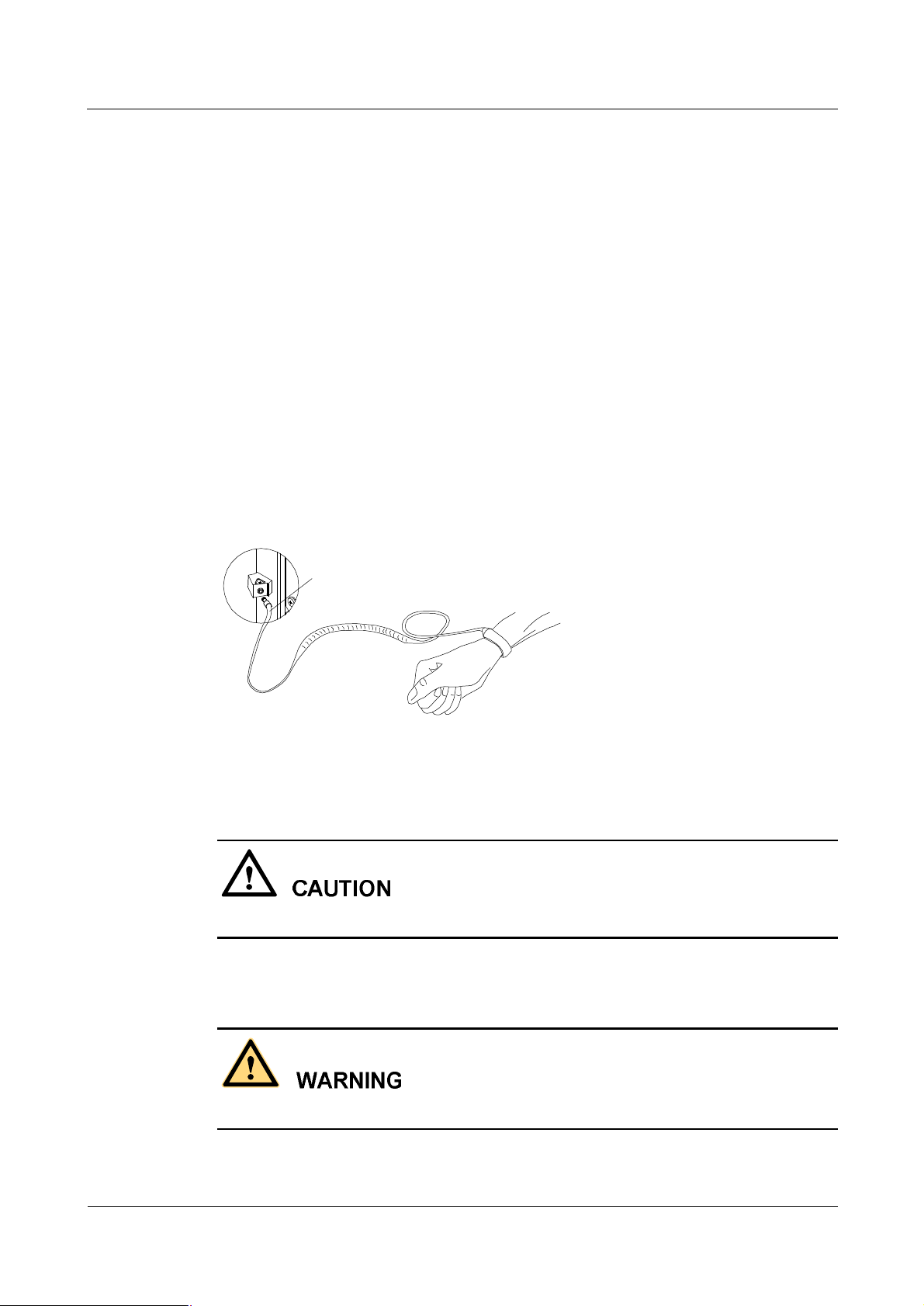
Figure 1 shows how to wear an anti-static wrist strap.
Figure 1 Wearing an anti-static wrist strap
Plug of anti-static wrist strap
3.8 Labels on Power Supply Cables
Before connecting the cables, check the labels on them.
3.9 Leakage of Current
To avoid large leakage of current, ground the equipment before powering it on.
6 Huawei Technologies Proprietary Issue 01 (2007-01-24)
Page 15

iSite BTS3006C
Maintenance Manual Safety Precautions
Before connecting the AC input power supply, connect the protection-grounding terminal of
the equipment housing to the earth. The purpose is to avoid the electric shock on human body
resulting from leakage of current. The leakage of current is caused by the EMI filter earth
capacitance of the equipment AC power supply input terminal and the Y capacitance of the
primary power supply.
3.10 Flammable Air
Do not place the equipment in an environment with flammable, explosive air or smog. Never
operate any digital equipment in this environment.
It is extremely dangerous to operate any digital equipment in this environment.
4 Microwave and Magnetic Field
4.1 Introduction
Antennas in service generate electromagnetic radiation. Standing too close to the antenna is
against the safety codes.
Only trained professionals can install and maintain antennas.
The radiation design of the equipment should meet the IEEE C95.1-1991 recommendation.
When working near a full-power transmitting antenna, keep the following safety regulations
in mind.
4.2 Definitions of Environment
There are two kinds of environment under electromagnetic radiation.
l
Controlled environment
In such areas, people are aware of the potential danger of the radio frequency radiation.
l
Uncontrolled environment
In such areas, people are unaware of the potential danger of the radio frequency radiation.
They cannot evade the radiation. The area may include living or working places.
4.3 Minimal Distance Formula
This section shows how to calculate the minimal safety distance.
Use the following formula to calculate the minimal safety distance from various antennas.
(G-L)
10
min
N10
=
r
The elements in the formula include:
Issue 01 (2007-01-24) Huawei Technologies Proprietary 7
4 W
OUT
P
Page 16
Safety Precautions
iSite BTS3006C
Maintenance Manual
l
R
is the minimal safety distance. Its unit is meter.
min
l
N is the number of frequency carriers.
l
P
is the output power of the frequency carrier. Its unit is W.
out
l
L is the loss from transmitting party to the receiving party. Its unit is dB.
l
G is the antenna gain. Its unit is dB.
l
W is the greatest field power density permitted. Its unit is W/m2.
In the uncontrolled environment, the greatest field power density permitted is f/150, in which
f is the frequency, and its unit is MHz. Its tested value is the mean value measured when the
testing time is over 30 minutes.
In the controlled environment, the greatest field power density permitted is f/30, and its tested
value is the mean value measured when the testing time is over 6 minutes.
Table 1 shows the minimal safety distance on the axial line of the antenna field calculated by
the above formula.
Table 1 Typical minimal safety distance
Frequency f (MHz) 1800
Frequency output power P
Loss from the transmitting party to the receiving party L (dBm) 5.5
Antenna gain G (dBm) 18
Number of frequency carriers N 2
Power density/uncontrolled environment W (W/m2) 12
Power density/controlled environment W (W/m2) 60
Uncontrolled environment r
Controlled environment r
4.4 Operation Codes
When operating on the high intensity radio frequency signal equipment, keep in mind that the
high-intensity microwave is harmful to human health.
(W) 40
out
(m) 3.1
min
(m) 1.4
min
5 Laser
8 Huawei Technologies Proprietary Issue 01 (2007-01-24)
Page 17
iSite BTS3006C
Maintenance Manual Safety Precautions
The laser beam inside optical fibers may injure your eyes.
When installing and maintaining optical fibers, keep your eyes away from them and avoid
looking at the optical fiber outlet.
6 High Temperature
The temperature of some equipment parts may be high. Do not touch the surface to avoid
being scalded.
When the equipment is running in the tropical environment, the temperature benchmark of the
parts is 45âC. In that case:
l
The temperature rise is within 30âC or the highest temperature is 75âC when the
equipment is running normally.
l
The temperature rise is within 55âC or the highest temperature is 100âC when a fault
occurs.
The temperature for radiator of the transmitter RF power amplifier and the power supply
radiator can reach the above-mentioned high temperature.
7 Working High above the Ground
7.1 General Operation
Prevent objects from falling, when working from a higher altitude.
Follow the local safety regulations when working from a higher altitude:
l
The workers should be trained.
l
Take care of the machines and tools at hand and prevent them from falling.
l
Put a tool back into the tool bag right after use.
l
Put on a helmet and safety belt.
l
Put on cold-proof clothes in cold areas beforehand.
Issue 01 (2007-01-24) Huawei Technologies Proprietary 9
Page 18
Safety Precautions
l
Check all the hoisting gears beforehand.
7.2 Safety Codes on Ladder Use
Check the ladder beforehand to make sure that the ladder is safe for use. Overweight on the
ladder is strictly prohibited.
You need to hold or secure the ladder in the following cases:
l
If the ladder slants over 5 m horizontally,
l
If the two legs of the ladder are over 3 m away, or
l
If the environment is dangerous.
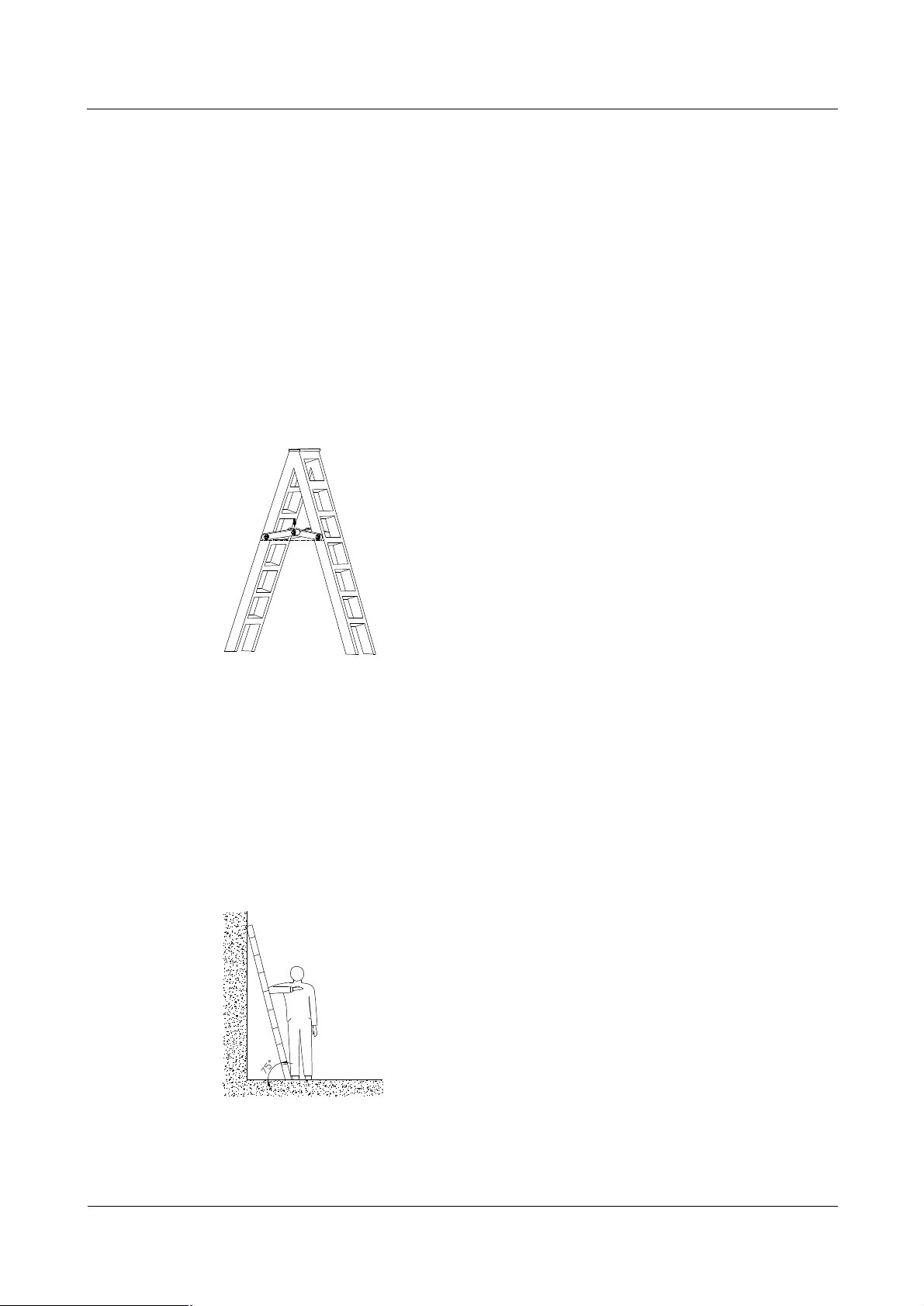
Be sure to spread A-shaped ladders fully, as shown in Figure 2.
Figure 2 Spread A-shaped ladder
iSite BTS3006C
Maintenance Manual
The slant of the ladder is 75â at best.
Measure the slant with the Angle Square or with arms, as shown in Figure 3.
When using the ladder, place the wider end of the ladder against the ground or take protective
measures on the base part of the ladder against skid.
Place the ladder against a stable and level ground. Never place a ladder on slippery objects
such as cartons and stones.
Figure 3 Ladder slant
When climbing the ladder,
10 Huawei Technologies Proprietary Issue 01 (2007-01-24)
Page 19
iSite BTS3006C
Maintenance Manual Safety Precautions
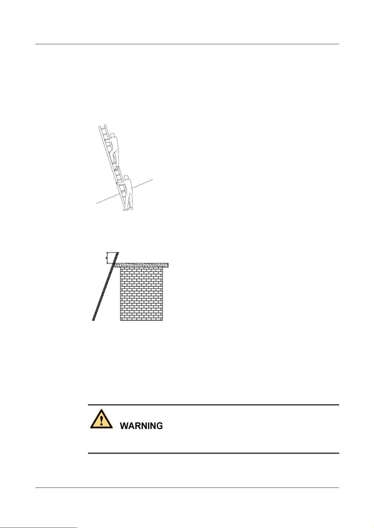
l
Make sure that the gravity center of your body is within the ladder range.
l
Keep both feet and at least one hand on the ladder.
l
Do not climb beyond highest fourth step.
To climb to a rooftop, the length of the ladder should be 1 meter higher than the eave, as
shown in Figure 5.
Figure 4 Using the long ladder in a safe way
Figure 5 Ladder placement when the ladder is 1 meter higher than the eave
8 Other Items
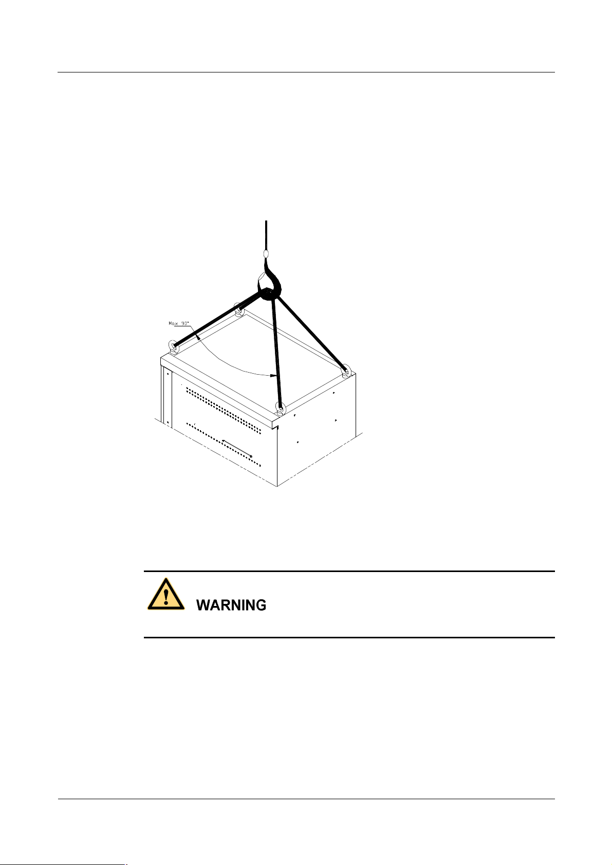
8.1 Weight Hoisting
Exclude access to the areas under the gib arm and the goods in suspension during weight
hoisting.
Comply with the following regulations:
Issue 01 (2007-01-24) Huawei Technologies Proprietary 11
Page 20
Safety Precautions
iSite BTS3006C
Maintenance Manual
l
The weight-hoisting workers must be trained and qualified.
l
The weight-hoisting tools must be functional and complete.
l
The weight-hoisting tools must be fixed securely onto a weight-bearing object or wall.
l
Use concise commands to avoid faulty operation.
l
Make sure that the included angle of the cables for hoisting the cabinet is within 90â to
prevent the cable from breaking.
Figure 6 Weight hoisting
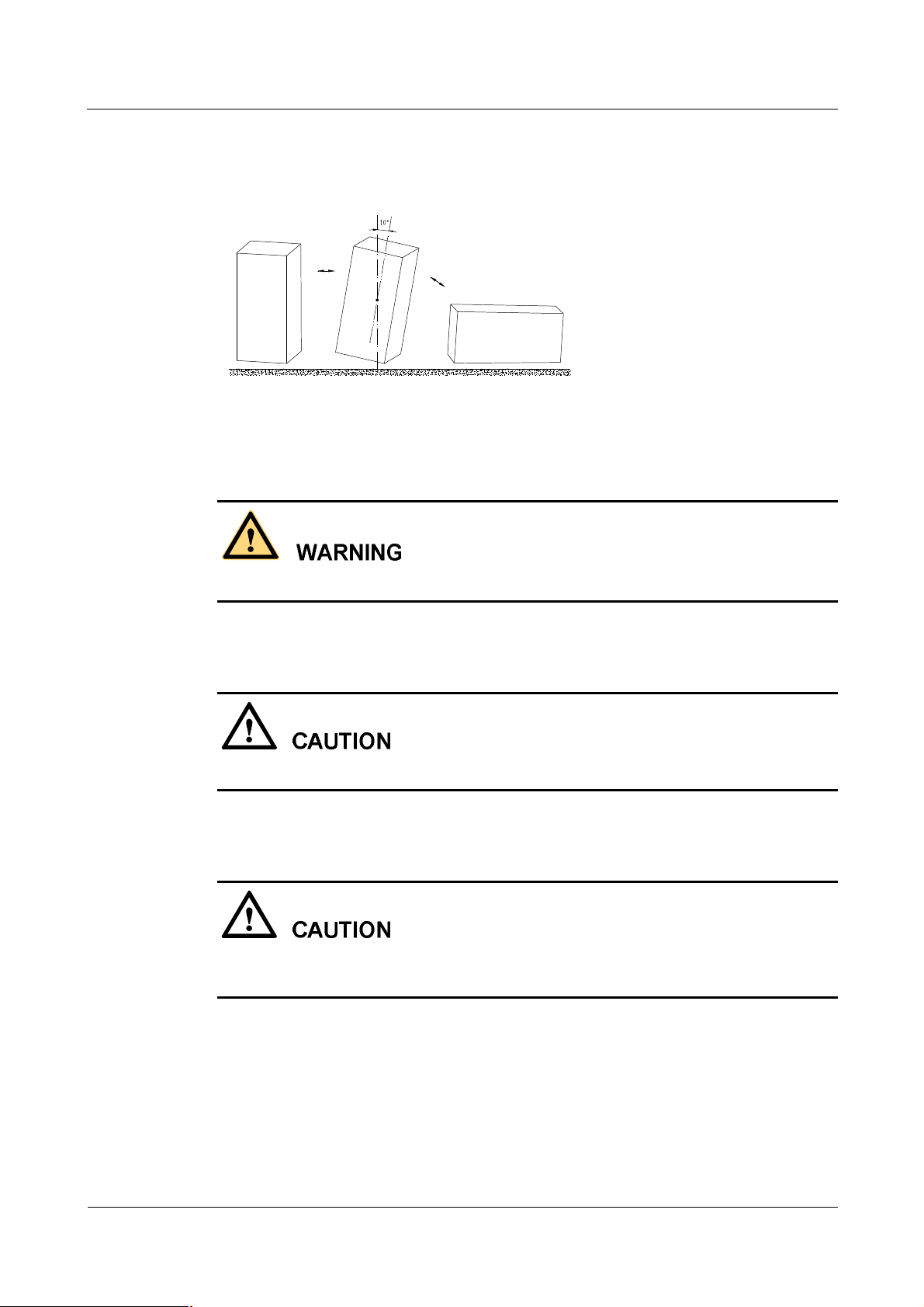
8.2 Heavy Object Portage
When carrying heavy objects such as the cabinets, be careful not to get bruised by them.
Two or three people are required to perform the following tasks:
l
Installing and maintaining BTS cabinets
l
Slanting, tilting, and erecting the cabinet
When the cabinet center of gravity slants over 10â, the cabinet may be off balance under
gravity.
12 Huawei Technologies Proprietary Issue 01 (2007-01-24)
Page 21
iSite BTS3006C
Maintenance Manual Safety Precautions
Figure 7 shows how to lay or erect a cabinet.
Figure 7 Laying or erecting a cabinet
8.3 Sharp Edge of Objects
When handling equipment, wear gloves for protection against sharp objects.
8.4 Binding of Signal Wires
Bind signal wires separately at least 150 mm from the cables of strong current or high voltage.
8.5 Having Companions in Maintenance and Commissioning
Ensure that there are qualified people for assistance during maintenance and commissioning
of the equipment.
Issue 01 (2007-01-24) Huawei Technologies Proprietary 13
Page 22

iSite BTS3006C
Maintenance Manual Contents
Contents
Safety Precautions.......................................................................................................................1
1 Overview....................................................................................................................................................1
1.1 Guide.................................................................................................................................................1
1.2 Symbols.............................................................................................................................................1
2 Toxic Articles..............................................................................................................................................2
2.1 Beryllium Oxide................................................................................................................................2
2.2 Hydrochloride....................................................................................................................................2
2.3 Hydrofluoride....................................................................................................................................3
3 Electrical Safety..........................................................................................................................................3
3.1 High Voltage......................................................................................................................................3
3.2 Power Cable......................................................................................................................................4
3.3 Fuse...................................................................................................................................................4
3.4 Tools.................................................................................................................................................4
3.5 Drilling Holes....................................................................................................................................4
3.6 Thunderstorm....................................................................................................................................5
3.7 Static Electricity................................................................................................................................5
3.8 Labels on Power Supply Cables.........................................................................................................6
3.9 Leakage of Current............................................................................................................................6
3.10 Flammable Air.................................................................................................................................7
4 Microwave and Magnetic Field....................................................................................................................7
4.1 Introduction.......................................................................................................................................7
4.2 Definitions of Environment................................................................................................................7
4.3 Minimal Distance Formula.................................................................................................................7
4.4 Operation Codes................................................................................................................................8
5 Laser...........................................................................................................................................................8
6 High Temperature........................................................................................................................................9
7 Working High above the Ground..................................................................................................................9
7.1 General Operation..............................................................................................................................9
7.2 Safety Codes on Ladder Use............................................................................................................10
8 Other Items...............................................................................................................................................11
8.1 Weight Hoisting...............................................................................................................................11
8.2 Heavy Object Portage......................................................................................................................12
Issue 01 (2007-01-24)
Huawei Technologies Proprietary
i
Page 23

iSite BTS3006C
Contents
8.3 Sharp Edge of Objects......................................................................................................................13
8.4 Binding of Signal Wires...................................................................................................................13
8.5 Having Companions in Maintenance and Commissioning.................................................................13
Maintenance Manual
About This Document................................................................................................................1
1 Preparations for Maintenance.............................................................................................1-1
1.1 Understanding the BTS Information......................................................................................................1-2
1.2 Preparing Tools and Spare Parts............................................................................................................1-2
2 Routine Maintenance...........................................................................................................2-1
2.1 Routine Maintenance Items...................................................................................................................2-2
2.1.1 Routine Maintenance Items for the Major Equipment..................................................................2-2
2.1.2 Routine Maintenance Items for the Auxiliary Equipment.............................................................2-3
2.1.3 Routine Maintenance Items for the Antenna System....................................................................2-4
2.2 Maintenance Guidelines to the Major Equipment..................................................................................2-4
2.2.1 Querying and Handling the Current Faults and Alarms.................................................................2-4
2.2.2 Call Test.....................................................................................................................................2-6
2.2.3 Short Message Test.....................................................................................................................2-7
2.2.4 Packet Data Service Test.............................................................................................................2-8
2.2.5 Checking the VSWR...................................................................................................................2-9
2.2.6 Cleaning the Fan Box..................................................................................................................2-9
2.2.7 Checking the Trunk Transmission...............................................................................................2-12
2.2.8 Checking the Equipment Wiring.................................................................................................2-12
2.3 Maintenance Guidelines to the Auxiliary Devices.................................................................................2-13
2.3.1 Checking the Alarm Collection Devices......................................................................................2-13
2.3.2 Testing the Grounding Resistance...............................................................................................2-13
2.4 Maintenance Guidelines to the Antenna System....................................................................................2-14
2.4.1 Checking the Tower...................................................................................................................2-14
2.4.2 Checking the Pole......................................................................................................................2-14
2.4.3 Checking the Antenna................................................................................................................2-14
2.4.4 Checking the Feeder...................................................................................................................2-16
2.5 BTS Routine Maintenance Record.......................................................................................................2-17
2.5.1 BTS Weekly Maintenance Record..............................................................................................2-17
2.5.2 BTS Monthly Maintenance Record.............................................................................................2-18
2.5.3 BTS Quarterly Maintenance Record...........................................................................................2-19
2.5.4 BTS Yearly Maintenance Record................................................................................................2-20
2.5.5 BTS Unexpected Fault Handling Record....................................................................................2-21
3 Emergency Maintenance......................................................................................................3-1
3.1 Overview of Emergency Maintenance...................................................................................................3-2
3.1.1 Application Scenarios..................................................................................................................3-2
3.1.2 Basic Principles of Emergency Maintenance................................................................................3-2
3.1.3 Points to Remember....................................................................................................................3-2
ii
Huawei Technologies Proprietary
Issue 01 (2007-01-24)
Page 24

iSite BTS3006C
Maintenance Manual Contents
3.2 Emergency Maintenance Procedures.....................................................................................................3-3
3.2.1 Emergency Maintenance Flowchart.............................................................................................3-3
3.2.2 Checking Services for Faults.......................................................................................................3-3
3.2.3 Locating the Causes....................................................................................................................3-3
3.2.4 Contacting Huawei......................................................................................................................3-4
3.2.5 Recovering Services....................................................................................................................3-5
3.2.6 Observing Recovered Services....................................................................................................3-5
3.2.7 Collecting Data...........................................................................................................................3-6
3.2.8 Performing Emergency Maintenance...........................................................................................3-6
3.3 Handling the Faults in an Individual BTS in Emergency Cases..............................................................3-6
3.3.1 Overview....................................................................................................................................3-6
3.3.2 Abnormal Power Supply.............................................................................................................3-6
3.3.3 Abnormal Transmission...............................................................................................................3-7
3.3.4 Data Mistakenly Modified on the BSC........................................................................................3-8
3.3.5 BSC Hardware Faults..................................................................................................................3-9
3.3.6 BSC Data Configuration Error.....................................................................................................3-9
3.3.7 Abnormal BTS Voltage Control..................................................................................................3-10
3.3.8 Abnormal BSC Clock.................................................................................................................3-11
3.4 Handling the Faults in Associated BTSs in Emergency Cases...............................................................3-11
3.4.1 Overview...................................................................................................................................3-11
3.4.2 Abnormal Power Supply............................................................................................................3-11
3.4.3 Abnormal Transmission..............................................................................................................3-12
3.4.4 Data Mistakenly Modified on the BSC.......................................................................................3-12
3.4.5 Services Interrupted in Associated BTSs.....................................................................................3-13
3.4.6 Optical Connection Error Between Combined Cabinets or Between Cabinet Groups...................3-13
3.4.7 BSC Data Configuration Error....................................................................................................3-14
3.4.8 Abnormal BTS Voltage Control..................................................................................................3-14
3.4.9 Abnormal BSC Clock.................................................................................................................3-14
3.5 Handling Cell Service Disruption in Emergency Cases.........................................................................3-15
3.5.1 Network Access Failure..............................................................................................................3-15
3.5.2 Calling Failure...........................................................................................................................3-15
3.5.3 Called Failure............................................................................................................................3-16
3.5.4 MSC Data Error.........................................................................................................................3-16
3.6 Handling the Alarms of Main Modules in Emergency Cases.................................................................3-17
3.6.1 Overview...................................................................................................................................3-17
3.6.2 Clock Reference Abnormal........................................................................................................3-17
3.6.3 Hardware Critical Alarm............................................................................................................3-18
3.6.4 Internal Power Alarm of the DMCM...........................................................................................3-19
3.6.5 Master Clock Alarm...................................................................................................................3-20
3.6.6 LAPD Alarm..............................................................................................................................3-20
3.6.7 DDRM Communication Alarm...................................................................................................3-21
3.6.8 Clock Critical Alarm..................................................................................................................3-22
Issue 01 (2007-01-24)
Huawei Technologies Proprietary
iii
Page 25

Contents
iSite BTS3006C
Maintenance Manual
3.6.9 Repeat Download of DDRM Version..........................................................................................3-23
3.6.10 Hardware Faults.......................................................................................................................3-23
3.6.11 Abnormal Channel Status.........................................................................................................3-24
3.6.12 VSWR Alarm...........................................................................................................................3-24
3.6.13 LNA Fault................................................................................................................................3-25
3.6.14 Abnormal SFPA/SFPB Sending or Receiving Alarm.................................................................3-25
3.6.15 SFPA or SFPB Local Alarm......................................................................................................3-26
3.6.16 SFPA or SFPB Remote Alarm...................................................................................................3-27
3.7 Data Backup and Restoration...............................................................................................................3-28
3.8 Maintenance Record............................................................................................................................3-28
3.8.1 Emergency Maintenance Note....................................................................................................3-28
3.8.2 Troubleshooting Record Table....................................................................................................3-30
4 Replacing Modules and Parts..............................................................................................4-1
4.1 Overview..............................................................................................................................................4-2
4.1.1 Replacing Parts in Different Situations........................................................................................4-2
4.1.2 Classification of the BTS3006C Modules and Parts.....................................................................4-2
4.2 Replacing Modules...............................................................................................................................4-3
4.2.1 General Procedure.......................................................................................................................4-3
4.2.2 Replacing the DMCM.................................................................................................................4-7
4.2.3 Replacing the DDRM.................................................................................................................4-11
4.2.4 Replacing the DDPM.................................................................................................................4-13
4.2.5 Replacing the DDCM.................................................................................................................4-15
4.2.6 Replacing the DSCM.................................................................................................................4-18
4.2.7 Replacing the DPSM..................................................................................................................4-20
4.2.8 Replacing the DSEM..................................................................................................................4-22
4.2.9 Replacing the DATM.................................................................................................................4-24
4.3 Replacing Parts....................................................................................................................................4-26
4.3.1 Replacing the Fan Box...............................................................................................................4-26
4.3.2 Replacing BTS3006C Antennas..................................................................................................4-29
4.3.3 Replacing the TMA....................................................................................................................4-33
4.4 Replacing Cables.................................................................................................................................4-37
4.4.1 Replacing an E1 Trunk Cable.....................................................................................................4-37
4.4.2 Replacing an SDH External Optical Cables................................................................................4-40
4.4.3 Replacing the AC/DC Power Cables...........................................................................................4-42
4.4.4 Replacing the Power Cable of the TMA......................................................................................4-46
4.4.5 Replacing the RF Interconnection Cable.....................................................................................4-48
4.4.6 Replacing the Combined Optical Cable......................................................................................4-50
4.4.7 Replacing the Alarm Cables.......................................................................................................4-52
4.4.8 Replacing the RF Jumper...........................................................................................................4-54
A Requirements for Antenna Spacing.................................................................................A-1
A.1 Omni-Directional Antenna...................................................................................................................A-2
iv
Huawei Technologies Proprietary
Issue 01 (2007-01-24)
Page 26

iSite BTS3006C
Maintenance Manual Contents
A.2 Directional Antennas............................................................................................................................A-3
B Engineering Labels for Antenna System..........................................................................B-1
B.1 Engineering Labels for Feeders............................................................................................................B-2
B.2 Explanation of the Jumper Engineering Label.......................................................................................B-3
C Glossary................................................................................................................................C-1
D Acronyms and Abbreviations...........................................................................................D-1
Index...........................................................................................................................................i-1
Issue 01 (2007-01-24)
Huawei Technologies Proprietary
v
Page 27

Page 28

iSite BTS3006C
Maintenance Manual Figures
Figures
Figure 1 Wearing an anti-static wrist strap......................................................................................................6
Figure 2 Spread A-shaped ladder..................................................................................................................10
Figure 3 Ladder slant...................................................................................................................................10
Figure 4 Using the long ladder in a safe way................................................................................................11
Figure 5 Ladder placement when the ladder is 1 meter higher than the eave..................................................11
Figure 6 Weight hoisting..............................................................................................................................12
Figure 7 Laying or erecting a cabinet...........................................................................................................13
Figure 2-1 Browse Real Time Alarm window.............................................................................................2-5
Figure 2-2 Module alarm information........................................................................................................2-6
Figure 2-3 Removing the fan box from the cabinet....................................................................................2-10
Figure 2-4 Installing the fan box...............................................................................................................2-11
Figure 3-1 Process of handling emergency maintenance.............................................................................3-3
Figure 3-2 Process of Huawei emergency service handling.........................................................................3-4
Figure 4-1 Replacing the modules..............................................................................................................4-4
Figure 4-2 Querying the board information................................................................................................4-6
Figure 4-3 Replacing the DMCM...............................................................................................................4-9
Figure 4-4 Replacing the DDRM..............................................................................................................4-12
Figure 4-5 Replacing the DDPM...............................................................................................................4-14
Figure 4-6 Replacing the DDCM..............................................................................................................4-16
Figure 4-7 Replacing the DSCM...............................................................................................................4-19
Figure 4-8 Replacing the DPSM...............................................................................................................4-21
Figure 4-9 Replacing the DSEM...............................................................................................................4-23
Figure 4-10 Replacing the DATM.............................................................................................................4-25
Figure 4-11 Replacing the fan box.............................................................................................................4-27
Figure 4-12 Replacing the BTS3006C antenna..........................................................................................4-31
Figure 4-13 Replacing the TMA................................................................................................................4-35
Issue 01 (2007-01-24)
Huawei Technologies Proprietary
vii
Page 29

Figures
iSite BTS3006C
Maintenance Manual
Figure 4-14 Replacing an E1 trunk cable...................................................................................................4-38
Figure 4-15 Replacing an SDH external optical cable................................................................................4-41
Figure 4-16 Replacing the power cable......................................................................................................4-44
Figure 4-17 Replacing the power cable of the TMA...................................................................................4-47
Figure 4-18 Replacing RF interconnection cables......................................................................................4-49
Figure 4-19 Replacing the combined optical cable.....................................................................................4-51
Figure 4-20 Replacing an alarm cable.......................................................................................................4-53
Figure 4-21 Replacing the RF jumper........................................................................................................4-55
Figure B-1 Feeder tag (for the transmit end)...............................................................................................B-2
Figure B-2 Feeder tag (for the receive end)................................................................................................B-3
Figure B-3 Jumper tag (for the transmit & receive end)..............................................................................B-4
viii
Huawei Technologies Proprietary
Issue 01 (2007-01-24)
Page 30

iSite BTS3006C
Maintenance Manual Tables
Tables
Table 1 Typical minimal safety distance.........................................................................................................8
Table 1-1 List of other devices...................................................................................................................1-3
Table 2-1 Routine maintenance items for the major equipment....................................................................2-2
Table 2-2 Routine maintenance items for the auxiliary equipment...............................................................2-3
Table 2-3 Routine maintenance items for the antenna system......................................................................2-4
Table 2-4 BTS Weekly Maintenance Record..............................................................................................2-17
Table 2-5 BTS Monthly Maintenance Record............................................................................................2-18
Table 2-6 BTS Quarterly Maintenance Record...........................................................................................2-19
Table 2-7 BTS Yearly Maintenance Record...............................................................................................2-20
Table 2-8 BTS Unexpected Fault Handling Record....................................................................................2-22
Table 3-1 On-site information record in emergency cases............................................................................3-3
Table 3-2 Modules and related module alarms that affect BTS services......................................................3-17
Table 4-1 Classification of the BTS3006C modules and parts.....................................................................4-2
Table 4-2 List of the modules.....................................................................................................................4-3
Table 4-3 E1 trunk cables..........................................................................................................................4-38
Table 4-4 Trunk cable...............................................................................................................................4-40
Table 4-5 AC/DC power cables.................................................................................................................4-43
Table 4-6 Power cable of the TMA............................................................................................................4-46
Table 4-7 RF interconnection cables between modules...............................................................................4-48
Table 4-8 Combined optical cable.............................................................................................................4-50
Table 4-9 Alarm cables..............................................................................................................................4-52
Table 4-10 RF jumper...............................................................................................................................4-54
Table A-1 Requirements for omni-directional antenna spacing....................................................................A-2
Table A-2 Requirements for directional antenna spacing.............................................................................A-3
Table B-1 Description of the feeder engineering labels...............................................................................B-2
Table B-2 Description of the jumper engineering labels..............................................................................B-3
Issue 01 (2007-01-24)
Huawei Technologies Proprietary
ix
Page 31

Tables
iSite BTS3006C
Maintenance Manual
x
Huawei Technologies Proprietary
Issue 01 (2007-01-24)
Page 32

iSite BTS3006C
Maintenance Manual Contents
Contents
About This Document................................................................................................................1
Issue 01 (2007-01-24)
Huawei Technologies Proprietary
i
Page 33

Page 34

iSite BTS3006C
Maintenance Manual About This Document
About This Document
Purpose
This manual describes the procedures for the BTS3006C maintenance.
Related Versions
The following table lists the versions of the product that is described in this document.
Product Name Version
iSite BTS3006C V300R005
Intended Audience
The manual is intended for BTS operators.
Organization
This document consists of four chapters and two appendixes. It is organized as follows:
Chapter Description
1 Preparations for
Maintenance
2 Routine
Maintenance
This chapter introduces the preparations that have to be made for
routine maintenance.
This chapter describes the BTS3006C routine maintenance items
and maintenance guidelines.
3 Emergency
Maintenance
4 Replacing
Modules and Parts
Issue 01 (2007-01-24)
This chapter describes the methods and procedures for emergency
maintenance on the BTS3006C.
This chapter describes the procedures for replacing modules, parts,
and cables.
Huawei Technologies Proprietary
1
Page 35

About This Document
iSite BTS3006C
Maintenance Manual
Chapter Description
A Requirements for
Antenna Spacing
B Engineering
Labels for Antenna
System
C Glossary Lists the glossary involved in this manual.
D Acronyms and
Abbreviations
Conventions
Symbol Conventions
The symbols that may be found in this document are defined as follows.
Symbol Description
This appendix lists the requirements for the installation spacing of
omni-directional antenna and directional antenna in different
situations.
This appendix lists the engineering labels for the antenna system.
Lists the acronyms and abbreviations involved in this manual.
General Conventions
Convention Description
Times New Roman Normal paragraphs are in Times New Roman.
Boldface
Indicates a hazard with a high level of risk that, if not avoided,
will result in death or serious injury.
Indicates a hazard with a medium or low level of risk which, if
not avoided, could result in minor or moderate injury.
Indicates a potentially hazardous situation that, if not avoided,
could cause equipment damage, data loss, and performance
degradation, or unexpected results.
Indicates a tip that may help you solve a problem or save time.
Provides additional information to emphasize or supplement
important points of the main text.
Names of files, directories, folders, and users are in
boldface. For example, log in as user root.
Italic Book titles are in italics.
Courier New
2
Huawei Technologies Proprietary
Terminal display is in Courier New.
Issue 01 (2007-01-24)
Page 36

iSite BTS3006C
Maintenance Manual About This Document
Command Conventions
Convention Description
Boldface
Italic Command arguments are in italics.
[ ] Items (keywords or arguments) in square brackets [ ] are
{ x | y | ... } Alternative items are grouped in braces and separated by
[ x | y | ... ] Optional alternative items are grouped in square brackets
{ x | y | ... } * Alternative items are grouped in braces and separated by
GUI Conventions
Convention Description
Boldface
The keywords of a command line are in boldface.
optional.
vertical bars. One is selected.
and separated by vertical bars. One or none is selected.
vertical bars. A minimum of one or a maximum of all can
be selected.
Buttons, menus, parameters, tabs, windows, and dialog titles
are in boldface. For example, click OK.
> Multi-level menus are in boldface and separated by the ">"
Keyboard Operation
Format Description
Key
Key 1+Key 2
Key 1, Key 2 Press the keys in turn. For example, pressing Alt, A means
Mouse Operation
Action Description
Click Select and release the primary mouse button without
signs. For example, choose File > Create > Folder.
Press the key. For example, press Enter and press Tab.
Press the keys concurrently. For example, pressing
Ctrl+Alt+A means the three keys should be pressed
concurrently.
the two keys should be pressed in turn.
moving the pointer.
Issue 01 (2007-01-24)
Huawei Technologies Proprietary
3
Page 37

About This Document
Action Description
Double-click Press the primary mouse button twice continuously and
Drag Press and hold the primary mouse button and move the
Update History
Updates between document versions are cumulative. Therefore, the latest document version
contains all updates made to previous versions.
Updates in Issue 01 (2007-01-24)
Initial commercial release.
iSite BTS3006C
Maintenance Manual
quickly without moving the pointer.
pointer to a certain position.
4
Huawei Technologies Proprietary
Issue 01 (2007-01-24)
Page 38

iSite BTS3006C
Maintenance Manual Contents
Contents
1 Preparations for Maintenance.............................................................................................1-1
1.1 Understanding the BTS Information........................................................................................................1-2
1.2 Preparing Tools and Spare Parts..............................................................................................................1-2
2 Routine Maintenance...........................................................................................................2-1
2.1 Routine Maintenance Items....................................................................................................................2-2
2.1.1 Routine Maintenance Items for the Major Equipment.....................................................................2-2
2.1.2 Routine Maintenance Items for the Auxiliary Equipment................................................................2-3
2.1.3 Routine Maintenance Items for the Antenna System.......................................................................2-4
2.2 Maintenance Guidelines to the Major Equipment....................................................................................2-4
2.2.1 Querying and Handling the Current Faults and Alarms...................................................................2-4
2.2.2 Call Test........................................................................................................................................2-6
2.2.3 Short Message Test........................................................................................................................2-7
2.2.4 Packet Data Service Test................................................................................................................2-8
2.2.5 Checking the VSWR......................................................................................................................2-9
2.2.6 Cleaning the Fan Box....................................................................................................................2-9
2.2.7 Checking the Trunk Transmission.................................................................................................2-12
2.2.8 Checking the Equipment Wiring...................................................................................................2-12
2.3 Maintenance Guidelines to the Auxiliary Devices...................................................................................2-13
2.3.1 Checking the Alarm Collection Devices........................................................................................2-13
2.3.2 Testing the Grounding Resistance.................................................................................................2-13
2.4 Maintenance Guidelines to the Antenna System.....................................................................................2-14
2.4.1 Checking the Tower......................................................................................................................2-14
2.4.2 Checking the Pole.........................................................................................................................2-14
2.4.3 Checking the Antenna...................................................................................................................2-14
2.4.4 Checking the Feeder.....................................................................................................................2-16
2.5 BTS Routine Maintenance Record.........................................................................................................2-17
2.5.1 BTS Weekly Maintenance Record.................................................................................................2-17
2.5.2 BTS Monthly Maintenance Record...............................................................................................2-18
2.5.3 BTS Quarterly Maintenance Record..............................................................................................2-19
2.5.4 BTS Yearly Maintenance Record..................................................................................................2-20
2.5.5 BTS Unexpected Fault Handling Record.......................................................................................2-21
Issue 01 (2007-01-24) Huawei Technologies Proprietary i
Page 39

iSite BTS3006C
Contents
Maintenance Manual
3 Emergency Maintenance......................................................................................................3-1
3.1 Overview of Emergency Maintenance.....................................................................................................3-2
3.1.1 Application Scenarios....................................................................................................................3-2
3.1.2 Basic Principles of Emergency Maintenance..................................................................................3-2
3.1.3 Points to Remember.......................................................................................................................3-2
3.2 Emergency Maintenance Procedures.......................................................................................................3-3
3.2.1 Emergency Maintenance Flowchart...............................................................................................3-3
3.2.2 Checking Services for Faults..........................................................................................................3-3
3.2.3 Locating the Causes.......................................................................................................................3-3
3.2.4 Contacting Huawei........................................................................................................................3-4
3.2.5 Recovering Services......................................................................................................................3-5
3.2.6 Observing Recovered Services.......................................................................................................3-5
3.2.7 Collecting Data..............................................................................................................................3-6
3.2.8 Performing Emergency Maintenance..............................................................................................3-6
3.3 Handling the Faults in an Individual BTS in Emergency Cases................................................................3-6
3.3.1 Overview.......................................................................................................................................3-6
3.3.2 Abnormal Power Supply................................................................................................................3-6
3.3.3 Abnormal Transmission.................................................................................................................3-7
3.3.4 Data Mistakenly Modified on the BSC...........................................................................................3-8
3.3.5 BSC Hardware Faults....................................................................................................................3-9
3.3.6 BSC Data Configuration Error.......................................................................................................3-9
3.3.7 Abnormal BTS Voltage Control.....................................................................................................3-10
3.3.8 Abnormal BSC Clock...................................................................................................................3-11
3.4 Handling the Faults in Associated BTSs in Emergency Cases.................................................................3-11
3.4.1 Overview......................................................................................................................................3-11
3.4.2 Abnormal Power Supply...............................................................................................................3-11
3.4.3 Abnormal Transmission................................................................................................................3-12
3.4.4 Data Mistakenly Modified on the BSC..........................................................................................3-12
3.4.5 Services Interrupted in Associated BTSs.......................................................................................3-13
3.4.6 Optical Connection Error Between Combined Cabinets or Between Cabinet Groups......................3-13
3.4.7 BSC Data Configuration Error......................................................................................................3-14
3.4.8 Abnormal BTS Voltage Control.....................................................................................................3-14
3.4.9 Abnormal BSC Clock...................................................................................................................3-14
3.5 Handling Cell Service Disruption in Emergency Cases...........................................................................3-15
3.5.1 Network Access Failure................................................................................................................3-15
3.5.2 Calling Failure..............................................................................................................................3-15
3.5.3 Called Failure...............................................................................................................................3-16
3.5.4 MSC Data Error...........................................................................................................................3-16
3.6 Handling the Alarms of Main Modules in Emergency Cases...................................................................3-17
3.6.1 Overview......................................................................................................................................3-17
3.6.2 Clock Reference Abnormal...........................................................................................................3-17
3.6.3 Hardware Critical Alarm...............................................................................................................3-18
ii Huawei Technologies Proprietary Issue 01 (2007-01-24)
Page 40

iSite BTS3006C
Maintenance Manual Contents
3.6.4 Internal Power Alarm of the DMCM.............................................................................................3-19
3.6.5 Master Clock Alarm......................................................................................................................3-20
3.6.6 LAPD Alarm................................................................................................................................3-20
3.6.7 DDRM Communication Alarm.....................................................................................................3-21
3.6.8 Clock Critical Alarm.....................................................................................................................3-22
3.6.9 Repeat Download of DDRM Version............................................................................................3-23
3.6.10 Hardware Faults.........................................................................................................................3-23
3.6.11 Abnormal Channel Status............................................................................................................3-24
3.6.12 VSWR Alarm.............................................................................................................................3-24
3.6.13 LNA Fault..................................................................................................................................3-25
3.6.14 Abnormal SFPA/SFPB Sending or Receiving Alarm....................................................................3-25
3.6.15 SFPA or SFPB Local Alarm........................................................................................................3-26
3.6.16 SFPA or SFPB Remote Alarm.....................................................................................................3-27
3.7 Data Backup and Restoration.................................................................................................................3-28
3.8 Maintenance Record..............................................................................................................................3-28
3.8.1 Emergency Maintenance Note......................................................................................................3-28
3.8.2 Troubleshooting Record Table.......................................................................................................3-30
4 Replacing Modules and Parts..............................................................................................4-1
4.1 Overview...............................................................................................................................................4-2
4.1.1 Replacing Parts in Different Situations...........................................................................................4-2
4.1.2 Classification of the BTS3006C Modules and Parts........................................................................4-2
4.2 Replacing Modules.................................................................................................................................4-3
4.2.1 General Procedure.........................................................................................................................4-3
4.2.2 Replacing the DMCM....................................................................................................................4-7
4.2.3 Replacing the DDRM...................................................................................................................4-11
4.2.4 Replacing the DDPM....................................................................................................................4-13
4.2.5 Replacing the DDCM...................................................................................................................4-15
4.2.6 Replacing the DSCM....................................................................................................................4-18
4.2.7 Replacing the DPSM....................................................................................................................4-20
4.2.8 Replacing the DSEM....................................................................................................................4-22
4.2.9 Replacing the DATM....................................................................................................................4-24
4.3 Replacing Parts.....................................................................................................................................4-26
4.3.1 Replacing the Fan Box..................................................................................................................4-26
4.3.2 Replacing BTS3006C Antennas....................................................................................................4-29
4.3.3 Replacing the TMA......................................................................................................................4-33
4.4 Replacing Cables...................................................................................................................................4-37
4.4.1 Replacing an E1 Trunk Cable........................................................................................................4-37
4.4.2 Replacing an SDH External Optical Cables...................................................................................4-40
4.4.3 Replacing the AC/DC Power Cables.............................................................................................4-42
4.4.4 Replacing the Power Cable of the TMA........................................................................................4-46
4.4.5 Replacing the RF Interconnection Cable.......................................................................................4-48
Issue 01 (2007-01-24) Huawei Technologies Proprietary iii
Page 41

Contents
iSite BTS3006C
Maintenance Manual
4.4.6 Replacing the Combined Optical Cable.........................................................................................4-50
4.4.7 Replacing the Alarm Cables..........................................................................................................4-52
4.4.8 Replacing the RF Jumper..............................................................................................................4-54
iv Huawei Technologies Proprietary Issue 01 (2007-01-24)
Page 42

iSite BTS3006C
Maintenance Manual Figures
Figures
Figure 2-1 Browse Real Time Alarm window...............................................................................................2-5
Figure 2-2 Module alarm information..........................................................................................................2-6
Figure 2-3 Removing the fan box from the cabinet......................................................................................2-10
Figure 2-4 Installing the fan box.................................................................................................................2-11
Figure 3-1 Process of handling emergency maintenance...............................................................................3-3
Figure 3-2 Process of Huawei emergency service handling...........................................................................3-4
Figure 4-1 Replacing the modules................................................................................................................4-4
Figure 4-2 Querying the board information..................................................................................................4-6
Figure 4-3 Replacing the DMCM.................................................................................................................4-9
Figure 4-4 Replacing the DDRM................................................................................................................4-12
Figure 4-5 Replacing the DDPM.................................................................................................................4-14
Figure 4-6 Replacing the DDCM................................................................................................................4-16
Figure 4-7 Replacing the DSCM.................................................................................................................4-19
Figure 4-8 Replacing the DPSM.................................................................................................................4-21
Figure 4-9 Replacing the DSEM.................................................................................................................4-23
Figure 4-10 Replacing the DATM...............................................................................................................4-25
Figure 4-11 Replacing the fan box..............................................................................................................4-27
Figure 4-12 Replacing the BTS3006C antenna............................................................................................4-31
Figure 4-13 Replacing the TMA.................................................................................................................4-35
Figure 4-14 Replacing an E1 trunk cable.....................................................................................................4-38
Figure 4-15 Replacing an SDH external optical cable..................................................................................4-41
Figure 4-16 Replacing the power cable.......................................................................................................4-44
Figure 4-17 Replacing the power cable of the TMA....................................................................................4-47
Figure 4-18 Replacing RF interconnection cables........................................................................................4-49
Figure 4-19 Replacing the combined optical cable.......................................................................................4-51
Figure 4-20 Replacing an alarm cable.........................................................................................................4-53
Issue 01 (2007-01-24) Huawei Technologies Proprietary v
Page 43

iSite BTS3006C
Figures
Figure 4-21 Replacing the RF jumper.........................................................................................................4-55
Maintenance Manual
vi Huawei Technologies Proprietary Issue 01 (2007-01-24)
Page 44

iSite BTS3006C
Maintenance Manual Tables
Tables
Table 1-1 List of other devices.....................................................................................................................1-3
Table 2-1 Routine maintenance items for the major equipment.....................................................................2-2
Table 2-2 Routine maintenance items for the auxiliary equipment.................................................................2-3
Table 2-3 Routine maintenance items for the antenna system........................................................................2-4
Table 2-4 BTS Weekly Maintenance Record...............................................................................................2-17
Table 2-5 BTS Monthly Maintenance Record..............................................................................................2-18
Table 2-6 BTS Quarterly Maintenance Record............................................................................................2-19
Table 2-7 BTS Yearly Maintenance Record.................................................................................................2-20
Table 2-8 BTS Unexpected Fault Handling Record......................................................................................2-22
Table 3-1 On-site information record in emergency cases.............................................................................3-3
Table 3-2 Modules and related module alarms that affect BTS services........................................................3-17
Table 4-1 Classification of the BTS3006C modules and parts.......................................................................4-2
Table 4-2 List of the modules.......................................................................................................................4-3
Table 4-3 E1 trunk cables............................................................................................................................4-38
Table 4-4 Trunk cable.................................................................................................................................4-40
Table 4-5 AC/DC power cables...................................................................................................................4-43
Table 4-6 Power cable of the TMA..............................................................................................................4-46
Table 4-7 RF interconnection cables between modules................................................................................4-48
Table 4-8 Combined optical cable...............................................................................................................4-50
Table 4-9 Alarm cables...............................................................................................................................4-52
Table 4-10 RF jumper.................................................................................................................................4-54
Issue 01 (2007-01-24) Huawei Technologies Proprietary vii
Page 45

Page 46

iSite BTS3006C
Maintenance Manual 1 Preparations for Maintenance
1 Preparations for Maintenance
About This Chapter
The following table lists the sections of this chapter.
Section Description
1.1 Understanding the BTS
Information
1.2 Preparing Tools and Spare
Parts
Introduces the basic information that maintenance
engineers need to learn before the maintenance.
Describes the tools and devices that you need to prepare
for maintenance.
Issue 01 (2007-01-24) Huawei Technologies Proprietary 1-1
Page 47

1 Preparations for Maintenance
1.1 Understanding the BTS Information
Before carrying out related maintenance tasks, familiarize yourself with the following
information related to the BTS:
l
Current faults and alarms
l
Hardware configuration
l
Software version
l
Transmission and networking
l
TS consolidation equipment, if any
l
Local environment
l
Spare parts
1.2 Preparing Tools and Spare Parts
iSite BTS3006C
Maintenance Manual
Prepare the following maintenance tools and parts:
l
Frequency test device
The frequency test device consists of a frequency generator, a spectrum analyzer, and
various connectors and cables.
A frequency tester is mandatory.
l
Power test device
The power test device is used to measure and analyze the output power. The output
power determines the effect of downlink coverage.
A power meter is mandatory.
l
Antenna and feeder test device
The antenna and feeder test device is used to measure the standing wave ratio, to return
loss and cable insertion loss, and to locate faults.
The Site Master is mandatory.
l
Other devices
1-2 Huawei Technologies Proprietary Issue 01 (2007-01-24)
Page 48

iSite BTS3006C
Maintenance Manual 1 Preparations for Maintenance
Table 1-1 lists other devices used in routine maintenance.
Table 1-1 List of other devices
l
Three Phillips screwdrivers (4', 6', and 8')
l
Three straight screwdrivers (4', 6', and 8')
l
Fastening Tools
Universal
Four adjustable wrenches (6', 8', 10', and 12')
l
A set of combination wrenches (17', and 19')
l
A set of inner hexagon spanners
Tools
l
Small Tools
A pair of sharp nose pliers (8')
l
A pair of pincer pliers (8')
Auxiliary Means
Electric soldering iron
Issue 01 (2007-01-24) Huawei Technologies Proprietary 1-3
Page 49

Page 50

iSite BTS3006C
Maintenance Manual 2 Routine Maintenance
2 Routine Maintenance
About This Chapter
The following table lists the sections of this chapter.
Section Description
2.1 Routine Maintenance
Items
2.2 Maintenance Guidelines to
the Major Equipment
2.3 Maintenance Guidelines to
the Auxiliary Devices
2.4 Maintenance Guidelines to
the Antenna System
2.5 BTS Routine Maintenance
Record
Introduces the routine maintenance items.
Describes the guidelines to routine maintenance on the
major equipment of the BTS3006C.
Describes the guidelines to routine maintenance on the
auxiliary devices of the BTS3006C.
Describes the guidelines to routine maintenance on the
antenna system of the BTS3006C.
Lists the BTS3006C Routine Maintenance Record.
Issue 01 (2007-01-24) Huawei Technologies Proprietary 2-1
Page 51

iSite BTS3006C
2 Routine Maintenance
Maintenance Manual
2.1 Routine Maintenance Items
According to the actual conditions, select the following maintenance items:
l
Routine Maintenance Items for the Major Equipment
l
Routine Maintenance Items for the Auxiliary Equipment
l
Routine Maintenance Items for the Antenna System
2.1.1 Routine Maintenance Items for the Major Equipment
Table 2-1 lists the routine maintenance items for the major equipment.
Table 2-1 Routine maintenance items for the major equipment
Maintenance Item Operating
Reference
Frequency
Querying and
handling current
faults and alarms
Each time site
maintenance
is performed
Section 2.2.1 "Querying and Handling the Current
Faults and Alarms"
Call test Every month Section 2.2.2 "Call Test"
Short message test Every month Section 2.2.3 "Short Message Test"
Packet Data Service
Every month Section 2.2.4 "Packet Data Service Test"
Test
Checking the Tx
power
Each time site
maintenance
The transmit power of the DDRM is consistent
with that configured in the BSC.
is performed
Checking the VSWR Each time site
Section 2.2.5 "Checking the VSWR"
maintenance
is performed
Checking the
exterior of the
cabinet
Every month
l
The battery capacity meets the requirements and
the battery is correctly connected.
l
The performance parameters of the rectifier meet
the requirements.
Checking the lock
Every month
and door of the
cabinet
Cleaning the cabinet Every month
l
The lock is functional.
l
The door is easy to open and close.
l
The cabinet surface is clean.
l
The subracks are not dusty.
Cleaning the fan box Every year If there is too much dust on the surface of the fan
box or inside the fan box, clean the fan box.
For details, refer to section 2.2.6 "Cleaning the Fan
Box."
2-2 Huawei Technologies Proprietary Issue 01 (2007-01-24)
Page 52

iSite BTS3006C
Maintenance Manual 2 Routine Maintenance
Maintenance Item Operating
Reference
Frequency
Checking the
module running
status
Every week The module indicators are normal.
For the status and meaning of module indicators,
refer to the iSite BTS3006C Hardware Description
Manual.
Checking the fan Every week The fan is operating normal, without abnormal
sound.
Checking trunk
Every month Section 2.2.7 "Checking the Trunk Transmission"
transmission
Checking equipment
Every month Section 2.2.8 "Checking the Equipment Wiring"
wiring
Checking the
lightning protector
Every month Check that the lightning protector of the DC/AC
power supply is operational.
of the power supply
2.1.2 Routine Maintenance Items for the Auxiliary Equipment
Table 2-2 lists the maintenance items for the auxiliary equipment.
Table 2-2 Routine maintenance items for the auxiliary equipment
Maintenance
Item
Checking alarm
collection devices
Checking the
Operating
Reference
Frequency
Every quarter Section 2.3.1 "Checking the Alarm Collection
Devices"
Every quarter Ensure that the grounding is normal.
grounding status of
the equipment
Testing the
grounding
resistance
Every year Measure the grounding resistance with a ground
resistance meter. Conduct the test before the rainy
season. The grounding resistance should be less than
10 ohms.
Checking the
battery
Every year
l
The battery capacity passes the check and the
battery is correctly connected.
l
The performance parameters of the rectifier pass
the check.
Issue 01 (2007-01-24) Huawei Technologies Proprietary 2-3
Page 53

iSite BTS3006C
2 Routine Maintenance
Maintenance Manual
2.1.3 Routine Maintenance Items for the Antenna System
Table 2-3 lists the maintenance items for the antenna system.
Table 2-3 Routine maintenance items for the antenna system
Maintenance
Item
Checking the
tower
Checking the
pole
Checking the
antenna
Checking the
feeder
Operation Frequency Remarks Reference
Every quarter Section 2.4.1
Every quarter Section 2.4.2
Every month Section 2.4.3
Every month
Carry out a
comprehensive
check when a
strong wind (force
8 and above), an
earthquake, or any
destructive accident
happens.
"Checking the Tower"
"Checking the Pole"
"Checking the
Antenna"
Section 2.4.4
"Checking the
Feeder"
2.2 Maintenance Guidelines to the Major Equipment
2.2.1 Querying and Handling the Current Faults and Alarms
Procedure
Step 1 Choose Start > Task > Alarm > Browse Real Time Alarm.
Pay attention to the recent history alarms.
To query the current faults and alarms, do as follows:
2-4 Huawei Technologies Proprietary Issue 01 (2007-01-24)
Page 54

iSite BTS3006C
Maintenance Manual 2 Routine Maintenance
The Browse Real Time Alarm window is displayed, as shown in Figure 2-1.
You can view all the current alarm information, including the node type, node ID, node name,
BAM ID, module ID, alarm type, alarm ID, and alarm name.
Figure 2-1 Browse Real Time Alarm window
Step 2 Query alarm information of a specific module as follows:
1. Choose Start > Task > BTS Maintenance.
2. Select Site > Board, and double-click Board Management.
The Board Maintenance dialog box is displayed.
3. Right-click the module to be viewed and choose Board Alarm from the shortcut menu.
4. Click the red square.
Issue 01 (2007-01-24) Huawei Technologies Proprietary 2-5
Page 55

2 Routine Maintenance
Figure 2-2 Module alarm information
iSite BTS3006C
Maintenance Manual
The detailed alarm information is display on the right of the window, as shown in
Figure 2-2.
Each square in the left pane of the window represents an alarm. Green indicates normal, and red
indicates an alarm.
5. The TRU module is located in the DDRM module.
Step 3 Rectify the faults by following the given suggestions.
----End
Reference Standards
The test results must meet the following conditions:
l
No alarms occur in hardware, environment, trunk transmission, or power supply.
l
The collected traffic statistics results are within the normal range.
To query alarms and traffic statistics results on the Operation and Maintenance Center (OMC) client,
refer to the BSS online help.
2.2.2 Call Test
This section describes the call test and its reference standards.
Procedure
To test the call service, do as follows:
2-6 Huawei Technologies Proprietary Issue 01 (2007-01-24)
Page 56

iSite BTS3006C
Maintenance Manual 2 Routine Maintenance
Step 1 Conduct a conversation test.
1. Power on the legal test MS, which is located in the coverage area of the tested BTS.
2. Use the test MS to call another MS or a fixed phone.
3. Use another MS or a fixed phone to call the test MS.
Step 2 Conduct a coverage test.
Select proper roads in the coverage area of the BTS to test the coverage influence, and then
record the test results.
Step 3 Conduct a handover test.
1. Power on the test MS defined legally within the coverage area of the BTS to be tested.
2. Use the test MS to make a call to another MS or a fixed telephone.
3. Move the test MS to another sector or cell.
4. Move the test MS back to the sector to be tested and end the call.
5. Use another MS or a fixed telephone to make a call to the test MS.
6. Move the test MS to another sector or cell.
----End
Reference Standards
l
Conversation test
The test results must meet the following conditions:
− The test MS can normally originates or terminates calls.
− The conversation between MSs is normal and the voice is clear.
− The call between the test MS and a fixed phone succeeds. The conversation between
the test MS and the fixed phone is normal and the voice is clear.
l
Coverage test
The test results must comply with the engineering design.
l
Handover test
When the MS is moving to the target sector or cell, the voice transmission should be
continuous and clear.
2.2.3 Short Message Test
This section describes the short message test and its reference standards.
Procedure
To test the short message service, do as follows:
Step 1 Conduct a short message service (SMS) test as follows:
1. Power on a registered test MS within the coverage area of the BTS to be tested.
2. Use the test MS to send short messages to other MSs.
3. Use other MSs to send short messages to the test MS.
4. Send short messages to the test MS when the test MS is in a call.
Step 2 Conduct a coverage test.
Issue 01 (2007-01-24) Huawei Technologies Proprietary 2-7
Page 57

2 Routine Maintenance
Select proper roads in the coverage area of the BTS to test coverage effect and record the test
results.
Step 3 Conduct a handover test as follows:
1. Power on a registered test MS within the coverage area of the BTS to be tested.
2. Use the test MS to send short messages to other MSs when the test MS is moving at the
edge of two neighboring cells.
3. Use other MSs to send short messages to the test MS when the test MS is moving at the
edge of two neighboring cells.
----End
Reference Standards
l
Short message test
The test MS normally receives and sends short messages.
l
Coverage test
The test results comply with the engineering design.
l
Handover test
The test MS receives and sends short messages normally during the handover.
iSite BTS3006C
Maintenance Manual
2.2.4 Packet Data Service Test
This section describes the procedure for testing packet data services and the test reference
standards.
Procedure
To test the packet data service, do as follows:
Step 1 Conduct a packet data service test as follows:
1. In the coverage area of the BTS to be tested, power on a registered test MS that supports
GPRS and MMS services.
2. Use the test MS to load data.
3. Use the test MS to browse a WAP website.
4. Use the test MS to receive an MMS or email from other MSs.
5. Use the test MS to send an MMS or email to other MSs.
Step 2 Conduct a coverage test.
Select proper roads in the coverage area of the BTS to test the coverage effect and record the
test results.
----End
Reference Standards
l
Packet data services test
− The test MS can browse and download data normally.
− The test MS can send or receive an MMS or an email to or from other MSs.
2-8 Huawei Technologies Proprietary Issue 01 (2007-01-24)
Page 58

iSite BTS3006C
Maintenance Manual 2 Routine Maintenance
l
Coverage test
The test results comply with the engineering design.
2.2.5 Checking the VSWR
This section describes the procedure for checking the Voltage Standing Wave Ratio (VSWR)
and the reference standards.
Procedure
To check the VSWR, do as follows:
Step 1 Check the alarm indicators VSWRA and VSWRB on the DDPM to see whether there is a
VSWR alarm.
You can also check whether there is a VSWR alarm on the Site Maintenance Terminal
System.
Step 2 If a VSWR alarm occurs, use an antenna analyzer to test the VSWR on site.
In normal conditions, the VSWR is smaller than 1.5.
Before conducting the VSWR test, prepare the jumper and the spare parts and adjust the analyzer before
conducting the VSWR test.
----End
Reference Standards
There is no VSWR alarm on the Site Maintenance Terminal System.
2.2.6 Cleaning the Fan Box
To ensure the long-term stability of the equipment, Huawei recommends that all fan boxes
should be cleaned once every year.
The replacement of a fan box seriously affects the heat dissipation of the system. Therefore,
Huawei recommends that you should replace the fan box quickly. If the replacement takes a
long time, the module may be damaged because of overhigh temperature.
Before replacing a fan box, disconnect the cable of the fan box and wait until the fan stops
running.
Procedure
To clean the fan box, do as follows:
Step 1 Use the tools such as clean cloth, antistatic brush, and cleaner to clean the spare parts of the
fan box.
Issue 01 (2007-01-24) Huawei Technologies Proprietary 2-9
Page 59

2 Routine Maintenance
Step 2 Open the front door of the BTS3006C cabinet.
Step 3 Disconnect the cable of the fan box on the DDRM panel.
Step 4 Use a cross screwdriver to loosen the two screws that fix the fan box.
Step 5 Remove the fan box from the cabinet, as shown in Figure 2-3.
1. Press the spring piece in the front of the fan box.
2. Hold the fan box and remove the pothook of the fan box from the hanging pole of the
Figure 2-3 Removing the fan box from the cabinet
iSite BTS3006C
Maintenance Manual
Each DDRM module of the BTS3006C is configured with a fan box. The DDRM module supplies
power to fan boxes through cables.
The front part of the fan box is disconnected from the bottom of the cabinet.
cabinet.
2-10 Huawei Technologies Proprietary Issue 01 (2007-01-24)
Page 60

iSite BTS3006C
Maintenance Manual 2 Routine Maintenance
Step 6 Install the clean fan box on the cabinet, as shown in Figure 2-4.
1. Determine the position where the fan box should be installed on the DDRM.
2. Hold the notch of the fan and hook the sheet metal at the rear of the fan up to the beam
under the installed DDRM.
3. Rotate the fan clockwise until the leaf spring on the front side of the fan is securely fixed
to the sheet metal at the bottom of the cabinet.
Figure 2-4 Installing the fan box
Step 7 Tighten the screws that fix the fan box.
Step 8 Connect the cable of the fan box on the DDRM panel.
Step 9 Perform Step 4 through Step 8 to replace other fan boxes until all the fan boxes have been
replaced.
Step 10 Use tools such as clean cloth, antistatic brush, and cleaner to clean the fan boxes that have
been removed from the cabinet.
These fan boxes are used as spare fan boxes.
----End
Issue 01 (2007-01-24) Huawei Technologies Proprietary 2-11
Page 61

2 Routine Maintenance
Reference Standards
There is no dust in the fan boxes.
2.2.7 Checking the Trunk Transmission
This section describes the procedure for checking the trunk transmission and the reference
standards.
Procedure
To check the trunk transmission, do as follows:
Step 1 Ensure that there is no transmission alarm displayed on the Site Maintenance Terminal
System.
Step 2 Ensure that the trunk cable connector connects well.
Step 3 Ensure that the trunk cable plug is in good condition.
Step 4 Ensure that the trunk cable is not damaged or broken.
Step 5 Ensure that the labels on both ends of the trunk cable are clear.
iSite BTS3006C
Maintenance Manual
----End
Reference Standards
No alarms relevant to the transmission system are reported.
2.2.8 Checking the Equipment Wiring
This section describes the procedure for checking the equipment wiring and the reference
standards.
Procedure
To check the equipment wiring, do as follows:
Step 1 Ensure that the plugs of the unused power cables are wrapped by a plastic cover.
This is to avoid a short circuit.
Step 2 Ensure that there are legible labels on both ends of the cable.
Step 3 Ensure that there are extra cables left near the plug.
Step 4 Check RF cable connectors to avoid abnormal VSWR caused by loose contact.
Step 5 Ensure that RF jumpers are routed by layers and sectors.
Step 6 Ensure that the horizontal part of the RF cable is placed in the cabling trough.
Step 7 Ensure that the RF jumpers are placed in parallel straight to the junction between the cabinet
and the feeder.
Step 8 Ensure that the jumpers are in good condition.
----End
2-12 Huawei Technologies Proprietary Issue 01 (2007-01-24)
Page 62

iSite BTS3006C
Maintenance Manual 2 Routine Maintenance
Reference Standards
The check results must meet the following standards:
l
The cables are bundled neatly and tightly. Cable ties are evenly spaced in the same
direction.
l
Cable layout facilitates maintenance and future capacity expansion.
2.3 Maintenance Guidelines to the Auxiliary Devices
2.3.1 Checking the Alarm Collection Devices
This section describes how to check the alarm collection devices and the reference standards.
Procedure
To check the alarm collection devices, do as follows:
Step 1 Check whether the following alarm collection devices are operating normally:
l
Temperature and humidity sensor
l
Fire alarm sensor
l
Anti-theft sensor
Step 2 Simulate changes in environment variations and check whether alarms are reported on the Site
Maintenance Terminal System.
----End
Reference Standards
The environment alarm information can be collected.
2.3.2 Testing the Grounding Resistance
This section describes the procedure for testing the grounding resistance and the reference
standards.
Procedure
Measure the grounding resistance with the ground resistance meter.
Reference Standards
The grounding resistance must be less than 10 ohms or meet the local engineering design.
Issue 01 (2007-01-24) Huawei Technologies Proprietary 2-13
Page 63

iSite BTS3006C
2 Routine Maintenance
Maintenance Manual
2.4 Maintenance Guidelines to the Antenna System
2.4.1 Checking the Tower
This section describes the procedure for checking the tower and the reference standards.
Procedure
To check the tower, do as follows:
Step 1 Ensure that there is no damage or sinking at the base of the tower.
Step 2 Measure the height and verticality of the tower.
Step 3 Ensure that the mechanical bolts are connected tightly.
Step 4 Check anti-rust and anti-corrosion conditions.
----End
Reference Standards
For details, refer to chapter 5 "Checking Installation" in the iSite BTS3006C Hardware
Installation Manual.
2.4.2 Checking the Pole
Procedure
To check the pole, do as follows:
Step 1 Check the installation of pole fasteners.
Step 2 Check the stress resistivity of the pole, staying wires and anchors.
Step 3 Check the verticality of the pole.
Step 4 Check anti-corrosion and anti-rust conditions.
----End
Reference Standards
For details, refer to chapter 9 "Checking Installation" in the iSite BTS3006C Hardware
Installation Manual.
2.4.3 Checking the Antenna
Procedure
To check the antenna, do as follows:
Step 1 Ensure that the antenna is protected within the coverage area of the lightning rod.
2-14 Huawei Technologies Proprietary Issue 01 (2007-01-24)
Page 64

iSite BTS3006C
Maintenance Manual 2 Routine Maintenance
Generally, the coverage area refers to the area that falls within the angle of 45° from the top of
the lightning rod. In areas prone to thunderstorms, the coverage area is reduced to an area that
falls within the angle of 30° from the top of the lightning rod.
Step 2 Ensure that the antenna stand is safely installed on the tower or the rooftop.
Step 3 If the BTS is installed with the omni-directional antenna, check the antenna according to the
omni-directional antenna standards stated in "Reference Standards."
Step 4 If the BTS is installed with the directional antenna, check the antenna according to the
directional antenna standards stated in "Reference Standards."
----End
Reference Standards
The check results of the omni-directional antenna must meet the following standards:
l
The top of the antenna sheathing is high or slightly higher than the stand top.
l
The omni-directional antennas stand upright with an error less than !2°.
l
The length of the antenna outside the tower platform is equal to or greater than 2 m.
l
The horizontal distance between the omni-directional antenna and the antenna lightning
rod is equal to or greater than 2.5 m.
l
For the requirements for the antenna spacing, refer to Appendix A "Requirements for
Antenna Spacing."
l
When two antennas are installed horizontally, the horizontal spacing between the
transmit and the receive antennas is equal to or greater than 5 m.
l
When two antennas are installed vertically, the vertical spacing between the transmit and
the receive antennas are equal to or greater than 0.2 m.
l
According to the diversity Rx requirement of the omni-directional antenna, the
horizontal spacing between the transmit and the receive antennas must be equal to or
greater than 4 m.
The check results of the directional antenna must meet the following standards:
l
The error of the azimuth angle is smaller than or equal to !5° and that of the pitch angle
is smaller than or equal to !0.5°.
l
The antennas are free from interference from the tower structure in the forward direction.
The length of the antenna outside the tower platform is equal to or greater than 1 m.
l
For the requirements for the antenna spacing, refer to Appendix A "Requirements for
Antenna Spacing."
l
The horizontal spacing between the transmit and the receive antennas in the same sector
is equal to or greater than 3 m in a horizontal installation.
l
The vertical spacing between the transmit and the receive antennas in the same sector is
equal to or greater than 0.2 m in a vertical installation.
l
The horizontal spacing between the transmit and the receive antennas in different sectors
is equal to or greater than 0.2 m.
l
According to the diversity Rx requirement of the directional antenna, the horizontal
spacing between the transmit and the receive antennas must be equal to or greater than 4
m.
Issue 01 (2007-01-24) Huawei Technologies Proprietary 2-15
Page 65

2 Routine Maintenance
2.4.4 Checking the Feeder
Procedure
To check the feeder, do as follows:
Step 1 Ensure that the feeder and the jumper are labeled as required.
Step 2 Ensure that the feeder is not folded or twisted and that there is no naked cable.
Step 3 Check the feeder fixing clips.
Step 4 Check the feeder connectors.
Step 5 Ensure that the feeder is connected properly and that the sectors are correct.
Step 6 Check the feeder grounding from the tower to the cabinet.
Step 7 Check the feeder grounding from the rooftop to the cabinet.
Step 8 Check the feeder connection inside the equipment room.
Step 9 Check the feeder grounding cable and the terminal of the feeder grounding clip.
iSite BTS3006C
Maintenance Manual
Step 10 Ensure that the feeder is grounded every 20 m by a lightning protection clip if the feeder is
longer than 60 m.
----End
Reference Standards
The check results must meet the following standards:
l
The feeders and feeder labels are arranged neatly in the same direction.
For the description of the feed labels, refer to Appendix B "Engineering Labels for
Antenna System."
l
The bending radius of the feeder is not shorter than 20 times the diameter.
l
The spaces between feeder fixing clips are the same and the clips are in the same
direction.
l
There are no loose feeder connectors.
l
The grounding parts are safely bundled and waterproofed.
When the feeder approaches the outside of the feeder encapsulated window, keep the
waterproof curve away from the window.
l
The feeders are arranged neatly without crossover, and with the same bending radius.
l
When the front of the cabinet is parallel with the cabling direction of the lead-in feeders,
the feeders in each sector must be arranged in one row and the arranging sequences of all
rows must be the same. When the front of the cabinet is perpendicular to the cabling
direction of the lead-in feeders, the feeders in each sector must be arranged in one
column and the arranging sequences of all columns must be the same.
2-16 Huawei Technologies Proprietary Issue 01 (2007-01-24)
Page 66

iSite BTS3006C
Maintenance Manual 2 Routine Maintenance
l
The grounding cable of the feeder must be routed from up to down, with the angle less
than 15°.
l
The terminals of the feeder grounding clips must be fixed to the nearest steel plates of
the tower.
2.5 BTS Routine Maintenance Record
2.5.1 BTS Weekly Maintenance Record
Table 2-4 shows the BTS Weekly Maintenance Record.
Table 2-4 BTS Weekly Maintenance Record
Site name:
Maintenance time: Maintenance personnel:
Maintenance item
Environment condition
Temperature condition
Humidity condition
Dust-proof condition
Heat exchanger running status
Module running status
Fault description
and handling
Maintenance
status
qNormal
qAbnormal
qNormal
qAbnormal
qNormal
qAbnormal
qNormal
qAbnormal
qNormal
qAbnormal
qNormal
qAbnormal
Remarks Maintenance personnel
Issue 01 (2007-01-24) Huawei Technologies Proprietary 2-17
Page 67

2 Routine Maintenance
Site name:
Maintenance time: Maintenance personnel:
iSite BTS3006C
Maintenance Manual
Maintenance item
Remaining
problems
Checked by the
shift leader
Maintenance
status
Remarks Maintenance personnel
2.5.2 BTS Monthly Maintenance Record
Table 2-5 shows the BTS Monthly Maintenance Record.
Table 2-5 BTS Monthly Maintenance Record
Site name:
Maintenance time: Maintenance personnel:
Maintenance item Maintenance status Remarks Maintenance personnel
Call test qNormal qAbnormal
Short message test qNormal qAbnormal
Packet data service test qNormal qAbnormal
Exterior and door lock of the cabinet
AC lightning arrester
Antenna and feeder
Trunk transmission and equipment
wiring
qNormal qAbnormal
qNormal qAbnormal
qNormal qAbnormal
qNormal qAbnormal
Cabinet cleaning qNormal qAbnormal
2-18 Huawei Technologies Proprietary Issue 01 (2007-01-24)
Page 68

iSite BTS3006C
Maintenance Manual 2 Routine Maintenance
Site name:
Maintenance time: Maintenance personnel:
Maintenance item Maintenance status Remarks Maintenance personnel
Fault description and
handling
Remaining problems
Checked by the shift
leader
2.5.3 BTS Quarterly Maintenance Record
Table 2-6 shows the BTS Quarterly Maintenance Record.
Table 2-6 BTS Quarterly Maintenance Record
Site name:
Maintenance time: Maintenance personnel:
Maintenance item Maintenance status Remarks Maintenance personnel
Equipment grounding qNormal qAbnormal
Antenna tower and pole qNormal qAbnormal
Drive test qNormal qAbnormal
VSWR test qNormal qAbnormal
Fill in this item
Alarm collection device qNormal qAbnormal
if any alarm
collection
Issue 01 (2007-01-24) Huawei Technologies Proprietary 2-19
Page 69

iSite BTS3006C
2 Routine Maintenance
Site name:
Maintenance time: Maintenance personnel:
Maintenance item Maintenance status Remarks Maintenance personnel
device exists.
Fault description
and the handling
Maintenance Manual
Remaining
problems
Checked by the
shift leader
2.5.4 BTS Yearly Maintenance Record
Table 2-7 shows the BTS Yearly Maintenance Record.
Table 2-7 BTS Yearly Maintenance Record
Site name:
Maintenance time: Maintenance personnel:
Maintenance item Maintenance status Remarks
Channel running status qNormal qAbnormal
Fan drawer cleaning qNormal qAbnormal
Batteries qNormal qAbnormal
2-20 Huawei Technologies Proprietary Issue 01 (2007-01-24)
Maintenance
personnel
Page 70

iSite BTS3006C
Maintenance Manual 2 Routine Maintenance
Check base station power output qNormal qAbnormal
Check the earth resistance and
grounding cables
Check the waterproof status of antenna
and feeder connectors and
lightning-proof grounding cards
Check the firmness of the antennas and
tower-top amplifier and the tilting angle
of the directional antennas
Fault description
and handling
Remaining
problems
qNormal qAbnormal
qNormal qAbnormal
qNormal qAbnormal
Checked by the
shift leader
2.5.5 BTS Unexpected Fault Handling Record
Table 2-8 shows the BTS Unexpected Fault Handling Record.
This record serves as a basis for future reference to equipment maintenance. The customers
can modify the list of items according to the actual conditions of the local office, and compile
several sheets of records into a handbook.
Issue 01 (2007-01-24) Huawei Technologies Proprietary 2-21
Page 71

2 Routine Maintenance
□ Hardware fault □ Power fault
Table 2-8 BTS Unexpected Fault Handling Record
iSite BTS3006C
Maintenance Manual
Site name
Time when faults occur
Person on duty
Fault type:
□ Clock fault □ FE/E1 port fault
□ Transmission network fault □Configuration data error
□ Other faults
Sources of fault information
q Subscriber complaints
q Discovery in daily maintenance
Fault description:
Home BSC
Time when
faults get solved
Faults handled
by
q Alarm system
q Other sources
Handling methods and results:
2-22 Huawei Technologies Proprietary Issue 01 (2007-01-24)
Page 72

iSite BTS3006C
Maintenance Manual 3 Emergency Maintenance
3 Emergency Maintenance
About This Chapter
The following table lists the sections of this chapter.
Section Description
3.1 Overview of Emergency
Maintenance
3.2 Emergency Maintenance
Procedures
3.3 Handling the Faults in an
Individual BTS in Emergency
Cases
3.4 Handling the Faults in
Associated BTSs in
Emergency Cases
3.5 Handling Cell Service
Disruption in Emergency
Cases
3.6 Handling the Alarms of
Main Modules in Emergency
Cases
3.7 Data Backup and
Restoration
Introduces the maintenance suggestions that BTS3006C
emergency maintenance can provide for major BTS
problems.
Describes the procedures for emergency maintenance on
the BTS3006C.
Describes typical faults in an individual BTS and how to
rectify the faults in emergency cases.
Describes typical faults in multiple BTSs and how to
rectify the faults in emergency cases.
Describes cell service interruption problems and how to
solve them in emergency cases.
Describes module alarms and how to handle them in
emergency cases.
Describes how to back up and restore data in emergency
cases.
3.8 Maintenance Record Lists the maintenance record.
Issue 01 (2007-01-24) Huawei Technologies Proprietary 3-1
Page 73

3 Emergency Maintenance
3.1 Overview of Emergency Maintenance
This chapter describes how to handle serious problems in an individual BTS or multiple BTSs
in emergency cases. It provides guides for on-site maintenance engineers to solve the
problems and resume the system in time.
3.1.1 Application Scenarios
This manual applies to the following situations:
l
Handling the Faults in an Individual BTS in Emergency Cases
l
Handling the Faults in Associated BTSs in Emergency Cases
l
Handling Cell Service Disruption in Emergency Cases
l
Handling the Alarms of Main Modules in Emergency Cases
To rectify the faults that do disrupt the services of the entire BTS3006C, refer to the "Alarm Online
Help" in the BSS online help.
3.1.2 Basic Principles of Emergency Maintenance
iSite BTS3006C
Maintenance Manual
You must adhere to the following basic principles of emergency maintenance:
l
Prepare the handling plan.
The purpose of emergency maintenance is to quickly recover services and clear faults.
The maintenance personnel must prepare the handling plans by referring to the
emergency maintenance materials of the BTS3006C.
l
Handle emergencies according to the handling plan.
When an emergency occurs, the maintenance personnel must check the hardware and
transmission devices of the BTS3006C. This is to check whether the emergency has
occurred due to faults in the BTS3006C. If so, handle the emergency according to the
prepared plans or the procedures described in this manual.
l
Collect and provide feedback.
After handling the emergency, collect the information of the faults and alarms. Then
deliver the corresponding emergency handling reports, equipment alarm files to Huawei
for fault analysis and location. This will help Huawei to improve after-sales services.
3.1.3 Points to Remember
During the emergency maintenance, consider the following points:
l
Generally, emergency operations and maintenance have a great impact on normal
services of the system. Maintenance must be done by experienced operators or under
their guidance.
l
If the fault has a great impact on the network, the maintenance personnel must contact
Huawei Customer Service Center or Huawei Regional Office for immediate technical
support.
For details about Huawei Customer Service Center, refer to page 2 in the Title Page of
this manual.
3-2 Huawei Technologies Proprietary Issue 01 (2007-01-24)
Page 74

iSite BTS3006C
Maintenance Manual 3 Emergency Maintenance
3.2 Emergency Maintenance Procedures
The subsequent topics describe the recommended emergency maintenance sequence.
3.2.1 Emergency Maintenance Flowchart
Figure 3-1 shows the process of handling emergency maintenance.
Figure 3-1 Process of handling emergency maintenance
Start
Check services for faults
Locate primary causes
Contact Huawei
Recover services
Observe recovered services
Collect data
End
3.2.2 Checking Services for Faults
Based on the alarm information and topology view on the Operation and Maintenance Center
(OMC), check the symptoms of emergency faults to see whether the faults are in an individual
BTS or in all associated BTSs.
3.2.3 Locating the Causes
Locate the preliminary causes and keep a record, as shown in Table 3-1.
Table 3-1 On-site information record in emergency cases
Item Description
Occurring time
Fault scope
Issue 01 (2007-01-24) Huawei Technologies Proprietary 3-3
Page 75

3 Emergency Maintenance
Item Description
Critical alarms
Abnormal performance measurement items
Faulty modules indicated by indicators
iSite BTS3006C
Maintenance Manual
BSC host software and Site Maintenance Terminal
System version
OMC version
BTS version
Operation log information
State query information
Signaling tracing information
To facilitate troubleshooting, collect and record the fault information as much as possible.
3.2.4 Contacting Huawei
Huawei provides hot line, remote technical support, and local technical support, as shown in
Figure 3-2.
Figure 3-2 Process of Huawei emergency service handling
Dial the hot line
How shall
I do?
Hot line of
Huawei local
office
Remote support
Technical expert
Telephone support
Onsite support
Onsite support
Maintenance expert
Hot Line
Huawei technical support center: +86-0755-28560998
3-4 Huawei Technologies Proprietary Issue 01 (2007-01-24)
Page 76

iSite BTS3006C
Maintenance Manual 3 Emergency Maintenance
Website: http://gcrms.huawei.com or http://support.huawei.com
Overseas customers can visit the website or directly contact Huawei local technical support engineers.
Remote Technical Support
According to the information provided through the hot line, technical support engineers log in
to the remote maintenance terminal to access the faulty BTS.
l
For common problems, technical support engineers provide remote support through
telephone.
l
For complicated problems, maintenance engineers provide on-site support.
On-Site Technical Support
Huawei maintenance engineers take immediate actions to recover services on site.
Huawei provides 24-hour customer services.
3.2.5 Recovering Services
Contact the remote or on-site technical support to locate faults and recover the services. If you
cannot locate the causes in time, take necessary measures, such as switchover, resetting, and
module replacement.
l
Back up the system data before recovering the services. For details, refer to section 3.7 "Data
Backup and Restoration."
l
Record the current information first if the configuration of the hardware, such as cables and module
slots, needs to be modified.
l
Record all the operations and relevant information during the recovery of the services.
3.2.6 Observing Recovered Services
After the services are recovered, ensure that the system is operating normally. Arrange
maintenance personnel to observe the services till the transmission traffic peaks so that
problems, if any, can be solved in time.
To ensure that the system is operating normally, perform the following steps:
Step 1 Check whether the dialing test succeeds.
Step 2 Check the status of indicators on the BSC modules.
Step 3 Check whether there are alarms.
Step 4 Check on the BSC maintenance terminal the status of the modules, clock, CIC, and signaling
links.
Step 5 Check on the BTS maintenance terminal the status of the modules and the occupation of
channels.
l
If many SDCCHs are occupied while few TCHs are occupied, faults probably occur.
l
If all the TCHs on a TRX in a DDRM are occupied for less than 30 seconds, the DDRM
may be faulty. You need to focus on this fault.
Issue 01 (2007-01-24) Huawei Technologies Proprietary 3-5
Page 77

3 Emergency Maintenance
As soon as the services are recovered, many SDCCHs are occupied but few TCHs are occupied. This is
a normal situation.
Step 6 Check the registration of the traffic and check whether the following traffic statistics results
are normal:
l
CPU occupation rate
l
Performance measurement of the MTP links
l
Integral performance measurement of the BSC
l
Performance measurement of the cells
For the thresholds and the procedure for querying the statistic items, refer to the BSS online help.
----End
3.2.7 Collecting Data
After the services are recovered, collect the information regarding the BTS3006C operation,
the environment, and engineering. Then fill the maintenance record as described in "3.8.2
Troubleshooting Record Table."
iSite BTS3006C
Maintenance Manual
3.2.8 Performing Emergency Maintenance
After completing the maintenance, send the information of the recovery to Huawei technical
support.
3.3 Handling the Faults in an Individual BTS in
Emergency Cases
3.3.1 Overview
This section describes typical faults in an individual BTS and how to rectify them. The faults
are as follows:
l
Abnormal Power Supply
l
Abnormal Transmission
l
Data Mistakenly Modified on the BSC
l
BSC Hardware Faults
l
BSC Data Configuration Error
l
Abnormal BTS Voltage Control
l
Abnormal BSC Clock
3.3.2 Abnormal Power Supply
Fault Symptoms
The symptoms of the fault are as follows:
3-6 Huawei Technologies Proprietary Issue 01 (2007-01-24)
Page 78

iSite BTS3006C
Maintenance Manual 3 Emergency Maintenance
l
The link between the BTS and the BSC is broken, leading to remote maintenance
failures.
l
Power alarms on the BSC are reported, such as the internal power alarm.
Handling Suggestions
Check whether the BTS reports abnormal power alarms.
If the BTS reports an abnormal voltage alarm, infer that the service interruption is caused by
abnormal power supply. Restore the external power supply as soon as possible.
If the BTS reports no abnormal voltage alarm, check the status of the BTS equipment on site:
Step 1 Use a multimeter to measure the voltage at the power intake.
Check whether there is power input.
l
Yes => Go to Step 2.
l
No => Check whether the power cable is properly connected.
Step 2 Ensure that the external power voltage is normal.
l
Yes => Infer that the fault occurs in the BTS equipment.
1. Switch off the external power supply.
2. Check that:
− The power cable connection on the BTS cabinet is tight.
− There is no burnout in the power supply path of the cabinet.
− The power cable distribution is correct.
l
No => Contact the personnel concerned to solve the problem.
----End
3.3.3 Abnormal Transmission
Fault Symptoms
The symptoms of the fault are as follows:
l
The link between the BTS and the BSC is disrupted, or the connection between the BTS
and the BSC is unstable.
l
The E1 remote alarm is frequently reported.
l
The DMCM transmission status indicator flashes.
l
The handshake between the BSC and the BTS fails.
l
The BSC reports alarms regarding the common channels, transmission links, clock, and
cell status, such as the LAPD_OML alarm and site out-of-service alarm. These alarms
are frequently reported and cannot be cleared.
Handling Suggestions
Handle the alarm as follows:
Step 1 Check whether the service interruption is caused by improper data modification.
Issue 01 (2007-01-24) Huawei Technologies Proprietary 3-7
Page 79

3 Emergency Maintenance
l
Check whether the transmission configuration data is modified.
l
Check whether the data configuration is consistent with the physical connection.
If the data configuration is not consistent with the physical connection, modify the data
or perform reconnection.
Step 2 Check whether the data of the transmission network is modified.
Step 3 For abnormal E1 links, check whether the fault is due to the error in the transmission network.
Use the following methods:
l
Perform a terminal loopback on the BSC side. Then check whether the LIU indicator on
the DMCM panel is off.
− Yes => Infer that the transmission is normal.
− No => Infer that the transmission is abnormal.
l
Perform a remote loopback on the BSC side. Then check whether the LIU indicator on
the BIE is off.
− Yes => Infer that the transmission is normal.
− No => Infer that the transmission is abnormal.
Step 4 If the fault occurs in the E1 on the BTS side, do as follows:
iSite BTS3006C
Maintenance Manual
l
Check whether the E1 cables are broken.
l
Check whether the E1 jumpers are normal.
l
Replace the E1 cable connectors and check the status of the E1 link again.
Step 5 If the E1 fails on the BSC side, go to Step 4.
----End
3.3.4 Data Mistakenly Modified on the BSC
Fault Symptoms
The symptoms of the fault are as follows:
l
The BTS cannot be maintained on the remote site maintenance system.
l
The OML setup fails.
Handling Suggestions
To handle the fault, do as follows:
Step 1 Check that the data to be negotiated between the BTS and the BSC, such as the E1 property is
consistent.
Step 2 Check the data that affect the normal running of services according to the records in the BSC
operation log.
Step 3 Back up the system data of the BSC.
Step 4 Check all the data according to the operations recorded in the BSC operation log to find the
incorrect data.
Step 5 Correct the data errors based on the BSC Data Configuration Manual.
3-8 Huawei Technologies Proprietary Issue 01 (2007-01-24)
Page 80

iSite BTS3006C
Maintenance Manual 3 Emergency Maintenance
Step 6 After the system recovers, check whether the BTS services are normal.
----End
3.3.5 BSC Hardware Faults
Relevant Information
Faults in some hardware of the BSC lead to service faults such as transmission faults, for
example, interface module (BIE) faults and faults in the port connecting with the BTS.
The interface module of the BSC32 is the BIE.
Fault Symptoms
The symptoms of the fault are as follows:
l
The BSC reports alarms due to hardware faults, such as BIE faults and highway faults.
l
The services of all the BTSs connected to only one interface module of the BSC are
disrupted. The links between the BSC and the OMC are broken.
Handling Suggestions
To handle the fault, do as follows:
Step 1 Rectify the fault by referring to the alarm information reported.
Step 2 After the BSC hardware faults are cleared, perform a call test to see whether services of the
faulty BTS are recovered.
l
If yes, the alarm handling is complete.
l
If no, refer to section 3.3.4 "Data Mistakenly Modified on the BSC."
----End
3.3.6 BSC Data Configuration Error
Fault Symptoms
The symptoms of the fault are as follows:
l
The BTS can be maintained on the remote site maintenance system, but the cell or
transmission link cannot be set up.
l
The cell is set up while the frequency is falsely configured. This may also lead to failure
in accessing the GSM network.
Handling Suggestions
To handle the fault, do as follows:
Step 1 Check whether the data on the BSC is modified.
The LAPD_OML is broken several minutes after operation on the BSC.
Issue 01 (2007-01-24) Huawei Technologies Proprietary 3-9
Page 81

3 Emergency Maintenance
Step 2 Check the data relevant for the configuration of the OML on the BSC, focusing on the LAPD
semi-permanent connection table, LAPD signaling connection table, and Relay circuit
table.
Step 3 Connect the faulty BTS to a normal BIE port. Select Fourth Level Reset on the Site Reset
Hierarchically window and click OK.
Check whether the fault is due to the error in the data configuration on the BSC. For details,
refer to section 3.3.4 "Data Mistakenly Modified on the BSC."
If the associated BTSs that have faults are under the same module of the BSC, reset this module and
reload the data, but do not reset the entire BSC.
Perform resetting after midnight.
----End
3.3.7 Abnormal BTS Voltage Control
Fault Symptoms
iSite BTS3006C
Maintenance Manual
The symptoms of the fault are as follows:
l
Some modules are reset repeatedly. The fan speed lowers.
l
The BSC reports alarms in common channel, transmission link, and cell status.
l
The BTS3006C reports the DDRM voltage alarm and abnormal –48 V DC power supply
alarm.
Handling Suggestions
The unstable power supply is the main symptom. The maintenance engineer must perform the
following on-site checks:
Step 1 Check whether the power supply through the external power cabinet is normal.
Step 2 Check whether the voltage of the storage battery is normal.
Step 3 Plug out the storage battery port on the panel of the external power cabinet. Measure the
voltage of the storage battery when it is not loaded. If the voltage is abnormal, replace the
storage battery.
Step 4 Check whether a short circuit occurs to the external power cabinet.
For the load of the external power cabinet, refer to the operation guide to the external power
cabinet.
l
If yes and if the air breaker of the power distribution box is shut down, replace the
external power cabinet.
l
If no, check whether the external power cabinet reports alarms. If there are alarms,
replace the external power cabinet.
Step 5 Use a multimeter to check the voltage of the power supply.
The voltage of the BTS3006C ranges from –40 V DC to –60 V DC and from 150 V AC to 300
V AC.
Step 6 If the external power supply is normal, switch off the external power, and then check whether
3-10 Huawei Technologies Proprietary Issue 01 (2007-01-24)
Page 82

iSite BTS3006C
Maintenance Manual 3 Emergency Maintenance
the connection between the external power cables and the cabinet is normal.
Step 7 If the external power supply is stable, replace the modules, which frequently incur automatic
reset, and then check that the fault is cleared.
----End
3.3.8 Abnormal BSC Clock
For details about handling abnormal BSC clock, refer to section 3.6.8 "Clock Critical Alarm."
3.4 Handling the Faults in Associated BTSs in Emergency
Cases
3.4.1 Overview
This section describes typical faults in multiple BTSs and how to rectify the faults, which are
as follows:
l
Abnormal Power Supply
l
Abnormal Transmission
l
Data Mistakenly Modified on the BSC
l
Services Interrupted in Associated BTSs
l
Optical Connection Error Between Combined Cabinets or Between Cabinet Groups
l
BSC Data Configuration Error
l
Abnormal BTS Voltage Control
l
Abnormal BSC Clock
3.4.2 Abnormal Power Supply
Fault Symptoms
The symptoms of the fault are as follows:
l
The link between the BTSs in the same area and the BSC is broken.
l
The BSC alarm console reports the alarms related to the BTSs on the common channels,
transmission links, and cell status. These alarms cannot be recovered.
Handling Suggestions
To handle the fault, do as follows:
Step 1 Check whether there is abnormal power supply in the area, for example, power interruption
caused by natural disasters.
Step 2 Check the power supply to the BTSs on site.
If the power supply to the BTSs is cut off, adopt necessary measures to restore power supply
to the BTSs.
Issue 01 (2007-01-24) Huawei Technologies Proprietary 3-11
Page 83

3 Emergency Maintenance
----End
3.4.3 Abnormal Transmission
Fault Symptoms
The symptoms of the fault are as follows:
l
The link between the BTS and the BSC is broken, or the connection between the BTS
and the OMC is unstable.
l
The E1 remote alarm is frequently reported.
l
The DMCM transmission status indicator flashes.
l
The BSC reports the alarms related to the BTSs on common channels, transmission links,
and cell status. These alarms are frequently generated, cleared, or cannot be cleared at
all.
Handling Suggestions
To handle the fault, do as follows:
iSite BTS3006C
Maintenance Manual
Step 1 Check with the maintenance personnel whether they have modified the transmission network
physically.
Step 2 Conduct both terminal loopback and remote loopback at the BTS and the BSC to check
whether the transmission network is normal.
Step 3 If the transmission network is abnormal, contact the concerned maintenance personnel.
----End
3.4.4 Data Mistakenly Modified on the BSC
Fault Symptoms
The symptoms of the fault are as follows:
l
The BSC is unable to set up cells or channels.
l
The BSC reports alarms related to the BTSs on common channels, transmission links,
and cell status. These alarms are frequently generated, cleared, or cannot be cleared at
all.
Handling Suggestions
Check whether the data on the BSC is modified by viewing the operations recorded in the
operational log on the BSC. Check the data negotiated between the BTS and the BSC, such as
the E1 property.
If the disrupted services in the BTS are due to mistakenly modified data on the BSC side,
clear the faults as follows:
Step 1 Back up the current system data of the BSC.
Step 2 Check the data that affect the normal running of services according to the records in the BSC
operation log.
3-12 Huawei Technologies Proprietary Issue 01 (2007-01-24)
Page 84

iSite BTS3006C
Maintenance Manual 3 Emergency Maintenance
Step 3 Modify the incorrect data.
Step 4 After the system is recovered, check whether the services of the BTS are normal.
----End
3.4.5 Services Interrupted in Associated BTSs
Analyze the data configuration, alarm information, and topology view at an OMC Client.
Then check whether there is any association between a large number of BTSs and disrupted
services in one of the following situations:
l
The BTSs are deployed in the same area.
l
The BTSs are situated in a cascaded network.
l
The BTSs are connected to the same BSC, or even to the same interface module at the
BSC.
Fault Symptoms
The symptoms of the fault are as follows:
l
There is association between the BTSs and disrupted services in the cascaded network.
l
The link between the BTSs and the BSC is broken.
l
The BSC reports alarms on common channels, transmission links, and cell status.
Relevant Information
The transmission failure on a certain BTS will cause service interruption on all the BTSs
connected to this BTS.
Handling Suggestions
Step 1 Check the E1 configuration parameters and E1 status of the first upper level faulty BTS. After
the fault is cleared, check the services of the lower level BTSs.
Step 2 Check whether the fault is caused by BTS data modification errors. For details, refer to
section 3.3.4 "Data Mistakenly Modified on the BSC."
----End
3.4.6 Optical Connection Error Between Combined Cabinets or
Between Cabinet Groups
Fault Symptoms
l
The BTS service in the combined cabinets or cabinet groups deteriorates or is disrupted.
l
The main or extension cabinets in the combined cabinets or cabinet groups report LAPD
alarms.
l
The main control module of the upper-level cabinet of the combined cabinets or cabinets
groups reports the critical hardware failure alarm, abnormal SFPA/SFPB sending alarm,
abnormal SFPA/SFPB receiving alarm, SFPA/SFPB local alarm, or SFPA/SFPB remote
alarm.
Issue 01 (2007-01-24) Huawei Technologies Proprietary 3-13
Page 85

3 Emergency Maintenance
Handling Suggestions
Step 1 Check whether the optical cable between combined cabinets or between cabinet groups is
aging or the connection between the optical cable and the optical module is loose.
Step 2 Handle each alarm according to "Alarm Online Help" in the BSS online help.
----End
3.4.7 BSC Data Configuration Error
Fault Symptoms
The symptoms of the fault are as follows:
l
Both cells and common channels can be set up, but MSs cannot access the network.
l
Services are disrupted in most or all the BTSs connected to the same BSC.
Handling Suggestions
iSite BTS3006C
Maintenance Manual
Check whether the data on the BSC is modified by viewing the operations recorded in the
operational log on the BSC. Check whether the global parameters of the BSC are modified
including parameters on access, power control, and algorithm.
If the disrupted services in the BTS are caused by mistakenly modified data on the BSC, clear
the fault as follows:
Step 1 Back up the current system data of the BSC.
Step 2 Check the data that affect the normal running of services according to the records in the BSC
operation log.
Step 3 Modify the incorrect data.
Step 4 After the system is recovered, check whether the services of the BTS are normal.
----End
3.4.8 Abnormal BTS Voltage Control
For details about handling methods, refer to section 3.3.7 "Abnormal BTS Voltage Control."
3.4.9 Abnormal BSC Clock
For details about handling methods, refer to section 3.6.8 "Clock Critical Alarm."
3-14 Huawei Technologies Proprietary Issue 01 (2007-01-24)
Page 86

iSite BTS3006C
Maintenance Manual 3 Emergency Maintenance
3.5 Handling Cell Service Disruption in Emergency Cases
3.5.1 Network Access Failure
Fault Symptoms
The MS is within the coverage of the cell, but it cannot access the GSM network.
Handling Suggestions
To handle the fault, do as follows:
Step 1 Ensure a correct setting and normal subscription of the MS.
Step 2 Ensure that the MSC/VLR and the HLR on the network side run normally and that there is no
network access failure in other cells.
Step 3 Ensure that the DDRM in this cell works normally (the status of all channels is I or A). If no,
unblock the DDRM or the cell through the remote Site Maintenance System.
Step 4 Check for faults on the network side.
Step 5 Check whether the cell data configuration on the BSC side is normal.
For example, if the lower threshold of the RACH access level is too high or if the cell is not
allowed to be accessed.
Step 6 Trace the signaling.
Step 7 Check the output power of the BTS.
Step 8 Select Fourth Level Reset on the Site Reset Hierarchically window and click OK.
Step 9 If the problem is still not solved, replace the DDRM.
----End
3.5.2 Calling Failure
Fault Symptoms
The MS can access the network, but it cannot initiate a call or incurs difficulties in initiating a
call.
Handling Suggestions
To handle the fault, do as follows:
Step 1 Perform the steps as described in section 3.5.1 "Network Access Failure."
Step 2 Check whether the fault is caused by paging congestion, transmission code error, improper
setting of the location update counter.
Step 3 Check whether the problem occurs in the same DDRM or none of the MSs in the whole cell
can initiate a call.
l
If the problem occurs in the same DDRM, replace the faulty module.
Issue 01 (2007-01-24) Huawei Technologies Proprietary 3-15
Page 87

3 Emergency Maintenance
l
If none of the MSs in the whole cell can initiate a call, check the following items:
− The data configuration, especially the CGI of the MSC and the BSC
− Parameters in cell access allowed
− Cell system message
----End
3.5.3 Called Failure
Fault Symptoms
The MS can initiate a call but cannot receive a call. It cannot receive paging. The problem
may be located on the Um, Abis, or A interface.
Handling Suggestions
To handle the fault, do as follows:
Step 1 Perform the steps as described in section 3.5.1 "Network Access Failure" and section 3.5.2
"Calling Failure."
iSite BTS3006C
Maintenance Manual
Step 2 Check whether the problem occurs in the MS or in the SIM card.
Step 3 In A Interface message tracing, check the paging messages delivered by the MSC.
If the paging messages are abnormal, check the data configuration on the MSC.
Step 4 In Abis Interface message tracing, check the paging messages delivered by the BSC.
If the paging messages are abnormal, check the data configuration on the BSC, focusing on
the parameters in System message table and Cell attribute table.
Step 5 If the problem persists, replace the DDRM.
----End
3.5.4 MSC Data Error
Fault Symptoms
The error in the data configuration on the MSC may lead to abnormal services in one or more
cells.
Handling Suggestions
Check whether the data is modified on the MSC, for example, the CGI.
3-16 Huawei Technologies Proprietary Issue 01 (2007-01-24)
Page 88

iSite BTS3006C
Maintenance Manual 3 Emergency Maintenance
3.6 Handling the Alarms of Main Modules in Emergency
Cases
3.6.1 Overview
Table 3-2 shows the major modules and related module alarms that affect BTS services.
Table 3-2 Modules and related module alarms that affect BTS services
Module Related Alarm Remarks
DMCM
DDRM
Optical
connection
between
combined
cabinets or
between cabinet
groups
Clock Reference Abnormal
Hardware Critical Alarm
Internal Power Alarm
Master Clock Alarm
LAPD Alarm
DDRM Communication Alarm
Clock Critical Alarm
Repeat Download of DDRM Version
Hardware Faults
Abnormal Channel Status
VSWR Alarm DDPM
LNA Fault
Abnormal SFPA/SFPB Sending or
Receiving Alarm
SFPA or SFPB Local Alarm
SFPA or SFPB Remote Alarm
Hardware Critical Alarm
Hardware faults in the DMCM
may cause service interruption
of the entire BTS, if there is no
standby module.
Refer to "Alarm Online Help"
in the BSS online help for
handling suggestions on other
alarms of the DMCM.
Refer to "Alarm Online Help"
in the BSS online help for
handling other alarms.
Refer to "Alarm Online Help"
in the BSS online help for
handling of other alarms.
Refer to "Alarm Online Help"
in the BSS online help for
handling other alarms.
LAPD Alarm
3.6.2 Clock Reference Abnormal
Fault Symptoms
The faulty BTS clock differs from other BTS clocks, causing abnormal handover (HO) ,
network selection, and reselection. The probable causes are as follows:
Issue 01 (2007-01-24) Huawei Technologies Proprietary 3-17
Page 89

3 Emergency Maintenance
l
Faulty clock module
l
Abnormal BTS clock reference source due to high transmission bit error rate
l
Abnormal upper level clock reference
Handling Suggestions
To handle the fault, do as follows:
Step 1 Check whether E1 terminal alarm or E1 remote alarm exists in the alarm management
system.
If yes, handle the alarms. For details, refer to the BSS online help.
Then check whether the alarm is cleared.
l
Yes => The alarm handling is complete.
l
No => Go to Step 2.
Step 2 Measure and calibrate the accuracy of the DMCM clock. Check whether the alarm is cleared.
l
Yes => The alarm handling is complete.
l
No => Go to Step 3.
iSite BTS3006C
Maintenance Manual
Step 3 Using a frequency meter, test the frequency offset of the transmission link clock of the
BTS3006C. Check whether the measured frequency offset is greater than 0.05 PPM.
l
Yes => Infer that the transmission link clock is abnormal. The E1 transmission link,
optical transmission link or clock source is not available. Perform a loopback test on the
transmission link segment by segment for troubleshooting. The alarm handling is
complete.
l
No => Infer that the transmission link clock is normal. Go to Step 4.
Step 4 Select Fourth Level Reset on the Site Reset Hierarchically window and click OK. Check
whether the alarm is cleared.
l
Yes => The alarm handling is complete.
l
No => Go to Step 5.
Step 5 Replace the DMCM and check whether the alarm is cleared.
l
Yes => The alarm handling is complete.
l
No => Contact Huawei Customer Service Center.
----End
3.6.3 Hardware Critical Alarm
Fault Symptoms
The alarm is generated when the DMCM does not run normally. The probable causes are as
follows:
l
The hardware of the master clock module is faulty.
l
The records in the flash memory are erased and written incorrectly.
l
Chip initialization fails.
3-18 Huawei Technologies Proprietary Issue 01 (2007-01-24)
Page 90

iSite BTS3006C
Maintenance Manual 3 Emergency Maintenance
l
The FPGA is abnormal.
Handling Suggestions
To handle the fault, do as follows:
Step 1 Reset the main control module. Check whether the alarm is cleared.
l
Yes => The alarm handling is complete.
l
No => If the tributary number is 18, go to Step 2.
l
No => If the tributary number is 19, go to Step 3.
l
No => If the tributary number is another one, go to Step 4.
Step 2 Replace optical module A of the DMCM with a module supported by the DMCM. Check
whether the alarm is cleared.
l
Yes => The alarm handling is complete.
l
No => Go to Step 4.
Step 3 Replace optical module B of the DMCM with a module supported by the DMCM. Check
whether the alarm is cleared.
l
Yes => The alarm handling is complete.
l
No => Go to Step 4.
Step 4 Replace the main control module. Check whether the alarm is cleared.
l
Yes => The alarm handling is complete.
l
No => Contact Huawei Customer Service Center.
----End
3.6.4 Internal Power Alarm of the DMCM
Fault Symptoms
The DMCM runs abnormally when the alarm is generated. The probable causes are:
l
The range of the input power supply is abnormal.
l
The internal power supply of the DMCM is abnormal.
Handling Suggestions
To handle the fault, do as follows:
Step 1 Check whether the voltage of the power supply for the cabinet is in the range of –40 V DC to
–60 V DC or in the range of 150 V AC to 300 V AC.
l
Yes => Go to Step 2.
l
No => Check the external power supply. The alarm handling is complete.
Step 2 Replace the DMCM and check whether the alarm is cleared.
l
Yes => The alarm handling is complete.
l
No => Contact Huawei Customer Service Center.
Issue 01 (2007-01-24) Huawei Technologies Proprietary 3-19
Page 91

3 Emergency Maintenance
----End
3.6.5 Master Clock Alarm
Fault Symptoms
The master clock module is abnormal when the alarm is generated. The possible reason is that
the 13M Hz crystal oscillator of the master clock module or the testing module is faulty.
Handling Suggestions
To handle the fault, do as follows:
Step 1 Reset the DMCM and check whether the alarm is cleared.
l
Yes => The alarm handling is complete.
l
No => Go to Step 2.
Step 2 Replace the DMCM and check whether the alarm is cleared.
l
Yes => The alarm handling is complete.
l
No => Contact Huawei Customer Service Center.
iSite BTS3006C
Maintenance Manual
----End
3.6.6 LAPD Alarm
Fault Symptoms
All the services of the DDRM are disrupted when the alarm is generated. The probable causes
are as follows:
l
E1 fault
l
Faulty TS or transmission error
l
Errors in the data configuration on the BSC
l
Faulty LAPD of the RSL on the DDRM
l
Faulty hardware of DDRM
l
Faulty DBUS
l
Incorrect setting of the DIP switch on the DMCM
Handling Suggestions
To handle the fault, do as follows:
Step 1 Check whether there is E1 terminal alarm or E1 remote alarm. If yes, handle the alarms.
For details, refer to the BSS online help. Then check whether the LAPD alarm is cleared.
l
Yes => The alarm handling is complete.
l
No => Go to Step 2.
Step 2 If the 64K TS crossing or compressing device is used in transmission, check whether the data
of the TS compressing device on the OMC is the same with the actual data. If no, reconfigure
3-20 Huawei Technologies Proprietary Issue 01 (2007-01-24)
Page 92

iSite BTS3006C
Maintenance Manual 3 Emergency Maintenance
it, and then check whether the LAPD alarm is cleared.
l
Yes => The alarm handling is complete.
l
No => Go to Step 3.
Step 3 Check whether the OMC reports DBUS alarm. If yes, handle the alarm. For details, refer to
the BSS online help. Check whether the LAPD alarm is cleared.
l
Yes => The alarm handling is complete.
l
No => Go to Step 4.
Step 4 Check whether the LAPD corresponding to the BSC is faulty. If yes, replace the faulty LAPD
and check if the alarm is cleared.
l
Yes => The alarm handling is complete.
l
No => Go to Step 5.
Step 5 Check whether the data of the corresponding links are configured correctly. If no, modify the
data, and then check whether the alarm is cleared.
l
Yes => The alarm handling is complete.
l
No => Go to Step 6.
Step 6 Reset the DDRM on the remote site maintenance system or the Site Maintenance Terminal
System. Then check whether the alarm is cleared.
l
Yes => The alarm handling is complete.
l
No => Contact Huawei Customer Service Center.
Step 7 Reset the DMCM on the remote site maintenance system or the Site Maintenance Terminal
System. Then check whether the alarm is cleared.
l
Yes => The alarm handling is complete.
l
No => Contact Huawei Customer Service Center.
----End
3.6.7 DDRM Communication Alarm
Fault Symptoms
All the services of the DDRM are disrupted when the alarm is generated. The probable causes
are:
l
The DDRM is faulty.
l
The DDRM is manually reset or powered off.
l
The DMCM is faulty.
l
The DBMB backplane is faulty.
l
The DDRM data is configured on the BSC, but no DDRM is placed in the BTS.
Handling Suggestions
To handle the fault, do as follows:
Step 1 Check whether the DDRM is placed in the BTS when the DDRM data is configured.
Issue 01 (2007-01-24) Huawei Technologies Proprietary 3-21
Page 93

3 Emergency Maintenance
l
Yes => Go to Step 2.
l
No => Insert the DDRM or modify the data configuration. The alarm handling is
complete.
Step 2 Check whether the DDRM is manually reset or powered off.
l
Yes => The alarm handling is complete.
l
No => Go to Step 3.
Step 3 Check whether the connection of the communication cable is loose.
l
Yes => Secure the communication cable. The alarm handling is complete.
l
No => Go to Step 4.
Step 4 Insert the DDRM into another slot. Check whether the DDRM is faulty.
l
Yes => Replace the damaged DDRM and check if the alarm is cleared.
l
No => Go to Step 5.
Step 5 Replace the faulty DDRM and check whether the alarm is cleared.
l
Yes => The alarm handling is complete.
l
No => Go to Step 6.
iSite BTS3006C
Maintenance Manual
Step 6 Replace the DMCM and check whether the alarm is cleared.
l
Yes => The alarm handling is complete.
l
No => Contact Huawei Customer Service Center.
----End
3.6.8 Clock Critical Alarm
Fault Symptoms
All the services of the DDRM are disrupted when the alarm is generated. The probable causes
are:
l
The DMCM is faulty.
l
The DDRM is faulty.
l
The clock cable is faulty.
l
The cable connected with the backplane of the DDRM is loose or damaged.
l
The backplane or the signal conversion card is destroyed.
Handling Suggestions
To handle the fault, do as follows:
Step 1 Replace the faulty DDRM. Check whether the alarm is cleared.
l
Yes => The alarm handling is complete.
l
No => Go to Step 2.
Step 2 Replace the DMCM and check if the alarm is cleared.
3-22 Huawei Technologies Proprietary Issue 01 (2007-01-24)
Page 94

iSite BTS3006C
Maintenance Manual 3 Emergency Maintenance
l
Yes => The alarm handling is complete.
l
No => Go to Step 3.
Step 3 Plug out the device/equipment and plug into the socket again.
If the alarm is not cleared, replace the cables of the backplane or the DBMB. Check whether
the alarm is cleared.
l
Yes => The alarm handling is complete.
l
No => The DBMB may be damaged. Contact Huawei Customer Service Center.
----End
3.6.9 Repeat Download of DDRM Version
Fault Symptoms
The symptoms of the fault are as follows:
l
DDRM communication alarm is constantly generated on the remote maintenance
terminal.
l
DDRM clock critical alarm.
l
Frame or TS Number alarm.
l
DDRM hardware alarm.
l
Processor alarm.
l
DDRM repeatedly resets on the terminal end.
Handling Suggestions
To handle the fault, do as follows:
Step 1 Download the right DMCM and DDRM versions again and activate them.
Step 2 Power off and on the whole BTS again. Check whether the alarm is cleared.
l
Yes => The alarm handling is complete.
l
No => Go to Step 3.
Step 3 Check or replace the DMCM and the DDRM, and then check if the alarm is cleared.
l
Yes => The alarm handling is complete.
l
No => Contact Huawei Customer Service Center.
----End
3.6.10 Hardware Faults
Fault Symptoms
All the services of the DDRM are disrupted when the alarm is generated. The possible reason
is that the DDRM is faulty.
Issue 01 (2007-01-24) Huawei Technologies Proprietary 3-23
Page 95

3 Emergency Maintenance
Handling Suggestions
Replace the DDRM and check whether the alarm is cleared.
l
Yes => The alarm handling is complete.
l
No => Contact Huawei Customer Service Center.
3.6.11 Abnormal Channel Status
Fault Symptoms
The channel status may be abnormal in a few channels, in a DDRM, or in a whole cell.
Handling Suggestions
To handle the fault, do as follows:
l
If the status of a few channels is abnormal, block and unblock the related cells on the
maintenance terminal.
l
If the channel status of the whole cell is abnormal, perform the steps described in 3.5
"Handling Cell Service Disruption in Emergency Cases."
l
If the channel status of the whole DDRM is abnormal, check whether there are alarms
related to the antenna system, such as VSWR alarm. Check the antenna system and reset
the DDRM, the cell, and the BTS.
iSite BTS3006C
Maintenance Manual
3.6.12 VSWR Alarm
Fault Symptoms
Radiated power of the antenna lowers and coverage reduces when the alarm is generated. The
probable causes are as follows:
l
The connections of the antenna system transmit channel are faulty.
l
The DDPM hardware is faulty.
Handling Suggestions
To handle the fault, do as follows:
Step 1 Reset the DDPM on the terminal or the remote maintenance terminal. The DDPM VSWR
alarm may lead to the DDRM alarm. Check whether both alarms are cleared.
l
Yes => The alarm handling is complete.
l
No => Go to Step 2.
Step 2 Check the connections of the jumper in the DDPM antenna port, the lightening arrester,
feeder, Tower Mounted Amplifier (TMA), and the antenna. Check and secure the connector
between the antenna port and the antenna. Then check whether the alarms of the DDPM and
DDRM are cleared.
l
Yes => The alarm handling is complete.
l
No => Go to Step 3.
Step 3 Test the VSWR of the jumper on the DDPM antenna port, the lightening arrester, feeder,
3-24 Huawei Technologies Proprietary Issue 01 (2007-01-24)
Page 96

iSite BTS3006C
Maintenance Manual 3 Emergency Maintenance
TMA, and the antenna. If the VSWR is wrong, replace the faulty component. Then check
whether the alarms of the DDPM and DDRM are cleared.
l
Yes => The alarm handling is complete.
l
No => Go to Step 4.
Step 4 Replace the DDPM and check whether the alarms of the DDPM and DDRM are cleared.
l
Yes => The alarm handling is complete.
l
No => Contact Huawei Customer Service Center.
----End
3.6.13 LNA Fault
Fault Symptoms
The DDPM receive path cannot run normally when the alarm is generated. The possible
reason is that the DDPM is faulty.
Handling Suggestions
To handle the fault, do as follows:
Step 1 Reset the DDPM on the OMC and check whether the alarm is cleared.
l
Yes => The alarm handling is complete.
l
No => Go to step 2.
Step 2 Check whether the software version is correct.
l
Yes => Go to step 4.
l
No => Go to step 3.
Step 3 Reload the software version and activate it. Then check whether the alarm is cleared.
l
Yes => The alarm handling is complete.
l
No => Go to Step 4.
Step 4 Replace the DDPM. Then check whether the alarm is cleared.
l
Yes => The alarm handling is complete.
l
No => Contact Huawei Customer Service Center.
LNA refers to the low noise amplifier.
----End
3.6.14 Abnormal SFPA/SFPB Sending or Receiving Alarm
Fault Symptoms
The service deteriorates or is disrupted.
Issue 01 (2007-01-24) Huawei Technologies Proprietary 3-25
Page 97

3 Emergency Maintenance
Handling Suggestions
To handle the abnormal SFPA/SFPB sending or receiving alarm, do as follows:
Step 1 Remove optical module A or B of the DMCM and install it again. Check whether the alarm is
cleared.
l
Yes => The alarm handling is complete.
l
No => Go to Step 2.
Step 2 Replace optical module A or B of the DMCM. Check whether the alarm is cleared.
l
Yes => The alarm handling is complete.
l
No => Contact Huawei Customer Service Center.
----End
3.6.15 SFPA or SFPB Local Alarm
Fault Symptoms
iSite BTS3006C
Maintenance Manual
The BTS service is disrupted temporarily and then recovered automatically, or the service is
disrupted completely.
Handling Suggestions
The handling of the SFPA local alarm is the same as that of the SFPB local alarm. This topic describes
how to handle the SFPA local alarm.
To handle the SFPA local alarm, do as follows:
Step 1 Remove the optical input cable of optical module A. Check whether the cable has a bright
spot projected to a white background.
Do not view the laser directly.
l
Yes => Go to Step 2.
l
No => Check the peer equipment or the optical cable. Refer to the handling suggestions
of the remote alarm on the peer end.
Step 2 Install the optical input cable of optical module A. Check whether the alarm is cleared.
l
Yes => The alarm handling is complete.
l
No => Go to Step 3.
Step 3 Perform loopback of the optical input line and the optical output cable for optical module A.
Check whether the SFP-A indicator is off.
l
Yes => The peer equipment sending is faulty. Check the peer equipment.
l
No => Go to Step 4.
3-26 Huawei Technologies Proprietary Issue 01 (2007-01-24)
Page 98

iSite BTS3006C
Maintenance Manual 3 Emergency Maintenance
Step 4 Replace optical module A of the DMCM. Check whether the alarm is cleared.
l
Yes => The alarm handling is complete.
l
No => Go to Step 5.
Step 5 Replace the DMCM. Check whether the alarm is cleared.
l
Yes => The alarm handling is complete.
l
No => Contact Huawei Customer Service Center.
----End
3.6.16 SFPA or SFPB Remote Alarm
The handling of the SFPA remote alarm is the same as that of the SFPB remote alarm. This topic
describes how to handle the SFPA remote alarm.
Fault Symptoms
The BTS service is disrupted temporarily and then recovered automatically, or the service is
disrupted completely.
Handling Suggestions
If there is a local alarm, handle it first.
Step 1 Perform loopback of the optical input line and the optical output cable for optical module A.
Check whether the SFP-A indicator is off.
l
Yes => Go to Step 2.
l
No => Go to Step 3.
Step 2 Check or replace the optical output cable of optical module A. Check whether the alarm is
cleared.
l
Yes => The alarm handling is complete.
l
No => The peer equipment receiving is faulty. Check the peer equipment.
Step 3 Replace optical module A of the DMCM. Check whether the alarm is cleared.
l
Yes => The alarm handling is complete.
l
No => Go to Step 4.
Step 4 Replace the DMCM. Check whether the alarm is cleared.
l
Yes => The alarm handling is complete.
l
No => Contact Huawei Customer Service Center.
----End
Issue 01 (2007-01-24) Huawei Technologies Proprietary 3-27
Page 99

3 Emergency Maintenance
3.7 Data Backup and Restoration
When handling emergency faults in a BTS, you need to back up the data of the BSC and the
BTS. To recover the service quickly, you need to back up the data before modifying it.
If a fault persists after data modification, infer that the fault is not because a data error. In such
a situation, restore the data and locate the fault further.
For details about backing up and restoring the data, refer to the BSS online help.
3.8 Maintenance Record
3.8.1 Emergency Maintenance Note
If you are unable to remove the faults, contact Huawei through the provided telephone
number or fax number. To shorten the troubleshooting period, record your fault handling
process in detail, notify Huawei of the types of modules replaced, and ask for spare modules
depending on the warranty in the contract.
Use the Emergency Maintenance Note for fax as follows:
iSite BTS3006C
Maintenance Manual
3-28 Huawei Technologies Proprietary Issue 01 (2007-01-24)
Page 100

iSite BTS3006C
Maintenance Manual 3 Emergency Maintenance
Emergency Maintenance Note
êThe following blanks are filled by users
BTS name
Complainer
Date and time
Description of the fault(s) and handling processes (in detail)
Auditor:
Stamp (your department):
The following contents are to be filled by Huawei
Handling method O by telephone O by remote maintenance O by on-site
Device type
Contact telephone
Responding date
and time required
support
BSC Version
Whether it has
passed the
warranty period
□Yes □No
Results (additional pages can be attached)
Operator:
Date:
Outstanding issues
Note: Operation support department seal
Issue 01 (2007-01-24) Huawei Technologies Proprietary 3-29
 Loading...