

Page 1

HP ZHAN 66 Pro G1 Notebook PC
Maintenance and Service Guide
Page 2

© Copyright 2017 HP Development Company,
L.P.
AMD is a trademark of Advanced Micro Devices,
Inc. Bluetooth is a trademark owned by its
proprietor and used by HP Inc. under license.
Intel is a trademark of Intel Corporation in the
U.S. and other countries. Microsoft and
Windows are trademarks of the Microsoft
group of companies.
The information contained herein is subject to
change without notice. The only warranties for
HP products and services are set forth in the
express warranty statements accompanying
such products and services. Nothing herein
should be construed as constituting an
additional warranty. HP shall not be liable for
technical or editorial errors or omissions
contained herein.
First Edition: September 2017
Document Part Number: 941783-001
Product notice
This user guide describes features that are
common to most models. Some features may
not be available on your computer.
Not all features are available in all editions of
Windows. This computer may require upgraded
and/or separately purchased hardware, drivers
and/or software to take full advantage of
Windows functionality. Go to
http://www.microsoft.com for details.
Your product does not support Windows 8 or
Windows 7
In accordance with Microsoft’s support policy,
HP does not support the Windows 8 or
Windows 7 operating system on this product or
provide any Windows 8 or Windows 7 drivers
on http://support.hp.com.
Software terms
By installing, copying, downloading, or
otherwise using any software product
preinstalled on this computer, you agree to be
bound by the terms of the HP End User License
Agreement (EULA). If you do not accept these
license terms, your sole remedy is to return the
entire unused product (hardware and software)
within 14 days for a full refund subject to the
refund policy of your seller.
For any further information or to request a full
refund of the price of the computer, please
contact your seller.
Page 3

Important Notice about Customer Self-Repair Parts
CAUTION: Your computer includes Customer Self-Repair parts and parts that should only be accessed by an
authorized service provider. See Chapter 5, "Removal and replacement procedures for Customer Self-Repair
parts," for details. Accessing parts described in Chapter 6, "Removal and replacement procedures for
Authorized Service Provider only parts," can damage the computer or void your warranty.
iii
Page 4

iv Important Notice about Customer Self-Repair Parts
Page 5

Safety warning notice
WARNING! To reduce the possibility of heat-related injuries or of overheating the computer, do not place
the computer directly on your lap or obstruct the computer air vents. Use the computer only on a hard, at
surface. Do not allow another hard surface, such as an adjoining optional printer, or a soft surface, such as
pillows or rugs or clothing, to block airow. Also, do not allow the AC adapter to contact the skin or a soft
surface, such as pillows or rugs or clothing, during operation. The computer and the AC adapter comply with
the user-accessible surface temperature limits dened by the International Standard for Safety of
Information Technology Equipment (IEC 60950-1).
v
Page 6

vi Safety warning notice
Page 7

Table of contents
1 Product description ....................................................................................................................................... 1
2 Components .................................................................................................................................................. 4
Right ....................................................................................................................................................................... 4
Left ......................................................................................................................................................................... 5
Display .................................................................................................................................................................... 7
Keyboard area ........................................................................................................................................................ 8
TouchPad ............................................................................................................................................. 8
Lights ................................................................................................................................................... 9
Buttons, speakers, and ngerprint reader ........................................................................................ 10
Special keys ....................................................................................................................................... 11
Action keys ........................................................................................................................................ 12
Bottom ................................................................................................................................................................. 13
Labels ................................................................................................................................................................... 14
3 Illustrated parts catalog .............................................................................................................................. 15
Computer major components .............................................................................................................................. 15
Cable Kit ............................................................................................................................................................... 17
Display components ............................................................................................................................................ 18
Plastics Kit ........................................................................................................................................................... 19
Bracket Kit ............................................................................................................................................................ 19
Mass storage devices ........................................................................................................................................... 20
Miscellaneous parts ............................................................................................................................................. 21
4 Removal and replacement procedures preliminary requirements .................................................................... 22
Tools required ...................................................................................................................................................... 22
Service considerations ......................................................................................................................................... 22
Plastic parts ....................................................................................................................................... 22
Cables and connectors ...................................................................................................................... 23
Drive handling ................................................................................................................................... 23
Grounding guidelines ........................................................................................................................ 24
Electrostatic discharge damage ..................................................................................... 24
Packaging and transporting guidelines ....................................................... 25
Workstation guidelines ................................................................................ 25
Equipment guidelines ................................................................................... 26
vii
Page 8

5 Removal and replacement procedures for Customer Self-Repair parts ............................................................. 27
Component replacement procedures .................................................................................................................. 27
Battery Safe mode ............................................................................................................................ 27
Service doors ..................................................................................................................................... 28
Memory modules ............................................................................................................................... 30
WLAN/Bluetooth combo card ............................................................................................................ 32
Hard drive .......................................................................................................................................... 34
M.2 solid-state drive ......................................................................................................................... 36
Keyboard ........................................................................................................................................... 37
6 Removal and replacement procedures for Authorized Service Provider parts ................................................... 40
Component replacement procedures .................................................................................................................. 40
Top cover ........................................................................................................................................... 41
Fingerprint reader assembly ............................................................................................................. 44
Power button board .......................................................................................................................... 46
Speaker assembly ............................................................................................................................. 48
TouchPad assembly ........................................................................................................................... 50
Card reader board .............................................................................................................................. 52
Fan ..................................................................................................................................................... 53
Hard drive cable ................................................................................................................................. 55
RTC battery ........................................................................................................................................ 56
Battery ............................................................................................................................................... 57
USB board .......................................................................................................................................... 58
System board .................................................................................................................................... 60
Heat sink assembly ........................................................................................................................... 63
Display assembly ............................................................................................................................... 65
Power cable ....................................................................................................................................... 70
7 Computer Setup (BIOS), TPM, and HP Sure Start ............................................................................................. 71
Using Computer Setup ......................................................................................................................................... 71
Starting Computer Setup .................................................................................................................. 71
Using a USB keyboard or USB mouse to start Computer Setup (BIOS) .......................... 71
Navigating and selecting in Computer Setup ................................................................................... 71
Restoring factory settings in Computer Setup ................................................................................. 72
Updating the BIOS ............................................................................................................................. 72
Determining the BIOS version ......................................................................................... 72
Downloading a BIOS update ........................................................................................... 73
Changing the boot order using the f9 prompt .................................................................................. 74
TPM BIOS settings (select products only) ........................................................................................................... 74
Using HP Sure Start (select products only) ......................................................................................................... 74
viii
Page 9

8 Using HP PC Hardware Diagnostics (UEFI) ....................................................................................................... 75
Downloading HP PC Hardware Diagnostics (UEFI) to a USB device .................................................................... 75
Using Remote HP PC Hardware Diagnostics (UEFI) settings (select products only) ........................................... 76
Customizing Remote HP PC Hardware Diagnostics (UEFI) settings ................................................. 76
9 Backing up, restoring, and recovering ........................................................................................................... 77
Creating recovery media and backups ................................................................................................................ 77
Creating HP Recovery media (select products only) ......................................................................... 77
Using Windows tools ........................................................................................................................................... 78
Restore and recovery ........................................................................................................................................... 79
Recovering using HP Recovery Manager ........................................................................................... 79
What you need to know before you get started ............................................................. 79
Using the HP Recovery partition (select products only) ................................................. 80
Using HP Recovery media to recover .............................................................................. 80
Changing the computer boot order ................................................................................ 81
Removing the HP Recovery partition (select products only) ......................................... 81
10 Specications ............................................................................................................................................ 82
Computer specications ...................................................................................................................................... 82
35.6-cm (14.0-in) display specications ............................................................................................................. 83
Hard drive specications ..................................................................................................................................... 83
Solid-state drive specications ........................................................................................................................... 84
11 Statement of memory volatility .................................................................................................................. 85
Nonvolatile memory usage ................................................................................................................................. 87
Questions and answers ....................................................................................................................................... 89
Using HP Sure Start (select models only) ............................................................................................................ 90
12 Power cord set requirements ...................................................................................................................... 91
Requirements for all countries and regions ........................................................................................................ 91
Requirements for specic countries and regions ................................................................................................ 91
13 Recycling .................................................................................................................................................. 93
Index ............................................................................................................................................................. 94
ix
Page 10

x
Page 11

1 Product description
Category Description
Product Name HP ZHAN 66 Pro G1 Notebook PC
Processors 8th generation, Intel® Core™ i7 processor, quad core (8-MB L3 cache, 15 W)
i7-8550U, 1.8 GHz/3.7 GHz quad core turbo; Intel UHD Graphics 620
8th generation, Intel Core i5 processors, quad core (6-MB L3 cache, 15 W)
i5-8250U, 1.6 GHz/3.4 GHz quad core turbo; Intel UHD Graphics 620
7th generation, Intel Core i7 processors, dual core (4-MB L3 cache, 15 W)
i5-7500U, 2.7-GHz/3.5-GHz single core turbo; Intel HD Graphics 620
7th generation, Intel Core i5 processors, dual core (3-MB L3 cache, 15 W)
i5-7200U, 2.5-GHz/3.1-GHz single core turbo; Intel HD Graphics 620
Graphics Switchable discrete graphics
Nvidia GeForce MX-150 with 2 GB dedicated video memory
Supports CUDA, Optimus, PhysX, GPU Boost 2.0
Supports HD decode, DX12, HDMI 1.4b
Panel 35.6 cm (14.0-inch), LED backlight, 16:9 aspect ratio, HD (1366x768), eDP, slim (3.0 mm), 2 WLAN antennas,
camera
35.6 cm (14.0-inch), LED backlight, 16:9 aspect ratio, anti-glare, UWVA, FHD (1920x1080), 220 nits; eDP, IPS, slim
(3.0 mm), 2 WLAN antennas, camera
Memory One customer-accessible memory module slot supporting up to 16 GB of RAM
Supports single channel memory
PC4, 2133-MHz, DDR4 SODIMMs (models with 8th generation Intel Core processors run at 2400 MHz)
Supports the following congurations:
●
16384 MB (16384 × 1)
●
8192 MB (8192 × 1)
●
4096 MB (4096 × 1)
Primary
storage
Primary M.2
storage
Supports hard drives with HP 3D DriveGuard
Supports the following SATA, 7 mm, 2.5 inch hard drives:
●
1-TB, 5400-rpm
●
500-GB, 7200-rpm
M.2 2280 SSD (NGFF)
●
512 GB, PCIe, NVMe, TLC
●
256 GB, PCIe, NVMe, value
1
Page 12

Category Description
●
128 GB, SATA, TLC
Audio/Visual Audio controls
Integrated dual-array microphone
Integrated camera (720p HD) (supports Wide Dynamic Range [WDR])
Stereo speakers (2)
Headphone/microphone combo jack
Ethernet Realtek RTL8111HSH 10/100/1000
S3/S4/S5 wake on LAN (AC mode and battery mode)
Wireless Integrated WLAN options by way of wireless module (select products only)
WLAN antennas built into top of display assembly
Supports the following wireless adapters via minicard connector:
●
Intel Dual Band Wireless-AC 3168 802.11ac, Dual Band, 1×1 Wi-Fi + Bluetooth 4.2 combination adapter (nonvPro)
●
Intel Dual Band Wireless-AC 8265, 802.11ac, 2×2 Wi-Fi + Bluetooth 4.2 combination adapter (non-vPro)
Wireless Personal Area Network (PAN) Bluetooth
Bluetooth 4.2 supported using combo card
External media
card
Ports (Input/
output)
Docking Docking via USB Type-C
Keyboard/
pointing
devices
Digital Media Reader Slot
Supports SD, SDHC, SDXC
VGA (Dsub 15-pin) supporting:
●
2048×1536 external resolution at 60-GHz
●
Hot plug/unplug and auto detect
●
HDMI 1.4b
USB 3.0 + powered port (left)
USB 3.0 + charging port (right)
USB Type-C (data only)
Headphone/microphone combo jack
RJ-45 (Ethernet, includes link and activity lights)
Multi-pin AC port
Keyboard
HP Premium Keyboard
TouchPad
Full-sized, chiclet, spill-resistant keyboard, backlit (select products only)
TouchPad requirements
2 Chapter 1 Product description
Page 13

Category Description
Windows 10 gestures: taps enabled by default: on/o control by driver, 2-nger scrolling and zoom enabled by
default, OSD (enable/disable), 3-nger tap - Cortana, 3- nger ick - App switch, 4-nger tap - Action Center
Power
requirements
Security Security lock
Operating
system
Battery
3-cell prismatic, 48-Wh, long-life, Li-ion battery
AC adapters
65-W Smart AC adapter, right angle, 4.5 mm
65-W Smart AC adapter, right angle, 4.5 mm – EM
Power cords
3-wire plug (C5), 1.0 m
Integrated ngerprint reader (select models only)
TPM 2.0 SLB9670 (Inneon; soldered down)
Hardware enforced rmware protection: HP Hardware Root of Trust
ANSSI Certied Hardware Root of Trust: Yes
Hardware enforced software protection: No
Firmware based operating system recovery: No
Operating system version: Windows 10
Preinstalled:
Windows 10 Home 64 Chinese Market - CPPP
Windows 10 Home 64 Chinese Market - CPPP - Plus
Windows 10 Professional 64
FreeDOS 2.0
Restore Media (DRDVD/SRDVD): DRDVD Windows 10
Restore Media (OSDVD): Windows 10 Professional 64
Certied: Microsoft WHQL
Serviceability End-user replaceable parts
AC adapter
M.2 solid-state drive
Hard drive
Memory module
WLAN module
Keyboard
3
Page 14
2 Components
Your computer features top-rated components. This chapter provides details about your components, where
they're located, and how they work.
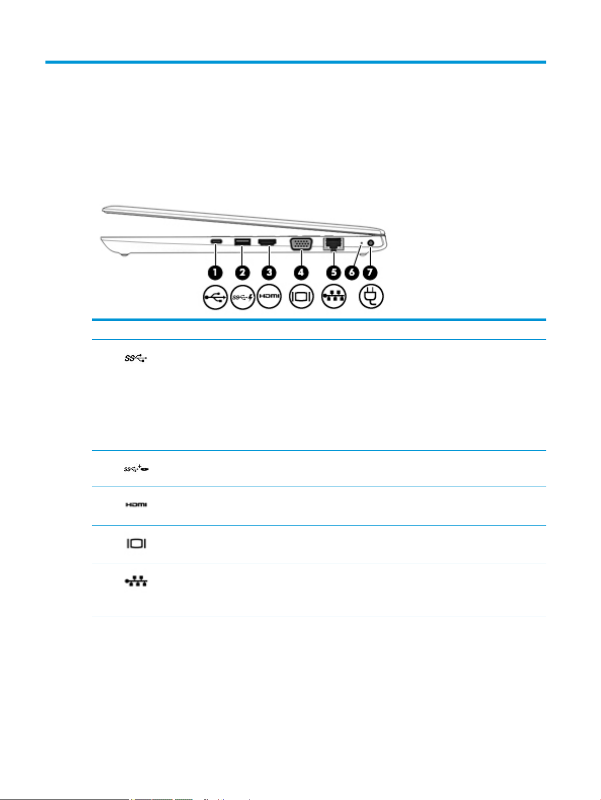
Right
Component Description
(1) USB Type-C power connector port Connects an AC adapter that has a USB Type-C connector, supplying
power to the computer and, if needed, charging the computer battery.
– and –
Connects a USB device that has a Type-C connector, such as a cell
phone, camera, activity tracker, or smartwatch, and provides highspeed data transfer.
NOTE: Cables and/or adapters (purchased separately) may be
required.
(2) USB 3.x SuperSpeed powered port Connects a USB device, such as a cell phone, camera, activity tracker,
optical drive, or smartwatch, and provides high-speed data transfer.
(3) HDMI port Connects an optional video or audio device, such as a high-denition
television, any compatible digital or audio component, or a high-speed
High Denition Multimedia Interface (HDMI) device.
(4) External monitor port Connects an external VGA monitor or projector.
(5) RJ-45 (network) jack/status lights Connects a network cable.
●
Green (right): The network is connected.
●
Amber (left): Activity is occurring on the network.
(6) Battery light When AC power is connected:
●
White: The battery charge is greater than 90 percent.
●
Amber: The battery charge is from 0 to 90 percent.
●
O: The battery is not charging.
When AC power is disconnected (battery not charging):
4 Chapter 2 Components
Page 15
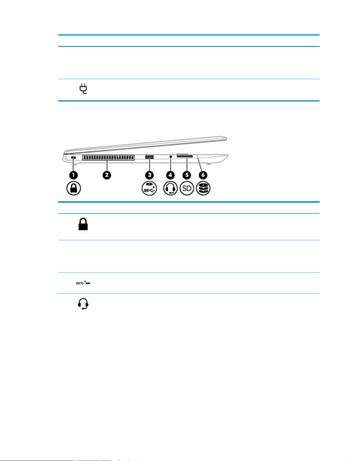
Left
Component Description
●
Blinking amber: The battery has reached a low battery level.
When the battery has reached a critical battery level, the battery
light begins blinking rapidly.
●
O: The battery is not charging.
(7) Power connector Connects an AC adapter.
Component Description
(1) Security cable slot Attaches an optional security cable to the computer.
NOTE: The security cable is designed to act as a deterrent, but it
may not prevent the computer from being mishandled or stolen.
(2) Vent Enables airow to cool internal components.
NOTE: The computer fan starts up automatically to cool internal
components and prevent overheating. It is normal for the internal fan
to cycle on and o during routine operation.
(3) USB 3.x SuperSpeed powered port Connects a USB device, such as a cell phone, camera, activity tracker,
optical drive, or smartwatch, and provides high-speed data transfer.
(4) Audio-out (headphone)/Audio-in
(microphone) combo jack
Connects optional powered stereo speakers, headphones, earbuds, a
headset, or a television audio cable. Also connects an optional
headset microphone. This jack does not support optional standalone
microphones.
WARNING! To reduce the risk of personal injury, adjust the volume
before putting on headphones, earbuds, or a headset. For additional
safety information, refer to the Regulatory, Safety, and
Environmental Notices.
To access this guide:
1. Type support in the taskbar search box, and then select the
HP Support Assistant app.
‒ or –
Click the question mark icon in the taskbar.
2. Select My PC, select the Specications tab, and then select User
Guides.
Left 5
Page 16
Component Description
NOTE: When a device is connected to the jack, the computer
speakers are disabled.
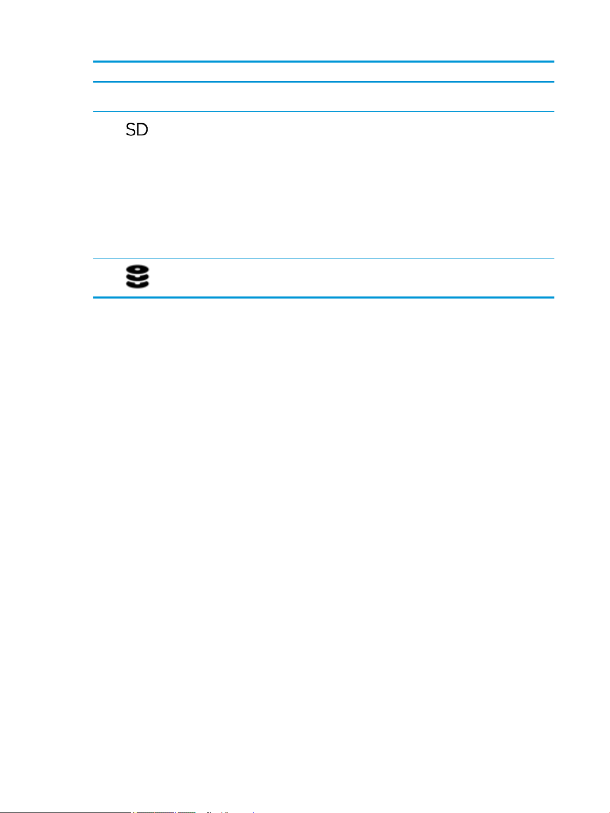
(5) Memory card reader Reads optional memory cards that store, manage, share, or access
information.
To insert a card:
1. Hold the card label-side up, with the connectors facing the
computer.
2. Insert the card into the memory card reader, and then press in
on the card until it is rmly seated.
To remove a card:
▲ Press in on the card, and then remove it from the memory card
reader.
(6) Drive light
●
Blinking white: The hard drive is being accessed.
●
Amber: HP 3D DriveGuard has temporarily parked the hard drive.
6 Chapter 2 Components
Page 17
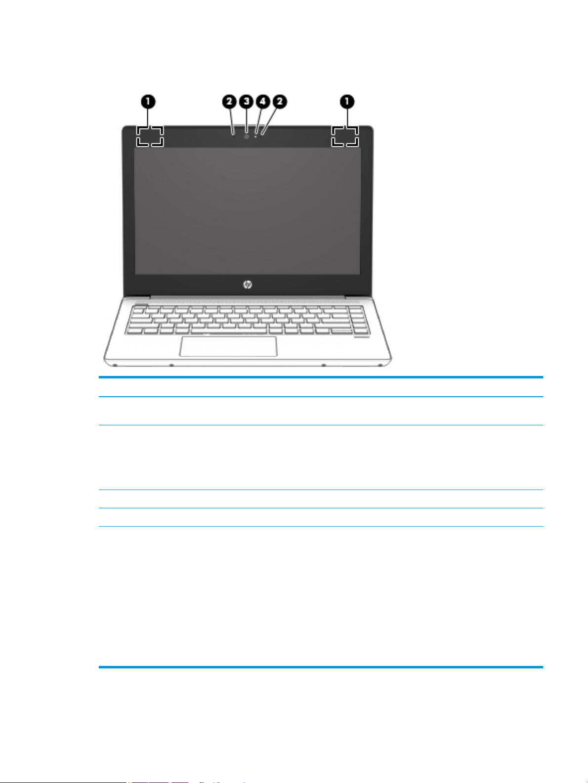
Display
Component Description
(1) WLAN antennas* Send and receive wireless signals to communicate with wireless local
area networks (WLANs).
(2) Camera Allow you to video chat, record video, and record still images. Some
(3) Internal microphones Record sound.
(4) Camera light On: One or more cameras are in use.
*The antennas are not visible from the outside of the computer. For optimal transmission, keep the areas immediately around the
antennas free from obstructions.
For wireless regulatory notices, see the section of the Regulatory, Safety, and Environmental Notices that applies to your country or
region.
To access this guide:
1. Type support in the taskbar search box, and then select the HP Support Assistant app.
‒ or –
Click the question mark icon in the taskbar.
2. Select My PC, select the Specications tab, and then select User Guides.
cameras also allow a facial recognition logon to Windows, instead of a
password logon.
NOTE: Camera functions vary depending on the camera hardware
and software installed on your product.
Display 7
Page 18
Keyboard area
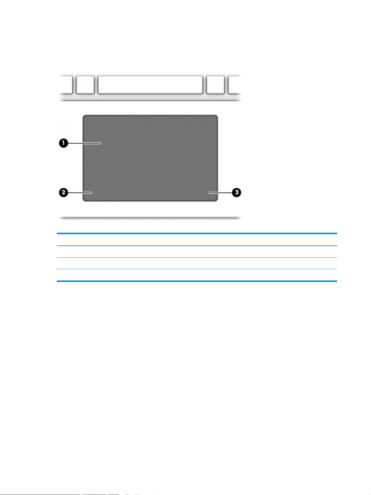
TouchPad
Component Description
(1) TouchPad zone Reads your nger gestures to move the pointer or activate items on the screen.
(2) Left TouchPad button Functions like the left button on an external mouse.
(3) Right TouchPad button Functions like the right button on an external mouse.
8 Chapter 2 Components
Page 19
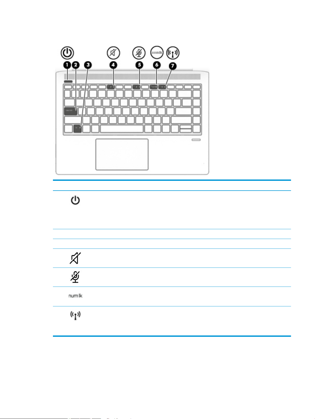
Lights
Component Description
(1) Power light
(2) Caps lock light On: Caps lock is on, which switches the key input to all capital letters.
(3) Fn lock light On: The fn key is locked.
(4) Mute light
(5) Microphone mute light
(6) Num lk light On: Num lock is on.
(7) Wireless light On: An integrated wireless device, such as a wireless local area network (WLAN)
●
On: The computer is on.
●
Blinking: The computer is in the Sleep state, a power-saving state. The
computer shuts o power to the display and other unneeded components.
●
O: The computer is o or in Hibernation. Hibernation is a power-saving state
that uses the least amount of power.
●
Amber: Computer sound is o.
●
O: Computer sound is on.
●
Amber: Microphone is o.
●
O: Microphone is on.
device and/or a Bluetooth® device, is on.
NOTE: On some models, the wireless light is amber when all wireless devices are
o.
Keyboard area 9
Page 20
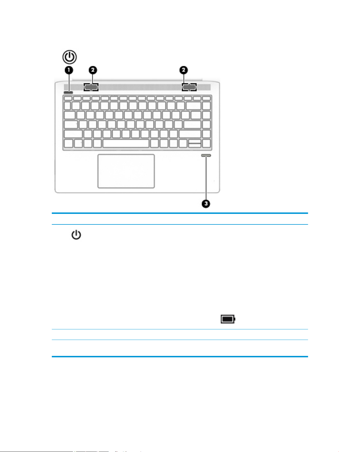
Buttons, speakers, and ngerprint reader
Component Description
(1) Power button
(2) Speakers (2) Produce sound.
(3) Fingerprint reader (select
products only)
●
When the computer is o, press the button to turn on the computer.
●
When the computer is on, press the button briey to initiate Sleep.
●
When the computer is in the Sleep state, press the button briey to exit Sleep.
●
When the computer is in Hibernation, press the button briey to exit
Hibernation.
CAUTION: Pressing and holding down the power button results in the loss of
unsaved information.
If the computer has stopped responding and shutdown procedures are ineective,
press and hold the power button for at least 5 seconds to turn o the computer.
To learn more about your power settings, see your power options.
▲
Right-click the Power meter icon and then select Power Options.
Allows a ngerprint logon to Windows, instead of a password logon.
10 Chapter 2 Components
Page 21
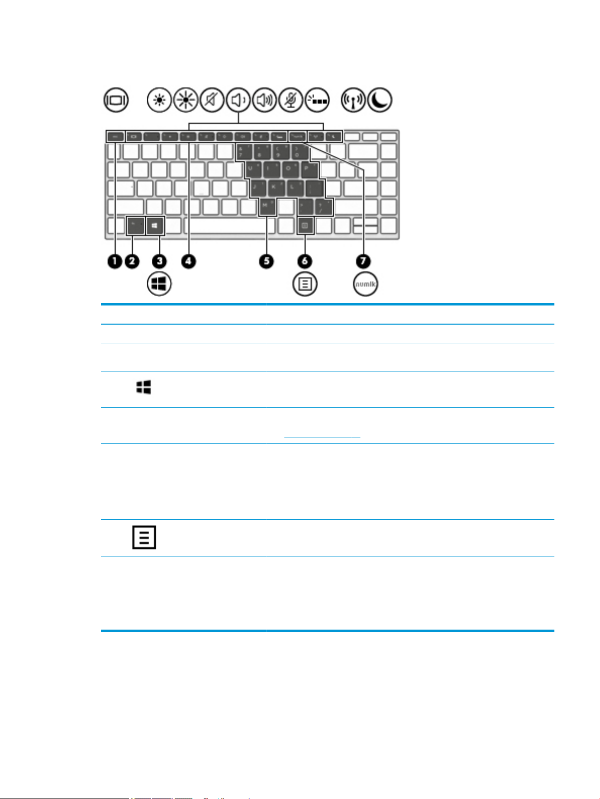
Special keys
Component Description
(1) esc key Displays system information when pressed in combination with the fn key.
(2) fn key Executes frequently used system functions when pressed in combination with
another key. Such key combinations are called hot keys.
(3) Windows key Opens the Start menu.
NOTE: Pressing the Windows key again will close the Start menu.
(4) Action keys Execute frequently used system functions.
See Action keys on page 12.
(5) Embedded numeric keypad A numeric keypad superimposed over the keyboard alphabet keys. When fn+num lk
is pressed, the keypad can be used like an external numeric keypad. Each key on the
keypad performs the function indicated by the icon in the upper-right corner of the
key.
NOTE: If the keypad function is active when the computer is turned o, that
function is reinstated when the computer is turned back on.
(6) Windows application key Displays options for a selected object.
(7) num lk key Turns the embedded numeric keypad on and o when pressed in combination with
the fn key.
– or –
Alternates between the navigational and numeric functions on the integrated
numeric keypad.
Keyboard area 11
Page 22
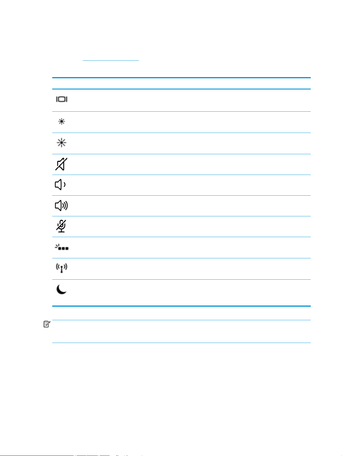
Action keys
An action key performs the function indicated by the icon on the key. To determine which keys are on your
product, see Special keys on page 11.
▲
Icon Description
To use an action key, press and hold the key.
Switches the screen image among display devices connected to the system. For example, if a monitor is
connected to the computer, repeatedly pressing the key alternates the screen image from computer display
to monitor display to simultaneous display on both the computer and monitor.
Decreases the screen brightness incrementally as long as you hold down the key.
Increases the screen brightness incrementally as long as you hold down the key.
Mutes or restores speaker sound.
Decreases speaker volume incrementally while you hold down the key.
Increases speaker volume incrementally while you hold down the key.
Mutes the microphone.
Turns the keyboard backlight o or on.
NOTE: To conserve battery power, turn o this feature.
Turns the wireless feature on or o.
NOTE: A wireless network must be set up before a wireless connection is possible.
Initiates Sleep, which saves your information in system memory. The display and other system components
turn o and power is conserved. To exit Sleep, briey press the power button.
CAUTION: To reduce the risk of information loss, save your work before initiating Sleep.
NOTE: The action key feature is enabled at the factory. You can disable this feature by pressing and holding
the fn key and the left shift key. The fn lock light will turn on. After you have disabled the action key feature,
you can still perform each function by pressing the fn key in combination with the appropriate action key.
12 Chapter 2 Components
Page 23
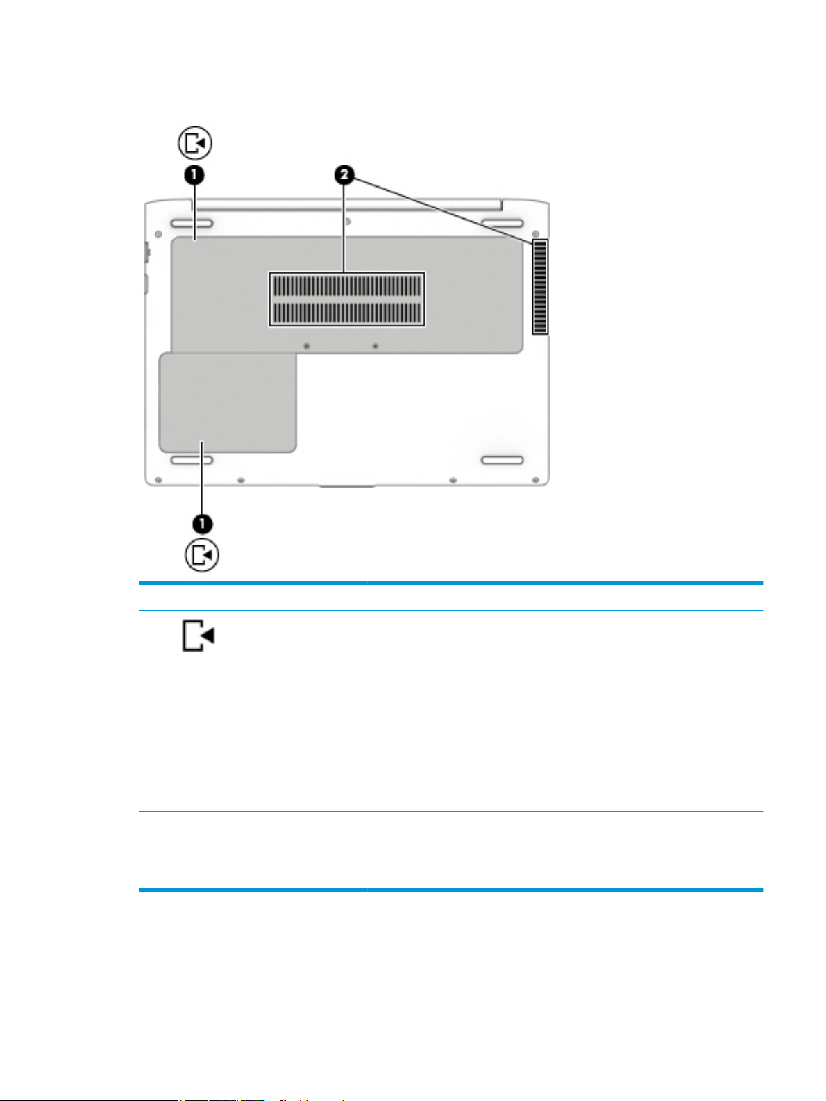
Bottom
Component Description
(1) Service doors (2) Provide access to the hard drive bay, the WLAN module slot and the memory module
slots.
CAUTION: To prevent an unresponsive system, replace the wireless module only
with a wireless module authorized for use in the computer by the governmental
agency that regulates wireless devices in your country or region. If you replace the
module and then receive a warning message, remove the module to restore
computer functionality, and then contact support.
▲ Type support in the taskbar search box, and then select the HP Support
Assistant app.
– or –
Click the question mark icon in the taskbar.
(2) Vents Enable airow to cool internal components.
NOTE: The computer fan starts up automatically to cool internal components and
prevent overheating. It is normal for the internal fan to cycle on and o during
routine operation.
Bottom 13
Page 24
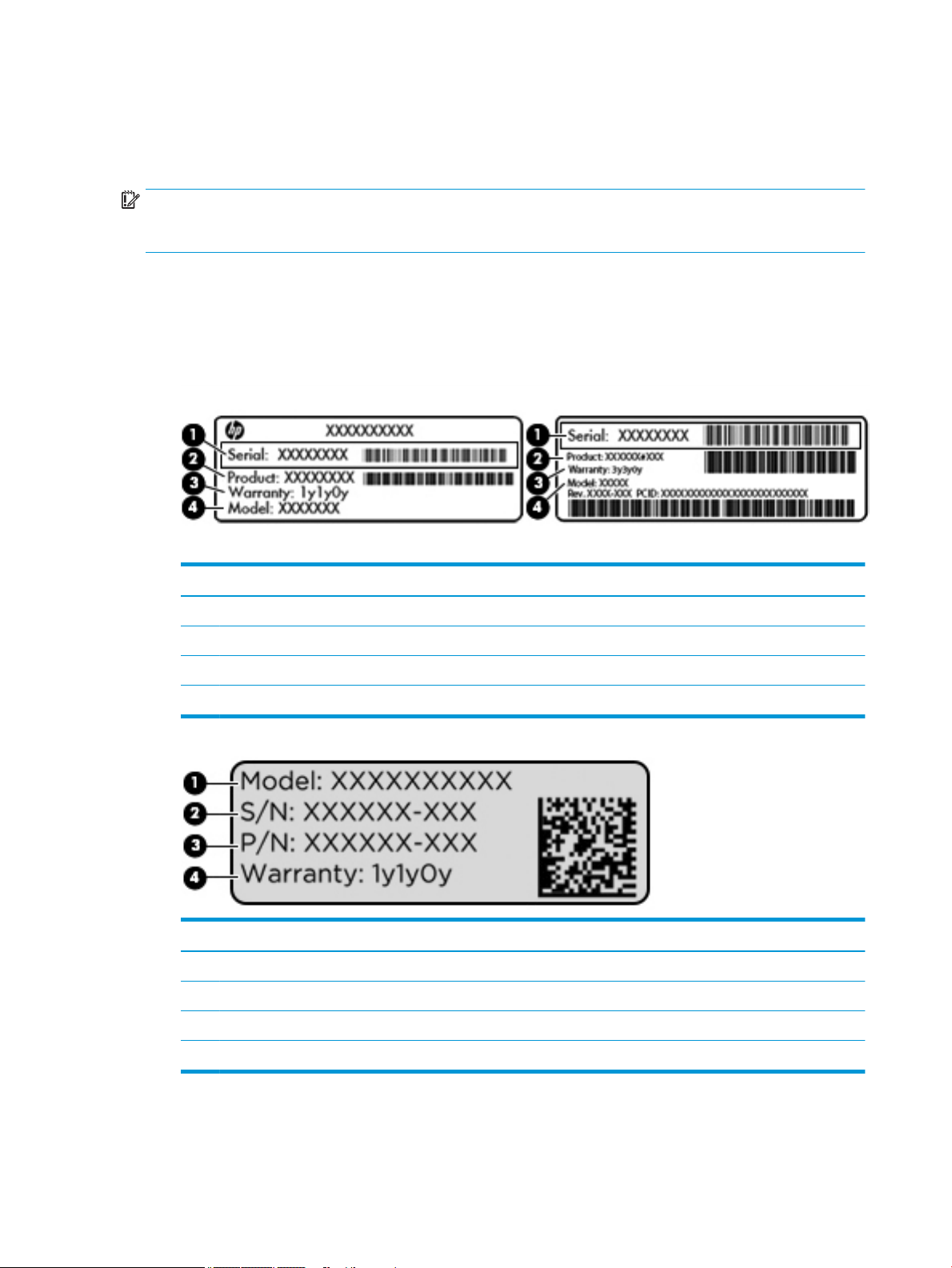
Labels
The labels axed to the computer provide information you may need when you troubleshoot system
problems or travel internationally with the computer.
IMPORTANT: Check the following locations for the labels described in this section: the bottom of the
computer, the bottom of a tablet kickstand, inside the battery bay, under the service door, or on the back of
the display.
●
Service label—Provides important information to identify your computer. When contacting support, you
will probably be asked for the serial number, and possibly for the product number or the model number.
Locate these numbers before you contact support.
Your service label will resemble one of the examples shown below. Refer to the illustration that most
closely matches the service label on your computer.
Component
(1) Serial number
(2) Product number
(3) Warranty period
(4) Model number (select products only)
Component
(1) Model name (select products only)
(2) Serial number
(3) Product number
(4) Warranty period
●
Regulatory label(s)—Provide(s) regulatory information about the computer.
●
Wireless certication label(s)—Provide(s) information about optional wireless devices and the approval
markings for the countries or regions in which the devices have been approved for use.
14 Chapter 2 Components
Page 25
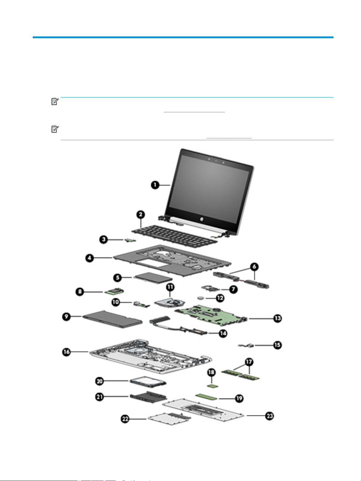
3 Illustrated parts catalog
Computer major components
NOTE: HP continually improves and changes product parts. For complete and current information on
supported parts for your computer, go to http://partsurfer.hp.com, select your country or region, and then
follow the on-screen instructions.
NOTE: Details about your computer, including model, serial number, product key, and length of warranty,
are on the service tag at the bottom of your computer. See Labels on page 14 for details.
Computer major components 15
Page 26

Item Description Spare part number
(1) Display panel assembly, touch screen
NOTE: Non-touch displays are spared only at the subcomponent level.
(2) Keyboard (includes cables)
No backlight L04645-xxx
Backlit L04644-xxx
(3) Power button board L02276-001
(4) Top cover L02278-001
(5) TouchPad L02279-001
(6) Speaker assembly L01087-001
(7) Fingerprint reader assembly (includes cable) L01091-001
(8) Card reader board L02277-001
(9) Battery, Li-ion (4-cell, 48 WHr, 4.21 Ah) 851610-855
(10) USB board L02275-001
(11) Fan L01088-001
(12) RTC battery not spared
(13) System board (includes replacement thermal material)
All system boards use the following part numbers:
xxxxxx-001: Non-Windows operating system
xxxxxx-601: Windows 10 operating system
●
Intel Core i7-8550U processor L02274-xxx
●
Intel Core i5-8250U processor L02273-xxx
●
Intel Core i7-7500U processor L02272-xxx
●
Intel Core i5-7200U processor L02271-xxx
(14) Heat sink assembly (includes replacement thermal material) L01086-001
(15) Power connector cable L07857-001
(16) Base enclosure L02280-001
(17) Memory modules (DDR4-2133)
8-GB 820570-001
4-GB 820569-001
(18) WLAN module
Intel Dual Band Wireless-AC 3168 802.11ac, 1×1 Wi-Fi + Bluetooth 4.0 combination adapter 852511-001
Intel Dual Band Wireless-AC 8265, 802.11ac, 2×2 Wi-Fi + Bluetooth 4.2 combination adapter 851594-001
(19) M.2 solid-state drive
512-GB, Turbo Drive L02285-001
16 Chapter 3 Illustrated parts catalog
Page 27
Item Description Spare part number
256-GB, PCIe L02284-001
128-GB, SATA-3 L02283-001
(20) Hard drive
1 TB, 5400 rpm, 7 mm 762990-001
500 GB, 7200 rpm, 7 mm 703267-001
(21) Hard drive cover
(22) Drive service door
(23) Main service door
Cable Kit
L01083-001
NOTE: The hard drive cover is included in the Hard Drive Hardware Kit.
L01083-001
NOTE: The drive service door is included in the Hard Drive Hardware Kit.
L01084-001
NOTE: The main service door is included in the Plastics Kit.
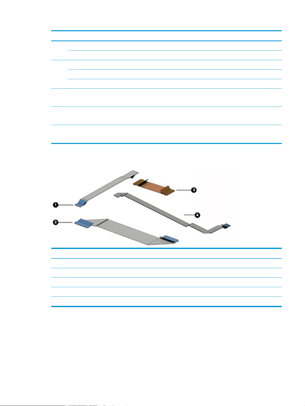
Item Description Spare part number
Cable Kit L01082-001
(1) Power button board cable
(2) Card reader board cable
(3) USB board cable
(4) TouchPad cable
Cable Kit 17
Page 28
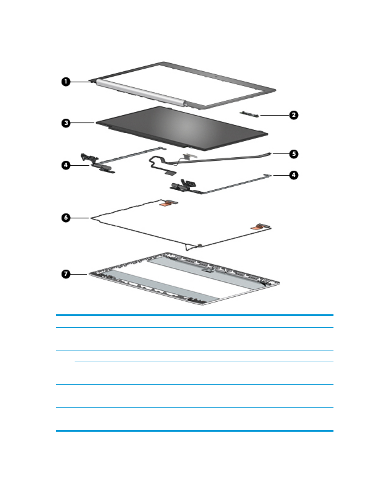
Display components
Item Description Spare part number
(1) Display bezel L02281-001
(2) Camera module L01065-001
(3) Display panel (raw)
FHD L02286-001
HD L02287-001
(4) Hinge Kit (includes left and right hinges) L01097-001
(5) Display/camera cable assembly L01095-001
(6) WLAN antennas L01949-001
(7) Display rear cover (includes wireless antennas) L01092-001
18 Chapter 3 Illustrated parts catalog
Page 29
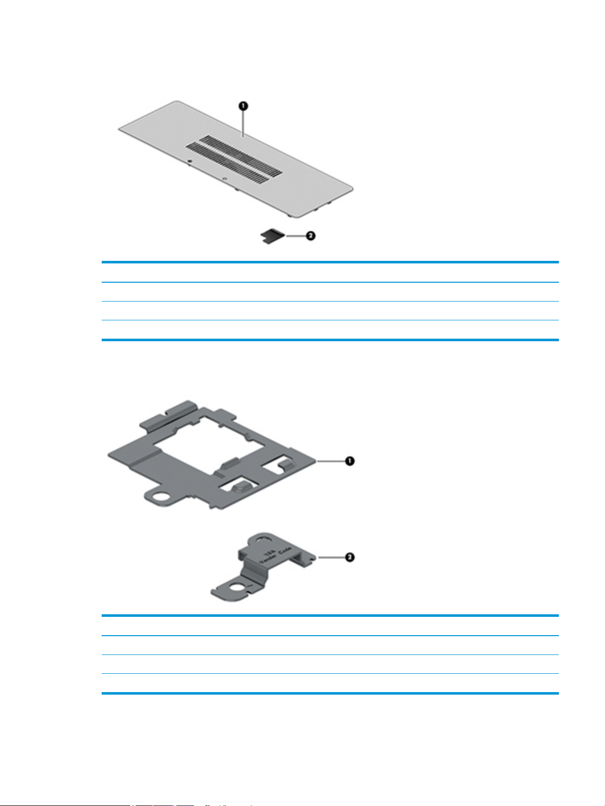
Plastics Kit
Item Description Spare part number
Plastics Kit L01084-001
(1) Main service door
(2) Fingerprint reader insert (for use in models without a ngerprint reader)
Bracket Kit
Item Description Spare part number
Bracket Kit L01051-001
(1) Fingerprint reader bracket
(2) USB reader bracket
Plastics Kit 19
Page 30
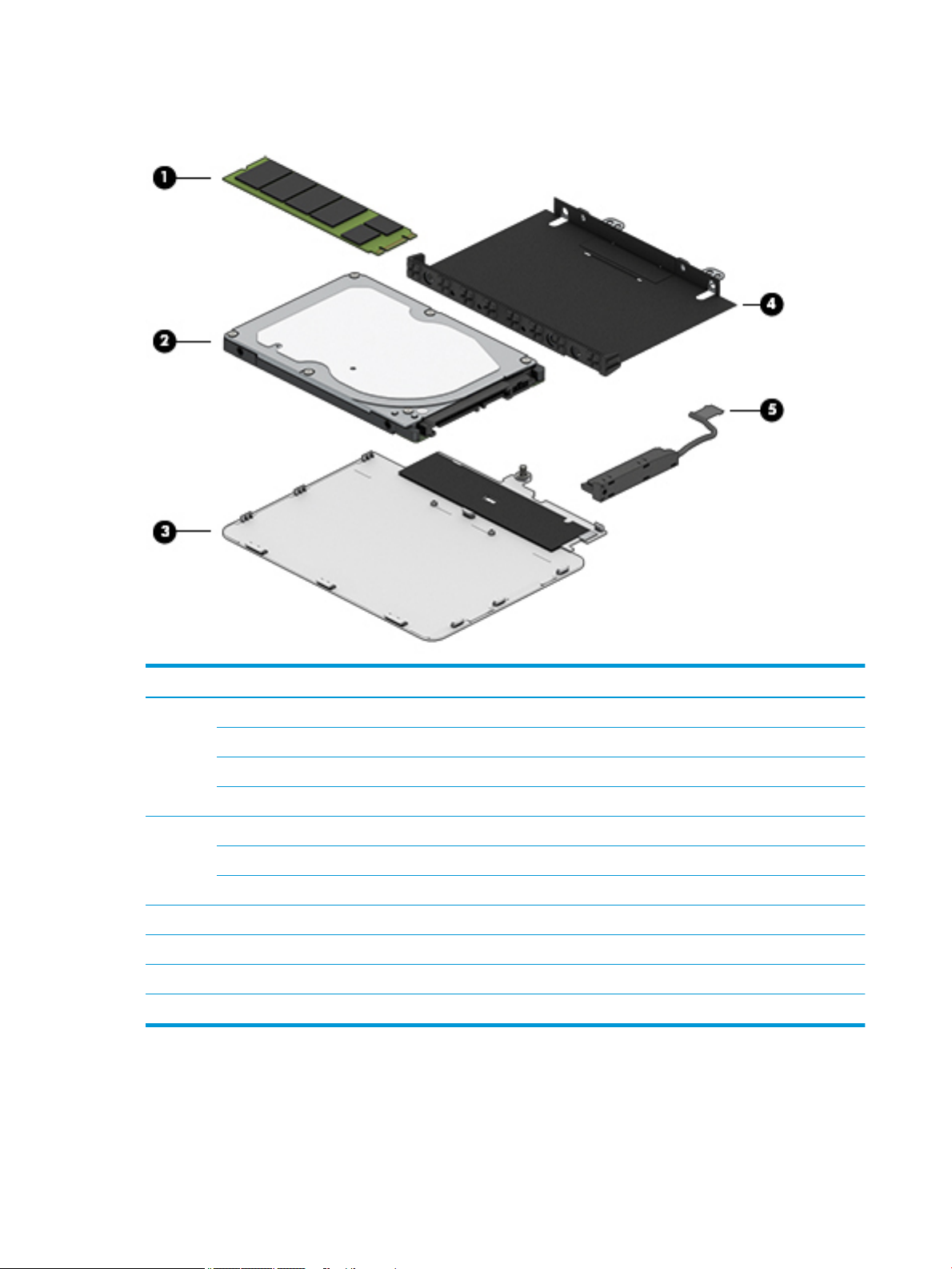
Mass storage devices
Item Description Spare part number
(1) Solid-state drive, M.2
512-GB, Turbo Drive L02285-001
256-GB, PCIe L02284-001
128-GB, SATA-3 L02283-001
(2) Hard drive
1 TB, 5400 rpm, 7 mm 762990-001
500 GB, 7200 rpm, 7 mm 703267-001
Hard Drive Hardware Kit, includes: L01083-001
(3) Drive service door
(4) Hard drive cover
(5) Hard drive cable
20 Chapter 3 Illustrated parts catalog
Page 31

Miscellaneous parts
Description Spare part number
Smart, AC adapter, 65 W, 4.5 mm barrel connector 913691-850
Power cord (3-pin, C5, black, 1.0-m) 931251-001
Screw Kit L01098-001
Mouse
HP USB Laser Mouse 674318-001
HP Comfort Grip Wireless Mouse 691922-001
HP USB Travel Mouse 757770-001
Cases
Top load case 679921-001
Messenger bag 679922-001
Backpack 679923-001
HP keyed cable lock 840158-001
HP Smart AC Adapter dongle, 7.4 mm 734734-001
HP USB Travel Dock 844551-001
Miscellaneous parts 21
Page 32

4 Removal and replacement procedures
preliminary requirements
Tools required
You will need the following tools to complete the removal and replacement procedures:
●
Flat-bladed screwdriver
●
Phillips P0 and P1 screwdrivers
●
Torx T8 screwdriver
Service considerations
The following sections include some of the considerations that you must keep in mind during disassembly
and assembly procedures.
NOTE: As you remove each subassembly from the computer, place the subassembly (and all accompanying
screws) away from the work area to prevent damage.
Plastic parts
CAUTION: Using excessive force during disassembly and reassembly can damage plastic parts. Use care
when handling the plastic parts. Apply pressure only at the points designated in the maintenance
instructions.
22 Chapter 4 Removal and replacement procedures preliminary requirements
Page 33

Cables and connectors
CAUTION: When servicing the computer, be sure that cables are placed in their proper locations during the
reassembly process. Improper cable placement can damage the computer.
Cables must be handled with extreme care to avoid damage. Apply only the tension required to unseat or seat
the cables during removal and insertion. Handle cables by the connector whenever possible. In all cases, avoid
bending, twisting, or tearing cables. Be sure that cables are routed in such a way that they cannot be caught
or snagged by parts being removed or replaced. Handle ex cables with extreme care; these cables
tear easily.
Drive handling
CAUTION: Drives are fragile components that must be handled with care. To prevent damage to the
computer, damage to a drive, or loss of information, observe these precautions:
Before removing or inserting a hard drive, shut down the computer. If you are unsure whether the computer is
o or in Hibernation, turn the computer on, and then shut it down through the operating system.
Before handling a drive, be sure that you are discharged of static electricity. While handling a drive, avoid
touching the connector.
Before removing a diskette drive or optical drive, be sure that a diskette or disc is not in the drive and be sure
that the optical drive tray is closed.
Handle drives on surfaces covered with at least one inch of shock-proof foam.
Avoid dropping drives from any height onto any surface.
After removing a hard drive, an optical drive, or a diskette drive, place it in a static-proof bag.
Avoid exposing a hard drive to products that have magnetic elds, such as monitors or speakers.
Avoid exposing a drive to temperature extremes or liquids.
If a drive must be mailed, place the drive in a bubble pack mailer or other suitable form of protective
packaging and label the package “FRAGILE.”
Service considerations 23
Page 34

Grounding guidelines
Electrostatic discharge damage
Electronic components are sensitive to electrostatic discharge (ESD). Circuitry design and structure determine
the degree of sensitivity. Networks built into many integrated circuits provide some protection, but in many
cases, ESD contains enough power to alter device parameters or melt silicon junctions.
A discharge of static electricity from a nger or other conductor can destroy static-sensitive devices or
microcircuitry. Even if the spark is neither felt nor heard, damage may have occurred.
An electronic device exposed to ESD may not be aected at all and can work perfectly throughout a normal
cycle. Or the device may function normally for a while, and then degrade in the internal layers, reducing its life
expectancy.
CAUTION: To prevent damage to the computer when you are removing or installing internal components,
observe these precautions:
Keep components in their electrostatic-safe containers until you are ready to install them.
Use nonmagnetic tools.
Before touching an electronic component, discharge static electricity by using the guidelines described in this
section.
Avoid touching pins, leads, and circuitry. Handle electronic components as little as possible.
If you remove a component, place it in an electrostatic-safe container.
The following table shows how humidity aects the electrostatic voltage levels generated by dierent
activities.
CAUTION: A product can be degraded by as little as 700 V.
Typical electrostatic voltage levels
Relative humidity
Event 10% 40% 55%
Walking across carpet 35,000 V 15,000 V 7,500 V
Walking across vinyl oor 12,000 V 5,000 V 3,000 V
Motions of bench worker 6,000 V 800 V 400 V
Removing DIPS from plastic tube 2,000 V 700 V 400 V
Removing DIPS from vinyl tray 11,500 V 4,000 V 2,000 V
Removing DIPS from Styrofoam 14,500 V 5,000 V 3,500 V
Removing bubble pack from PCB 26,500 V 20,000 V 7,000 V
Packing PCBs in foam-lined box 21,000 V 11,000 V 5,000 V
24 Chapter 4 Removal and replacement procedures preliminary requirements
Page 35

Packaging and transporting guidelines
Follow these grounding guidelines when packaging and transporting equipment:
●
To avoid hand contact, transport products in static-safe tubes, bags, or boxes.
●
Protect ESD-sensitive parts and assemblies with conductive or approved containers or packaging.
●
Keep ESD-sensitive parts in their containers until the parts arrive at static-free workstations.
●
Place items on a grounded surface before removing items from their containers.
●
Always be properly grounded when touching a component or assembly.
●
Store reusable ESD-sensitive parts from assemblies in protective packaging or nonconductive foam.
●
Use transporters and conveyors made of antistatic belts and roller bushings. Be sure that mechanized
equipment used for moving materials is wired to ground and that proper materials are selected to avoid
static charging. When grounding is not possible, use an ionizer to dissipate electric charges.
Workstation guidelines
Follow these grounding workstation guidelines:
●
Cover the workstation with approved static-shielding material.
●
Use a wrist strap connected to a properly grounded work surface and use properly grounded tools and
equipment.
●
Use conductive eld service tools, such as cutters, screwdrivers, and vacuums.
●
When xtures must directly contact dissipative surfaces, use xtures made only of static-safe materials.
●
Keep the work area free of nonconductive materials, such as ordinary plastic assembly aids and
Styrofoam.
●
Handle ESD-sensitive components, parts, and assemblies by the case or PCM laminate. Handle these
items only at static-free workstations.
●
Avoid contact with pins, leads, or circuitry.
●
Turn o power and input signals before inserting or removing connectors or test equipment.
Service considerations 25
Page 36

Equipment guidelines
Grounding equipment must include either a wrist strap or a foot strap at a grounded workstation.
●
When seated, wear a wrist strap connected to a grounded system. Wrist straps are exible straps with a
minimum of one megohm ±10% resistance in the ground cords. To provide proper ground, wear a strap
snugly against the skin at all times. On grounded mats with banana-plug connectors, use alligator clips
to connect a wrist strap.
●
When standing, use foot straps and a grounded oor mat. Foot straps (heel, toe, or boot straps) can be
used at standing workstations and are compatible with most types of shoes or boots. On conductive
oors or dissipative oor mats, use foot straps on both feet with a minimum of one megohm resistance
between the operator and ground. To be
the skin.
The following grounding equipment is recommended to prevent electrostatic damage:
●
Antistatic tapes
●
Antistatic smocks, aprons, and sleeve protectors
●
Conductive bins and other assembly or soldering aids
●
Nonconductive foam
●
Conductive tabletop workstations with ground cords of one megohm resistance
●
Static-dissipative tables or oor mats with hard ties to the ground
eective, the conductive strips must be worn in contact with
●
Field service kits
●
Static awareness labels
●
Material-handling packages
●
Nonconductive plastic bags, tubes, or boxes
●
Metal tote boxes
●
Electrostatic voltage levels and protective materials
The following table lists the shielding protection provided by antistatic bags and oor mats.
Material Use Voltage protection level
Antistatic plastic Bags 1,500 V
Carbon-loaded plastic Floor mats 7,500 V
Metallized laminate Floor mats 5,000 V
26 Chapter 4 Removal and replacement procedures preliminary requirements
Page 37

5 Removal and replacement procedures for
Customer Self-Repair parts
CAUTION: The Customer Self-Repair program is not available in all locations. Installing a part not supported
by the Customer Self-Repair program may void your warranty. Check your warranty to determine if Customer
Self-Repair is supported in your location.
NOTE: HP continually improves and changes product parts. For complete and current information on
supported parts for your computer, go to http://partsurfer.hp.com, select your country or region, and then
follow the on-screen instructions.
Component replacement procedures
NOTE: Please read and follow the procedures described here to access and replace Customer Self-Repair
parts successfully.
NOTE: Details about your computer, including model, serial number, product key, and length of warranty,
are on the service tag at the bottom of your computer. See Labels on page 14 for details.
This chapter provides removal and replacement procedures for Customer Self-Repair parts.
There are as many as 12 screws that must be removed, replaced, or loosened when servicing Customer SelfRepair parts. Make special note of each screw size and location during removal and replacement.
Battery Safe mode
Before removing internal components, you must place the computer in “Battery Safe mode.” This mode
avoids short-circuits or system malfunction by removing power from internal components.
To place the computer in “Battery Safe mode,” follow these steps:
1. With the computer turned o and AC adapter connected, press the following key and button
combination: Windows key + Backspace key + Power button.
2. Turn the computer on to initiate “Battery Safe mode.”
3. After the computer powers o, disconnect the AC adapter.
In “Battery Safe mode,” the power button will not turn the computer on if the AC adapter is not connected.
To disengage “Battery Safe mode,” plug in the AC adapter and press the power button.
Component replacement procedures 27
Page 38

Service doors
Description Spare part number
Main service door (included in Plastics Kit) L01084-001
Drive service door (included in Hard Drive Hardware Kit) L01083-001
The bottom of the computer has two service doors. The drive service door only provides access to the hard
drive. The main service door provides access to the memory modules, wireless module, M.2 solid-state drive,
and keyboard screws.
Before removing the service doors, follow these steps:
1. Shut down the computer. If you are unsure whether the computer is o or in Hibernation, turn the
computer on, and then shut it down through the operating system.
2. Place the computer in “Battery Safe mode” (Battery Safe mode on page 27).
3. Disconnect all external devices connected to the computer.
4. Disconnect the power from the computer by rst unplugging the power cord from the AC outlet, and
then unplugging the AC adapter from the computer.
Remove the service doors:
Main service door
1. Loosen the captive Phillips screw (1).
2. Lift the bottom of the door upward (2), and then remove the door from the computer (3).
Drive service door
3. Loosen the captive Phillips screw (1).
28 Chapter 5 Removal and replacement procedures for Customer Self-Repair parts
Page 39

4. Lift the bottom of the door upward (2), and then remove the door from the computer (3).
Reverse these procedures to install the service doors.
Component replacement procedures 29
Page 40

Memory modules
Description Spare part number
8-GB (DDR4-2133) 820570-001
4-GB (DDR4-2133) 820569-001
Update BIOS before adding memory modules
Before adding new memory, make sure you update the computer to the latest BIOS.
CAUTION: Failure to update the computer to the latest BIOS prior to installing new memory may result in
various system problems.
To update BIOS:
1. Navigate to www.hp.com.
2. Move the cursor over Support to display the pull-down menu, and then click Software & drivers.
3. Type your product name, number, or serial number, and then click Find.
4. Click BIOS, and then click Download.
5. Follow the on-screen instructions.
Before removing the memory module, follow these steps:
1. Shut down the computer. If you are unsure whether the computer is o or in Hibernation, turn the
computer on, and then shut it down through the operating system.
2. Place the computer in “Battery Safe mode” (Battery Safe mode on page 27).
3. Disconnect all external devices connected to the computer.
4. Disconnect the power from the computer by rst unplugging the power cord from the AC outlet, and
then unplugging the AC adapter from the computer.
5. Remove the main service door (Service doors on page 28).
Remove the memory module:
1. Spread the retaining tabs (1) on each side of the memory module slot to release the memory module.
(The edge of the module opposite the slot rises away from the computer.)
30 Chapter 5 Removal and replacement procedures for Customer Self-Repair parts
Page 41

2. Remove the memory module (2) by pulling the module away from the slot at an angle.
NOTE: Memory modules are designed with a notch to prevent incorrect insertion into the memory
module slot.
Reverse this procedure to install a memory module.
Component replacement procedures 31
Page 42

WLAN/Bluetooth combo card
The computer uses a card that provides both WLAN and Bluetooth functionality.
Description Spare part number
Intel Dual Band Wireless-AC 3168 802.11ac, 1×1 Wi-Fi + Bluetooth 4.0 combination adapter 852511-001
Intel Dual Band Wireless-AC 8265, 802.11ac, 2×2 Wi-Fi + Bluetooth 4.2 combination adapter 851594-001
Before removing the WLAN module, follow these steps:
1. Shut down the computer. If you are unsure whether the computer is o or in Hibernation, turn the
computer on, and then shut it down through the operating system.
2. Place the computer in “Battery Safe mode” (Battery Safe mode on page 27).
3. Disconnect all external devices connected to the computer.
4. Disconnect the power from the computer by rst unplugging the power cord from the AC outlet, and
then unplugging the AC adapter from the computer.
5. Remove the main service door (Service doors on page 28).
Remove the WLAN module:
1. Disconnect the WLAN antenna cables (1) from the terminals on the WLAN module.
NOTE: The WLAN antenna cable labeled “1” connects to the WLAN module “Main” terminal labeled “1”.
The WLAN antenna cable labeled “2” connects to the WLAN module “Aux” terminal labeled “2”. If the
computer is equipped with an 802.11a/b/g/n WLAN module, the yellow WLAN antenna cable connects to
the middle terminal on the WLAN module.
2. Remove the Phillips M2.0×4.0 screw (2) that secures the WLAN module to the computer. (The edge of
the module opposite the slot rises away from the computer.)
32 Chapter 5 Removal and replacement procedures for Customer Self-Repair parts
Page 43

3. Remove the WLAN module (3) by pulling the module away from the slot at an angle.
NOTE: WLAN modules are designed with a notch to prevent incorrect insertion.
NOTE: If the WLAN antennas are not connected to the terminals on the WLAN module, the protective
sleeves must be installed on the antenna connectors, as shown in the following illustration.
Reverse this procedure to install the WLAN module.
Component replacement procedures 33
Page 44

Hard drive
Description Spare part number
Hard drives
1 TB, 5400 rpm, 7 mm 762990-001
500 GB, 7200 rpm, 7 mm 703267-001
Hard drive cover (Included in the Hard Drive Hardware Kit) L01083-001
Before removing the hard drive, follow these steps:
1. Shut down the computer. If you are unsure whether the computer is o or in Hibernation, turn the
2. Place the computer in “Battery Safe mode” (Battery Safe mode on page 27).
3. Disconnect all external devices connected to the computer.
4. Disconnect the power from the computer by rst unplugging the power cord from the AC outlet, and
5. Remove the main service door (Service doors on page 28).
6. Remove the drive service door (Service doors on page 28).
computer on, and then shut it down through the operating system.
then unplugging the AC adapter from the computer.
Remove the hard drive:
1. Remove the 2 Phillips M2.0×3.0 screws (1) that secure the hard drive to the computer.
2. Lift the bracket side of the hard drive upward (2), and then use the tab to pull and lift the drive up
enough to access the cable (3).
3. Disconnect the cable from the drive (4).
34 Chapter 5 Removal and replacement procedures for Customer Self-Repair parts
Page 45

4. Remove the hard drive from the bay (5).
5. To remove the hard drive cover from the hard drive, remove the 4 Phillips M3.0×3.0 screws (1) that
secure the bracket to the drive, and then lift the cover o the drive (2).
Reverse these procedures to install a hard drive.
Component replacement procedures 35
Page 46

M.2 solid-state drive
Description Spare part number
512-GB, Turbo Drive L02285-001
256-GB, PCIe L02284-001
128-GB, SATA-3 L02283-001
Before removing the solid-state drive, follow these steps:
1. Shut down the computer. If you are unsure whether the computer is o or in Hibernation, turn the
computer on, and then shut it down through the operating system.
2. Place the computer in “Battery Safe mode” (Battery Safe mode on page 27).
3. Disconnect all external devices connected to the computer.
4. Disconnect the power from the computer by rst unplugging the power cord from the AC outlet, and
then unplugging the AC adapter from the computer.
5. Remove the main service door (Service doors on page 28).
6. Remove the drive service door (Service doors on page 28).
Remove the solid-state drive:
1. Remove the Phillips M2.0×4.0 screw (1) that secures the solid-state drive to the computer. (The edge of
the module opposite the slot rises away from the computer.)
2. Remove the solid-state drive (2) by pulling the module away from the slot at an angle.
Reverse this procedure to install the solid-state drive.
36 Chapter 5 Removal and replacement procedures for Customer Self-Repair parts
Page 47

Keyboard
In this section, the rst table provides the main spare part number for the keyboards. The second table
provides the country codes.
Before removing the keyboard, follow these steps:
1. Shut down the computer. If you are unsure whether the computer is o or in Hibernation, turn the
2. Place the computer in “Battery Safe mode” (Battery Safe mode on page 27).
3. Disconnect all external devices connected to the computer.
4. Disconnect the power from the computer by rst unplugging the power cord from the AC outlet, and
5. Remove the main service door (Service doors on page 28).
Remove the keyboard:
Description Spare part number
Keyboard, no backlight L04645-001
Keyboard, backlit L04644-001
computer on, and then shut it down through the operating system.
then unplugging the AC adapter from the computer.
1. Remove the 2 Phillips M2.5×5.0 screws that secure the keyboard to the computer (1).
2. Insert a tool into the access hole next to the fan in the bottom of the computer and push to disengage
the keyboard from the top cover (2).
Component replacement procedures 37
Page 48

3. Lift the top of the keyboard upward, and then rotate the keyboard until it rests on the palm rest.
NOTE: A cable (or cables) connect the bottom of the keyboard to the system board. Make sure not to
prematurely pull the cables out of the system board connector(s).
4. If applicable, disconnect the backlight cable by lifting the ZIF connector latch (1), and then disconnect
the cable from the system board (2).
5. Disconnect the keyboard cable by lifting the reverse ZIF connector latch (3), and then disconnect the
keyboard cable from the system board (4).
38 Chapter 5 Removal and replacement procedures for Customer Self-Repair parts
Page 49

6. Remove the keyboard (5).
Reverse this procedure to install the keyboard.
Component replacement procedures 39
Page 50

6 Removal and replacement procedures for
Authorized Service Provider parts
CAUTION: Components described in this chapter should only be accessed by an authorized service provider.
Accessing these parts can damage the computer or void the warranty.
NOTE: HP continually improves and changes product parts. For complete and current information on
supported parts for your computer, go to http://partsurfer.hp.com, select your country or region, and then
follow the on-screen instructions.
Component replacement procedures
NOTE: Details about your computer, including model, serial number, product key, and length of warranty,
are on the service tag at the bottom of your computer. See Labels on page 14 for details.
This chapter provides removal and replacement procedures for Authorized Service Provider only parts.
There are as many as 49 screws that must be removed, replaced, or loosened when servicing Authorized
Service Provider only parts. Make special note of each screw size and location during removal and
replacement.
40 Chapter 6 Removal and replacement procedures for Authorized Service Provider parts
Page 51

Top cover
Before removing the top cover, follow these steps:
1. Shut down the computer. If you are unsure whether the computer is o or in Hibernation, turn the
2. Place the computer in “Battery Safe mode” (Battery Safe mode on page 27).
3. Disconnect all external devices connected to the computer.
4. Disconnect the power from the computer by rst unplugging the power cord from the AC outlet, and
5. Remove the following components:
Remove the top cover:
Description Spare part number
Top cover L02278-001
computer on, and then shut it down through the operating system.
then unplugging the AC adapter from the computer.
a. Service doors (Service doors on page 28).
b. Hard drive (Hard drive on page 34)
c. Keyboard (Keyboard on page 37)
1. Position the computer upside-down with the front toward you.
2. Remove the 8 Torx T8 2.5×6.0 screws (1) from around the edges of the computer.
3. Remove the Phillips broad head M2.0×2.0 screw (2) from the hard drive bay.
4. Position the computer upright and open it as far as possible.
Component replacement procedures 41
Page 52

5. Remove the 6 Torx T8 2.5×5.0 screws from under the keyboard.
6. Disconnect the following cables from the system board:
(1) Power button board cable
(2) Speaker cable
(3) TouchPad board cable
(4) Fingerprint reader cable
42 Chapter 6 Removal and replacement procedures for Authorized Service Provider parts
Page 53

7. To remove the top cover, start prying upward on both sides of the TouchPad (1), and then remove the
top cover from the computer (2).
NOTE: The top cover may be secured very tightly to the computer.
TIP: After disengaging the front of the top cover, the rear near the display may remain connected. If
this is the case, lift up on the rear part of the top cover to remove.
Reverse this procedure to install the top cover.
Component replacement procedures 43
Page 54

Fingerprint reader assembly
Description Spare part number
Fingerprint reader assembly (includes cable) L01091-001
Fingerprint reader bracket (included in Bracket Kit) L01051-001
Fingerprint reader insert (included in Plastics Kit; for use in models without a ngerprint reader) L01084-001
Before removing the ngerprint reader assembly, follow these steps:
1. Shut down the computer. If you are unsure whether the computer is o or in Hibernation, turn the
computer on, and then shut it down through the operating system.
2. Place the computer in “Battery Safe mode” (Battery Safe mode on page 27).
3. Disconnect all external devices connected to the computer.
4. Disconnect the power from the computer by rst unplugging the power cord from the AC outlet, and
then unplugging the AC adapter from the computer.
5. Remove the following components:
a. Service doors (Service doors on page 28).
b. Hard drive (Hard drive on page 34)
c. Keyboard (Keyboard on page 37)
d. Top cover (Top cover on page 41)
Remove the ngerprint reader assembly:
1. Position the top cover upside-down.
2. If necessary, lift the tape from atop the bracket (1).
3. Slide the bracket toward the side of the top cover, and then lift it o the ngerprint reader board (2).
TIP: A tool may be required to push and disengage the bracket.
44 Chapter 6 Removal and replacement procedures for Authorized Service Provider parts
Page 55

4. Lift the ngerprint reader cable (3) and board (4) to disengage the adhesive that secures them to the top
cover, and then remove the board and cable assembly from the top cover.
Reverse this procedure to install the ngerprint reader assembly.
Component replacement procedures 45
Page 56

Power button board
Description Spare part number
Power button board L02276-001
Power button board cable (included in Cable Kit) L01082-001
Before removing the power button board, follow these steps:
1. Shut down the computer. If you are unsure whether the computer is o or in Hibernation, turn the
computer on, and then shut it down through the operating system.
2. Place the computer in “Battery Safe mode” (Battery Safe mode on page 27).
3. Disconnect all external devices connected to the computer.
4. Disconnect the power from the computer by rst unplugging the power cord from the AC outlet, and
then unplugging the AC adapter from the computer.
5. Remove the following components:
a. Service doors (Service doors on page 28)
b. Hard drive (Hard drive on page 34)
c. Keyboard (Keyboard on page 37)
d. Top cover (Top cover on page 41)
Remove the power button board:
1. Position the top cover upside-down.
2. Disconnect the cable from the connector on the board (1).
3. Remove the Phillips M2.0×3.0 screw (2) that secures the board to the top cover.
46 Chapter 6 Removal and replacement procedures for Authorized Service Provider parts
Page 57

4. Lift the left side of the board (3), and then pull the board to the left (4) to remove it from under the tab
(5).
If you need to replace the cable, note the cable routing path inside of the top cover.
Reverse this procedure to install the power button board.
Component replacement procedures 47
Page 58

Speaker assembly
Description Spare part number
Speaker assembly L01087-001
Before removing the speaker assembly, follow these steps:
1. Shut down the computer. If you are unsure whether the computer is o or in Hibernation, turn the
computer on, and then shut it down through the operating system.
2. Place the computer in “Battery Safe mode” (Battery Safe mode on page 27).
3. Disconnect all external devices connected to the computer.
4. Disconnect the power from the computer by rst unplugging the power cord from the AC outlet, and
then unplugging the AC adapter from the computer.
5. Remove the following components:
a. Service doors (Service doors on page 28).
b. Hard drive (Hard drive on page 34)
c. Keyboard (Keyboard on page 37)
d. Top cover (Top cover on page 41)
Remove the speaker assembly:
1. Position the top cover upside-down.
2. Remove the 2 Phillips M2.0×6.0 screws (1) that secure the speaker assembly to the top cover.
3. Remove the cable from the clips in the top cover (2).
48 Chapter 6 Removal and replacement procedures for Authorized Service Provider parts
Page 59

4. Remove the speakers from the top cover (3).
IMPORTANT: When removing the speakers, make sure the rubber feet (4) and rubber screw gaskets (5)
remain attached to the speakers. These parts must be installed with the speakers.
Reverse this procedure to install the speaker assembly.
Component replacement procedures 49
Page 60

TouchPad assembly
Description Spare part number
TouchPad assembly L02279-001
TouchPad assembly cable (included in Cable Kit) L01082-001
Before removing the TouchPad assembly, follow these steps:
1. Shut down the computer. If you are unsure whether the computer is o or in Hibernation, turn the
computer on, and then shut it down through the operating system.
2. Place the computer in “Battery Safe mode” (Battery Safe mode on page 27).
3. Disconnect all external devices connected to the computer.
4. Disconnect the power from the computer by rst unplugging the power cord from the AC outlet, and
then unplugging the AC adapter from the computer.
5. Remove the following components:
a. Service doors (Service doors on page 28).
b. Hard drive (Hard drive on page 34)
c. Keyboard (Keyboard on page 37)
d. Top cover (Top cover on page 41)
Remove the TouchPad assembly:
1. Position the top cover upside-down.
2. Disconnect the cable from the ZIF connector on the TouchPad (1).
3. Lift the cable to remove it from the adhesive that secures it to the top cover (2).
4. Remove the 6 broad head Phillips M2.0×2.0 screws (3) that secure the TouchPad to the top cover.
50 Chapter 6 Removal and replacement procedures for Authorized Service Provider parts
Page 61
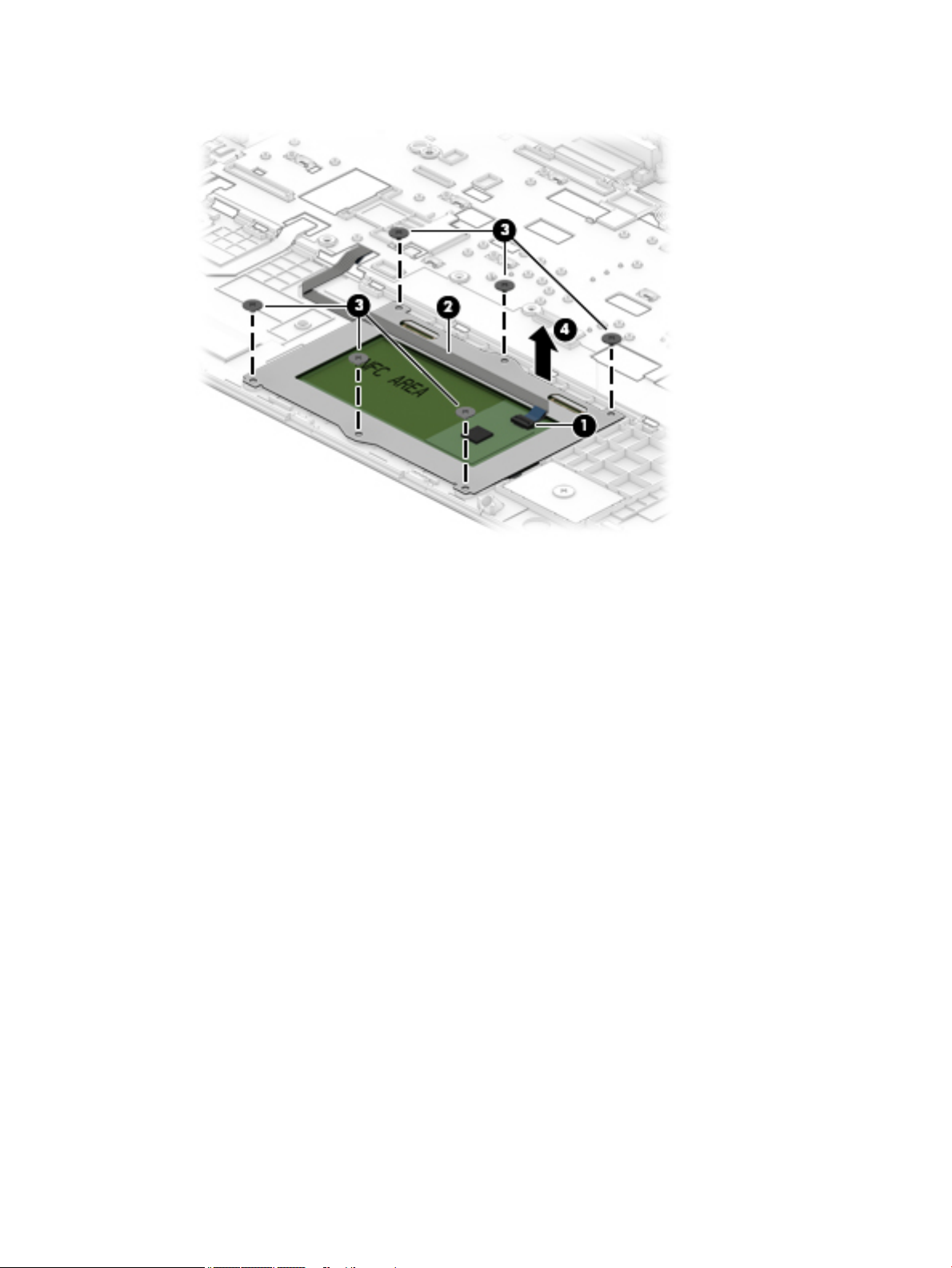
5. Lift the TouchPad o the top cover (4).
Reverse this procedure to install the TouchPad assembly.
Component replacement procedures 51
Page 62

Card reader board
Description Spare part number
Card reader board assembly L02277-001
Card reader board cable (included in Cable Kit) L01082-001
Before removing the card reader board, follow these steps:
1. Shut down the computer. If you are unsure whether the computer is o or in Hibernation, turn the
computer on, and then shut it down through the operating system.
2. Place the computer in “Battery Safe mode” (Battery Safe mode on page 27).
3. Disconnect all external devices connected to the computer.
4. Disconnect the power from the computer by rst unplugging the power cord from the AC outlet, and
then unplugging the AC adapter from the computer.
5. Remove the following components:
a. Service doors (Service doors on page 28)
b. Hard drive (Hard drive on page 34)
c. Keyboard (Keyboard on page 37)
d. Top cover (Top cover on page 41)
Remove the card reader board:
1. Position the computer upright on a at surface and open the display as far as possible.
2. Disconnect the cable from the system board ZIF connector (1).
3. Remove the 2 Torx T8 2.5×4.0 screws (2) that secure the board to the computer.
4. Lift the board out of the computer (3).
Reverse this procedure to install the card reader board.
52 Chapter 6 Removal and replacement procedures for Authorized Service Provider parts
Page 63

Fan
Description Spare part number
Fan L01088-001
NOTE: To properly ventilate the computer, allow at least 7.6 cm (3.0 in) of clearance on the sides of the
computer. The computer uses an electric fan for ventilation. The fan is controlled by a temperature sensor and
is designed to turn on automatically when high temperature conditions exist. These conditions are aected by
high external temperatures, system power consumption, power management/battery conservation
congurations, battery fast charging, and software requirements. Exhaust air is displaced through the
ventilation grill.
Before removing the fan, follow these steps:
1. Shut down the computer. If you are unsure whether the computer is o or in Hibernation, turn the
computer on, and then shut it down through the operating system.
2. Place the computer in “Battery Safe mode” (Battery Safe mode on page 27).
3. Disconnect all external devices connected to the computer.
4. Disconnect the power from the computer by rst unplugging the power cord from the AC outlet and then
unplugging the AC adapter from the computer.
5. Remove the battery (Battery on page 57), and then remove the following components:
a. Service doors (Service doors on page 28).
b. Hard drive (Hard drive on page 34)
c. Keyboard (Keyboard on page 37)
d. Top cover (Top cover on page 41)
To remove the fan:
1. Position the computer upright on a at surface and open the display as far as possible.
2. Disconnect the fan cable (1) from the system board.
3. Remove the display cable from atop the screw (2).
4. Remove the two Torx T8 2.5×5.0 screws (3) that secure the fan to the computer.
Component replacement procedures 53
Page 64

5. Lift the fan out of the computer (4).
Reverse this procedure to install the fan.
54 Chapter 6 Removal and replacement procedures for Authorized Service Provider parts
Page 65

Hard drive cable
Description Spare part number
Hard drive cable (included in Hard Drive Hardware Kit) L01083-001
Before removing the hard drive cable, follow these steps:
1. Shut down the computer. If you are unsure whether the computer is o or in Hibernation, turn the
computer on, and then shut it down through the operating system.
2. Place the computer in “Battery Safe mode” (Battery Safe mode on page 27).
3. Disconnect all external devices connected to the computer.
4. Disconnect the power from the computer by rst unplugging the power cord from the AC outlet and then
unplugging the AC adapter from the computer.
5. Remove the battery (Battery on page 57), and then remove the following components:
a. Service doors (Service doors on page 28).
b. Hard drive (Hard drive on page 34)
c. Keyboard (Keyboard on page 37)
d. Top cover (Top cover on page 41)
To remove the hard drive cable:
1. Position the computer upright on a at surface and open the display as far as possible.
2. Disconnect the cable from the ZIF connector on the system board (1).
3. Remove the cable from the clip (2), and then route the cable through the hole and out the bottom of the
computer (3).
Reverse this procedure to install the hard drive cable.
Component replacement procedures 55
Page 66

RTC battery
Description Spare part number
RTC battery not spared
Before removing the RTC battery, follow these steps:
1. Shut down the computer. If you are unsure whether the computer is o or in Hibernation, turn the
2. Place the computer in “Battery Safe mode” (Battery Safe mode on page 27).
3. Disconnect all external devices connected to the computer.
4. Disconnect the power from the computer by rst unplugging the power cord from the AC outlet, and
5. Remove the following components:
computer on, and then shut it down through the operating system.
then unplugging the AC adapter from the computer.
a. Service doors (Service doors on page 28).
b. Hard drive (Hard drive on page 34)
c. Keyboard (Keyboard on page 37)
d. Top cover (Top cover on page 41)
Remove the RTC battery:
1. Position the computer upright on a at surface and open the display as far as possible.
2. Use a tool to pry the battery out of the socket (1).
3. Remove the battery from the system board (2).
Reverse this procedure to install the RTC battery.
56 Chapter 6 Removal and replacement procedures for Authorized Service Provider parts
Page 67

Battery
Description Spare part number
Battery, 4-cell, 48 WHr, 4.21 Ah 851610-855
Before removing the battery, follow these steps:
1. Shut down the computer. If you are unsure whether the computer is o or in Hibernation, turn the
computer on, and then shut it down through the operating system.
2. Place the computer in “Battery Safe mode” (Battery Safe mode on page 27).
3. Disconnect all external devices connected to the computer.
4. Disconnect the power from the computer by rst unplugging the power cord from the AC outlet, and
then unplugging the AC adapter from the computer.
5. Remove the following components:
a. Service doors (Service doors on page 28).
b. Hard drive (Hard drive on page 34)
c. Keyboard (Keyboard on page 37)
d. Top cover (Top cover on page 41)
e. Card reader board (Card reader board on page 52)
To remove the battery:
1. Position the computer upright on a at surface and open the display as far as possible.
2. Remove the Torx T8 2.5×5.0 screw (1) that secures the battery to the computer.
3. Rotate the bottom of the battery upward (2), and then lift the battery out of the computer (3).
Reverse this procedure to install the battery.
Component replacement procedures 57
Page 68

USB board
Description Spare part number
USB board L02275-001
USB board cable (included in Cable Kit) L01082-001
Before removing the USB board, follow these steps:
1. Shut down the computer. If you are unsure whether the computer is o or in Hibernation, turn the
2. Place the computer in “Battery Safe mode” (Battery Safe mode on page 27).
3. Disconnect all external devices connected to the computer.
4. Disconnect the power from the computer by rst unplugging the power cord from the AC outlet, and
5. Remove the following components:
computer on, and then shut it down through the operating system.
then unplugging the AC adapter from the computer.
a. Service doors (Service doors on page 28).
b. Hard drive (Hard drive on page 34)
c. Keyboard (Keyboard on page 37)
d. Top cover (Top cover on page 41)
e. Card reader board (Card reader board on page 52)
f. Battery (Battery on page 57)
Remove the USB board:
1. Position the computer upright on a at surface and open the display as far as possible.
2. Disconnect the cable from the ZIF connector on the USB board (1).
3. Use a tool to pry the side of the board near the fan upward (2), and then pull the board away from the
tab that secures it (3).
58 Chapter 6 Removal and replacement procedures for Authorized Service Provider parts
Page 69

4. Remove the USB board from the computer (4).
Reverse this procedure to install the USB board.
Component replacement procedures 59
Page 70

System board
NOTE: All system board spare part kits include replacement thermal material.
All system boards use the following part numbers:
xxxxxx-001: Non-Windows operating systems
xxxxxx-601: Windows 10 operating system
Description Spare part number
System board with processor and 2 GB of discrete graphics:
Intel Core i7-8550U processor L02274-xxx
Intel Core i5-8250U processor L02273-xxx
Intel Core i7-7500U processor L02272-xxx
Intel Core i5-7200U processor L02271-xxx
Before removing the system board, follow these steps:
1. Shut down the computer. If you are unsure whether the computer is o or in Hibernation, turn the
computer on, and then shut it down through the operating system.
2. Place the computer in “Battery Safe mode” (Battery Safe mode on page 27).
3. Disconnect all external devices connected to the computer.
4. Disconnect the power from the computer by rst unplugging the power cord from the AC outlet, and
then unplugging the AC adapter from the computer.
5. Remove the following components:
a. Service doors (Service doors on page 28).
b. Hard drive (Hard drive on page 34)
c. Keyboard (Keyboard on page 37)
d. Top cover ( Top cover on page 41)
e. Card reader board (Card reader board on page 52)
f. Battery (Battery on page 57)
When replacing the system board, be sure to remove the following components (as applicable) from the
defective system board and install on the replacement system board:
●
Memory modules (Memory modules on page 30)
●
WLAN/Bluetooth module (WLAN/Bluetooth combo card on page 32)
●
M.2 solid-state drive (M.2 solid-state drive on page 36)
Remove the system board:
1. Position the computer upright on a at surface and open the display as far as possible.
60 Chapter 6 Removal and replacement procedures for Authorized Service Provider parts
Page 71

2. Disconnect the following cables from the system board:
(1): Display cable
(2): Power connector cable
(3): Hard drive connector cable (ZIF)
3. Remove the 2 Torx T8 2.5×4.0 screws (1) that secure the system board to the computer.
4. Lift the bracket from atop the USB-Type C port (2).
The USB bracket is available using spare part number L01051-001.
5. Rotate the left side of the system board upward (3).
Component replacement procedures 61
Page 72

6. Pull the system board away from the connectors on the side of the chassis to remove it from the
computer (4).
Reverse this procedure to install the system board.
62 Chapter 6 Removal and replacement procedures for Authorized Service Provider parts
Page 73

Heat sink assembly
All heat sink assembly spare part kits include replacement thermal material.
Description Spare part number
Heat sink L01086-001
Before removing the heat sink assembly, follow these steps:
1. Shut down the computer. If you are unsure whether the computer is o or in Hibernation, turn the
computer on, and then shut it down through the operating system.
2. Place the computer in “Battery Safe mode” (Battery Safe mode on page 27).
3. Disconnect all external devices connected to the computer.
4. Disconnect the power from the computer by rst unplugging the power cord from the AC outlet, and
then unplugging the AC adapter from the computer.
5. Remove the following components:
a. Service doors (Service doors on page 28).
b. Hard drive (Hard drive on page 34)
c. Keyboard (Keyboard on page 37)
d. Top cover (Top cover on page 41)
e. Card reader board (Card reader board on page 52)
f. Battery (Battery on page 57)
g. System board (System board on page 60)
Remove the heat sink assembly:
1. Position the system board upside-down.
2. In the order indicated on the heat sink, loosen the 6 captive Phillips screws (1) that secure the heat sink
to the system board.
Component replacement procedures 63
Page 74

3. Lift the heat sink from the system board (2).
NOTE: Thoroughly clean thermal material from the surfaces of the system board components (1)(3)
and the heat sink (2)(4) each time you remove the heat sink. All heat sink and processor spare part kits
include thermal material.
Reverse this procedure to install the heat sink assembly.
64 Chapter 6 Removal and replacement procedures for Authorized Service Provider parts
Page 75

Display assembly
Non-touch displays are spared only at the subcomponent level. Non-touch assemblies are not spared as
whole units.
Before disassembling the display assembly, follow these steps:
1. Shut down the computer. If you are unsure whether the computer is o or in Hibernation, turn the
computer on, and then shut it down through the operating system.
2. Place the computer in “Battery Safe mode” (Battery Safe mode on page 27).
3. Disconnect all external devices connected to the computer.
4. Disconnect the power from the computer by rst unplugging the power cord from the AC outlet, and
then unplugging the AC adapter from the computer.
5. Remove the following components:
a. Service doors (Service doors on page 28).
b. Hard drive (Hard drive on page 34)
c. Keyboard (Keyboard on page 37)
d. Top cover (Top cover on page 41)
Disassemble the display assembly:
1. Position the computer upright on a at surface and open the display as far as possible.
2. Flex the top (1) of the bezel, the inside edges of the left and right sides (2), and then the right side of the
bottom (3) and the left side of the bottom (4) of the bezel until it disengages from the display enclosure.
TIP: The bottom, inside of the bezel is secured to the display enclosure with double-sided adhesive.
When removing the bezel, be sure to remove the tape from the bezel so that it remains connected to the
display.
Component replacement procedures 65
Page 76
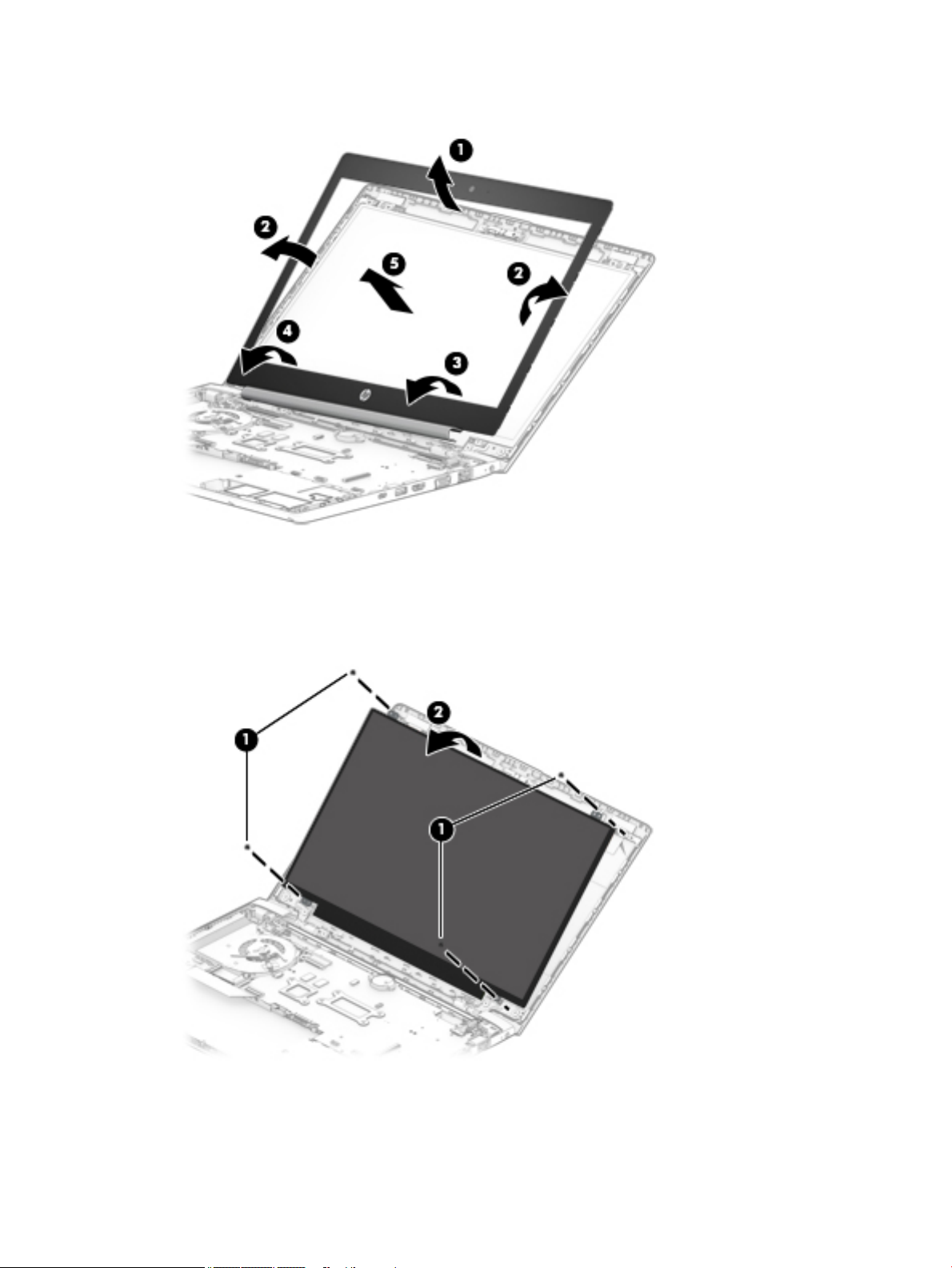
3. Remove the display bezel (5).
4. If it is necessary to remove or replace the display panel, remove the 4 Phillips M2.0×2.0 screws (1) that
secure the display panel to the enclosure.
5. Rotate the display panel onto the keyboard (2) to gain access to the display cable connector on the back
of the panel.
6. Lift the tape from atop the connector on the display panel (1), lift the connector latch (2), and then
disconnect the cable from the panel (3).
66 Chapter 6 Removal and replacement procedures for Authorized Service Provider parts
Page 77

7. Remove the panel (4).
8. To remove the display enclosure, position the computer with the display enclosure lying on a at surface
and the computer upward at a 90 degree angle.
9. Remove the 6 Phillips broad head M2.5×2.5 screws (1) from the bottom of the display hinges and the 2
Phillips M2.0×2.0 screws (2) from the top of the display hinges.
10. Separate the display enclosure from the hinges (3).
Component replacement procedures 67
Page 78

11. To remove the display hinges and brackets, remove the 4 Torx T8 2.5×4.0 screws (1) that secure the
hinges to the computer, and then slide the hinges toward each other to remove them (2).
12. If it is necessary to replace the WLAN antennas, peel the antennas from the display enclosure (1),
remove the cables from the clips in the sides of the enclosure (2), and then lift the cables and antennas
from the enclosure (3).
68 Chapter 6 Removal and replacement procedures for Authorized Service Provider parts
Page 79

13. If it is necessary to remove or replace the HD camera, disconnect the cable from the camera (1), and
then peel the camera module up to remove it from the adhesive that secures it to the enclosure (2) .
14. If it is necessary to remove or replace the HD display/camera cable, remove the cable from under the tab
that secures it to the enclosure (1), and then remove the cable from the display enclosure (2).
Reverse this procedure to reassemble the touch display assembly.
Component replacement procedures 69
Page 80

Power cable
Description Spare part number
Power cable L07857-001
Before removing the power cable, follow these steps:
1. Shut down the computer. If you are unsure whether the computer is o or in Hibernation, turn the
2. Place the computer in “Battery Safe mode” (Battery Safe mode on page 27).
3. Disconnect all external devices connected to the computer.
4. Disconnect the power from the computer by rst unplugging the power cord from the AC outlet, and
5. Remove the following components:
computer on, and then shut it down through the operating system.
then unplugging the AC adapter from the computer.
a. Service door (Service doors on page 28).
b. Hard drive (Hard drive on page 34)
c. Keyboard (Keyboard on page 37)
d. Top cover (Top cover on page 41)
e. Card reader board (Card reader board on page 52)
f. Battery (Battery on page 57)
g. Display assembly right hinge Display assembly on page 65)
Remove the power cable:
1. Disconnect the cable from the system board (1).
2. Remove the power cable from the computer (2).
Reverse this procedure to install the power cable.
70 Chapter 6 Removal and replacement procedures for Authorized Service Provider parts
Page 81

7 Computer Setup (BIOS), TPM, and HP Sure
Start
Using Computer Setup
Computer Setup, or Basic Input/Output System (BIOS), controls communication between all the input and
output devices on the system (such as disk drives, display, keyboard, mouse, and printer). Computer Setup
includes settings for the types of devices installed, the startup sequence of the computer, and the amount of
system and extended memory.
NOTE: Use extreme care when making changes in Computer Setup. Errors can prevent the computer from
operating properly.
Starting Computer Setup
▲
Turn on or restart the computer, and when the HP logo appears, press f10 to enter Computer Setup.
Using a USB keyboard or USB mouse to start Computer Setup (BIOS)
You can start Computer Setup by using a keyboard or mouse connected to a USB port, but you must rst
disable FastBoot.
1. Turn on or restart the computer, and when the HP logo appears, press f9 to enter the Boot Device
Options menu.
2. Clear the check box for Fast Boot.
3. To save your changes and exit, select the Save icon in the lower-right corner of the screen, and then
follow the on-screen instructions.
– or –
Select Main, select Save Changes and Exit, and then press enter.
Your changes go into eect when the computer restarts.
Navigating and selecting in Computer Setup
●
To select a menu or a menu item, use the tab key and the keyboard arrow keys and then press enter, or
use a pointing device to select the item.
●
To scroll up and down, select the up arrow or the down arrow in the upper-right corner of the screen, or
use the up arrow key or the down arrow key on the keyboard.
●
To close open dialog boxes and return to the main Computer Setup screen, press esc, and then follow
the on-screen instructions.
Using Computer Setup 71
Page 82

To exit Computer Setup menus, choose one of the following methods:
●
To exit Computer Setup menus without saving your changes:
Select the Exit icon in the lower-right corner of the screen, and then follow the on-screen instructions.
– or –
Select Main, select Ignore Changes and Exit, and then press enter.
●
To save your changes and exit Computer Setup menus:
Select the Save icon in the lower-right corner of the screen, and then follow the on-screen instructions.
– or –
Select Main, select Save Changes and Exit, and then press enter.
Your changes go into eect when the computer restarts.
Restoring factory settings in Computer Setup
NOTE: Restoring defaults will not change the hard drive mode.
To return all settings in Computer Setup to the values that were set at the factory, follow these steps:
1. Start Computer Setup. See Starting Computer Setup on page 71.
2. Select Main, and then select Apply Factory Defaults and Exit.
NOTE: On select products, the selections may display Restore Defaults instead of Apply Factory
Defaults and Exit.
3. Follow the on-screen instructions.
4. To save your changes and exit, select the Save icon in the lower-right corner of the screen, and then
follow the on-screen instructions.
– or –
Select Main, select Save Changes and Exit, and then press enter.
Your changes go into eect when the computer restarts.
NOTE: Your password settings and security settings are not changed when you restore the factory settings.
Updating the BIOS
Updated versions of the BIOS may be available on the HP website.
Most BIOS updates on the HP website are packaged in compressed les called SoftPaqs.
Some download packages contain a le named Readme.txt, which contains information regarding installing
and troubleshooting the le.
Determining the BIOS version
To decide whether you need to update Computer Setup (BIOS), rst determine the BIOS version on your
computer.
BIOS version information (also known as ROM date and System BIOS) can be accessed by pressing fn+esc (if
you are already in Windows) or by using Computer Setup.
72 Chapter 7 Computer Setup (BIOS), TPM, and HP Sure Start
Page 83

1. Start Computer Setup. See Starting Computer Setup on page 71.
2. Select Main, and then select System Information.
3. To exit Computer Setup without saving your changes, select the Exit icon in the lower-right corner of the
screen, and then follow the on-screen instructions.
– or –
Select Main, select Ignore Changes and Exit, and then press enter.
To check for later BIOS versions, see Downloading a BIOS update on page 73.
Downloading a BIOS update
CAUTION: To reduce the risk of damage to the computer or an unsuccessful installation, download and
install a BIOS update only when the computer is connected to reliable external power using the AC adapter. Do
not download or install a BIOS update while the computer is running on battery power, docked in an optional
docking device, or connected to an optional power source. During the download and installation, follow these
instructions:
Do not disconnect power on the computer by unplugging the power cord from the AC outlet.
Do not shut down the computer or initiate Sleep.
Do not insert, remove, connect, or disconnect any device, cable, or cord.
1. Type support in the taskbar search box, and then select the HP Support Assistant app.
– or –
Select the question mark icon in the taskbar.
2. Select Updates, and then select Check for updates and messages.
3. Follow the on-screen instructions.
4. At the download area, follow these steps:
a. Identify the most recent BIOS update and compare it to the BIOS version currently installed on your
computer. Make a note of the date, name, or other identier. You may need this information to
locate the update later, after it has been downloaded to your hard drive.
b. Follow the on-screen instructions to download your selection to the hard drive.
Make a note of the path to the location on your hard drive where the BIOS update is downloaded.
You will need to access this path when you are ready to install the update.
NOTE: If you connect your computer to a network, consult the network administrator before installing
any software updates, especially system BIOS updates.
BIOS installation procedures vary. Follow any instructions that are displayed on the screen after the download
is complete. If no instructions are displayed, follow these steps:
1. Type file in the taskbar search box, and then select File Explorer.
2. Select your hard drive designation. The hard drive designation is typically Local Disk (C:).
3. Using the hard drive path you recorded earlier, open the folder that contains the update.
4. Double-click the le that has an .exe extension (for example, lename.exe).
The BIOS installation begins.
5. Complete the installation by following the on-screen instructions.
Using Computer Setup 73
Page 84

NOTE: After a message on the screen reports a successful installation, you can delete the downloaded le
from your hard drive.
Changing the boot order using the f9 prompt
To dynamically choose a boot device for the current startup sequence, follow these steps:
1. Access the Boot Device Options menu:
●
Turn on or restart the computer, and when the HP logo appears, press f9 to enter the Boot Device
Options menu.
2. Select a boot device, press enter, and then follow the on-screen instructions.
TPM BIOS settings (select products only)
IMPORTANT: Before enabling Trusted Platform Module (TPM) functionality on this system, you must ensure
that your intended use of TPM complies with relevant local laws, regulations and policies, and approvals or
licenses must be obtained if applicable. For any compliance issues arising from your operation/usage of TPM
which violates the above mentioned requirement, you shall bear all the liabilities wholly and solely. HP will
not be responsible for any related liabilities.
TPM provides additional security for your computer. You can modify the TPM settings in Computer Setup
(BIOS).
NOTE: If you change the TPM setting to Hidden, TPM is not visible in the operating system.
To access TPM settings in Computer Setup:
1. Start Computer Setup. See Starting Computer Setup on page 71.
2. Select Security, select TPM Embedded Security, and then follow the on-screen instructions.
Using HP Sure Start (select products only)
Select computer models are congured with HP Sure Start, a technology that monitors the computer's BIOS
for attacks or corruption. If the BIOS becomes corrupted or is attacked, HP Sure Start automatically restores
the BIOS to its previously safe state, without user intervention.
HP Sure Start is congured and already enabled so that most users can use the HP Sure Start default
conguration. The default conguration can be customized by advanced users.
To access the latest documentation on HP Sure Start, go to http://www.hp.com/support. Select Find your
product, and then follow the on-screen instructions.
74 Chapter 7 Computer Setup (BIOS), TPM, and HP Sure Start
Page 85

8 Using HP PC Hardware Diagnostics (UEFI)
HP PC Hardware Diagnostics is a Unied Extensible Firmware Interface (UEFI) that allows you to run diagnostic
tests to determine whether the computer hardware is functioning properly. The tool runs outside the
operating system so that it can isolate hardware failures from issues that are caused by the operating system
or other software components.
When HP PC Hardware Diagnostics (UEFI) detects a failure that requires hardware replacement, a 24-digit
Failure ID code is generated. This ID code can then be provided to support to help determine how to correct
the problem.
NOTE: To start diagnostics on a convertible computer, your computer must be in notebook mode and you
must use the keyboard attached.
To start HP PC Hardware Diagnostics (UEFI), follow these steps:
1. Turn on or restart the computer, and quickly press esc.
2. Press f2.
The BIOS searches three places for the diagnostic tools, in the following order:
a. Connected USB drive
NOTE: To download the HP PC Hardware Diagnostics (UEFI) tool to a USB drive, see Downloading
HP PC Hardware Diagnostics (UEFI) to a USB device on page 75.
b. Hard drive
c. BIOS
3. When the diagnostic tool opens, select the type of diagnostic test you want to run, and then follow the
on-screen instructions.
NOTE: If you need to stop a diagnostic test, press esc.
Downloading HP PC Hardware Diagnostics (UEFI) to a USB device
NOTE: The HP PC Hardware Diagnostics (UEFI) download instructions are provided in English only, and you
must use a Windows computer to download and create the HP UEFI support environment because only .exe
les are oered.
There are two options to download HP PC Hardware Diagnostics to a USB device.
Download the latest UEFI version
1. Go to http://www.hp.com/go/techcenter/pcdiags. The HP PC Diagnostics home page is displayed.
2. In the HP PC Hardware Diagnostics section, select the Download link, and then select Run.
Download any version of UEFI for a specic product
1. Go to http://www.hp.com/support.
2. Select Get software and drivers.
3. Enter the product name or number.
Downloading HP PC Hardware Diagnostics (UEFI) to a USB device 75
Page 86

4. Select your computer, and then select your operating system.
5. In the Diagnostic section, follow the on-screen instructions to select and download the UEFI version
you want.
Using Remote HP PC Hardware Diagnostics (UEFI) settings (select products only)
Your computer supports Remote HP PC Hardware Diagnostics (UEFI). This is a rmware (BIOS) feature that
downloads HP PC Hardware Diagnostics UEFI to your computer.
It executes the diagnostics on your computer, and then may upload results to a precongured server.
Using the Remote HP PC Hardware Diagnostics setting in Computer Setup (BIOS), you can perform the
following customizations:
●
Set a schedule for running diagnostics unattended. You can also start diagnostics immediately in
interactive mode by selecting Execute Remote HP PC Hardware Diagnostics.
●
Set the location for downloading the diagnostic tools. This feature provides access to the tools from the
HP website or from a server that has been precongured for use. Your computer does not require the
traditional local storage (such as a disk drive or USB ash drive) to run remote diagnostics.
●
Set a location for storing the test results. You can also set the user name and password settings used for
uploads.
●
Display status information about the diagnostics run previously.
Customizing Remote HP PC Hardware Diagnostics (UEFI) settings
1. Turn on or restart the computer, and when the HP logo appears, press f10 to enter Computer Setup.
2. Select Advanced, and then select Settings.
3. Make your customization selections.
4. Select Main, and then Save Changes and Exit to save your settings.
Your changes take eect when the computer restarts.
To access documentation on using Remote HP PC Hardware Diagnostics (UEFI) to congure a server for
remote diagnostics or to customize which diagnostic tests are run, go to http://www.hp.com/support. Select
Find your product, and then follow the on-screen instructions.
76 Chapter 8 Using HP PC Hardware Diagnostics (UEFI)
Page 87

9 Backing up, restoring, and recovering
This chapter provides information about the following processes. The information in the chapter is standard
procedure for most products.
●
Creating recovery media and backups
●
Restoring and recovering your system
For additional information, refer to the HP Support Assistant app.
▲
Type support in the taskbar search box, and then select the HP Support Assistant app.
‒ or –
Select the question mark icon in the taskbar.
IMPORTANT: If you will be performing recovery procedures on a tablet, the tablet battery must be at least
70% charged before you start the recovery process.
IMPORTANT: For a tablet with a detachable keyboard, connect the tablet to the keyboard base before
beginning any recovery process.
Creating recovery media and backups
The following methods of creating recovery media and backups are available on select products only. Choose
the available method according to your computer model.
●
Use HP Recovery Manager to create HP Recovery media after you successfully set up the computer. This
step creates a backup of the HP Recovery partition on the computer. The backup can be used to reinstall
the original operating system in cases where the hard drive is corrupted or has been replaced. For
information on creating recovery media, see Creating HP Recovery media (select products only)
on page 77. For information on the recovery options that are available using the recovery media, see
Using Windows tools on page 78.
●
Use Windows tools to create system restore points and create backups of personal information.
For more information, see Recovering using HP Recovery Manager on page 79.
NOTE: If storage is 32 GB or less, Microsoft System Restore is disabled by default.
●
On select products, use the HP Cloud Recovery Download Tool to create a bootable USB drive for your HP
recovery media. Go to https://support.hp.com/us-en/document/c05115630?openCLC=true, select your
country or region, and follow the on-screen instructions.
Creating HP Recovery media (select products only)
If possible, check for the presence of the Recovery partition and the Windows partition. Right-click the Start
menu, select File Explorer, and then select This PC.
●
If your computer does not list the Windows partition and the Recovery partition, you can obtain recovery
media for your system from support. You can nd contact information on the HP website. Go to
http://www.hp.com/support, select your country or region, and follow the on-screen instructions.
Creating recovery media and backups 77
Page 88

You can use Windows tools to create system restore points and create backups of personal information,
see Using Windows tools on page 78.
●
If your computer does list the Recovery partition and the Windows partition, you can use HP Recovery
Manager to create recovery media after you successfully set up the computer. HP Recovery media can be
used to perform system recovery if the hard drive becomes corrupted. System recovery reinstalls the
original operating system and software programs that were installed at the factory and then congures
the settings for the programs. HP Recovery media can also be used to customize the system or restore
the factory image if you replace the hard drive.
–
Only one set of recovery media can be created. Handle these recovery tools carefully, and keep
them in a safe place.
–
HP Recovery Manager examines the computer and determines the required storage capacity for
the media that will be required.
–
To create recovery discs, your computer must have an optical drive with DVD writer capability, and
you must use only high-quality blank DVD-R, DVD+R, DVD-R DL, or DVD+R DL discs. Do not use
rewritable discs such as CD±RW, DVD±RW, double-layer DVD±RW, or BD-RE (rewritable Blu-ray)
discs; they are not compatible with HP Recovery Manager software. Or, instead, you can use a highquality blank USB ash drive.
–
If your computer does not include an integrated optical drive with DVD writer capability, but you
would like to create DVD recovery media, you can use an external optical drive (purchased
separately) to create recovery discs. If you use an external optical drive, it must be connected
directly to a USB port on the computer; the drive cannot be connected to a USB port on an external
device, such as a USB hub. If you cannot create DVD media yourself, you can obtain recovery discs
for your computer from HP. You can nd contact information on the HP website. Go to
http://www.hp.com/support, select your country or region, and follow the on-screen instructions.
–
Be sure that the computer is connected to AC power before you begin creating the recovery media.
–
The creation process can take an hour or more. Do not interrupt the creation process.
–
If necessary, you can exit the program before you have nished creating all of the recovery DVDs.
HP Recovery Manager will nish burning the current DVD. The next time you start HP Recovery
Manager, you will be prompted to continue.
To create HP Recovery media:
IMPORTANT: For a tablet with a detachable keyboard, connect the tablet to the keyboard base before
beginning these steps.
1. Type recovery in the taskbar search box, and then select HP Recovery Manager.
2. Select Create recovery media, and then follow the on-screen instructions.
If you ever need to recover the system, see Recovering using HP Recovery Manager on page 79.
Using Windows tools
You can create recovery media, system restore points, and backups of personal information using Windows
tools.
NOTE: If storage is 32 GB or less, Microsoft System Restore is disabled by default.
For more information and steps, see the Get help app.
▲ Select the Start button, and then select the Get Help app.
78 Chapter 9 Backing up, restoring, and recovering
Page 89

NOTE: You must be connected to the Internet to access the Get help app.
Restore and recovery
There are several options for recovering your system. Choose the method that best matches your situation
and level of expertise:
IMPORTANT: Not all methods are available on all products.
●
Windows oers several options for restoring from backup, refreshing the computer, and resetting the
computer to its original state. For more information see the Get help app.
▲ Select the Start button, and then select the Get Help app.
NOTE: You must be connected to the Internet to access the Get help app.
●
If you need to correct a problem with a preinstalled application or driver, use the Reinstall drivers and/or
applications option (select products only) of HP Recovery Manager to reinstall the individual application
or driver.
▲ Type recovery in the taskbar search box, select HP Recovery Manager, select Reinstall drivers
and/or applications
●
If you want to recover the Windows partition to original factory content, you can choose the System
Recovery option from the HP Recovery partition (select products only) or use the HP Recovery media.
For more information, see Recovering using HP Recovery Manager on page 79. If you have not already
created recovery media, see Creating HP Recovery media (select products only) on page 77.
, and then follow the on-screen instructions.
●
On select products, if you want to recover the computer's original factory partition and content, or if you
have replaced the hard drive, you can use the Factory Reset option of HP Recovery media. For more
information, see Recovering using HP Recovery Manager on page 79.
●
On select products, if you want to remove the Recovery partition to reclaim hard drive space, HP
Recovery Manager oers the Remove Recovery Partition option.
For more information, see Removing the HP Recovery partition (select products only) on page 81.
Recovering using HP Recovery Manager
HP Recovery Manager software allows you to recover the computer to its original factory state by using the
HP Recovery media that you either created or that you obtained from HP, or by using the HP Recovery
partition (select products only). If you have not already created recovery media, see Creating HP Recovery
media (select products only) on page 77.
What you need to know before you get started
●
HP Recovery Manager recovers only software that was installed at the factory. For software not provided
with this computer, you must either download the software from the manufacturer's website or reinstall
the software from the media provided by the manufacturer.
IMPORTANT: Recovery through HP Recovery Manager should be used as a nal attempt to correct
computer issues.
●
HP Recovery media must be used if the computer hard drive fails. If you have not already created
recovery media, see Creating HP Recovery media (select products only) on page 77.
Restore and recovery 79
Page 90

●
To use the Factory Reset option (select products only), you must use HP Recovery media. If you have not
already created recovery media, see Creating HP Recovery media (select products only) on page 77.
●
If your computer does not allow the creation of HP Recovery media or if the HP Recovery media does not
work, you can obtain recovery media for your system from support. You can nd contact information
from the HP website. Go to http://www.hp.com/support, select your country or region, and follow the
on-screen instructions.
IMPORTANT: HP Recovery Manager does not automatically provide backups of your personal data. Before
beginning recovery, back up any personal data you want to retain.
Using HP Recovery media, you can choose from one of the following recovery options:
NOTE: Only the options available for your computer display when you start the recovery process.
●
System Recovery—Reinstalls the original operating system, and then congures the settings for the
programs that were installed at the factory.
●
Factory Reset—Restores the computer to its original factory state by deleting all information from the
hard drive and re-creating the partitions. Then it reinstalls the operating system and the software that
was installed at the factory.
The HP Recovery partition (select products only) allows System Recovery only.
Using the HP Recovery partition (select products only)
The HP Recovery partition allows you to perform a system recovery without the need for recovery discs or a
recovery USB ash drive. This type of recovery can be used only if the hard drive is still working.
To start HP Recovery Manager from the HP Recovery partition:
IMPORTANT: For a tablet with a detachable keyboard, connect the tablet to the keyboard base before
beginning these steps (select products only).
1. Type recovery in the taskbar search box, select HP Recovery Manager, and then select Windows
Recovery Environment
‒ or –
For computers or tablets with keyboards attached, press f11 while the computer boots, or press and
hold f11 as you press the power button.
For tablets without keyboards:
●
Turn on or restart the tablet, and then quickly hold down the volume up button; then select f11.
‒ or –
●
Turn on or restart the tablet, and then quickly hold down the volume down button; then select f11.
2. Select Troubleshoot from the boot options menu.
3. Select Recovery Manager, and then follow the on-screen instructions.
.
Using HP Recovery media to recover
You can use HP Recovery media to recover the original system. This method can be used if your system does
not have an HP Recovery partition or if the hard drive is not working properly.
80 Chapter 9 Backing up, restoring, and recovering
Page 91

1. If possible, back up all personal les.
2. Insert the HP Recovery media, and then restart the computer.
NOTE: If the computer does not automatically restart in HP Recovery Manager, change the computer
boot order. See Changing the computer boot order on page 81.
3. Follow the on-screen instructions.
Changing the computer boot order
If your computer does not restart in HP Recovery Manager, you can change the computer boot order, which is
the order of devices listed in BIOS where the computer looks for startup information. You can change the
selection to an optical drive or a USB
To change the boot order:
IMPORTANT: For a tablet with a detachable keyboard, connect the tablet to the keyboard base before
beginning these steps.
1. Insert the HP Recovery media.
2. Access the system Startup menu.
For computers or tablets with keyboards attached:
▲
Turn on or restart the computer or tablet, quickly press esc, and then press f9 for boot options.
ash drive.
For tablets without keyboards:
▲
Turn on or restart the tablet, and then quickly hold down the volume up button; then select f9.
‒ or –
Turn on or restart the tablet, and then quickly hold down the volume down button; then select f9.
3. Select the optical drive or USB ash drive from which you want to boot.
4. Follow the on-screen instructions.
Removing the HP Recovery partition (select products only)
HP Recovery Manager software allows you to remove the HP Recovery partition to free up hard drive space.
IMPORTANT: After you remove the HP Recovery partition, you will not be able to perform System Recovery
or create HP Recovery media from the HP Recovery partition. So before you remove the Recovery partition,
create HP Recovery media; see Creating HP Recovery media (select products only) on page 77.
NOTE: The Remove Recovery Partition option is only available on products that support this function.
Follow these steps to remove the HP Recovery partition:
1. Type recovery in the taskbar search box, and then select HP Recovery Manager.
2. Select Remove Recovery Partition, and then follow the on-screen instructions.
Restore and recovery 81
Page 92

10 Specications
Computer specications
Metric U.S.
Dimensions
Depth 238.0 mm 9.37 in
Width 336.0 mm 13.23 in
Height 19.95 mm 0.79 in
Weight
Non-touch, M.2 SSD, 1.635 kg 3.6 lbs
Non-touch, hard drive 1.735 kg 3.82 lbs
Input power
Operating voltage 19.0 V dc @ 4.74 A – 90 W or 18.5 V dc @ 3.5 A - 65 W
Operating current 4.74 A or 3.5 A
Temperature
Operating (not writing to optical disc) 0°C to 35°C 32°F to 95°F
Operating (writing to optical disc) 5°C to 35°C 41°F to 95°F
Nonoperating -20°C to 60°C -4°F to 140°F
Relative humidity
Operating 10% to 90%
Nonoperating 5% to 95%
Maximum altitude (unpressurized)
Operating (14.7 to 10.1 psia) -15 m to 3,048 m 50 ft to 10,000 ft
Nonoperating (14.7 to 4.4 psia) -15 m to 12,192 m -50 ft to 40,000 ft
Shock
Operating 125 g, 2 ms, half-sine
Nonoperating 200 g, 2 ms, half-sine
Random vibration
Operating 0.75 g zero-to-peak, 10 Hz to 500 Hz, 0.25 oct/min sweep rate
Nonoperating 1.50 g zero-to-peak, 10 Hz to 500 Hz, 0.5 oct/min sweep rate
NOTE: Applicable product safety standards specify thermal limits for plastic surfaces. The computer operates well within this range
of temperatures.
82 Chapter 10 Specications
Page 93

35.6-cm (14.0-in) display specications
Metric U.S.
Active diagonal size 35.6-cm 14.0-in
Resolution HD: 1366x768
FHD: 1920x1080
Surface treatment Anti-glare
Panel Width 3.0 mm
Brightness FHD: 220 nits
Viewing angle UWVA
Backlight LED
Aspect ratio 16:9
Hard drive specications
1-TB* 500-GB*
Dimensions
Height 7.0 mm 7.0 mm
Width 70 mm 70 mm
Weight 115 g 101 g or 95 g
Interface type SATA SATA
Transfer rate 100 MB/sec 100 MB/sec
Security ATA security ATA security
Seek times (typical read, including setting)
Single track 1.4 ms 3 ms
Average 10 ms 13 ms
Maximum 12 ms 24 ms
Logical blocks 1,938,921,461 1,048,576,000
Disc rotational speed 5400 rpm 7200 rpm or 5400 rpm
Operating temperature
*1 GB = 1 billion bytes when referring to hard drive storage capacity. Actual accessible capacity is less. Actual drive specications may
dier slightly.
NOTE: Certain restrictions and exclusions apply. Contact technical support for details.
35.6-cm (14.0-in) display specications 83
Page 94

Solid-state drive specications
128-GB* 256-GB* 512-GB*
Height 1.0 mm 1.0 mm 1.0 mm
Length 50.8 mm 50.8 mm 50.8 mm
Width 28.9 mm 28.9 mm 28.9 mm
Weight < 10 g < 10 g < 10 g
Transfer rate
Sequential read up to 2150 MB/sec up to 2150 MB/sec up to 2150 MB/sec
Random read Up to 300,000 IOPs Up to 300,000 IOPs Up to 300,000 IOPs
Sequential write up to 1260 MB/sec up to 1550 MB/sec up to 1550 MB/sec
Random write Up to 100,000 IOPs Up to 100,000 IOPs Up to 100,000 IOPs
Interface type SATA-3 PCIe PCIe
Ready time, maximum (to not busy) 1.0 ms < 1.0 ms < 1.0 ms
Access times, logical 0.1 ms 0.1 ms 0.1 ms
Total logical sectors 234,441,648 468,883,296 1,000,215,216
Operating temperature 0°C to 70°C (32°F to 158°F)
*1 GB = 1 billion bytes when referring to hard drive storage capacity. Actual accessible capacity is less. Actual drive specications may
dier slightly.
NOTE: Certain restrictions and exclusions apply. Contact technical support for details.
84 Chapter 10 Specications
Page 95

11 Statement of memory volatility
The purpose of this chapter is to provide general information regarding nonvolatile memory in HP Business
computers. This chapter also provides general instructions for restoring nonvolatile memory that can contain
personal data after the system has been powered o and the hard drive has been removed.
HP Business computer products that use Intel®-based or AMD®-based system boards contain volatile DDR
memory. The amount of nonvolatile memory present in the system depends upon the system
Intel-based and AMD-based system boards contain nonvolatile memory subcomponents as originally shipped
from HP, assuming that no subsequent modications have been made to the system and assuming that no
applications, features, or functionality have been added to or installed on the system.
Following system shutdown and removal of all power sources from an HP Business computer system,
personal data can remain on volatile system memory (DIMMs) for a nite period of time and will also remain
in nonvolatile memory. Use the steps below to remove personal data from the computer, including the
nonvolatile memory found in Intel-based and AMD-based system boards.
NOTE: If your tablet has a keyboard base, connect to the keyboard base before beginning steps in this
chapter.
Current BIOS steps
1. Follow steps (a) through (l) below to restore the nonvolatile memory that can contain personal data.
Restoring or reprogramming nonvolatile memory that does not store personal data is neither necessary
nor recommended.
conguration.
a. Turn on or restart the computer, and then press esc while the “Press the ESC key for Startup Menu”
message is displayed at the bottom of the screen.
NOTE: If the system has a BIOS administrator password, enter the password at the prompt.
b. Select Main, select Apply Factory Defaults and Exit, and then select Yes to load defaults.
The computer will reboot.
c. During the reboot, press esc while the “Press the ESC key for Startup Menu” message is displayed
at the bottom of the screen.
NOTE: If the system has a BIOS administrator password, enter the password at the prompt.
d. Select the Security menu, select Restore Security Settings to Factory Defaults, and then select
Yes to restore security level defaults.
The computer will reboot.
e. During the reboot, press esc while the “Press the ESC key for Startup Menu” message is displayed
at the bottom of the screen.
NOTE: If the system has a BIOS administrator password, enter the password at the prompt.
f. If an asset or ownership tag is set, select the Security menu and scroll down to the Utilities menu.
Select System IDs, and then select Asset Tracking Number. Clear the tag, and then make the
selection to return to the prior menu.
85
Page 96

g. If a DriveLock password is set, select the Security menu, and scroll down to Hard Drive Utilities
under the Utilities menu. Select Hard Drive Utilities, select DriveLock, then uncheck the checkbox
for DriveLock password on restart. Select OK to proceed.
h. Select the Main menu, and then select Reset BIOS Security to factory default. Click Yes at the
warning message.
The computer will reboot.
i. During the reboot, press esc while the “Press the ESC key for Startup Menu” message is displayed
at the bottom of the screen.
NOTE: If the system has a BIOS administrator password, enter the password at the prompt.
j. Select the Main menu, select Apply Factory Defaults and Exit, select Yes to save changes and exit,
and then select Shutdown.
k. Reboot the system. If the system has a Trusted Platform Module (TPM) and/or ngerprint reader,
one or two prompts will appear—one to clear the TPM and the other to Reset Fingerprint Sensor;
press or tap F1 to accept or F2 to reject.
l. Remove all power and system batteries for at least 24 hours.
2. Complete one of the following:
●
Remove and retain the storage drive.
– or –
●
Clear the drive contents by using a third party utility designed to erase data from an SSD.
– or –
●
Clear the contents of the drive by using the following BIOS Setup Secure Erase command option
steps:
IMPORTANT: If you clear data using Secure Erase, it cannot be recovered.
a. Turn on or restart the computer, and then press esc while the “Press the ESC key for Startup Menu”
message is displayed at the bottom of the screen.
b. Select the Security menu and scroll down to the Utilities menu.
c. Select Hard Drive Utilities.
d. Under Utilities, select Secure Erase, select the hard drive storing the data you want to clear, and
then follow the on-screen instructions to continue.
86 Chapter 11 Statement of memory volatility
Page 97

Nonvolatile memory usage
Nonvolatile
Memory Type Amount (Size)
HP Sure Start ash
(select models
only)
Real Time Clock
(RTC) battery
backed-up CMOS
conguration
memory
8 MBytes No Yes Provides
256 Bytes No Yes Stores system
Does this
memory
store
customer
data?
Does this
memory
retain data
when power
is removed?
What is the
purpose of this
memory?
protected
backup of
critical System
BIOS code, EC
rmware, and
critical
computer
conguration
data for select
platforms that
support HP
Sure Start.
For more
information,
see Using HP
Sure Start
(select models
only)
on page 90.
date and time
and noncritical
data.
How is data input into this
memory?
Data cannot be written to this
device via the host processor.
The content is managed
solely by the HP Sure Start
Embedded Controller.
RTC battery backed-up CMOS
is programmed using the
Computer Setup (BIOS), or
changing the Microsoft
Windows date & time.
How is this memory
write-protected?
This memory is protected
by the HP Sure Start
Embedded Controller.
This memory is not writeprotected.
Controller (NIC)
EEPROM
DIMM Serial
Presence Detect
(SPD)
conguration data
System BIOS 9 MBytes Yes Yes Stores system
64 KBytes (not
customer
accessible)
256 Bytes per
memory
module, 128
Bytes
programmable
(not customer
accessible)
No Yes Stores NIC
conguration
and NIC
rmware.
No Yes Stores memory
module
information.
BIOS code and
computer
conguration
data.
NIC EEPROM is programmed
using a utility from the NIC
vendor that can be run from
DOS.
DIMM SPD is programmed by
the memory vendor.
System BIOS code is
programmed at the factory.
Code is updated when the
system BIOS is updated.
Conguration data and
settings are input using the
Computer Setup (BIOS) or a
custom utility.
A utility is required to
write data to this memory
and is available from the
NIC vendor. Writing data
to this ROM in an
inappropriate manner will
render the NIC nonfunctional.
Data cannot be written to
this memory when the
module is installed in a
computer. The specic
write-protection method
varies by memory vendor.
NOTE: Writing data to
this ROM in an
inappropriate manner can
render the computer nonfunctional.
A utility is required for
writing data to this
memory and is available
on the HP website; go to
http://www.hp.com/
support. Select Find your
Nonvolatile memory usage 87
Page 98

Nonvolatile
Memory Type Amount (Size)
Does this
memory
store
customer
data?
Does this
memory
retain data
when power
is removed?
What is the
purpose of this
memory?
How is data input into this
memory?
How is this memory
write-protected?
product, and then follow
the on-screen
instructions.
Intel Management
Engine Firmware
(present only in
select Elite or Z
models. For more
information, go to
http://www.hp.com/
support. Select
Find your
product, and then
follow the onscreen
instructions.)
Bluetooth ash
(select products
only)
802.11 WLAN
EEPROM
1.5 MBytes or 7
MBytes
2 Mbit No Yes Stores
4 Kbit to 8 Kbit No Yes Stores
Yes Yes Stores
Management
Engine Code,
Settings,
Provisioning
Data and iAMT
third-party data
store.
Bluetooth
conguration
and rmware.
conguration
and calibration
data.
Management Engine Code is
programmed at the factory.
Code is updated via Intel
secure rmware update
utility. Unique Provisioning
Data can be entered at the
factory or by an
administrator using the
Management Engine (MEBx)
setup utility. The third party
data store contents can be
populated by a remote
management console or local
applications that have been
registered by an
administrator to have access
to the space.
Bluetooth ash is
programmed at the factory.
Tools for writing data to this
memory are not publicly
available but can be obtained
from the silicon vendor.
802.11 WLAN EEPROM is
programmed at the factory.
Tools for writing data to this
memory are not made public.
The Intel chipset is
congured to enforce
hardware protection to
block all direct read/write
access to this area. An
Intel utility is required for
updating the rmware.
Only rmware updates
digitally signed by Intel
can be applied using this
utility.
A utility is required for
writing data to this
memory and is made
available through newer
versions of the driver
whenever the ash
requires an upgrade.
A utility is required for
writing data to this
memory and is typically
not made available to the
public unless a rmware
upgrade is necessary to
address a unique issue.
Camera (select
products only)
Fingerprint reader
(select products
only)
64 Kbit No Yes Stores camera
512 KByte ash Yes Yes Stores
88 Chapter 11 Statement of memory volatility
conguration
and rmware.
ngerprint
templates.
Camera memory is
programmed using a utility
from the device
manufacturer that can be run
from Windows.
Fingerprint reader memory is
programmed by user
enrollment in HP
ProtectTools Security
Manager.
A utility is required for
writing data to this
memory and is typically
not made available to the
public unless a rmware
upgrade is necessary to
address a unique issue.
Only a digitally signed
application can make the
call to write to the ash.
Page 99

Questions and answers
1. How can the BIOS settings be restored (returned to factory settings)?
IMPORTANT: Restore defaults does not securely erase any data on your hard drive. See question and
answer 6 for steps to securely erase data.
Restore defaults does not reset the Custom Secure Boot keys. See question and answer 7 for
information about resetting the keys.
a. Turn on or restart the computer, and then press esc while the “Press the ESC key for Startup Menu”
message is displayed at the bottom of the screen.
b. Select Main, and then select Apply Factory Defaults and Exit.
c. Follow the on-screen instructions.
d. Select Main, select Save Changes and Exit, and then follow the on-screen instructions.
2. What is a UEFI BIOS, and how is it dierent from a legacy BIOS?
The Unied Extensible Firmware Interface (UEFI) BIOS is an industry-standard software interface
between the platform rmware and an operating system (OS). It is a replacement for the older BIOS
architecture, but supports much of the legacy BIOS functionality.
Like the legacy BIOS, the UEFI BIOS provides an interface to display the system information and
conguration settings and to change the conguration of your computer before an OS is loaded. BIOS
provides a secure run-time environment that supports a Graphic User Interface (GUI). In this
environment, you can use either a pointing device (Touchscreen, TouchPad, pointing stick, or USB
mouse) or the keyboard to navigate and make menu and conguration selections. The UEFI BIOS also
contains basic system diagnostics.
The UEFI BIOS provides functionality beyond that of the legacy BIOS. In addition, the UEFI BIOS works to
initialize the computer’s hardware before loading and executing the OS; the run-time environment
allows the loading and execution of software programs from storage devices to provide more
functionality, such as advanced hardware diagnostics (with the ability to display more detailed system
information) and advanced rmware management and recovery software.
HP has provided options in Computer Setup (BIOS) to allow you to run in legacy BIOS, if required by the
operating system. Examples of this requirement would be if you upgrade or downgrade the OS.
3. Where does the UEFI BIOS reside?
The UEFI BIOS resides on a ash memory chip. A utility is required to write to the chip.
4. What kind of conguration data is stored on the DIMM Serial Presence Detect (SPD) memory
module? How would this data be written?
The DIMM SPD memory contains information about the memory module, such as size, serial number,
data width, speed/timing, voltage, and thermal information. This information is written by the module
manufacturer and stored on an EEPROM. This EEPROM cannot be written to when the memory module is
installed in a computer. Third-party tools do exist that can write to the EEPROM when the memory
module is not installed in a computer. Various third-party tools are available to read SPD memory.
5. What is meant by “Restore the nonvolatile memory found in Intel-based system boards”?
This message relates to clearing the Real Time Clock (RTC) CMOS memory that contains computer
conguration data.
6. How can the BIOS security be reset to factory defaults and data erased?
Questions and answers 89
Page 100

IMPORTANT: Resetting will result in the loss of information.
These steps will not reset Custom Secure Boot Keys. See question and answer 7 for information about
resetting the keys.
a. Turn on or restart the computer, and then press esc while the “Press the ESC key for Startup Menu”
message is displayed at the bottom of the screen.
b. Select Main, and then select Reset Security to Factory Defaults.
c. Follow the on-screen instructions.
d. Select Main, select Save Changes and Exit, and then follow the on-screen instructions.
7. How can the Custom Secure Boot Keys be reset?
Secure Boot is a feature to ensure that only authenticated code can start on a platform. If you enabled
Secure Boot and created Custom Secure Boot Keys, simply disabling Secure Boot will not clear the keys.
You must also select to clear the Custom Secure Boot Keys. Use the same Secure Boot access procedure
you used to create the Custom Secure Boot Keys, but make the selection to clear or delete all Secure
Boot Keys.
a. Turn on or restart the computer, and then press esc while the “Press the ESC key for Startup Menu”
message is displayed at the bottom of the screen.
b. Select the Security menu, select Secure Boot Conguration, and then follow the on-screen
instructions.
c. At the Secure Boot Conguration window, select Secure Boot, select Clear Secure Boot Keys, and
then follow the on-screen instructions to continue.
Using HP Sure Start (select models only)
Select computer models are congured with HP Sure Start, a technology that continuously monitors your
computer's BIOS for attacks or corruption. If the BIOS becomes corrupted or is attacked, HP Sure Start
restores the BIOS to its previously safe state, without user intervention. Those select computer models ship
with HP Sure Start congured and enabled. HP Sure Start is congured and already enabled so that most
users can use the HP Sure Start default conguration. The default conguration can be customized by
advanced users.
To access the latest documentation on HP Sure Start, go to http://www.hp.com/support. Select Find your
product, and then follow the on-screen instructions.
90 Chapter 11 Statement of memory volatility
 Loading...