

Page 1

HP ZBook 17 G4 Mobile Workstation
HP ZBook 17 G4
Maintenance and Service Guide
Page 2

© Copyright 2017 HP Development Company,
L.P.
NVIDIA and Quadro are trademarks and/or
registered trademarks of NVIDIA Corporation in
the U.S. and other countries. Red Hat
Enterprise Linux is a registered trademark of
Red Hat, Inc. in the United States and other
countries. Bluetooth is a trademark owned by
its proprietor and used by HP Inc. under license.
Intel, Pentium, and Core are trademarks of Intel
Corporation in the U.S. and other countries.
Windows is either a registered trademark or
trademark of Microsoft Corporation in the
United States and/or other countries.
Product notice
This guide describes features that are common
to most models. Some features may not be
available on your computer.
Not all features are available in all editions of
Windows. This computer may require upgraded
and/or separately purchased hardware, drivers
and/or software to take full advantage of
Windows functionality. See
http://www.microsoft.com for details.
The information contained herein is subject to
change without notice. The only warranties for
HP products and services are set forth in the
express warranty statements accompanying
such products and services. Nothing herein
should be construed as constituting an
additional warranty. HP shall not be liable for
technical or editorial errors or omissions
contained herein.
First Edition: March 2017
Document Part Number: 917650-001
Page 3

Important Notice about Customer Self-Repair Parts
CAUTION: Your computer includes Customer Self-Repair parts and parts that should only be accessed by an
authorized service provider. See Chapter 5, "Removal and replacement procedures for Customer Self-Repair
parts," for details. Accessing parts described in Chapter 6, "Removal and replacement procedures for
authorized service provider parts," can damage the computer or void your warranty.
iii
Page 4

iv Important Notice about Customer Self-Repair Parts
Page 5

Safety warning notice
WARNING! To reduce the possibility of heat-related injuries or of overheating the device, do not place the
device directly on your lap or obstruct the device air vents. Use the device only on a hard, at surface. Do not
allow another hard surface, such as an adjoining optional printer, or a soft surface, such as pillows or rugs or
clothing, to block airow. Also, do not allow the AC adapter to contact the skin or a soft surface, such as
pillows or rugs or clothing, during operation. The device and the AC adapter comply with the user-accessible
surface temperature limits dened by the International Standard for Safety of Information Technology
Equipment (IEC 60950-1).
v
Page 6

vi Safety warning notice
Page 7

Table of contents
1 Product description ....................................................................................................................................... 1
2 External component identication .................................................................................................................. 7
Locating hardware ................................................................................................................................................. 7
Locating software .................................................................................................................................................. 7
Right ....................................................................................................................................................................... 7
Left ......................................................................................................................................................................... 9
Display ................................................................................................................................................................. 10
Top ........................................................................................................................................................................ 11
TouchPad ........................................................................................................................................... 11
Lights ................................................................................................................................................. 12
Buttons and ngerprint reader ......................................................................................................... 13
Special function keys ........................................................................................................................ 14
Using the hot keys ............................................................................................................................. 15
Bottom ................................................................................................................................................................. 16
Front ..................................................................................................................................................................... 17
Locating system information .............................................................................................................................. 17
3 Illustrated parts catalog .............................................................................................................................. 19
Computer major components .............................................................................................................................. 19
Display assembly subcomponents ...................................................................................................................... 22
Miscellaneous parts ............................................................................................................................................. 23
4 Removal and replacement procedures preliminary requirements .................................................................... 24
Tools required ...................................................................................................................................................... 24
Service considerations ......................................................................................................................................... 24
Plastic parts ....................................................................................................................................... 24
Cables and connectors ...................................................................................................................... 25
Drive handling ................................................................................................................................... 25
Grounding guidelines ........................................................................................................................................... 26
Electrostatic discharge damage ........................................................................................................ 26
Packaging and transporting guidelines .......................................................................... 27
Workstation guidelines ................................................................................................... 27
Equipment guidelines ..................................................................................................... 28
vii
Page 8

5 Removal and replacement procedures for Customer Self-Repair parts ............................................................. 29
Component replacement procedures .................................................................................................................. 29
Service door ....................................................................................................................................... 30
Battery ............................................................................................................................................... 31
Base enclosure .................................................................................................................................. 33
Hard drive(s) and internal frame ....................................................................................................... 33
Solid-state drives (M.2) ..................................................................................................................... 38
WLAN module .................................................................................................................................... 40
WWAN module ................................................................................................................................... 42
Memory module ................................................................................................................................ 44
6 Removal and replacement procedures for authorized service provider parts .................................................... 47
Component replacement procedures .................................................................................................................. 47
RTC battery ........................................................................................................................................ 48
Speakers ............................................................................................................................................ 49
TouchPad ........................................................................................................................................... 50
Smart card reader and frame ............................................................................................................ 51
Fingerprint reader board ................................................................................................................... 53
Fan ..................................................................................................................................................... 54
Heat sink ............................................................................................................................................ 56
Discrete graphics board .................................................................................................................... 59
Display LED board ............................................................................................................................. 60
Keyboard ........................................................................................................................................... 62
System board .................................................................................................................................... 64
Display assembly ............................................................................................................................... 68
Top cover ........................................................................................................................................... 74
7 Troubleshooting guide ................................................................................................................................. 75
Resources ............................................................................................................................................................. 76
General troubleshooting steps ............................................................................................................................ 76
Identify the issue ............................................................................................................................... 77
1. Understand the issue .................................................................................................. 77
Boot up sequence ......................................................................................... 77
Failure classication ..................................................................................... 77
2. Examine the environment .......................................................................................... 79
3. Perform a visual inspection of hardware ................................................................... 80
4. Update BIOS and drivers ............................................................................................. 80
Manually updating BIOS and drivers ............................................................ 80
Remotely deploying BIOS and drivers .......................................................... 80
Analyze the issue ............................................................................................................................... 80
viii
Page 9

5. Remove or uninstall recently added hardware, software .......................................... 80
6. HP Hardware Diagnostics and Tools ........................................................................... 81
HP PC Hardware Diagnostics (UEFI) ............................................................. 81
HP Support Assistant (HPSA) ....................................................................... 83
HP BIOS Conguration Utility (BCU) ............................................................. 84
HP Image Diagnostic Tool ............................................................................. 84
HP Thermal Monitor ..................................................................................... 84
Non HP diagnostics tools ............................................................................. 84
7. Status lights, blinking light codes, troubleshooting lights, and POST error
messages ........................................................................................................................ 85
Status lights .................................................................................................. 85
Interpreting system validation diagnostic front panel LEDs and
audible codes ................................................................................................ 86
POST error messages ................................................................................... 87
Power Good (Troubleshooting) lights .......................................................... 89
Resolve the issue ............................................................................................................................... 90
8. Hard reset .................................................................................................................... 90
9. Soft reset (Default Settings) ....................................................................................... 91
10. Reseat cables and connections ................................................................................ 91
11. Test with minimum conguration ............................................................................ 92
Essential hardware conguration ................................................................ 92
Safe mode ..................................................................................................... 93
12. Test with veried working conguration (hardware and/or operating system) ..... 93
13. Replace the system board ........................................................................................ 93
Verify solution ................................................................................................................................... 94
Helpful Hints ........................................................................................................................................................ 94
At startup ........................................................................................................................................... 94
During operation ............................................................................................................................... 95
Consulting with HP Service ............................................................................................................... 95
Common issues and possible solutions .............................................................................................................. 96
Power-on issues ................................................................................................................................ 96
No Power ......................................................................................................................... 96
Intermittent power-on, shutdown, reboot ..................................................................... 98
AC adapter issue ........................................................................................................... 100
Battery not recognized, not charging ........................................................................... 100
Battery discharges too fast .......................................................................................... 102
Burnt smell .................................................................................................................... 103
POST ................................................................................................................................................ 103
No video (with power) ................................................................................................... 103
Blinking lights ............................................................................................................... 104
Diagnostics error messages ......................................................................................... 105
ix
Page 10

BIOS password .............................................................................................................. 106
Performance (OS) ............................................................................................................................ 106
Intermittent shutdown ................................................................................................. 107
Blue screen .................................................................................................................... 108
Freeze at Windows Logo (hang/lockup) ....................................................................... 110
Electromagnetic Interference (EMI) .............................................................................. 111
No wake up .................................................................................................................... 112
Unresponsive ................................................................................................................ 113
Slow performance ......................................................................................................... 113
HP Smart Adapter warning message ........................................................................... 114
Incorrect time and date ................................................................................................ 114
Display ............................................................................................................................................. 115
Display anomalies ......................................................................................................... 115
Symptom .................................................................................................... 115
Quick check ................................................................................................. 116
HP PC Hardware Diagnostics (UEFI) for video test ..................................... 116
Display assembly diagram ......................................................................... 117
Dead pixel ..................................................................................................................... 117
No video (internal) ........................................................................................................ 117
No video (external) ....................................................................................................... 118
DisplayPort/VGA ........................................................................................................... 118
HDMI .............................................................................................................................. 118
No or bad external video via docking ........................................................................... 119
Incorrect or missing color/distorted image .................................................................. 119
Touch screen ................................................................................................................. 120
I/O devices ....................................................................................................................................... 121
Keyboard ....................................................................................................................... 121
Keyboard point stick ..................................................................................................... 122
Keyboard backlight ....................................................................................................... 122
TouchPad ....................................................................................................................... 123
Network Connectivity Ethernet (RJ-45 jack) ................................................................ 123
Network connectivity wireless (WLAN) ........................................................................ 124
WWAN ............................................................................................................................ 125
USB ................................................................................................................................ 126
Smart card reader ......................................................................................................... 127
Speaker, headphone - audio issues .............................................................................. 128
Thunderbolt (TB) ........................................................................................................... 129
Thunderbolt 3 dock ....................................................................................................... 130
Storage ............................................................................................................................................ 131
Hard drive/solid-state drive not recognized ................................................................ 133
No boot to operating system (no read/write error) ..................................................... 133
x
Page 11

Read-write error ........................................................................................................... 134
Slow performance ......................................................................................................... 134
Blue screen (BSOD) error .............................................................................................. 134
Noisy hard drive ............................................................................................................ 135
Mechanical ....................................................................................................................................... 136
Fan error message - 90B .............................................................................................. 136
Noise (sound) ................................................................................................................ 137
Fan runs constantly ...................................................................................................... 138
Thermal shutdown (hot) ............................................................................................... 139
Stuck power button ...................................................................................................... 140
Additional information ...................................................................................................................................... 140
Acronyms ......................................................................................................................................... 140
Blinking lights and boot error codes ............................................................................................... 142
Processor not executing code ...................................................................................... 142
BIOS recovery code unable to nd valid BIOS recovery image ..................................... 142
Memory module error ................................................................................................... 142
Graphics Controller Error (No Controller) ..................................................................... 143
Failure - System Board Error ........................................................................................ 143
Intel Trusted Execution Technology (TXT) Error .......................................................... 143
Sure Start unable to nd valid BIOS Boot Block image ................................................ 143
Sure Start has identied a problem (Manual Recovery Policy Set) .............................. 144
POST Error Messages and User Actions .......................................................................................... 144
Routine Maintenance for Performance Improvement .................................................................... 146
Common Blue Screen Error Messages ............................................................................................ 146
Error message list ......................................................................................................... 146
Bug check symbolic names ........................................................................................... 146
Microsoft general troubleshooting of Windows bug check codes ............................... 147
Use Windows Debugging Tool ......................................................................................................... 147
Windows Software Development Kit (SDK) .................................................................. 148
Display Issue: Pixel Anomalies ........................................................................................................ 152
Cable management ......................................................................................................................... 153
Connector types .............................................................................................................................. 154
8 Using HP PC Hardware Diagnostics (UEFI) ..................................................................................................... 156
Downloading HP PC Hardware Diagnostics (UEFI) to a USB device .................................................................. 156
Additional BIOS crisis recovery tool .................................................................................................................. 157
9 Specications ............................................................................................................................................ 158
Computer specications .................................................................................................................................... 158
xi
Page 12

10 Power cord set requirements .................................................................................................................... 159
Requirements for all countries .......................................................................................................................... 159
Requirements for specic countries and regions ............................................................................................. 160
11 Statement of memory volatility ................................................................................................................ 162
Nonvolatile memory usage ............................................................................................................................... 164
Questions and answers ..................................................................................................................................... 166
Using HP Sure Start (select models only) .......................................................................................................... 167
12 Recycling ................................................................................................................................................ 168
Index ........................................................................................................................................................... 169
xii
Page 13

1 Product description
Category Description
Product Name HP ZBook 17 G4 Mobile Workstation
Processors 7th Generation Intel® Core™ i5 Processor, Kaby Lake, quad-core, BGA:
Core i5-7300HQ ( 2.5 GHz ( up to 3.5 GHz )/2400 MHz/ 6 MB L3 cache/45W )
Core i5-7440HQ ( 2.8 GHz ( up to 3.8 GHz )/2400 MHz/6 MB L3 cache/45W )
7th Generation Intel® Core™ i7 Processor, Kaby Lake, quad-core, BGA:
Core i7-7700HQ ( 2.8 GHz ( up to 3.8 GHz )/2400 MHz/6 MB L3 cache/45W )
Core i7-7820HQ ( 2.9 GHz ( up to 3.9 GHz )/2400 MHz/8 MB L3 cache/45W )
7th Generation Intel® XEON Processor, Kaby Lake, quad-core, BGA:
Xeon E3-1505M v6 ( 3.0 GHz ( up to 4.0 GHz )/2400 MHz/8 MB L3 cache/45W )
Xeon E3-1535M v6 ( 3.1 GHz ( up to 4.2 GHz )/2400 MHz/8 MB L3 cache/45W )
Chipset Intel Kabylake-H CM238
Graphics Intel UMA Graphics - with shared video memory
GT2 Integrated Graphics
Discrete MXM Daughter card:
NVIDIA N17P-Q1 4GB GDDR5 (256Mb x 32, 1.35V, 6Gbps, Qty 4)
NVIDIA N17P-Q3 4GB GDDR5 (256Mb x 32, 1.35V, 5Gbps Qty 4)
NVIDIA N17E-Q1 6GB GDDR5 (256Mb x 32, 1.35V, 7Gbps) procured from NVIDIA as MXM card complete
assembly
NVIDIA N17E-Q3 8GB GDDR5 (256Mb x 32, 1.35V, 7Gbps) procured FROM NVIDIA as MXM card complete
assembly
AMD Ban XT GL 4GB GDDR5 (256Mb x 32, 1.5V, 1500MHz to 1750MHz, Qty 4)128-bit FBW
Supports "No Discrete Graphics" option
Supports Hybrid (Switchable) Graphics
Supports NVIDIA Optimus Technology
Supports AMD Enduro Technology
Supports Open GL
Supports DisplayPort 1.2 (supported thru Thunderbolt 3)
Total displays support up to 4 discrete; 3 UMA (through Trump Docking Station)
Supports NVIDIA Mosaic Technology
Supports AMD Eyenity
Panel All panels are 16:9 aspect ratio
17.3" (LED backlight):
17.3" HD+ AG LED SVA, (1600 x 900 resolution, 220nits, 60%CG, eDP, at)
1
Page 14

Category Description
17.3" HD+ AG LED SVA with camera, (1600 x 900 resolution, 220nits, 60%CG, eDP, at)
17.3" FHD AG LED UWVA, (1920 x 1080 resolution, 300nits, 72%CG, eDP, at)
17.3" FHD AG LED UWVA with camera, (1920 x 1080 resolution, 300nits, 72%CG, dDP, at)
17.3" FHD AG LED UWVA Touch with camera, (1920 x 1080 resolution, 300nits, 72%CG slim, eDP+PSR)
INCLUDE TOUCH AND DIRECT BONDING SA, not available with WWAN
17.3" UHD AG "RG phosphors + B-LED " UWVA Dream Color 3 - 10 bit, (3840 x 2160 resolution, 300nits, 95%
NTSC) NOT available with WWAN / UMA Graphics / 1 DIMM Memory
17.3" UHD AG "RG phosphors + B-LED " UWVA Dream Color 3 with camera - 10 bit, (3840 x 2160 resolution,
300nits, 95% NTSC) NOT available with WWAN / UMA Graphics / 1 DIMM Memory
Memory Four SODIMM slots (Three or Four SODIMM module combination only available with Quad Core processors)
(4) slots are customer accessible / upgradeable
DDR4-2400 SODIMMS
Supports Dual Channel Memory
Supports up to 64GB
System Supports the following congurations:
DDR4-2400 SODIMMS
8192MB Total System Memory (8192MB x 1), available with Core processor only
8192MB Total System Memory (4096MB x 2), available with Core processor only
16384MB Total System Memory (8192MB x 2), available with Core processor only
16384MB Total System Memory (4096MB x 4), available with Core processor only
16384MB Total System Memory (16384MB x 1), available with Core processor only
32768MB Total System Memory (16384MB x 2), available with Core processor only
32768MB Total System Memory (8192MB x 4), available with Core processor only
65536MB Total System Memory (16384MB x 4), available with Core processor only
ECC DDR4-2400:
8192MB Total System Memory (8192MB x 1), available with Xeon processor only
16384MB Total System Memory (8192MB x 2), available with Xeon processor only
16384MB Total System Memory (16384MB x 1), available with Xeon processor only
32768MB Total System Memory (16384MB x 2), available with Xeon processor only
32768MB Total System Memory (8192MB x 4), available with Xeon processor only
65536MB Total System Memory (16384MB x 4), available with Xeon processor only
All other combinations test only
Standard Memory - (12GB (4GB+4GB+4GB, 8GB+4GB); 16GB (4GB+4GB+8GB); 20GB (8GB+4GB+4GB+4GB;
8GB+8GB+4GB); 24GB (16GB+8GB, 4GB+4GB+8GB+8GB, 8GB+8GB+8GB, 4GB+4GB+16GB); 28GB (16GB+4GB
+4GB+4GB); 32GB (16GB+4GB+4GB, 16GB+8GB+8GB); 36GB(16GB+16GB+4GB); 40GB(16GB+16GB+4GB+4GB,
16GB+8GB+8GB+8GB, 16GB+16GB+8GB); 48GB(16GB+16GB+8GB+8GB, 16GB+16GB+16GB))
ECC Memory - 24GB (16GB+8GB, 8GB+8GB+8GB); 32GB (16GB+8GB+8GB); 40GB(16GB+8GB+8GB+8GB, 16GB
+16GB+8GB); 48GB(16GB+16GB+8GB+8GB, 16GB+16GB+16GB))
Primary M.2 Storage M.2 (NGFF) SS/DS Solid State Drive (2280), set as primary storage if selected
2 Chapter 1 Product description
SATA:
Page 15

Category Description
512 GB SATA-3 SS TLC SSD FIPS-140-2
256 GB SATA-3 Self-Encrypting Drive (Opal 2) TLC
PCIe:
256 GB PCIe (NVMe) TLC, HP Z Turbo Drive
256 GB PCIe (NVMe) MLC, HP Z Turbo Drive
512 GB PCIe (NVMe) MLC, HP Z Turbo Drive
1 TB PCIe (NVMe) MLC, HP Z Turbo Drive
512 GB PCIe (NVMe) TLC Opal 2, HP Z Turbo Drive2
Secondary M.2
Storage
Primary 2.5" SATA
Storage
M.2 (NGFF) SS/DS Solid State Drive (2280), only available if primary M.2 is selected
SATA:
512 GB SATA-3 SS TLC SSD FIPS-140-2
256 GB SATA-3 Self-Encrypting Drive (Opal 2) TLC
PCIe:
256 GB PCIe (NVMe) TLC, HP Z Turbo Drive, not available if primary M.2 SATA drive is selected
256 GB PCIe (NVMe) MLC, HP Z Turbo Drive, not available if primary M.2 SATA drive is selected
512 GB PCIe (NVMe) MLC, HP Z Turbo Drive, not available if primary M.2 SATA drive is selected
1 TB PCIe (NVMe) MLC, HP Z Turbo Drive, not available if primary M.2 SATA drive is selected
512 GB PCIe (NVMe) TLC Opal 2, HP Z Turbo Drive2, not available if primary M.2 SATA drive is selected
Primary 2.5" Storage is not a required category if PCIe SSD is selected
Supports SATA, 7mm/9.5mm, 2.5" HDDs
SATA, 2.5" HDDs:
Support 3D DriveGuard
500 GB 7200 rpm Self Encrypting Drive (SED, FIPS-140-2) or equivalent OPAL 2
500 GB 7200 rpm
500 GB 7200 rpm Self Encrypting Drive (SED) OPAL 2
1TB 7200rpm
500 GB 5400 rpm Hybrid 8GB cache
2.5" SSD
256 GB SATA TLC
1TB SATA TLC
primary HDD/SSD carrier only (no drive included), required selection if SATA storage is not selected
Secondary 2.5" SATA
Storage
2.5" Storage is not a required category if M.2 SSD is selected, only available if primary 2.5" SATA is
selected
Supports SATA, 7mm/9.5mm, 2.5" HDDs
SATA, 2.5" HDDs:
Support 3D DriveGuard
500 GB 7200 rpm Self Encrypting Drive (SED, FIPS-140-2) or equivalent OPAL 2
3
Page 16

Category Description
500 GB 7200 rpm
500 GB 7200 rpm Self Encrypting Drive (SED) OPAL 2
1TB 7200rpm
500 GB 5400 rpm Hybrid 8GB cache
2.5" SSD
256 GB SATA TLC
1TB SATA TLC
primary HDD/SSD carrier only (no drive included), required selection if secondary SATA storage is not selected
Audio and video HP Bang & Olufsen Audio
Intel SST Audio, supported on Win 10
Microphone (Dual Array, conguration tied to camera)
Camera (720p HD)
Supports "No Camera" option
Stereo Speakers (2)
Ethernet Intel I219LM (Jacksonville-LM) 10/100/1000 Ethernet NIC (Intel® I219 Gigabit Network Connection)
S3/S4/S5 wake on LAN
The following support HBMA (via UEFI PXE boot and Windows OS): embedded NIC, Trump, Ace Plus, Bert, and
Ernie.
The following dongles only support S3 wake on LAN: Ace Plus.
Wireless WPAN Bluetooth:
BT4.2 only supported via Combo card
WLAN:
WLAN options via Minicard:
Intel Dual band wireless-AC 8265 802.11AC 2x2 WiFi + BT 4.2 Combo Adaptor (vPro) - Windstorm Peak
Intel Dual band wireless-AC 8265 802.11AC 2x2 WiFi + BT 4.2 Combo Adaptor (non-vPro)- Windstorm Peak,
not available with iAMT
WLAN Antennas (2) (congured at top of panel on all units)
Bluetooth Disabled IOPT, available with Combo WLAN
Supports "No WLAN/No BT" option
Support for HP Sure Connect
Support for Miracast
WWAN:
SIM Module (3FF/micro SIM): (user Accessible behind battery), SIM slot 100% attach
Foxconn MDM9625 LTE/EVDO/HSPA+ NGFF (Amstel) Foxconn HP It4120 LTE/EVDO/HSPA+ w/GPS M.2
(Amstel), HP lt4120 Qualcomm® Snapdragon™ X5 LTE Mobile Broadband Module
Huawei HP It4132, LTE/HSPA+ 4G w/GPS M.2 (Macan)
Fibocom HP hs3210 WW HSPA+ w/o GPS (Wrangler 2)
WWAN Antennas (2) (world wide 5 band, congured at top of panel on all units except UHD)
4 Chapter 1 Product description
Page 17

Category Description
Supports "No WWAN" option, include platform specic SA WWAN screw
Supports WWAN After Market Option
External media cards Integrated SD UHS-II ash media slot (Realtek) - supports SD, SDHC, SDXC
Ports VGA (Dsub 15 pin) supporting:
1920 x 1200 external resolution @ 75Hz
Hot Plug / Unplug and auto detect
(2) USB Type-C (Thunderbolt 3)
(1) HDMI (2.0)
(1) USB 3.0 Charging Port (S3/S5)
(3) USB 3.0 Ports
RJ-45 / Ethernet
Combo mic-in / Stereo Headphone Jack
Multi-Pin AC Port
Docking Docking Support:
HP Thunderbolt Docking Station
Keyboard/pointing
devices
Power requirements Battery:
Keyboard:
Full sized Chiclet (Island-style) keyboard w/ separate numeric keypad:
Backlit keyboard with separate numeric keypad
Win 10 Dual Point (3 pick buttons point stick x 3 pick buttons touchpad)
DuraKeys
Spill Resistant with drain
Touchpad requirements:
On/O button
Glass with chemical etched surface
Supports 2-way scroll
Taps enabled as default
Gestures enabled by default - 2 Finger Scrolling, 2 Finger Zoom (Pinch)
Image sensor touchpad
6-cell HP Long Life Prismatic 96 Whr (4.21 Ahr), 606080
AC adapter (4.5mm DC jack)
200W SLIM Smart AC Adapter
Power Cord (localized)
3-wire plug (with ground pin) (C13) (1.8m)
Security Supports Security Lock
TPM 2.0 (Inneon; soldered down)
Fingerprint Reader, 100% attach for RCTO
5
Page 18

Category Description
Supports "No Fingerprint Reader" option
Integrated Smart Card Reader (Active) (Alcor), 100% attach
BIOS Preboot power on - BIOS option (Password, Fingerprint)
Drive Encryption preboot option - (Password, Fingerprint, Selected Smartcards)
Operating system Windows 10 - Redstone 1
Preinstalled:
Win 10 Home 64 High-end
Win 10 Home 64 High-end Single Language
Win 10 Home High End 64 Chinese Market - CPPP, only available for People’s Republic of China
Win 10 Pro 64
FreeDOS 2.0
Restore Media:
Win 10 DRDVD
Win 10 DRUSB
Win 10 Pro 64 OSUSB
Win 10 Pro 64 OSDVD
Certied:
Microsoft WHQL
Red Hat Enterprise Linux (RHEL)
Supported:
Red Hat Enterprise Linux (RHEL) 7.x 64bit
Web-only Support:
Windows 10 Enterprise 64
Win 10 Enterprise 64 LTSB 1507
Tested and Documented:
Windows 7 Pro 64
Windows 7 Enterprise 64
Serviceability End user replaceable parts:
6 Chapter 1 Product description
AC Adapter
Battery
Hard Drive/SSD
M.2 SSD
Memory
WLAN
WWAN
Page 19
2 External component identication
Locating hardware
To nd out what hardware is installed on your computer:
▲
Type device manager in the taskbar search box, and then select the Device Manager app.
A list displays all the devices installed on your computer.
For information about system hardware components and the system BIOS version number, press fn+esc
(select products only).
Locating software
To nd out what software is installed on your computer:
▲
Select the Start button, and then select All apps.
‒ or –
Right-click the Start button, and then select Programs and Features.
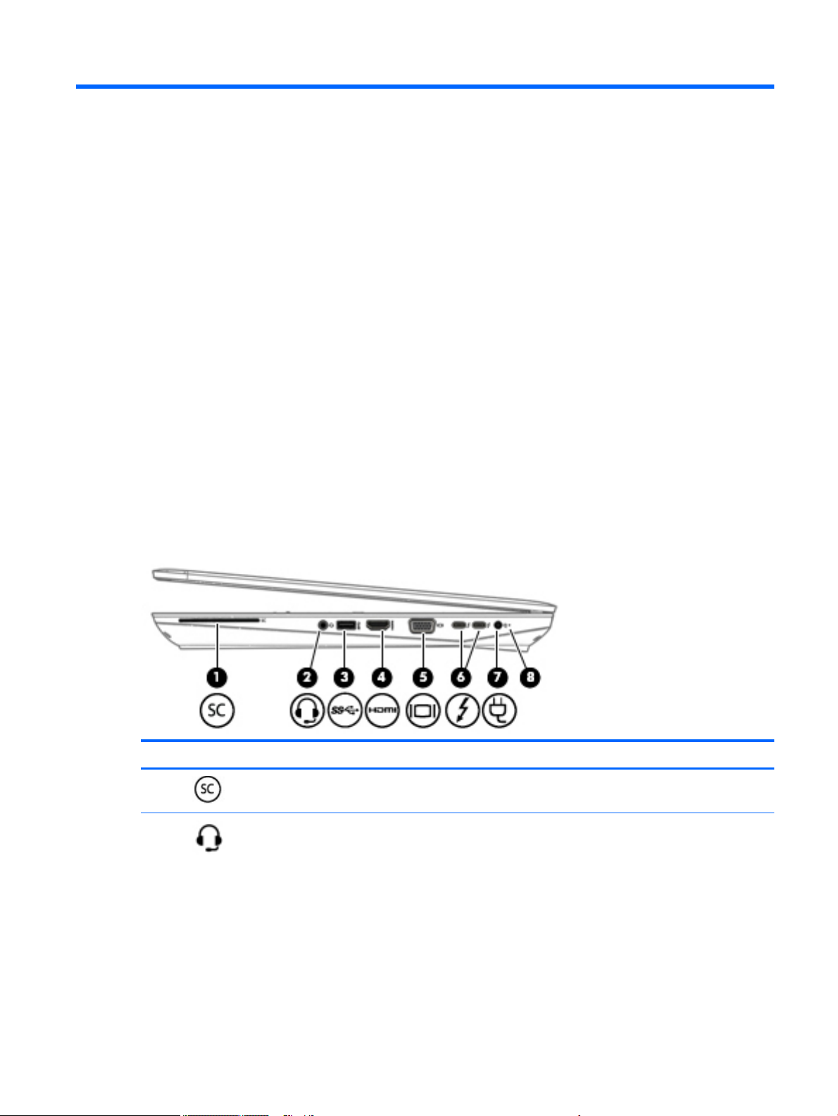
Right
Component Description
(1) Smart card reader Supports optional Smart cards.
(2) Audio-out (headphone)/Audio-in
(microphone) combo jack
Connects optional powered stereo speakers, headphones, earbuds, a
headset, or a television audio cable. Also connects an optional headset
microphone. This jack does not support optional standalone
microphones.
Locating hardware 7
Page 20
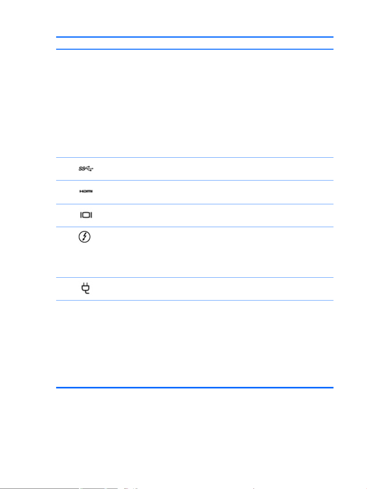
Component Description
WARNING! To reduce the risk of personal injury, adjust the volume
before putting on headphones, earbuds, or a headset. For additional
safety information, refer to the Regulatory, Safety, and Environmental
Notices.
To access this guide:
1. Type support in the taskbar search box, and then select the HP
Support Assistant app.
‒ or –
Click the question mark icon in the taskbar.
2. Select My PC, select the Specications tab, and then select User
Guides.
NOTE: When a device is connected to the jack, the computer speakers
are disabled.
(3) USB 3.0 port Connects an optional USB device, such as a keyboard, mouse, external
drive, printer, scanner or USB hub.
(4) HDMI port Connects an optional video or audio device, such as a high-denition
television, any compatible digital or audio component, or a high-speed
High Denition Multimedia Interface (HDMI) device.
(5) External monitor port Connects an external VGA monitor or projector.
(6) USB Type-C (Thunderbolt-3-
enabled) ports (2)
(7) Power connector Connects an AC adapter.
(8) Battery light When AC power is connected:
Connect any USB device with a Type-C connector.
NOTE: USB Type-C ports charge products such as cell phones,
laptops, tablets, and MP3 players, even when the computer is o. Also,
some USB Type-C ports connect DisplayPort, VGA, HDMI,
ThunderboltTM, and other video devices to provide video output.
NOTE: Adapters (purchased separately) may be required.
●
White: The battery charge is greater than 90 percent.
●
Amber: The battery charge is from 0 to 90 percent.
●
O: The battery is not charging.
When AC power is disconnected (battery not charging):
●
Blinking amber: The battery has reached a low battery level.
When the battery has reached a critical battery level, the battery
light begins blinking rapidly.
●
O: The battery is not charging.
8 Chapter 2 External component identication
Page 21
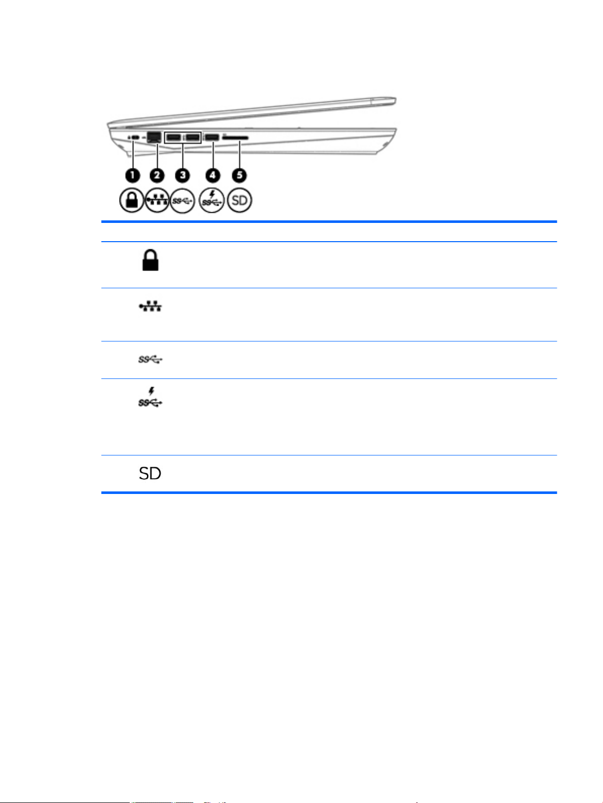
Left
Component Description
(1) Security cable slot Attaches an optional security cable to the computer.
NOTE: The security cable is designed to act as a deterrent, but it may
not prevent the computer from being mishandled or stolen.
(2) RJ-45 (network) jack/status lights Connects a network cable.
●
Green (left): The network is connected.
●
Amber (right): Activity is occurring on the network.
(3) USB 3.0 ports (2) Connect an optional USB device, such as a keyboard, mouse, external
drive, printer, scanner or USB hub.
(4) USB 3.0 charging (powered) port Connects an optional USB device, such as a keyboard, mouse, external
drive, printer, scanner or USB hub. Standard USB ports will not charge
all USB devices or will charge using a low current. Some USB devices
require power and require you to use a powered port.
NOTE: USB charging ports can also charge select models of cell
phones and MP3 players, even when the computer is o.
(5) Memory card reader Reads optional memory cards that store, manage, share, or access
information.
Left 9
Page 22
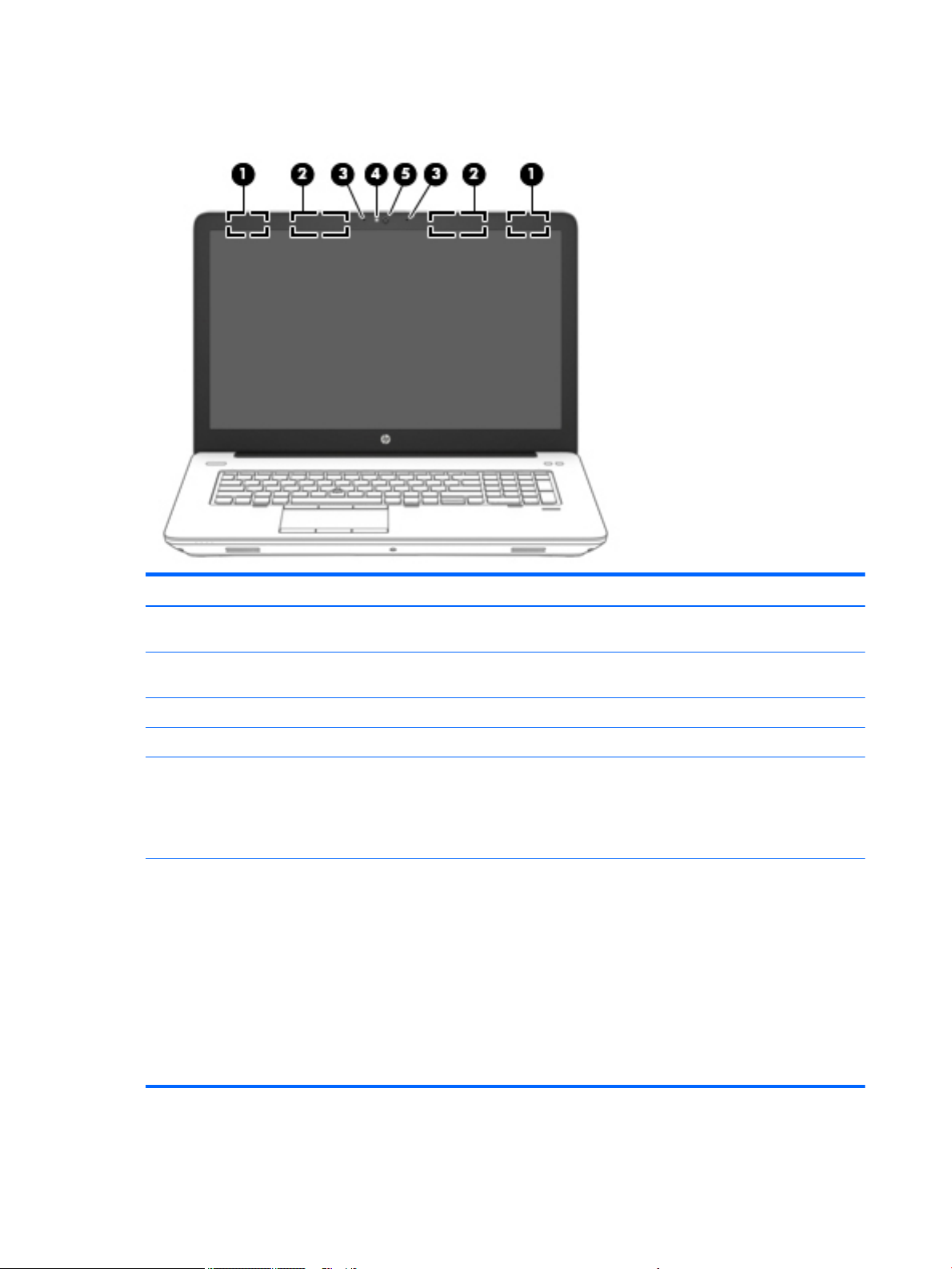
Display
Component Description
(1) WLAN antennas* Send and receive wireless signals to communicate with wireless local area networks
(WLANs). The internal antennas for your product will be located within this area.
(2) WWAN antennas (select products
only)*
(3) Internal microphones (2) Record sound.
(4) Webcam light (select products only) On: The webcam is in use.
(5) Webcam (select products only) Records video and captures photographs. Some models allow you to video
*The antennas are not visible from the outside of the computer. For optimal transmission, keep the areas immediately around the
antennas free from obstructions.
For wireless regulatory notices, see the section of the Regulatory, Safety, and Environmental Notices that applies to your country or
region.
To access this guide:
1. Type support in the taskbar search box, and then select the HP Support Assistant app.
‒ or –
Click the question mark icon in the taskbar.
2. Select My PC, select the Specications tab, and then select User Guides.
Send and receive wireless signals to communicate with wireless wide area networks
(WWANs). The internal antennas for your product will be located within this area.
conference and chat online using streaming video.
To use the webcam:
▲ Type camera in the taskbar search box, and then select Camera.
10 Chapter 2 External component identication
Page 23
Top
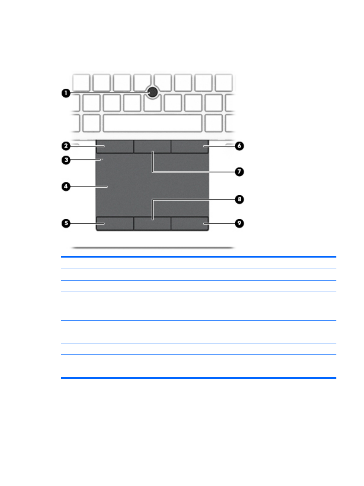
TouchPad
Component Description
(1) Pointing stick Moves the pointer and selects or activates items on the screen.
(2) Left pointing stick button Functions like the left button on an external mouse.
(3) TouchPad on/o button Turns the TouchPad on and o.
(4) TouchPad zone Reads your nger gestures to move the pointer or activate items on
the screen.
(5) Left TouchPad button Functions like the left button on an external mouse.
(6) Right pointing stick button Functions like the right button on an external mouse.
(7) Center pointing stick button Functions like the center button on an external mouse.
(8) Center TouchPad button Functions like the center button on an external mouse.
(9) Right TouchPad button Functions like the right button on an external mouse.
Top 11
Page 24
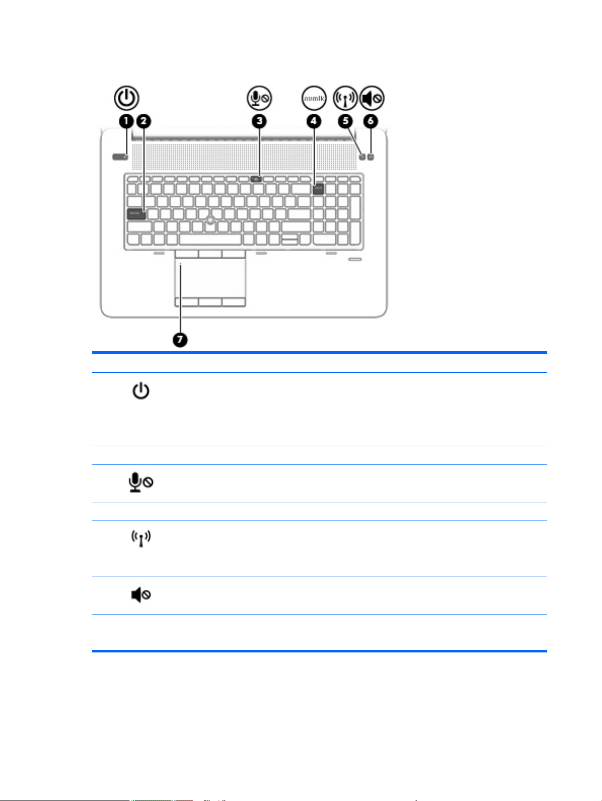
Lights
Component Description
(1) Power light
(2) Caps lock light On: Caps lock is on, which switches the key input to all capital letters.
(3) Microphone mute light
(4) Num lock light On: Num lock is on.
(5) Wireless light On: An integrated wireless device, such as a wireless local area network (WLAN)
(6) Mute light
(7) TouchPad light
●
On: The computer is on.
●
Blinking: The computer is in the Sleep state, a power-saving state. The
computer shuts o power to the display and other unneeded components.
●
O: The computer is o or in Hibernation. Hibernation is a power-saving
state that uses the least amount of power.
●
Amber: microphone sound is o.
●
O: microphone sound is on.
device and/or a Bluetooth® device, is on.
NOTE: On some models, the wireless light is amber when all wireless devices
are o.
●
Amber: Computer sound is o.
●
O: Computer sound is on.
●
On: The TouchPad is o.
●
O: The TouchPad is on.
12 Chapter 2 External component identication
Page 25
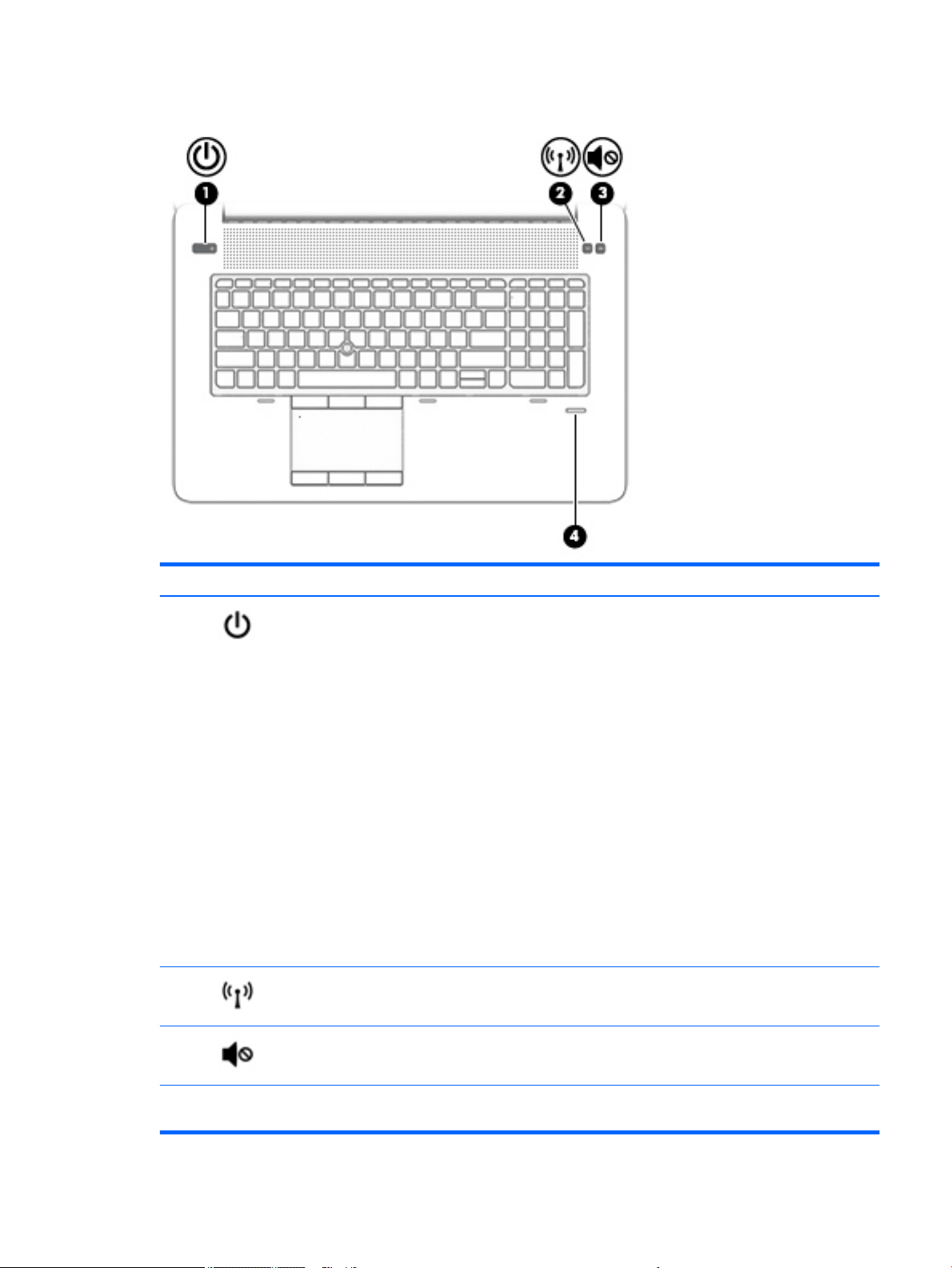
Buttons and ngerprint reader
Component Description
(1) Power button
(2) Wireless button Turns the wireless feature on or o but does not establish a wireless connection.
(3) Volume mute button Mutes and restores speaker sound.
●
When the computer is o, press the button to turn on the computer.
●
When the computer is on, press the button briey to initiate Sleep.
●
When the computer is in the Sleep state, press the button briey to exit
Sleep.
●
When the computer is in Hibernation, press the button briey to exit
Hibernation.
CAUTION: Pressing and holding down the power button results in the loss of
unsaved information.
If the computer has stopped responding and shutdown procedures are
ineective, press and hold the power button for at least 5 seconds to turn o the
computer.
To learn more about your power settings, see your power options.
▲ Type power in the taskbar search box, and then select Power and sleep
settings.
‒ or –
Right-click the Start button, and then select Power Options.
A wireless network must be set up before a wireless connection is possible.
(4) Fingerprint reader (select
products only)
Allows a ngerprint logon to Windows®, instead of a password logon.
Top 13
Page 26
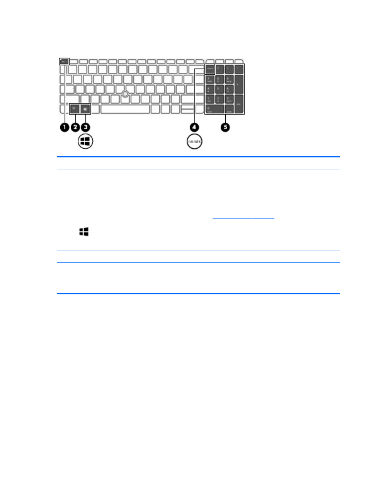
Special function keys
Component Description
(1) esc key Displays system information when pressed in combination with
(2) fn key Executes frequently used system functions when pressed in
the fn key.
combination with a function key, the num lock key, or the esc
key.
See Using the hot keys on page 15.
(3) Windows key Opens the Start menu.
NOTE: Pressing the Windows key again will close the Start
menu.
(4) num lock key Turns the numeric keypad on and o.
(5) Integrated numeric keypad A separate keypad to the right of the alphabet keyboard that
enables you to add, subtract, and perform other numeric tasks.
When num lock is on, the integrated keypad can be used like an
external numeric keypad.
14 Chapter 2 External component identication
Page 27
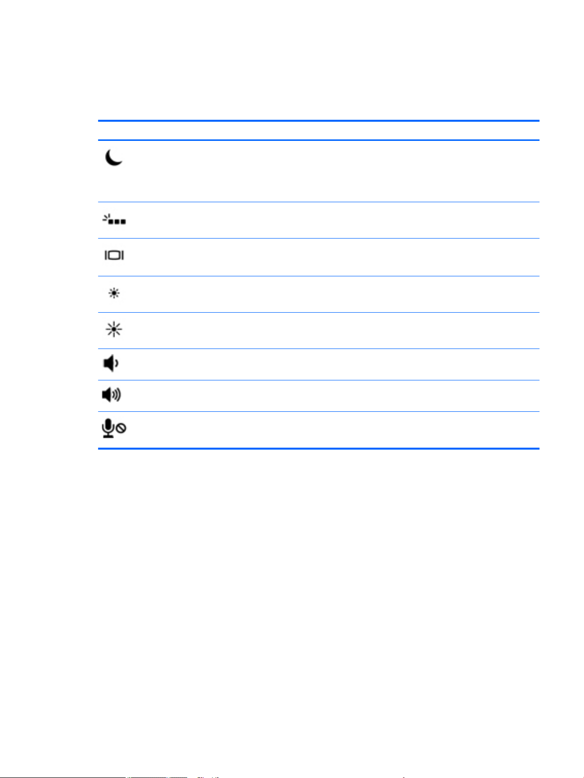
Using the hot keys
To use a hot key:
▲
Press the fn key, and then press the correct function key represented by the icons below.
Press fn+function key Description
Initiates Sleep, which saves your information in system memory. The display and other system components
turn o and power is conserved.
To exit Sleep, briey press the power button.
CAUTION: To reduce the risk of information loss, save your work before initiating Sleep.
Turns the keyboard backlight o or on.
NOTE: To conserve battery power, turn o this feature.
Switches the screen image between display devices connected to the system. For example, if a monitor is
connected to the computer, repeatedly pressing this key alternates the screen image from the computer
display to the monitor display to a simultaneous display on both the computer and the monitor.
Decreases the screen brightness incrementally as long as you hold down the key.
Increases the screen brightness incrementally as long as you hold down the key.
Decreases speaker volume incrementally while you hold down the key.
Increases speaker volume incrementally while you hold down the key.
Mutes the microphone.
Top 15
Page 28
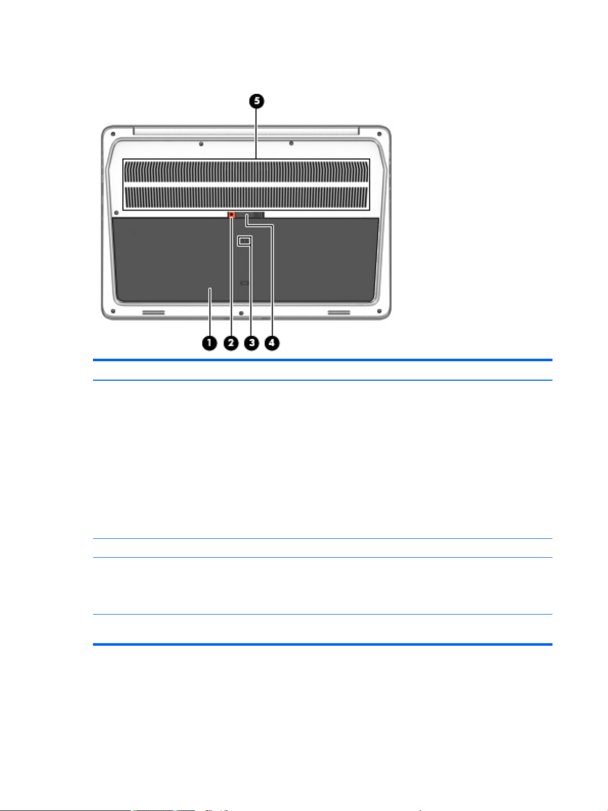
Bottom
Component Description
(1) Service door Provides access to the hard drive bay, the WLAN module slot, the
WWAN module slot, and the memory module slots.
CAUTION: To prevent an unresponsive system, replace the wireless
module only with a wireless module authorized for use in the computer
by the governmental agency that regulates wireless devices in your
country or region. If you replace the module and then receive a
warning message, remove the module to restore computer
functionality, and then contact support.
▲ Type support in the taskbar search box, and then select the HP
Support Assistant app.
- or -
Click the question mark icon in the taskbar.
(2) Service door release screws Releases the service door.
(3) Vents Enable airow to cool internal components.
NOTE: The computer fan starts up automatically to cool internal
components and prevent overheating. It is normal for the internal fan
to cycle on and o during routine operation.
(4) Spill drain Allows spilled liquids, such as sodas or coee, to drain out of the
computer.
16 Chapter 2 External component identication
Page 29
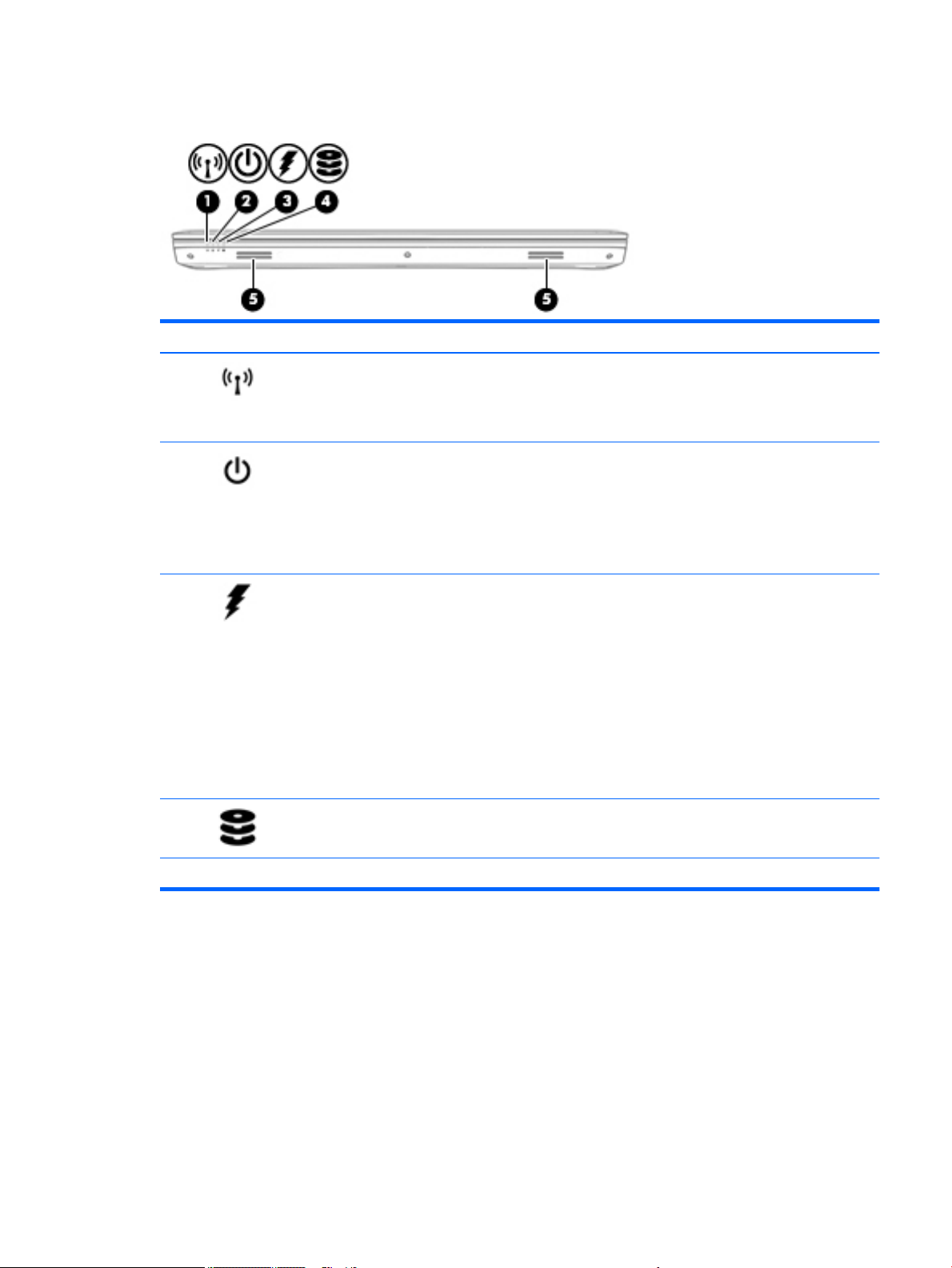
Front
Component Description
(1) Wireless light On: An integrated wireless device, such as a wireless local area
network (WLAN) device and/or a Bluetooth® device, is on.
NOTE: On some models, the wireless light is amber when all wireless
devices are o.
(2) Power light
(3) Battery light When AC power is connected:
(4) Drive light
(5) Speakers Produce sound.
●
On: The computer is on.
●
Blinking: The computer is in the Sleep state, a power-saving
state. The computer shuts o power to the display and other
unneeded components.
●
O: The computer is o or in Hibernation. Hibernation is a powersaving state that uses the least amount of power.
●
White: The battery charge is greater than 90 percent.
●
Amber: The battery charge is from 0 to 90 percent.
●
O: The battery is not charging.
When AC power is disconnected (battery not charging):
●
Blinking amber: The battery has reached a low battery level.
When the battery has reached a critical battery level, the battery
light begins blinking rapidly.
●
O: The battery is not charging.
●
Blinking white: The hard drive is being accessed.
●
Amber: HP 3D DriveGuard has temporarily parked the hard drive.
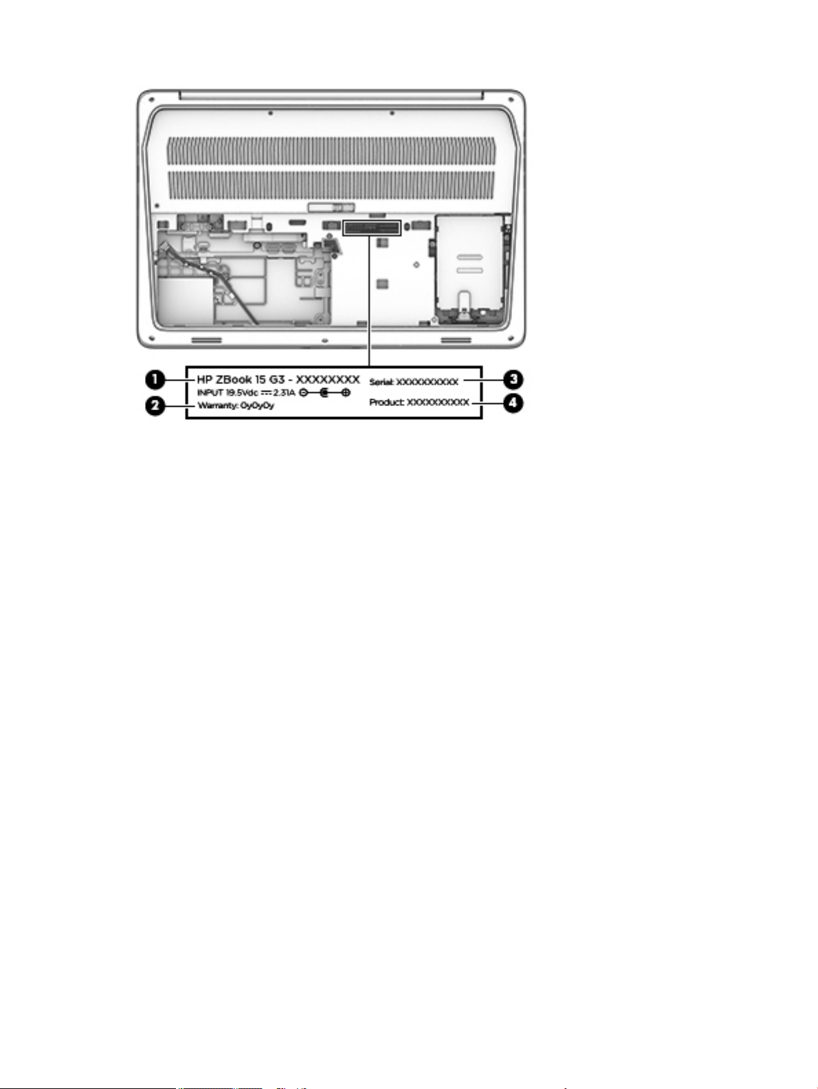
Locating system information
Important system information is located on the bottom edge of the tablet or on the keyboard base. You may
need the information when travelling internationally or when you contact support:
(1): Serial number
(2): Product number
(3): Model number
(4): Warranty period
Front 17
Page 30
Using Windows, briey press the fn+esc key combination to display the System Information screen, which
provides the product name and serial number of your computer, as well as information about the memory,
processor, BIOS, and keyboard.
18 Chapter 2 External component identication
Page 31

3 Illustrated parts catalog
Computer major components
NOTE: HP continually improves and changes product parts. For complete and current information on
supported parts for your computer, go to http://partsurfer.hp.com, select your country or region, and then
follow the on-screen instructions.
NOTE: Details about your computer, including model, serial number, product key, and length of warranty,
are on the service tag at the bottom of your computer. See Locating system information on page 17 for
details.
Computer major components 19
Page 32
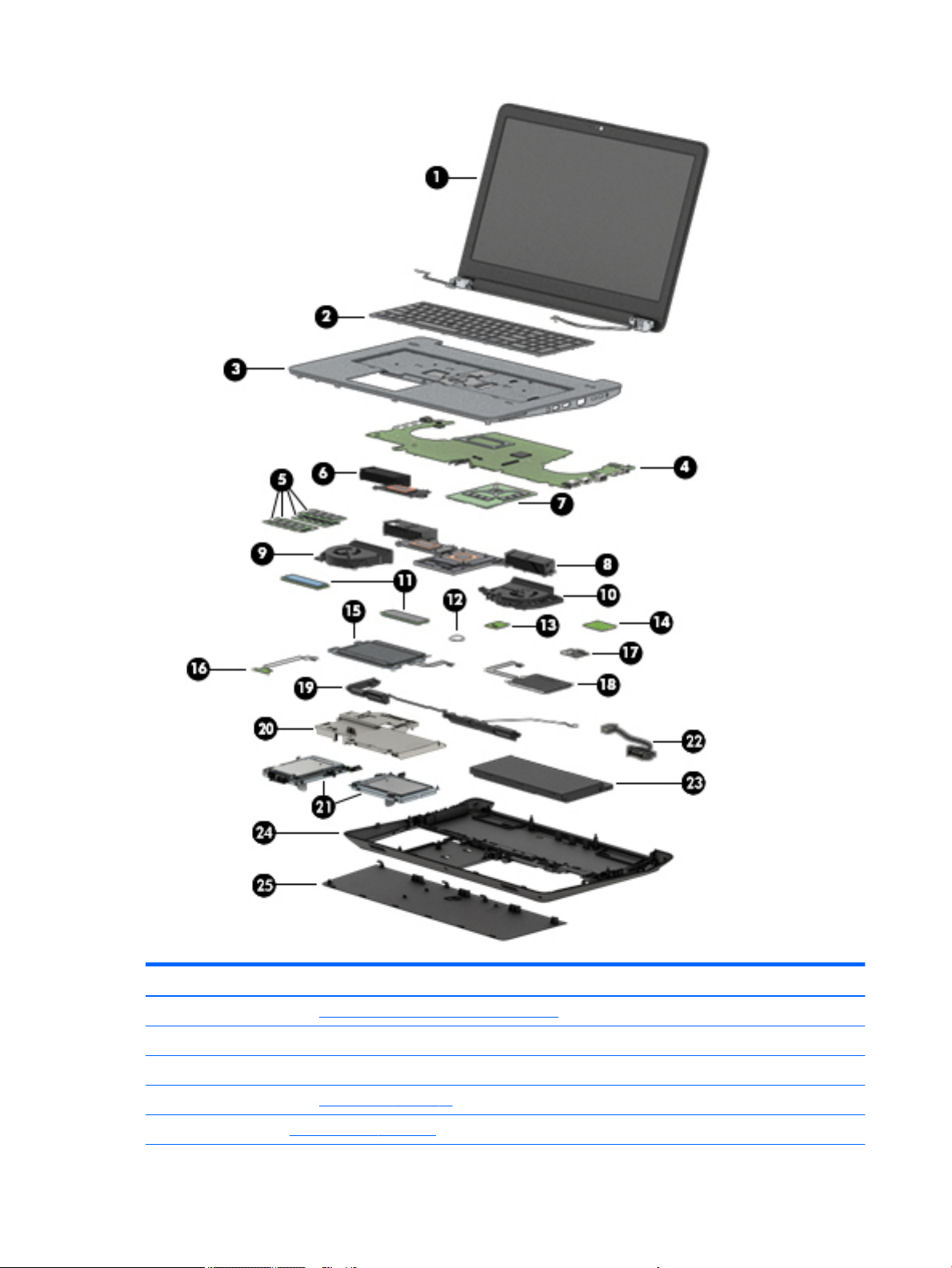
Item Component Spare part number
(1) Display panel (See Display assembly subcomponents on page 22)
(2) Keyboard (See ) 848311-001
(3) Top cover 929011-001
(4) System board (see System board on page 64)
(5) Memory (See Memory module on page 44)
20 Chapter 3 Illustrated parts catalog
Page 33

Item Component Spare part number
(6) Heat sink for models with UMA graphics (see Heat sink on page 56)
(7) Graphics board (see Discrete graphics board on page 59)
(8) Heat sink (see Heat sink on page 56)
(9) Fan (see Fan on page 54)
(10) Fan (see Fan on page 54)
(11) Solid-state drives (2) (see Solid-state drives (M.2) on page 38)
(12) RTC battery 922847-001
(13) WLAN module (see WLAN module on page 40)
(14) WWAN module (see WWAN module on page 42)
(15) TouchPad (includes cable) 929011-001
(16) LED board (includes cable)
(17) Fingerprint reader (includes cable 850116-001
(18) Smart card reader (includes cable
(19) Speaker Kit (includes cable 848361-001
(20) Internal frame 906119-001
(21) Hard drives (2) (see Hard drive(s) and internal frame on page 33)
(22) Battery cable 907156-001
(23) Battery 852711-850
(24) Base enclosure 906112-001
(25) Service door 906121-001
Computer major components 21
Page 34
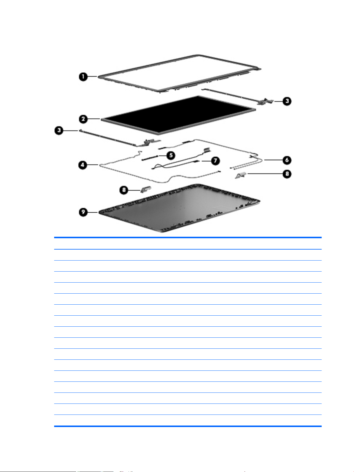
Display assembly subcomponents
Item Component Spare part number
(1) Bezel
LCD bezel with magnet FHD 17 848368-001
LCD bezel with camera 850119-001
(2) Panel
LCD HU 17.3 FHD UWVA AG with camera and touch screen 921322-001
Display HU DRM3 UHD UWVA 921323-001
Display HU DRM3 UHD UWVA f/CAM 921324-001
Raw panel 17.3 FHDAGWLEDUWVA300eDP Flat AK 819347-002
Raw panel 17.3 HD+AGWLEDSVA 220eDP Flat AK 819348-002
(3) Hinge 906120-001
(4) Display cable 848379-001
(5) Webcam 819336-006
(6) WWAN antenna 848347-001
(7) WLAN antenna 848346-001
(8) Hinge covers (included with hinges)
(9) Back cover 926796-001
22 Chapter 3 Illustrated parts catalog
Page 35

Miscellaneous parts
Component Spare part number
HP USB-C to DisplayPort adapter 831753-001
200W PFC SMART 4.5mm SLIM 3P AC adapter 835888-001
Cable kit 848372-001
HP ZBook Thunderbolt 3 power cable A 855116-001
HP Business Top Load Case 718550-001
HP Executive Slim Top Load Case 838256-001
HP Elite USB-C Docking Station 844549-001
HP USB Laser Mouse 674318-001
HP Comfort Grip Wireless Mouse 691922-001
HP Ultrathin Bluetooth Mouse 811730-001
Microphone board 854110-001
Power cord
For use in Argentina 401328-001
For use in Australia and New Zealand 100661-001
For use in Brazil 438723-001
For use in Denmark 130627-008
For use in Europe 100614-009
For use in India 403440-001
For use in Israel 398062-001
For use in Italy 109197-008
For use in Japan 139867-004
For use in the People’s Republic of China 286496-001
For use in South Africa 187487-005
For use in South Korea 231216-001
For use in Switzerland 150304-008
For use in Thailand 285052-001
For use in Taiwan 393312-001
For use in the United Kingdom and Singapore 100613-008
AC power cord, unshielded 121565-001
Screw kit 922848-001
Miscellaneous parts 23
Page 36
4 Removal and replacement procedures
preliminary requirements
Tools required
You will need the following tools to complete the removal and replacement procedures:
●
Flat-bladed screwdriver
●
Magnetic screwdriver
●
Phillips P0 and Torx8 T8 screwdrivers
Service considerations
The following sections include some of the considerations that you must keep in mind during disassembly
and assembly procedures.
NOTE: As you remove each subassembly from the computer, place the subassembly (and all accompanying
screws) away from the work area to prevent damage.
Plastic parts
CAUTION: Using excessive force during disassembly and reassembly can damage plastic parts. Use care
when handling the plastic
24 Chapter 4 Removal and replacement procedures preliminary requirements
Page 37

Cables and connectors
CAUTION: When servicing the computer, be sure that cables are placed in their proper locations during the
reassembly process. Improper cable placement can damage the computer.
Cables must be handled with extreme care to avoid damage. Apply only the tension required to unseat or seat
the cables during removal and insertion. Handle cables by the connector whenever possible. In all cases, avoid
bending, twisting, or tearing cables. Be sure that cables are routed in such a way that they cannot be caught
or snagged by parts being removed or replaced. Handle ex cables with extreme care; these cables tear
easily.
Drive handling
CAUTION: Drives are fragile components that must be handled with care. To prevent damage to the
computer, damage to a drive, or loss of information, observe these precautions:
Before removing or inserting a hard drive, shut down the computer. If you are unsure whether the computer is
o or in Hibernation, turn the computer on, and then shut it down through the operating system.
Before handling a drive, be sure that you are discharged of static electricity. While handling a drive, avoid
touching the connector.
Before removing an optical drive, be sure that a disc is not in the drive and be sure that the optical drive tray is
closed.
Handle drives on surfaces covered with at least one inch of shock-proof foam.
Avoid dropping drives from any height onto any surface.
After removing a hard drive or an optical drive, place it in a static-proof bag.
Avoid exposing an internal hard drive to products that have magnetic elds, such as monitors or speakers.
Avoid exposing a drive to temperature extremes or liquids.
If a drive must be mailed, place the drive in a bubble pack mailer or other suitable form of protective
packaging and label the package “FRAGILE.”
Service considerations 25
Page 38
Grounding guidelines
Electrostatic discharge damage
Electronic components are sensitive to electrostatic discharge (ESD). Circuitry design and structure determine
the degree of sensitivity. Networks built into many integrated circuits provide some protection, but in many
cases, ESD contains enough power to alter device parameters or melt silicon junctions.
A discharge of static electricity from a nger or other conductor can destroy static-sensitive devices or
microcircuitry. Even if the spark is neither felt nor heard, damage may have occurred.
An electronic device exposed to ESD may not be aected at all and can work perfectly throughout a normal
cycle. Or the device may function normally for a while, then degrade in the internal layers, reducing its life
expectancy.
CAUTION: To prevent damage to the computer when you are removing or installing internal components,
observe these precautions:
Keep components in their electrostatic-safe containers until you are ready to install them.
Before touching an electronic component, discharge static electricity by using the guidelines described in this
section.
Avoid touching pins, leads, and circuitry. Handle electronic components as little as possible.
If you remove a component, place it in an electrostatic-safe container.
The following table shows how humidity aects the electrostatic voltage levels generated by dierent
activities.
CAUTION: A product can be degraded by as little as 700 V.
Typical electrostatic voltage levels
Relative humidity
Event 10% 40% 55%
Walking across carpet 35,000 V 15,000 V 7,500 V
Walking across vinyl oor 12,000 V 5,000 V 3,000 V
Motions of bench worker 6,000 V 800 V 400 V
Removing DIPS from plastic tube 2,000 V 700 V 400 V
Removing DIPS from vinyl tray 11,500 V 4,000 V 2,000 V
Removing DIPS from plastic foam 14,500 V 5,000 V 3,500 V
Removing bubble pack from PCB 26,500 V 20,000 V 7,000 V
Packing PCBs in foam-lined box 21,000 V 11,000 V 5,000 V
26 Chapter 4 Removal and replacement procedures preliminary requirements
Page 39

Packaging and transporting guidelines
Follow these grounding guidelines when packaging and transporting equipment:
●
To avoid hand contact, transport products in static-safe tubes, bags, or boxes.
●
Protect ESD-sensitive parts and assemblies with conductive or approved containers or packaging.
●
Keep ESD-sensitive parts in their containers until the parts arrive at static-free workstations.
●
Place items on a grounded surface before removing items from their containers.
●
Always be properly grounded when touching a component or assembly.
●
Store reusable ESD-sensitive parts from assemblies in protective packaging or nonconductive foam.
●
Use transporters and conveyors made of antistatic belts and roller bushings. Be sure that mechanized
equipment used for moving materials is wired to ground and that proper materials are selected to avoid
static charging. When grounding is not possible, use an ionizer to dissipate electric charges.
Workstation guidelines
Follow these grounding workstation guidelines:
●
Cover the workstation with approved static-shielding material.
●
Use a wrist strap connected to a properly grounded work surface and use properly grounded tools and
equipment.
●
Use conductive eld service tools, such as cutters, screwdrivers, and vacuums.
●
When xtures must directly contact dissipative surfaces, use xtures made only of static safe materials.
●
Keep the work area free of nonconductive materials, such as ordinary plastic assembly aids and plastic
foam.
●
Handle ESD-sensitive components, parts, and assemblies by the case or PCM laminate. Handle these
items only at static-free workstations.
●
Avoid contact with pins, leads, or circuitry.
●
Turn o power and input signals before inserting or removing connectors or test equipment.
Grounding guidelines 27
Page 40

Equipment guidelines
Grounding equipment must include either a wrist strap or a foot strap at a grounded workstation.
●
When seated, wear a wrist strap connected to a grounded system. Wrist straps are exible straps with a
minimum of one megohm ±10% resistance in the ground cords. To provide proper ground, wear a strap
snugly against the skin at all times. On grounded mats with banana-plug connectors, use alligator clips
to connect a wrist strap.
●
When standing, use foot straps and a grounded oor mat. Foot straps (heel, toe, or boot straps) can be
used at standing workstations and are compatible with most types of shoes or boots. On conductive
oors or dissipative oor mats, use foot straps on both feet with a minimum of one megohm resistance
between the operator and ground. To be eective, the conductive equipment must be worn in contact
with the skin.
The following grounding equipment is recommended to prevent electrostatic damage:
●
Antistatic tape
●
Antistatic smocks, aprons, and sleeve protectors
●
Conductive bins and other assembly or soldering aids
●
Nonconductive foam
●
Conductive tabletop workstations with ground cords of one megohm resistance
●
Static-dissipative tables or oor mats with hard ties to the ground
●
Field service kits
●
Static awareness labels
●
Material-handling packages
●
Nonconductive plastic bags, tubes, or boxes
●
Metal tote boxes
●
Electrostatic voltage levels and protective materials
The following table lists the shielding protection provided by antistatic bags and oor mats.
Material Use Voltage protection level
Antistatic plastics Bags 1,500 V
Carbon-loaded plastic Floor mats 7,500 V
Metallized laminate Floor mats 5,000 V
28 Chapter 4 Removal and replacement procedures preliminary requirements
Page 41
5 Removal and replacement procedures for
Customer Self-Repair parts
NOTE: The Customer Self-Repair program is not available in all locations. Installing a part not supported by
the Customer Self-Repair program may void your warranty. Check your warranty to determine if Customer
Self-Repair is supported in your location.
NOTE: HP continually improves and changes product parts. For complete and current information on
supported parts for your computer, go to http://partsurfer.hp.com, select your country or region, and then
follow the on-screen instructions.
Component replacement procedures
NOTE: Please read and follow the procedures described here to access and replace Customer Self-Repair
parts successfully.
NOTE: Details about your computer, including model, serial number, product key, and length of warranty,
are on the service tag on the bottom of your computer. See Locating system information on page 17
for details.
This chapter provides removal and replacement procedures for Customer Self-Repair parts.
There are as many as 30 screws that must be removed, replaced, and/or loosened when servicing Customer
Self-Repair parts. Make special note of each screw size and location during removal and replacement.
Component replacement procedures 29
Page 42
Service door
Description Spare part number
Service door 906121-001
Before removing the service door, follow these steps:
1. Turn o the computer. If you are unsure whether the computer is o or in Hibernation, turn the
2. Disconnect the power from the computer by unplugging the power cord from the computer.
3. Disconnect all external devices from the computer.
Remove the service door:
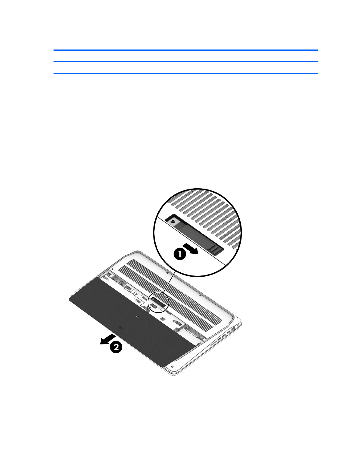
1. Position the computer upside down on a at surface.
2. Slide the latch (1) to release the service door.
3. Remove the service door (2).
computer on, and then shut it down through the operating system.
Reverse this procedure to install the service door.
30 Chapter 5 Removal and replacement procedures for Customer Self-Repair parts
Page 43
Battery
Description Spare part number
6 cell HP Long Life Prismatic 96 Whr (4.21 Ahr) Li-ion battery 852711-850
Battery cable 907156-001
Before removing the battery, follow these steps:
1. Turn o the computer. If you are unsure whether the computer is o or in Hibernation, turn the
computer on, and then shut it down through the operating system.
2. Disconnect the power from the computer by unplugging the power cord from the computer.
3. Disconnect all external devices from the computer.
4. Remove the service door (see Service door on page 30).
Remove the battery:
WARNING! To reduce potential safety issues, use only the user-replaceable battery provided with the
computer, a replacement battery provided by HP, or a compatible battery purchased from HP.
CAUTION: Removing a user-replaceable battery that is the sole power source for the computer can cause
loss of information. To prevent loss of information, save your work or shut down the computer through
Windows before removing the battery.
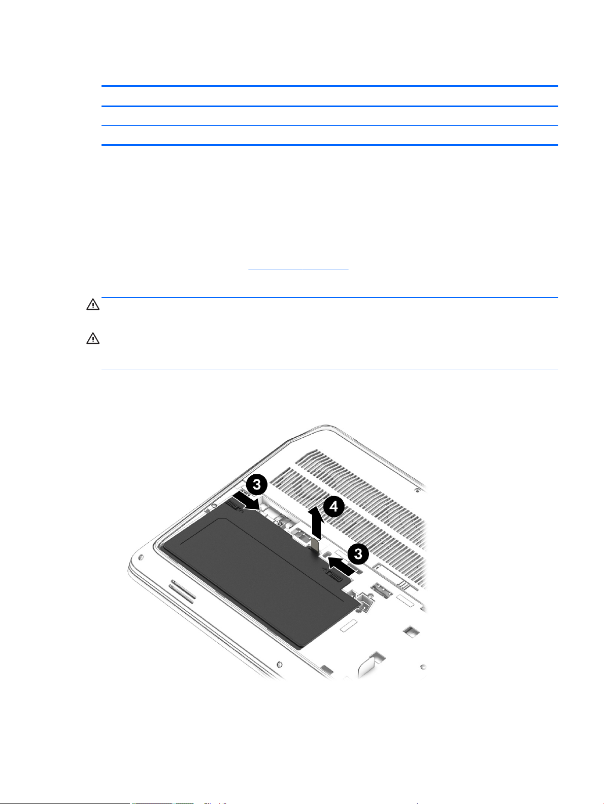
1. Remove the three Phillips screws (3) that secure the battery to the computer.
2. Pull the battery tab (4) to remove the battery from the computer.
Component replacement procedures 31
Page 44
Remove the battery cable:
▲
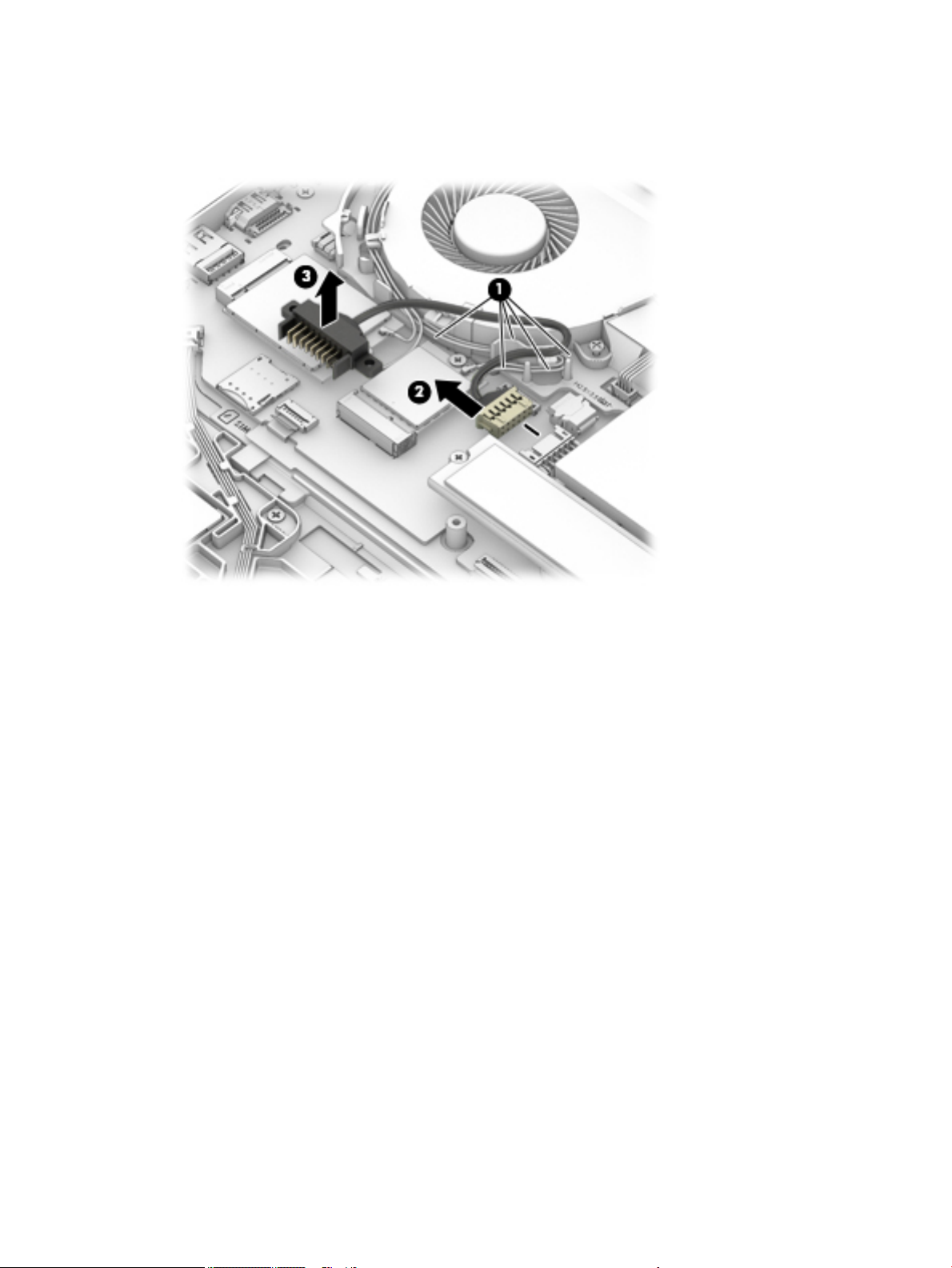
Release the battery cable from the guides (1), disconnect the battery cable from the system board (2),
and then remove the cable (3).
Reverse this procedure to install the battery cable and the battery.
32 Chapter 5 Removal and replacement procedures for Customer Self-Repair parts
Page 45
Base enclosure
Description Spare part number
Base enclosure 906112-001
Before removing the base enclosure, follow these steps:
1. Turn o the computer. If you are unsure whether the computer is o or in Hibernation, turn the
computer on, and then shut it down through the operating system.
2. Disconnect the power from the computer by unplugging the power cord from the computer.
3. Disconnect all external devices from the computer.
4. Remove the following components:
a. Service door (see Service door on page 30).
b. Battery (see Battery on page 31).
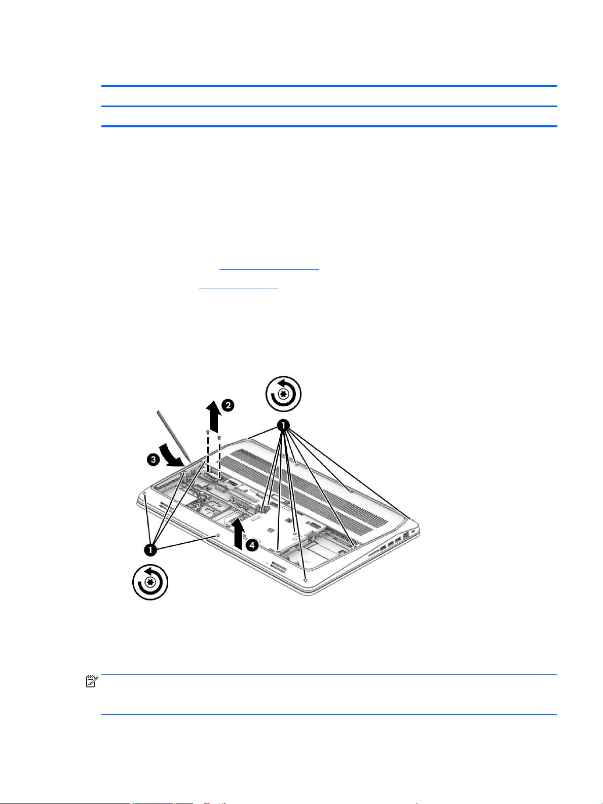
Remove the base enclosure:
1. Loosen 14 Torx screws(1), and then remove 2 Phillips screws(2) from the base enclosure.
2. Using a plastic tool (3), loosen the base enclosure, and then remove it from the computer (4).
Reverse this procedure to install the base enclosure.
Hard drive(s) and internal frame
NOTE: The hard drive spare kit does not include the hard drive bracket or hard drive cable. The hard drive
bracket, screws, and hard drive cable are included in the Hard Drive Hardware Kit, spare part number
848351-001.
Component replacement procedures 33
Page 46

Description Spare part number
500 GB 7200 RPM RAW 7mm 703267-002
500 GB 5400 RPM SATA RAW Hybrid 8 GB cache 7 mm 732000-002
1 TB 7200 RPM SATA RAW 9.5 mm 766644-002
500 GB 7200 RPM SATA FIPS RAW 7 mm 820572-002
500 GB 7200 RPM SATA RAW SED 7 mm 820573-002
HDD Hardware Kit 906117-001
Internal frame 906119-001
HDD connector bracket 907157-001
HDD board 929012-001
Before removing the hard drive, follow these steps:
1. Shut down the computer. If you are unsure whether the computer is o or in Hibernation, turn the
computer on, and then shut it down through the operating system.
2. Disconnect the power from the computer by unplugging the power cord from the computer.
3. Disconnect all external devices from the computer.
4. Remove the following components:
a. Service door (see Service door on page 30).
b. Battery (see Battery on page 31).
c. Base enclosure (see Base enclosure on page 33).
Remove the hard drive:
1. Disconnect the hard drive connector (1).
2. Remove 2 Phillips screws (2) from the hard drive bracket.
3. Loosen the four captive screws (3) that secure the hard drive to the bottom cover.
34 Chapter 5 Removal and replacement procedures for Customer Self-Repair parts
Page 47
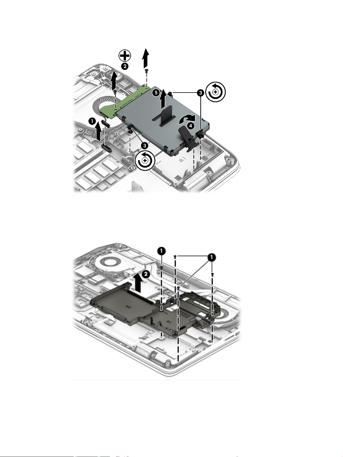
4. Lift the tab (4), and remove the primary hard drive (5).
5. If it is necessary to replace the hard drive connector adapter on the primary hard drive, slide the adapter
(1) o of the front end of the hard drive, and then remove the cable from the adapter (2).
Remove the internal frame:
▲
Remove 3 screws (1), and then remove the internal frame (2).
Remove the secondary hard drive (select products only):
1. Disconnect the hard drive connector (1).
2. Remove 2 Phillips screws (2) from the hard drive bracket.
Component replacement procedures 35
Page 48
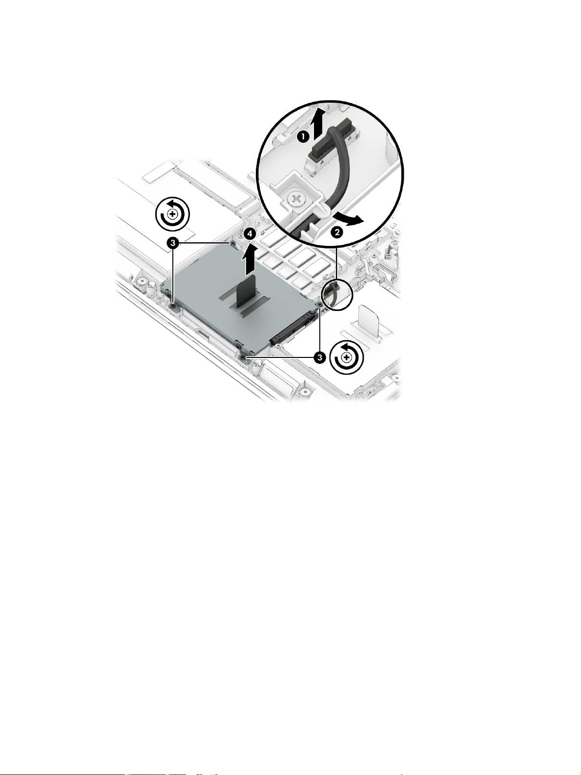
3. Loosen the four captive screws (3) that secure the hard drive to the bottom cover.
4. Lift the tab (4), and remove the primary hard drive (5).
Remove the hard drive bracket(s):
1. If it is necessary to replace the primary hard drive bracket, remove 4 screws (2) from the hard drive, and
then lift the bracket straight up (3) to remove the bracket from the hard drive.
36 Chapter 5 Removal and replacement procedures for Customer Self-Repair parts
Page 49
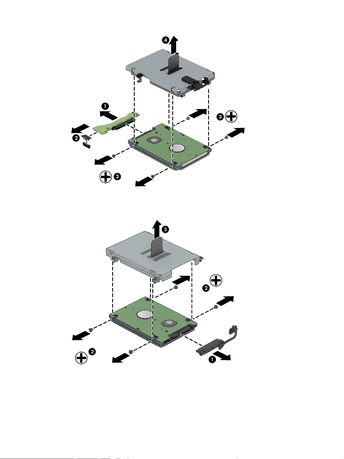
2. If it is necessary to replace the secondary hard drive bracket, remove the connector from the bracket (1),
remove 4 screws (2) from the hard drive, and then lift the bracket straight up (3) to remove the bracket
from the hard drive.
Reverse this procedure to reassemble and install the hard drive(s) and the internal frame.
Component replacement procedures 37
Page 50

Solid-state drives (M.2)
Description Spare part number
256 GB, Turbo Drive, G2, MLC 921331-001
512 GB, M2 SATA-3, FIPS, TLC 921332-001
256 GB, SATA-3 self-encrypting drive (SED), Opal 2, TLC 921333-001
256 GB, Turbo Drive, G2, TLC 921334-001
512 GB, Turbo Drive, G2, MLC 921335-001
512 GB, Turbo Drive, G2, self-encrypting drive (SED), Opal 2, TLC 921336-001
1 TB, Turbo Drive, G2, MLC 921337-001
256 GB, SATA, TLC 921338-001
1 TB, SATA-3, TLC 926788-001
Before removing the SSD, follow these steps:
1. Turn o the computer. If you are unsure whether the computer is o or in Hibernation, turn the
computer on, and then shut it down through the operating system.
2. Disconnect the power from the computer by unplugging the power cord from the computer.
3. Disconnect all external devices from the computer.
4. Remove the following components:
a. Service door (see Service door on page 30).
b. Battery (see Battery on page 31).
c. Base enclosure (see Base enclosure on page 33).
d. Hard drive(s) and internal frame (see Hard drive(s) and internal frame on page 33).
Remove the SSD:
NOTE: The secondary SSD is only available if a primary SSD is installed.
1. Remove the Phillips screw (1) that secures the solid-state drive to the system board.
2. Remove the SSD (2) by pulling the drive away from the slot at an angle.
38 Chapter 5 Removal and replacement procedures for Customer Self-Repair parts
Page 51
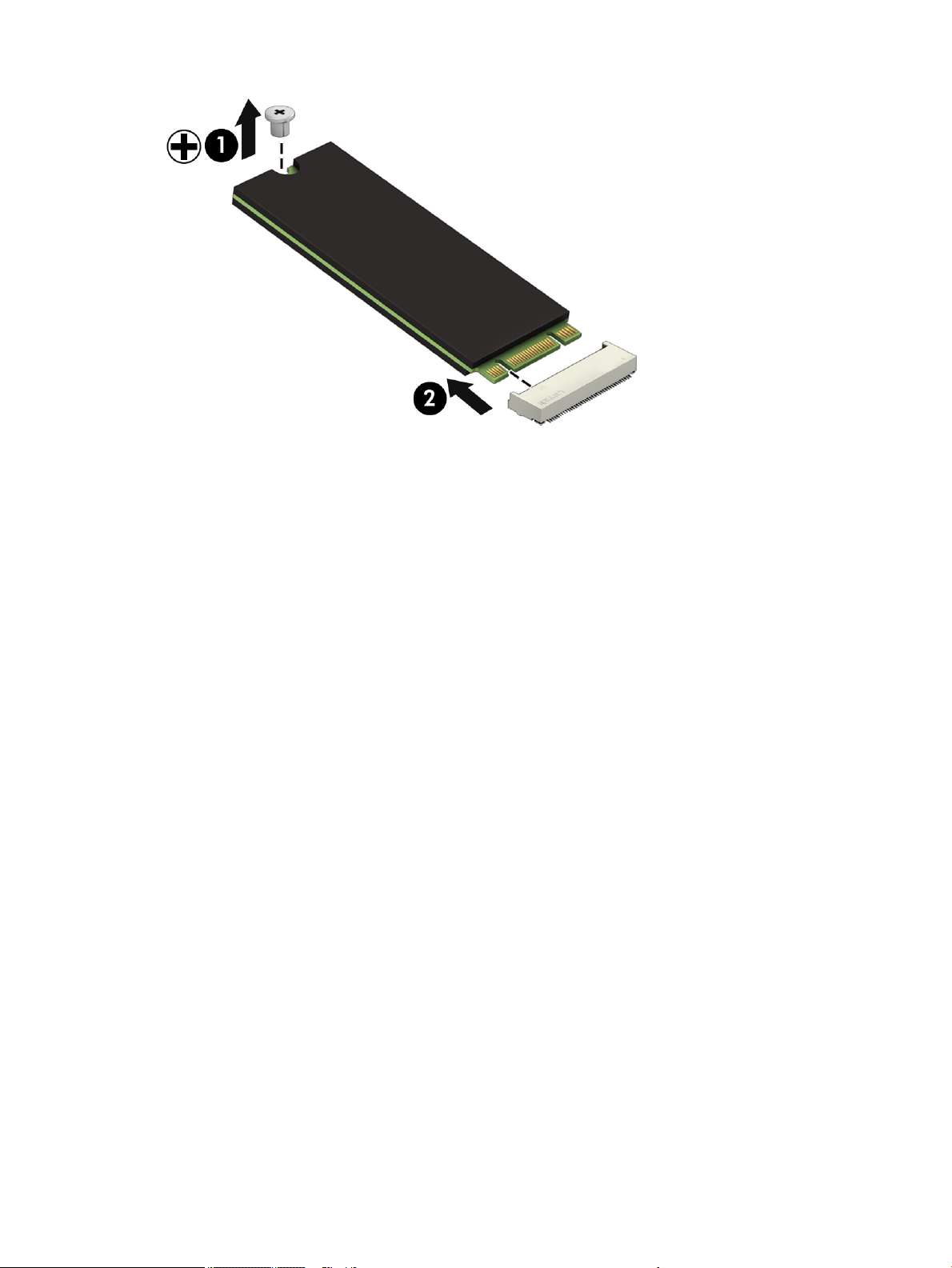
Reverse this procedure to install the solid-state drive.
Component replacement procedures 39
Page 52

WLAN module
Description Spare part number
Intel Dual Band Wireless-AC 8265 3rd Gen Intel 802.11ac, Dual Band, 2x2 Wi-Fi + Bluetooth 4.2 910264-852
Intel Dual Band Wireless-AC 8265 3rd Gen Intel 802.11ac, Dual Band, 2x2 Wi-Fi + Bluetooth 4.2 (nonvPro)
918855-852
CAUTION: To prevent an unresponsive system, replace the wireless module only with a wireless module
authorized for use in the computer by the governmental agency that regulates wireless devices in your
country or region. If you replace the module and then receive a warning message, remove the module to
restore device functionality, and then contact technical support.
Before removing the WLAN module, follow these steps:
1. Turn o the computer. If you are unsure whether the computer is o or in Hibernation, turn the
computer on, and then shut it down through the operating system.
2. Disconnect the power from the computer by unplugging the power cord from the computer.
3. Disconnect all external devices from the computer.
4. Remove the following components:
a. Service door (see Service door on page 30).
b. Battery (see Battery on page 31).
c. Base enclosure (see Base enclosure on page 33).
d. Hard drive(s) and internal frame (see Hard drive(s) and internal frame on page 33).
e. Solid-state drive(s) (see Solid-state drives (M.2) on page 38).
Remove the WLAN module:
1. Disconnect the WLAN antenna cables (1) from the terminals on the WLAN module.
NOTE: The WLAN antenna cable labeled “1” connects to the WLAN module “Main” terminal labeled “1”.
The WLAN antenna cable labeled “2” connects to the WLAN module “Aux” terminal labeled “2”.
2. Remove the Phillips screw (2) that secures the WLAN module to the system board. (The WLAN module
tilts up.)
40 Chapter 5 Removal and replacement procedures for Customer Self-Repair parts
Page 53
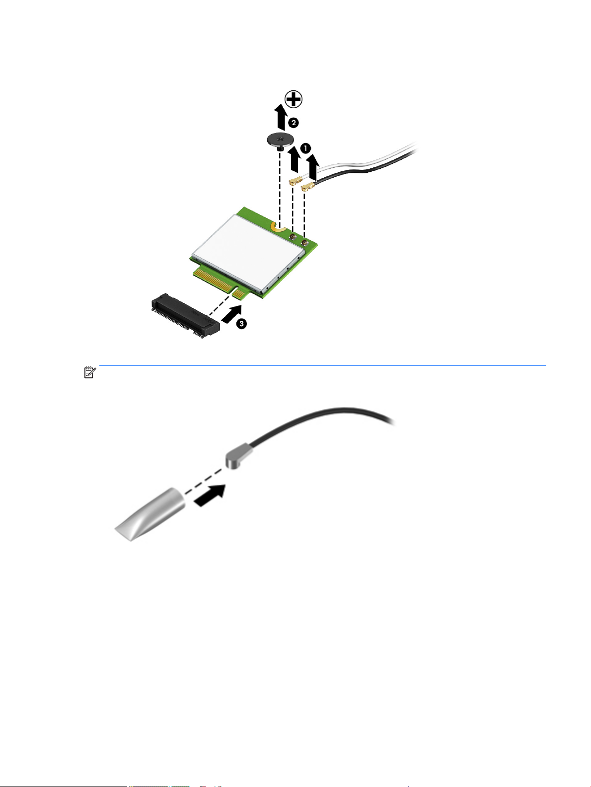
3. Remove the WLAN module (3) by pulling the module away from the slot at an angle.
NOTE: If the WLAN antenna cables are not connected to the terminals on the WLAN module, protective
sleeves should be installed on the antenna connectors, as shown in the following illustration.
Reverse this procedure to install the WLAN module.
Component replacement procedures 41
Page 54

WWAN module
NOTE: The WWAN module and the WLAN module are not interchangeable.
Description Spare part number
T77W595 LTE M.2 with GPS 800870-001
HSPA+M.2 918670-852
ME906S LTE with GPS M.2 918671-852
Before removing the WWAN module, follow these steps:
1. Turn o the computer. If you are unsure whether the computer is o or in Hibernation, turn
the computer on, and then shut it down through the operating system.
2. Disconnect the power from the computer by unplugging the power cord from the computer.
3. Disconnect all external devices from the computer.
4. Remove the following components:
a. Service door (see Service door on page 30).
b. Battery (see Battery on page 31).
c. Base enclosure (see Base enclosure on page 33).
d. Hard drive(s) and internal frame (see Hard drive(s) and internal frame on page 33).
e. Solid-state drive(s) (see Solid-state drives (M.2) on page 38).
f. WLAN module (see WLAN module on page 40).
Remove the WWAN module:
1. Disconnect the WWAN antenna cables (1) from the terminals on the WWAN module.
NOTE: The red WWAN antenna cable is connected to the WWAN module “Main” terminal. The blue
WWAN antenna cable is connected to the WWAN module “Aux” terminal.
2. Remove the Phillips screw (2) that secures the WWAN module to the base enclosure.
42 Chapter 5 Removal and replacement procedures for Customer Self-Repair parts
Page 55
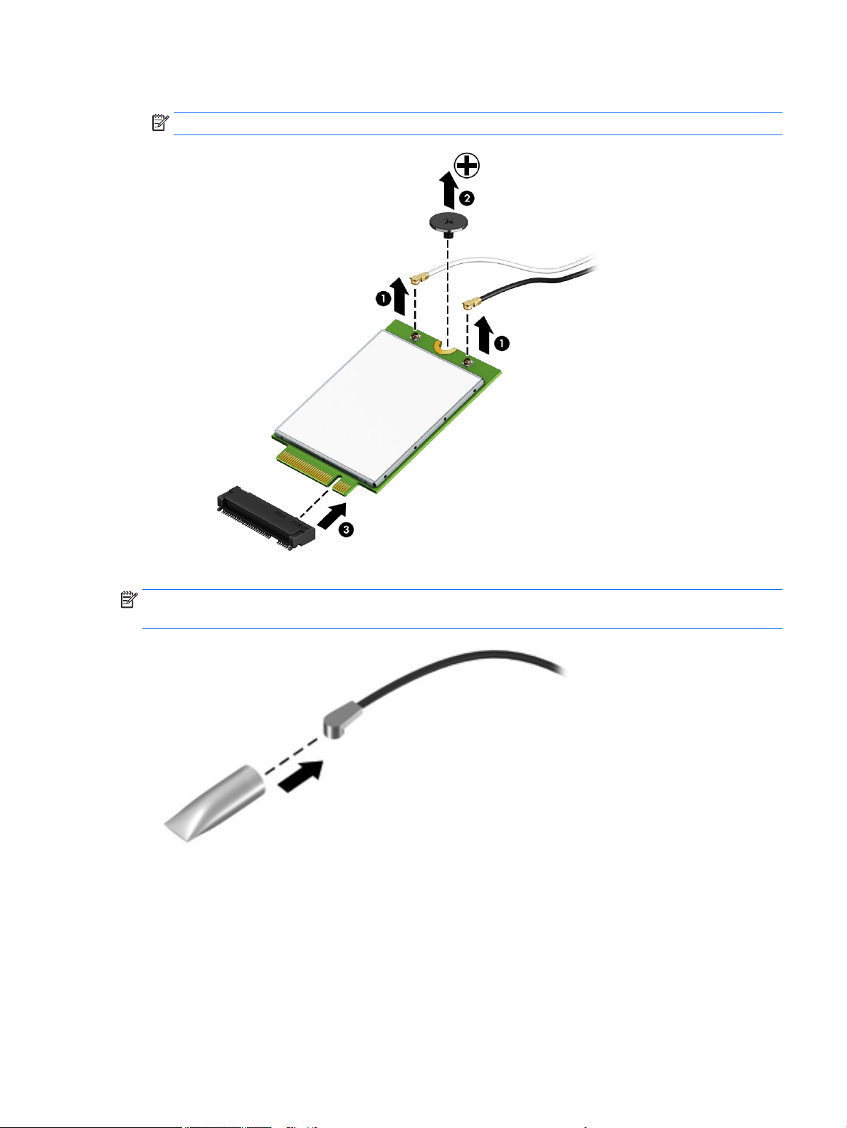
3. Remove the WWAN module (3) by pulling the module away from the slot.
NOTE: WWAN modules are designed with a notch to prevent incorrect insertion.
NOTE: If the WWAN antennas are not connected to the terminals on the WWAN module, the protective
sleeves must be installed on the antenna connectors, as shown in the following illustration.
Reverse this procedure to install the WWAN module.
Component replacement procedures 43
Page 56
Memory module
Description Spare part number
DDR4-2400:
16 GB 865396-852
8 GB 862398-852
4 GB 862397-852
ECC DDR4-2133:
16 GB, ECC 835886-001
8 GB, ECC 835887-001
Update BIOS before adding memory modules
Before adding new memory, be sure to update the computer to the latest BIOS.
CAUTION: Failure to update the computer to the latest BIOS prior to installing new memory may result in
various system problems.
To update BIOS:
1. Navigate to http:\\www.hp.com.
2. Select Support > Support & drivers.
3. In the Enter my HP model number box, type the computer model information, and then select Find my
product.
-or-
Select Identify now.
4. Select the link for the computer model.
5. Select the language and the operating system.
6. Under the downloads heading, select the BIOS link.
7. Select the link for the most recent BIOS.
8. Select the Download button, and then follow the on-screen instructions.
Before removing a memory module, follow these steps:
1. Turn o the computer. If you are unsure whether the computer is o or in Hibernation, turn the
computer on, and then shut it down through the operating system.
2. Disconnect the power from the computer by unplugging the power cord from the computer.
3. Disconnect all external devices from the computer.
4. Remove the following components:
a. Service door (see Service door on page 30).
b. Battery (see Battery on page 31).
c. Base enclosure (see Base enclosure on page 33).
44 Chapter 5 Removal and replacement procedures for Customer Self-Repair parts
Page 57
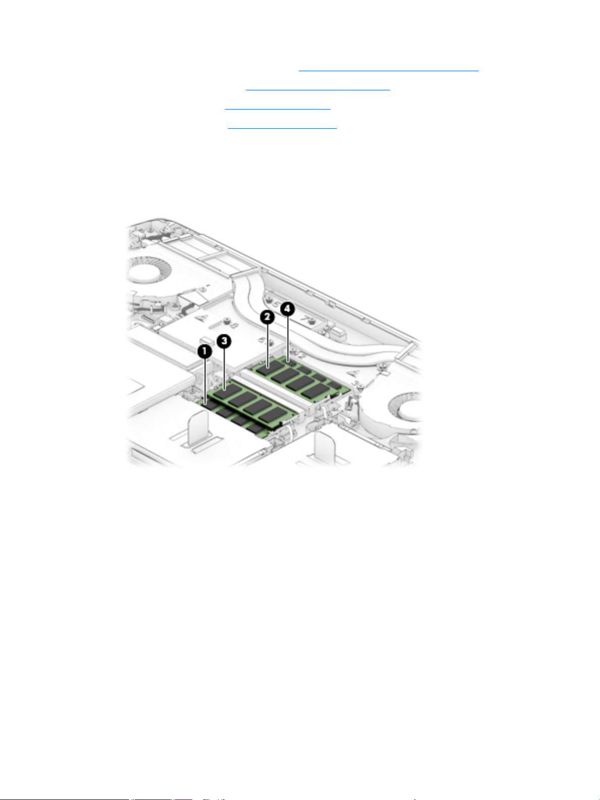
d. Hard drive(s) and internal frame (see Hard drive(s) and internal frame on page 33).
e. Solid-state drive(s) (see Solid-state drives (M.2) on page 38).
f. WLAN module (see WLAN module on page 40).
g. WWAN module (see WWAN module on page 42).
Remove the memory module:
1. Identify the location of the memory module slots (1) – (4). The system memory must be installed in the
order shown. The BIOS checks for this and will not boot if the memory is not installed into the correct
slots. The BIOS will display a message in POST notifying the user that the system memory is not
installed in the proper order.
2. Spread the retaining tabs (1) on each side of the memory module slot to release the memory module.
(The memory module tilts up.)
Component replacement procedures 45
Page 58
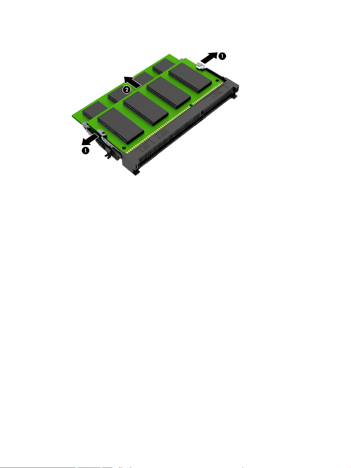
3. Remove the memory module (2) by pulling the module away from the slot at an angle.
Reverse this procedure to install a memory module.
46 Chapter 5 Removal and replacement procedures for Customer Self-Repair parts
Page 59
6 Removal and replacement procedures for
authorized service provider parts
CAUTION: Components described in this chapter should be accessed only by an authorized service provider.
Users who access these parts can damage the computer or void the warranty.
NOTE: HP continually improves and changes product parts. For complete and current information on
supported parts for your computer, go to http://partsurfer.hp.com, select your country or region, and then
follow the on-screen instructions.
Component replacement procedures
There are as many as 88 screws that must be removed, replaced, and/or loosened when servicing the parts
described in this chapter. Make special note of each screw size and location during removal and replacement.
Component replacement procedures 47
Page 60
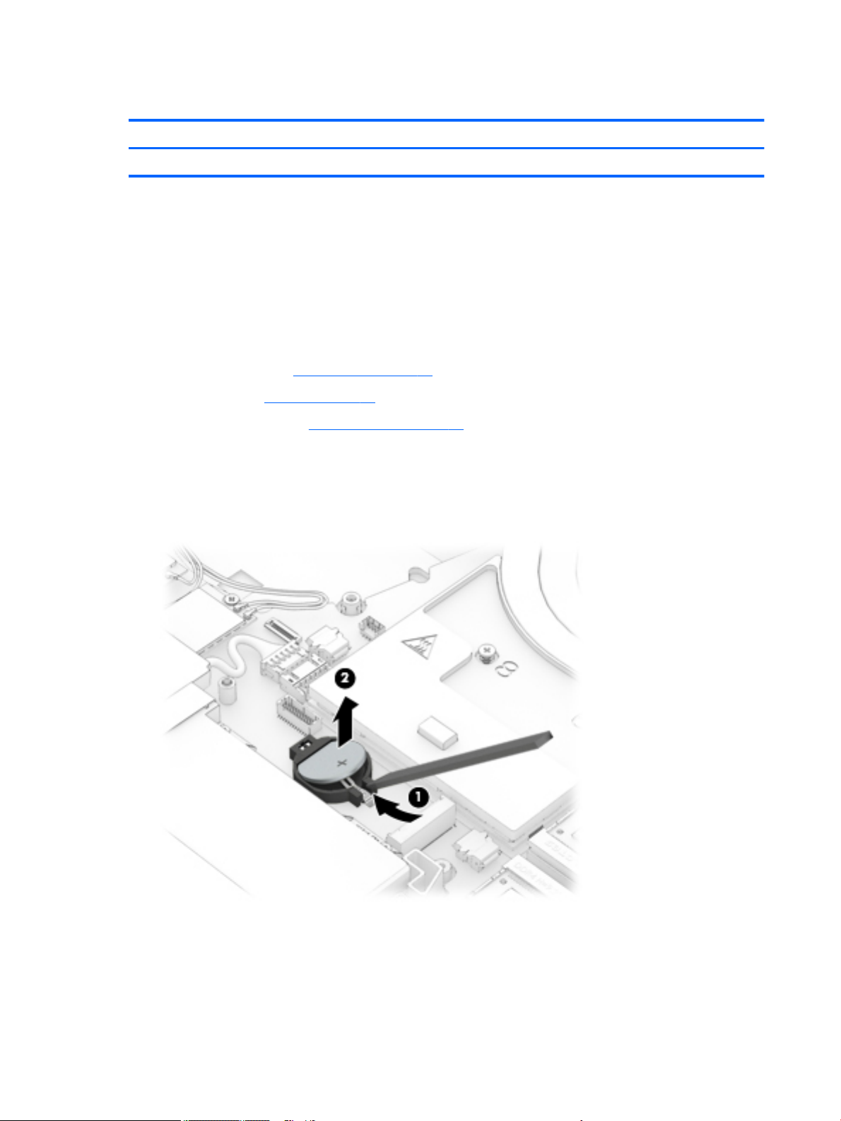
RTC battery
Description Spare part number
RTC battery (includes cable and double-sided adhesive) 922847-001
Before removing the RTC battery, follow these steps:
1. Turn o the computer. If you are unsure whether the computer is o or in Hibernation, turn the
2. Disconnect the power from the computer by unplugging the power cord from the computer.
3. Disconnect all external devices from the computer.
4. Remove the following components:
Remove the RTC battery:
1. Disconnect the RTC battery cable (1) from the system board.
2. Using a plastic tool, detach the RTC battery (2) from the base enclosure and remove it from the
computer on, and then shut it down through the operating system.
a. Service door (see Service door on page 30).
b. Battery (see Battery on page 31).
c. Base enclosure (see Base enclosure on page 33).
computer. (The RTC battery is attached to the base enclosure with double-sided adhesive.)
Reverse this procedure to install the RTC battery.
48 Chapter 6 Removal and replacement procedures for authorized service provider parts
Page 61
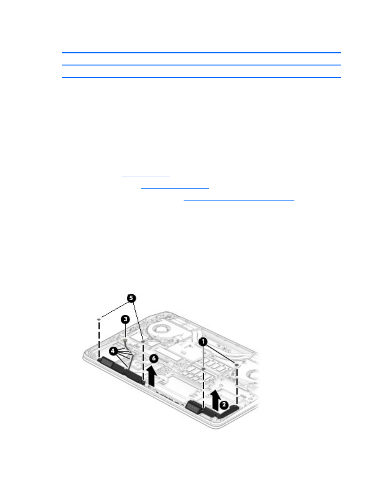
Speakers
Before removing the speakers, follow these steps:
1. Turn o the computer. If you are unsure whether the computer is o or in Hibernation, turn the
2. Disconnect the power from the computer by unplugging the power cord from the computer.
3. Disconnect all external devices from the computer.
4. Remove the following components:
Remove the speakers:
1. Remove the two Phillips screws (1) that secure the right speaker to the computer.
Description Spare part number
Speakers (includes cable) 848361-001
computer on, and then shut it down through the operating system.
a. Service door (see Service door on page 30).
b. Battery (see Battery on page 31).
c. Base enclosure (see Base enclosure on page 33).
d. Hard drive(s) and internal frame (see Hard drive(s) and internal frame on page 33).
2. Remove the right speaker (2).
3. Disconnect the speaker cable from the system board (3), and then release the cable from the guides (4)
securing it to the computer.
4. Remove the two Phillips screws (5) that secure the left speaker to the computer.
5. Remove the left speaker (6).
Reverse this procedure to install the speakers.
Component replacement procedures 49
Page 62
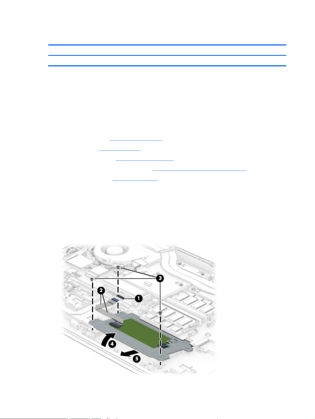
TouchPad
Before removing the TouchPad, follow these steps:
1. Turn o the computer. If you are unsure whether the computer is o or in Hibernation, turn the
2. Disconnect the power from the computer by unplugging the power cord from the computer.
3. Disconnect all external devices from the computer.
4. Remove the following components:
Remove the TouchPad:
Description Spare part number
TouchPad module (includes cable) 924810-001
computer on, and then shut it down through the operating system.
a. Service door (see Service door on page 30).
b. Battery (see Battery on page 31).
c. Base enclosure (see Base enclosure on page 33).
d. Hard drive(s) and internal frame (see Hard drive(s) and internal frame on page 33).
e. Right speaker (see Speakers on page 49).
1. Open the zero insertion force (ZIF) connector (1) on the system board to release the TouchPad ribbon
cable.
2. Carefully remove the ribbon cable (2) from the adhesive securing it to the computer.
3. Remove the three Phillips screws (3) that secure the TouchPad.
4. Lift the TouchPad (4) up at an angle, and then remove the TouchPad (5) from the computer.
50 Chapter 6 Removal and replacement procedures for authorized service provider parts
Page 63
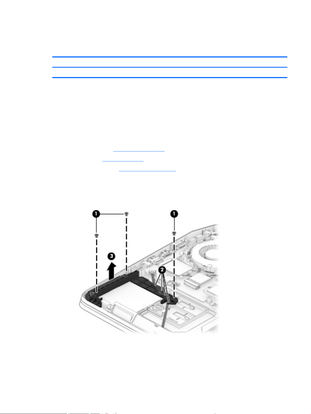
Reverse this procedure to install the TouchPad.
Smart card reader and frame
Description Spare part number
Smart card reader
Before removing the smart card reader, follow these steps:
1. Turn o the computer. If you are unsure whether the computer is o or in Hibernation, turn the
computer on, and then shut it down through the operating system.
2. Disconnect the power from the computer by unplugging the power cord from the computer.
3. Disconnect all external devices from the computer.
4. Remove the following components:
a. Service door (see Service door on page 30).
b. Battery (see Battery on page 31).
c. Base enclosure (see Base enclosure on page 33).
Remove the smart card reader:
1. Remove 3 Phillips screws (1), release the cable from the routing (2), and then lift the bracket to remove
it (3).
Component replacement procedures 51
Page 64
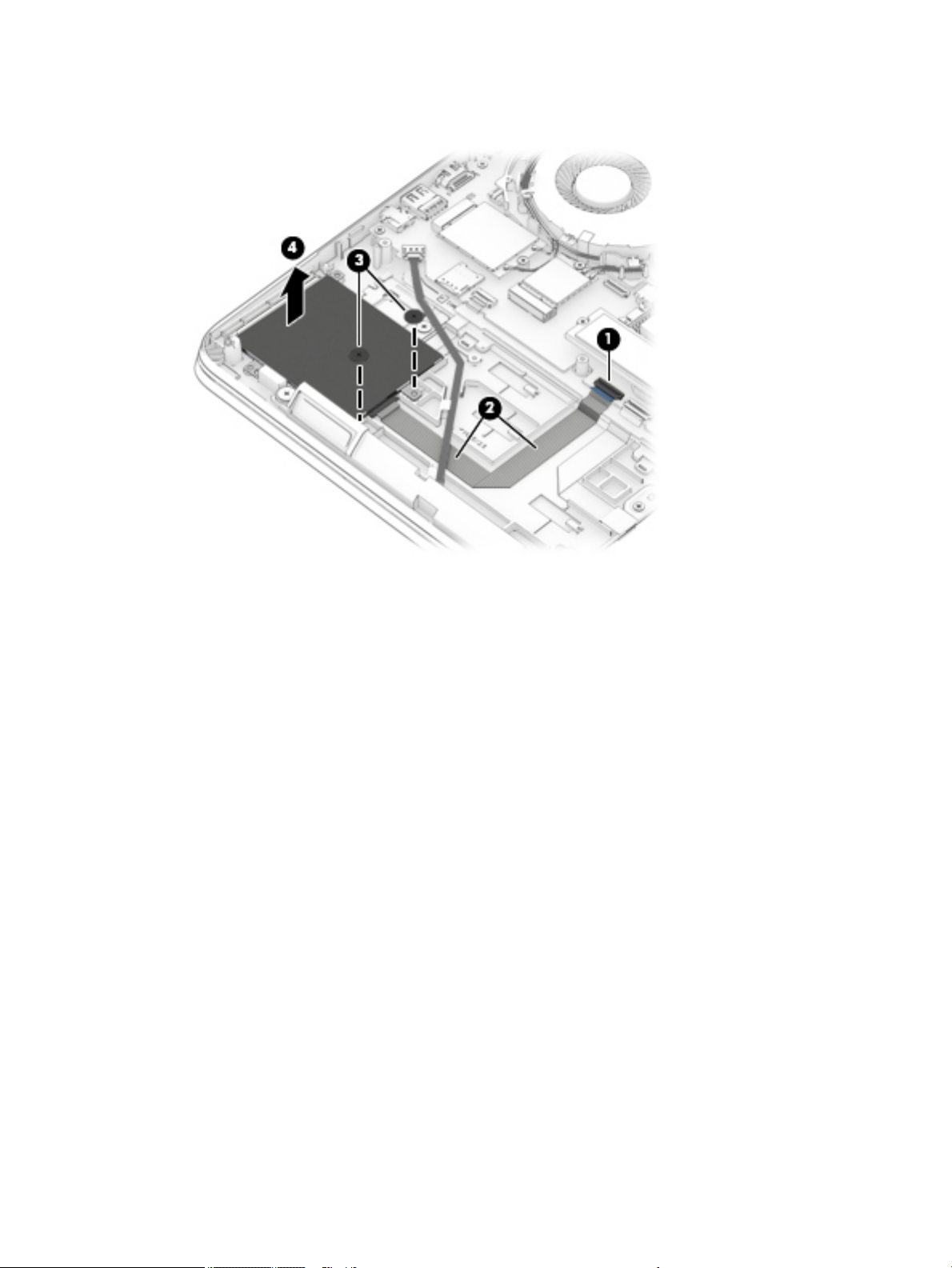
2. Disconnect the smart card reader cable from the system board (1), lift the cable (2), remove 2 Phillips
screws (3), and then lift the smart card reader to remove it (4).
Reverse this procedure to install the smart card reader.
52 Chapter 6 Removal and replacement procedures for authorized service provider parts
Page 65

Fingerprint reader board
Description Spare part number
Fingerprint reader board bracket (part of the bracket kit) 848360-001
Fingerprint reader board 850116-001
Before removing the ngerprint reader board, follow these steps:
1. Turn o the computer. If you are unsure whether the computer is o or in Hibernation, turn the
computer on, and then shut it down through the operating system.
2. Disconnect the power from the computer by unplugging the power cord from the computer.
3. Disconnect all external devices from the computer.
4. Remove the following components:
a. Service door (see Service door on page 30).
b. Battery (see Battery on page 31).
c. Base enclosure (see Base enclosure on page 33).
d. Hard drive(s) and internal frame (see Hard drive(s) and internal frame on page 33).
e. Smart card frame and smart card reader (see Smart card reader and frame on page 51).
Remove the ngerprint reader board:
1. Remove the Phillips screw (1) that secures the ngerprint reader board bracket to the computer.
2. Lift the bracket up (2) and then slide the bracket o the ngerprint reader (3).
3. Open the ZIF connector (4) on the system board to release the ngerprint reader cable.
4. Carefully lift the ribbon cable (5) to release it from adhesive securing it to the computer.
Component replacement procedures 53
Page 66
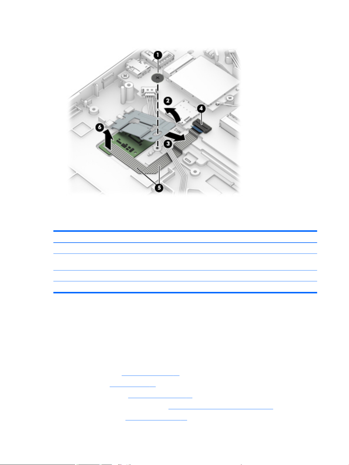
5. Release the ngerprint reader (6) from the double-sided tape and remove it from the computer.
Reverse this procedure to install the ngerprint reader board.
Fan
Description Spare part number
CPU fan (includes replacement thermal material) 848377-001
GPU Fan (includes replacement thermal material) (This fan is included as a blank for models with UMA
graphics memory.):
●
For use only with models with discrete graphics memory 848378-001
●
For models with UMA graphics memory 848376-001
Before removing the fans, follow these steps:
1. Turn o the computer. If you are unsure whether the computer is o or in Hibernation, turn the
computer on, and then shut it down through the operating system.
2. Disconnect the power from the computer by unplugging the power cord from the computer.
3. Disconnect all external devices from the computer.
4. Remove the following components:
a. Service door (see Service door on page 30).
b. Battery (see Battery on page 31).
c. Base enclosure (see Base enclosure on page 33).
d. Hard drive(s) and internal frame (see Hard drive(s) and internal frame on page 33).
e. WLAN module (see WLAN module on page 40).
54 Chapter 6 Removal and replacement procedures for authorized service provider parts
Page 67
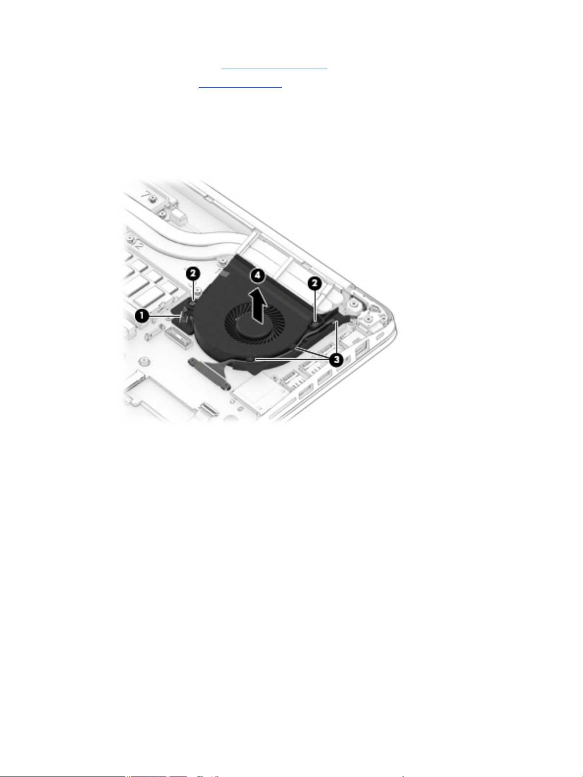
f. WWAN module (see WWAN module on page 42).
g. Speakers (see Speakers on page 49).
Remove the CPU (right) fan:
1. Release the fan connection (1) on the CPU (right) fan, and then loosen the two captive screws (2)
securing the CPU fan to the computer.
2. Release the display cable (3) and remove it from the guides around the fan, and then remove the fan (4)
from the computer.
Remove the GPU (left) fan:
1. Release the connector(1) on the GPU (left) fan, and then loosen the two captive screws (2) securing the
GPU fan to the computer.
Component replacement procedures 55
Page 68
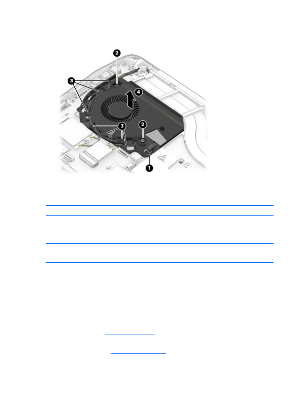
2. Release the WWAN cable and WLAN cable (3) from the routing around the fan, and then remove the fan
(4) from the computer.
Reverse this procedure to install the CPU (right) and GPU (left) fans.
Heat sink
Before removing the heat sink, follow these steps:
1. Turn o the computer. If you are unsure whether the computer is o or in Hibernation, turn the
2. Disconnect the power from the computer by unplugging the power cord from the computer.
3. Disconnect all external devices from the computer.
4. Remove the following components:
Description Spare part number
Heat sink for use only with models with NVIDIA N17EQ1 discrete graphics memory 922842-001
Heat sink for use only with models with NVIDIA N17PQ1 discrete graphics memory 922843-001
Heat sink for use only with models with NVIDIA N17PQ3 discrete graphics memory 922844-001
Heat sink for use only with models with AMD UMA graphics memory 922845-001
Heat sink for use only with models with UMA graphics memory 922846-001
computer on, and then shut it down through the operating system.
a. Service door (see Service door on page 30).
b. Battery (see Battery on page 31).
c. Base enclosure (see Base enclosure on page 33).
56 Chapter 6 Removal and replacement procedures for authorized service provider parts
Page 69
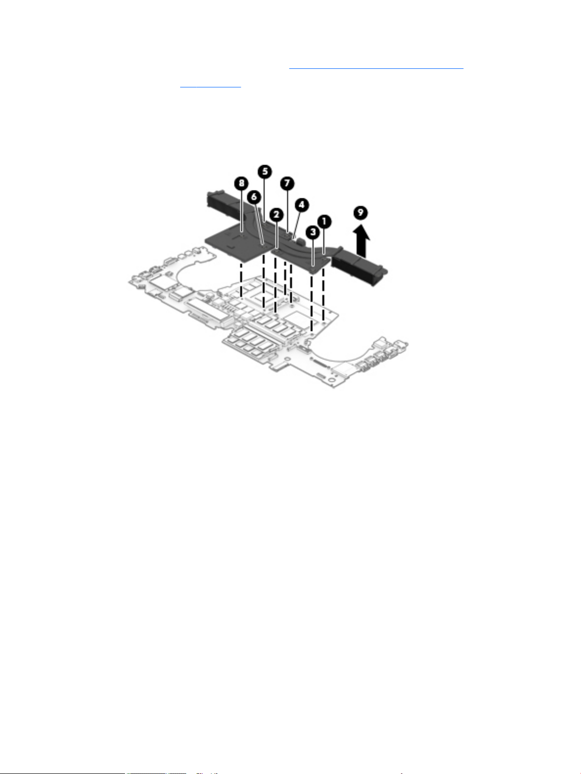
d. Hard drive(s) and internal frame (see Hard drive(s) and internal frame on page 33).
e. Fans (see Fan on page 54).
Remove the heat sink:
Heat sink for use with models with discrete graphics memory
1. Remove the screws in the order shown (1 – 8) and then remove the heat sink (9) from the system board.
Component replacement procedures 57
Page 70
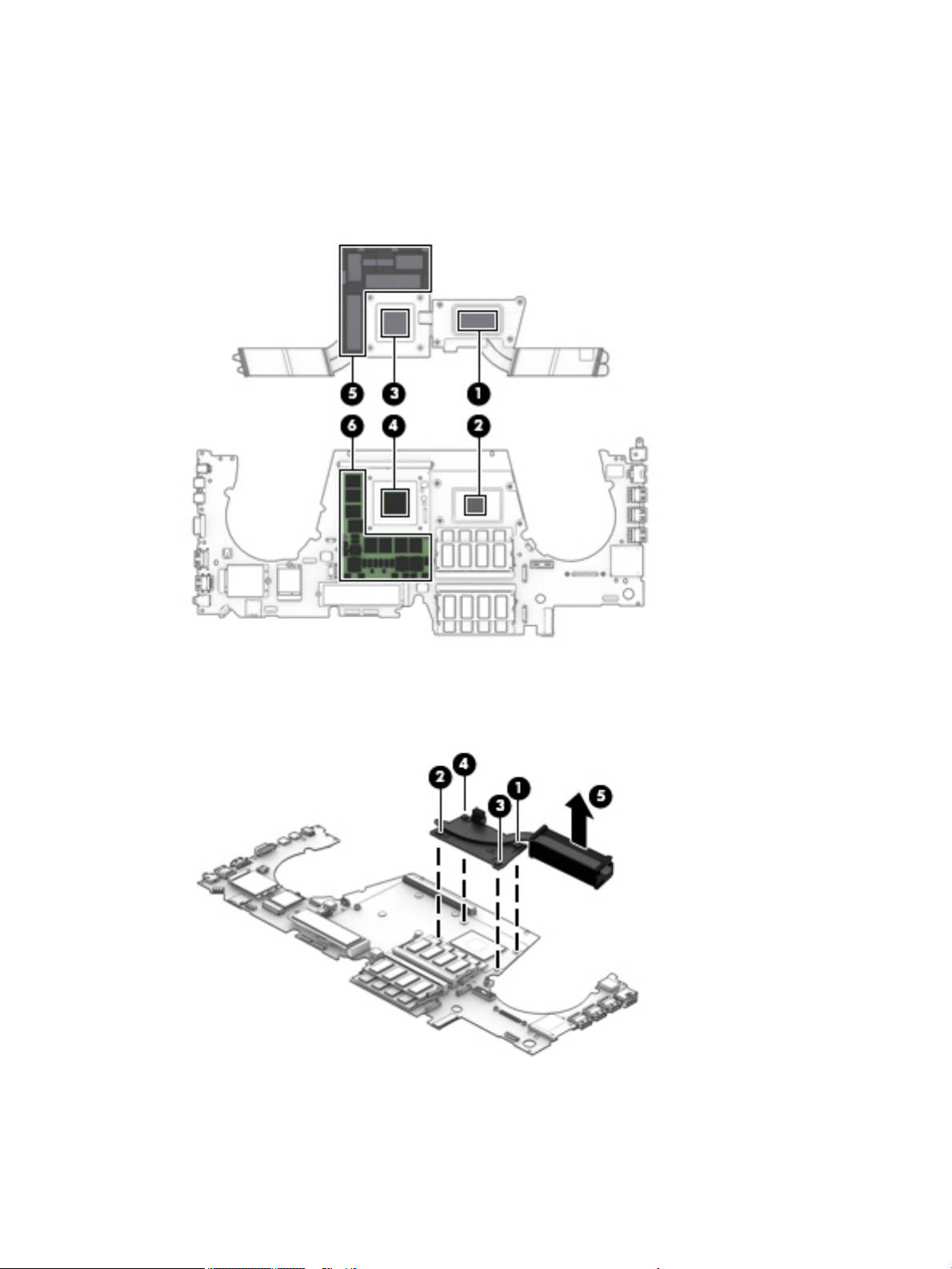
2. The following illustration shows the replacement thermal material locations. The thermal material must
be thoroughly cleaned from the surfaces of the heat sink and the system board components each time
the heat sink is removed. Replacement thermal material is included with the heat sink and system board
spare part kits.
Thermal paste is used on the system board components (2), (4), (6) and on the heat sink areas (1), (3),
(5) that service them.
Heat sink for use with models with UMA graphics memory
1. Loosen the screws in the numbered order shown (1, 2, 3, 4), and then remove the heat sink (5) from the
system board.
58 Chapter 6 Removal and replacement procedures for authorized service provider parts
Page 71
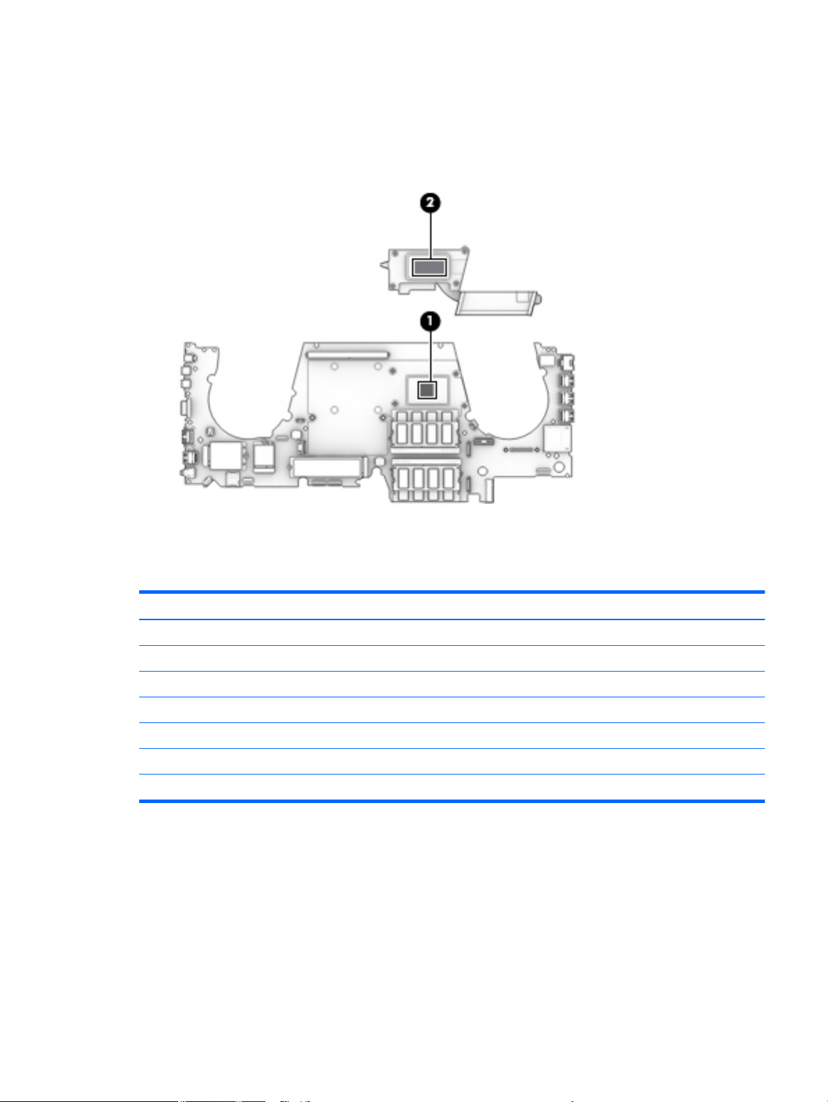
2. The following illustration shows the replacement thermal material locations. The thermal material must
be thoroughly cleaned from the surfaces of the heat sink and the system board components each time
the heat sink is removed. Replacement thermal material is included with the heat sink and system board
spare part kits.
Thermal paste is used on the system board component (1) and on the heat sink area (2) that services it.
Reverse this procedure to install the heat sink.
Discrete graphics board
Description Spare part number
NVIDIA Quadro M12000 with 4 GB graphics subsystem memory 917108-001
NVIDIA Quadro M2200 with 4 GB graphics subsystem memory 917109-001
NVIDIA Quadro M3000M: NVIDIA N16E-Q1 with 4 GB GDDR5 graphics subsystem memory 917109-001
NVIDIA Quadro P3000 with 6 GB graphics subsystem memory 917110-001
NVIDIA Quadro P4000 with 8 GB graphics subsystem memory 917111-001
NVIDIA Quadro P5000 with 16 GB graphics subsystem memory 917112-001
AMD Radion Pro WX 4170M with 4 GB GDDR5 graphics subsystem memory 917107-001
Before removing the discrete graphics board, follow these steps:
1. Turn o the computer. If you are unsure whether the computer is o or in Hibernation, turn the
computer on, and then shut it down through the operating system.
2. Disconnect the power from the computer by unplugging the power cord from the computer.
3. Disconnect all external devices from the computer.
4. Remove the following components: .
Component replacement procedures 59
Page 72
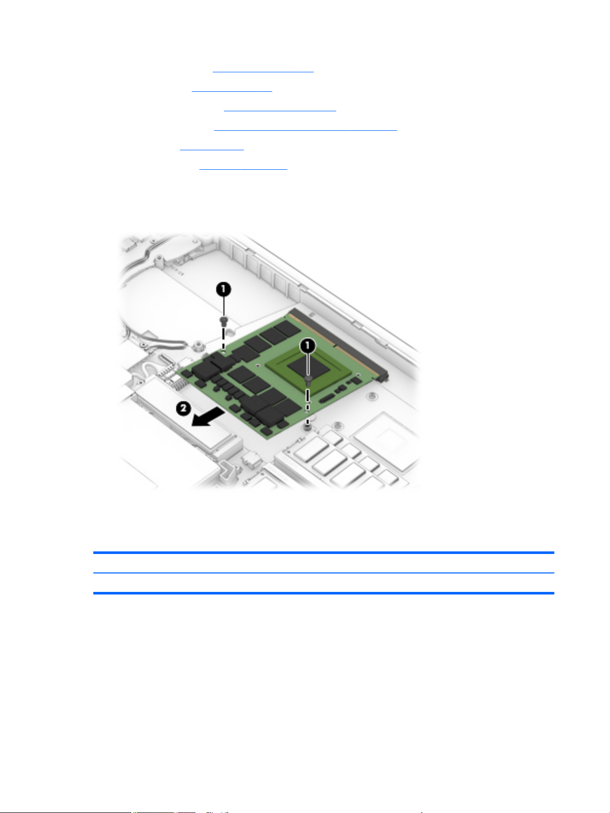
a. Service door (see Service door on page 30).
b. Battery (see Battery on page 31).
c. Base enclosure (see Base enclosure on page 33).
d. Hard drive(s) (see Hard drive(s) and internal frame on page 33).
e. Fans (see Fan on page 54).
f. Heat sink (see Heat sink on page 56).
Remove the discrete graphics board:
▲
Remove the two screws (1) securing the board to the system board, and then remove the discrete
graphics board (2).
Reverse this procedure to install the discrete graphics board.
Display LED board
Description Spare part number
Display LED board
Before removing the display LED board, follow these steps:
1. Turn o the computer. If you are unsure whether the computer is o or in Hibernation, turn the
computer on, and then shut it down through the operating system.
2. Disconnect the power from the computer by unplugging the power cord from the computer.
3. Disconnect all external devices from the computer.
4. Remove the following components:
60 Chapter 6 Removal and replacement procedures for authorized service provider parts
Page 73
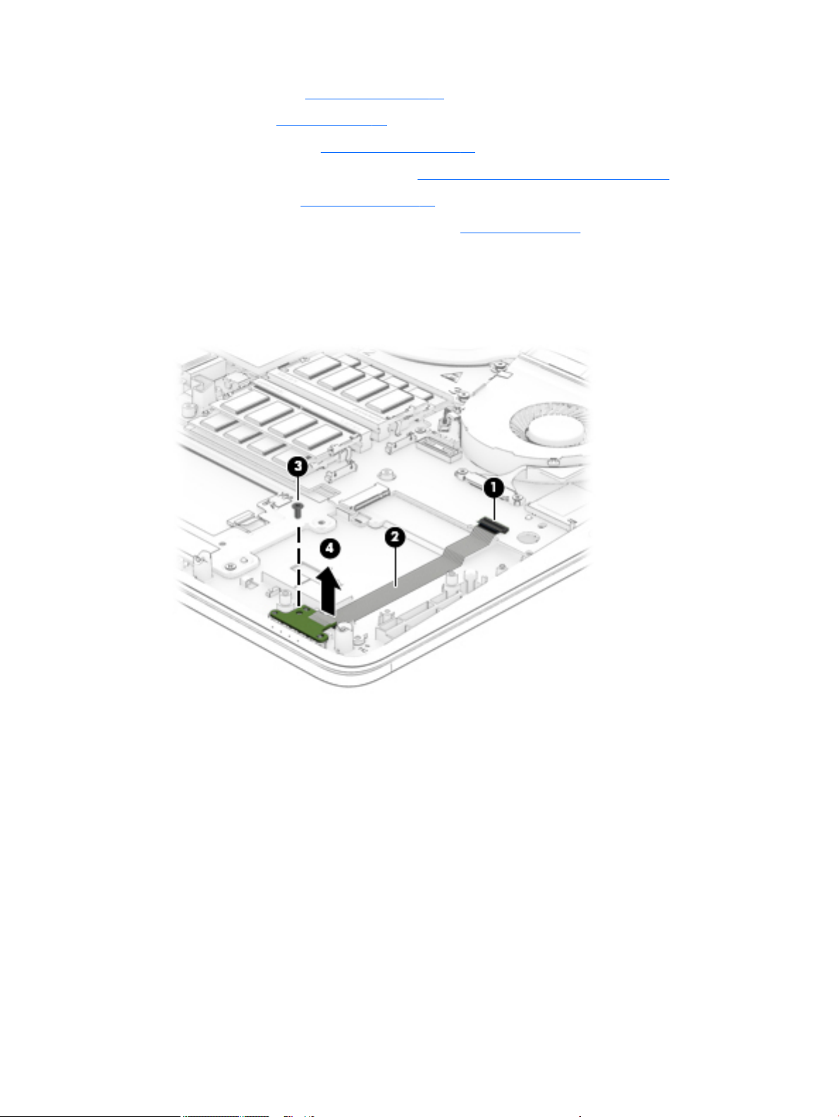
a. Service door (see Service door on page 30).
b. Battery (see Battery on page 31).
c. Base enclosure (see Base enclosure on page 33).
d. Hard drive(s) and internal frame (see Hard drive(s) and internal frame on page 33).
e. RTC battery (see RTC battery on page 48).
f. Right speaker and metal speaker frame (see Speakers on page 49).
Remove the display LED board:
1. Open the ZIF connector (1) on the system board to release the display LED board ribbon cable, and then
release the ribbon cable (2) from the adhesive securing it to the computer.
2. Remove the screw (3) securing the board to the computer, and then remove the display LED board (4).
Reverse this procedure to install the display LED board.
Component replacement procedures 61
Page 74

Keyboard
For use in country or region Spare part
number
Keyboard with backlight:
For use in Belgium 848311-A41 For use in Northwest Africa 848311-FP1
For use in Brazil 848311-201 For use in Norway 848311-091
For use in Bulgaria 848311-261 For use in Portugal 848311-131
For use in Canada 848311-DB1 For use in Romania 848311-271
For use in the Czech Republic and Slovakia 848311-FL1 For use in Russia 848311-251
For use in Denmark 848311-081 For use in Saudi Arabia 848311-171
For use in France 848311-051 For use in Slovenia 848311-BA1
For use in Germany 848311-041 For use in South Korea 848311-AD1
For use in Greece 848311-151 For use in Spain 848311-071
For use in Hungary 848311-211 For use in Sweden and Finland 848311-B71
For use in Iceland 848311-DD1 For use in Switzerland 848311-BG1
For use in India 848311-D61 For use in Taiwan 848311-AB1
For use internationally 848311-B31 For use in Thailand 848311-281
For use in Israel 848311-BB1 For use in Turkey 848311-141
For use in country or region
Spare part number
For use in Italy 848311-061 For use in the United Kingdom and
Singapore
For use in Japan 848311-291 For use in the United States 848311-001
For use in Latin America 848311-161
848311-031
Before removing the keyboard, follow these steps:
1. Turn o the computer. If you are unsure whether the computer is o or in Hibernation, turn the
computer on, and then shut it down through the operating system.
2. Disconnect the power from the computer by unplugging the power cord from the computer.
3. Disconnect all external devices from the computer.
4. Service door (see Service door on page 30).
a. Battery (see Battery on page 31).
b. Base enclosure (see Base enclosure on page 33).
c. Hard drive(s) and internal frame (see Hard drive(s) and internal frame on page 33).
Remove the keyboard:
1. Partially open the computer.
2. Rest and secure the computer on its left side and remove the two screws (1) securing the keyboard to
the computer.
62 Chapter 6 Removal and replacement procedures for authorized service provider parts
Page 75
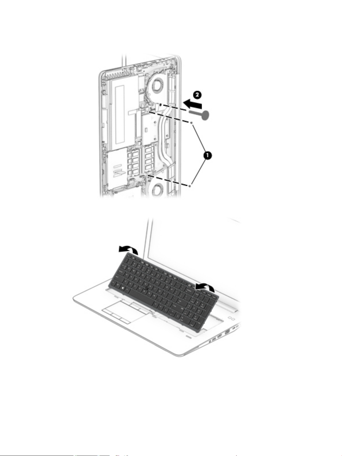
3. Insert a thin tool (2) into the keyboard release hole beside the second fan, and then press on the back of
the keyboard until the keyboard disengages from the computer.
4. Swing the keyboard up and forward until it rests upside down on the palm rest.
5. Open the ZIF connector (1) on the system board to release the keyboard ribbon cable.
6. Open the ZIF connector (2) on the system board to release the backlight cable.
7. Open the ZIF connector (3) on the system board to release the pointing stick cable.
Component replacement procedures 63
Page 76
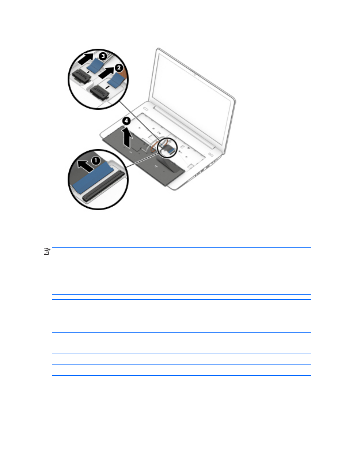
8. Remove the keyboard (4).
Reverse this procedure to install the keyboard.
System board
NOTE: The system board spare part kit includes battery connector bracket and replacement
thermal material.
All system boards use the following part numbers:
xxxxxx-001: Windows 7 or non-Windows operating systems
xxxxxx-601: Windows 10 operating system
Description Spare part number
Intel Core i5-7300HQ processor 921325-xxx
Intel Core i5-7440HQ processor 921326-xxx
Intel Core i7-7700HQ processor 921327-xxx
Intel Core i7-7820HQ processor 921328-xxx
E3-1535M processor 921329-xxx
E3-1505M processor 921330-xxx
Before removing the system board, follow these steps:
64 Chapter 6 Removal and replacement procedures for authorized service provider parts
Page 77

1. Turn o the computer. If you are unsure whether the computer is o or in Hibernation, turn the
computer on, and then shut it down through the operating system.
2. Disconnect the power from the computer by unplugging the power cord from the computer.
3. Disconnect all external devices from the computer.
4. Remove any SD card or SD blank from the computer.
5. Remove the following components:
a. Service door (see Service door on page 30).
b. Battery (see Battery on page 31).
c. Base enclosure (see Base enclosure on page 33).
d. Hard drive(s) and internal frame (see Hard drive(s) and internal frame on page 33).
e. WLAN module (see WLAN module on page 40).
f. WWAN module (see WWAN module on page 42).
g. Memory modules (see Memory module on page 44).
h. Solid-state drive(s) (see Solid-state drives (M.2) on page 38).
i. Fans (see Fan on page 54).
j. Heat sink (see Heat sink on page 56).
k. Discrete graphics board (see Discrete graphics board on page 59).
l. Keyboard (see Keyboard on page 62).
NOTE: When replacing the system board, be sure that the following components are removed from the
defective system board and installed on the replacement system board:
●
WLAN module (see WLAN module on page 40)
●
WWAN module (see WWAN module on page 42)
●
Memory module (see Memory module on page 44)
●
Heat sink (see Heat sink on page 56)
NOTE: You do not have to remove the heat sink to remove the system board.
Remove the system board:
1. Disconnect the following cables from the system board (note the routing location of the cables when
removing them):
(1) Speaker cable
(2) WWAN cable
(3) WLAN cable
(4) Fingerprint reader cable
(5) Smart Card reader cable
(6) Touchpad cable
(7) Display LED board cable
Component replacement procedures 65
Page 78
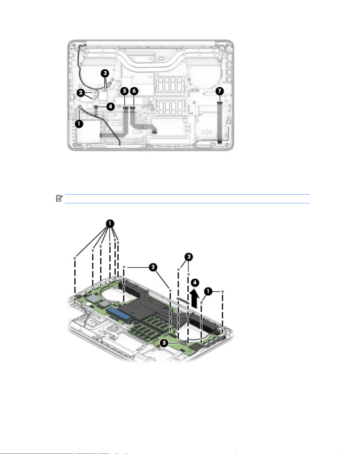
2. Remove the eight Phillips screws (1) securing the system board edges.
3. Remove the two Phillips screws (2) securing the system board.
4. Remove the two Phillips screws (3) securing the display cable bracket, and then remove the bracket (4).
NOTE: Use at tool under the connector to remove evenly. Do not pull on the cable to remove.
5. Release the connector (5) for the display cable.
66 Chapter 6 Removal and replacement procedures for authorized service provider parts
Page 79
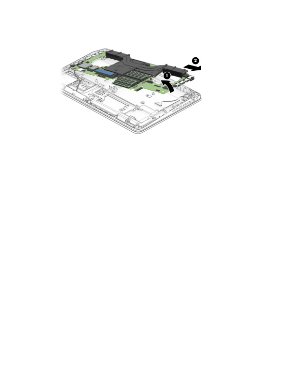
6. Lift the side of the system board (1) and slide system board (2) at angle away from the computer to
remove it.
Reverse this procedure to install the system board.
Component replacement procedures 67
Page 80

Display assembly
NOTE: The Dream Color display assembly is spared as a whole unit assembly only. The LED display assembly
is spared at the subcomponent level only. For more LED display assembly spare part information, see the
individual removal subsections.
Description Spare part number
17.3 FHD, UWVA AG with camera and touch screen 921322-001
17.3 in UHD, Dream Color 3 UWVA 921323-001
17.3 in UHD, Dream Color 3 UWVA f/camera 921324-001
Raw panel 17.3 FHDAGWLEDUWVA300eDP Flat AK 819347-002
Raw panel 17.3 HD+AGWLEDSVA 220eDP Flat AK 819348-002
Hinge 906120-001
LCD bezel with magnet 848368-001
Bezel with camera 850119-001
LCD cable 848379-001
Webcam, 1p DM U2 Mjpeg 720p CTS Vaughn 819336-006
Microphone board 854110-001
To remove the display assembly and access the LED display assembly subcomponents, follow these steps:
1. Turn o the computer. If you are unsure whether the computer is o or in Hibernation, turn the
computer on, and then shut it down through the operating system.
2. Disconnect the power from the computer by unplugging the power cord from the computer.
3. Disconnect all external devices from the computer.
4. Remove the following components:
a. Service door (see Service door on page 30).
b. Battery (see Battery on page 31).
Remove the display assembly:
1. Remove the six Phillips screws (1) that secure each hinge to the computer.
2. Open the computer as far as possible.
68 Chapter 6 Removal and replacement procedures for authorized service provider parts
Page 81
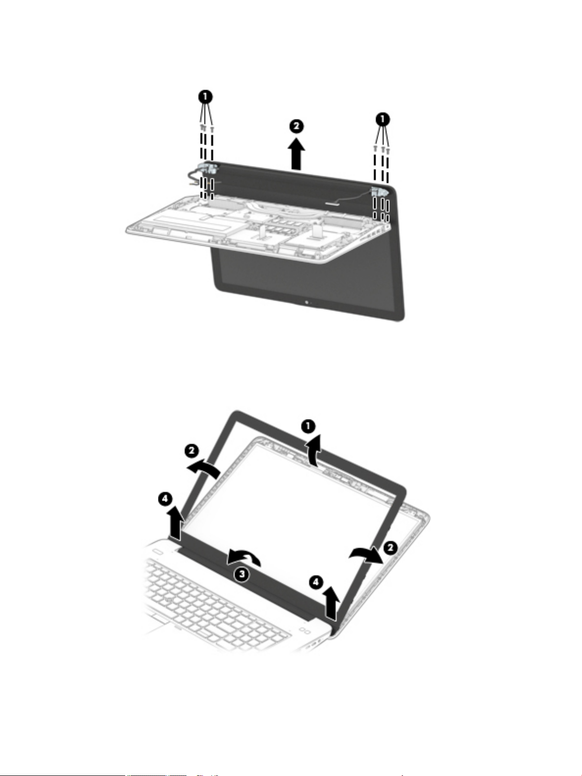
3. Separate the display from the computer (2).
4. If it is necessary to replace the display bezel or any of the LED display assembly subcomponents:
a. Use a plastic tool to disengage the bezel starting at the top (1), left and right sides (2), and bottom
(3).
b. Remove the display bezel (4).
5. If it is necessary to replace the display panel:
a. Remove the four Phillips screws (1) that secure the display panel to the display enclosure.
Component replacement procedures 69
Page 82
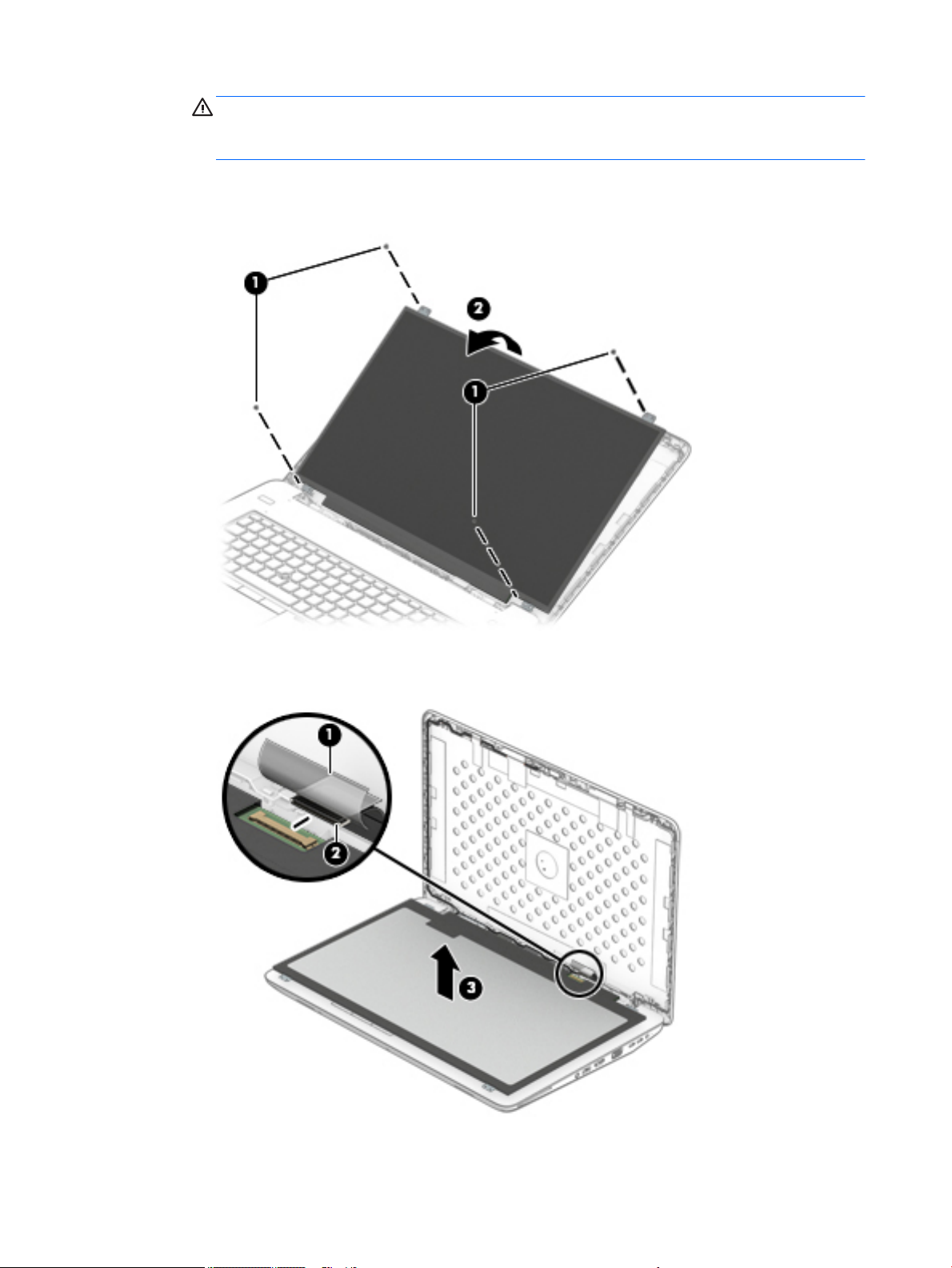
CAUTION: Before turning the display panel upside down, make sure the work surface is clear of
tools, screws, and any other foreign objects. Failure to follow this caution can result in damage to
the display panel.
b. Lift the top edge of the display panel (2) and swing it up and forward until it rests upside down in
front of the display enclosure.
c. Lift the tape (1), and then disconnect the display panel cable (2) from the display panel.
d. Remove the display panel display panel (3).
6. If it is necessary to replace the webcam module or microphone module:
70 Chapter 6 Removal and replacement procedures for authorized service provider parts
Page 83
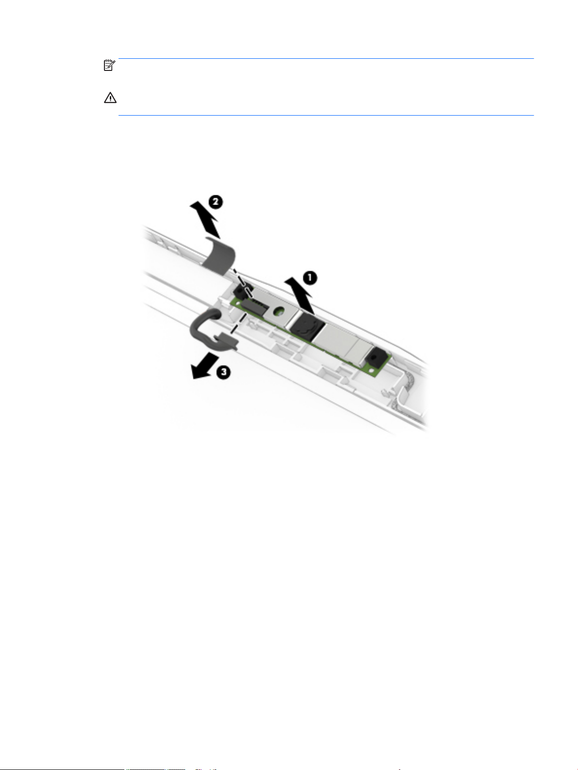
NOTE: The webcam module and microphone module are similar in appearance and installed in the
same location. The removal procedures are the same for both modules.
CAUTION: Handle the module with caution. This module has a thin prole and is susceptible to damage
when not handled carefully.
a. Detach the webcam or microphone module (1) from the display enclosure. (The module is attached
to the display enclosure with double-sided adhesive.)
b. Remove the tape (2) covering the cable.
c. Disconnect the module cable (3) from the module.
7. If it is necessary to replace the Dream Color calibration board:
a. Disconnect the calibration board cable (1) from the board.
Component replacement procedures 71
Page 84
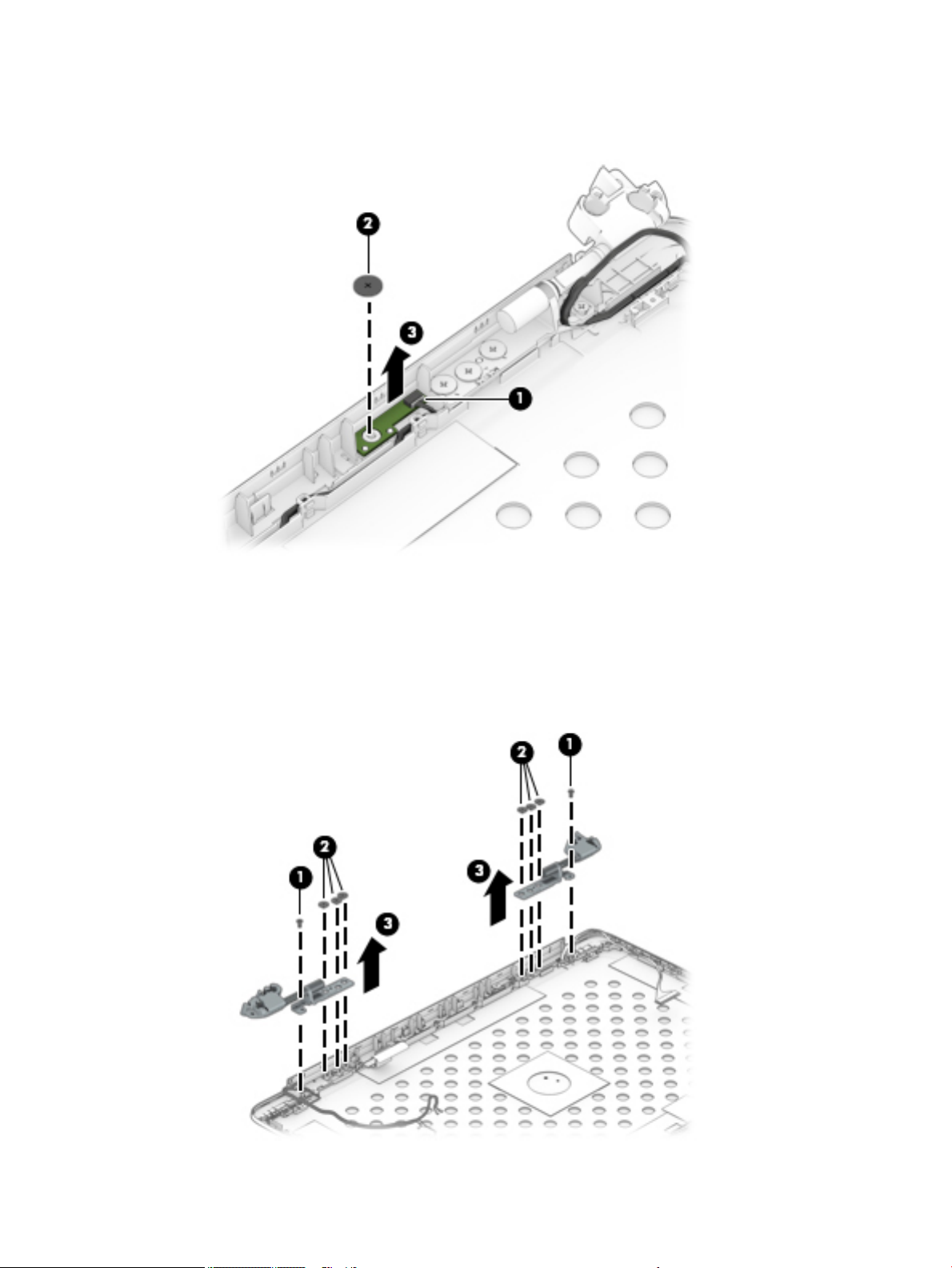
b. Remove the Phillips screw (2) securing the board, and then remove the board (3) from the display
enclosure.
8. If it is necessary to replace the display hinges:
a. Remove the two outer screws (1) and the six Phillips screws (2) that secure each display hinge to
the display enclosure.
b. Remove the display hinges (3).
The display hinges are available using the spare part number 848370-001 and include the left and
right hinges.
72 Chapter 6 Removal and replacement procedures for authorized service provider parts
Page 85
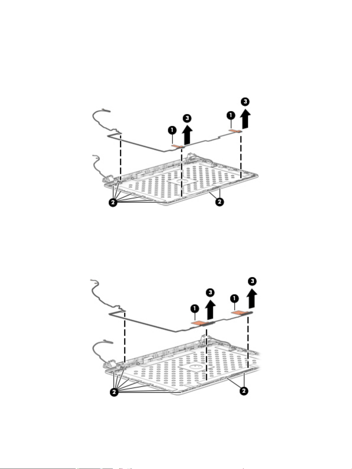
9. If it is necessary to replace the WLAN antennas:
a. Lift and remove the WLAN antennas (1) o the display enclosure.
b. Release the antenna cables (2) from the routing path of the display enclosure.
c. Remove the WLAN antennas (3) from the bottom of the display enclosure.
The antennas are available using spare part number 848346-001.
10. If it is necessary to replace the WWAN antennas:
a. Lift and remove the WWAN antennas (1) o the display enclosure.
b. Remove the antenna cables (2) from the routing path of the display enclosure.
c. Remove the WWAN antennas (3) from the bottom of the display enclosure.
The antennas are available using spare part number 848347-001.
11. If it is necessary to replace the display cable:
Component replacement procedures 73
Page 86
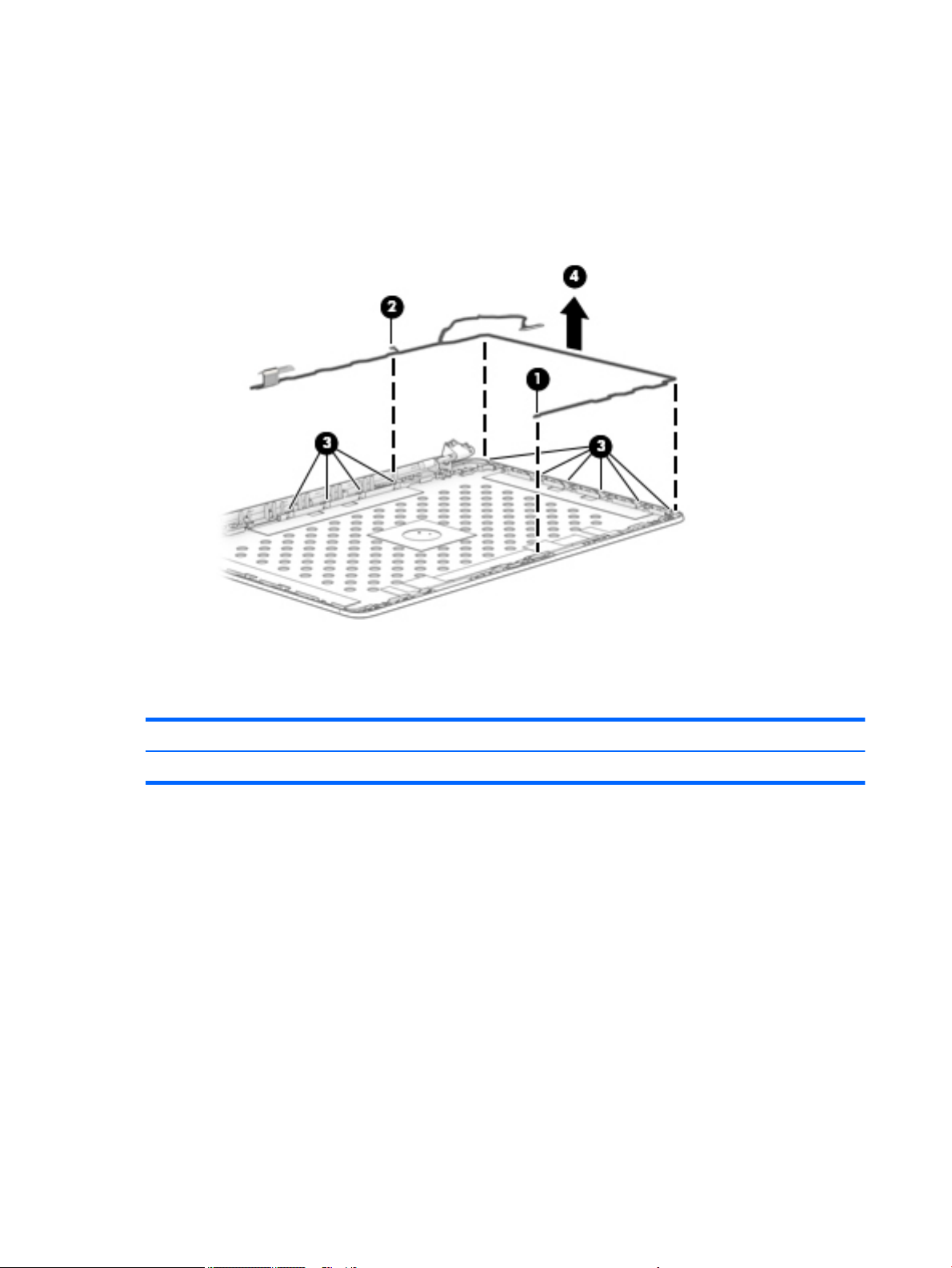
a. Disconnect the end of the display cable (1) from the connector securing it to the display enclosure.
b. Disconnect display cable (2) from the small connector securing it to the display enclosure.
c. Release the cable (3) from the routing path along the display enclosure.
d. Remove the cable (4).
The display cable is available using spare part number 848379-001.
Reverse this procedure to reassemble and install the display assembly.
Top cover
The top cover spare remains after removing all other spare parts.
Description Spare part number
Top cover 929011-001
74 Chapter 6 Removal and replacement procedures for authorized service provider parts
Page 87

7 Troubleshooting guide
This chapter is primarily focused on troubleshooting HP Mobile Workstations and HP Notebooks. The
information is provided so that you can solve problems yourself or at least narrow down what may be causing
the problem. Based on some of the most common symptoms, this chapter helps to identify logical steps and
available resources or tools for resolving an issue. HP recommends that you follow the instructions carefully,
observe safety precautions, and note any observations or results. Capturing this information may help
identify and resolve the problem faster.
WARNING! To reduce the risk of electric shock or damage to the equipment:
●
Do not disable the power cord grounding plug. The grounding plug is an important safety feature.
●
Plug the power cord into a grounded (earthed) outlet that is easily accessible at all times.
●
Disconnect power from the equipment by unplugging the power cord from the AC outlet.
●
Before disassembling notebooks, always disconnect power and remove the battery.
CAUTION: Static electricity can damage the electronic components of the computer. To prevent damage to
the computer, carefully observe the electrostatic discharge precautions.
●
Discharge static electricity by briey touching a grounded metal object before you begin.
●
Work on a static-free mat.
●
Wear a static strap to ensure that any accumulated electrostatic charge is discharged from your body to
the ground.
●
Create a common ground for the equipment you are working on by connecting the static-free mat, static
strap, and peripheral units to that piece of equipment.
●
Refer to the Electrostatic Discharge Section of the Maintenance & Service Guide for more information.
CAUTION: The computer includes customer self-repair parts and parts that should only be accessed by an
authorized service provider. See the chapter titled "Removal and replacement procedures for Customer SelfRepair parts," for details. Accessing parts described in the chapter titled "Removal and replacement
procedures for authorized service provider only parts" can damage the computer or void the computer
warranty.
75
Page 88

Resources
HP Resource Tool Description Link
HP Elite Support Provides live HP Premium support (available 24/7) to
Elite computers.
HP Support Center Provides important support, such as warranty,
support cases, drivers, Customer Advisories,
Customer and Security Bulletins, and Product Change
Notices.
HP Troubleshooting Support page Provides troubleshooting information for your
specic HP computer.
Troubleshooting Problems with
Docking Stations
HP Elite Dock with Thunderbolt 3
and HP ZBook Dock with
Thunderbolt 3
Subscribers Choice Allows you to sign up for HP product updates. http://www8.hp.com/us/en/subscribe/
HP Support Forums Provide discussions about HP products and issues. http://h30434.www3.hp.com/psg/
Service Access Workbench (SAW)
(Available for technicians and
Business Partners only)
Vendors’ web sites Provide additional information for associated
Provides troubleshooting information for HP docking
stations.
Provides troubleshooting information for your
specic docking station
Provides navigable content intended for use by
internal and outsourced call center sta and can be a
resource for support and product division
professionals.
components such as Intel (processor, WLAN),
Microsoft (Windows 7/8/10), AMD/NVidia (GPU), and
so on.
http://www8.hp.com/us/en/ads/eliteproducts/overview.html
http://h20565.www2.hp.com/portal/site/
hpsc
http://www8.hp.com/us/en/
troubleshooting.html
http://support.hp.com/us-en/document/
c03247469
http://h20565.www2.hp.com/hpsc/doc/
public/display?
sp4ts.oid=9822172&docLocale=en_US&d
ocId=emr_na-c05060909
http://sawpro.atlanta.hp.com/km/saw/
home.do
http://www.intel.com/
content/www/us/en/homepage.html
http://www.microsoft.com
http://www.amd.com
http://www.nvidia.com
General troubleshooting steps
A basic logic should be used when troubleshooting computer issues. This section will help you become
familiar with troubleshooting methodology and eciently resolve problems. Proceed through the steps in the
following table until the issue is resolved, and then move on to the next step that is relevant to the issue. For
example, if you resolve a memory issue using the HP PC Diagnostics (UEFI) tool in step 6, you can then move
on to step 10 to reseat the memory into its memory slot.
NOTE: General troubleshooting steps do not have to be followed in a specic order.
Table 7-1 Troubleshooting methodology and general troubleshooting steps
Identify issue Analyze issue Resolve issue Verify solution
1. Understand the issue
on page 77
2. Examine the environment
on page 79
3. Perform a visual inspection
of hardware on page 80
76 Chapter 7 Troubleshooting guide
5. Remove or uninstall recently
added hardware, software
on page 80
6. HP Hardware Diagnostics and
Tools on page 81
8. Hard reset on page 90
9. Soft reset (Default Settings)
on page 91
10. Reseat cables and connections
on page 91
Verify solution
on page 94
Page 89

Table 7-1 Troubleshooting methodology and general troubleshooting steps
Identify issue Analyze issue Resolve issue Verify solution
4. Update BIOS and drivers
on page 80
Identify the issue
1. Understand the issue
It is important to understand the issue that occurred, including related symptoms. It helps to understand the
basic computer boot-up sequence as well as the failure itself. The boot-up sequence and associated failures
are described below.
Boot up sequence
The computer performs several steps after you press the power button or restart the computer.
It is important to understand where in the boot-up sequence the symptoms occur. The following table lists
the phases of the boot-up sequence and explains the symptoms that may occur in each phase. For example, a
blue screen error (BSOD) often occurs during the performance phase.
Table
7-2 Boot-up sequence
7. Status lights, blinking light
codes, troubleshooting lights,
and POST error messages
on page 85
11. Test with minimum conguration
on page 92
12. Test with veried working
conguration (hardware and/or operating
system) on page 93
13. Replace the system board on page 93
Item Description
Power-on After power button is pressed, the computer boots after all internal power rails (i.e., 5V, 3.3V) are stable.
POST (UEFI/BIOS) Power-On Self-Test (POST) veries that hardware components (processor, hard drive, memory, etc.) are
Performance
(operating system)
Failure classication
Failure classication is a breakdown of dierent types of failures and symptoms that could occur during the
boot-up sequence. Table 3 and table 4 represent the failure classication for common notebook failures.
Conrm that power lights are on fan is spinning.
Next step: If the computer experiences a power-on issue, see “Verify Power Good (Troubleshooting) lights” in
No Power on page 96.
Common issues: all lights are o; troubleshooting lights are on; does not boot; video is absent.
functional. When POST is complete, the HP logo displays briey and then disappears.
If there are errors, the computer may exhibit blinking lights and POST error messages
Common issues: lights blink, error message appears, hangs.
System boots to operating system, and Windows logo screen appears..
Common issues: hangs (lock up/freezes), blue screen, video distorted, driver conict, slow performance,
display issue (dead pixel), I/O issue (no speaker sound), wireless/audio unavailable, noise.
See Analyze the issue on page 80 table below for detailed troubleshooting information).
Table 3 categorizes failures by the boot-up sequence.
General troubleshooting steps 77
Page 90

1. Power-on: Common issues are No Power, Recycle/Reboot, etc.
2. POST: Common issues are No Boot (have power), Light Flash or Diagnostics Error.
3. Performance: Common issues are Intermittent Loss of Power, Blue Screen, Hang, etc. In many cases,
issues may be identied and associated with a particular hardware (i.e., display, storage).
Table 4 categorizes failures by hardware.
4. Display
5. I/O devices (Input/Output)
6. Storage
7. Mechanical
A single symptom can be listed under dierent groups. For example, No Video can belong to (1) Power-on or
(4) Display; but Flickering when powered should be listed in (4) Display. Or, in another example, a blue screen
can be caused by a driver conict in Performance (4), but it can also be caused by a defective hard drive under
(6) Storage. Therefore, failures that share similar symptoms are noted..
If possible, make a record of the failure symptom, the phase of the boot-up sequence where the failure
occurs, and the most likely location in the failure tree (Table 7-3 Failure classication by boot-up sequence
on page 78 and Table 7-4 Failure classication by hardware devices and mechanical on page 79). This will
help isolate the issue and indicate the next steps. For example, when the computer is running the operating
system, it may experience an issue with (4) Display, (5) I/O devices (keyboard, wireless, and so on), (6)
Storage, or (7) Mechanical components (stuck buttons, thermal shutdown, and so on).
NOTE: “Uncategorized” is used if an issue found is not listed. For example, Bluetooth is oered on certain
hardware congurations; therefore, a Bluetooth issue can be classied under “I/O Device” if needed.
Failure classication by boot-up sequence
Table
7-3 Failure classication by boot-up sequence
1. Power-on 2. POST 3. Performance
1. No Power on page 96
2. Intermittent power-on, shutdown,
reboot on page 98
3. AC adapter issue on page 100
4. Battery not recognized, not charging
on page 100
5. Battery discharges too fast
on page 102
6. Burnt smell on page 103
a,b,c
similar symptoms
a
1. No video (with power)
on page 103
2. Blinking lights on page 104
3. Diagnostics error messages
on page 105
4. BIOS password on page 106
1.
Intermittent shutdown on page 107
2.
Blue screen (BSOD) error on page 134
3. Freeze at Windows Logo (hang/lockup)
on page 110
4. Electromagnetic Interference (EMI)
on page 111
5. No wake up on page 112
6. Unresponsive on page 113
7.
Slow performance on page 113
8. HP Smart Adapter warning message
on page 114
9. Incorrect time and date on page 114
a
c
b
78 Chapter 7 Troubleshooting guide
Page 91

Failure classication by hardware devices and mechanical
Table 7-4 Failure classication by hardware devices and mechanical
4. Display 5. I/O devices 6. Storage 7. Mechanical
1. Display anomalies
on page 115
2. Dead pixel on page 117
3. No video (internal)
on page 117
4. No video (external)
on page 118
5. DisplayPort/VGA
on page 118
6. HDMI on page 118
7. No or bad external video
via docking on page 119
8. Incorrect or missing color/
distorted image
on page 119
9. Touch screen
on page 120
b,c,d
similar symptoms
d
d
1. Keyboard on page 121
2. Keyboard point stick
on page 122
3. Keyboard backlight
on page 122
4. TouchPad on page 123
5. Network Connectivity
Ethernet (RJ-45 jack)
on page 123
6. Network connectivity
wireless (WLAN)
on page 124
7. WWAN on page 125
8. USB on page 126
9. Smart card reader
on page 127
10. Speaker, headphone audio issues on page 128
11. Thunderbolt (TB)
on page 129
12. Thunderbolt 3 dock
on page 130
1. Hard drive/solid-state
drive not recognized
on page 133
2. No boot to operating
system (no read/write
error) on page 133
3. Read-write error
on page 134
4. Slow performance
on page 113
5. Blue screen (BSOD) error
on page 134
6. Noisy hard drive
on page 135
c
b
1. Fan error message - 90B
on page 136
2. Noise (sound)
on page 137
3. Fan runs constantly
on page 138
4. HP Thermal Monitor
on page 84
5. Stuck power button
on page 140
2. Examine the environment
It is important to examine the computer’s environment. If you can quickly identify the cause of the issue,
fewer resolution steps may be needed. Perform the following environment inspections:
●
Check all cables and connections to be sure that there are no loose connections.
●
Conrm that power sources are good, such as wall power type/adapter (110V/220V ac), power strip. Test
with a veried working AC outlet.
●
Check for compatibility issues between the computer and third-party devices, peripherals, noncertied
devices, incompatible hardware (i.e., Mac OS device). Incompatibility can result in blue screen errors,
improper operation, and so on.
●
Isolate the computer from sources of electromagnetic interference (EMI), such as cell phones, 2-way
radios, oor mats, fans (and other electronic motors). EMI may contribute to a display freeze issue or
lock-up.
General troubleshooting steps 79
Page 92

3. Perform a visual inspection of hardware
It is important to do a visual inspection of the hardware itself. Perform physical inspection of the computer:
●
Look for abnormalities such as a cracked display, dented battery, broken latches for battery bay,
keyboard key caps popped out, dust over connectors, liquid spill over keyboard, etc.
●
Look for signs of drop, movement, or vibration that may cause internal and external loose connections.
4. Update BIOS and drivers
IMPORTANT: Whenever possible, update to the latest BIOS, rmware, and drivers before troubleshooting.
Note that some customer company policies prohibit updates. Check your company policy before taking action.
The updates may include xes for your computer issues, and they may also enhance system performance. HP
continually improves the update process to make it easier. The BIOS update can be done locally through a
manual process, through an automatic installation, or through a remote installation on multiple units.
Manually updating BIOS and drivers
●
See the Computer Setup chapters to manually update BIOS and drivers.
●
Refer to specic BIOS update installation instructions that accompany the download.
Remotely deploying BIOS and drivers
Instead of manually searching for and downloading each SoftPaq, users and IT personnel can use two tools to
identify and download all appropriate SoftPaqs for the selected HP models.
●
HP SoftPaq Download Manager (SDM) is a software tool designed to streamline the download,
extraction, and installation process of SoftPaqs, including BIOS and drivers.
●
HP System Software Manager (SSM) is a software tool designed to simplify the deployment of SoftPaqs
to HP computers.
Analyze the issue
5. Remove or uninstall recently added hardware, software
HP has designed this computer and validated it using a full-range hardware and software qualication matrix.
If an issue appears to have started recently, it may be related to the recent addition of hardware or software.
A good method to determine the root cause is to remove recently added components or uninstall applications
one at a time and restart the computer when necessary.
IMPORTANT: After you have completed the process of uninstalling hardware or software and are ready to
reinstall, when installing a new device be sure that it is seated properly and all cables are correctly connected.
After installing the device, restart the computer and make sure the new device is powered on. In addition, if
the new device is a root cause of a problem, it could cause a conict in drivers or incompatibility issues with
other programs installed. For any new hardware you have added, be sure to install the latest drivers available
from the device vendor website.
80 Chapter 7 Troubleshooting guide
Page 93

6. HP Hardware Diagnostics and Tools
HP oers dierent diagnostics and tools to diagnose hardware failure. This section describes how to use
some of these tools. Make sure to check for the latest versions before use.
HP PC Hardware Diagnostics (UEFI)
HP PC Hardware Diagnostics is a Unied Extensible Firmware Interface (UEFI) that allows you to run diagnostic
tests to determine whether the computer hardware is functioning properly. The HP PC Hardware Diagnostics
(UEFI) tool is built within BIOS (basic memory and hard drive diagnostics only), or within new hard drives
themselves. These drives contain more advanced versions of the diagnostic tool than the BIOS-based version.
In addition, for HP authorized service partners and IT professionals who need to support a mixed environment
of older and newer HP/Compaq PCs, the HP PC Diagnostics 3-in-1 USB Key at http://www8.hp.com/us/en/
campaigns/hpsupportassistant/pc-diags.html?jumpid=va_r602_us/en/any/pps/pl_ot_ob_ds_pd/
HP_PC_Hardware_Diagnostics_cc/dt is a diagnostic tool that supports a wide range of HP Desktop and
Notebook computers.
The tool runs outside the operating system so that it can isolate hardware failures from issues that are
caused by the operating system or other software components. In reality, many problems can be determined
using this tool if the issue is a defective part or a loose connection (i.e., reseating keyboard cable after the
tool reports a keyboard error).
The tool has three major functions:
●
System Tests - Check the computer’s hardware to assure everything is functioning properly. If your
system won’t boot into Windows, try the Quick System Test. For more comprehensive testing, use the
Extensive System Test option. If the System Test did not detect a hardware problem, continue with the
Component Tests.
●
Component Tests – Focus on selected hardware components in your computer.
●
Firmware Management – Update your computer’s BIOS to the latest version (available separately) or roll
back to a previous version.
To start HP PC Hardware Diagnostics (UEFI):
1. Turn on or restart the computer, quickly press the esc button on the computer, and then press F2. The
BIOS searches three places for the diagnostic tools, in the following order:
a. Connected USB drive
b. Hard drive
c. BIOS
General troubleshooting steps 81
Page 94
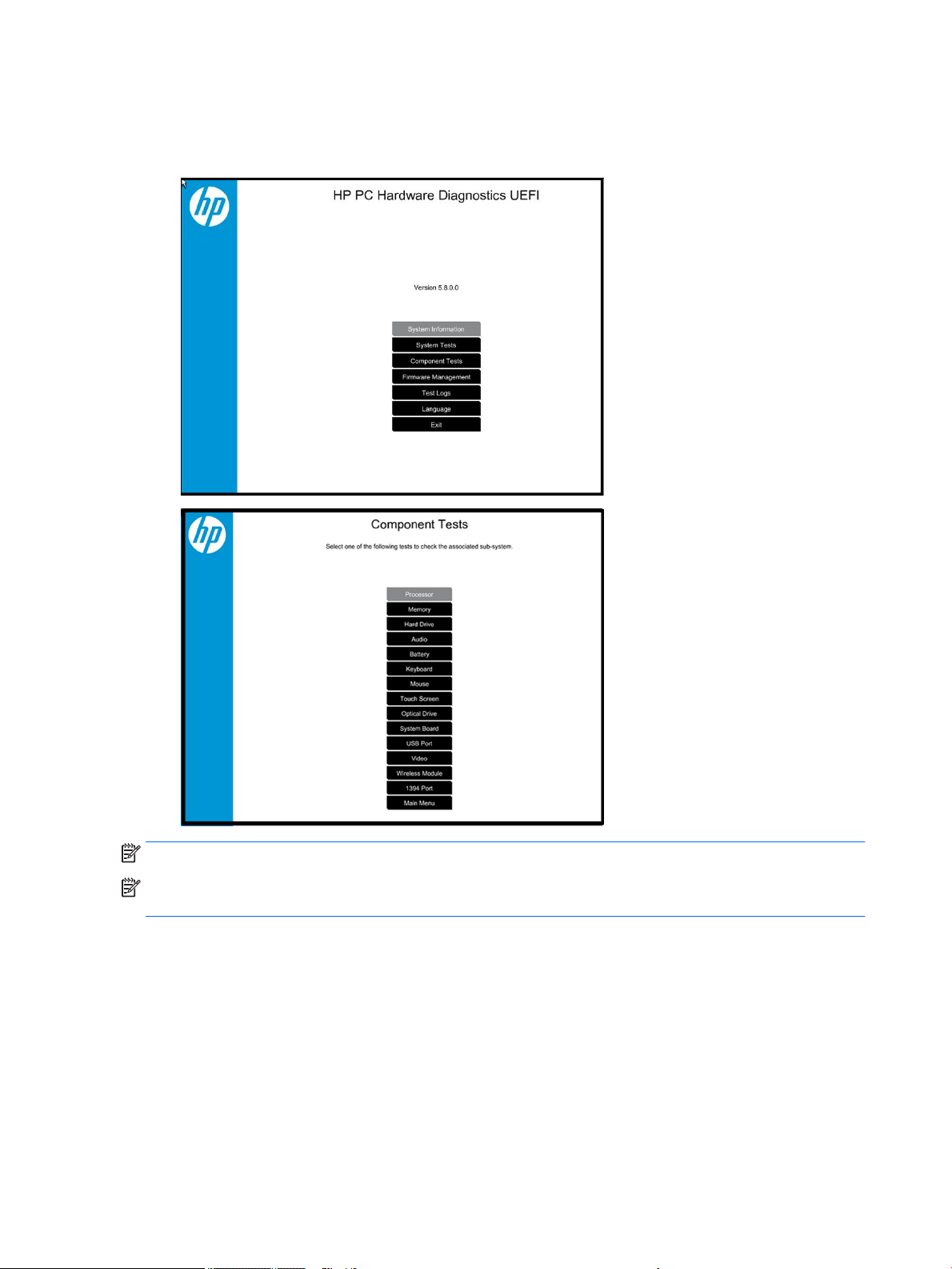
2. When the diagnostic tool opens, use the keyboard arrow keys to select the type of diagnostic test you
want to run, and then follow the on-screen instructions.
Screen shot appearance may vary.
NOTE: Users should utilize this tool, especially when the computer cannot boot to Windows.
NOTE: If a component fails a test, write down the information so it is available when contacting support.
The information is also available in Test Logs on the Main Menu.
For more information, see the chapter titled “Using HP PC Hardware Diagnostics (UEFI).”
82 Chapter 7 Troubleshooting guide
Page 95
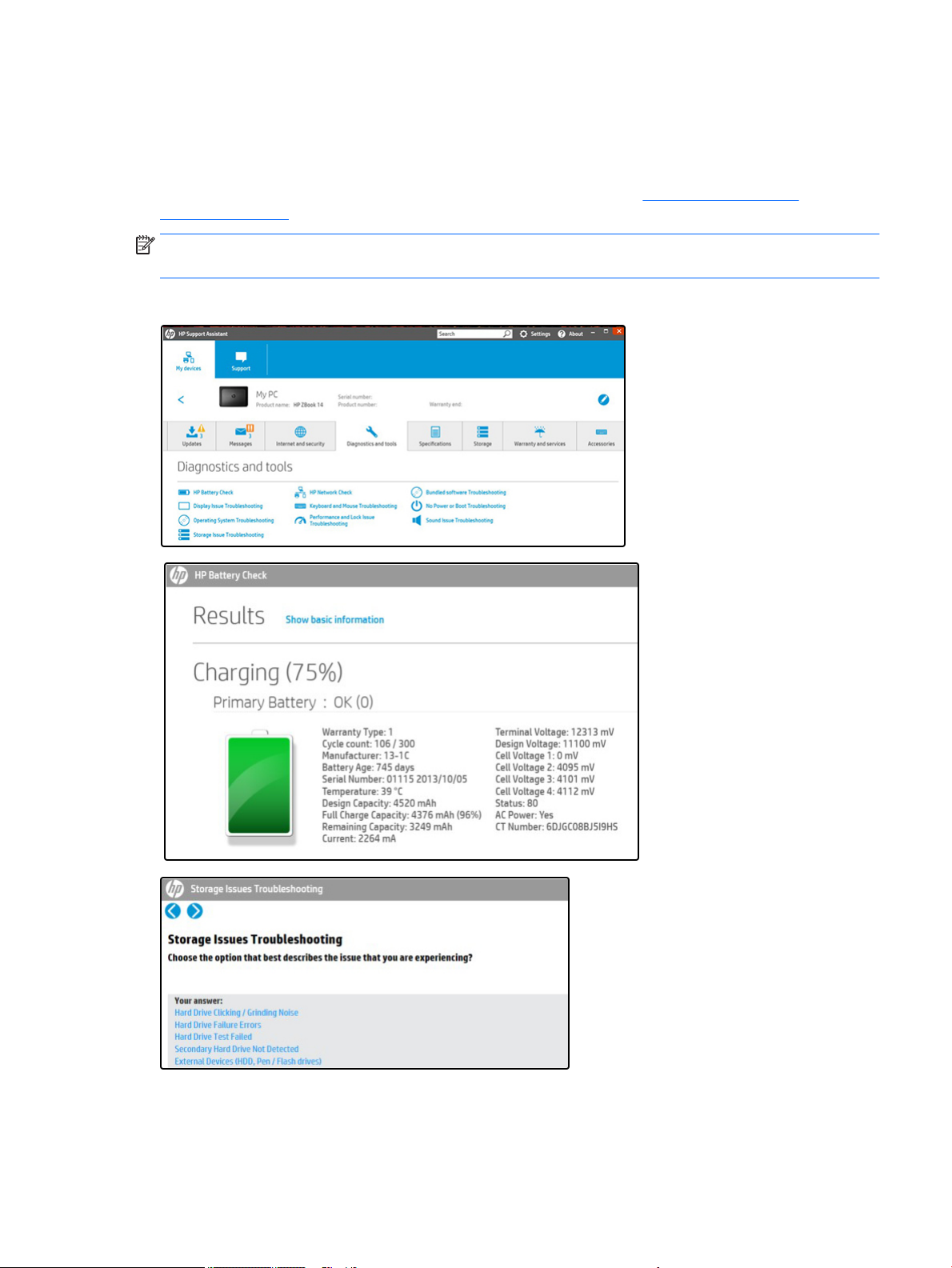
HP Support Assistant (HPSA)
HP Support Assistant (HPSA) helps you maintain peak performance and resolve problems through automatic
updates, built-in diagnostics, and a variety of assistance options. HPSA is preinstalled on every new HP PC
with Windows 7, Windows 8, or Windows 10. HP is continually improving this tool. Please verify the latest
version is installed to receive the most benet. For more information, see http://www.hp.com/go/
hpsupportassistant.
NOTE: HPSA can be used only if the computer boots into Windows. If the computer does not boot into
Windows, use HP PC Hardware Diagnostics (UEFI) instead.
HPSA also integrates diagnostics and tools that help resolve issues. See example screen shots as follows.
General troubleshooting steps 83
Page 96

HP BIOS Conguration Utility (BCU)
HP BCU is a free utility that captures the BIOS settings and their values. This tool provides a text le of the
computer’s BIOS conguration. This can help identify any settings that may be contributing to an issue.
In some cases, it may help to compare this BIOS text le to the default settings of the computer.
For more information, see the HP BIOS Conguration Utility (BCU) User guide at http://ftp.hp.com/pub/caps-
softpaq/cmit/whitepapers/BIOS_Conguration_Utility_User_Guide.pdf.
NOTE: HP recommends that you reset BIOS before trying BCU. Resetting the BIOS is always available and
relatively quick to try, whereas BCU takes extra time and eort.
HP Image Diagnostic Tool
Available to HP Authorized Support Partners (ASPs) and users from the HP public ftp site at
ftp://ftp.hp.com/pub/idr/ImageDiags/, this tool collects information about the current state of the computer,
including product serial number, platform and BIOS information, and information about user-installed
software and hardware components. HP encourages you to review the report before sending it to support.
The report may assist you with diagnostics and solutions to problems you encounter.
HP Thermal Monitor
NOTE: Available only to authorized service providers/technicians.
Available only for HP internal use, HP Thermal Monitor can be used to stress the processor and GPU and
monitor the temperature values of various components in the system. The components that are currently
monitored include the processor, GPU, ACPI thermal zones, hard drive, and battery. The tool reads the
temperatures of the components, logs the data, and helps to determine whether the computer would
overheat in the event of thermal shutdown, fan spinning loud, etc.
Non HP diagnostics tools
Windows-to-Go USB
Windows-To-Go USB is a Microsoft-based tool for Enterprise editions of Windows that can help in
troubleshooting. You can nd a process online about how to create a live Windows USB drive. For more
information, see https://technet.microsoft.com/en-us/library/hh831833.aspx.
Intel Processor Diagnostic Tool
Determine what processor is in your computer and verify the processor operating frequency. The tool also
tests specic processor features and performs a stress test on the processor. For more information, see
http://www.intel.com/support/processors/sb/CS-031726.htm?iid=subhdr+tools_procdiagtool.
84 Chapter 7 Troubleshooting guide
Page 97

7. Status lights, blinking light codes, troubleshooting lights, and POST error messages
Carefully observe any behavior the computer may be exhibiting: status lights, blinking lights, and POST error
messages during boot. It is important to understand what these indicators mean.
Status lights
See the chapter titled “External Component Identication” for light locations. The following table describes
basic lights on the computer.
Component Description
Power button When the computer is o, press the button to turn on the computer.
When the computer is on, press the button briey to initiate Sleep (Windows) or Suspend
(Linux).
When the computer is in the Sleep state, press the button briey to exit Sleep (Windows) or
Suspend (Linux).
When the computer is in Hibernation, press the button briey to exit Hibernation.
CAUTION: Pressing and holding down the power button results in the loss of unsaved
information.
If the computer has stopped responding and operating system shutdown procedures are
ineective, press and hold the power button.
Front power light On: The computer is on.
Blinking: The computer is in the Sleep state.
O: The computer is o.
Battery light White: The computer is connected to external power and the battery is charged from 90 to
99 percent.
Amber: The computer is connected to external power and the battery is charged from 0 to 90
percent.
Blinking amber: A battery that is the only available power source has reached a low battery
level. When the battery reaches a critical battery level, the battery light begins blinking
rapidly. By default, the critical battery level is dened in Power Options as 5%.
O: The battery is fully charged.
Front hard drive light Blinking white: The hard drive is being accessed.
Amber: HP 3D DriveGuard has temporarily parked the hard drive.
Rear AC adapter light White: The computer is connected to external power.
O: The computer is not connected to external power.
General troubleshooting steps 85
Page 98
Interpreting system validation diagnostic front panel LEDs and audible codes
During the system validation phase that occurs at system startup, the BIOS validates the functionality of the
following subsystems and conditions:
●
AC adapter
●
System board power
●
Processor failure
●
BIOS corruption
●
Memory failure
●
Graphics failure
●
System board failure
●
BIOS authentication failure
If an error is detected, specic patterns of long and short blinks, accompanied by long and short beeps (where
applicable) are used to identify the error. These patterns will make up a two part code:
●
Major – the category of the error
●
Minor – the specic error within the category
NOTE: Single beep/blink codes are not used.
Number of long beeps/blinks Error category
1 Not used
2 BIOS
3 Hardware
4 Thermal
5 System board
Patterns of blink/beep codes are determined by using the following parameters:
●
1 second pause occurs after the last major blink.
●
2 second pause occurs after the last minor blink.
●
Beep error code sequences occur for the rst 5 iterations of the pattern and then stop.
●
Blink error code sequences continue until the computer is unplugged or the power button is pressed.
NOTE: Not all diagnostic lights and audible codes are available on all models.
The red LED blinks to represent the major error category (long blinks). The white LED blinks to represent the
minor error category (short blinks). For example, ‘2.3’ indicates 2 long red blinks and 3 short white blinks to
communicate the processor is not detected. CAP/NUM Blink = 2 indicates CAP/NUM will blink 2 cycles, each
cycle has one 2.3 sequence.
86 Chapter 7 Troubleshooting guide
Page 99

Component
tested
Major/
minor
code Error condition
Caps
Lock/Num
Lock LED Action
BIOS 2.2 The main area (DXE) of BIOS has
become corrupted and there is no
recovery binary image available
2.3 The embedded controller policy
requires the user to enter a key
sequence (SureStart 2.0)
2.4 The embedded controller is
recovering the boot block or DXE.
Hardware 3.2 The embedded controller has timed
out waiting for BIOS to return from
memory initialization
3.3 The embedded controller has timed
out waiting for BIOS to return from
graphics initialization
3.4 The system board displays a power
failure (crowbar)
System board 5.2 The embedded controller cannot nd
valid rmware
CAP/NUM Blink
= 2
CAP/NUM Blink
= 8
Battery LED
White and
Amber
blinking
CAP/NUM Blink
= 3
CAP/NUM Blink
= 4
CAP/NUM Blink
= 5
CAP/NUM Blink
= 7 (2 BB
failure)
Battery LED
Blinking = 1 Hz
(3 B failure)
Contact service for system board replacement.
Perform SureStart manual recovery if boot
block: Up Arrow + Down Arrow + ESC.
Wait for DXE recovery to complete.
Reseat the memory modules. If the issue
persists, try replacing the memory modules.
Possible RAM or system board failure.
If the system has an MXM module, try a
dierent MXM module. Otherwise, the board
most likely needs to be replaced.
Check power cable connections, or verify that
any external power adapter has sucient
capacity for system.
Contact service for system board replacement.
5.3 The embedded controller has timed
POST error messages
The Power-On Self-Test (POST) is a series of diagnostic tests that runs automatically when the computer is
powered on. If the POST encounters a problem, visual error messages are displayed before the operating
system starts. POST checks the following items to ensure that the computer system is functioning properly:
●
Memory
●
Processors
●
BIOS
●
Mass storage devices
●
Fans
The following table describes key Post Error messages. For more detailed information, see POST Error
Messages and User Actions on page 144.
out waiting for the BIOS
CAP/NUM Blink
= 1
Contact service for system board replacement.
General troubleshooting steps 87
Page 100

Table 7-5 System diagnostics failure codes and user actions
Error
Test description Failure description
code Suggested user actions
Wireless Module not
supported
Front Audio Not
Connected
Startup Test Hard Disk 1 SMART 301 Attempt to reseat the hard drive and repeat the test. The hard
Boot Device Manager Boot device not found 3F0 Reset BIOS. Then reseat the hard drive and repeat the test.
BIOS Recovery BIOS Recovery Occurred 500 This message indicates that BIOS recovery was completed
BIOS Application BIOS Application Error 501 The BIOS installation may have become corrupted. Download the
The system has detected a
wireless module installed
in the system that is not
supported and has been
disabled.
WLAN Module ID (702)
WWAN Module ID (703)
Bluetooth Module ID (704)
GPS Module ID (705)
Front audio cable has been
detached or unseated from
the system motherboard.
70x Remove non-supported component.
100 Reseat the front audio cable on the system board.
drive may have failed.
successfully. No further action is required.
latest version of the BIOS and install it.
If reinstalling the BIOS fails, contact support for further
assistance.
CMOS Recovery CMOS Recovery Occurred 502 This message indicates that CMOS recovery was completed
successfully. No further action is required.
Battery Check Primary Battery Replace 601 This message indicates that the primary battery has very low
capacity. See Checking the Status of the Battery”
http://h20566.www2.hp.com/hpsc/doc/public/display?
docLocale=en_US&docId=emr_na-c00821536 for details on
using the HP Support Assistant to verify the battery capacity and,
if necessary, order a replacement.
Wireless Modules Not installed or responding 701 Reseat the wireless LAN adapter module and antennas.
Because seating or reseating a wireless LAN adapter is unique to
each computer model, see the WLAN module removal section in
the removal and replacement chapter for further details.
Contact support if third-party wireless adapters are installed in
the computer.
Keyboard Error Keyboard has
malfunctioned.
CPU Fan Not Detected CPU fan is not connected or
may have malfunctioned.
Chassis Fan Not
Detected
Chassis Fan Not
Detected (Rear)
Chassis fan is not
connected or may have
malfunctioned.
800 Replace the keyboard.
900 Check the fan connection. If properly connected, replace the fan.
901 Check the fan connection. If properly connected, replace the fan.
88 Chapter 7 Troubleshooting guide
 Loading...