

Page 1

HP Z228 Workstation
Maintenance and Service Guide
Page 2

Copyright Information
Warranty
Trademark Credits
© Copyright 2015 Hewlett-Packard
Development Company, L.P.
First Edition: April 2015
Part Number: 806122-001
Hewlett-Packard Company shall not be liable
for technical or editorial errors or omissions
contained herein or for incidental or
consequential damages in connection with the
furnishing, performance, or use of this
material. The information in this document is
provided “as is” without warranty of any kind,
including, but not limited to, the implied
warranties of merchantability and fitness for a
particular purpose, and is subject to change
without notice. The warranties for HP products
are set forth in the express limited warranty
statements accompanying such products.
Nothing herein should be construed as
constituting an additional warranty.
Not all features are available in all editions of
Windows 8. This computer may require
upgraded and/or separately purchased
hardware, drivers and/or software to take full
advantage of Windows 8 functionality. Go to
http://www.microsoft.com for details.
Windows 7: This computer may require
upgraded and/or separately purchased
hardware and/or a DVD drive to install the
Windows 7 software and take full advantage of
Windows 7 functionality. Go to
http://www.microsoft.com for details.
ENERGY STAR is a registered trademark owned
by the U.S. Environmental Protection Agency
(EPA).
Intel, Core, Pentium, and Xeon are trademarks
are trademarks of Intel Corporation in the U.S.
and other countries.
AMD is a trademark of Advanced Micro Devices,
Inc.
NVIDIA® and NVIDIA Quadro® are trademarks
and/or registered trademarks of NVIDIA
Corporation in the U.S. and other countries.
Windows is a U.S. registered trademark of
Microsoft Corporation.
Linux® is the registered trademark of Linus
Torvalds in the U.S. and other countries.
Red Hat® is a registered trademark of Red Hat,
Inc. in the United States and other countries.
Page 3

About this guide
This guide provides service and maintenance information, technical details, and configuration guidance for
your workstations.
IMPORTANT: Removal and replacement procedures are now available in videos on the HP website.
http://www.hp.com/go/sml.
Go to
Hardware overview on page 1
System management on page 9
Component replacement information and guidelines on page 36
Diagnostics and troubleshooting on page 51
Configuring password security and resetting CMOS on page 75
Linux technical notes on page 79
Configuring RAID devices on page 82
System board designators on page 87
Guide topics
NOTE: View the HP Workstation User Guide for your workstation at http://www.hp.com/support/
workstation_manuals.
iii
Page 4

iv About this guide
Page 5

Table of contents
1 Hardware overview ....................................................................................................................................... 1
Workstation components ...................................................................................................................................... 1
Front panel .......................................................................................................................................... 1
Rear panel ............................................................................................................................................ 2
Chassis components ............................................................................................................................ 3
System board components ................................................................................................................. 4
System board architecture .................................................................................................................. 5
Workstation specifications ................................................................................................................. 6
Product specifications ........................................................................................................................................... 7
Workstation weights and dimensions ................................................................................................ 7
Environmental specifications ............................................................................................................. 7
Ensuring proper ventilation ................................................................................................................................... 8
2 System management ..................................................................................................................................... 9
Power management and performance features .................................................................................................. 9
ERP compliance mode ......................................................................................................................... 9
Hyper-Threading Technology (HTT) ................................................................................................. 10
SATA Power Management ................................................................................................................. 10
Intel Turbo Boost Technology ........................................................................................................... 10
BIOS ROM ............................................................................................................................................................. 10
Computer Setup (f10) Utility ............................................................................................................................... 10
Using Computer Setup (f10) Utility ................................................................................................... 12
Computer Setup (f10) Utility—File ................................................................................................... 13
Computer Setup (f10) Utility—Storage ............................................................................................ 14
Computer Setup (f10) Utility—Security ........................................................................................... 16
Computer Setup—Power .................................................................................................................. 19
Computer Setup—Advanced ............................................................................................................ 20
Desktop management ......................................................................................................................................... 23
Initial computer configuration and deployment .............................................................................. 24
Installing a remote system ............................................................................................................... 24
Copying a setup configuration to another computer ....................................................................... 24
Updating and managing software .................................................................................................... 25
HP Client Management Solutions ..................................................................................................... 25
Altiris Client Management Solutions ................................................................................................ 25
HP SoftPaq Download Manager ........................................................................................................ 26
System Software Manager ................................................................................................................ 26
v
Page 6

ROM Flash .......................................................................................................................................... 26
Remote ROM Flash .......................................................................................................... 26
HPQFlash ......................................................................................................................... 26
FailSafe Boot Block ........................................................................................................................... 26
Recovering the computer by using FailSafe Boot Block recovery mode ....................... 27
Workstation security ......................................................................................................................... 27
Asset tracking ................................................................................................................. 27
SATA hard drive security ................................................................................................. 28
DriveLock applications ................................................................................. 28
Using DriveLock ............................................................................................ 29
Password security ........................................................................................................... 30
Establishing a setup password using Computer Setup (f10) Utility ........... 30
Establishing a power-on password using Computer Setup (f10) Utility ..... 30
Entering a power-on password .................................................................... 31
Entering a setup password ........................................................................... 31
Changing a power-on or setup password .................................................... 32
Deleting a power-on or setup password ..................................................... 32
National keyboard delimiter characters ...................................................... 33
Clearing passwords ...................................................................................... 33
Chassis security .............................................................................................................. 33
Smart Cover Sensor (optional) ..................................................................... 33
Side access panel solenoid lock ................................................................... 34
Cable lock (optional) ..................................................................................... 34
Fault notification and recovery ......................................................................................................... 34
ECC fault prediction ........................................................................................................ 34
Thermal sensors ............................................................................................................. 34
Programmable power button (Windows only) ................................................................................. 34
Changing the power button configuration (Windows only) ........................................... 35
3 Component replacement information and guidelines ..................................................................................... 36
Warnings and cautions ........................................................................................................................................ 37
Service considerations ........................................................................................................................................ 37
Tools and software requirements .................................................................................................... 37
Electrostatic discharge (ESD) information ....................................................................................... 38
Product recycling ................................................................................................................................................. 39
Component replacement guidelines ................................................................................................................... 40
Battery ............................................................................................................................................... 40
Cable management ........................................................................................................................... 40
CPU (processor) and CPU heatsink .................................................................................................... 42
Expansion slots ................................................................................................................................. 43
Card configuration restrictions for power supplies ....................................................... 43
vi
Page 7

Choosing an expansion card slot .................................................................................... 43
Slot identification and description ................................................................................. 44
Installation sequence recommendations ...................................................................... 45
Hard drives and optical disc drives ................................................................................................... 45
Handling hard drives ....................................................................................................... 45
Removal and replacement tips ....................................................................................... 45
Drive installation and cabling scenarios ........................................................................ 46
SATA cable connection guidelines ............................................................... 46
Memory .............................................................................................................................................. 46
Supported DIMM configurations ..................................................................................... 46
BIOS errors and warnings ............................................................................................... 46
DIMM installation guidelines .......................................................................................... 47
DIMM installation order .................................................................................................. 47
Power supply ..................................................................................................................................... 48
Power supply specifications ........................................................................................... 48
Power consumption and heat dissipation ...................................................................... 49
Resetting the power supply ............................................................................................ 49
System board .................................................................................................................................... 49
System cabling ................................................................................................................ 50
System cabling ............................................................................................. 50
4 Diagnostics and troubleshooting .................................................................................................................. 51
Calling support ..................................................................................................................................................... 51
Locating ID labels ................................................................................................................................................ 52
Locating warranty information ........................................................................................................................... 52
Diagnosis guidelines ............................................................................................................................................ 52
Diagnosis at startup .......................................................................................................................... 52
Diagnosis during operation ............................................................................................................... 53
Troubleshooting checklist ................................................................................................................................... 53
HP troubleshooting resources and tools ............................................................................................................ 54
Online support ................................................................................................................................... 54
HP Support Center .......................................................................................................... 54
HP Chat Support .............................................................................................................. 54
Customer Advisories, Customer and Security Bulletins, and Customer Notices ........... 54
Product Change Notifications ...................................................................... 55
Helpful hints ...................................................................................................................................... 55
At startup ........................................................................................................................ 55
During operation ............................................................................................................. 55
Customer Self Repair ...................................................................................................... 56
Troubleshooting scenarios and solutions ........................................................................................................... 57
Solving minor problems .................................................................................................................... 57
vii
Page 8

Solving hard drive problems ............................................................................................................. 58
Solving display problems .................................................................................................................. 59
Solving audio problems .................................................................................................................... 61
Solving printer problems .................................................................................................................. 62
Solving power supply problems ....................................................................................................... 63
Testing power supply ..................................................................................................... 63
Using HP PC Hardware Diagnostics (UEFI) .......................................................................................................... 64
Downloading HP PC Hardware Diagnostics (UEFI) to a USB device .................................................. 64
Diagnostic codes and errors ................................................................................................................................ 64
Diagnostic LED and audible (beep) codes ......................................................................................... 64
LED color definitions ......................................................................................................................... 68
POST error messages ........................................................................................................................ 68
5 Updating the workstation ............................................................................................................................ 73
Updating the workstation after first boot .......................................................................................................... 73
Upgrading the BIOS .............................................................................................................................................. 73
Determining the current BIOS version .............................................................................................. 73
Upgrading BIOS ................................................................................................................................. 73
Upgrading device drivers ..................................................................................................................................... 74
6 Configuring password security and resetting CMOS ........................................................................................ 75
Preparing to configure passwords ...................................................................................................................... 75
Resetting the password jumper .......................................................................................................................... 76
Clearing and resetting the CMOS ......................................................................................................................... 77
Using the CMOS button to reset CMOS .............................................................................................. 77
Using Computer Setup (f10) Utility to reset CMOS ........................................................................... 78
Appendix A Linux technical notes .................................................................................................................... 79
System RAM ......................................................................................................................................................... 79
Audio .................................................................................................................................................................... 79
Network cards ...................................................................................................................................................... 80
Hyper-Threading Technology ............................................................................................................................. 80
NVIDIA Graphics Workstations ............................................................................................................................ 80
AMD Graphics Workstations ................................................................................................................................ 81
Appendix B Configuring RAID devices ............................................................................................................... 82
RAID hard drive maximum and associated storage controller options ............................................................. 83
Supported RAID configurations ........................................................................................................................... 83
Configuring Intel SATA RAID ................................................................................................................................ 84
Configuring system BIOS ................................................................................................................... 84
viii
Page 9

Configuring RAID with the Intel utility .............................................................................................. 85
Software RAID solution ....................................................................................................................................... 85
Software RAID considerations .......................................................................................................... 85
Performance considerations ............................................................................................................. 86
Configuring software RAID ................................................................................................................ 86
Appendix C System board designators ............................................................................................................. 87
System board designators .................................................................................................................................. 87
Index ............................................................................................................................................................. 89
ix
Page 10

x
Page 11
1 Hardware overview
Workstation components
This section describes the workstation components.
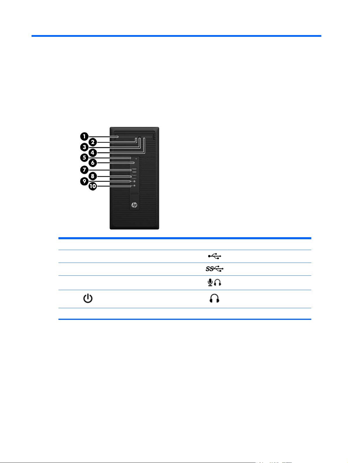
Front panel
1 Optical drive 6 Hard drive activity light
2 Optical drive activity light 7
3 Optical drive eject button 8
4 Optical drive emergency eject hole 9
5
* Software selectable mode, default mode is microphone.
Power button 10 Headphone connector
USB 2.0 port (2)
USB 3.0 ports (2)
Microphone-Headphone connector*
Workstation components 1
Page 12
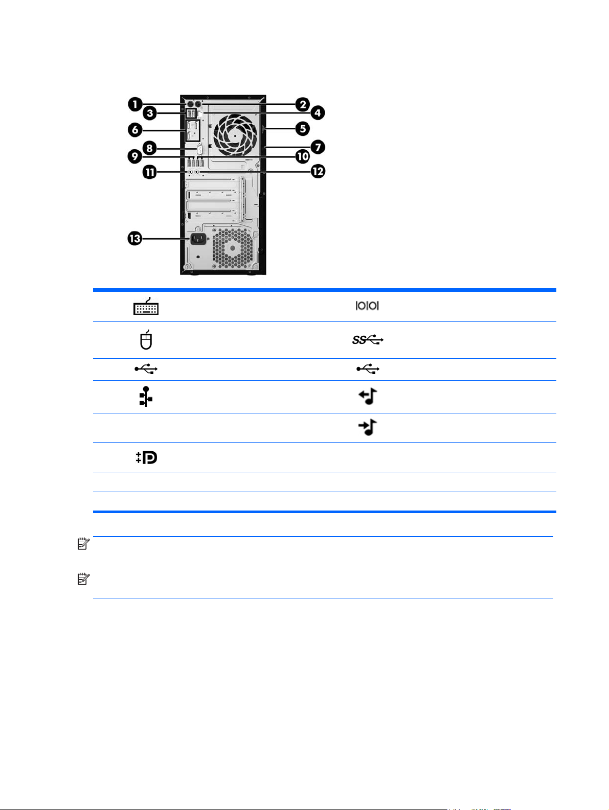
Rear panel
1 PS/2 keyboard connector 8 Serial port connector
2
3
4
5 Padlock loop 12
6
7 Cable lock slot
NOTE:
ports are disabled by default.
NOTE:
(f10) Setup Utility. However, HP recommends using only discrete graphics cards to drive three or more displays.
The DP ports are not supported when the system is configured with Intel Xeon E3-12x0 v3 processors. Also, if a discrete graphics card is installed these
Simultaneous usage of integrated Intel HD graphics and discrete graphics cards (in order to drive more than three displays) can be enabled using Computer
PS/2 mouse connector 9 USB 3.0 ports (2)
USB 2.0 ports (2) 10 USB 2.0 ports (2)
RJ-45 Ethernet connector 11 Audio line-out connector
Dual-Mode DisplayPort (3) 13 Power cord connector
NOTE: The labels for the rear panel connectors use industry-standard icons and colors.
Audio line-in connector
2 Chapter 1 Hardware overview
Page 13
Chassis components
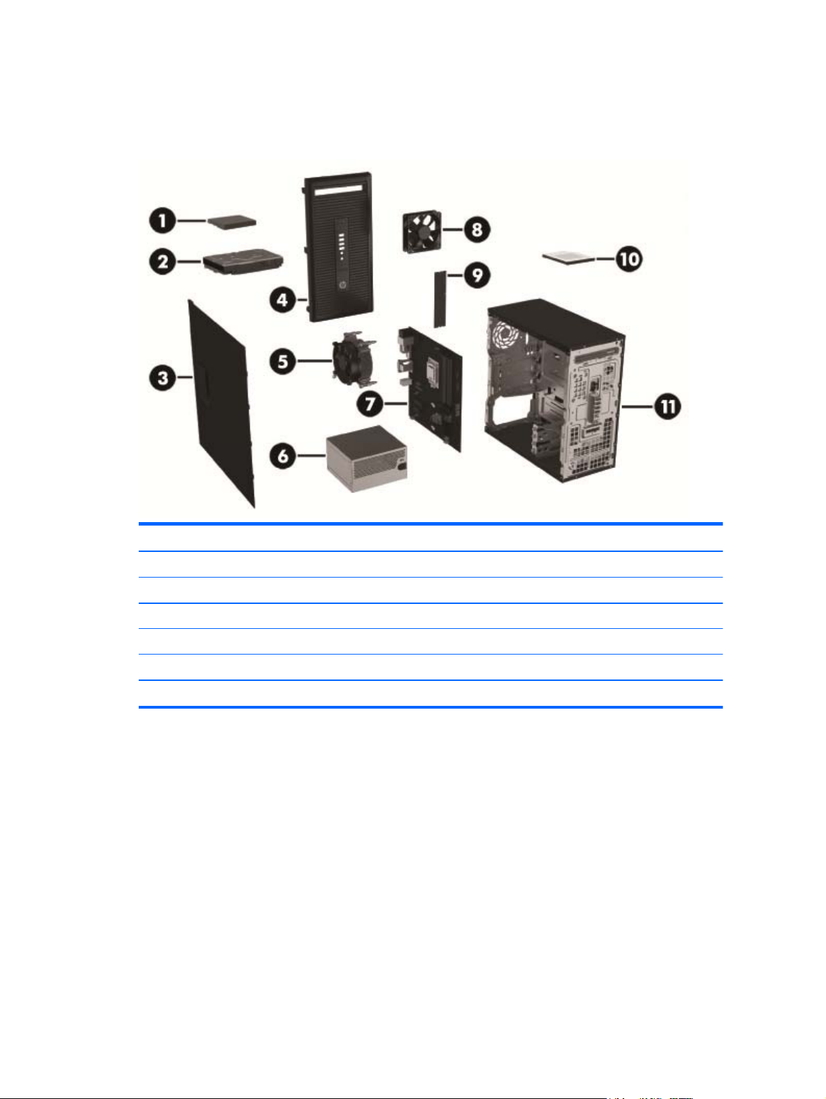
The following figure shows the chassis components of a typical tower workstation layout. Drive
configurations can vary.
Item Description Item Description
1 Solid-state drive (SSD) 7 System board
2 Hard drive (HDD) 8 System fan
3 Side access panel 9 Memory module
4 Front bezel 10 Slim optical drive
5 Heat sink fan 11 Chassis
6 Power supply
Workstation components 3
Page 14
System board components
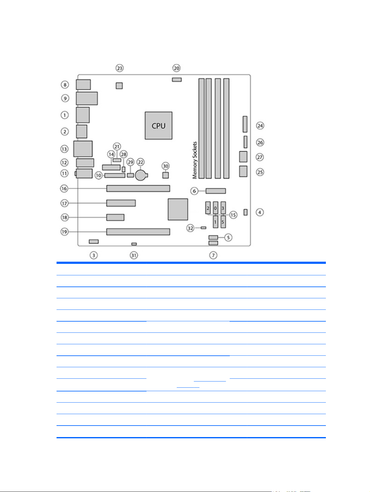
The following illustration and table identify the system board components for the tower workstation.
I/O SATA Power
1 Dual-Mode DisplayPort 15 AHCI 6Gb/s 22 Battery
2 DisplayPort 23 Processor
3 Front audio 24 Front power button/LED
4 Front speaker PCI/PCIe 25 Main power
5 Front USB 2.0 16 PCIe3 x16 26 Power COMM
6 Front USB 3.0 17 PCIe2 x4 (1) 27 SATA power
7 Internal USB 2.0 18 PCIe2 x1 Security
8 Keyboard / mouse 19 PCIe2 x16 (4) 28 Chassis solenoid lock
9 Network / rear USB 2.0 NOTE: For related expansion card
10 Parallel (option) Service
slot information, see
11 Rear audio Cooling 30 Clear CMOS button
12 Rear USB 2.0/3.0 20 Processor fan 31 ME/AMT flash override
13 Serial 21 Rear fan 32 Password jumper
14 Serial (option)
Expansion slots
on page 43
29 Hood sensor
4 Chapter 1 Hardware overview
Page 15
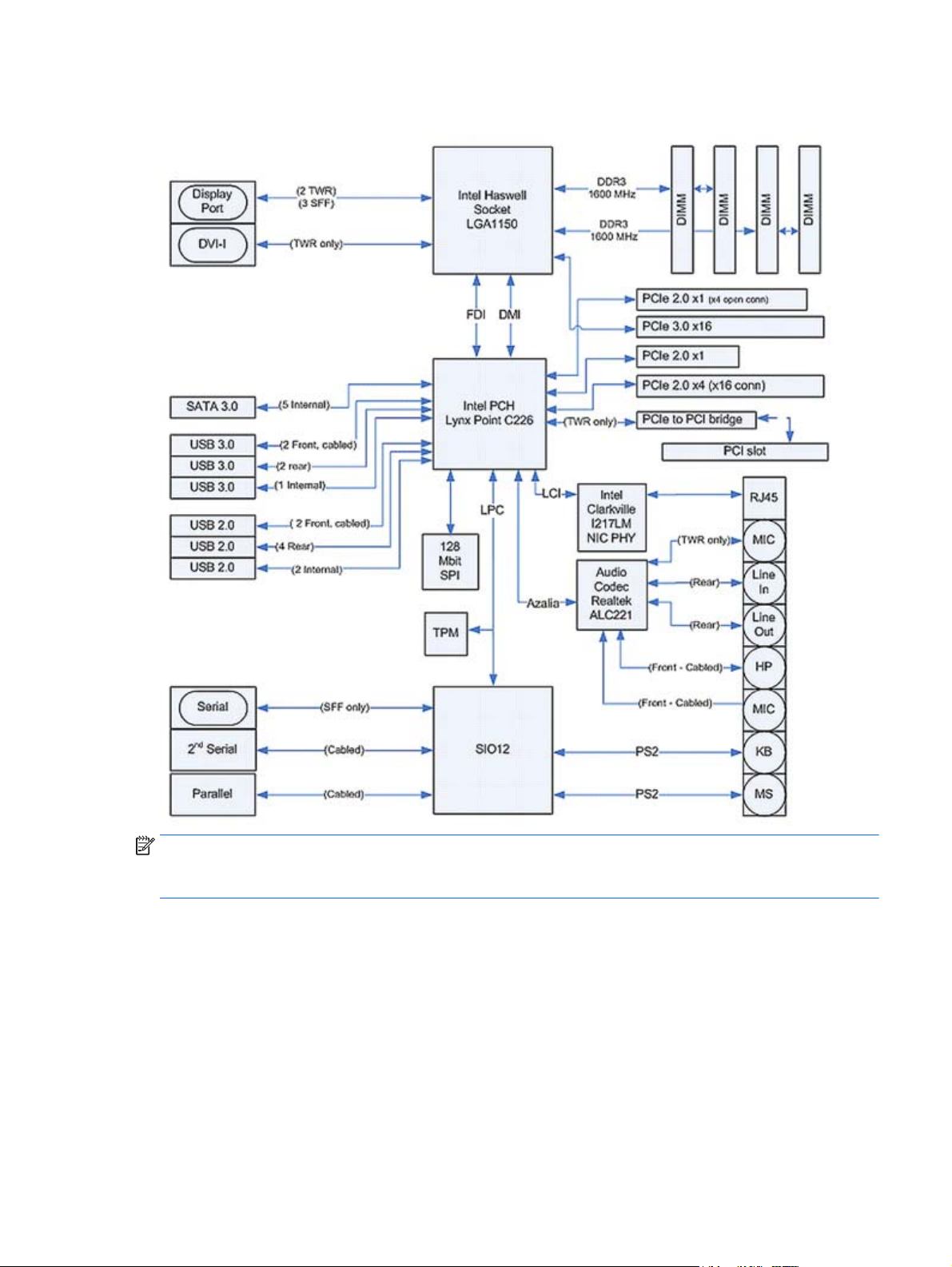
System board architecture
NOTE: The PCIe designators indicate the mechanical connector size and number of electrical PCIe lanes
routed to an expansion slot. For example, x16(4) means that the expansion slot is mechanically a x16 length
connector, with 4 PCIe lanes supported.
Workstation components 5
Page 16

Workstation specifications
Intel Series C226 chipset:
●
Support for the Intel Xeon Processor E3 v3 Family or third-generation Intel Core processors up to 95 W
●
Integrated 2-channel memory controller
Processor
technology
Power supply
Memory
technology
●
Microarchitecture improvements
●
Integrated graphics (some models)
●
Advanced Vector Extensions (AVX) to increase floating point performance
●
Intel DMI2 interface connecting the processor to the I/O controller
●
280 W, 90% efficient, 80 PLUS Gold, compatible with ENERGY STAR Version 5.2 requirements
●
Supports European Union ERP Lot 6 tier2 power limit of less than 0.5 W in off mode
●
Dual in-line memory modules (DIMMs) based on DDR3 1600MHz technology
●
Supports error checking and correcting (ECC) and non-ECC DIMMs
●
Two direct-attach memory channels enable low-latency access and fast data transfer for improved
performance
●
Up to 32 GB system memory (8 GB DIMMs)
●
1600 MHz 4, 8 GB ECC unbuffered DIMM
●
1600 MHz 4, 8 GB non ECC unbuffered DIMM
Graphics cards
I/O technology
Supports:
●
PCIe Gen3 (PCIe3) bus speeds; can support dual PCIe Gen2 graphics cards in mechanical PCIe x16 slots
●
Multiple graphics cards, provided their total power usage is within 75 W
●
Up to two displays with integrated Intel HD graphics (depending on processor type)
●
Up to six 2D displays or four 3D displays
NOTE: Most supported Intel Core processors provide Intel HD Graphics 4400/4600; Intel Xeon processors
with model designations that end in "---5" provide Intel HD Graphics P4600.
NOTE: To drive more than three displays, use Computer Setup (f10) Utility to intermix integrated Intel HD
graphics and discrete graphics cards.
●
RAID configurations for SATA RAID levels 0, 1
●
Supports eSATA (3.0 Gbps) using an optional adapter
●
Six external and two internal USB 2.0 ports
●
Four external USB 3.0 ports
●
Serial headers that can be used with an optional PCI bulkhead connector
6 Chapter 1 Hardware overview
Page 17

Product specifications
Workstation weights and dimensions
Standard configuration 7.0 kg (15.4 lb)
Weight
Chassis dimensions
Environmental specifications
Operating: 5°C to 35°C (40°F to 95°F)
Temperature
Humidity
Altitude
Shock
Non-operating: -40°C to 60°C (-40°F to 140°F)
NOTE: Derate by 1°C (1.8°F) for every 305 m (1,000 ft) altitude over 1,524 m (5,000 ft).
Operating: 8% to 85% relative humidity, non-condensing
Non-operating: 8% to 90% relative humidity, non-condensing
Operating: 0 to 3,048 m (10,000 ft)
Non-operating: 0 to 9,144 m (30,000 ft)
Operating: ½-sine: 40g, 2-3ms (~62 cm/s)
Non-operating:
●
½-sine: 160 cm/s, 2-3ms (~105g)
●
square: 422 cm/s, 20g
NOTE: Values represent individual shock events and do not indicate repetitive shock events.
Minimum configuration 6.8 kg (15.0 lb)
Maximum configuration 7.4 kg (16.3 lb)
Height 35.5 cm (14.0 in)
Width 17.0 cm (6.7 in)
Depth 35.8 cm (14.0 in)
Vibration
Operating Random: 0.5g (rms), 5-300 Hz, up to 0.0025g²/Hz
Non-Operating: random: 2.0g (rms), 5-500 Hz, up to 0.0150g²/Hz
NOTE: Values do not indicate continuous vibration.
Product specifications 7
Page 18
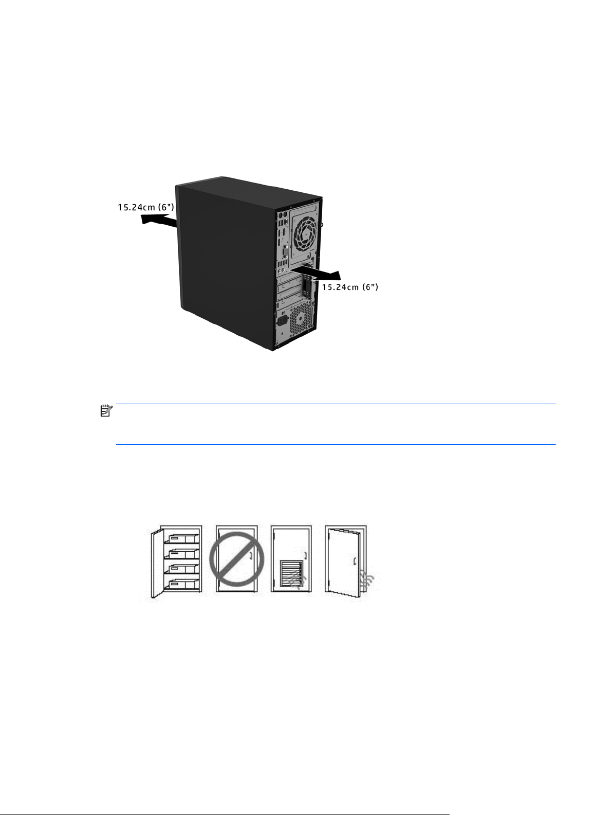
Ensuring proper ventilation
Proper ventilation for the system is important for workstation operation. Follow these guidelines:
●
Operate the workstation on a sturdy, level surface.
●
Provide at least 15.24 cm (6 inches) of clearance at the front and back of the workstation. (Workstation
models vary.)
●
Be sure that the ambient air temperature falls within the environmental specifications listed in this
document.
NOTE: The ambient upper limit of 35°C (95°F) is only good up to 1524 m (5000 ft) elevation. There is a
1°C (33.8°F) per 304.8 m (1000 ft) derating above 1524 m (5000 ft). So, at 3,048 m (10,000 ft), the
upper ambient air temperature limit is 30°C (86°F).
●
For cabinet installation, be sure that adequate cabinet ventilation and the ambient temperature within
the cabinet does not exceed specified limits.
●
Never restrict the incoming or outgoing airflow of the workstation by blocking any vents or air intakes,
as shown in the following figure.
8 Chapter 1 Hardware overview
Page 19

2 System management
This section describes the tools and utilities that provide system management for the workstation.
Topics
Power management and performance features on page 9
BIOS ROM on page 10
Computer Setup (f10) Utility on page 10
Desktop management on page 23
Power management and performance features
ERP compliance mode
This computer provides ERP compliance mode capability.
When enabled, the computer shuts down to the lowest possible power state. The computer must then be
turned on with the power button. One of the effects is that "wake on LAN" is disabled.
When disabled, the computer powers down conventionally.
1. Press f10 during startup.
2. Using the arrow keys, select the Power > Hardware Power Management > S5 Maximum
Power Savings, then select Enable.
3. Press f10 to accept the change.
Enabling ERP compliance mode
Disabling ERP compliance
mode
4. Select File > Save Change and Exit, and then press enter to accept the change.
5. If using Windows 8 or Windows 8.1, boot to Windows and search in the Start Menu for the
setting Change what the power buttons do. Uncheck Turn on fast startup (recommended).
If the checkbox is not available, select Change settings that are currently unavailable at the
top of the window.
1. Press f10 during startup.
2. Using the arrow keys, select Power > Hardware Power Management > S5 Maximum Power
Savings, then select Disable.
3. Press f10 to accept the change.
4. Select File > Save Change and Exit, and then press enter to accept the change.
5. If using Windows 8 or Windows 8.1, boot to Windows and search in the Start Menu for the
setting Change what the power buttons do. Check Turn on fast startup (recommended). If
the checkbox is not available, select Change settings that are currently unavailable at the
top of the window.
Power management and performance features 9
Page 20

Hyper-Threading Technology (HTT)
This computer supports HTT, an Intel-proprietary technology that improves processor performance through
parallelization of computations (doing multiple tasks at once).
The operating system treats an HTT-enabled processor as two virtual processors, and shares the workload
between them when possible. This feature requires that the operating system support multiple processors
and be specifically optimized for HTT.
Use Computer Setup (f10) Utility to enable HTT.
Go to
http://www.hp.com/go/quickspecs to determine if your CPU supports HTT.
SATA Power Management
SATA Power Management enables or disables SATA bus and/or device power management.
Intel Turbo Boost Technology
Your workstation supports Intel® Turbo Boost Technology.
This feature enables the CPU to run at a higher than normal rate. When all CPU cores are not necessary for
the workload, inactive cores are turned off and power is diverted to the active cores to increase their
performance.
Turbo Boost is enabled and disabled with Computer Setup (f10) Utility.
http://www.hp.com/go/quickspecs to determine if your CPU supports Turbo Boost.
Go to
BIOS ROM
The BIOS ROM is a collection of machine language applications stored as firmware in ROM. It includes
functions such as Power-On Self-Test (POST), PCI device initialization, Plug and Play support, power
management, and Computer Setup (f10) Utility.
http://www.hp.com/go/quickspecs to review the latest BIOS ROM specifications.
Go to
Computer Setup (f10) Utility
Use Computer Setup (f10) Utility to do the following:
●
Change factory default settings.
●
Set the system date and time.
●
Set, view, change, or verify the system configuration, including settings for processor, graphics,
memory, audio, storage, communications, and input devices.
●
Modify the boot order of bootable devices such as hard drives, optical drives, or USB flash media
devices.
●
Select Post Messages Enabled or Disabled to change the display status of Power-On Self-Test (POST)
messages. Post Messages Disabled suppresses most POST messages, such as product name, and other
non-error text messages. If a POST error occurs, the error is displayed regardless of the mode selected.
To manually switch to Post Messages Enabled during POST, press any key (except f1 through f12).
●
Establish an Ownership Tag, the text of which is displayed each time the system is turned on or
restarted.
●
Enter the Asset Tag or property identification number assigned by the company to this computer.
10 Chapter 2 System management
Page 21

●
Enable the power-on password prompt during system restarts (warm boots) as well as during poweron.
●
Establish a setup password that controls access to Computer Setup (f10) Utility and the settings
described in this section.
●
Secure integrated I/O functionality, including the serial or USB ports, audio, or embedded NIC, so that
they cannot be used until they are unsecured.
●
Enable or disable removable media boot ability.
●
Solve system configuration errors detected but not automatically fixed during the Power-On Self-Test
(POST).
●
Replicate the system setup by saving system configuration information on a USB device and restoring it
on one or more computers.
●
Execute self-tests on a specified ATA hard drive (when supported by drive).
●
Enable or disable DriveLock security (when supported by drive).
Computer Setup (f10) Utility 11
Page 22
Using Computer Setup (f10) Utility
To start Computer Setup (f10) Utility, complete the following steps:
1. Turn on or restart the computer.
2. Repeatedly press f10 when the monitor light turns green.
NOTE: If you do not press f10 at the appropriate time, you must restart the computer and again
repeatedly press f10 when the monitor light turns green.
3. A choice of five headings appears in the Computer Setup (f10) Utility menu: File, Storage, Security,
Power, and Advanced.
4. Use the arrow (left and right) keys to select the appropriate heading. Use the arrow (up and down) keys
to select the option you want, then press enter. To return to the Computer Setup (f10) Utility menu,
press esc.
5. To apply and save changes, select File > Save Changes and Exit.
●
If you have made changes that you do not want applied, select Ignore Changes and Exit.
●
To reset to factory settings or previously saved default settings (some models), select Apply
Defaults and Exit. This option will restore the original factory system defaults.
NOTE: Not all settings shown in the following sections are available for all models
CAUTION: Do NOT turn the computer power OFF while the BIOS is saving Computer Setup (f10) Utility
changes because the CMOS might become corrupted. It is safe to turn off the computer only after exiting
Computer Setup (f10) Utility screen.
Heading Table
File
Storage
Security
Power
Advanced
Computer Setup (f10) Utility—File on page 13
Computer Setup (f10) Utility—Storage on page 14
Computer Setup (f10) Utility—Security on page 16
Computer Setup—Power on page 19
Computer Setup—Advanced on page 20
12 Chapter 2 System management
Page 23

Computer Setup (f10) Utility—File
NOTE: Support for specific Computer Setup (f10) Utility options might vary depending on the hardware
configuration.
Option Description
System Information Lists:
●
Product name
●
Manufacturer
●
SKU number
●
Processor type/speed/stepping
●
Memory Size (Channel A, Channel B) Installed memory size/speed, number of channels (single or
dual) (if applicable)
●
Integrated MAC address for embedded, enabled NIC (if applicable)
●
Chassis serial number
●
Asset tracking number
●
System Board ID
●
System Board CT Number
●
System BIOS (includes family name, version, and date)
●
ME firmware version
About Displays copyright notice.
Set Time and Date Allows you to set system time and date.
Flash System ROM Allows you to update the system ROM with a BIOS image file located on removable media.
Replicated Setup Save to Removable Media
Saves system configuration to a formatted USB flash media device.
Restore from Removable Media
Restores system configuration from a USB flash media device.
Default Setup Save Current Settings as Default
Saves the current system configuration settings as the default.
Restore Factory Settings as Default
Restores the factory system configuration settings as the default.
Apply Defaults and Exit Applies the currently selected default settings and clears any established passwords.
Ignore Changes and Exit Exits Computer Setup (f10) Utility without applying or saving any changes.
Save Changes and Exit Saves changes to system configuration or default settings and exits Computer Setup (f10) Utility.
Computer Setup (f10) Utility 13
Page 24

Computer Setup (f10) Utility—Storage
NOTE: Support for specific Computer Setup (f10) Utility options may vary depending on the hardware
configuration.
Option Description
Device Configuration Lists all installed BIOS-controlled storage devices.
When a device is selected, detailed information and options are displayed. The following options might be
presented:
●
Hard Drive: Size, model, firmware version, serial number, connector color.
Translation mode (ATA disks only)
Lets you select the translation mode to be used for the device. This enables the BIOS to access disks
partitioned and formatted on other systems and may be necessary for users of older versions of
UNIX (e.g., SCO UNIX version 3.2). Options are Automatic, Bit-Shift, LBA Assisted, User, and Off.
Available only when the drive translation mode is set to User, allows you to specify the parameters
(logical cylinders, heads, and sectors per track) used by the BIOS to translate disk I/O requests (from
the operating system or an application) into terms the hard drive can accept. Logical cylinders may
not exceed 1024. The number of heads may not exceed 256. The number of sectors per track may
not exceed 63.
CAUTION: Ordinarily, the translation mode selected automatically by the BIOS should not be
changed. If the selected translation mode is not compatible with the translation mode that was
active when the disk was partitioned and formatted, the data on the disk will be inaccessible.
●
CD-ROM: Model, firmware version, serial number, connector color (not included for USB CD-ROM).
●
SSD Life Used
NOTE: Displays for solid-state drives.
●
SMART (ATA disks only)
●
Diskette: Model and firmware version.
NOTE: Displays for USB diskette drives.
●
Default Values (ATA disks only)
See Translation Mode above for details.
SATA Defaults
Storage Options eSATA Port
Allows you to set a SATA port as an eSATA port for use with an external drive. Default is enabled.
This setting affects only the port with the black connector, labeled as eSATA on the system board. This
port should have the eSATA back panel connector attached to use eSATA drives. For more information,
see the eSATA white paper at
SATA Emulation
Allows you to choose how the SATA controller and devices are accessed by the operating system. There
are three supported options.
CAUTION: SATA emulation changes may prevent access to existing hard drive data and degrade or
corrupt established volumes.
IDE—Is the most backward-compatible setting of the three options. Operating systems usually do not
require additional driver support in IDE mode.
RAID (default option)—Allows DOS and boot access to RAID volumes. Use this mode with the RAID device
driver loaded in the operating system to take advantage of RAID features.
www.hp.com.
14 Chapter 2 System management
Page 25

AHCI—Allows operating systems with AHCI device drivers loaded to take advantage of more advanced
features of the SATA controller.
NOTE: The RAID/AHCI device driver must be installed prior to attempting to boot from a RAID/AHCI
volume. If you attempt to boot from a RAID/AHCI volume without the required device driver installed, the
system will crash (blue screen). RAID volumes may become corrupted if they are booted to after disabling
RAID.
Removable Media Boot
Enables/disables ability to boot the system from removable media. Default is enabled.
Max eSATA Speed
Allows you to choose 1.5 Gbps or 3.0 Gpbs as the maximum eSATA speed. By default, the speed is limited
to 1.5 Gbps for maximum reliability.
CAUTION: Consult your eSATA drive and cable manufacturer before enabling 3.0 Gpbs speed. Some
drive and cable combinations may not run reliably at 3.0 Gpbs.
Boot Order Allows you to:
●
UEFI Boot Sources: Specify the order in which UEFI boot sources (such as a internal hard drive, USB
hard drive, USB optical drive, or internal optical drive) are checked for a bootable operating system
image. Each device on the list may be individually excluded from or included for consideration as a
bootable operating system source.
UEFI boot sources always have precedence over legacy boot sources.
●
Legacy Boot Sources: Specify the order in which legacy boot sources (such as a network interface
card, internal hard drive, USB optical drive, or internal optical drive) are checked for a bootable
operating system image. Each device on the list may be individually excluded from or included for
consideration as a bootable operating system source.
Specify the order of attached hard drives. The first hard drive in the order will have priority in the
boot sequence and will be recognized as drive C (if any devices are attached).
Shortcut to Temporarily Override Boot Order
To boot one time from a device other than the default device specified in Boot Order, restart the
computer and press esc (to access the boot menu) and then f9 (Boot Order), or press f9 (bypassing the
boot menu) when the monitor light turns green. After POST is completed, a list of bootable devices is
displayed. Use the arrow keys to select the preferred bootable device and press enter. The computer then
boots from the selected non-default device for this one time.
Computer Setup (f10) Utility 15
Page 26

Computer Setup (f10) Utility—Security
NOTE: Support for specific Computer Setup (f10) Utility options may vary depending on the hardware
configuration.
Option Description
Setup Password Allows you to set and enable a setup (administrator) password.
NOTE: If the setup password is set, you must enter it to change Computer Setup (f10) Utility options,
flash the ROM, and make changes to certain plug and play settings under Windows.
Power-On Password Allows you to set and enable a power-on password. The power-on password prompt appears after a
power cycle or reboot. If the user does not enter the correct power-on password, the unit will not boot.
Password Options
(This selection appears
only if a power-on
password or setup
password is set.)
Smart Cover
(This selection appears
only if a hood sensor is
installed)
Allows you to enable/disable:
●
Lock Legacy Resources (determines whether or not Windows Device Manager is allowed to change
resource settings for serial and parallel ports).
●
Stringent security (enabling the stringent password disables the ability to reset the password by
moving the jumper on the system board). Default is disabled.
CAUTION: If you enable the stringent security feature and you forget the setup password or the
power-on password, the computer is inaccessible and can no longer be used.
If you lose or forget the password, the system board must be replaced. This scenario is not covered
under warranty.
To prevent the computer from becoming permanently unusable, record your configured setup
password or power-on password in a safe place away from your computer. Without these
passwords, the computer cannot be unlocked.
●
Setup Browse Mode (appears if a setup password is set) (allows viewing, but not changing,
Computer Setup (f10) Utility Options without entering setup password). Default is enabled.
●
Password prompt on f9, f11, and f12 (requires setup password to use these boot functions). Default
is enabled.
●
Network Server Mode. Default is disabled.
Allows you to:
●
Lock/unlock the Cover Lock.
●
Set the Cover Removal Sensor to Disable/Notify User/Setup Password.
NOTE: Notify User alerts the user that the sensor has detected that the cover has been removed. Setup
Password requires that the setup password be entered to boot the computer if the sensor detects that
the cover has been removed.
Device Security Allows you to set Device Available/Device Hidden (default is Device Available) for:
USB Security Allows you to set Enabled/Disabled (default is Enabled) for:
16 Chapter 2 System management
●
Embedded security device
●
System audio
●
USB controller (varies by model)
●
Network controller
NOTE: You must disable AMT before trying to hide the network controller.
●
Parallel port
●
SATA ports (varies by model)
●
Front USB Ports
Page 27

●
Rear USB Ports
●
Accessory USB Ports
Slot Security Allows you to Enable/Disable Option ROM Download for each slot. Selective disabling of Option ROM
Network Boot Enables/disables the computer’s ability to boot from an operating system installed on a network server.
System IDs Allows you to set:
Master Boot Record
Security
downloads can help manage limited Option ROM space. Limit PCIe Frequency to Gen1, Gen2, Gen3. Runs
slot at Gen1, Gen2, or Gen3 frequency.
(Feature available on NIC models only; the network controller must be either a PCI expansion card or
embedded on the system board.) Default is enabled.
●
Asset tag (18-byte identifier), a property identification number assigned by the company to the
computer.
●
Ownership tag (80-byte identifier) displayed during POST.
●
Universal Unique Identifier (UUID) number. The UUID can only be updated if the current chassis
serial number is invalid. (These ID numbers are normally set in the factory and are used to uniquely
identify the system.)
●
Keyboard locale setting for System ID entry.
Enables/disables Master Boot Record (MBR) security.
The MBR contains information needed to successfully boot from a disk and to access the data stored on
the disk. Master Boot Record Security may prevent unintentional or malicious changes to the MBR, such
as those caused by some viruses or by the incorrect use of certain disk utilities. It also allows you to
recover the "last known good" MBR, should changes to the MBR be detected when the system is
restarted.
When MBR Security is enabled, the BIOS prevents any changes being made to the MBR of the current
bootable disk while in MS-DOS or Windows Safe Mode.
NOTE: Most operating systems control access to the MBR of the current bootable disk; the BIOS cannot
prevent changes that may occur while the operating system is running.
Restores the backup Master Boot Record to the current bootable disk. Default is disabled.
System Security (these
options are hardware
dependent)
Only appears if all of the following conditions are true:
●
MBR security is enabled
●
A backup copy of the MBR has been previously saved
●
The current bootable disk is the same disk from which the backup copy was saved
CAUTION: Restoring a previously saved MBR after a disk utility or operating system has modified the
MBR, may cause the data on the disk to become inaccessible. Only restore a previously saved MBR if you
are confident that the current bootable disk MBR has been corrupted or infected with a virus.
●
Data Execution Prevention—(Enable/Disable). Helps prevent operating system security breaches.
Default is enabled.
●
SVM CPU Virtualization—(Enable/Disable). Controls the virtualization features of the processor.
Changing this setting requires hat you turn off the computer and then turn it back on. Default is
disabled.
●
Virtualization Technology (VTx)—(Enable/Disable). Controls the virtualization features of the
processor. Changing this setting requires that you turn off the computer and then turn it back on.
Default is disabled.
●
Virtualization Technology Directed I/O (VTd)— (Enable/Disable). Controls virtualization DMA
remapping features of the chipset. Changing this setting requires that you turn off the computer
and then turn it back on. Default is disabled.
●
Trusted Execution Technology—(Enable/Disable). Controls the underlying processor and chipset
features needed to support a virtual appliance. Changing this setting requires that you turn off the
Computer Setup (f10) Utility 17
Page 28

computer and then turn it back on. Default is disabled. To enable this feature you must enable the
following features:
◦
Embedded Security Device Support
◦
Virtualization Technology
◦
Virtualization Technology Directed I/O
●
Embedded Security Device—(Enable/Disable). Permits activation and deactivation of the Embedded
Security Device.
NOTE: To configure the Embedded Security Device, a setup password must be set.
●
Reset to Factory Settings (Do not reset/Reset)—Resetting to factory defaults erases all security
keys and leaves the device in a disabled state. Changing this setting requires that you restart the
computer. Default is Do not reset.
CAUTION: The embedded security device is a critical component of many security schemes.
Erasing the security keys will prevent access to data protected by the Embedded Security Device.
Choosing Reset to Factory Settings may result in significant data loss.
●
Measure boot variables/devices to PCR1—Typically, the computer measures the boot path and
saves collected metrics to PCR5 (a register in the Embedded Security Device). Bitlocker tracks
changes to any of these metrics and forces the user to re-authenticate if it detects any changes.
Enabling this feature lets you set Bitlocker to ignore detected changes to boot path metrics, thereby
avoiding re-authentication issues associated with USB keys inserted in a port. Default is enabled.
System Security
(continued)
DriveLock Security Allows you to assign or modify a master or user password for hard drives. When this feature is enabled,
Secure Boot
Configuration
OS management of Embedded Security Device—(Enable/Disable). This option allows the user to limit OS
control of the Embedded Security Device. Default is enabled. This option is automatically disabled if
Trusted Execution Technology is enabled.
●
Reset of Embedded Security Device through OS—(Enable/Disable). This option allows the user to
limit the operating system ability to request a Reset to Factory Settings of the Embedded Security
Device. Default is disabled.
NOTE: To enable this option, a Setup password must be set.
●
No PPI provisioning (Windows 8 only)—This option lets you set Windows 8 to bypass the PPI
(Physical Presence Interface) requirement and directly enable and take ownership of the TPM on
first boot. You cannot change this setting after TPM is owned/initialized, unless the TPM is reset.
Default is disabled for systems other than Windows 8, and enabled for Windows 8.
●
Allow PPI policy to be changed by OS. Enabling this option allows the operating system to execute
TPM operations without Physical Presence Interface. Default is disabled.
NOTE: To enable this option, a Setup password must be set.
the user is prompted to provide one of the DriveLock passwords during POST. If neither is successfully
entered, the hard drive will remain inaccessible until one of the passwords is successfully provided during
a subsequent cold-boot sequence.
NOTE: This selection will only appear when at least one drive that supports the DriveLock feature is
attached to the system.
●
Legacy Support—Enable/Disable. Allows you to turn off all legacy support on the computer,
including booting to DOS, running legacy graphics cards, booting to legacy devices, and so on. If set
to disable, legacy boot options in Storage > Boot Order are not displayed. Default is enabled.
●
Secure Boot—Enable/Disable. Allows you to make sure an operating system is legitimate before
booting to it, making Windows resistant to malicious modification from preboot to full OS booting,
preventing firmware attacks. UEFI and Windows Secure Boot only allow code signed by preapproved digital certificates to run during the firmware and OS boot process. Default is disabled,
except for Windows 8 systems which have this setting enabled. Secure Boot enabled also sets
Legacy Support to disabled.
●
Key Management—This option lets you manage the custom key settings.
18 Chapter 2 System management
Page 29

Computer Setup—Power
NOTE: Support for specific Computer Setup Power options might vary depending on the hardware
configuration.
Option Description
◦
Clear Secure Boot Keys—Don't Clear/Clear. Allows you to delete any previously loaded custom
boot keys. Default is Don't Clear.
◦
Key Ownership—HP Keys/Custom Keys. Selecting Custom Mode allows you to modify the
contents of the secure boot signature databases and the platform key (PK) that verifies
kernels during system start up, allowing you to use alternative operating systems. Selecting
HP Keys causes the computer boot using the preloaded HP-specific boot keys. Default is HP
Keys.
●
Fast Boot—Enable/Disable. Fast boot disables the ability to interrupt boot, such as pressing f keys
to access items before the operating system loads. Default is disabled.
NOTE: If Windows 8 detects a serious error, it will interrupt the boot process automatically and
display advanced boot options.
From the Start screen, you can press shift and select Restart to boot to a device or troubleshoot
your computer.
OS Power Management
Hardware Power
Management
●
Runtime Power Management—Enable/Disable. Allows certain operating systems to reduce
processor voltage and frequency when the current software load does not require the full
capabilities of the processor. Default is enabled.
●
Idle Power Savings—Extended/Normal. Allows certain operating systems to decrease the
processor's power consumption when the processor is idle. Default is extended.
●
ACPI S3 PS2 Mouse Wake Up—Enable/Disable: Enables or disables waking from S3 due to any PS2
mouse activity or a button click.
●
Unique Sleep State Blink Rates—Enable/Disable. This feature is designed to provide a visual
indication of what sleep state the system is in. Each sleep state has a unique blink pattern. Default
is disabled.
NOTE: For Windows 8 systems with Fast Boot support, a normal shutdown goes to the S4 state,
not the S5 state.
◦
S0 (On)—Solid green LED.
◦
S3 (Stand By)—3 blinks at 1Hz (50% duty cycle) followed by a pause of 2 seconds. (green LED)
—Repeated cycles of 3 blinks and a pause.
◦
S4 (Hibernation)—4 blinks at 1Hz (50% duty cycle) followed by a pause of 2 seconds. (green
LED)—Repeated cycles of 4 blinks and a pause.
◦
S5 (Soft Off)—LED is off.
●
SATA Power Management—Enables or disables SATA bus and/or device power management.
Default is enabled.
●
S5 Maximum Power Savings—Turns off power to all nonessential hardware when system is off to
meet EUP Lot 6 requirement of less than 0.5 Watt power usage. Default is disabled.
Thermal Fan idle mode—This bar graph controls the minimum permitted fan speed.
NOTE: This setting only changes the minimum fan speed. The fans are still automatically controlled.
Computer Setup (f10) Utility 19
Page 30

Computer Setup—Advanced
NOTE: Support for specific Computer Setup options may vary depending on the hardware configuration.
Option Heading
Power-On Options Allows you to set:
●
●
●
●
NOTE: If you turn off the computer using the switch on a power strip, you will not be able to use the
suspend/sleep feature or the Remote Management features.
●
●
●
●
POST messages—(Enable/Disable). This feature causes the system to display POST error messages,
which are error messages displayed on the monitor during the Power-On Self-Test if the BIOS
encounters some kind of problem while starting the computer. A POST error message will display on
screen only if the computer is capable of booting this far. If the POST detects an error before this
point, a beep code is generated instead. Default is disabled.
Press the esc key for Startup Menu—(Enable/Disable). This feature controls the display of the text
“Press the esc key for Startup Menu” during POST. Neither this text nor any other (for example, the
Ownership Tag) is displayed on Windows 8 systems that have Fast Boot support.
Option ROM Prompt—(Enable/Disable). This feature causes the system to display a message before
loading option ROMs. Default is enabled.
After Power Loss—(off/on/previous state). Default is Power off. Setting this option to:
◦
Power off—Causes the computer to remain powered off when power is restored.
◦
Power on—Causes the computer to turn on automatically as soon as power is restored.
◦
Previous state—Causes the computer to turn on automatically as soon as power is restored, if
it was on when power was lost.
POST Delay (in seconds). This feature adds a user-specified delay to the POST process. This delay is
sometimes needed for hard drives that spin up so slowly that they are not ready to boot by the time
POST is finished. The POST delay also gives you more time to select f10 to enter Computer Setup
(f10) Utility. Default is None.
Remote Wakeup Boot Source (remote server/local hard drive). Default is Local hard drive.
Factory Recovery Boot Support—(Enable/Disable). This feature enables the BIOS to redirect the
boot to a recovery partition on the user hard drive, if one is present. Some versions of the recovery
software honor the f11 key press even when this feature is disabled. Default is disabled.
Bypass f1 Prompt on Configuration Changes— (Enable/Disable). Allows you bypass the
confirmation step after changes are made. Default is enabled.
BIOS Power-On This feature enables you to specify a time for the computer to start automatically.
Onboard Devices Allows you to set resources for or disable Legacy devices.
Bus Options Allows you to enable or disable:
Device Options Allows you to set:
20 Chapter 2 System management
Select the Legacy device's IRQ, DMA, and I/O Range. The settings may not take effect for all operating
systems. To hide a device from the operating system, see Security > Device Security.
●
PCI SERR# Generation—(Enable/Disable) Default is enabled.
●
PCI VGA Palette Snooping—(Enable/Disable) Sets the VGA palette snooping bit in PCI configuration
space; only needed when more than one graphics controller is installed. Default is disabled.
●
PCI Latency Timer—Sets PCI Clock speed. (32/64/96/128/160/192/224/248). 128 PCI Clocks is the
default.
●
Turbo Mode—(Enable/Disable). Allows you to enable and disable the Intel Turbo Mode feature,
which allows one core of the system to run at a higher than standard frequency and power if other
cores are idle. Default is enabled.
Page 31

●
S5 Wake on LAN—(Enable or Disable)
●
Num Lock State at Power-On—(On or Off). Default is off.
●
IGD Memory—(32, 64, 128, 256, 512, 1024) Controls how much system RAM is reserved for use by
the internal graphics device. The value you choose is allocated permanently to graphics and is
unavailable to the operating system. For example, if you set this value to 512M on a system with 2
GB of RAM, the system always allocates 512 MB for graphics and the other 1.5 GB for use by the
BIOS and operating system.
●
Integrated Video (Enable/Disable). Use this option to disable the integrated video controller when
another video controller is present in the system. Default is enabled.
●
Internal Speaker (does not affect external speakers)—(Enable/Disable). Default is enabled.
●
USB EHCI Port Debug—(Enable/Disable)
●
Multi-Processor—(Enable/Disable). Use this option to disable multi-processor support under the
OS. Default is enabled.
●
Hyper threading—(Enable/Disable). Use this option to disable processor hyper-threading.
Slot Settings Lets you Enable/Disable Option ROM Download for each slot. Selective disabling of Option ROM
VGA Configuration Displayed only if there is an add-in video card in the system. Allows you to specify which VGA controller
Management Operations Allows you to set:
Option ROM Launch
Policy
downloads can help manage limited Option ROM space. Limit PCIe Frequency to Gen1, Gen2, Gen3. Runs
slot at Gen1, Gen2, or Gen3 frequency.
will be the “boot” or primary VGA controller.
●
AMT—(Enable/Disable). Allows you to enable or disable functions of the embedded Management
Engine (ME) such as Active Management Technology (AMT). If set to disable, the Management
Engine is set to a temporarily disabled state and will not provide functions beyond necessary
system configuration. Default is enabled.
●
Unconfigure AMT/ME—(Enable/Disable). Allows you to unconfigure any provisioned management
settings for AMT. The AMT settings are restored to factory defaults. This feature should be used
with caution as AMT will not be able to provide any set AMT management functions once
unconfigured. Default is disabled.
●
Hide Unconfigure ME Confirmation Prompt—(Enable/Disable). Allows you to set the system to not
display the confirmation to unconfigure ME.
●
Watchdog Timer—(Enable/Disable). Allows you to set amount of time for an operating system and
BIOS watchdog alert to be sent if the timers are not deactivated. BIOS watchdog is deactivated by
BIOS and would indicate that a halt occurred during execution if the alert is sent to the management
console. An operating system alert is deactivated by the operating system image and would indicate
that a hang occurred during its initialization. Default is enabled.
●
PXE Option ROMs—(Legacy, UEFI Only/Do Not Launch)
●
StorageOption ROMs—(Legacy, UEFI Only/Do Not Launch)
●
Video Options—(Legacy, UEFI Only)
Connected BIOS
Update BIOS via Network
Intel Ethernet
Connection
●
Connected BIOS—(Enable/Disable)
●
Use Proxy—(Enable/Disable)
●
Update BIOS via Network—(Enable/Disable)
●
Update Source
●
Automatic BIOS Update Setting—(Enable/Disable)
●
Port Configuration Menu
◦
UEFI Driver
◦
Adapter PBA
Computer Setup (f10) Utility 21
Page 32

◦
Chip Type
◦
PCI Device ID
◦
PCI Bus:Device:Function
◦
Link Status—(Enable/Disable)
◦
Factory MAC Address
●
NIC Configuration
◦
Link Speed
◦
Wake on LAN—(Enable/Disable)
●
Blink LEDs—(Range 0–15 seconds)
22 Chapter 2 System management
Page 33

Desktop management
This section summarizes capabilities, features, and key components of computer management.
Topics
Initial computer configuration and deployment on page 24
Installing a remote system on page 24
Copying a setup configuration to another computer on page 24
Updating and managing software on page 25
HP Client Management Solutions on page 25
Altiris Client Management Solutions on page 25
HP SoftPaq Download Manager on page 26
System Software Manager on page 26
ROM Flash on page 26
FailSafe Boot Block on page 26
Workstation security on page 27
Fault notification and recovery on page 34
Programmable power button (Windows only) on page 34
NOTE: Support for specific features described in this guide can vary by model and software version.
Desktop management 23
Page 34

Initial computer configuration and deployment
The computer includes a preinstalled system software image. After a brief software unbundling process, the
computer is ready to use.
If you prefer to replace the preinstalled software image with a customized set of system and application
software, you can deploy a customized software image by:
●
Installing additional software applications after unbundling the preinstalled software image
●
Using a disk-cloning process to copy the contents from one hard drive to another
The HDD-based HP Recovery Manager ROM-based setup, and ACPI hardware provide further assistance with
recovery of system software, configuration management and troubleshooting, and power management.
Support for specific features described in this guide can vary by model and software version.
The best deployment method depends on the information technology environment and processes.
Installing a remote system
Remote system installation enables starting and setting up the computer using software and configuration
information on a network server. This feature is usually used for system setup and configuration and can be
used to:
●
Deploy a software image on new PCs
●
Format a hard drive
●
Install application software or drivers
●
Update the operating system, application software, or drivers
To initiate a remote system installation, press f12 when f12=Network Service Boot appears in the lowerright corner of the HP logo screen. Follow the on-screen instructions to continue the installation process. The
default boot order is a BIOS configuration setting that can be changed to always attempt a network boot.
Copying a setup configuration to another computer
This section provides information about replicating the computer setup.
CAUTION: Setup configuration is model-specific. File system corruption can result if source and target
computers are not the same model.
To copy a setup configuration:
1. Select a setup configuration to copy, and then restart the computer.
2. As soon as you start or restart the computer, press and hold f10 until you enter Computer Setup (f10)
Utility. If necessary, press enter to bypass the title screen.
NOTE: If you do not press f10 at the appropriate time, you must restart the computer, and then press
and hold f10 again to access the utility.
If you are using a PS/2 keyboard, you might see a keyboard error message. Disregard it.
3. Select File > Replicated Setup > Save to Removable Storage Device. Follow the instructions on the
screen to create the configuration file cpqsetup.txt and write it to a USB storage device.
4. Turn off the computer you are configuring and insert the removable USB media device containing the
configuration file.
24 Chapter 2 System management
Page 35

5. Turn on the computer you are configuring.
6. Press and hold the f10 key until you enter Computer Setup (f10) Utility. If necessary, press enter to
bypass the title screen.
7. Select File > Replicated Setup > Restore from Removable Storage Device, and then follow the
instructions on the screen.
8. Restart the computer when the configuration is complete.
Updating and managing software
HP provides several tools for managing and updating software on desktops and computers:
●
HP Client Manager Software
●
Altiris Client Management Solutions
●
HP SoftPaq Download Manager
●
System Software Manager
HP Client Management Solutions
HP Client Management Solutions (CMS), available for download from http://www.hp.com/go/easydeploy, are
standards-based solutions for managing and controlling computers in a networked environment.
HP Client Management Solutions offers these services:
●
Detailed views of hardware inventory for asset management
●
PC health-check monitoring and diagnostics
●
Proactive notification of changes in the hardware environment
●
Web-accessible reporting of business-critical details such as thermal warnings and memory alerts
●
Remote updating of system software such as device drivers and ROM BIOS
●
Remote changing of boot order
●
Configuration of system BIOS settings
Altiris Client Management Solutions
Altiris and HP have partnered to provide comprehensive, tightly integrated systems management solutions
to reduce the cost of owning HP client PCs.
The HP CMS is the foundation for additional Altiris Client Management Solutions that address the following
topics.
●
Inventory and asset management
●
Deployment and migration
●
Help desk and problem resolution
●
Software and operations management
Go to
http://www.hp.com/go/Altiris_Solutions for information about:
Desktop management 25
Page 36

●
How HP CMS works
●
Which solutions are compatible with the operating system
●
How to download a fully functional, 30-day evaluation version of Altiris solutions
HP SoftPaq Download Manager
HP SoftPaq Download Manager is a free, easy-to-use interface for locating and downloading software
updates for the HP client PC models in your environment. By specifying your models, operating system, and
language, you can quickly locate, sort, and select the softpaqs you need. For more information, go to
http://www.hp.com/go/sdm.
System Software Manager
System Software Manager (SSM) is a utility available on Windows—based computers that enables you to
update system-level software on multiple systems simultaneously. When executed on a PC client system,
SSM detects hardware and software versions and then updates the software from a central repository,
known as a file store. Driver versions supported by SSM are noted with a special icon on the software, the
driver download website, and on the Support Software CD.
To download the utility or to obtain more information about SSM, see
ROM Flash
BIOS settings are stored on a programmable flash ROM. By establishing a setup password in Computer Setup
(f10) Utility, you can protect unauthorized users from modifying the BIOS settings.
To upgrade the BIOS, download the latest SoftPaq images from
workstation_swdrivers.
Remote ROM Flash
Remote ROM Flash allows system administrators to safely upgrade the ROM on remote HP computers from a
centralized network management console, resulting in a consistent deployment of, and greater control over,
HP PC ROM images over the network.
To use Remote ROM Flash, the computer must be powered on, or turned on using Remote Wakeup.
For more information about Remote ROM Flash and HPQFlash, see the HP Client Manager Software or System
Software Manager sections at
HPQFlash
The HPQFlash utility is used to locally update or restore the system ROM on PCs using a Windows operating
system. For more information about HPQFlash, see
computer.
http://www.hp.com/go/ssm.
http://www.hp.com/support/
http://www.hp.com/go/ssm.
http://www.hp.com/go/ssm, and enter the name of the
FailSafe Boot Block
FailSafe Boot Block enables BIOS recovery in the unlikely event of a ROM flash failure. For example, if a
power failure occurs during a ROM upgrade, Boot Block uses a flash-protected section of the ROM to verify a
valid system ROM flash when power is restored to the computer.
If the system ROM is valid, the computer starts normally.
If the system ROM fails the validation check, FailSafe Boot Block provides enough support to start the
computer from a BIOS image CD created from a SoftPaq. The BIOS image CD programs the system ROM with a
valid image.
26 Chapter 2 System management
Page 37

When Boot Block detects an invalid system ROM, the computer power LED blinks red eight times and the
computer beeps eight times; then the computer pauses for two seconds. On some models, a Boot Block
recovery mode message appears.
In preparation for system recovery, use the BIOS CD media file in the SoftPaq to create a BIOS image CD or
USB key.
Recovering the computer by using FailSafe Boot Block recovery mode
To recover the computer after it enters Boot Block recovery mode:
1. Remove any media such as USB keys or disks in the optical disk drives.
2. Insert a BIOS image CD into the DVD drive or insert a USB BIOS image flash drive, such as an HP
DriveKey, into a USB port.
3. Turn off the computer, and then turn it back on.
If no BIOS image CD or USB media is found, you are prompted to insert one and restart the computer.
If a setup password has been established, the caps lock light is illuminated and you are prompted for
the password.
4. Enter the setup password.
If the computer starts from the CD or flash drive and successfully reprograms the ROM, three keyboard
lights are illuminated and a rising-tone series of beeps signals successful recovery.
5. Remove the CD or flash drive and turn off the computer.
6. Restart the computer.
Workstation security
This section provides information about providing system security through asset tracking, password security,
hard drive locking, and chassis locks.
Asset tracking
Asset tracking features provide asset tracking data that can be managed using HP Systems Insight Manager
(HP SIM), HP Console Management Controller (CMC), or other systems-management applications.
Seamless, automatic integration between asset tracking features and these products enables you to choose
the management tool that is best suited to the environment and to leverage investments in existing tools.
HP also offers several solutions for controlling access to valuable components and information:
●
HP ProtectTools Embedded Security prevents unauthorized access to data, checks system integrity, and
authenticates third-party users attempting system access.
●
Security features such as ProtectTools and the Smart Cover Sensor (side access panel sensor) help
prevent unauthorized access to the data and to the internal components of the computer.
●
By disabling parallel, serial, or USB ports, or by disabling removable-media boot capability, you can
protect valuable data assets.
●
Memory Change and Side access panel sensor (Smart Cover Sensor) alerts can be forwarded to system
management applications to deliver proactive notification of tampering with a computer’s internal
components.
ProtectTools, the Smart Cover Sensor, and the side access panel solenoid lock (Hood Lock) are available as
options on select systems.
Desktop management 27
Page 38

You can manage security settings as follows:
●
Locally with Computer Setup (f10) Utility
●
Remotely with HP CMS or HP System Software Manager (SSM), which enable the secure, consistent
deployment and control of security settings from a simple command line utility
The following Computer Setup (f10) Utility features let you manage computer security.
Feature Purpose
Removable Media Boot Control Prevents booting from removable media drives
Serial, Parallel, USB, or Infrared
Interface Control
Power-On Password
Setup Password
Network Server Mode Provides unique security features for computers used as servers
SATA hard drive security
HP computers include the HP DriveLock facility for SATA hard drives to prevent unauthorized access to data.
WARNING! Enabling DriveLock can render a SATA hard drive permanently inaccessible if the master
password is lost or forgotten. No method exists to recover the password or access the data.
DriveLock has been implemented as an extension to Computer Setup (f10) Utility functions. It is only
available when hard drives that support the ATA security command set are detected. On HP computers, it is
not available when the SATA emulation mode is RAID+AHCI or RAID.
DriveLock is for HP customers for whom data security is a paramount concern. For such customers, the cost
of a hard drive and the loss of the data stored on it is inconsequential when compared to the damage that
could result from unauthorized access to its contents.
To balance this level of security with the need to address the issue of a forgotten password, the HP
implementation of DriveLock employs a two-password security scheme. One password is intended to be set
and used by a system administrator, while the other is typically set and used by the user.
Prevents transfer of data through the integrated serial, parallel, USB, or infrared
interface
Prevents use of the computer until the password is entered (applies to initial system
startup and restarts)
Prevents reconfiguration of the computer (through the Setup utility) until the
password is entered
No "back door" can be used to unlock the drive if both passwords are lost. Therefore, DriveLock is most safely
used when the data contained on the hard drive is replicated on a corporate information system or is
regularly backed up.
If both DriveLock passwords are lost, the hard drive is rendered unusable. For users who do not fit the
previously defined customer profile, this might not be acceptable. For users who fit this profile, it might be a
tolerable risk, given the nature of the data stored on the hard drive.
DriveLock applications
The most practical use of DriveLock is in a corporate environment. The system administrator would be
responsible for configuring the hard drive, which involves setting the DriveLock master password and a
temporary user password. If you forget the user password or if the equipment is passed on to another
employee, the master password can be used to reset the user password and regain access to the hard drive.
HP recommends that corporate system administrators who enable DriveLock also establish a corporate
policy for setting and maintaining master passwords. This should be done to prevent a situation where an
28 Chapter 2 System management
Page 39

employee sets both DriveLock passwords before leaving the company. In such a scenario, the hard drive is
unusable and requires replacement. Likewise, by not setting a master password, system administrators
might find themselves locked out of a hard drive and unable to perform routine checks for unauthorized
software, other asset control functions, and support.
For users with less stringent security requirements, HP does not recommend enabling DriveLock. Users in
this category include personal users, or users who do not maintain sensitive data on their hard drives as a
common practice. For these users, the potential loss of a hard drive resulting from forgetting both passwords
is much greater than the value of the data DriveLock protects.
Access to Computer Setup (f10) Utility and DriveLock can be restricted through the setup password. By
specifying a setup password and not giving it to users, system administrators can restrict users from
enabling DriveLock.
Using DriveLock
When hard drives that support the ATA security command set are detected, DriveLock appears under the
Security menu in the Computer Setup (f10) Utility menu. You are presented with options to set the master
password and to enable DriveLock. You must provide a user password to enable DriveLock. Because the
initial configuration of DriveLock is typically performed by a system administrator, a master password should
be set first.
HP encourages system administrators to set a master password whether they plan to enable DriveLock or
not. This gives the administrator the ability to modify DriveLock settings if the drive is locked in the future.
After the master password is set, the system administrator can enable DriveLock or leave it disabled.
If a locked hard drive is present, POST requires a password to unlock the device. If a power-on password is
set and it matches the device’s user password, POST does not prompt the user to re-enter the password.
Otherwise, the user is prompted to enter a DriveLock password.
For a cold start, use the master or user password. For a warm start, enter the same password used to unlock
the drive during the preceding cold start.
Users have two attempts to enter a correct password. During cold start, if neither attempt succeeds, POST
continues but the drive remains inaccessible. During a warm-start or restart from Windows, if neither
attempt succeeds, POST halts and the user is instructed to cycle power.
Enabling DriveLock
To enable and set the DriveLock user password:
1. Turn on or restart the computer.
2. As soon as you turn on the computer, repeatedly press the f10 key until you enter Computer Setup (f10)
Utility.
If you do not press f10 at the appropriate time, you must restart the computer, then repeatedly press
f10 again to access the utility.
3. Select Security > DriveLock Security.
4. For each DriveLock-capable drive, select a drive by pressing f10 to accept.
5. Under Enable/Disable DriveLock options, select Enable, and then press f10 to enable DriveLock for a
specific drive.
NOTE: To set the DriveLock master password, select Master.
CAUTION: If you forget the DriveLock password, the drive is unusable.
6. Enter a new user password (1 to 32 characters long), and then press f10 to accept.
Desktop management 29
Page 40

7. Enter the password again in the Enter New Password Again field. If you forget this password, the drive is
rendered permanently disabled.
8. Select File > Save Changes and Exit, and then press enter to accept the changes. After you press enter,
the computer performs a cold start before invoking the DriveLock function.
When the computer starts, you are prompted to enter the DriveLock password for each DriveLockcapable drive for which you have set a password. You have two attempts to enter the password
correctly. If the password is not entered correctly, the computer attempts to start anyway. However,
the boot process most likely fails because data from a locked drive cannot be accessed.
In a single drive computer, if the drive has DriveLock enabled, the computer might not be able to boot to
the operating system, and might try to boot from the network or from another storage device
(depending on the boot ordering options). Regardless of the outcome of the start attempts, the drivelocked drive remains inaccessible without the DriveLock password.
In a two-drive computer that has a boot drive and a data drive, you can apply the DriveLock feature to
the data drive only. In this case, the computer can always start, but the data drive is accessible only
when the DriveLock password is entered.
When you start or restart the computer, you must enter DriveLock passwords. For example, if you boot
to DOS and press ctrl+alt+del, you must enter the DriveLock password before the computer completes
the next start cycle. This restart-start behavior is consistent with the DriveLock feature.
Password security
The power-on password prevents unauthorized use of the computer by requiring entry of a password to
access applications or data when the computer is turned on or restarted. The setup password specifically
prevents unauthorized access to Computer Setup (f10) Utility and can also be used as an override to the
power-on password. When prompted for the power-on password, entering the setup password instead
enables access to the computer.
You can establish a network-wide setup password to enable the system administrator to log in to all network
systems to perform maintenance without needing to know the power-on password.
Establishing a setup password using Computer Setup (f10) Utility
Establishing a setup password through Computer Setup (f10) Utility prevents reconfiguration of the
computer (through the use of Computer Setup (f10) Utility) until the password is entered.
To establish a setup password using Computer (f10) Setup menu:
1. Turn on or restart the computer.
2. As soon as the computer is turned on, press and hold f10 until you enter Computer Setup (f10) Utility.
Press enter to bypass the title screen, if necessary.
If you do not press f10 at the appropriate time, you must restart the computer, and then press and hold
f10 again to access the utility.
If you are using a PS/2 keyboard, you might see a keyboard error message. Disregard it.
3. Select Security > Setup Password and then follow the onscreen instructions.
4. Before exiting, select File > Save Changes and Exit.
Establishing a power-on password using Computer Setup (f10) Utility
Establishing a power-on password through Computer Setup (f10) Utility prevents access to the computer
when power is connected, unless the password is entered. When a power-on password is set, Computer
30 Chapter 2 System management
Page 41

Setup (f10) Utility presents Password Options in the Security menu. The password options include Network
Server Mode and Password Prompt on Warm Boot.
When Network Server Mode is disabled, you must enter the password when the computer is turned on, when
the key icon appears on the monitor. When Password Prompt on Warm Boot is enabled, you must enter the
password. The password must also be entered each time the computer is restarted. When Network Server
Mode is enabled, the password prompt is not presented during POST, but an attached PS/2 keyboard remains
locked until you enter the power-on password.
To enable Network Server Mode, you must set a power-on password under Advanced > Password Options.
This option enables the computer to start without requiring the power-on password, but the keyboard and
mouse are locked until you enter the password. The keyboard LEDs rotate constantly when the computer is
in locked mode.
To establish a power-on password through the Computer Setup (f10) Utility menu:
1. Turn on or restart the computer.
2. As soon as the computer is turned on, press and hold f10 until you enter Computer Setup (f10) Utility.
Press enter to bypass the title screen, if necessary.
If you do not press f10 at the appropriate time, you must restart the computer and then press and hold
f10 again to access the utility.
If you are using a PS/2 keyboard, you might see a keyboard error message. Disregard it.
3. Select Security > Power-On Password and then follow the onscreen instructions.
4. Before exiting, select File > Save Changes and Exit.
Entering a power-on password
To enter a power-on password:
1. Restart the computer.
2. When the key icon appears on the monitor, enter the current password, and then press enter.
Type carefully. For security reasons, the characters you enter do not appear on the screen.
If you enter the password incorrectly, a broken key icon appears. Try again. After three unsuccessful tries,
you will enter the f10 setup screen with read-only permission. (See the Setup Browse Mode option under the
Power-On options.)
Entering a setup password
If a setup password has been established on the computer, you will be prompted to enter it each time you run
Computer Setup (f10) Utility.
To enter a setup password:
1. Restart the computer.
2. As soon as the computer is turned on, press and hold f10 until you enter Computer Setup (f10) Utility.
Press enter to bypass the title screen, if necessary.
If you do not press f10 at the appropriate time, you must restart the computer and press and hold f10
again to access the utility.
If you are using a PS/2 keyboard, you might see a keyboard error message. Disregard it.
3. When the key icon appears on the monitor, enter the setup password, and press enter.
Type carefully. For security reasons, the characters you enter do not appear on the screen.
Desktop management 31
Page 42

If you enter the password incorrectly, a broken key icon appears. Try again. After three unsuccessful tries,
you must restart the computer before you can continue.
Changing a power-on or setup password
To change a power-on or setup password:
1. Restart the computer.
2. To change the power-on password, go to step 4.
3. To change the setup password, as soon as the computer is turned on, press and hold f10 until you enter
Computer Setup (f10) Utility. Press enter to bypass the title screen, if necessary.
If you do not press f10 at the appropriate time, you must restart the computer, and then press and hold
the f10 key again to access the utility.
If you are using a PS/2 keyboard, you might see a keyboard error message. Disregard it.
4. When the key icon appears, enter the current password, a slash (/) or alternative delimiter character,
the new password, another slash (/) or alternative delimiter character, and the new password again as
shown:
current password/new password/new password
For information about the alternative delimiter characters, see National keyboard delimiter characters
on page 33.
Type carefully. For security reasons, the characters you enter do not appear on the screen.
5. Press enter.
The new password takes effect the next time you turn on the computer.
The power-on and setup passwords can also be changed using the Security options in Computer Setup (f10)
Utility.
Deleting a power-on or setup password
To delete a power-on or setup password:
1. Turn on or restart the computer.
2. Choose from the following:
●
To delete the power-on password, go to step 4.
●
To delete the setup password, as soon as the computer is turned on, press and hold f10 until you
enter Computer Setup (f10) Utility. Press enter to bypass the title screen, if necessary.
If you do not press f10 at the appropriate time, you must restart the computer and then press and
hold f10 again to access the utility.
Use the appropriate operating system shutdown process.
3. When the key icon appears, enter the current password followed by a slash (/) or alternative delimiter
character: current password/.
For information about the alternative delimiter characters see the following section.
4. Press enter.
32 Chapter 2 System management
Page 43

National keyboard delimiter characters
Each keyboard meets country-specific requirements. The syntax and keys you use for changing or deleting
passwords depend on the keyboard included with the computer.
Language Delimiter Language Delimiter Language Delimiter
Arabic / Greek - Russian /
Belgian = Hebrew . Slovakian -
*
BHCSY
Brazilian / Italian - Swedish/Finnish /
Chinese / Japanese / Swiss -
Czech - Korean / Taiwanese /
Danish - Latin American - Thai /
French ! Norwegian - Turkish .
French Canadian é Polish - U.K. English /
German - Portuguese - U.S. English /
*
Bosnia-Herzegovina, Croatia, Slovenia, and Yugoslavia
- Hungarian - Spanish -
Clearing passwords
If you forget the password, you cannot access the computer.
For instructions about clearing passwords, see
on page 75.
Chassis security
Smart Cover Sensor (optional)
The optional Smart Cover Sensor is a combination of hardware and software technology that alerts you when
the side panel of the computer is removed (provided the sensor has been configured in Computer Setup (f10)
Utility).
Three levels of protection are available *:
Level Setting Description
Level 0 Disabled
Level 1 Notify User
Level 2 Setup Password
*
Smart Cover Sensor settings are changed using Computer Setup (f10) Utility.
Configuring password security and resetting CMOS
*
Sensor
is disabled (default).
When the computer restarts, a message indicates that the computer has been
opened or the access panel has been removed.
When the computer restarts, a message indicates that the computer has been
opened or the access panel has been removed. You must enter the setup password
to continue.
Desktop management 33
Page 44

Setting the protection level
To set the Smart Cover Sensor protection level:
1. Turn on or restart the computer.
2. During startup, press and hold the f10 key until you enter Computer Setup (f10) Utility. Press enter to
bypass the title screen, if necessary.
NOTE: If you do not press the f10 key at the appropriate time, you must restart the computer, and
then press and hold the f10 key again to access Computer Setup (f10) Utility.
If you are using a PS/2 keyboard, you might see a keyboard error message. Disregard it.
3. Select Security > Smart Cover > Cover Removal Sensor, and follow the onscreen instructions.
4. Before exiting, select File > Save Changes and Exit.
Side access panel solenoid lock
The side access panel solenoid lock (available only on specific workstations) secures the side access panel to
the chassis. The solenoid is controlled by a local or remote signal.
To lock the solenoid, set a password for the solenoid lock in Computer Setup (f10) Utility. To unlock the
solenoid, remove the solenoid lock password in Computer Setup (f10) Utility.
The solenoid lock FailSafe Key (available from HP) is is a device for manually disabling the solenoid lock. You
will need the FailSafe Key in case of a forgotten password, power loss, or computer malfunction.
Cable lock (optional)
To prevent theft, you can attach a keyed cable lock to the rear chassis panel. This cable lock attaches to the
chassis and secures it to the work area.
Fault notification and recovery
Fault notification and recovery features combine innovative hardware and software technology to prevent
the loss of critical data and minimize unplanned downtime.
If the computer is connected to a network that is managed by HP CMS, the computer sends a fault notice to
the network management application. With HP CMS, you can also remotely schedule diagnostics to run on
managed PCs and create a summary report of failed tests.
ECC fault prediction
When the computer encounters an excessive number of error checking and correcting (ECC) memory errors, it
displays a local alert message. This message contains information about the errant DIMM, enabling you to
take action before you experience noncorrectable memory errors. ECC DIMMs are standard on this computer.
Thermal sensors
Several thermal sensors in the HP workstation regulate computer fans to maintain an acceptable, efficient
chassis temperature.
Programmable power button (Windows only)
With ACPI (Advanced Configuration and Power Interface) enabled, you can customize the behavior of the
power button so that rather than powering down, the workstation enters sleep mode (low power state), or
hibernate mode (very low power state). This lets you go to standby without closing applications, and then
return to the same operational state without any data loss.
34 Chapter 2 System management
Page 45

Changing the power button configuration (Windows only)
Windows 7
1. Select Start, and then select Control Panel > System and Security > Power Options.
2. On the left side of the screen, select Change What the Power Buttons Do.
3. Select the desired options.
If you choose Sleep or Hibernate, you can press the power button to initiate standby, and then press it again
to exit standby and return to your work. To completely turn off the workstation, select Start > Shut Down.
CAUTION: To reduce the risk of data loss, do not use the power button to turn off the computer unless the
system is not unresponsive.
NOTE: If the computer is unresponsive, press and hold the power button for four seconds to completely
turn off power to the computer.
Windows 8
1. Point to the upper-right or lower-right corner of the Start screen to display the charms.
2. In the Search field, type control.
3. On the left side of the screen select Control Panel, and then select System and Security > Power
Options.
4. In Power Options Properties, select Choose What the Power Button Does.
5. Select the desired options.
Desktop management 35
Page 46

3 Component replacement information and
guidelines
This chapter provides warnings, cautions, information, and guidelines for removal and replacement
procedures. It does not document the step-by-step procedures.
IMPORTANT: Removal and replacement procedures are now available in videos on the HP website.
Go to the HP Customer Self Repair Services Media Library at
This chapter includes these topics:
Topics
Warnings and cautions on page 37
Service considerations on page 37
Product recycling on page 39
Component replacement guidelines on page 40
http://www.hp.com/go/sml.
36 Chapter 3 Component replacement information and guidelines
Page 47
Warnings and cautions
WARNING! These symbols on any surface or area of the equipment indicate the following:
Presence of a hot surface or hot component. If this surface is contacted, the potential for injury exists. To
reduce the risk of injury from a hot component, let the surface cool before you touch it.
Presence of an electric shock hazard. To reduce the risk of injury from electric shock, do not open any
enclosed area marked with this symbol.
To reduce the risk of personal injury, product must always be lifted by two persons.
WARNING! To reduce the risk of electric shock or damage to your equipment:
— Do not disable the power cord grounding plug. The grounding plug is an important safety feature.
— Plug the power cord in a grounded (earthed) outlet that is easily accessible at all times.
— Disconnect power from the equipment by unplugging the power cord from the electrical outlet.
WARNING! To reduce the risk of serious injury, read the Safety & Comfort Guide. It describes proper
computer setup, posture, health, and work habits for computer users, and provides important electrical and
mechanical safety information. This guide is located at
WARNING! Do not use the front bezel as a handle or lifting point when lifting or moving the computer.
Lifting the computer from the front bezel, or lifting it incorrectly, might cause the computer to fall, causing
possible injury to you and damage to the computer. To properly and safely lift the computer, lift from the
bottom of the computer.
http://www.hp.com/ergo.
CAUTION: Static electricity can damage the electronic components of the computer. To prevent damage to
the computer, observe the following Electrostatic Discharge (ESD) precautions while servicing the computer:
— Before you begin, discharge yourself of static electricity by briefly touching a grounded metal object.
— Work on a static-free mat.
— Wear a static strap to make sure that any accumulated electrostatic charge is discharged from your body
to the ground.
— Create a common ground for the equipment you are working on by connecting the static-free mat, static
strap, and peripheral units to that piece of equipment.
NOTE: HP accessories are for use in HP Workstation products. They have been extensively tested for
reliability and are manufactured to high quality standards.
Service considerations
Tools and software requirements
The tools necessary for computer component removal and installation are:
●
Torx T-15 driver
●
Flat blade and cross-tip screwdrivers
●
Diagnostics software
Warnings and cautions 37
Page 48

Electrostatic discharge (ESD) information
Generating static Different activities generate different amounts of static electricity through electrostatic discharge (ESD).
Static electricity increases as humidity decreases.
CAUTION: Static electricity in the amount of 700 volts might degrade a product.
Preventing ESD
equipment damage
Event
Walking across carpet
Walking across vinyl floor
Motions of bench worker
Removing bubble pack from PCB
Packing PCBs in foam-lined box
Many electronic components are sensitive to ESD. Circuitry design and structure determine the degree of
sensitivity. The following packaging and grounding precautions are necessary to prevent damage to
electronic components and accessories:
●
Transport products in static-safe containers such as tubes, bags, or boxes, to avoid hand contact.
●
Protect electrostatic parts and assemblies with nonconductive or approved containers or
packaging.
●
Keep electrostatic-sensitive parts in their containers until they arrive at static-free stations.
●
Place items on a grounded surface before removing them from containers.
●
Before handling or touching a sensitive component or assembly, ground yourself by touching a
grounded metal object.
●
Avoid contact with pins, leads, or circuitry.
●
Place reusable electrostatic-sensitive parts from assemblies in protective packaging or
nonconductive foam.
55% 40% 10%
7,500 V
3,000 V
400V
7,000 V
5,000 V
Relative humidity
15,000 V
5,000 V
800 V
20,000 V
11,000 V
35,000 V
12,000 V
6,000 V
26,500 V
21,000 V
Personal grounding
methods and
equipment
Static shielding
materials
Grounding the work
area to prevent static
damage
Use the following items to help prevent ESD damage:
●
Wrist straps — These are flexible straps with a maximum of one megohm ± 10% resistance in the
ground cords. To provide a proper ground, wear the strap against bare skin. The ground cord must
be connected and fit snugly into the banana plug connector on the grounding mat or computer.
●
Heel straps, toe straps, and boot straps — These can be used at standing computers and are
compatible with most types of shoes or boots. On conductive floors or dissipative floor mats, use
them on both feet with a maximum of one megohm ± 10% resistance between the operator and
ground.
Static shielding materials provide the following levels of protection.
Method
Antistatic plastic
Carbon-loaded plastic
Metalized laminate
●
Cover the work surface with approved
static-dissipative material. Use a wrist
strap connected to the work surface, and
properly grounded tools and equipment.
●
Use static-dissipative mats, foot straps, or
air ionizers to give added protection.
●
Disconnect power and input signals before
inserting and removing connectors or test
equipment.
●
Use fixtures made of static-safe materials
when fixtures must directly contact dissipative
surfaces.
Voltage
1,500 V
7,500 V
15,000 V
38 Chapter 3 Component replacement information and guidelines
Page 49

●
Handle electrostatic-sensitive components,
parts, and assemblies by the case or PCB
laminate. Handle them only in static-free
work areas.
●
Keep work area free of conductive materials,
such as plastic assembly aids and Styrofoam.
●
Use field service tools (such as cutters,
screwdrivers, and vacuums) that are nonconductive.
Recommended ESD
prevention materials
and equipment
Product recycling
HP encourages customers to recycle used electronic hardware, HP original print cartridges, and rechargeable
batteries.
For information about recycling HP components or products, see
●
Antistatic tape
●
Antistatic smocks, aprons, and sleeve
protectors
●
Non-conductive bins and other assembly or
soldering aids
●
Non-conductive foam
●
Non-conductive tabletop computers with a
ground cord of one megohm ± 10%
resistance
●
Static-dissipative table or floor mats with a
hard-tie to ground
●
Field service kits
●
Static awareness labels
●
Wrist straps and footwear straps providing one
megohm ± 10% resistance
●
Material-handling packages
●
Non-conductive plastic bags
●
Non-conductive plastic tubes
●
Non-conductive tote boxes
●
Opaque shielding bags
●
Transparent metallized shielding bags
●
Transparent shielding tubes
http://www.hp.com/go/recycle.
Product recycling 39
Page 50
Component replacement guidelines
This section provides information and guidelines for removal and replacement procedures. It does not
document the step-by-step procedures.
IMPORTANT: Removal and replacement procedures are now available in videos on the HP website.
Battery
Go to the HP Customer Self Repair Services Media Library at
http://www.hp.com/go/sml. In Media Selection,
choose the Desktops & Workstations product category and the Personal Workstations product family, then
choose your platform
This chapter provides guidelines for removal and replacement procedures.
Battery on page 40
Cable management on page 40
CPU (processor) and CPU heatsink on page 42
Expansion slots on page 43
Hard drives and optical disc drives on page 45
Memory on page 46
Power supply specifications on page 48
System board on page 49
The battery that comes with the computer provides power to the real-time clock and has a minimum lifetime
of about three years. Observe the following warning and caution when replacing the battery.
WARNING! HP Z Series Workstations use lithium batteries. There is a risk of fire and chemical burn if the
battery is handled improperly. Do not disassemble, crush, puncture, short external contacts, dispose of in
water or fire, or expose battery to temperatures higher than 60°C (140°F).
CAUTION: Before removing the battery, back up the CMOS settings in case they are lost when the battery is
removed. Use Computer Setup (f10) Utility to back up the settings.
NOTE: Do not dispose of batteries, battery packs, and accumulators with general household waste.
Cable management
Proper routing of the internal cables is critical to the operation of the workstation. Follow good cable
management practices when removing and installing components.
●
Handle cables with care to avoid damage.
●
Apply only the tension required to seat or unseat cables during insertion or removal from the connector.
●
When possible, handle cables by the connector or pull-strap.
●
Route cables in such a way that they cannot be caught or snagged by parts being removed or replaced.
●
Keep cables away from direct contact with major heat sources, such as the heatsink. (Some air flow
guides have a cable guide that lets you route cables safely around the heatsink.)
●
Do not jam cables on top of expansion cards or DIMMs. Circuit cards and DIMMs are not designed to take
excessive pressure.
40 Chapter 3 Component replacement information and guidelines
Page 51

●
Keep cables clear of movable or rotating parts (such as the power supply and drive cage) to prevent
them from being cut or crimped when the component is lowered into its normal position.
●
In all cases, avoid bending or twisting the cables. Do not bend any cable sharply. A sharp bend can break
the internal wires.
●
Never bend a SATA data cable tighter than a 30 mm (1.18 in) radius.
●
Never crease a SATA data cable.
●
Do not rely on components like the drive cage, power supply, or computer cover to push cables down
into the chassis. Always position the cables to lay properly by themselves or in the cable guides and
chassis areas designed for cable routing.
When removing the power supply power cable from the connector on the system board, always follow these
steps:
1. Squeeze on the top of the retaining latch attached to the cable end of the connector.
2. Grasp the cable end of the connector and pull it straight out.
CAUTION: Always pull the connector — NEVER pull on the cable. Pulling on the cable could damage
the cable and result in a failed power supply.
Component replacement guidelines 41
Page 52

CPU (processor) and CPU heatsink
CAUTION: Observe the following cautions when removing or replacing the heatsink.
— When removing the heatsink, loosen all screws a little at a time to make sure the CPU remains level. Do
not fully loosen one screw, and then move on to the next.
— After you remove the CPU heatsink from the chassis, use alcohol and a soft cloth to clean the thermal
compound residue from the CPU and the heatsink, allowing the alcohol on the CPU and CPU heatsink to dry
completely.
— If you are reusing the original heatsink, apply thermal compound to the center of the CPU top surface.
— If you are using a new CPU heatsink, do not apply thermal compound to the CPU because the new heatsink
already has thermal compound applied to the heatsink surface. Instead, remove the thermal compound
protective liner from the bottom of the new heatsink.
— Do not overtighten the heatsink screws. Overtightening can strip the threads in the chassis.
— Do not fully tighten one screw and then move on to the next. Instead, tighten all screws a little at a time,
ensuring that the CPU remains level.
CAUTION: Observe the following cautions when removing or replacing the CPU.
— If you are installing a second CPU, it must be of the same type as the first CPU.
— Internal components might be powered even when the computer is off. To prevent damage, disconnect
the computer power cord before you remove or install a component.
— The CPU socket contacts and pads are extremely fragile. Do not touch the CPU socket contacts or the gold
pads underneath the CPU. Use extreme care and handle the CPU only by the edges.
— The CPU socket contacts are delicate and bend easily. To avoid bending the contacts, use extreme care
when installing the CPU in the socket.
— Installing a processor incorrectly can damage the system board. Contact an HP authorized reseller or
service provider to install the processor. If you plan to install the processor yourself, view the entire remove
and replace video before you begin.
— Failure to follow the computer preparation instructions can result in an improperly installed processor,
causing extensive computer damage.
42 Chapter 3 Component replacement information and guidelines
Page 53

Expansion slots
This section identifies and describes computer expansion card slots, and presents card configuration
information.
http://www.hp.com/go/quickspecs to learn which graphics cards are supported in the workstation, how
Go to
much memory each graphics card includes, and graphics card power requirements.
Card configuration restrictions for power supplies
CAUTION: To prevent damage, the overall power consumption of the computer (including I/O cards, CPU,
and memory) must not exceed the maximum rating of the computer power supply. For power supply
information, see
Choosing an expansion card slot
Whenever possible, use the following tips to help you select the proper slot for an expansion card:
●
Use the PCIe x16 slot for the primary graphics card. If you do not use this slot for the graphics card, only
cards certified as After Market Options are supported.
●
Install a second graphics card in the other PCIe x16 slot.
●
Install a card in a slot that most closely matches its interface technology:
◦
◦
Power supply specifications on page 48.
Install a PCIe Gen1 x16 or a PCIe Gen1 x8 card in the PCIe Gen3 x16 slot.
Install a PCIe Gen1 x4 card in the PCIe Gen2 x4 slot.
◦
Install a PCIe Gen1 x1 card in the PCIe Gen2 x1 slot.
◦
Install a PCI card in the PCI slot.
◦
Whenever possible, install a PCIe x1 card in an x1 slot.
●
Leave as much space as possible between cards (especially graphics cards) to allow heat to dissipate
more efficiently.
●
For best operational efficiency, select a slot that:
◦
Electrically matches the number of PCIe card lanes (for example, x1 in an x1 slot).
◦
Has more lanes electrically.
◦
Has fewer lanes, but is closer to your needs. For example, place an x16 card in an x4 slot, and an
x4 card in a an x1 slot.
●
An x1 connector supports an x1 card only. While an x1 card can be inserted into a larger slot, this may
limit potential future card placement.
Component replacement guidelines 43
Page 54
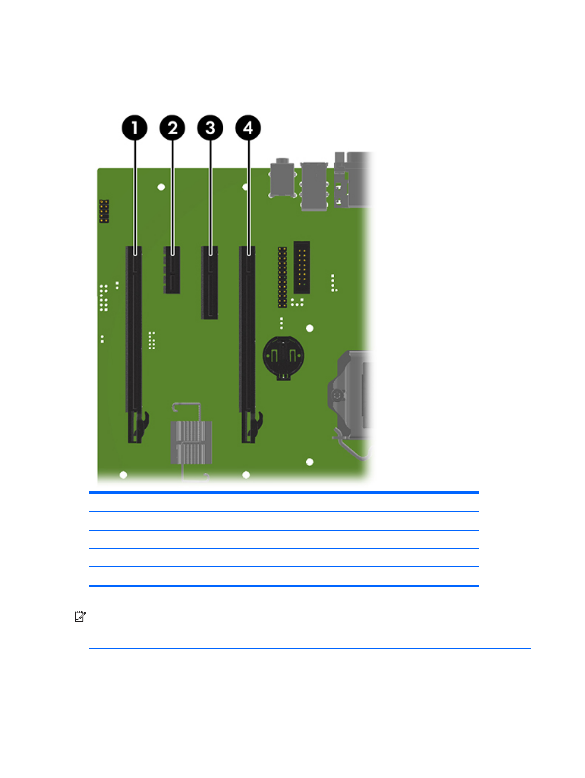
Slot identification and description
Maximum power used by all slots must not exceed total system power and is subject to configuration
limitations.
Slot Type Mechanical compatibility Electrical compatibility
1 PCIe2x16(4) x16 x4
2 PCIe2x1 x1 x1
3PCIe2x4(1) x4 x1
4PCIe3x16 x16 x16
NOTE: The PCIe designators indicate the mechanical connector size and number of electrical PCIe lanes
routed to an expansion slot. For example, x16(4) means that the expansion slot is mechanically a x16 length
connector, with 4 PCIe2 lanes supported.
44 Chapter 3 Component replacement information and guidelines
Page 55

Installation sequence recommendations
Load
order
NOTE: Slot sequenced from the board edge to the rear I/O aperture.
Card description Slot 1 Slot 2 Slot 3 Slot 4
1 PCIe graphic card Only
2 Second PCIe graphic card Only
3 PCIe audio card 1st 2nd
4 PCIe NIC card 1st 2nd
5 PCIe 1394 card 1st 2nd
6 Second serial port kit 1st 2nd
7 Parallel port kit 1st 2nd
8 eSATA bulkhead kit 1st 2nd 3rd
Hard drives and optical disc drives
Handling hard drives
CAUTION: Take proper precautions when handling hard drives to prevent loss of work and damage to the
computer or drive.
●
Do not remove hard drives from the shipping package for storage. Keep hard drives in their protective
packaging until they are mounted in the computer.
●
Always shut down the operating system, turn off the power, and unplug the power cord. Never remove
a drive while the computer is on or in standby mode.
●
Before handling a drive, make sure you discharge static electricity. While handling a drive, avoid
touching the connector.
●
Handle a drive carefully. Do not drop it from any height.
●
To prevent possible ESD damage when the drive is installed, connect the drive power cable before
connecting the data cable. This discharges accumulated static electricity through the drive power cable
to the computer chassis.
●
Do not use excessive force when inserting a drive.
●
Avoid exposing a hard drive to liquids, temperature extremes, or products that have magnetic fields
such as monitors or speakers.
●
If you must mail a drive, use a bubble-pack mailer or other protective packaging and label the package
“Fragile: Handle With Care.”
Removal and replacement tips
●
To verify the type, size, and capacity of the storage devices installed in the computer, run Computer
Setup (f10) Utility.
●
Adding a new drive may require that you make new connections from the drive to the system board.
Note that:
Component replacement guidelines 45
Page 56

◦
The primary Serial ATA (SATA) hard drive must be connected to the dark blue primary SATA
connector on the system board labeled SATA0.
◦
Connect a secondary hard drive to SATA.
◦
Connect SATA optical drives to the black SATA2 connector.
◦
Connect an optional eSATA adapter cable to the black ESATA connector on the system board.
◦
Connect a media card reader USB cable to the USB connector on the system board labeled MEDIA.
If the media card reader has a 1394 port, connect the 1394 cable to the 1394 PCI card.
Drive installation and cabling scenarios
This section presents cabling guidelines for the most common maximum storage configurations. If you add
or remove drives, HP recommends you follow these guidelines for highest drive performance and efficient
cable routing.
SATA cable connection guidelines
Configuration / PCA
SATA connector
HDD x1 ODD x1 1st HDD 1st ODD e-SATA
HDD x1 ODD x2 1st HDD 1st ODD 2nd ODD e-SATA
HDD x2 ODD x1 1st HDD 2nd HDD 1st ODD e-SATA
HDD x2 ODD x2 1st HDD2nd HDD1st ODD2nd ODD e-SATA
HDD x3 ODD x1 1st HDD 2nd HDD 3rd HDD 1st ODD e-SATA
HDD x3 ODD x2 1st HDD 2nd HDD 3rd HDD 1st ODD 2nd ODD
SATA 0 SATA 1 SATA 2 SATA 3 SATA 5
Memory
Supported DIMM configurations
NOTE: Mirroring and DIMM sparing are not supported.
●
Four DIMM slots
●
Unbuffered ECC/nECC DIMMS only
●
Maximum capacity: 32 GB
BIOS errors and warnings
The BIOS generates warnings/errors on invalid memory configurations:
●
If the BIOS can find a valid memory configuration by disabling plugged-in memory, it does so and
reports a warning during POST. the workstation can still be started. The warning will indicate the
location of the failed DIMM on the system board.
●
If there is no way for the BIOS to obtain a valid memory configuration by disabling plugged-in memory,
the BIOS halts with a diagnostics 2006 code for memory error (five beeps and blinks).
46 Chapter 3 Component replacement information and guidelines
Page 57
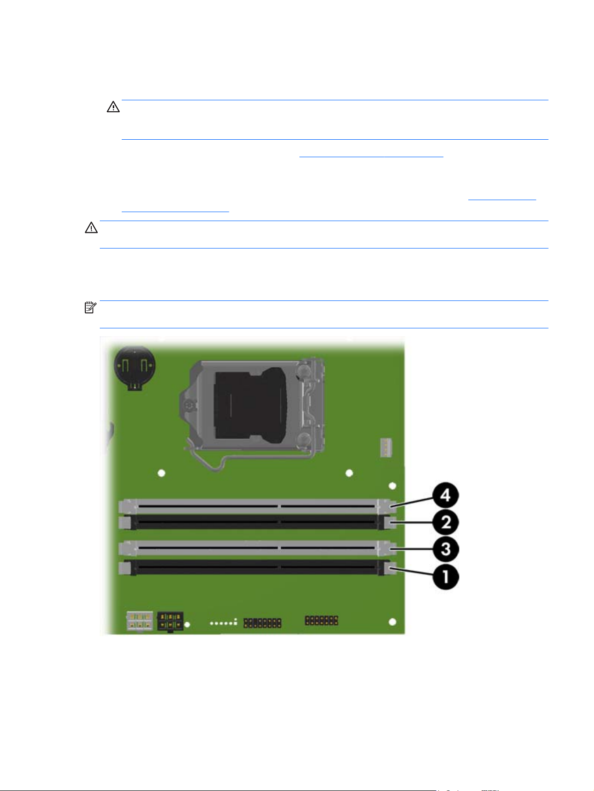
DIMM installation guidelines
●
Install only HP-approved DDR3 DIMMs
CAUTION: HP ships only DIMMs that are electrically and thermally compatible with this workstation.
Because third-party DIMMs might not be electrically or thermally compatible, they are not supported by
HP.
●
Install only HP-approved DDR3 DIMMs. See
compatible with the workstation.
●
Do not intermix DIMMs of different technologies. ECC Unbuffered DIMMs (UDIMMs), Registered DIMMs
(RDIMMs), and Load Reduced DIMMs (LRDIMMs) are supported on your workstations.
configurations on page 46 specifies which technologies are supported on each platform.
CAUTION: DIMMs and their sockets are keyed for proper installation. To prevent socket or DIMM damage,
align these guides properly when installing DIMMs.
DIMM installation order
Install DIMMs in this order.
NOTE: If you install DIMMs of different sizes, load them in order of size, starting with largest and finishing
with the smallest (largest in DIMM 1, smallest in last loaded DIMM).
http://www.hp.com/go/quickspecs to find DIMMs that are
Supported DIMM
Component replacement guidelines 47
Page 58

Power supply
Power supply specifications
All power supplies have these specifications:
●
Wide-ranging, active Power Factor Correction (PFC)
●
FEMP Standby Power compliant @115V (<1W in S5 – Power Off)
●
Surge tolerant (withstands power surges up to 2000V)
Power supply 90% efficient
Operating voltage range 90–264 VAC
Rated voltage range 100–240 VAC
Rated line frequency 50–60 Hz
Operating line frequency range 47–63 Hz
280 W
Rated input current
Heat dissipation, typical
630.2 btu/hr (158.8 kcal/hr)
(configuration and software dependent)
Heat dissipation, maximum
899.1 btu/hr (226.6 kcal/hr)
(configuration and software dependent)
Power supply fan
All fans are variable speed
Built-in Self Test LED No
Power consumption in sleep mode <4 W
3.6A @
100–240 VAC
One fan, 80mm x 25mm
48 Chapter 3 Component replacement information and guidelines
Page 59

Power consumption and heat dissipation
Power consumption and heat dissipation specifications are available for multiple configurations. To review
available specifications, go to
To reach zero power consumption, unplug the workstation from the power outlet or use a power strip with an
on/off switch. For additional information about power-saving features, see the operating system installation
instructions.
This product is in compliance with U.S. Executive Order 13221.
http://www.hp.com/go/quickspecs.
Resetting the power supply
If an overload triggers the power supply overload protection, power is immediately disconnected.
To reset the power supply:
1. Disconnect the power cord from the workstation.
2. Determine what caused the overload and fix the problem. For troubleshooting information, see
Diagnostics and troubleshooting on page 51.
3. Reconnect the power cord and restart the workstation.
When you turn off the workstation through the operating system, power consumption falls below what is
considered low power consumption but does not reach zero. This low power consumption feature extends
the life of the power supply.
System board
If you replace the system board:
●
Make a note of the cable connections before disconnecting them from the system board.
●
Follow good cable management practices. See
The following tables show system cabling for the workstations.
Cable management on page 40.
Component replacement guidelines 49
Page 60

System cabling
System cabling
System board components on page 4 to determine the location of system board connectors.
See
PSU cable PCA (Main Power) P1 (White)
PSU cable PCA (PWR COMM) P2 (White)
PSU cable PCA (CPU Power) P3 (White)
SATA power cable PCA P160 (Black)
SATA power cable First hard drive (Bay 3) P30 (Black)
SATA power cable Second hard drive (Bay 2) P20 (Black)
SATA power cable First optical drive (Bay 1) P12 (Black)
Speaker PCA P6 (White)
Cooler fan cable PCA P8 (White)
System fan cable PCA P11 (Brown)
Front audio cable PCA P23 (Blue)
Front LED/Power button cable PCA P5 (Black)
Cable To Cable designator on system board
Front USB 2.0 cable PCA P24(Yellow)
Front USB 3.0 cable PCA P26 (Blue)
Serial cable (optional)
Parallel cable (optional)
Hood sensor PCA P125 (White)
Chassis solenoid lock PCA P124 (Black)
SATA cable First HDD SATA0 (Blue)
SATA cable Second HDD SATA1 (Black)
SATA cable First ODD SATA2 (Black)
eSATA bracket cable (optional) First external SATA device SATA5 (Black)
PCA P52 (Black)
PCA P126 (Black)
50 Chapter 3 Component replacement information and guidelines
Page 61

4 Diagnostics and troubleshooting
This chapter describes the tools available for diagnosing and troubleshooting system issues.
Topics
Calling support on page 51
Locating ID labels on page 52
Locating warranty information on page 52
Diagnosis guidelines on page 52
Troubleshooting checklist on page 53
Using HP PC Hardware Diagnostics (UEFI) on page 64
Diagnostic codes and errors on page 64
Calling support
At times you might encounter an issue that requires support. When you call support:
●
Have the computer readily accessible.
●
Write down the computer serial numbers, product numbers, model names, and model numbers and
have them in front of you.
●
Note any applicable error messages.
●
Note any add-on options.
●
Note the operating system.
●
Note any third-party hardware or software.
●
Note the details of any blinking LEDs on the front of the computer (tower and desktop configurations)
or on the side of the computer (all-in-one configurations).
●
Note the applications you were using when you encountered the problem.
NOTE: When calling in for service or support, you might be asked for the product number (example:
PS988AV) of the computer. If the computer has a product number, it is generally located next to the 10-digit
serial number of the computer.
NOTE: On most models, the serial number and product number labels can be found on the top or side panel
and at the rear of the computer (tower and desktop configurations) or on a pull-out card on the side of the
display (all-in-one configurations).
For a listing of all worldwide support phone numbers, go to http://www.hp.com/support, select your region,
and click Connect with HP in the upper-right corner.
Calling support 51
Page 62
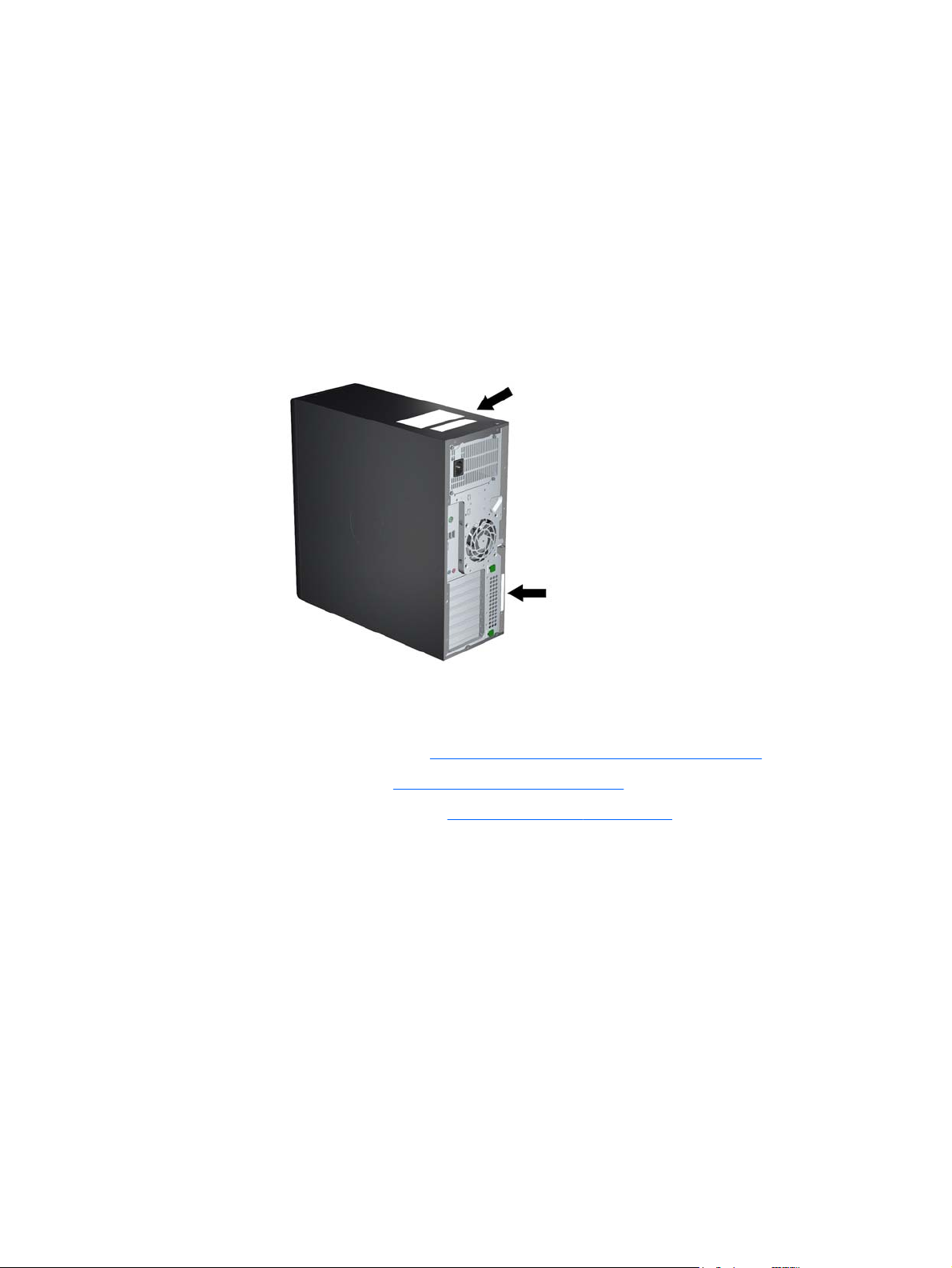
Locating ID labels
To assist in troubleshooting, product, serial, and authentication numbers are available on each computer.
●
All workstations have a serial number (unique for each workstation) and product number. Have these
numbers available when you contact support.
●
The Certificate of Authentication (COA) is used for systems with Windows 7 preinstalled.
●
The Genuine Microsoft Label (GML) is used for systems with Windows 8 preinstalled.
●
A service label shows the build ID and Feature Byte strings, which are needed for system board
replacement.
In general, these labels can be found on the top, rear, or bottom of the chassis (tower and desktop
configuration). Your computer might look different from the illustration.
Locating warranty information
To locate base warranty information, go to http://www.hp.com/support/warranty-lookuptool.
To locate an existing Care Pack, go to
To extend a standard product warranty, go to
upgraded service levels to extend and expand a standard product warranty.
http://www.hp.com/go/lookuptool.
Diagnosis guidelines
If you encounter a problem with the computer, monitor, or software, the following sections provide a list of
general suggestions that help you isolate and focus on the problem before taking further action.
Diagnosis at startup
●
Verify that the computer and monitor are plugged into a working electrical outlet.
●
Remove all CDs, or USB drive keys from your system before turning it on.
●
Verify that the computer is turned on and the blue power light is blue (normal operation) and not red
(error state).
http://www.hp.com/hps/carepack. HP Care Pack Services offer
52 Chapter 4 Diagnostics and troubleshooting
Page 63

●
If you have installed an operating system other than the factory-installed operating system, check to be
sure that it is supported on your system, go to
●
Verify that the monitor is turned on and the green monitor light is on. Note that not all monitors are
equipped with LED lights to indicate their functionality.
●
Turn up the brightness and contrast controls of the monitor if the monitor is dim.
Diagnosis during operation
●
Look for blinking LEDs on the side of the computer. The blinking lights are error codes that will help you
diagnose the problem. Refer to the
document for information on interpreting diagnostic lights and audible codes.
●
Check all cables for loose or incorrect connections.
●
Wake the computer by pressing any key on the keyboard or the power button. If the system remains in
suspend mode, shut down the system by pressing and holding the power button for at least four
seconds, then press the power button again to restart the system. If the system does not shut down,
unplug the power cord, wait a few seconds, then plug it in again. If it does not restart, press the power
button to start the computer.
●
Reconfigure the computer after installing a non–plug and play expansion board or other option.
●
Be sure that all required device drivers have been installed. For example, if you have connected a
printer, you must install a printer driver.
●
If you are working on a network, plug another computer with a different cable into the network
connection. There might be a problem with the network plug or cable.
http://www.hp.com/go/quickspecs.
Diagnostic LED and audible (beep) codes on page 64 section of this
●
If you recently added new hardware, remove the hardware and verify if the computer functions
properly.
●
If you recently installed new software, uninstall the software and verify if the computer functions
properly.
●
If the screen is blank, plug the monitor into a different video port on the computer if one is available.
Alternatively, replace the monitor with a monitor that you know is working properly.
●
Upgrade the BIOS. A new release of the BIOS might have been released that supports new features or
fixes your problem.
●
Press the caps lock key. If the caps lock LED toggles on or off, the keyboard is operating correctly.
Troubleshooting checklist
Before running diagnostic utilities, make sure that the following conditions are met:
●
The computer is connected to a working electrical outlet and powered on, and the power light is
illuminated.
●
The monitor (for tower or desktop configurations) is connected to a working electrical outlet and
powered on, and the power light is illuminated.
●
The monitor brightness and contrast are properly adjusted.
●
The keyboard is operating correctly (press and hold any key and listen for a beep).
●
All cables are properly connected.
●
All necessary device drivers are installed.
Troubleshooting checklist 53
Page 64

●
All external media (such as optical disks or USB drive keys) are removed before startup.
●
The latest version of BIOS, drivers, and software are installed.
HP troubleshooting resources and tools
This section provides information to guide you in troubleshooting your system.
Online support
Online support resources include web-based troubleshooting tools, technical knowledge databases, driver
and patch downloads, online communities, and product change notification services.
The following websites are also available to you:
●
http://www.hp.com—Provides useful product information.
●
http://www.hp.com/support/workstation_manuals—Provides the latest online documentation.
●
http://www.hp.com/go/workstationsupport—Provides technical support information for workstations.
●
http://www8.hp.com/us/en/contact-hp/phone-assist.html—Provides a listing of the worldwide
technical support telephone numbers. Select your region.
●
http://www.hp.com/support/workstation_swdrivers—Provides access to software and drivers for
workstations.
HP Support Center
To help you troubleshoot problems yourself, HP provides the HP Support Center. The HP Support Center is a
portal to an extensive selection of online tools. To access the HP Support Center, complete the following
steps:
1. Go to
2. Select Troubleshooting and your product.
http://www.hp.com/support and select your country.
HP Chat Support
HP Chat Support is a set of web-based support tools that automate and speed up the resolution of problems
concerning desktop computing, tape storage, and printing.
HP Chat Support enables you to electronically submit a support ticket to HP over the web. When you submit a
support ticket, HP Chat Support collects information about the workstation and passes it to an online support
specialist. The collection of information might take up to 30 seconds, depending on the workstation
configuration. When you submit a support ticket, you receive a confirmation message containing your case
ID, the support hours for your location, and the estimated time of response.
For more information about HP Chat Support, go to
NOTE: This feature is not available for Linux.
http://instantsupport.hp.com/.
Customer Advisories, Customer and Security Bulletins, and Customer Notices
To find advisories, bulletins, and notices:
1. Go to
2. Select Drivers and Downloads and your product.
3. In the left navigation pane under Knowledge Base options, select Advisories, Bulletins & Notices.
54 Chapter 4 Diagnostics and troubleshooting
http://www.hp.com/go/workstationsupport and select your country.
Page 65

Product Change Notifications
Product Change Notifications (PCNs) are proactive notifications for product changes occurring within a 30- to
60-day window of the effective date of the change in the manufacturing process. PCNs give customers
advance notice of changes to their product, such as an updated BIOS version that they might need to decide
whether to download prior to the change taking place. To view a list of PCNs, go to the Advisories, Bulletins
& Notices page for your product.
Helpful hints
If you encounter a problem with the workstation, monitor, or software, the following general suggestions
might help you isolate and focus on the problem before taking further action.
At startup
●
Verify that the workstation is plugged into a functional AC outlet.
●
Remove all optical discs and USB flash drives before starting the workstation.
●
Verify that the workstation is on and the power light is on.
●
If you have installed an operating system other than the factory-installed operating system, confirm
that it is supported on your system by going to
●
Verify that the internal display panel is lit.
●
If the internal display panel is dim, turn up the brightness.
http://www.hp.com/go/quickspecs.
●
If you have an external monitor:
◦
◦
◦
During operation
●
Beeps and blinking lights on the workstation are error codes that can help you diagnose problems. For
more information on interpreting these codes, see
on page 64.
●
Press and hold any key. If the system beeps, your keyboard is operating correctly.
●
Check all cables for loose or incorrect connections.
●
Wake the workstation by pressing the power button or any key on the keyboard. If the system remains
in suspend mode, shut down the system by pressing and holding the power button for at least four
seconds. Then press the power button again to restart the system.
If the system does not shut down, unplug the power cord, wait a few seconds, and then plug it in again.
If the system does not restart, press the power button.
●
After installing a non-PnP expansion board or other option (such as a diskette drive), restart the
workstation.
●
Be sure that all required device drivers have been installed. For example, if you have connected a
printer, you must install a printer driver.
Verify that the monitor is plugged into a functional AC outlet.
Verify that the monitor is on and the green monitor light is on.
If the monitor is dim, turn up the brightness and contrast controls.
Diagnostic LED and audible (beep) codes
●
If you are working on a network, use another cable to plug your workstation into the network
connection. If you still cannot connect, there might be a problem with the network plug.
HP troubleshooting resources and tools 55
Page 66

●
If you recently added new hardware, remove the hardware to see whether the workstation functions
properly.
●
If you recently installed new software, uninstall the software to see whether the workstation functions
properly.
●
If the internal display panel on an all-in-one workstation is blank, open the workstation and be sure that
both ends of the cable between the system board and the internal display panel are connected. If you
are using a graphics card, verify that the card is properly installed.
●
Upgrade the BIOS. A new release of the BIOS might have been released that supports new features or
fixes your problem.
●
For more detailed information, see
Customer Self Repair
Under the Customer Self Repair programs, you can order a replacement part and install the part without onsite HP technical assistance. Customer Self Repair might be required for some components. For more
information, go to
NOTE: Some components are not eligible for Customer Self Repair and must be returned to HP for service.
Call support for further instructions before attempting to remove or repair these components.
Diagnostics and troubleshooting on page 51.
http://www.hp.com/go/selfrepair and select your product.
56 Chapter 4 Diagnostics and troubleshooting
Page 67

Troubleshooting scenarios and solutions
This section presents troubleshooting scenarios and possible solutions for a Windows-based system.
Solving minor problems
Problem Cause Possible Solution
Workstation appears frozen and
does not shut down when the
power button is pressed.
Workstation seems to be frozen. Program in use has stopped
Workstation date and time
display is incorrect.
Workstation appears to pause
periodically.
Cursor does not move using the
arrow keys on the keypad.
Poor performance is
experienced.
Software control of the power
switch is not functional.
responding to commands.
Real-time clock (RTC) battery
might need replacement.
Network driver is loaded and no
network connection is established.
num lock is on. Press num lock. The num lock key can be disabled or enabled in
Processor is hot. 1. Verify that airflow to the computer is not blocked.
Hard drive is full. Transfer data from the hard drive to create more space on the
1. Press and hold the power button for at least four seconds
until the computer shuts down.
2. Disconnect the electrical plug from the outlet.
3. Restart the computer.
1. If possible, use the Windows Task Manager to isolate and
terminate the offending process.
2. Attempt the normal Windows shutdown procedure.
3. Restart the computer using the power button.
1. Reset the date and time in the Control Panel.
2. Replace the RTC battery.
Establish a network connection, or use Computer Setup (f10)
Utility or Microsoft Windows Device Manager to disable the
network controller.
Computer Setup (f10) Utility.
2. Verify that chassis fans are connected and working
properly. Some fans operate only when needed.
3. Verify that the processor heatsink is installed properly.
hard drive.
Workstation powered off
automatically and the Power
LED flashes red 2 times (once
every second), followed by a 2second pause, and then two
simultaneous beeps sounded.
System does not turn on, and
the LEDs on the front of the
computer are not flashing.
Processor thermal protection is
activated.
A fan might be blocked or not
turning.
OR
The processor heatsink is not
properly attached to the processor.
System cannot power on. Press and hold the power button for less than four seconds. If
1. Verify that the computer air vents are not blocked.
2. Open the access panel and press the computer power
button.
3. Verify that the system fan is running.
4. Verify that the processor heatsink fan spins. If the fan is
not spinning, verify that the heatsink fan cable is plugged
into the system board connector and that the heatsink is
properly seated.
5. Replace the processor heatsink.
the hard drive LED turns green:
1. To find a faulty device, remove all devices one at a time:
a. Disconnect AC power to the computer.
b. Remove a device.
c. Reconnect AC power and turn on the computer.
Troubleshooting scenarios and solutions 57
Page 68

Problem Cause Possible Solution
2. Repeat this process until the faulty device is identified.
Remove the graphics card last. Replace the faulty device.
3. If no faulty device is found, replace the system board.
OR
1. Press and hold the power button for less than four
seconds. If the hard drive LED does not illuminate:
a. Verify that the computer is plugged into a working
AC outlet.
b. Verify that the power button harness is connected
to the inline front panel I/O device assembly
connector.
2. Verify that the power supply unit (PSU) cables are
connected to the system board.
3. Verify power supply unit PSU functionality (Tower only):
a. Disconnect the AC power.
b. Unplug cables connected to the system board.
c. Reconnect AC power
●
●
If the PSU fan spins, the PSU is good; replace
the system board.
If the PSU fan does not spin or the LED does
not illuminate, replace the PSU.
Solving hard drive problems
Problem Cause Solution
Hard drive error Hard drive has bad sectors or
Disk transaction problem The directory structure is bad, or
Drive not found (identified) Improper cable connection On computers with discrete data and power cables, make sure
Locate and block the usage of bad sectors. If necessary,
has failed.
there is a problem with a file.
Improperly seated hard drive On systems with blind-mate drive connections, check for
reformat the hard drive.
If the drive is detected by the UEFI, run F2 Diagnostics Drive
Test.
1. Open Windows Explorer and select a drive.
2. Right click on the drive and select Properties > Tools.
3. Under Error-checking, select Check Now.
that the data and power cables are securely connected to the
hard drive. (See the Hard drive section of this guide for
connection details.)
connector damage on the drive and in the chassis.
Reseat the hard drive and its carrier in the chassis to make
sure that a proper connection. (See the Hard drive section of
this guide for connection details.)
58 Chapter 4 Diagnostics and troubleshooting
Page 69

Problem Cause Solution
Non-system disk or NTLDR missing
message
The system might not have
automatically recognized a
newly installed device.
Drive responds slowly
immediately after power-up.
System is trying to start from
nonbootable media.
System is trying to start from a
damaged hard drive.
System files missing or not
properly installed.
1. Run Computer Setup (f10) Utility.
2. If the system does not recognize the new device, verify
that the device is listed in Computer Setup (f10) Utility.
If it is listed, the probable cause is a driver problem. If it
is not listed, the probable cause is a hardware problem.
3. If this drive is newly installed, enter Setup and try
adding a POST delay under Advanced > Power-On.
Run Computer Setup (f10) Utility and increase the POST Delay
in Advanced.> Power-On Options
Remove the optical disc or USB drive.
1. Insert a bootable system optical disc or USB drive and
restart the computer.
2. If the hard drive is still inaccessible and MBR Security is
enabled, try restoring the previously saved MBR image
by entering Setup and selecting Security > Restore
Master Boot Record.
1. Insert a bootable system optical disc or USB drive and
restart.
2. Verify that the hard drive is partitioned and formatted.
3. Install the system files for the appropriate operating
system, if necessary.
Workstation will not start. Hard drive is damaged. Replace the hard drive.
Solving display problems
These suggestions apply to monitors connected to desktop and tower configurations, and to external
monitors connected to all-in-one configurations.
Problem Cause Solution
Blank screen (no video). The cable connections are not
Hard drive boot disabled in
Computer Setup.
correct.
The monitor is off. Turn the monitor on (LED is on). You might need to refer to
Screen blanking utility installed
or energy saver features
enabled.
System ROM is bad; system is
running in FailSafe Boot Block
mode (indicated by 8 beeps).
Fixed-sync monitor does not
sync at the resolution specified.
Run Computer Setup (f10) Utility and enable the hard drive
entry in the Storage > Boot Order list.
Verify the cable connections from the monitor to the
computer and to a working electrical outlet.
the monitor manual for an explanation of LED signals.
Press a key or the mouse button and, if set, enter your
password.
Reflash the ROM using a SoftPaq.
Verify that the monitor can accept the same horizontal scan
rate as the resolution specified.
Computer is in Hibernate mode. Press the power button to resume from Hibernate mode.
Troubleshooting scenarios and solutions 59
Page 70

Problem Cause Solution
The display works properly during
the POST but goes blank when the
operating system starts.
Power LED flashes red 6 times (once
every second), followed by a twosecond pause, and then the
computer beeps 6 times.
Workstation monitor settings
are not compatible with the
monitor.
The display settings in the
operating system are
incompatible with your graphics
card and monitor.
Pre-video graphics error. For systems with a graphics card:
1. When you see Press f8 in the bottom-right corner of the
screen, restart the computer and press f8 during
startup.
2. Using the keyboard arrow keys, select Enable VGA
Mode, and then press enter.
3. For Windows, double-click the Display icon in the
Control Panel and then select the Settings tab.
4. Use the sliding control to reset the resolution.
1. For Windows, restart your computer in VGA mode.
2. After the operating system starts, change the display
settings to match those supported by your graphics card
and monitor.
3. Refer to your operating system and graphics card
documentation for information about changing display
settings.
1. Reseat the graphics card.
2. If the card requires external power, make sure the
power cable is properly connected.
3. Replace the graphics card.
4. Replace the system board.
For systems with no graphics card installed, the CPU may
have no integrated graphics capability.
Monitor does not function when used
with Energy Saver features.
Dim characters The brightness and contrast
Blurry video or requested resolution
cannot be set.
The picture is broken up, rolls,
jitters, or flashes.
Vibrating or rattling noise coming
from inside a CRT monitor when
powered on.
Monitor without Energy Saver
capabilities is being used with
Energy Saver features enabled.
controls are not set properly.
Cables are not properly
connected.
If the graphics controller was
upgraded, the correct video
drivers might not be loaded.
Monitor cannot display
requested resolution.
The monitor connections might
be faulty, or the monitor might
be incorrectly adjusted.
Monitor must be degaussed. Degauss the monitor.
Monitor degaussing coil has
been activated.
Disable the monitor Energy Saver feature.
Adjust the monitor brightness and contrast controls.
Verify that the graphics cable is connected to the graphics
card and the monitor.
Install the video drivers included in the upgrade kit, or
download and install the latest drivers for your graphics card
from
http://welcome.hp.com/country/us/en/support.html.
Change the requested resolution.
1. Be sure the monitor cable is securely connected to the
computer.
2. In a multiple CRT monitor system, make sure that the
monitors' electromagnetic fields are not interfering with
each other. Move them apart if necessary.
3. Move fluorescent lights or fans that are too close to the
CRT monitor.
None. It is normal for the degaussing coil to be activated
when the monitor is turned on.
60 Chapter 4 Diagnostics and troubleshooting
Page 71

Problem Cause Solution
Clicking noise coming from inside a
CRT monitor.
High pitched noise coming from
inside a flat-panel monitor.
Fuzzy focus; streaking, ghosting, or
shadowing effects; horizontal
scrolling lines; faint vertical bars; or
unable to center the picture on the
screen (flat-panel monitors using an
analog VGA input connection only.)
Some typed symbols do not appear
correctly.
Solving audio problems
Electronic relays have been
activated inside the monitor.
Brightness and contrast settings
are too high.
Flat-panel monitor’s internal
digital conversion circuits might
be unable to correctly interpret
the output synchronization of
the graphics card.
The font you are using does not
support that symbol.
None. It is normal for some monitors to make a clicking noise
when turned on and off, when going in and out of Standby
mode, and when changing resolutions.
Lower brightness and contrast settings.
1. Select the monitor’s Auto-Adjustment option in the
monitor’s onscreen display menu.
2. Manually synchronize the Clock and Clock Phase
onscreen display functions.
3. Download SoftPaq SP22333 to assist with the
synchronization).
Use the Character Map to locate and select the appropriate
symbol.
For Windows 7, select Start > All Programs > Accessories >
System Tools > Character Map. You can copy the symbol
from the Character Map into a document.
For Windows 8, from the Start screen, type character
map. The application appears under the Apps heading.
Problem Cause Solution
Sound does not come out of the
speaker or headphones.
Software volume control is
turned down.
The external speakers are not
turned on.
External speakers plugged into
the wrong audio jack.
Digital CD audio is not enabled. Enable digital CD audio:
Headphones or devices
connected to the line-out
connector have muted the
internal speaker.
Volume is muted. 1. From the Control Panel, select Sound, Speech and Audio
Double-click the Speaker icon on the taskbar, and then use
the volume slider to adjust the volume.
Turn on the external speakers.
See your sound card documentation for proper speaker
connection.
1. From the Control Panel, select System.
2. On the Hardware tab, select the Device Manager button.
3. Right-click the CD/DVD device and select Properties.
4. On the Properties tab, select Enable digital CD audio for
this CD-ROM device.
Turn on and use headphones or external speakers, if
connected, or disconnect headphones or external speakers.
Devices, and then select Sounds and Audio Devices.
2. Deselect the Mute checkbox.
Noise or no sound comes out of the
speakers or headphones.
Computer is in Standby mode. Press the power button to resume from Standby mode.
1. If you are using digital speakers that have a stereo jack
and you want the system to autoswitch to digital, use a
Troubleshooting scenarios and solutions 61
Page 72

Problem Cause Solution
stereo-to-mono adapter to engage the auto sense
feature, or use multimedia device properties to switch
the audio signal from analog to digital.
2. If the headphones have a mono jack, use the multimedia
device properties to switch the system to analog out.
NOTE: If you set digital as the Output Mode, the
internal speaker and external analog speakers no longer
output audio until you switch back to an auto sense or
analog mode.
If you set analog as the Output Mode, external digital
speakers do not function until you change the output
mode back to an auto-sense or digital mode.
Sound occurs intermittently. Processor resources are being
Workstation appears to be locked up
while recording audio.
Solving printer problems
Problem Cause Solution
Printer does not print. Printer is not turned on and
Shut down all open processor-intensive applications.
used by other open applications.
The hard drive might be full. 1. Before recording, be sure there is enough free space on
the hard drive.
2. Try recording the audio file in a compressed format.
Turn the printer on and be sure it is online.
online.
The correct printer driver for the
application is not installed.
If you are on a network, you
might not have made a
connection to the printer.
1. Install the correct printer driver for the application.
2. Try printing using the MS-DOS command:
DIR C:\> [printer port]
Replace printer port with the address of the printer
used. If the printer works, reload the printer driver.
Make the proper network connection to the printer.
Printer might have failed. Run printer self-test.
Printer does not turn on. The cables might not be
connected properly.
62 Chapter 4 Diagnostics and troubleshooting
Page 73

Solving power supply problems
This section presents power supply troubleshooting scenarios.
Testing power supply
Problem Cause Solution
PSU shuts down intermittently. Power supply fault. Replace the PSU.
Workstation powers off and the
Power LED flashes red 2 times (once
every second), followed by a twosecond pause.
Power LED flashes red (once every 2
seconds).
Processor thermal protection is
activated.
A fan might be blocked or not
turning.
OR
The processor heatsink fan
assembly is not properly
attached to the processor.
Power failure (power supply is
overloaded).
1. Make sure that the workstation air vents are not
blocked.
2. Open the access panel and press the workstation power
button.
3. Verify that the system fan is running.
4. Verify that the processor heatsink fan spins.
If the heatsink fan is not spinning, verify that the fan
cable is plugged into the system board connector. Verify
that the fan is properly seated.
5. Replace the processor heatsink.
1. Determine whether a device is causing the problem by
performing the following:
a. Disconnect AC power.
b. Remove all attached devices.
c. Turn on the workstation.
If the system enters the POST, perform the following:
a. Power off the workstation.
b. Replace one device at a time and repeat this
procedure until a failure occurs.
c. Replace the device causing the failure.
d. Continue adding devices one at a time to verify
that all devices are functioning.
2. Verify power supply functionality (Tower only).
a. Disconnect AC power.
b. Unplug all system board power cables.
c. Plug in AC power.
●
If the PSU fan spins and the LED is
illuminated (see
on page 63), the power supply is good.
Replace the system board.
●
If the PSU fan does not spin or the LED does
not illuminate (see
on page 63), replace the power supply.
Testing power supply
Testing power supply
Troubleshooting scenarios and solutions 63
Page 74

Using HP PC Hardware Diagnostics (UEFI)
HP PC Hardware Diagnostics is a Unified Extensible Firmware Interface (UEFI) that allows you to run
diagnostic tests to determine whether the computer hardware is functioning properly. The tool runs outside
the operating system so that it can isolate hardware failures from issues that may be caused by the
operating system or other software components.
To start HP PC Hardware Diagnostics UEFI:
1. Turn on or restart the computer, quickly press esc, and then press F2.
The BIOS searches three places for the HP PC Hardware Diagnostics (UEFI) tools in the following order:
a. Connected USB drive
NOTE: To download the HP PC Hardware Diagnostics (UEFI) tool to a USB drive, see
HP PC Hardware Diagnostics (UEFI) to a USB device on page 64.
b. Hard drive
c. BIOS
2. Click the type of diagnostic test you want to run, and then follow the on-screen instructions.
NOTE: If you need to stop a diagnostic test, press Esc.
Downloading HP PC Hardware Diagnostics (UEFI) to a USB device
NOTE: The HP PC Hardware Diagnostics (UEFI) download instructions are provided in English only.
1. Go to http://www.hp.com.
2. Point to Support located at the top of the page, and then click Download Drivers.
3. In the text box enter the product name, and then click Go.
-or-
Click Find Now to let HP automatically detect your product.
4. Select your computer model, and then select your operating system.
5. In the Diagnostic section, click HP UEFI Support Environment.
Downloading
– or –
Click Download, and then select Run.
Diagnostic codes and errors
This section presents information about diagnostic LED codes, LED color definitions, and POST error
messages to help you troubleshoot problems.
Diagnostic LED and audible (beep) codes
This section describes the front panel LED error and operation codes as well as the audible codes that might
occur before or during the POST.
64 Chapter 4 Diagnostics and troubleshooting
Page 75

Activity Possible cause Recommended action
Blue Power LED
*
on. No
Computer on.
beeps.
Blue Power LED
every two seconds.
*
blinks
*
No
beeps.
*
Blue Power LED
is off.* No
beeps.
*
*
No beeps.
blinks
*
blinks four
Blue Power LED
three times*, once per
second.
Blue Power LED
times*, once per second.
beeps.
Computer in Sleep mode
(S3-Suspend to RAM).
Select models only.
Computer in Hibernate
mode (S4-Suspend to
disk) or system is off (S5).
Computer in Sleep mode
(S3-Suspend to RAM).
Select models only.
Computer in Hibernate
*
mode (S4-Suspend to
No
disk).
N/A
User-selectable for details.
For the following LED activity and beeps, the beeps are heard through the chassis speaker. Blinks and beeps repeat for five cycles,
after which, only the blinks continue to repeat.
Red Power LED blinks two
times, once every second,
followed by a two-second
pause. Two beeps.
Red Power LED blinks three
times, once every second,
followed by a two-second
pause. Three beeps.
Red Power LED blinks four
times, once every second,
followed by a two-second
pause. Four beeps.
CPU thermal protection
activated by either of the
following methods:
●
A fan might be
blocked or not
turning.
●
The heatsink and fan
assembly is not
properly attached to
the CPU.
CPU not installed (not an
indicator of bad CPU).
Power failure (power
supply is overloaded).
CAUTION: Internal components might be powered even when the
computer is off. To prevent damage, disconnect the computer power
cord before you remove a component.
1. Make sure that the computer air vents are not blocked and the
cooling fan is running.
2. Open the access panel, press power button, and verify that the
CPU fan is spinning. If the CPU fan is not spinning, make sure the
fan cable is plugged into the computer board header. Make sure
the fan is fully and properly seated or installed.
3. If fan is plugged in and seated properly, but is not spinning, the
problem might be in the CPU fan. Contact HP for assistance.
4. Verify that the fan assembly is properly attached. If problems
persist, there might be a problem with the CPU heatsink. Contact
HP for assistance.
1. Verify that the CPU is present.
2. Reseat the CPU.
CAUTION: Internal components might be powered even when the
computer is off. To prevent damage, disconnect the computer power
cord before you remove a component.
1. Open the access panel and make sure that all power
connections are secure on the system board.
2. Check if a device is causing the problem by removing all
attached devices (such as hard, diskette, or optical disk drives,
and expansion cards.) Turn on the computer. If the system
enters the POST, power off and replace one device at a time;
repeat this procedure until failure occurs. Replace the device
that is causing the failure. Continue adding devices one at a time
to make sure that all devices are functioning properly.
Red Power LED blinks five
times, once every second,
Pre-video memory error. CAUTION: Internal components might be powered even when the
computer is off. To prevent damage, disconnect the computer power
cord before you remove a component.
Diagnostic codes and errors 65
Page 76

Activity Possible cause Recommended action
followed by a two-second
pause. Five beeps.
Red Power LED blinks six
times, once every second,
followed by a two-second
pause. Six beeps.
Red Power LED blinks seven
times, once every second,
followed by a two-second
pause. Seven beeps.
Red Power LED blinks eight
times, once every second,
followed by a two-second
pause. Eight beeps.
1. Reseat DIMMs.
2. Replace DIMMs one at a time to isolate faulty module.
3. Replace third-party memory with HP memory.
4. The problem might be on the system board. Contact HP for
assistance.
Pre-video graphics error. CAUTION: Internal components might be powered even when the
computer is off. To prevent damage, disconnect the computer power
cord before you remove a component.
1. Reseat the graphics card.
2. Verify the graphics auxiliary power cable is connected (if
applicable).
3. Confirm the graphics card is in the appropriate slot (PCIe x16).
4. The problem might be on the graphics card. Contact HP for
assistance.
System board failure
(ROM detected failure
prior to video).
Invalid ROM based on bad
checksum.
1. Clear CMOS.
NOTE: Refer to the Maintenance and Service Guide for the
computer model for detailed information on clearing CMOS.
2. The problem might be on the system board. Contact HP for
assistance.
CAUTION: Internal components might be powered even when the
computer is off. To prevent damage, disconnect the computer power
cord before you remove a component.
1. Clear CMOS.
NOTE: Refer to the Maintenance and Service Guide for the
computer model for detailed information on clearing CMOS.
2. Upgrade the ROM using SoftPaq, either from the hard drive, CD,
diskette, or USB removable device (for example, HP Drive Key).
See
ROM Flash on page 26. SoftPaq is a self-extracting
executable, which contains instructions for its use, that enables
you to upgrade the ROM. To download the Softpaq executable,
http://www.hp.com/go/workstationsupport.
go to
3. The problem might be on the system board. Contact HP for
assistance.
Red Power LED blinks nine
times, once every second,
followed by a two-second
pause. Nine beeps.
System does not power-on
and LEDs are not blinking.
No beeps.
System powers on but
does not start.
System unable to turn on. CAUTION: Internal components might be powered even when the
66 Chapter 4 Diagnostics and troubleshooting
1. The problem might be on the system board. Contact HP for
assistance.
2. The problem might be in the CPU. Contact HP for assistance.
computer is off. To prevent damage, disconnect the computer power
cord before you remove a component.
To resolve the problem, choose one of the following options:
Press and hold the power button for less than four seconds. If the
hard drive LED turns green, then:
1. Remove the expansion cards one at a time and try holding the
power button again for less than four seconds.
2. The problem might be on the system board. Contact HP for
assistance.
Page 77

Activity Possible cause Recommended action
Press and hold the power button for less than four seconds. If the
hard drive LED does not turn on green then:
1. Check that unit is plugged into a working AC outlet.
2. Open the access panel and check that the power button harness
is properly connected to the system board.
3. Check that all power supply cables are properly connected to
the system board.
4. Check the power supply functionality.
a. Disconnect the AC power.
b. Unplug cables connected to system board.
c. Plug in AC power.
●
If the power supply fan spins, the power supply is
good; replace the system board.
●
If the power supply fan does not spin or the LED does
not illuminate, replace the power supply.
*
The BIOS option you select controls the blue LED function during these suspend modes.
Diagnostic codes and errors 67
Page 78

LED color definitions
The following table describes what each LED light on the computer front panel signifies.
LED state LED color System status
Solid Blue System is on.
Flashing Blue System is in Standby.
Solid or flashing Red System has experienced an error. (See
None No light System is in Hibernate, or is off.
POST error messages
The Power-On Self Text (POST) is a series of diagnostic tests that runs automatically when the computer is
turned on.
Audible and visual messages occur before the operating system starts if the POST encounters a problem.
POST checks the following items to make sure that the computer system is functioning properly:
●
Keyboard
●
DIMMs
●
Diskette drives
●
All mass storage devices
●
CPUs
●
Controllers
●
Fans
●
Temperature sensors
POST error messages
on page 68.)
●
Cables (front/rear panels, audio, and USB ports)
The table shown next describes the POST error messages.
Screen message Probable cause Recommended action
102—System Board Failure Potential system board problem; contact HP Support.
110—Out of memory space for
option ROMs
161—Real-Time Clock Power
Loss
162—Systems Options Error 1. Run Computer Setup (f10) Utility and set default
Option ROM for a device could not run
because of memory constraints.
1. Run Computer Setup (f10) Utility and set default
68 Chapter 4 Diagnostics and troubleshooting
Run Computer Setup (f10) Utility to disable unneeded
option ROMs, and to enable ACPI/USB Buffers at Top of
Memory.
settings.
2. Replace the CMOS battery.
3. Replace the system board.
settings.
2. Replace the CMOS battery.
3. Replace the system board.
Page 79

Screen message Probable cause Recommended action
163—Time and Date Not Set
164—Memory Size Error Memory configuration is incorrect. Confirm that the correct memory is installed in the
201—Memory Error RAM failure. 1. Run Computer Setup (f10) Utility or the Windows
214—DIMM Configuration
Warning
●
Invalid time or date in
configuration memory.
●
RTC battery might need
replacement.
●
CMOS jumper might not be
properly installed.
DIMMs are not installed correctly (not
paired correctly).
1. Set the date and time from the Control Panel or in
Computer Setup (f10) Utility (depending on the
operating system).
2. If the problem persists, replace the RTC battery.
system.
utilities.
2. Be sure that memory modules are installed
correctly.
3. Verify the memory module type.
4. Remove and replace memory modules one at a time
to isolate faulty modules.
5. Replace faulty memory modules.
6. If the error persists after replacing memory
modules, replace the system board.
See the service label on the computer access panel for the
correct memory configurations, and reseat the DIMMs
accordingly.
301—Keyboard Error Keyboard failure. 1. Reconnect the keyboard with the computer
powered off.
2. Connect a keyboard directly to the computer
(instead of through a switch box).
3. Be sure that none of the keys are pressed.
4. Replace the keyboard.
303—Keyboard Controller Error I/O board keyboard controller is
defective or is not set properly.
304—Keyboard or System Unit
Error
510—Splash Screen image
corrupted
Keyboard failure. 1. Reconnect the keyboard with the computer powered
Splash Screen image has errors. Update system BIOS/UEFI.
1. Reconnect the keyboard with the computer powered
off.
2. Connect a keyboard directly to the computer
(instead of through a switch box).
3. Replace the system board.
off.
2. Connect a keyboard directly to the computer
(instead of through a switch box).
3. Be sure that none of the keys are pressed.
4. Replace keyboard.
5. Replace system board.
511—CPU Fan not detected Fan is not connected or is defective. 1. Reseat the fan cable.
2. Reseat the fan.
Diagnostic codes and errors 69
Page 80

Screen message Probable cause Recommended action
3. Replace the fan.
512—Rear chassis fan not
detected
513—Front Chassis fan not
detected
514—Power supply wattage
insufficient for hardware
configuration
515—Power supply fan not
detected
517—Memory fan not detected Memory fan missing, disconnected, or
518—PCI fan not detected PCI fan missing, disconnected, or
519—Hard drive fan not
detected
Fan missing, disconnected, or defective. 1. Reseat the fan cable.
Front fan missing, disconnected, or
defective.
Computer configuration requires more
power than the power supply can
provide
Power supply fan is disconnected or
defective.
defective.
defective.
Hard drive fan missing, disconnected, or
defective.
2. Reseat the fan.
3. Replace the fan.
1. Reseat the fan cable.
2. Reseat the fan.
3. Replace the fan.
Reduce the computer power consumption.
1. Reseat the power supply cables.
2. Replace the power supply.
1. Reseat the fan cable.
2. Reseat the fan.
3. Replace the fan.
1. Reseat the fan cable.
2. Reseat the fan.
3. Replace the fan.
1. Reseat the fan cable.
2. Reseat the fan.
520—Memory fan (2) not
detected
521—Memory fan (3) not
detected
522—Memory fan (4) not
detected
523—CPU fan (2) not detected CPU fan(2) missing, disconnected, or
524—Rear chassis fan(2) not
detected
Memory fan (2) missing, disconnected,
or defective.
Memory fan(3) missing, disconnected, or
defective.
Memory fan(4) missing, disconnected, or
defective.
defective.
Rear chassis fan(2) missing,
disconnected, or defective.
3. Replace the fan.
1. Reseat the fan cable.
2. Reseat the fan.
3. Replace the fan.
1. Reseat the fan cable.
2. Reseat the fan.
3. Replace the fan.
1. Reseat the fan cable.
2. Reseat the fan.
3. Replace the fan.
1. Reseat the fan cable.
2. Reseat the fan.
3. Replace the fan.
1. Reseat the fan cable.
2. Reseat the fan.
3. Replace the fan.
70 Chapter 4 Diagnostics and troubleshooting
Page 81

Screen message Probable cause Recommended action
525—Front chassis fan(2) not
detected
526—CPU Liquid Cooling pump
not detected
527—CPU Liquid Cooling pump
(2) not detected
528—CPU requires Liquid
Cooling solution
529—Unsupported WiFi
Device(s) Detected
917—Front Audio Not
Connected
918—Front USB Not Connected Front USB mechanism is missing or is not
Front chassis fan(2) missing,
disconnected, or defective.
Liquid cooling pump on CPU1 is not
detected.
Liquid cooling pump on CPU2 is not
detected.
Invalid system configuration. 1. Remove incorrect processor and reinstall original
An unsupported WiFi device has been
installed into an internal slot.
Front Audio mechanism is missing or is
not connected.
connected.
1. Reseat the fan cable.
2. Reseat the fan.
3. Replace the fan.
1. Reseat the pump cable.
2. Replace the pump.
1. Reseat the pump cable.
2. Replace the pump.
processor.
2. Remove incorrect cooling solution and reinstall
original liquid cooling solution.
Remove the unsupported device.
1. Replace or reconnect the missing front audio
mechanism to the system board.
2. Reseat or replace the missing mechanism cable.
1. Replace or reconnect the missing Front USB
mechanism to the system board.
2. Reseat or replace the missing mechanism cable.
921—Front USB Not Connected Front USB mechanism is missing or is not
connected.
922—Front USB 2 Not
Connected
923—Fatal IRPP error. Potential system problem; contact HP Support.
924—Fatal IIO error Potential system problem; contact HP Support.
925—Fatal Misc. Error A fatal miscellaneous chipset error is
927—Fatal error on DIMM in
slot CPU X DIMM Y
928—Fatal error occurred in the
designated slot.
929—Fatal MCA Errorr An MCA condition is detected on the
939—Front USB 3.0 Not
Connected
Front USB 2 mechanism is missing or is
not connected.
setected.
Fatal multibit ECC error detected on the
DIMM in the slot labeled DIMM Y (where Y
is a number), as labeled on the system
board.
Fatal error occurred in the designated
slot.
system.
Front USB 3.0 mechanism is missing or is
not connected.
1. Replace or reconnect the missing Front USB
mechanism to the system board.
2. Reseat or replace the missing mechanism cable.
1. Replace or reconnect the missing Front USB 2
mechanism to the system board.
2. Reseat or replace the missing mechanism cable.
Replace the DIMM in the identified slot.
Move the card to a different slot. If the problem persists,
replace the card.
1. Replace or reconnect the missing Front USB 3.0
mechanism to the system board.
2. Reseat or replace the missing mechanism cable.
940—Front 1394 Not
Connected
Front 1394 mechanism is missing or is
not connected.
1. Replace or reconnect the missing Front 1394
mechanism to the system board.
Diagnostic codes and errors 71
Page 82

Screen message Probable cause Recommended action
2. Reseat or replace the missing mechanism cable.
941—PCIe Device(s) installed in
slots 3 or 4 with a single CPU
942—Memory Train Error A DIMM or DIMMs did not train correctly.
1801—Microcode Update Error Unknown or unsupported processor
1802—Processor Not
Supported
Invalid system configuration. 1. Move the PCIe device from PCIe slots 3 and/or 4 to
stepping.
The system board does not support the
processor.
other PCIe slots.
2. Add a second processor using appropriate HP
accessory kit.
The microcode update failed. If the processor stepping is
supported, contact HP Support.
Replace the processor with a compatible one.
72 Chapter 4 Diagnostics and troubleshooting
Page 83

5 Updating the workstation
HP is constantly working on improving your total workstation experience. To ensure that the workstation
leverages the latest enhancements, HP recommends that you install the latest BIOS, driver, and software
updates on a regular basis.
Updating the workstation after first boot
After successfully booting the workstation for the first time, you should follow these guidelines to ensure
that the workstation is up-to-date:
●
Ensure that you have the latest system BIOS loaded. See
●
Ensure that you have the latest drivers for your system. See
●
Become familiar with your available HP resources.
●
Consider a subscription to Driver Alerts at
Upgrading the BIOS
For optimum performance, determine the BIOS revision on the workstation, and upgrade it if necessary.
Determining the current BIOS version
To determine the current BIOS version:
1. Restart the computer, and then press esc while the company logo is displayed. The computer Startup
Menu appears.
2. Press f10 to enter Computer (f10) Setup Utility.
3. Select File > System Information. Note the workstation BIOS version and compare it with the BIOS
versions that appear on the HP website.
NOTE: For BIOS Menu settings in Computer (f10) Setup utility as well as procedures for upgrading the
BIOS, see
BIOS ROM on page 10.
Upgrading the BIOS on page 73.
Upgrading device drivers on page 74.
http://www.hp.com/go/subscriberschoice.
Upgrading BIOS
Updated versions of the BIOS may be available on the HP website. Most BIOS updates on the HP website are
packaged in compressed files called SoftPaqs.
If the BIOS on the website is the same as the version on your system, no further action is required.
If the BIOS on the website is a version later than the one on your system, download the appropriate version
for the workstation. Follow the instructions in the release notes to complete the installation.
Updating the workstation after first boot 73
Page 84

Upgrading device drivers
If you install a peripheral device (such as a printer, display adapter, or network adapter), confirm you have
the latest device drivers loaded. If you purchased your device through HP, visit the HP website to download
the latest drivers for your device. These drivers have been tested to ensure the best compatibility between
your device and your HP workstation.
If you did not purchase your device from HP, HP recommends visiting the HP website first to see if your device
and its drivers have been tested for HP workstation compatibility. If no driver is available, visit the device
manufacturer's website to download the latest drivers.
To upgrade device drivers:
1. Go to
2. Select Drivers and Downloads and your product.
3. Select the driver language and operating system.
4. Follow the instructions to find the latest drivers available for the workstation.
If a needed driver is not found, see the website of the manufacturer of the peripheral device.
http://www.hp.com/support and select your country.
74 Chapter 5 Updating the workstation
Page 85

6 Configuring password security and
resetting CMOS
This chapter describes how to configure password security and to reset CMOS.
●
Preparing to configure passwords on page 75
●
Resetting the password jumper on page 76
●
Clearing and resetting the CMOS on page 77
Preparing to configure passwords
Computer Setup (f10) Utility enables you to create setup and power-on passwords.
There are three possibilities for setting passwords:
●
Define a setup password only. You will need the password to enter Computer Setup (f10) Utility, but you
will not need a password to start the workstation.
●
Define a power-on password only. This password lets you start the workstation or enter the setup
utility.
●
Define both. In this case, the setup password lets you start the workstation and enter the setup utility.
The power-on password starts the workstation but does not let you enter the setup utility,
After you create both passwords, you can use the setup password in place of the power-on password as an
override to log into the computer (a useful feature for a network administrator).
NOTE: You can only clear the passwords with the password jumper. Clearing CMOS does not clear the
passwords.
CAUTION: Before pressing the Clear CMOS button, back up your computer CMOS settings.
Pressing the Clear CMOS button resets CMOS values to factory defaults and erases customized information,
including asset numbers and special settings.
To back up the CMOS settings, run Computer Setup (f10) Utility and select Save to Diskette from the File
menu.
Preparing to configure passwords 75
Page 86

Resetting the password jumper
Use the following procedure to disable the power-on or setup password features and clear the power-on and
setup passwords.
WARNING! To reduce the risk of personal injury from electrical shock and hot surfaces, be sure to
disconnect the power cord from the wall outlet and allow the internal system components to cool before
touching them.
CAUTION: When the computer is plugged in, the power supply has voltage applied to the system board,
even when the computer is turned off. Failure to disconnect the power cord can result in damage to the
system.
CAUTION: Static electricity can damage the electronic components of the computer or optional equipment.
Before beginning these procedures, be sure that you are discharged of static electricity by briefly touching a
grounded metal object.
1. Access the jumper:
a. Shut down the operating system, turn off the computer and external devices, and then disconnect
the computer power cord and external devices from power outlets.
b. Disconnect any external devices.
c. Verify that the AC power cord is disconnected from the power outlet.
d. Open the workstation.
e. Locate the password header and jumper.
The password header is PSWD. The password jumper is green so it can be easily identified.
2. Remove the jumper from pins 1 and 2. Do not lose the jumper.
3. Restart the computer:
a. Close the workstation.
b. Reconnect the AC power cord to the power outlet.
c. Turn on the computer and wait for the workstation to display the HP splash screen.
4. Repeat step 1.
5. Replace the jumper on pins 1 and 2.
6. Repeat step 3, except press the f10 key during startup to access Computer Setup (f10) Utility.
7. Use the setup utility to create new passwords.
76 Chapter 6 Configuring password security and resetting CMOS
Page 87

Clearing and resetting the CMOS
This section describes the steps necessary to successfully clear and reset the CMOS. The CMOS of the
computer stores password information and information about the computer configuration.
Using the CMOS button to reset CMOS
To clear CMOS using the Clear CMOS button, use the following procedure:
WARNING! To reduce the risk of personal injury from electric shock and hot surfaces, disconnect the power
cord from the wall outlet and allow the internal system components to cool before touching them.
CAUTION: When the computer is plugged in, the power supply has voltage applied to the system board,
even when the computer is powered off. Failure to disconnect the power cord can result in damage to the
system.
Static electricity can damage the electronic components of the computer or optional equipment. Before
beginning these procedures, be sure that you are discharged of static electricity by briefly touching a
grounded metal object.
1. Back up your computer CMOS settings, run Computer Setup (f10) Utility, and select File > Save to Disk.
CAUTION: Pressing the Clear CMOS button resets CMOS values to factory defaults and erases
customized information, including asset numbers and special settings.
2. Shut down the operating system, power off the computer and external devices, and disconnect
peripheral devices.
3. Disconnect the AC power cord from the power outlet.
NOTE: The CMOS button does not clear CMOS if the power cord is connected.
4. Open the workstation.
5. Locate, press, and hold the CMOS button for five seconds.
For assistance locating the CMOS button and other system board components, see the system board
layout in Hardware overview on page 1.
6. Close the workstation, reconnect external devices, connect the power cord and turn on the workstation.
7. The system boots to an f1 prompt and displays a message that the date/time has changed and that
system options have changed.
8. Press f1. The system shuts down for three seconds and then powers on again.
9. Use Computer Setup (f10) Utility to reset the date and time.
Clearing and resetting the CMOS 77
Page 88

Using Computer Setup (f10) Utility to reset CMOS
1. Access the Computer Setup (f10) Utility menu.
2. When the Computer Setup Utility message appears in the lower-right corner of the screen, press f10,
and then press enter to bypass the title screen, if necessary.
If you do not press f10 while the message is displayed, you must restart the computer and try again.
3. From the Computer Setup (f10) Utility menu, select File > Default Setup.
This restores the settings that include boot sequence order and other factory settings. However, it does
not force hardware rediscovery.
4. Choose Restore Factory Settings as Default, and then press f10 to accept.
5. Select File > Apply Defaults and Exit, and then press f10 to accept.
6. Reset the computer passwords and configuration information, such as the system date and time.
NOTE: This step does not clear the passwords.
78 Chapter 6 Configuring password security and resetting CMOS
Page 89

A Linux technical notes
HP offers a variety of Linux solutions for HP workstation customers:
●
HP offers an Ubuntu preload on some new Z Series Workstations.
●
HP certifies and supports Ubuntu on HP workstations.
●
HP certifies and supports Red Hat Enterprise Linux (RHEL) on HP workstations.
●
HP certifies SUSE Linux Enterprise Desktop (SLED) on HP workstations.
●
HP offers a SLED 11 preload on some older Z Series Workstations.
For Linux setup and restore procedures, see the user guide for your workstation at
support/workstation_manuals.
●
System RAM
●
Audio
●
Network cards
●
Hyper-Threading Technology
●
NVIDIA Graphics Workstations
●
AMD Graphics Workstations
NOTE: After you set up the operating system, make sure that the latest BIOS, drivers, and software updates
are installed.
CAUTION: Do not add optional hardware or third-party devices to the workstation until the operating
system is successfully installed. Adding hardware might cause errors and prevent the operating system from
installing correctly.
System RAM
HP supports different amounts of total RAM in various HP workstations, based on the number of hardware
DIMM slots and the capabilities of the system. The total memory supported for each configuration is listed in
the Hardware Support Matrix for HP Linux Workstations at
linux_hardware_matrix.
http://www.hp.com/
http://www.hp.com/support/
Audio
All HP workstations come with built-in audio hardware. The audio hardware is supported by the Advanced
Linux Sound Architecture (ALSA) drivers included with all modern Linux distributions.
The audio hardware provides basic playback and recording features. The ability to simultaneously play audio
from multiple sources, such as applications and CDs, is provided in the ALSA driver that provides audio
mixing. The performance of software audio mixing and playback is greatly improved in ALSA version 1.0.13
and later.
After the driver is installed, the optional NVIDIA and AMD graphics cards that are supported in HP
workstations also provide audio functionality over HDMI. The signal can be passed through the DisplayPort
connector to a monitor with audio capabilities. The vendor driver must be installed. Such a configuration
System RAM 79
Page 90

might present two audio hardware choices. If you do not hear sound through the speakers, one possible
reason is that the graphics card (default) is selected for audio output instead of the DisplayPort. Check the
audio settings (for example, Sound in gnome-control-center).
In some systems, embedded Intel HD graphics may also present a similar HDMI audio device that can be used
through the DisplayPort interface. No proprietary driver is needed for this device, just a sufficiently recent
kernel.
Network cards
All HP workstations include one or two integrated network interface controllers. Some support optional NICs.
Most Linux distributions have drivers for these interfaces.
Hyper-Threading Technology
The Z Series Workstations support Hyper-Threading Technology (HTT), an Intel technology that improves
processor performance by enabling the processor to simultaneously perform multiple tasks. The operating
system treats an HTT-enabled processor as two virtual processors and shares the workload between them
when possible. This feature can be used only if the operating system support multiple processors and is
specifically optimized for HTT.
To enable HTT:
1. During startup, press F10 to enter Computer Setup (F10) Utility.
2. Select Advanced > Performance Options.
3. Set Intel Hyper-Threading Technology to Enable, and then press F10 to exit the menu.
4. Select Main > Save Changes and Exit.
5. Restart the system to enable HTT.
NOTE: On most recent Linux distributions (including RHEL 6, SLED 11, and updates to those streams), the
kernel automatically detects that HTT is enabled and works correctly.
NVIDIA Graphics Workstations
Some workstation configurations come with NVIDIA Quadro graphics hardware. HP recommends the use of
NVIDIA drivers for best results on Linux systems.
HP provides recommended versions of the drivers with RPM-compatible installers for RHEL and SLED
distributions. These are available from the HP Installer Kit for Linux and from workstation driver repositories
on hp.com. When HP installers are used, their contents and documentation links are located in the /opt/hp/
nvidia folder.
When installing Linux on a workstation that contains an NVIDIA card, administrators should select a VESAcompatible driver to avoid the instability that is experienced with some open-source versions of the Nouveau
and DRM drivers.
Open-source versions of Nouveau drivers and NVIDIA drivers cannot coexist in the same runtime environment
because they use the same hardware resources. If administrators create their own Linux environments using
NVIDIA drivers but choose not to use HP-packaged versions, HP recommends that they manually append the
following boot loader parameters to properly suppress the Nouveau driver at runtime (grub example below):
kernel /vmlinuz ... rdblacklist=nouveau nouveau.modeset=0
This action is applied by HP installers but must be applied/restored under other circumstances.
80 Appendix A Linux technical notes
Page 91

To customize display characteristics and resolutions when the computer is using an NVIDIA driver, execute
the following command:
/usr/bin/nvidia-settings
To create and manipulate the /etc/X11/xorg.conf file, execute:
/usr/bin/nvidia-xconfig
AMD Graphics Workstations
Some workstation configurations include AMD graphics hardware. HP recommends use of AMD graphics
drivers for best results on Linux systems.
HP also provides recommended versions of AMD graphics drivers with RPM-compatible installers for RHEL
and SLED distributions. These are available from the HP Installer Kit for Linux and workstation driver support
packages on hp.com.
The open source RADEON and RADEONHD drivers can conflict with the AMD graphics drivers by claiming the
hardware early in the boot process. The AMD driver installation process usually blacklists conflicting drivers
and turns off kernel mode-setting in the initial RAM image.
Administrator customization of the display characteristics and many other aspects of an AMD graphics driver
environment is available through the following command, which starts the Catalyst Control Center:
/usr/bin/amdcccle
Some settings for AMD graphics, including reconfiguration of the /etc/X11/xorg.conf file, can be
accomplished through the many options provided by the following command:
/usr/bin/aticonfig
Information can be found in these directories after the driver is installed:
/opt/hp/ati
/usr/share/ati
/usr/share/doc/fglrx
If the automatic init script attempts to rebuild the kernel module, the name of the log file is /var/log/fglrxbuild.log.
AMD Graphics Workstations 81
Page 92

B Configuring RAID devices
This appendix explains how to configure RAID arrays on your workstation.
Topics
RAID hard drive maximum and associated storage controller options on page 83
Supported RAID configurations on page 83
Configuring Intel SATA RAID on page 84
Software RAID solution on page 85
For additional information about RAID configuration, go to http://www.hp.com/support/RAID_FAQs.
82 Appendix B Configuring RAID devices
Page 93

RAID hard drive maximum and associated storage controller options
This section lists the maximum number of hard drives supported on HP workstations according to RAID
configuration and storage controller options.
NOTE: This section applies to internal workstation configurations that do not use add-in cards and external
enclosures.
Hard drives Storage controllers
SATA Onboard
8.5 mm
(3.5 in)
33 Yes
6.3 mm
(2.5 in)
RST
Supported RAID configurations
The following RAID configurations are supported:
RAID configuration details
Configuration Description Controllers
RAID 0
Integrated striped disk
array
RAID 1
Mirrored disk array
●
Requires a minimum of two drives.
●
Provides improved I/O performance.
●
Provides no fault tolerance.
●
Loses all data if any disk in the array fails.
●
Increases disk performance.
●
Supports a minimum of two drives.
●
Provides 100% redundancy: all data from one drive
is duplicated on a second drive.
●
Recovers from a single-drive failure.
●
Serves as a good entry-level redundant system.
Intel with RST
Intel with RST
RAID hard drive maximum and associated storage controller options 83
Page 94

Configuring Intel SATA RAID
This section describes how to use Intel® Rapid Storage Technology (RST) to set up and manage SATA RAID
volumes.
NOTE: These instructions apply to Windows-based systems. They also apply to Linux distributions that
include the isci kernel driver support for the RSTe technology. This driver is included on recent releases of
most upstream and enterprise distributions, and may be available for addition to some previous releases. If
this driver is not available in the distribution, or is not applicable to the platform (e.g., the RST controller), the
Software RAID solution is recommended.
You can create a SATA RAID array that contains up to the maximum number of internal SATA hard drives and
eSATA drives (if you use an optional eSATA bulkhead cable) supported on your workstation.
The Intel SATA option ROM configuration utilities run when you select RAID for the SATA emulation mode.
Two or more hard drives must be attached to the controller for the option ROM to run.
Configuring system BIOS
To set up a RAID configuration, the emulation mode must be set to RAID in Computer Setup (f10) Utility. This
is the default setting. If the mode has been changed, follow these steps to reinstate it.
1. During startup, press esc to select a language from the list, and then select Computer Setup (f10)
Utility.
2. Under Computer Setup (f10) Utility, use the arrow keys to navigate and select options.
3. Select Storage > Storage Options, then press enter.
4. Select SATA Emulation > RAID, then press f10 to accept the new settings.
5. Select Advanced > Power-On Options, then press enter.
6. Select POST Messages > Enable, and then press f10 to accept the new settings.
7. Select Advanced > Device Options, then press enter.
8. Select SATA RAID Option ROM Download, then press enter.
9. Select Enable, then press f10 to accept the new settings.
10. Select File > Save Changes and Exit, then press enter.
11. Press enter to accept the changes.
84 Appendix B Configuring RAID devices
Page 95

Configuring RAID with the Intel utility
Follow these steps to create RAID volumes.
1. Press ctrl+i, when prompted, to enter the Intel Rapid Storage Technology utility (RST). Use the arrow
keys and the space bar to navigate and select options.
NOTE: If only one hard drive is attached, the utility does not open.
2. Select Create RAID Volume,and then press enter.
3. Type the a name for the RAID volume in the Name field, and then press tab.
4. Select a level in the RAID Level field, and then press tab.
5. If three or more hard drives are installed, complete the following steps:
a. Press enter to display the Select dialog box.
b. Select individual physical members of the volume.
c. Press enter to exit the Select dialog box and to return to the Create Volume Menu dialog box.
6. If appropriate, select a size in the Stripe Size field, and then press tab.
7. Enter the desired volume size in the Capacity field, and then press tab.
8. Press enter to initiate volume creation.
9. When the warning message appears, press Y to create the volume.
10. Select 6 > Exit, then press enter.
11. Press Y to confirm the exit.
Software RAID solution
This section summarizes software RAID considerations that are specific to the Linux environment, and
provides links to additional configuration resources.
Software RAID considerations
The Linux kernel software RAID driver (called md, for multiple device) offers integrated software RAID
without the need for additional hardware disk controllers or kernel patches. Unlike most hardware RAID
solutions, software RAID can be used with all types of disk technologies, including SATA, SCSI, and solid-state
drives. This software solution requires only minimal setup of the disks themselves.
However, when compared to hardware-based RAID, software RAID has disadvantages in managing the disks,
breaking up data as necessary, and managing parity data. The CPU must assume some extra loading: diskintensive workloads result in roughly double the CPU overhead (for example, from 15% to 30%). For most
applications, this overhead is easily handled by excess headroom in the processors. But for some
applications where disk and CPU performance are very well balanced and already near bottleneck levels, this
additional CPU overhead can become troublesome.
Hardware RAID offers advantages because of its large hardware cache and the capability for better
scheduling of operations in parallel. However, software RAID offers more flexibility for disk and disk
controller setup. Additionally, hardware RAID requires that a failed RAID controller must be replaced with an
identical model to avoid data loss, whereas software RAID imposes no such requirements.
Some software RAID schemes offer data protection through mirroring (copying the data to multiple disks in
case one disk fails) or parity data (checksums that allow error detection and limited rebuilding of data in case
Software RAID solution 85
Page 96

of a failure). For all software RAID solutions on HP workstations, redundancy can be restored only after the
system is shut down so that the failed drive can be replaced. This replacement requires only a minimum
amount of work.
Performance considerations
Disk I/O bandwidth is typically limited by the system bus speeds, the disk controller, and the disks
themselves. The balance of these hardware limitations, as affected by the software configuration,
determines the location of the any bottleneck is in the system.
Several RAID levels offer improved performance relative to stand-alone disk performance. If disk throughput
is restricted because of a single disk controller, RAID can probably do little to improve performance until
another controller is added. Conversely, if raw disk performance is the bottleneck, a tuned software RAID
solution can dramatically improve the throughput. The slower disk performance is, relative to the rest of the
system, the better RAID performance will scale, because the slowest piece of the performance pipeline is
being directly addressed by moving to RAID.
Configuring software RAID
See the following sites for additional information about configuring software RAID on Red Hat Enterprise
Linux (RHEL) or SUSE Linux Enterprise Desktop (SLED):
●
Red Hat Enterprise Linux 6—See the Storage Administration Guide at
US/Red_Hat_Enterprise_Linux/6/html/Storage_Administration_Guide/index.html
●
Red Hat Enterprise Linux 5—See the Deployment Guide at
Red_Hat_Enterprise_Linux/5/html/Deployment_Guide/ch-raid.html.
http://docs.redhat.com/docs/en-
http://docs.redhat.com/docs/en-US/
●
SLED 11—See the Deployment Guide at
book_sle_deployment/?page=/documentation/sled11/book_sle_deployment/data/
book_sle_deployment.html.
http://www.suse.com/documentation/sled11/
86 Appendix B Configuring RAID devices
Page 97

C System board designators
System board designators
Designator Silk screen Component
E15 E15 Crisis recovery header/jumper
E49 PSWD Clear password header/jumper
J9 J9 RJ/USB LAN/DUAL USB
J10 J10 QUAD USB Dual USB3.0/Dual USB2.0
J31 SLOT1 PCIe2 x4(1) PCIe2 x4(1) connector
J33 SLOT3 PCIe2 x1 PCIe2 x1 connector
J34 SLOT5 PCI 32/33 PCI 32/33 connector
J41 SLOT2 PCIe3 x16 PCIe3 x16 connector
J53 DISPLAY PORT DisplayPort connector
J64 DP Dual-Mode DisplayPort connector
J65 DVI DVI-I connector
J68 J68 PS2 Stacked keyboard/mouse connector
J78 IN/OUT Audio line in stacked over audio line out
J86 J86 Slot2 PCIe x16 retention clip
MTG1-MTG8 N/A Mounting holes
P1 P1 Power supply connector, 6-pin (white)
P2 PWRCMD Power command, 6-pin (white)
P5 P5 Power button/HDD LED/Power LED switch/Side
access panel sensor/Temperature header
P6 SPKR Speaker
P8 CPU FAN CPU fan header
P9 P9 Front fan header
P11 CHF Fan Rear system fan
P23 P23 FRONT AUD Front audio header
P24 P24 FRONT USB Front panel USB header
P52 COM Serial port header
P60-P63 SATA0-SATA3 SATA connectors
P64 SATA5 eSATA connector
P124 P124 HOOD LOCK Side access panel solenoid lock header
System board designators 87
Page 98

Designator Silk screen Component
P126 PAR Parallel port header
P152 MEDIA2 USB 3.0 Media card reader
SW50 SW50 CMOS Clear CMOS switch/push button
XBT1 XBT1 BAT Battery holder
XMM1 - XMM4 XMM1 - XMM4
DIMM1 - DIMM4
XU1 XU1 Primary CPU socket
Memory slots
88 Appendix C System board designators
Page 99

Index
B
BIOS
determining version 73
upgrading 73
BIOS ROM 10
C
Cable management 40
Chat Support 54
CMOS 75
clearing and resetting 77
components 1
front panel 1
rear panel 2
Configuring RAID devices 82
maximum hard drives allowed
83
SATA RAID 84
customer
advisories 54
bulletins 54
notices 54
self repair 56
D
Desktop management 23
Altiris Client Management
Solutions 25
FailSafe Boot Block ROM 26
Fault notification and recovery
34
HP Client Manager Software 25
HP SoftPaq Download Manager
26
HPQFlash 26
Initial configuration 24
programmable power button 34
Remote ROM Flash 26
Remote system install 24
ROM Flash 26
System Software Manager 26
Updating software 25
Workstation security 27
device drivers, upgrading 74
Diagnostic codes and errors 64
LED and beep codes 64
LED colors 68
POST errors 68
Diagnostics 51
Diagnostics and troubleshooting
Diagnosis guidelines 52
Locating ID labels 52
Locating warranty info 52
DIMM configurations, supported 46
DIMM installation order 47
E
environmental specifications 7
Expansion card slot identification
44
F
front panel components 1
H
helpful hints 55
HP Chat Support 54
HP PC Hardware Diagnostics (UEFI)
downloading 64
using 64
HP Support Center 54
M
Memory
DIMM installation guidelines 47
O
online support 54
Operating system setup 79
operation 55
P
Password configuration 75
Password jumper
resetting 76
Power supply
Expansion card configuration
restrictions 43
power consumption 49
resetting 49
specifications 48
product
specifications 7
Product features
ERP compliance mode 9
Hyper-threading 10
Physical characteristics 6
SATA Power Management 10
System board architecture 5
Turbo Boost 10
Product overview 1
R
rear panel components 2
Replacing components
Battery 40
cable management 40
Component locations 4
CPU (processor) and CPU
heatsink 42
expansion slots 43
guidelines 40
hard drive 45
information and guidelines 36
Memory 46
power supply 48
Service considerations 37
warnings and cautions 36
S
security bulletins 54
self repair 56
specifications, product 7
startup 55
support
online 54
Support Center 54
System board designators 87
System management 9
T
Troubleshooting 51
troubleshooting resources and
tools 54
Index 89
Page 100

U
updates
workstation 73
workstation after first boot 73
upgrade
BIOS 73
device drivers 74
W
Workstation setup
Ensuring proper ventilation 8
90 Index
 Loading...