

Page 1

HP Z210 Workstation Series
User Guide
Page 2

Copyright Information
Warranty
Trademark Credits
First Edition: February 2011
Part number: 634377-001
Hewlett-Packard Company shall not be
liable for technical or editorial errors or
omissions contained herein or for incidental
or consequential damages in connection
with the furnishing, performance, or use of
this material. The information in this
document is provided “as is” without
warranty of any kind, including, but not
limited to, the implied warranties of
merchantability and fitness for a particular
purpose, and is subject to change without
notice. The warranties for HP products are
set forth in the express limited warranty
statements accompanying such products.
Nothing herein should be construed as
constituting an additional warranty.
This document contains proprietary
information that is protected by copyright.
No part of this document may be
photocopied, reproduced, or translated to
another language without the prior written
consent of Hewlett-Packard Company.
The HP Invent logo is a trademark of
Hewlett-Packard Company in the U.S. and
other countries.
Microsoft and Windows are U.S. registered
trademarks of Microsoft Corporation.
Intel is a trademark of Intel Corporation in
the U.S. and other countries and are used
under license.
Acrobat is a trademark of Adobe Systems
Incorporated.
ENERGY STAR is a U.S. registered mark of
the United States Environmental Protection
Agency.
Page 3

About this guide
This guide provides setup and troubleshooting information for HP Z210 Workstations. It includes these
topics:
Locating HP resources on page 1
Workstation components on page 7
Setting up the workstation on page 14
Setting up the operating system on page 25
Restoring the operating system on page 31
Preparing for component installation on page 34
Installing memory on page 38
Installing PCI/PCIe devices on page 41
Installing hard disk drives on page 44
Installing optical disk drives on page 53
Guide topics
TIP: If you do not find what you are looking for in this guide for your HP Z210 workstation, refer to
the workstation Maintenance and Service Guide on the Web at
http://www.hp.com/support/
workstation_manuals/, or see http://www.hp.com/go/workstations for additional information about
your workstation.
ENWW iii
Page 4

iv About this guide ENWW
Page 5

Table of contents
1 Locating HP resources ....................................................................................................... 1
Product information .................................................................................................................. 2
Product support ........................................................................................................................ 3
Product documentation ............................................................................................................. 4
Product diagnostics .................................................................................................................. 5
Product updates ....................................................................................................................... 6
2 Workstation components .................................................................................................. 7
HP Z210 CMT Workstation components ..................................................................................... 7
HP Z210 CMT Workstation chassis components ........................................................... 8
HP Z210 CMT Workstation front panel components ...................................................... 9
HP Z210 CMT Workstation rear panel components .................................................... 10
HP Z210 SFF Workstation components ..................................................................................... 11
HP Z210 SFF Workstation chassis components ........................................................... 11
HP Z210 SFF Workstation front panel components ...................................................... 12
HP Z210 SFF Workstation rear panel components ...................................................... 13
3 Setting up the workstation ............................................................................................. 14
Ensuring proper ventilation ...................................................................................................... 14
Setup procedures ................................................................................................................... 15
Converting to desktop configuration ......................................................................................... 17
Adding monitors .................................................................................................................... 19
Using workstation integrated graphics ....................................................................... 19
Planning for additional monitors ................................................................................ 19
Finding supported graphics cards ............................................................................. 21
Matching graphics cards to monitor connectors .......................................................... 21
Identifying monitor connection requirements ............................................................... 22
Connecting the monitors .......................................................................................... 23
Configuring the monitors using Microsoft® operating systems ....................................... 23
Using a third-party graphics configuration utility .......................................................... 24
Customizing the monitor display (Microsoft operating systems only) ............................... 24
Accessibility .......................................................................................................................... 24
Security ................................................................................................................................ 24
Product recycling ................................................................................................................... 24
4 Setting up the operating system ..................................................................................... 25
Setting up the Microsoft operating system .................................................................................. 26
Installing or upgrading device drivers ........................................................................ 26
ENWW v
Page 6

Transferring files and settings to your Windows workstation ......................................... 26
Setting up Red Hat Enterprise Linux .......................................................................................... 27
Verifying hardware compatibility .............................................................................. 27
Installing from RHEL optical media ............................................................................. 27
Installing with the HP driver CD ................................................................................. 27
Setting up Novell SLED ........................................................................................................... 28
Setting up SLED on preloaded systems ....................................................................... 28
Installing from SLED optical media ............................................................................. 28
Installing with the HP driver CD ................................................................................. 28
Updating the workstation ........................................................................................................ 29
Updating the workstation after first boot ..................................................................... 29
Upgrading the BIOS ................................................................................................ 29
Determining current BIOS .......................................................................... 29
Upgrading BIOS ...................................................................................... 30
Upgrading device drivers ......................................................................................... 30
5 Restoring the operating system ....................................................................................... 31
Restore method ...................................................................................................................... 31
Ordering backup software ...................................................................................................... 32
Restoring Windows 7 ............................................................................................................. 32
Ordering the HP Recovery Manager media ................................................................ 32
Restoring the operating system .................................................................................. 32
Restoring Novell SLED ............................................................................................................ 33
Creating restore media ............................................................................................ 33
6 Preparing for component installation .............................................................................. 34
Disassembly and installation preparation .................................................................................. 34
Preparing the workstation for component installation .................................................................. 34
7 Installing memory .......................................................................................................... 38
Supported memory configurations ............................................................................................ 38
Installing a DIMM .................................................................................................................. 39
8 Installing PCI/PCIe devices .............................................................................................. 41
Expansion card slot identification ............................................................................................. 41
Power limitations for graphics cards ......................................................................................... 42
Installing an expansion card .................................................................................................... 42
9 Installing hard disk drives .............................................................................................. 44
HDD configuration ................................................................................................................. 44
Installing a hard disk drive ...................................................................................................... 45
Installing an HDD in an HP Z210 CMT Workstation .................................................... 45
vi ENWW
Page 7

Installing an HDD in an HP Z210 SFF Workstation ...................................................... 47
Installing a secondary HDD or media card reader into a Z210 SFF ............................... 51
10 Installing optical disk drives ......................................................................................... 53
Installing an optical drive in an HP Z210 CMT Workstation ........................................................ 53
Installing an optical drive (mini-tower configuration) .................................................... 53
Installing an optical drive (desktop configuration) ........................................................ 55
Installing an optical drive in an HP Z210 SFF Workstation .......................................................... 56
Notice for Blu-ray optical drives ............................................................................................... 59
Blu-ray movie playback ............................................................................................ 59
Blu-ray movie playback compatibility and update ........................................................ 59
Index ................................................................................................................................. 60
ENWW vii
Page 8

viii ENWW
Page 9

1 Locating HP resources
This section provides information on the following HP resources for your workstation:
Topics
Product information on page 2
Product data sheets
●
HP Cool Tools
●
Regulatory information
●
Accessories
●
System board
●
Serial number and Certificate of Authenticity labels
●
Product support on page 3
Additional information
●
Technical support
●
HP Support Assistant
●
Business Support Center
●
IT Resource Center
●
HP Service Center
●
HP Business and IT Services
●
Warranty information
●
Product documentation on page 4
User and third-party documentation, and white papers
●
Product notifications
●
QuickSpecs
●
Customer Advisories, Security Bulletins, Notices
●
Product diagnostics on page 5
Diagnostics tools
●
Audible beeps and LED code definitions
●
Web-based support tools
●
Product updates on page 6
Driver and BIOS updates
●
Operating systems
●
ENWW 1
Page 10

Product information
Table 1-1 Product information
Topic Location
Product data sheets See www.hp.com/go/quickspecs.
HP Cool Tools Most HP Microsoft Windows workstations are preloaded
Regulatory information Refer to the Safety & Regulatory Information guide for
with additional software that is not automatically installed
during first boot. Additionally, a number of valuable tools
on your workstation are preinstalled that may enhance
system performance. To access or learn more about these
applications, choose one of the following options:
Click the HP Cool Tools icon on the desktop, or
●
Open the HP Cool Tools folder by selecting Start >
●
All Programs > HP Cool Tools.
To learn more about these applications, click HP Cool
Tools—Learn More.
To install or launch the applications, click the appropriate
application icon.
product Class information. You can also refer to the label
on the workstation chassis.
Accessories For complete and current information on supported
accessories and components, see
workstations.
System board A diagram of the system board is located on the inside of
the side access panel. Also, additional information is
located in the Maintenance and Service Guide on the Web
at
http://www.hp.com/support/workstation_manuals/.
Serial number and Certificate of
Authenticity (COA) labels (if
applicable)
Linux For information on running Linux on HP workstations, see
Serial number labels are on the top panel, or on the side of
the unit at the rear, depending on the workstation model.
The COA label is generally located on the top or side
panel near the serial number label. Some workstations
have this label on the bottom of the unit.
http://www.hp.com/linux/.
http://www.hp.com/go/
2Chapter 1 Locating HP resources ENWW
Page 11

Product support
Table 1-2 Product support
Topic Location
Additional information For online access to technical support information and
Technical support Before you call technical support, refer to the workstation
tools, see
Support resources include Web-based troubleshooting
tools, technical knowledge databases, driver and patch
downloads, online communities, and proactive notification
services.
The following communication and diagnostic tools are also
available:
●
●
●
Refer to the workstation Maintenance and Service Guide
for more information on how to receive support.
Maintenance and Service Guide for a listing of information
you need to have available before you call.
http://www.hp.com/go/workstationsupport.
Instant Chat
Instant Support
Diagnose Problem
For a listing of all worldwide technical support phone
numbers, see
region, and click Contact HP in the upper-left corner.
HP Support Assistant HP Support Assistant is an HP application that helps you
maintain the performance of your workstation and resolve
problems through automated updates and tune-ups, built-in
diagnostics, and guided assistance.
To access HP Support Assistant, double-click the HP
Support Assistant icon on your desktop.
NOTE: HP Support Assistant is pre-installed on all HP
workstations with Microsoft Windows 7 operating systems.
HP Support Assistant is not available on workstations
running Linux.
Business Support Center (BSC) For software/driver downloads, warranty information,
single-topic documents, user manuals, or service manuals,
see
http://www.hp.com/go/bizsupport.
IT Resource Center (ITRC) See
HP Business and IT Services. For business and IT information, see
http://www.itrc.hp.com/ for a searchable knowledge
base for IT professionals.
hps/.
http://www.hp.com/support/, select your
http://www.hp.com/
ENWW
Product support
3
Page 12

Table 1-2 Product support (continued)
Topic Location
HP Hardware Support Services For hardware service information, see
http://h20219.www2.hp.com/services/us/en/always-on/
hardware-support-supporting-information.html?
jumpid=reg_R1002_USEN.
Warranty information To locate base warranty information, see
http://www.hp.com/support/warranty-lookuptool.
To locate an existing Care Pack, see
go/lookuptool.
To extend a standard product warranty, see
http://h20219.www2.hp.com/services/us/en/warranty/
carepack-overview.html?jumpid=hpr_R1002_USEN. HP
Care Pack Services offer upgraded service levels to extend
and expand a standard product warranty.
Product documentation
Table 1-3 Product documentation
Topic Location
HP user documentation, white
papers, and third-party
documentation
Product notifications Subscriber's Choice is an HP program that allows you to
For the latest online documentation, see
http://www.hp.com/support/workstation_manuals. These
include this User Guide and the Maintenance and Service
Guide.
sign up to receive driver and software alerts, proactive
change notifications (PCNs), the HP newsletter, customer
advisories, and more. Sign up at
states/subscribe/gateway/?jumpid=go/subscribe-gate1.
http://www.hp.com/
www.hp.com/united-
Customer advisories and product change notifications are
http://www.hp.com/go/bizsupport/.
http://www.hp.com/go/
http://www.hp.com/go/workstationsupport.
Workstation technical overview and
specifications
Customer Advisories, Security
Bulletins, and Notices
also available on
The Product Bulletin contains QuickSpecs for HP
Workstations. QuickSpecs provide an overall specification
review of your product. It includes information about its
features including the operating system, power supply,
memory, CPU, and many other components of the system.
To access the QuickSpecs, see
productbulletin/.
To find advisories, bulletins, and notices:
1. See
2. Select the desired product.
3. From the Resources section, select See more…
4. Use the scroll bar to select Customer Advisories,
Customer Bulletins, or Customer Notices.
4Chapter 1 Locating HP resources ENWW
Page 13

Product diagnostics
Table 1-4 Product diagnostics
Topic Location
Diagnostics tools The HP Vision Diagnostics utility can be found as a
burnable ISO image on the workstation hard disk (under C:
\VisionDiagnostics), or can be downloaded from the
HP web site. For details on using this utility, refer to the
section that covers HP Vision Diagnostics in the workstation
Maintenance and Service Guide.
Audible beep and LED code
definitions
Refer to the appropriate section of the workstation
Maintenance and Service Guide for detailed information
about beep and Light Emitting Diode (LED) codes
applicable to the workstation.
ENWW
Product diagnostics
5
Page 14

Product updates
Table 1-5 Product updates
Topic Location
Driver and BIOS updates See
Operating systems For information on operating systems supported on HP
http://www.hp.com/go/workstation_swdrivers to verify
that you have the latest drivers for the workstation.
To determine the current workstation BIOS on your
workstation, follow these steps during system power up:
1. Power on the workstation, and wait for F10=setup to
appear on the lower right corner of the screen.
2. Press F10 to enter the F10 Setup utility.
The F10 Setup utility displays the computer BIOS version
under File > System Information.
3. Note the computer BIOS version so that you can
compare it with the BIOS versions that appear on the HP
website.
workstations, see
For information on Windows operating systems, see
http://www.microsoft.com/support.
For information on Linux operating systems, see
http://www.hp.com/linux.
http://www.hp.com/go/wsos.
6Chapter 1 Locating HP resources ENWW
Page 15

2 Workstation components
This chapter describes workstation components. It includes these topics:
Topics
HP Z210 CMT Workstation components
on page 7
HP Z210 SFF Workstation components
on page 11
HP Z210 CMT Workstation components
This section describes the HP Z210 Convertible Mini Tower (CMT) Workstation components, including
front and rear panel connectors.
For complete and current information on supported accessories and components for the computer, see
http://partsurfer.hp.com.
ENWW
HP Z210 CMT Workstation components
7
Page 16

HP Z210 CMT Workstation chassis components
The following figure shows the chassis components of a typical HP Z210 CMT Workstation layout.
Drive configurations can vary.
Figure 2-1 HP Z210 CMT Workstation chassis components
Table 2-1 HP Z210 CMT Workstation component descriptions
Item Description Item Description
1 Power supply 8 Memory module (DIMM)
2 Side access panel 9 PCIe card
3 Rear system fan 10 PCI card
4 Optical drive 11 Speaker
5 Processor heatsink 12 Hard disk drive
6 Processor (CPU) 13 Front bezel
7 System board 14 Chassis
8 Chapter 2 Workstation components ENWW
Page 17

HP Z210 CMT Workstation front panel components
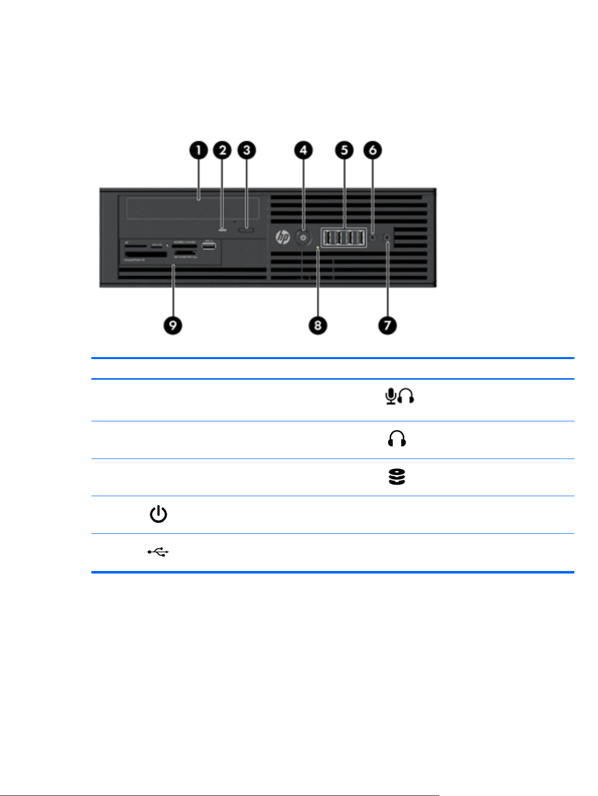
The following figure shows the front panel of an HP Z210 CMT Workstation. Drive configurations can
vary.
Figure 2-2 HP Z210 Workstation front panel
Table 2-2 HP Z210 CMT Workstation front panel connectors
Item Symbol Description Item Symbol Description
1 Optical drive manual eject 6
2 Optical drive eject button 7
3
4
5
Power button 8 1394a connector (optional and
Hard drive activity light 9 Optical drive activity light
USB 2.0 ports (3) 10 Optical drive
Headphone connector
Microphone connector
plugged unless configured)
ENWW
HP Z210 CMT Workstation components
9
Page 18

HP Z210 CMT Workstation rear panel components
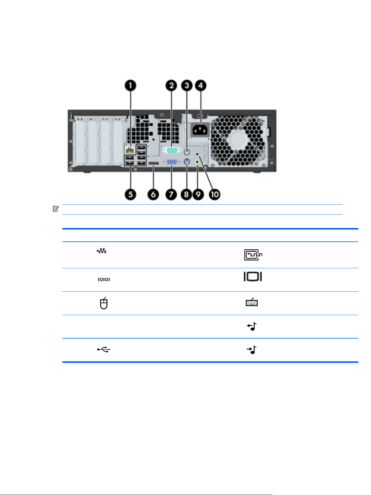
The following figure shows the rear panel of a typical HP Z210 CMT Workstation.
Figure 2-3 HP Z210 CMT Workstation rear panel
NOTE: The labels for the rear panel connectors use industry-standard icons and colors.
Table 2-3 Rear panel components
Item Symbol Description Item Symbol Description
1 Power supply fan 8
2
3 Universal chassis clamp opening 10
4 Cable lock slot 11
5 Padlock loop 12
6
7
PS/2 mouse connector (green) 9 Microphone connector (pink)
RJ-45 network connector 13 DVI-I connector
Audio line-in connector (blue) 14 PS/2 keyboard connector (purple)
Audio line-out connector (green)
USB 2.0 ports (4)
USB 2.0 ports (2)
Display Port (DP) connector
15 Power cord connector
10 Chapter 2 Workstation components ENWW
Page 19

HP Z210 SFF Workstation components
This section describes HP Z210 Small Form Factor (SFF) Workstation components, including front and
rear panel connectors.
For complete and current information on supported accessories and components for the computer, see
http://partsurfer.hp.com.
HP Z210 SFF Workstation chassis components
The following figure shows the chassis components of a typical HP Z210 SFF Workstation layout. Drive
configurations can vary.
Figure 2-4 HP Z210 SFF Workstation chassis components
ENWW
Table 2-4 Workstation component descriptions
Item Description Item Description
1 Access panel 8 System fan
2 Processor (CPU) 9 Chassis
3 Heatsink 10 Front bezel
4 Memory module (DIMM) 11 Speaker
5 System board 12 Optical drive
6 Hard disk drive 13 Optional media reader or second
hard disk drive
7 Airflow guide 14
HP Z210 SFF Workstation components
11
Page 20
HP Z210 SFF Workstation front panel components
The following figure shows the front panel of an HP Z210 SFF Workstation. Drive configurations can
vary.
Figure 2-5 HP Z210 Workstation front panel
Table 2-5 Front panel components
Item Symbol Description Item Symbol Description
1 Optical drive 6
2 Optical drive activity light 7
3 Optical drive eject button 8
4
5
Power button 9 Optional media card reader or second
USB 2.0 ports (4)
Microphone or headphones connector
(software selectable, default mode is
microphone)
Headphones connector
Hard drive activity light
hard disk drive
12 Chapter 2 Workstation components ENWW
Page 21
HP Z210 SFF Workstation rear panel components
The following figure shows the rear panel of a typical HP Z210 SFF Workstation.
Figure 2-6 HP Z210 SFF Workstation rear panel
NOTE: The labels for the rear panel connectors use industry-standard icons and colors.
Table 2-6 Rear panel components
Item Symbol Description Item Symbol Description
1
2
3
4 Power cord connector 9
5
RJ-45 network connector 6 Display Port (DP)
Serial port 7 VGA monitor output
PS/2 mouse connector (green) 8 PS/2 keyboard connector (purple)
Audio line-out connector (lime green)
USB 2.0 ports (6) 10 Audio line-in connector (blue)
ENWW
HP Z210 SFF Workstation components
13
Page 22

3 Setting up the workstation
This chapter describes how to set up the workstation, and includes these topics:
Topics
Ensuring proper ventilation on page 14
Setup procedures on page 15
Converting to desktop configuration on page 17
Adding monitors on page 19
Accessibility on page 24
Security on page 24
Product recycling on page 24
Ensuring proper ventilation
Proper ventilation for the system is important for workstation operation. Follow these guidelines to
ensure adequate ventilation:
Operate the workstation on a sturdy, level surface.
●
Place the workstation in an area with adequate ventilation. Provide at least 15.24 cm (6 inches) of
●
clearance at the front and back of the workstation as shown in the following figure.
Your workstation might look different than the one shown.
Figure 3-1 Proper workstation ventilation
Ensure that the ambient air temperature surrounding the workstation falls within the published limit.
●
14 Chapter 3 Setting up the workstation ENWW
Page 23

NOTE: The ambient upper limit of 35 C is only good up to 1524 m (5000 ft) elevation. There is
a 1 C per 304.8 m (1000 Fft derating above 1524 m (5000 ft). So, at 3,048 m (10,000 ft), the
upper ambient air temperature limit is 30 C.
For cabinet installation, ensure adequate cabinet ventilation and ensure that the ambient
●
temperature within the cabinet does not exceed published limits.
Never restrict the incoming or outgoing airflow of the workstation by blocking any vents or air
●
intakes as shown in the following figure.
Figure 3-2 Proper workstation placement
Setup procedures
WARNING! To reduce the risk of electric shock or damage to your equipment:
— Do not disable the power cord grounding plug. The grounding plug is an important safety feature.
— Plug the power cord in a grounded (earthed) outlet that is easily accessible.
To set up the workstation:
1. After unpacking your workstation, find workspace with the proper ventilation to set up the system.
2. Connect the mouse and keyboard to the workstation.
For connector location information, see the rear panel connector section for the workstation in this
document.
ENWW
Setup procedures
15
Page 24

3. Connect the power cord:
Figure 3-3 Connecting the power cord
WARNING! To reduce the risk of electric shock or damage to your equipment, observe these
practices:
• Plug the power cord into an AC outlet that is easily accessible.
• Disconnect power from the computer by unplugging the power cord from the AC outlet (not by
unplugging the power cord from the computer).
• If provided with a three-pin attachment plug on your power cord, plug the cord into a grounded
(earthed) three-pin outlet. Do not disable the power cord grounding pin, for example, by attaching
a two-pin adapter. The grounding pin is an important safety feature.
NOTE: After setting up the workstation hardware, connect other peripheral components (such as a
printer) according to the instructions included with the device.
16 Chapter 3 Setting up the workstation ENWW
Page 25

Converting to desktop configuration
The Z210 Convertible Mini Tower (CMT) Workstation can be operated in the mini-tower or the desktop
configuration. Follow these steps to convert to desktop configuration operation:
NOTE: See the workstation Maintenance and Service Guide for installation details for the following
steps.
1. Prepare the workstation for component installation (see Preparing the workstation for component
installation on page 34).
2. Remove the front bezel from the workstation.
3. Press gently on the edges of the optical drive bay filler panel, and remove it from the front bezel
as shown in the following figure.
Figure 3-4 Removing the ODD bay filler panel
4. Rotate the filler panel 90 degrees to a horizontal position.
5. Align the slots in the filler panel frame with the tabs in the front bezel. Press the optical drive filler
panel back into the front bezel until it snaps into place as shown in the following figure.
Figure 3-5 Installing the ODD bay filler panel
ENWW
Converting to desktop configuration
17
Page 26
6. On the back of the front bezel, squeeze the HP logo mounting tabs (1) and press the logo outward
(2) as shown in the following figure.
Figure 3-6 Rotating the HP logo
Rotate the HP logo 90 degrees counterclockwise, and then release the logo and press it back into
place in the front bezel.
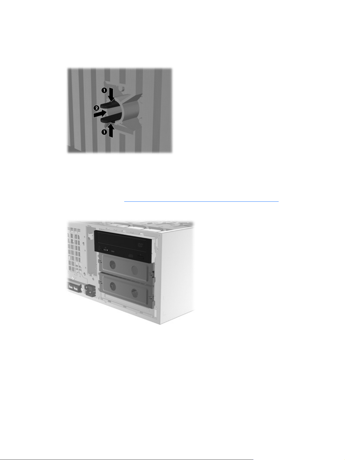
7. Remove the EMI filler panels and remove the optical disk drive from the chassis.
8. Rotate the EMI filler panels and the optical drive 90 degrees as shown in the figure below, and
then reinstall them (see
Installing an optical drive (desktop configuration) on page 55.
Figure 3-7 Reinstalling the optical drive
9. Replace the front bezel and the side access panel when finished.
18 Chapter 3 Setting up the workstation ENWW
Page 27

Adding monitors
This section describes how to connect monitors to the workstation.
Using workstation integrated graphics
Depending on CPU configuration, some HP Z210 CMT and SFF workstations support Intel® HD
Graphics (integrated graphics) with simultaneous output to two monitors. Refer to the workstation
Maintenance and Service Guide on the Web at
http://www.hp.com/go/workstations for additional information about your workstation.
or see
NOTE: If a PCIe or PCI graphics card is installed, Intel HD Graphics are disabled.
The HP Z210 CMT workstation provides rear-panel connectors for DisplayPort and DVI-I. (See HP Z210
CMT Workstation rear panel components on page 10.)
http://www.hp.com/support/workstation_manuals/,
The HP Z210 SFF workstation provides rear-panel connectors for DisplayPort and VGA. (See
SFF Workstation rear panel components on page 13.)
Planning for additional monitors
All graphics cards provided with HP Z Workstations support two simultaneous display monitors (see
Connecting the monitors on page 23). Other cards that support more than two monitors are
available. The process for adding monitors depends on your graphics card(s) and the type and number
of monitors you want to add.
Use this process to plan for adding more monitors:
1. Assess your monitor needs:
Determine how many monitors you require.
●
Determine the kind of graphics performance that you want.
●
Note the type of graphics connector used by each monitor. HP provides graphics cards with
●
DisplayPort (DP) and DVI interfaces, but you can use adapters and third-party cards to
interface to other graphics formats, including DVI-I, HDMI, or VGA.
TIP: Some adapters for older legacy hardware may cost more than others. You may want
to compare the cost of acquiring adapters versus the cost of getting a newer monitor that
doesn't need adapters.
HP Z210
ENWW
2. Determine if you need additional graphics cards:
Consult the graphics card documentation to determine how many monitors you can connect
●
to the card.
You may need to acquire adapters to match the card output to the monitor connector.
◦
(See
Matching graphics cards to monitor connectors on page 21.)
NOTE: Monitors with resolutions above 1920 x 1200 pixels at 60Hz require a graphics
card with either Dual Link DVI or Display Port output. To get native resolution with DVI,
however, you must use a DL-DVI cable, not standard DVI-I or DVI-D cables.
If necessary, plan to acquire a new graphics card to drive additional monitors.
●
Adding monitors
19
Page 28

NOTE: HP Z Workstations do not support all graphics cards. Make sure a new graphics
card is supported before purchasing it. To find out how to list supported graphics cards and
get other information, see
The maximum number of monitors that a graphics card supports depends on the card.
◦
Most cards provide outputs for two monitors, some graphics cards provide three or four
outputs.
NOTE: Many graphics cards provide more than two monitor outputs but limit you to
using only two at a time. Consult the graphics card documentation or look up
information on the card according to the procedure in
on page 21.
NOTE: Some graphics cards support multiple monitors by multiplexing the monitor
signal across multiple outputs. This may reduce graphics performance. Consult the
graphics card documentation or look up information on the card according to the
procedure in
Finding supported graphics cards on page 21.
Finding supported graphics cards on page 21.
Finding supported graphics cards
Make sure the card outputs match the input required by the monitors. (See
◦
monitor connection requirements on page 22.)
The different models of HP Z Workstations have different limits on the mechanical size,
◦
data speed, and power available for additional graphics cards. In addition, the usual
practical limit for graphics cards is two per computer. Refer to the
identification on page 41 section to make sure a new graphics card will work for your
computer.
3. If you find that you must add a new graphics card or cards:
a. Determine which HP-supported graphics card will best fit your needs in terms of number of
monitors, compatibility with the monitors you plan to use, and performance. To find out more
about supported graphics cards, see
b. Make sure you have the correct drivers for the graphics card.
c. Install the first graphics card as per the instructions in this manual. (See
devices on page 41.)
d. Configure the monitor in Windows (see
systems on page 23) or with a third-party configuration tool (see Using a third-party
graphics configuration utility on page 24).
TIP: To simplify troubleshooting of possible problems, enable the monitors one at a time,
i.e., enable the first monitor and then make sure the card, connections, and monitor all work
properly before enabling the next monitor.
Finding supported graphics cards on page 21.
Configuring the monitors using Microsoft® operating
Expansion card slot
Installing PCI/PCIe
Identifying
20 Chapter 3 Setting up the workstation ENWW
Page 29
Finding supported graphics cards
To find out more information about graphics cards supported for your workstation:
1. Go to:
http://www.hp.com/go/quickspecs
2. In the left hand navigation frame, under Quickspecs, click on your region (for example,
Worldwide).
3. After the page reloads, click on Workstations in the left hand navigation frame. This displays
an overview page for HP workstations.
4. Click on your workstation model, for example HP Z210 Workstation, choosing either HTML or
PDF.
5. In the document that is displayed, click on Technical Specifications-Graphics. This displays
expanded technical information for the graphics cards supported for your workstation.
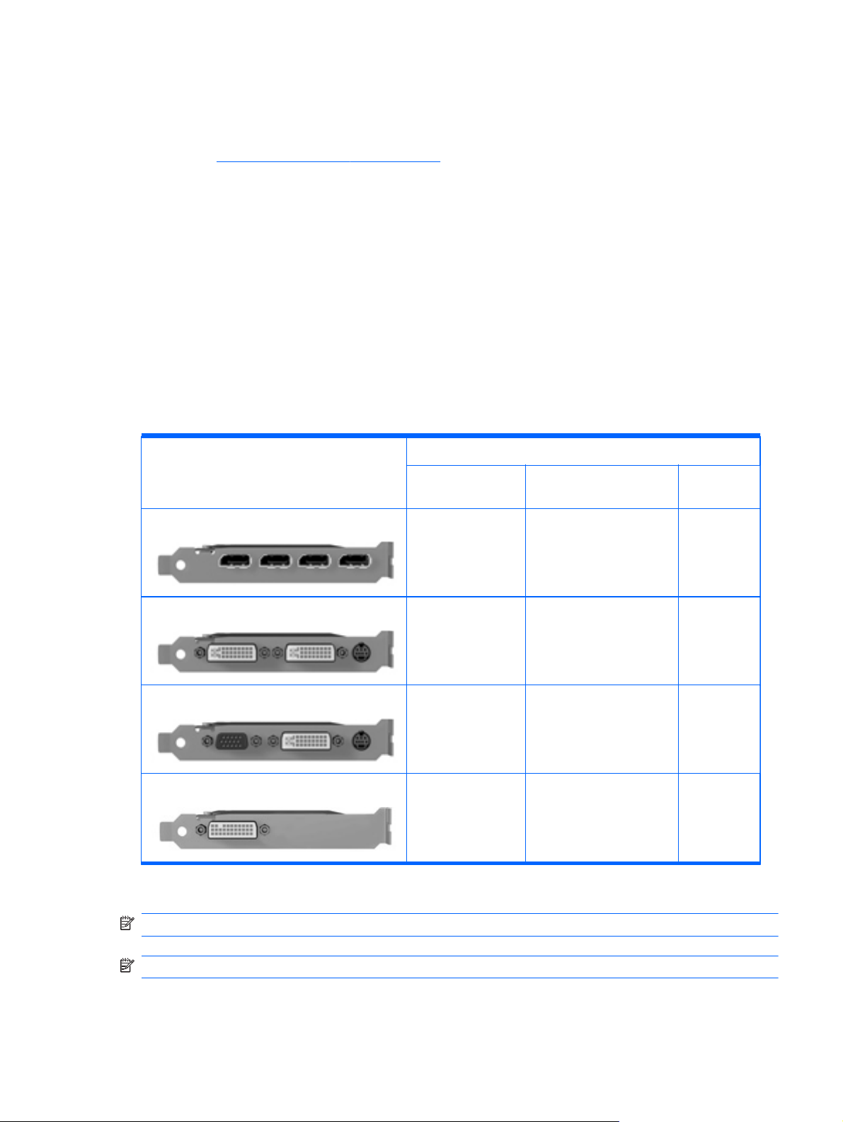
Matching graphics cards to monitor connectors
The following table describes monitor configuration scenarios.
Monitor connector
Graphics card interface connector
D
ISPLAYPORT
VGA DVI D
DisplayPort to VGA
adapter
(sold separately)
ISPLAYPORT
(DP)
DP to DVI adapter No adapter
required
DVI
VGA (
ON LEFT
)/DVI No adapter required No adapter required N/A
*
DMS-59
*
This interface is a dual-monitor graphics interface card that supports two VGA, two DVI or two DisplayPort monitors.
DVI to VGA adapter No adapter required N/A
DMS-59 to VGA
(sold separately)
DMS-59 to DVI DMS-59 to
DisplayPort
NOTE: HP graphics cards include monitor cable adapters unless otherwise indicated.
NOTE: VGA graphics cards have the lowest performance while DisplayPort cards have the highest.
ENWW
Adding monitors
21
Page 30

Identifying monitor connection requirements
The following are various scenarios for connecting monitors. (See Matching graphics cards to monitor
connectors on page 21 for more information about the different graphic cards):
Graphics card with DisplayPort output — If the workstation has a graphics card with four
●
DisplayPort output receptacles, you can connect a monitor to each receptacle. Use the proper
adapters if required.
Graphics card with DVI output — If the workstation has a PCIe graphics card with two DVI
●
output receptacles, you can connect a monitor to each DVI receptacle. Use the proper adapters if
required.
NOTE: Some HP Z workstations have only one DVI port. However, such workstations will always
have a second graphics output option (Display Port or VGA). Note also that many graphics cards
provide more than two monitor outputs but limit you to using only two at a time. Consult the
graphics card documentation or look up information on the card according to the procedure in
Finding supported graphics cards on page 21.
NOTE: Port number 1 on a system with two DVI connections provides the primary display,
which is where the POST and BIOS screens appear after a system restart. Usually, this is the lower
of the two outputs. (This can be changed in the BIOS settings.)
Graphics card with DMS-59 output — If the workstation has a PCIe graphics card with a
●
DMS-59 output receptacle, use the appropriate adapter to connect your monitors.
Adapters are available to connect the DMS-59 output to two DVI, two VGA, or two DisplayPort
monitors.
22 Chapter 3 Setting up the workstation ENWW
Page 31
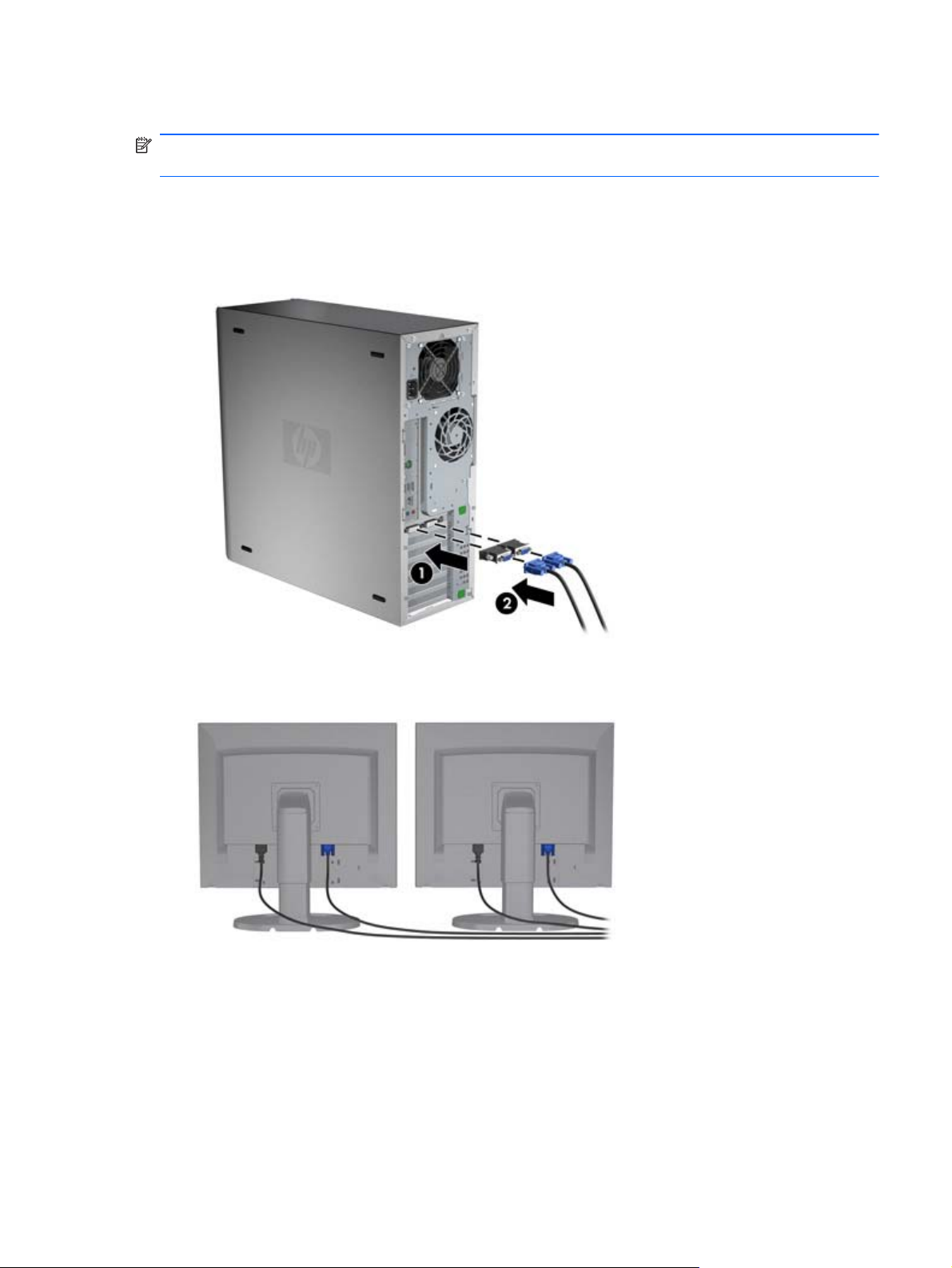
Connecting the monitors
NOTE: HP-supported graphics cards typically support at least two monitors, as shown in this section;
some supported cards support more monitors. Refer to the graphics card documentation for details.
1. Connect the monitor cable adapters (1) (if required) to the workstation, then connect the
appropriate monitor cables to the adapters (2) or directly to the graphics card, as shown in the
following figure.
Figure 3-8 Connecting the cables to the workstation
2. Connect the other ends of the graphics cables to the monitors as shown below.
Figure 3-9 Connecting cables to the monitors
3. Connect one end of the monitor power cord to the monitor and the other end to a grounded
power outlet.
Configuring the monitors using Microsoft® operating systems
Refer to Microsoft Help information or the Microsoft Web site for details about monitor configuration
procedures.
ENWW
Adding monitors
23
Page 32

Using a third-party graphics configuration utility
Third-party graphics cards may include a monitor configuration utility. Upon installation, this utility is
integrated into Windows. You can select the utility and use it to configure multiple monitors with your
workstation.
Refer to your graphics card documentation for instructions on using the monitor configuration utility.
NOTE: Some third-party configuration utilities require that you enable the monitors in Windows
before using the configuration tool. Refer to your graphics card documentation for more information.
NOTE: Monitor configuration utilities are also often available on the HP support Web site.
Refer to the Linux User Guide for instructions about using Linux to configure monitors with your
workstation.
Customizing the monitor display (Microsoft operating systems only)
You can manually select or change the monitor model, refresh rates, screen resolution, color settings,
font sizes, and power management settings.
To change display settings, right-click on the Windows Desktop, then click Screen resolution in
Microsoft® Windows® 7 Professional/Ultimate.
For more information about customizing your monitor display, see these resources:
Online documentation provided with the graphics controller utility
●
Documentation included with your monitor
●
Accessibility
HP is committed to developing products, services, and information that is easier to access for all
customers, including customers with disabilities and age-related limitations. HP products with
Microsoft® Windows preinstalled are designed for accessibility, and these products are tested with
industry-leading Assistive Technology products. See
information.
Security
Some HP workstations have a lock on the side access panel. The key for this lock is shipped attached to
the back panel of the workstation chassis.
The workstation includes several security features to reduce the risk of theft and to warn of chassis
intrusion. Refer to the Maintenance and Service Guide for information about additional hardware and
software security features available for your system.
Product recycling
http://www.hp.com/accessibility for more
HP encourages customers to recycle used electronic hardware, HP original print cartridges, and
rechargeable batteries.
For information about recycling HP components or products, see
24 Chapter 3 Setting up the workstation ENWW
http://www.hp.com/go/recycle.
Page 33

4 Setting up the operating system
This chapter provides setup and update information for the workstation operating system. It includes
these topics:
Topics
Setting up the Microsoft operating system on page 26
Setting up Red Hat Enterprise Linux on page 27
Setting up Novell SLED on page 28
Updating the workstation on page 29
This chapter also includes information on how to determine that you have the latest BIOS, drivers, and
software updates installed on the workstation.
CAUTION: Do not add optional hardware or third-party devices to the HP workstation until the
operating system is successfully installed. Adding hardware might cause errors and prevent the
operating system from installing correctly.
ENWW 25
Page 34

Setting up the Microsoft operating system
When you first apply power to the workstation, the operating system is installed. This process takes
approximately 5 to 10 minutes. Carefully follow the instructions on the screen to complete the
installation.
CAUTION: After installation has started, do not turn off the workstation until the process is complete.
Turning off the workstation during installation can damage the installation and operation of the
software.
For complete operating system installation and configuration instructions, see the operating system
documentation that was provided with the workstation. Additional information is available in the online
help tool after you successfully install the operating system.
Installing or upgrading device drivers
To install hardware devices after the operating system is installed, you must install the appropriate
device drivers before you install the devices. Follow the installation instructions that came with the
device. In addition, for optimum performance, your operating system must have the most recent
updates, patches, and software fixes. For additional driver and software update information, refer to
Upgrading device drivers on page 30.
Transferring files and settings to your Windows workstation
The Microsoft Windows operating system offers data migration tools that helps you choose and transfer
files and data from another Windows computer to your Windows operating system workstation.
For instructions on how to use these tools, see the documents at
http://www.microsoft.com.
26 Chapter 4 Setting up the operating system ENWW
Page 35

Setting up Red Hat Enterprise Linux
HP offers an HP Installer Kit for Linux (HPIKL) to supplement Red Hat box sets and help HP Linux
customers customize their system image. The HPIKL contains the HP driver CD and device drivers to
successfully setup up the Red Hat Enterprise Linux (RHEL) operating system, The HP Installer Kit for Linux
CDs are currently available for download at
To use the drivers in the HP Installer kit for Linux other than RHEL, you must manually extract the drivers
from the HP Driver CD and install them. HP does not test the installation of these drivers on other Linux
distributions nor does HP support this operation.
Verifying hardware compatibility
To see which Linux versions have been qualified to work on HP Workstations visit http://www.hp.com/
support/linux_hardware_matrix.
Installing from RHEL optical media
When installing RHEL on your workstation, follow this procedure prior to booting and installing from the
RHEL box set media:
1. With the RHEL install media in the DVD drive, restart the workstation and press the F9 key within
three seconds to display the boot menu. If you miss the boot menu, press Ctrl-Alt-Del to restart
and wait slightly more or less before pressing F9.
http://www.hp.com/support/workstation_swdrivers.
2. From the list of available boot sources, under Legacy boot sources, pick the optical drive that
contains the RHEL install media.
NOTE: Be sure to pick from the list labeled Legacy boot sources when selecting the optical
drive from which to boot. Do not select from UEFI boot sources. Doing so may result in the OS
installation being unable to complete.
3. Press Enter to continue with system boot and the OS installation process.
Installing with the HP driver CD
To install the HP driver CD, see “Installing with the HP Installer Kit for Linux” in the HP Workstations for
Linux manual at
http://www.hp.com/support/workstation_manuals.
ENWW
Setting up Red Hat Enterprise Linux
27
Page 36

Setting up Novell SLED
HP offers an HP Installer Kit for Linux (HPIKL) to help HP Linux customers customize their system image.
The HPIKL contains the HP driver CD and device drivers to successfully setup up the SUSE Linux
Enterprise Desktop (SLED) operating system. The HP Installer Kit for Linux CDs are currently available for
download at
Setting up SLED on preloaded systems
To set up the SUSE Linux Enterprise Desktop (SLED) on systems preloaded with the operating system:
1. Boot the workstation.
2. Start the Installation Settings and enter the password, network, graphics, time, keyboard settings,
and Novell Customer Center Configuration for the workstation.
NOTE: During Installation Settings after the first time after booting the system the Novell
subscription can be activated from the Novell Customer Center Configuration screen. Visit the full
Novell Customer Center documentation at
Installing from SLED optical media
To install SLED on your workstation, follow this boot procedure prior to installing from the SLED media:
1. With the SLED install media in the DVD drive, restart the workstation and press the F9 key within
three seconds to display the boot menu. If you miss the boot menu, press Ctrl-Alt-Del to restart
and wait slightly more or less before pressing F9.
http://www.hp.com/support/workstation_swdrivers.
http://www.novell.com/documentation/ncc/.
2. From the list of available boot sources, under Legacy boot sources, pick the optical drive that
contains the SLED install media.
NOTE: Be sure to pick from the list labeled Legacy boot sources when selecting the optical
drive from which to boot. Do not select from UEFI boot sources. Doing so may result in the OS
installation being unable to complete.
3. Press Enter to continue with system boot and the OS installation process.
Installing with the HP driver CD
To install the HP driver CD, see “Installing with the HP Installer Kit for Linux” in the HP Workstations for
Linux manual at
http://www.hp.com/support/workstation_manuals.
28 Chapter 4 Setting up the operating system ENWW
Page 37

Updating the workstation
HP is constantly working on improving your total workstation experience. To ensure that the workstation
leverages the latest enhancements, HP recommends that you install the latest BIOS, driver, and software
updates on a regular basis.
Updating the workstation after first boot
After successfully booting the workstation for the first time, you should follow these guidelines to ensure
that the workstation is up-to-date:
Ensure that you have the latest system BIOS loaded. See
●
instructions.
Ensure that you have the latest drivers for your system. See
●
on page 30 for instructions.
Become familiar with your available HP resources.
●
Consider a subscription to Driver Alerts at
●
Upgrading the BIOS
For optimum performance, determine the BIOS revision on the workstation, and upgrade it if necessary.
Determining current BIOS
To determine the current BIOS of the workstation during system power up:
1. Wait for F10=setup to appear on the lower right corner of the screen.
2. Press F10 to enter the F10 Setup utility.
The F10 Setup utility displays the workstation BIOS version under File > System Information.
3. Note the workstation BIOS version so that you can compare it with the BIOS versions that appear
on the HP website.
Upgrading the BIOS on page 29 for
Upgrading device drivers
http://www.hp.com/go/subscriberschoice.
ENWW
Updating the workstation
29
Page 38

Upgrading BIOS
To find and download the latest available BIOS, which includes the latest enhancements:
1. Go to
2. Select Download Drivers and Software from the left menu column under Tasks.
3. Follow the instructions to locate the latest BIOS available for the workstation.
4. If the BIOS on the Web site is the same as the version on your system, no further action is
5. If the BIOS on the Web site is a version later than the one on your system, download the
http://www.hp.com/go/workstationsupport.
required.
appropriate version for the workstation. Follow the instructions in the release notes to complete the
installation.
Upgrading device drivers
If you install a peripheral device (such as a printer, display adapter, or network adapter), confirm you
have the latest device drivers loaded. If you purchased your device through HP, visit the HP Web site to
download the latest drivers for your device. These drivers have been tested to ensure the best
compatibility between your device and your HP workstation.
If you did not purchase your device from HP, HP recommends visiting the HP Web site first to see if
your device and its drivers have been tested for HP workstation compatibility. If no driver is available,
visit the device manufacturer's Web site to download the latest drivers.
To upgrade device drivers:
1. Go to
2. Select Download Drivers and Software from the left menu column under Tasks.
3. Follow the instructions to find the latest drivers available for the workstation.
If a needed driver is not found, see the Web site of the manufacturer of the peripheral device.
http://www.hp.com/go/workstationsupport.
30 Chapter 4 Setting up the operating system ENWW
Page 39

5 Restoring the operating system
This chapter describes how to restore the Windows or Linux operating system. It includes these topics:
Topics
Restore method on page 31
Ordering backup software on page 32
Restoring Windows 7 on page 32
Restoring Novell SLED on page 33
Restore method
The Windows 7 operating system can be reinstalled using the HP Recovery Manager
HP Recovery Manager reinstalls the Windows operating system and device drivers (for devices
included with the system) to a near-factory state. The process does not back up or recover data on the
hard drive. Some application software might not be restored using this process and must be installed
from the appropriate application CD.
CAUTION: This method restores the operating system, but not data. Data must be backed up
regularly to avoid loss.
ENWW
Restore method
31
Page 40

Ordering backup software
You can order a recovery disk set from the HP support center. To obtain the support center telephone
number for your region see
64-bit system recovery media kit.
http://www.hp.com/support/contactHP. Request the Windows 7 32-bit or
Restoring Windows 7
This section describes how to restore Windows 7.
Ordering the HP Recovery Manager media
If you ordered restore media with your workstation, the media is included with your workstation
components.
If you did not order restore media, call HP Support and request the Windows 7 32-bit or 64-bit system
recovery media kit. For worldwide technical support phone numbers, see
Restoring the operating system
NOTE: Windows 7 provides a backup and restore application as well. To learn more about this
application, see the Microsoft Web site.
CAUTION: Before you restore the operating system, back up your data.
http://www.hp.com/support.
When you run HP Recovery Manager from media, the process deletes all information on the primary
hard drive, including all partitions.
To restore Windows 7:
1. Boot from the first disk in the HP Recovery Manager DVD set to start the system recovery process.
2. Follow the prompts to restore your operating system.
Some application software might not be restored using this process. If software is not restored, install it
from the appropriate application DVD.
32 Chapter 5 Restoring the operating system ENWW
Page 41

Restoring Novell SLED
The SLED restore media is required to restore the Linux operating system.
Creating restore media
The SUSE Linux Enterprise Desktop preload includes a SUSE ISO icon on the desktop. You can click this
icon to go to the /iso directory. The /iso directory contains all iso images used to preload your
workstation. To recover or restore the original image, follow the instructions in the readme file in the /
iso directory to copy the ISO image file onto CDs.
NOTE: Make copies of the ISO recovery images on CD as backup files in case your workstation
experiences a hard drive failure.
ENWW
Restoring Novell SLED
33
Page 42

6 Preparing for component
installation
To facilitate the installation of components, several steps can be taken to prepare the workstation. This
section describes how to prepare your workstation for component installation.
Disassembly and installation preparation
Use the following table to determine the order of workstation disassembly required before installing
components. (Your workstation components may be different than those listed.)
Table 6-1 Workstation component installation
To install... Remove... Then remove... Then... Then...
Memory
Expansion card (PCI/
PCIe)
Hard drive Chassis locks Side access panel Rotate front drive cage
Optical drive Chassis locks Side access panel Remove front bezel
*
See the workstation Maintenance and Service Guide for chassis lock locations and operation instructions.
Chassis locks
Chassis locks Side access panel
*
Side access panel
to upward position
(Z210 SFF)
Preparing the workstation for component installation
To prepare the workstation:
NOTE: The workstation contains green plastic touch points at locations where you must manipulate a
button or lever. Green touch points on some components indicate tool-less removal of those
components.
1. Disconnect power from the system.
2. Unlock the side access panel or remove any chassis locks.
Rotate power supply
to upright position
(Z210 SFF)
3. Remove the side access panel as shown in the following illustrations.
34 Chapter 6 Preparing for component installation ENWW
Page 43

Z210 CMT Z210 SFF
Pull up on the handle (1), slide the cover 1.27 cm (0.5
inches) toward the rear of the system (2), then rotate the
cover off the chassis (3).
Lift the side access panel handle (1), and remove the side
access panel (2).
4. Raise the expansion card retention clamp and remove the expansion card slot cover as shown in
the following illustrations, if applicable.
Z210 CMT Z210 SFF
Open the card retention clamp by pressing down at the
green touch points (1), and then lift the slot cover from the
chassis (2).
Lift the card retention clamp at the green touch point to
open it, then lift the slot cover from the chassis.
ENWW
Preparing the workstation for component installation
35
Page 44

5. (HP Z210 CMT only) Remove the front bezel as shown in the following illustration.
Lift the release tabs (1), and then rotate the front bezel off the chassis (2).
6. (HP Z210 SFF only) Rotate the front drive cage to the upright position.
36 Chapter 6 Preparing for component installation ENWW
Page 45

7. (HP Z210 SFF only) Rotate the power supply to its upright position.
The workstation is now prepared for the component installation procedures described in the chapters
that follow.
ENWW
Preparing the workstation for component installation
37
Page 46
7 Installing memory
This section describes how to add memory to your workstation.
Supported memory configurations
Refer to the quick specs at http://www.hp.com/go/productbulletin for specific DIMM compatibility
information for HP workstations.
NOTE:
— Install only HP-approved, unbuffered DDR3 DIMMs.
— HP Z210 CMT and SFF Workstations support Error Checking and Correcting (ECC) and non-ECC
DIMM memory modules.
— Do not intermix ECC and non-ECC memory. The system will not boot and will produce a memory
error.
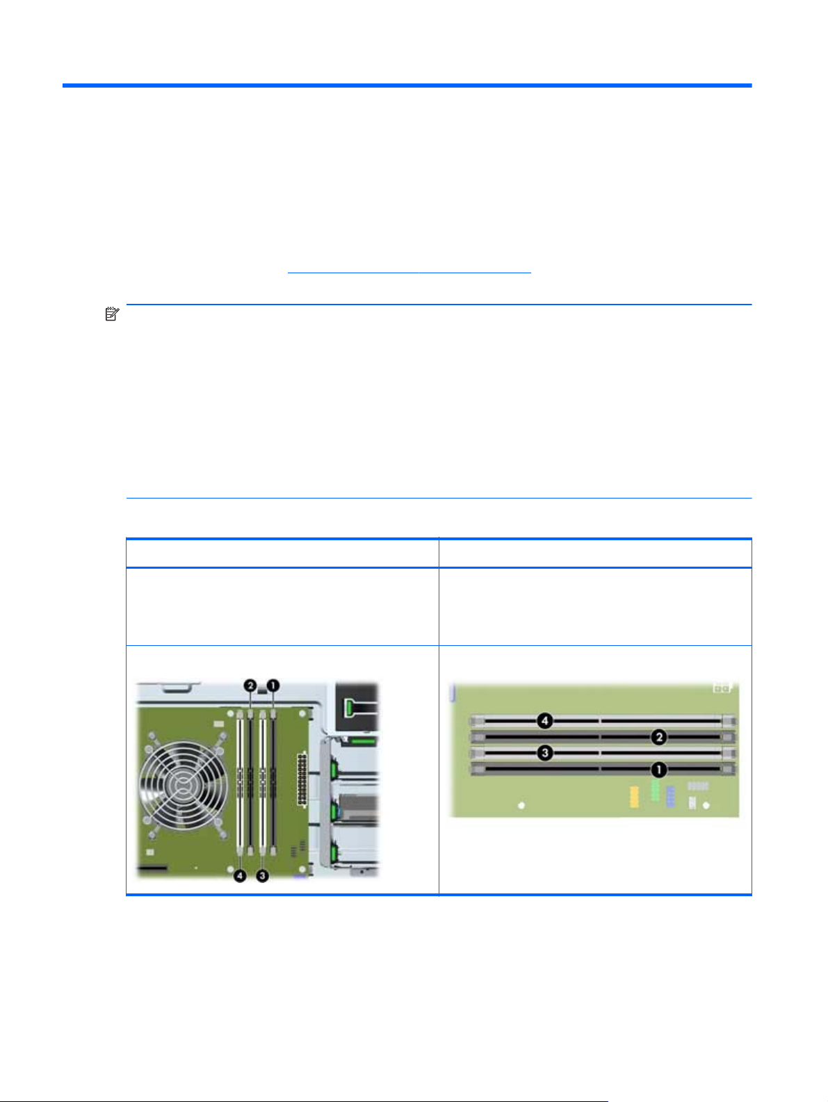
— For maximum performance, install DIMM memory modules in pairs of the same size.
— Install DIMM memory modules in the order shown below.
The following table describes the memory configurations supported by the HP Z210 Workstations.
Z210 CMT Z210 SFF
Supported configurations
Four DIMM slots
●
Memory configuration from 1 GB to 32 GB
●
DIMM installation order
Supported configurations
Four DIMM slots
●
Memory configuration from 1 GB to 32 GB
●
DIMM installation order
38 Chapter 7 Installing memory ENWW
Page 47

Installing a DIMM
To install a DIMM:
1. Follow the procedures described in
the workstation for component installation.
2. Push gently outward on the DIMM socket levers as shown in the following illustration.
Figure 7-1 Opening DIMM socket levers
Preparing for component installation on page 34 to prepare
3. Align the DIMM connector key with the DIMM socket key, and then seat the DIMM firmly in the
socket (1) as shown in the following illustration.
CAUTION: DIMMs and their sockets are keyed for proper installation. To prevent socket or
DIMM damage, align these guides properly when installing DIMMs.
Figure 7-2 Seating the DIMM
ENWW
Installing a DIMM
39
Page 48

4. Secure the socket levers (2).
5. Replace all components that were removed in preparation for component installation.
40 Chapter 7 Installing memory ENWW
Page 49

8 Installing PCI/PCIe devices
This section describes how to install a PCI or PCIe card in the workstation. To increase the performance
and functionality of your system, PCI/PCIe devices such as graphics cards or audio cards can be
installed in the expansion card slots on the workstation.
Expansion card slot identification
The following tables describe the expansion card slots in the HP Z210 Workstations.
Z210 CMT Z210 SFF
Slot description Slot power Slot description Slot power
1–PCIe2 - x8(4) 25W 1–PCI 32b/33Mhz 25W
2–PCIe2 - x16 75W 2–PCIe2 - x16 45W
3–PCIe2 - x1 10W 3–PCIe2 - x16 (4) 25W
4–PCIe2 - x16(4) 25W 4–PCIe2 - x1 10W
5–PCIe2 - x1 10W
6–PCI 32b/33Mhz 25W
7–PCI 32b/33Mhz 25W
NOTE: The x1, x4, x8, and x16 designators describe the mechanical (physical) length of the slot.
The number in parentheses lists the number of electrical PCIe lanes routed to the expansion slot. For
example, x8(4) means that the expansion slot is mechanically a x8 length connector, with four PCIe
lanes connected.
ENWW
Expansion card slot identification
41
Page 50

Power limitations for graphics cards
CAUTION: To prevent damage, the overall power consumption of the workstation (including I/O
cards, CPU, and memory) must not exceed the maximum rating of the workstation power supply.
When when planning, purchasing, and installing graphics cards in your workstation, observe the
following power limitations:
Z210 CMT
●
Maximum allowable graphics card power for Slot 2 is 150W. Note that 75W is available
◦
from the system board and an additional 75W directly from the PSU (using the 6–pin power
connector from the power supply). If a second graphics card is installed in Slot 4, the
combined power consumption of both cards must not exceed 150W.
NOTE: If you use a graphics card with greater than 75 watts of power, leave the adjacent
slot empty for thermal cooling considerations.
Slot 4 is mechanically x16 with four PCIe lanes connected; it supplies 25W of power. Do not
◦
exceed this power limitation when installing a second graphics card in this slot.
Z210 SFF
●
Maximum allowable graphics card power for Slot 2 is 45W. If a second graphics card is
◦
installed in Slot 3, the combined power consumption of both cards must not exceed 45W.
Overall power capacity of Slots 1 through 4 is 80W.
◦
Installing an expansion card
NOTE: The following procedure describes how to install an expansion card in a typical HP Z
workstation. Your workstation may look different.
To install a PCI or PCIe expansion card:
1. Follow the procedures described in
the workstation for component installation.
Preparing for component installation on page 34 to prepare
42 Chapter 8 Installing PCI/PCIe devices ENWW
Page 51

2. Align the card keyway with the slot key, and then firmly seat the card in the slot as shown in the
following illustration (1).
Figure 8-1 Installing an expansion card (Z210 CMT shown)
3. Close the retention clamp by rotating it downward (2) as shown in the illustration above.
NOTE: For the Z210 SFF Workstation, close the expansion slot retention clamp making sure all
cards are seated.
Figure 8-2 Closing the expansion card retention clamp (Z210 SFF)
4. Connect all necessary power and interface cables to the card (follow instructions that came with
the expansion card).
5. Replace all components removed in preparation for component installation.
ENWW
Installing an expansion card
43
Page 52

9 Installing hard disk drives
This section describes how to install a hard disk drive (HDD) in the workstation.
HDD configuration
The following table contains hard disk drive installation configuration information.
Z210 CMT Z210 SFF
HDD bays are designed to permit easy installation. Data cables are pre-connected in the workstation based on the factory
configuration delivered.
The workstation typically ships with an HDD, but additional drives can be added to expand data storage:
Refer to the service label on the side access panel of your workstation to determine the location of the SATA Gen 3 (6
●
Gbit/sec) and Gen 2 (3 Gbit/sec) ports.
Additional HDDs must be added in a specific sequence, depending on the type of workstation.
●
Once installed, the HDDs are assigned drive letters, with C:\ being the typical boot disk. Drive letters are assigned using
●
the Computer Setup (F10) Utility.
With additional HDDs installed, the workstation boot sequence can be modified so that the workstation boots from one of
●
the additional drives. Boot sequence is specified using the Computer Setup (F10) Utility.
With additional HDDs installed, you have hard disk space for additional programs, data files, and backup.
Refer to the workstation Maintenance and Service Guide at
many HDDs the workstation can accommodate, drive installation order, and boot sequencing procedures.
http://www.hp.com/support/workstation_manuals to learn how
44 Chapter 9 Installing hard disk drives ENWW
Page 53

Z210 CMT Z210 SFF
Drive and cable configuration
HDD bays are numbered 4 through 6 on the chassis. Each
HDD bay contains a mounting sled, allowing tool-less
installation and removal of hard disk drives.
The cables plug into the system board connectors in the
following manner:
SATA HDD cables plug into SATA ports starting at SATA
●
port zero.
Blue SATA ports (labeled zero and one) support SATA
●
Gen 3 (6 Gbit/sec). For best performance, use SATA
Gen 3 data cables to connect primary (SATA Gen 3)
hard disk drives to SATA ports zero and one.
HDD installation order
Drive and cable configuration
The HDD bays are not labeled on the chassis.
The cables plug into the system board connectors in the
following manner:
SATA HDD cables plug into SATA ports starting at SATA
●
port zero.
Blue SATA ports (labeled zero and one) support SATA
●
Gen 3 (6 Gbit/sec). For best performance, use SATA
Gen 3 data cables to connect primary (SATA Gen 3)
hard disk drives to SATA ports zero and one.
HDD installation order
Installing a hard disk drive
This section describes how to install a hard disk drive in the workstation.
Installing an HDD in an HP Z210 CMT Workstation
To install an HDD:
1. Follow the procedures described in
the workstation for component installation.
ENWW
Preparing for component installation on page 34 to prepare
Installing a hard disk drive
45
Page 54

2. Select a drive bay in which to install the hard disk drive and remove its mounting sled.
Figure 9-1 Removing the mounting sled
3. Install the HDD into the mounting sled as shown in the following figure.
Figure 9-2 Installing the HDD in the mounting sled
46 Chapter 9 Installing hard disk drives ENWW
Page 55

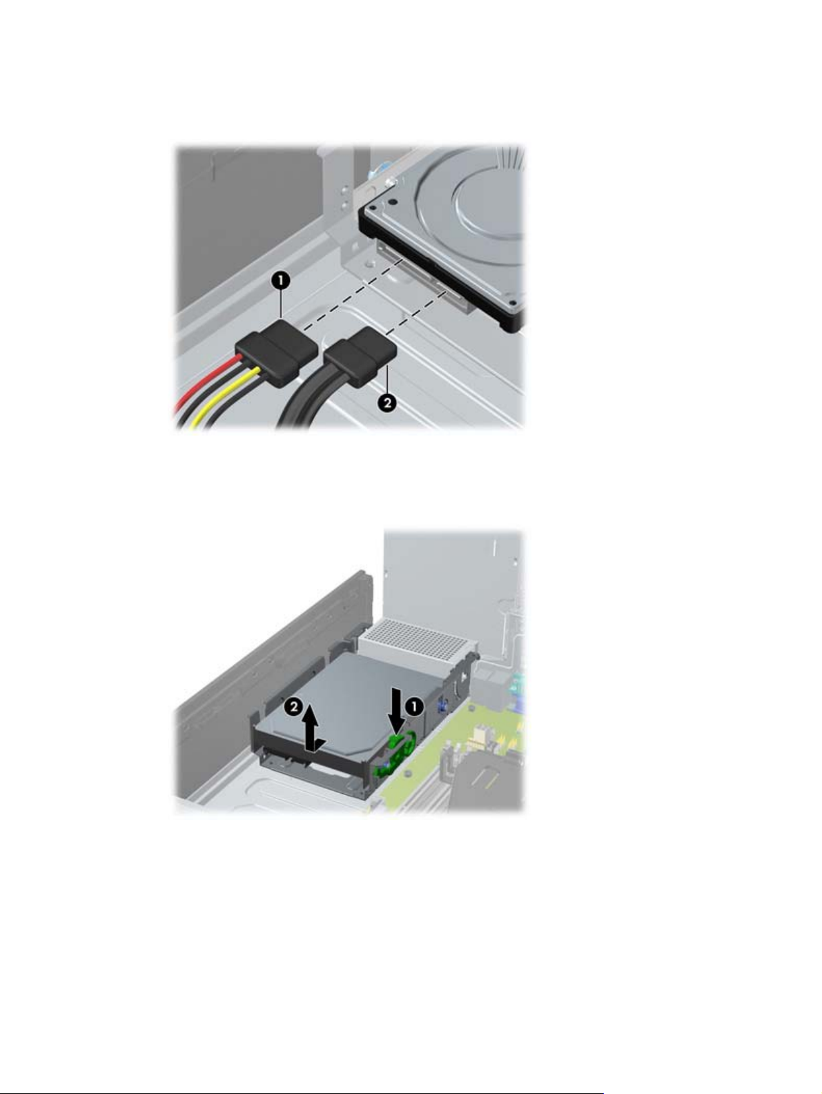
4. Push the sled containing the HDD into the selected bay until it snaps into place (1) as shown in the
following figure.
Figure 9-3 Installing the HDD drive
5. Attach a power cable (2), and a data cable (3), to the hard disk drive.
CAUTION: To avoid crushing or pinching the data cable when you replace the access panel,
use the HP-supplied data cable with right-angle connectors.
NOTE: Connect data cables to lower-numbered drive connectors first on the system board. To
identify hard disk drive ports, refer to the workstation service label on the side access panel.
NOTE: Blue SATA ports (numbered zero and one) support SATA Gen 3 (6 Gbit/sec).
6. Replace all components that were removed in preparation for component installation.
Installing an HDD in an HP Z210 SFF Workstation
To install an HDD:
1. Follow the procedures described in
the workstation for component installation.
Preparing for component installation on page 34 to prepare
ENWW
Installing a hard disk drive
47
Page 56

2. Rotate the drive cage to its upright position.
Figure 9-4 Rotating the Drive Cage Up
3. Rotate the power supply to its upright position. The hard drive is located beneath the power
supply.
Figure 9-5 Rotating the power supply up
48 Chapter 9 Installing hard disk drives ENWW
Page 57
4. Disconnect the power cable (1) and data cable (2) from the hard drive.
Figure 9-6 Disconnecting power and data cables from the primary HDD
5. Press down on the green release latch next to the hard drive (1). While holding the latch down,
slide the drive forward until it stops, then lift the drive up and out of the bay (2).
Figure 9-7 Removing the primary hard drive
ENWW
Installing a hard disk drive
49
Page 58

6. To install a new hard drive, move the silver and blue isolation mounting guide screws from the old
hard drive to the new hard drive.
Figure 9-8 Installing the hard drive guide screws
You can also install a 6.4 cm (2.5 in.) small form factor hard drive in the primary drive bay:
a. Transfer the silver and blue isolation mounting guide screws from the old hard drive to a
drive carrier.
b. Use the black M3 screws from the front of the chassis to mount the small form factor drive to
the carrier (2).
Figure 9-9 Attaching the drive to a carrier
50 Chapter 9 Installing hard disk drives ENWW
Page 59

7. Align the guide screws with the slots on the chassis drive cage, press the hard drive down into the
bay, then slide it back until it stops and locks in place.
Figure 9-10 Installing the hard drive (drive carrier shown)
8. Rotate the drive cage and the power supply down to their normal positions.
9. Replace all components that were removed in preparation for component installation.
Installing a secondary HDD or media card reader into a Z210 SFF
You can install an 8.89 cm (3.5 in) hard drive underneath the 13.3 cm (5.25 in) optical drive. A
media card reader can also be installed at this location. If an optical drive is present, you must remove
it to install the hard drive.
To install a hard drive or media card in the drive cage:
1. Follow the procedures described in
the workstation for component installation.
2. Remove the front bezel.
3. Remove the optical disk drive if it is present. (See
Workstation on page 56.)
Preparing for component installation on page 34 to prepare
Installing an optical drive in an HP Z210 SFF
ENWW
Installing a hard disk drive
51
Page 60
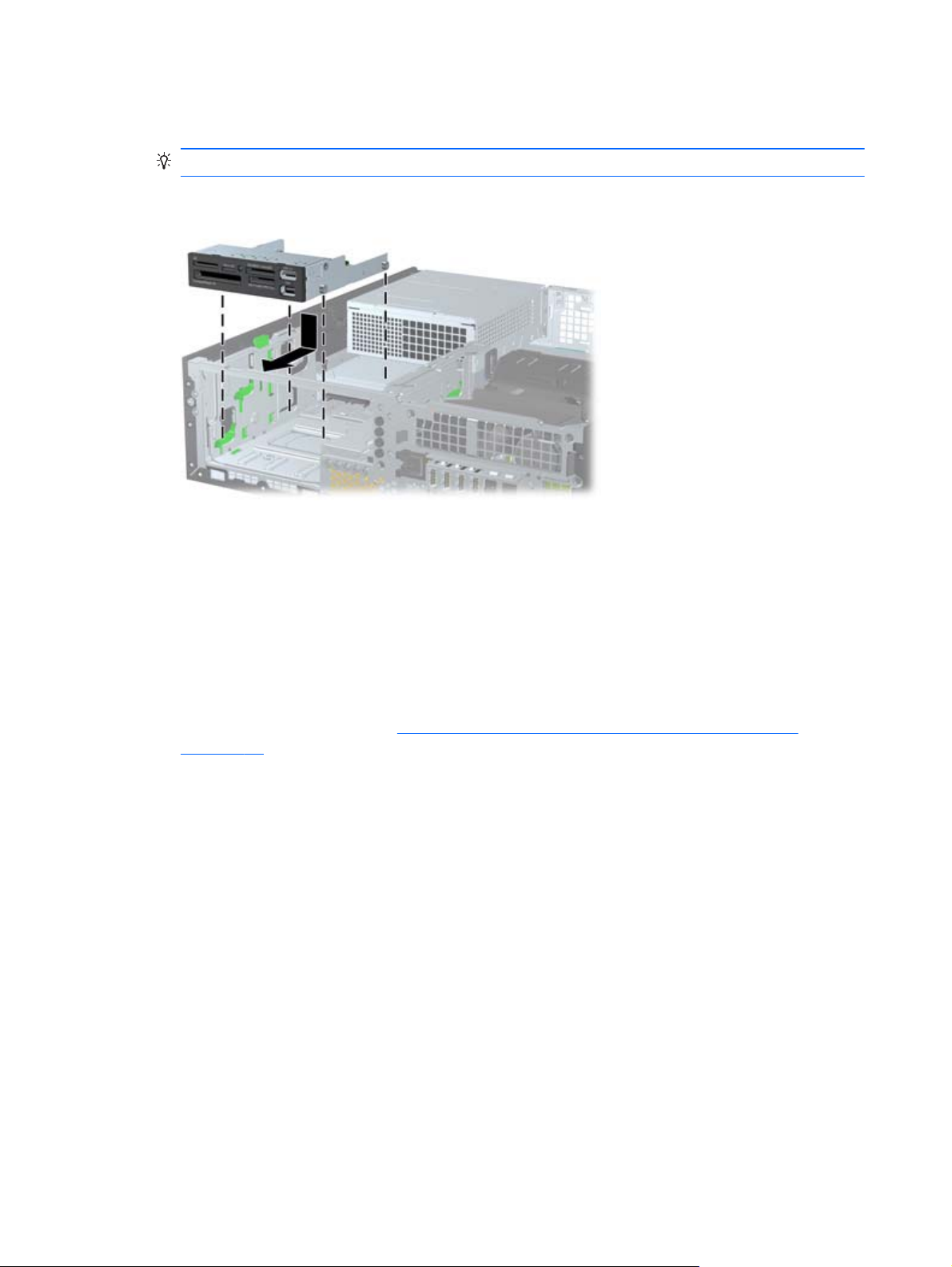
4. Place the drive's guide screws into the J-slots in the drive bay. Then slide the drive toward the front
of the computer until it locks into place.
TIP: Angle the drive toward one side of the chassis to line up the guide screws with the slots.
Figure 9-11 Installing a drive into the drive cage (media card reader shown)
5. Connect the drive cables:
a. If installing a second hard drive, connect the power and data cables to the rear of the drive
and connect the other end of the data cable to the next available (unpopulated) SATA
connector on the system board by following the numbered sequence of the connectors. To
identify hard disk drive ports, refer to the workstation service label on the side access panel.
b. If installing a media card reader, connect the USB cable from the media card reader to the
USB connector on the system board labeled MEDIA. If the media card reader includes a
1394 port, connect the 1394 cable to the 1394 PCI card.
6. Replace the optical drive. (See
on page 56.)
7. Replace the front bezel.
8. Replace the access panel.
9. Replace all components that were removed in preparation for component installation.
Installing an optical drive in an HP Z210 SFF Workstation
52 Chapter 9 Installing hard disk drives ENWW
Page 61
10 Installing optical disk drives
This section describes how to install an optical disk drive (ODD) in the workstation.
Installing an optical drive in an HP Z210 CMT Workstation
This section describes how to install an optical disk drive in the HP Z210 CMT Workstation in the minitower and desktop configurations.
Installing an optical drive (mini-tower configuration)
1. Follow the procedures described in Preparing for component installation on page 34 to prepare
the workstation for component installation.
2. If necessary, remove the EMI filler from the front of the optical bay.
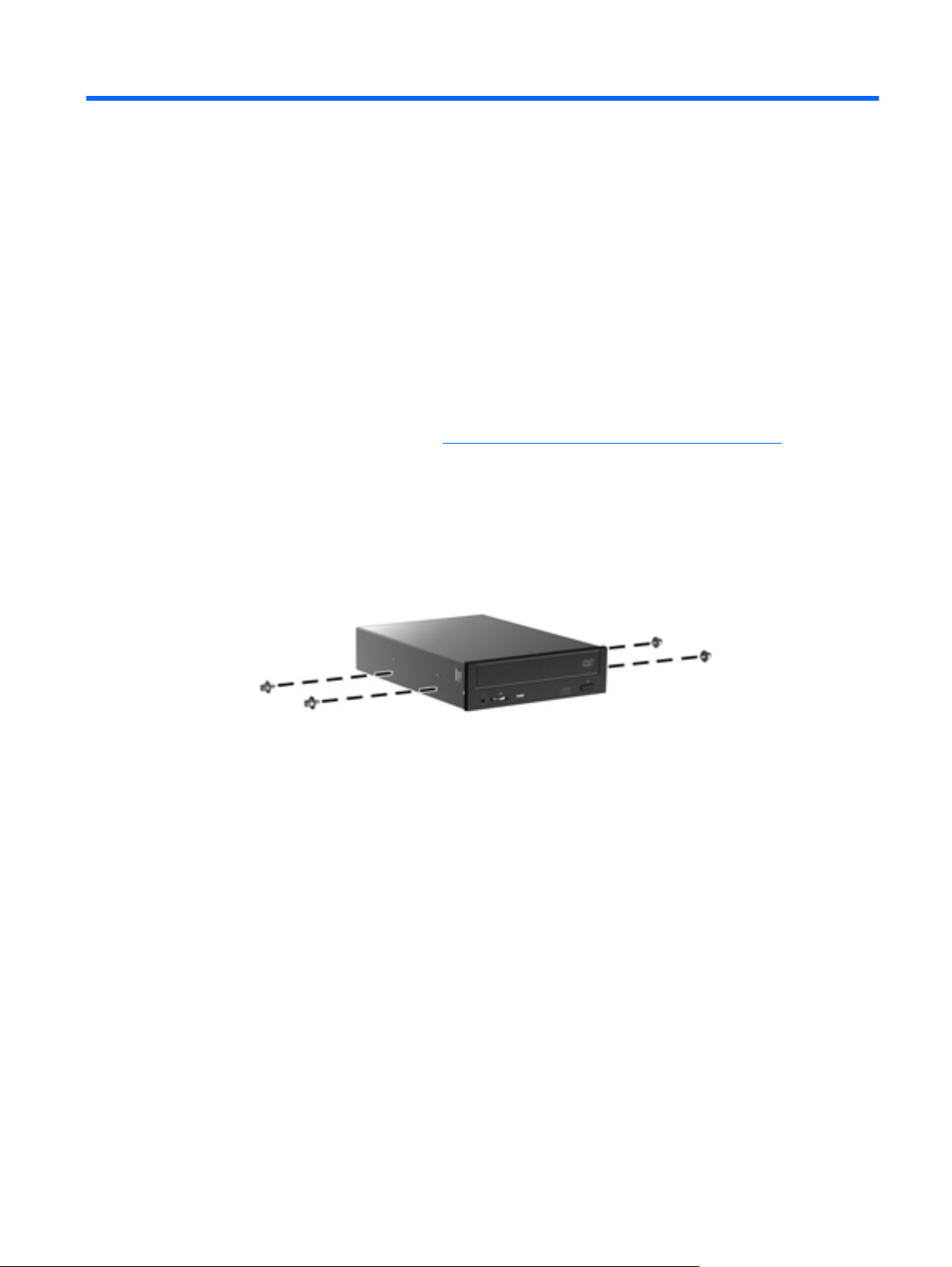
3. Install four black metric M3 guide screws into the drive. Spare metric M3 screws are stored on the
side of the drive bays.
Figure 10-1 Installing the guide screws
ENWW
Installing an optical drive in an HP Z210 CMT Workstation
53
Page 62

4. Align the screws with the grooves in the drive bay and gently slide the drive into the casing. Slide
the drive completely in until it snaps into place.
CAUTION: Verify that the optical disk drive is secure in the workstation chassis by pulling on
the drive to see if it can be easily disengaged. Failure to properly secure the drive can damage
the drive when moving the workstation.
Figure 10-2 Inserting the ODD into the casing
5. Connect the power and data cables to the optical disk drive and system board as shown in the
following figure. Refer to the side access panel service label for the location of the SATA
connectors. Connect the data cable in the next available connector.
Figure 10-3 Connecting ODD power and data cables
6. Replace all components that were removed in preparation for component installation.
54 Chapter 10 Installing optical disk drives ENWW
Page 63
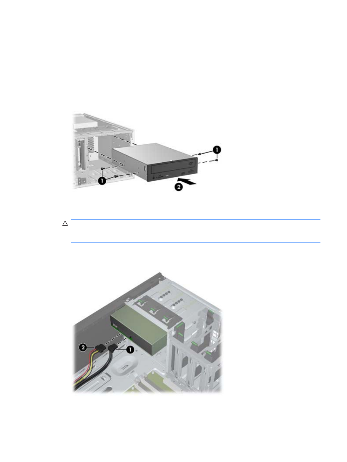
Installing an optical drive (desktop configuration)
1. Follow the procedures described in Preparing for component installation on page 34 to prepare
the workstation for component installation.
2. If necessary, remove the EMI filler from the front of the optical bay.
3. Install four black metric M3 guide screws into the drive (1). Spare metric M3 screws are stored on
the side of the optical bay.
Figure 10-4 Installing the optical drive
4. Align the screws with the grooves in the drive bay and gently slide the drive into the bay until it
snaps into place (2).
CAUTION: Ensure that the optical drive is secure in the workstation chassis by pulling the drive
to see if it can become disengaged. Failure to properly secure the drive can cause damage to the
drive when moving the workstation.
5. Connect the power and drive cables to the drive and system board.
Figure 10-5 Connecting the power and data cables
ENWW
Installing an optical drive in an HP Z210 CMT Workstation
55
Page 64

Installing an optical drive in an HP Z210 SFF Workstation
To install or re-install an optical drive in an HP Z210 SFF Workstation:
1. Follow the procedures described in
the workstation for component installation.
2. Remove the front bezel.
3. If necessary remove the bezel blank.
4. Install four M3 metric guide screws in the lower holes on each side of the drive. Either re-use the
screws used by your previous optical drive or use the extra HP-provided guide screws mounted on
the front of the chassis.
CAUTION: Use only 5-mm long screws as guide screws. Longer screws can damage the
internal components of the drive.
Figure 10-6 Installing Guide Screws in the Optical Drive
Preparing for component installation on page 34 to prepare
5. Position the guide screws on the drive into the J-slots in the drive bay. Then slide the drive toward
the front of the computer until it locks into place.
Figure 10-7 Installing the Optical Drive
56 Chapter 10 Installing optical disk drives ENWW
Page 65
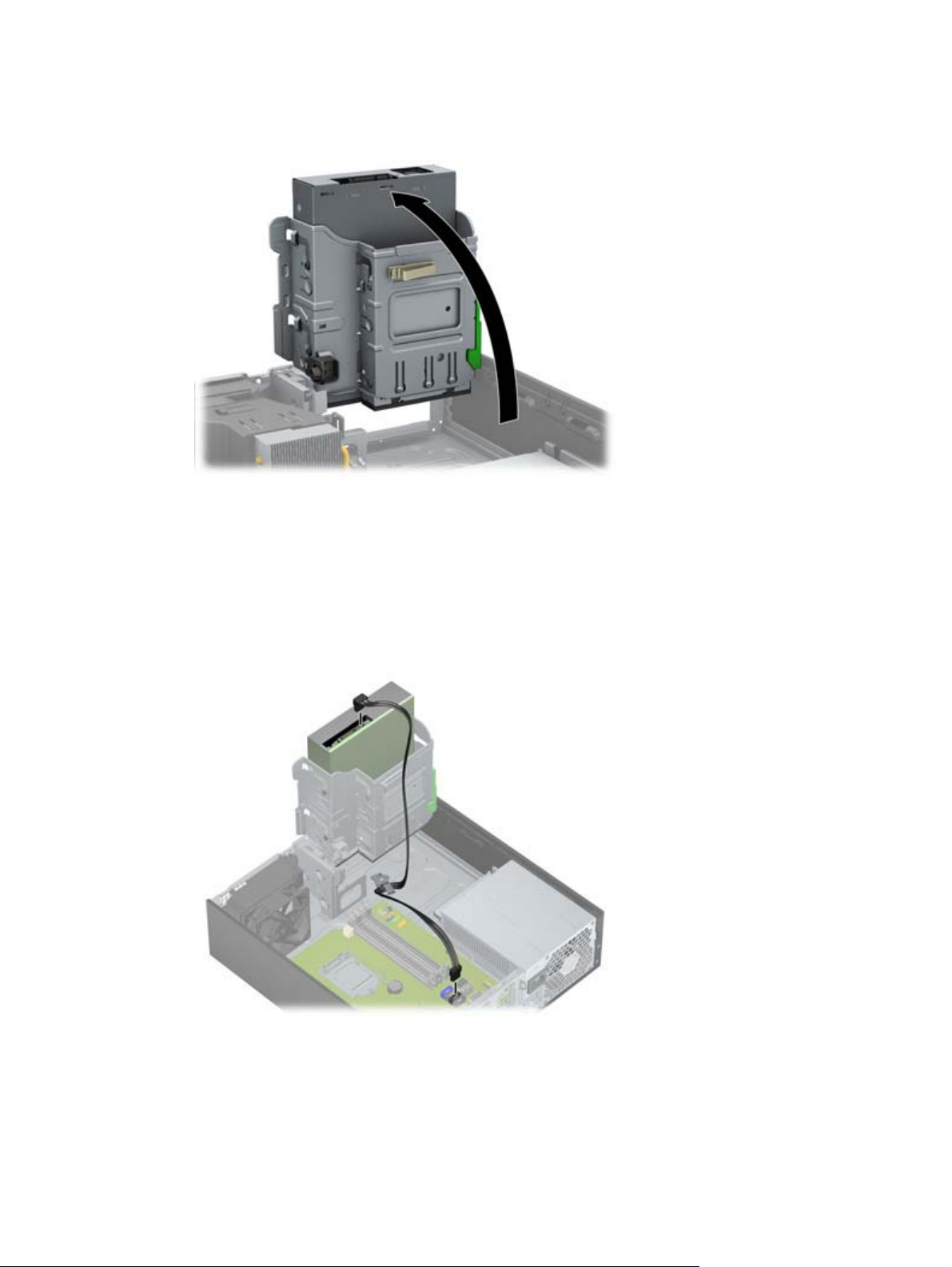
6. Rotate the drive cage to its upright position.
Figure 10-8 Rotating the Drive Cage Up
7. If a cable is not already present and connected, connect the SATA data cable to the system board
connector labeled SATA1.
Route the data cable through the cable guides. Two cable guides keep the data cable from being
pinched by the drive cage when raising or lowering it. One is located on the bottom side of the
drive cage. The other is part of the chassis frame under the drive cage. Ensure that the data cable
is routed through these guides before connecting it to the optical drive.
Figure 10-9 Routing the drive cable
ENWW
Installing an optical drive in an HP Z210 SFF Workstation
57
Page 66

8. Connect the power cable (1) and data cable (2) to the rear of the optical drive.
Figure 10-10 Connecting the power and data cables
9. Carefully rotate the drive cage back down to its normal position.
CAUTION: Be careful not to pinch any cables or wires when rotating the drive cage down.
10. Replace the front bezel with any bezel blanks removed as applicable.
11. Replace all components that were removed in preparation for component installation.
58 Chapter 10 Installing optical disk drives ENWW
Page 67

Notice for Blu-ray optical drives
If you installed a Blu-ray optical drive, note the following:
Blu-ray movie playback
As Blu-ray is a new format containing new technologies, certain disc, digital connection, compatibility
and/or performance issues may arise, and do not constitute defects in the product. Flawless playback
on all systems is not guaranteed. In order for some Blu-ray titles to play, they may require a DVI, HDMI,
or DisplayPort digital connection and your display may require HDCP support. HD-DVD movies cannot
be played on this workstation.
Blu-ray movie playback compatibility and update
Playing back Blu-ray HDCP (High-bandwidth Digital Content Protection) content such as commercially
distributed Blu-ray HD movies requires a fully HDCP compliant path on your computer. The HDCP
technology checks compliance of each component in the path from the content on the Blu-ray disc all
the way to the display monitor, including but not limited to graphic cards and monitor adapters.
HP Z Workstations have been designed with this in mind; nearly all configurations with currently
available HP Professional Displays are compliant. Older HP xw4600 and xw9400 Workstation
configurations may not have fully compliant paths based on the installed graphics card and display
monitor; HP recommends confirming separately that you have a fully compliant system if commercial
content playback is a requirement for your use. HDCP compatibility of your graphics card and monitor
can be determined by checking the QuickSpecs at
http://www.hp.com/go/productbulletin.
For the best HDCP performance, HP recommends that you install the latest updates:
1. Blu-ray player firmware
2. Playback application patches
3. Graphics firmware and drivers (note that the Intel HD graphics family does not support Blu-ray
movie playback on Windows XP nor on Linux.)
Updates are located on the support web site for your specific product at
workstations.
http://www.hp.com/support/
ENWW
Notice for Blu-ray optical drives
59
Page 68

Index
B
BIOS
Determining version 29
Updating 30
D
Drivers
Installing 26
Updating 26, 30
E
Expansion card
Installing 41
Slot identification 41
Expansion card support
Removing 34
Expansion slot cover
Removing 34
F
Front bezel
Removing 34
G
Graphics cards
Types 21
H
Hard drive
Configuration 44
Installing 44
Hardware
Disassembly 34
HP Recovery Manager 32
HP resources
Locating 1
Product diagnostics 5
Product documentation 4
Product information 2
Product support 3
Product updates 6
Web links 4
I
Installing
Expansion cards 41
Hard drive 44
hardware 34
Memory 39
Optical drive 53
PCI/PCIe cards 41
Installing memory 38
M
Memory
Installation 39
Memory fan
Removing 34
Microsoft Windows
Setting up 26
Transferring files 26
Monitors
Adjusting display 24
Configuring 23
Connecting 23
Graphics cards 21
N
Novell SLED
Restoring 33
Setting up 28
O
Operating system setup
Microsoft Windows 26
Red Hat Linux 27
Operating system setup; Novell
SLED 28
Optical drive
Installing 53
P
Product features
Computer components 7, 11
Front panel components 9, 12
Rear panel components 10,
13
R
Red Hat Linux
Setting up 27
Restoring the operating system
Restore method 31
S
Side access panel
Removing 34
Software
Ordering 32
Support
Locating HP resources 1
System fan
Removing 34
U
Updating the workstation
First boot update 29
Updating drivers 30
Updating the BIOS 30
W
Windows Vista
Setting up 26
Windows XP
Setting up 26
Workstation
Preparing for component
installation 34
Workstation components 7
Workstation setup
Accessibility 24
Connecting monitors 19
Customizing the display 24
Ensuring proper ventilation 14
Security 24
Setup procedures 15
60 Index ENWW
 Loading...