

Page 1

YELLOWJACKET
manual version 2.1
PLUS
Page 2

Contents
INTRODUCTION................................................................................................. 2
STARTING UP................................................................................................... 2
YELLOWJACKET PLUS ACCESSORIES...................................................................... 2
MAIN SCREEN.................................................................................................. 4
OPTIONS SCREEN.............................................................................................. 4
FULL SPECTRUM SCREEN.................................................................................... 5
SINGLE CHANNEL SPECTRUM SCREEN.................................................................... 5
AP/STATION STATION ANALYSIS............................................................................. 6
AP/STATION SURVEY MODE................................................................................. 6
MULTIPATH / SIGNAL QUALITY INDICATOR (“Q” Factor)............................................... 7
DELAY SPREAD SCREEN...................................................................................... 7
GEIGER COUNTER SCREEN................................................................................... 8
SECURITY SCREEN............................................................................................ 8
UTILIZATION SCREEN......................................................................................... 9
USAGE SCREEN................................................................................................ 9
YELLOWJACKETPLUS GPS OPTION......................................................................... 10
RTC MARKER MODE........................................................................................... 10
TYPICAL INTERFERENCE EXAMPLES....................................................................... 11
YELLOWJACKET POCKET PC SOFTWARE FLOW CHART................................................. 14
TROUBLESHOOTING........................................................................................... 15
BATTERY CHARGING INSTRUCTIONS....................................................................... 16
TIPS.............................................................................................................. 17
BATTERY LIFE......................................................................................... 17
SOFTWARE INSTALLATION.......................................................................... 18
DRIVER INSTALLATION............................................................................... 18
SURVEYING............................................................................................ 18
YELLOWJACKET PLUS PC VIEWER UTILITY SOFTWARE................................................ 20
CHAMELEON WLAN SOFTWARE............................................................................. 22
YELLOWJACKET PLUS OPERATION WITH DOLPHIN SOFTWARE....................................... 23
DOLPHIN USER’S MANUAL................................................................................... 24
NETWORKING BASICS......................................................................................... 28
DSSS INTERNATIONAL CHANNEL CHART.................................................................. 29
YELLOWJACKET PLUS OPTIONAL ACCESSORIES......................................................... 30
HIVE™ INDOOR MAPPING SOFTWARE
GLOSSARY OF ACRONYMS
GENERAL SAFETY
ANTENNA RADIATION PATTERNS
YELLOWJACKET PLUS DATA SHEET
Page 1
Page 3
INTRODUCTION
YellowjacketPLUS™ is an 802.11b analysis system consisting
of an HP iPAQ PocketPC® coupled with custom hardware and
software by BVS. This system contains a variety of features to
analyze 802.11b networks including spectrum analysis over all
14 channels (2.401 – 2.495 GHz), a list of AP’s and/or stations
over all 14 channels, multi-path and packet-error rate information for each individual MAC address. The YellowjacketPLUS
also contains a “Geiger-counter” feature to locate a single AP/
STAtion via audio/visual aids and a security feature to warn
the user of possible unauthorized AP/ STAtions in the area
based on a list of authorized MAC addresses. The data from
a YellowjacketPLUS may be logged into resident memory for
transfer to a desktop PC at a later time and then be converted
from binary to ASCII using “Chameleon WLAN”.
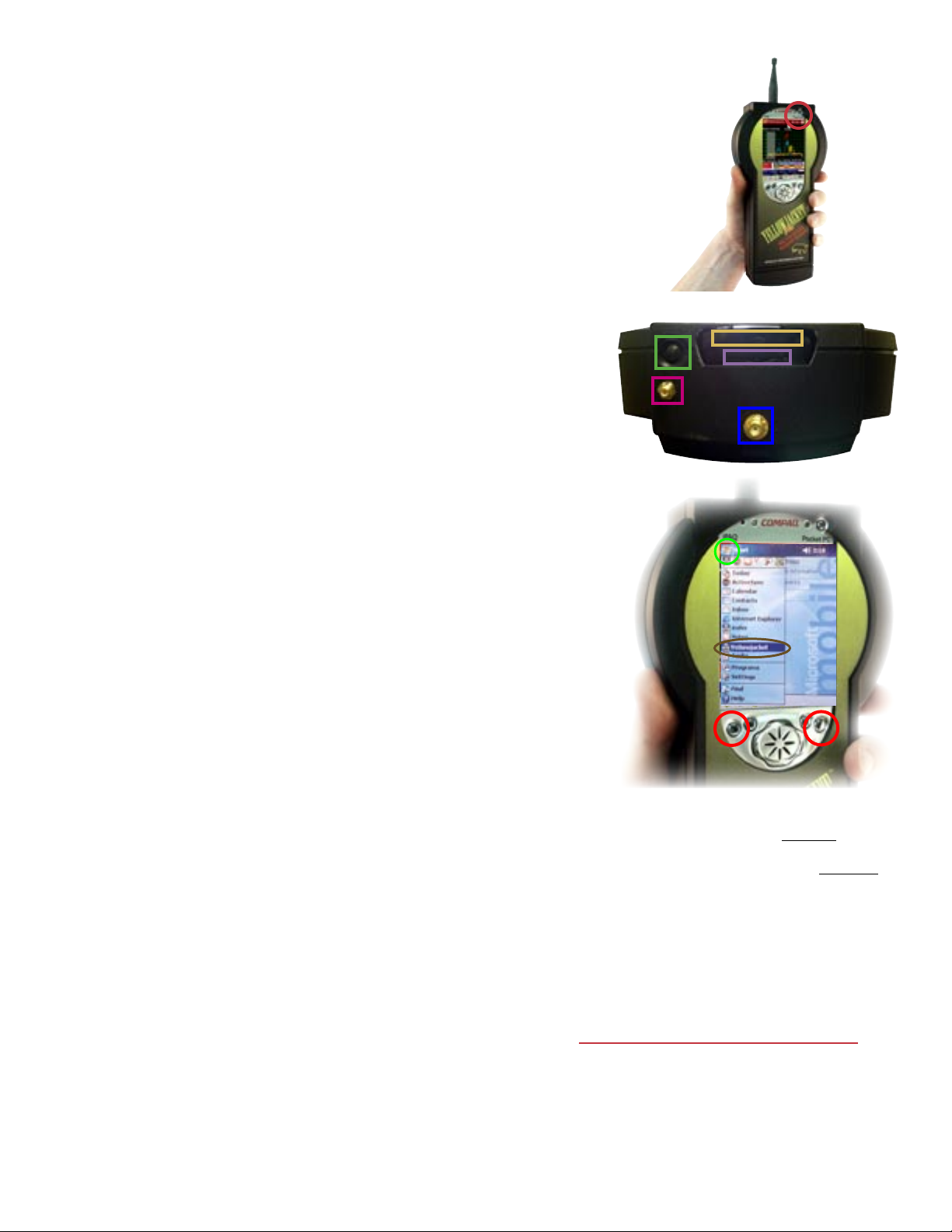
The top angle shows the removable antenna connection, sty-
lus, GPS antenna connection (optional), IrDA port and SD card
slot. Always keep the IrDA port clean and clear of obstacles
for data transmission.
STARTING UP YellowjacketPLUS
Power up your YellowjacketPLUS by pushing power but-
ton in upper right corner of unit. This power will automati-
cally power up the YellowjacketPLUS receiver also. When you
power down the iPAQ, (push the power button on the upper
right quickly-holding this button will also toggle the backlight
on and off) your Yellowjacket PLUS receiver will also shut
down. Connect the included antenna to the SMA connector
and remove the stylus by pushing down on it. Use your stylus to tap onto the Windows® icon in the upper left corner.
Choose YellowjacketPLUS in the pulldown menu. Data may be
transferred to a PC via the IrDA window or USB or serial connection. Install Yellowjacketplus software by connecting your
iPAQ to your PC and inserting included BVS software CD-ROM
(red disc) into PC to begin installation.
YellowjacketPLUS ACCESSORIES
YellowjacketPLUS includes a 2.4 GHz antenna, 2 battery packs
(10 Ni-MH cells), AC/DC charger & USB/IrDA communicator
sled and carrying case.
Page 2
Your iPAQ can be reset using 2 different methods.
If Yellowjacket software loses communications with
Yellowjacket hardware, perform a soft reset with your
stylus by pressing the reset button behind the battery
door at the bottom of the unit. Perform a hard reset by
holding in the two outer buttons for at least 10 seconds
while performing a soft reset. Warning! Hard reset
erases all RAM data from iPAQ so be sure to backup
all data and re-install your Yellowjacket application
software after a hard reset.
WARNING FOR USERS WITH BUILT-IN WIRELESS
(you must disable your iPAQ’s Bluetooth and WLAN)
1. Press the START button on the upper left hand side
of the touch screen.
2. Click on the “iPAQ Wireless” folder.
3. Click on the “Wireless Control” program.
4. Click on “All wireless features OFF”. The icons for
Bluetooth and WLAN will have red backgrounds when
disabled.
Page 4
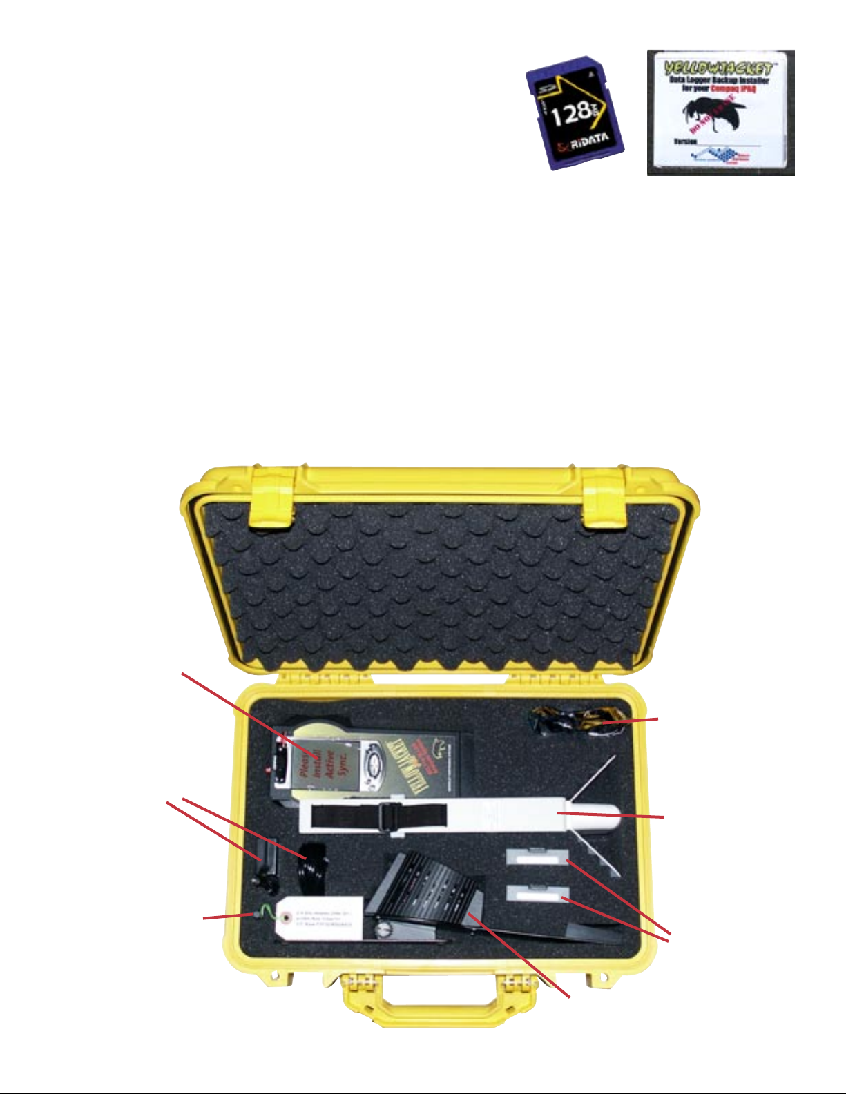
The Yellowjacket SD Backup Installer card has
been included as a courtesy. The card may be
used to log data files onto. It can also be used
on iPAQs that have never been initially set up at
the BVS factory, have had files erased or damaged in the ROM or after a hard reset has been
performed on an iPAQ. Yellowjacket software
that has been erased/lost from RAM may be
restored at anytime by accessing the “install”
file from the SD Card or Storage Card directory.
Always make sure batteries are fully charged
when doing any software installs. Yellowjacket
software that has been erased from RAM may
be restored at anytime by accessing the “reinstyj” file from the \\iPAQ File Store\\My Device
directory.
YellowjacketPLUS
with internal iPAQ
YellowjacketPLUS charger
with and power cord
2.4 GHz antenna
IrDA USB
interface
Direction Finding
Antenna (optional)
Ni-MH battery packs
iPAQ / YellowjacketPLUS
battery pack charger/cradle
Page 3
Page 5
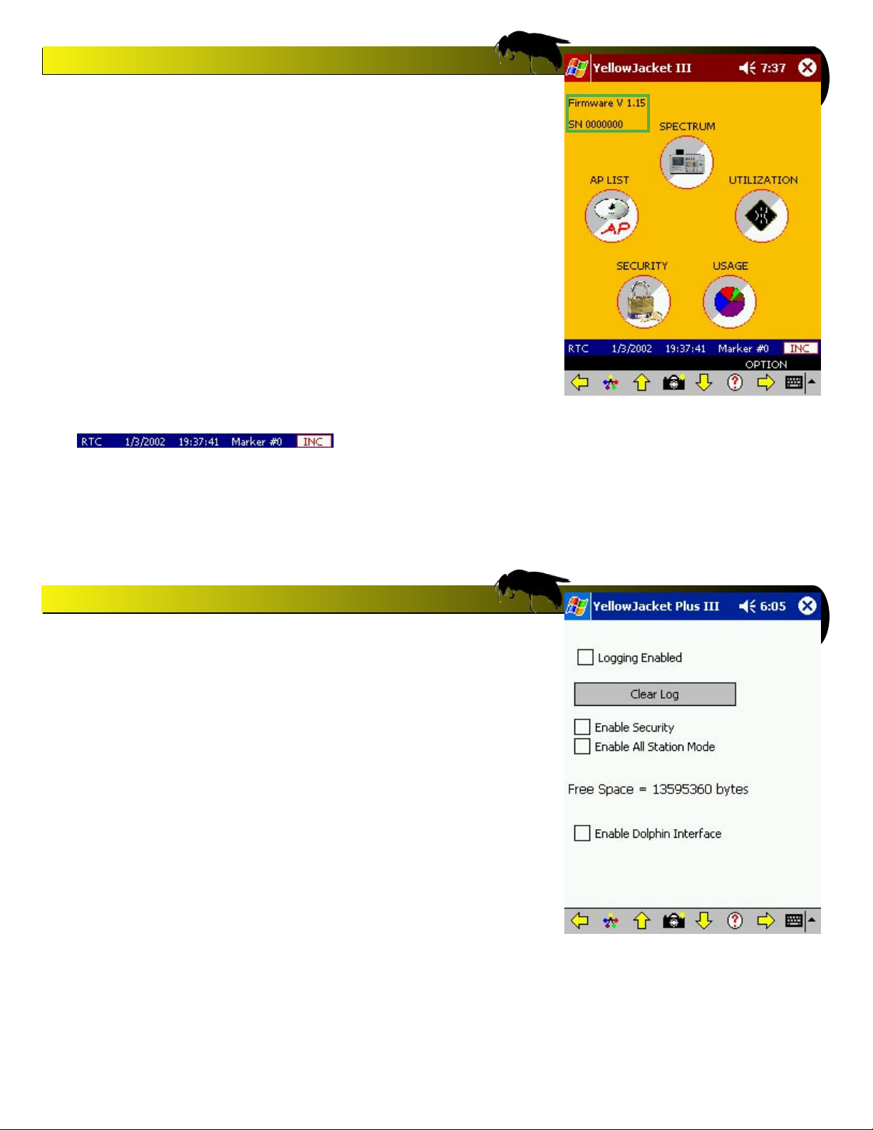
Yellowjacket Main Screen
Yellowjacket PLUS main screen allows access to all software
menus. Use the stylus or the joystick to make a selection. You
can back up and access the main screen anytime by pressing
the joystick UP, DOWN, LEFT or RIGHT (the direction is indicated at the bottom of the page.
Note that the firmware and serial number in the upper left
corner appears indicating serial connection between the iPAQ
and the Yellowjacket receiver.
RTC MARKER MODE
YellowjacketPLUS uses the internal real-time clock of the iPAQ for timing.
In addition, there is a marker that starts at 0. By pressing the button to the
right of the marker value, the marker increases by 1. These values are
stored in any log files created for later conversion by Chameleon.
Note: Users should normally see genuine
firmware and serial numbers on this screen
when Yellowjacket is functioning properly.
If your firmware and serial number appear
as 0.00 and XXXXXX, then the iPAQ software is not communicating properly with
the Yellowjacket receiver. Try troubleshooting procedures found in this user’s manual.
Yellowjacket Options Screen
Press the iPAQ’s joystick to the right when in the Main Screen
to access this options screen. Here, you may turn on logging
and clear it from memory, enable security, enable all STAtion
mode and enable Dolphin™ Mapping Interface.
Note: Logging mode will only log data from the screen (mul-
tipath, spectrum, utilization, etc.) you are currently running.
The data file containing all data collected when logging is
turned ON is called LOG.YJ3.
Note: Security mode should only be enabled after the user
has set the authorized MAC addresses in the security screen.
Otherwise, all APs detected will be seen as ‘unauthorized’ and
set off the security alarm until it is disabled.
Note: Dolphin Realtime Mapping software requires
YellowjacketPLUS’ internal GPS receiver option and a laptop
with a USB connection. Do not enable this option unless you
have the appropriet software, hardware and want to map your
802.11b study in real-time.set off the security alarm until it is
disabled.
Page 4
Page 6
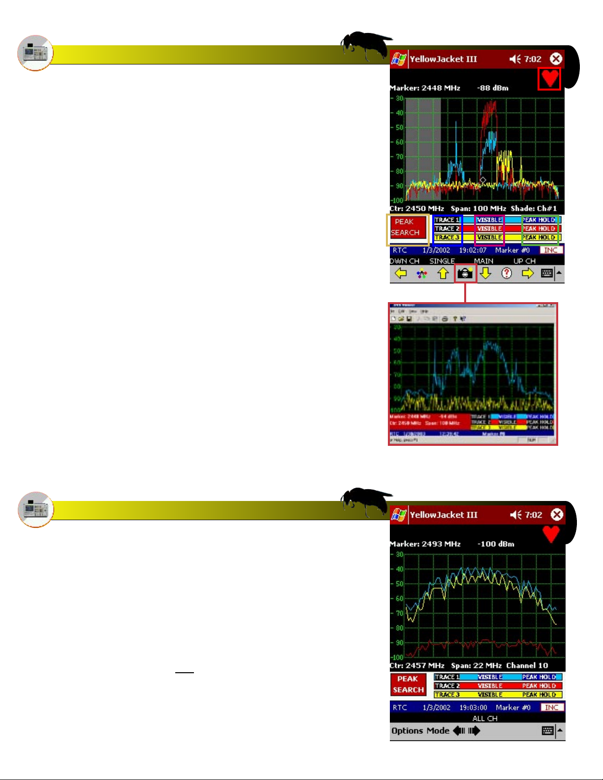
Full Spectrum Mode
The full spectrum screen has three available TRACES. These
traces can be PEAK HOLD and VISIBLE/INVISIBLE. Only one
trace can be active at any time. The buttons on the screen
below the graph change the settings on the spectrum screen.
There is also a PEAK SEARCH button that will put a diamond
on the highest point in the spectrum at that time. RSSI and
frequency information for that point will then be displayed on
top of the graph.
The BLINKING HEART on the top right indicates an active
802.11b signal. This icon also applies to the other spectrum
and multipath screens.
There is a highlight bar that allows the user to select a particular channel. This is navigated by use of the joystick and/or
arrow buttons on the menu. After highlighting a particular
channel, the user may enter into single channel spectrum
mode by pressing the UP arrow on the joystick or the UP arrow
on the menu bar.
You may take a snapshot of the full spectrum screen by pressing the CAMERA BUTTON on the menu bar. The data for the
screen will then be stored along with RTC or GPS information.
The PC Snapshot Viewer Utility will allow you to view these
snapshots on the PC and then print them out on a printer.
Single Channel Spectrum
Single channel spectrum mode works exactly like the full
spectrum mode with the exception that you are now zoomed
in to a single 802.11b channel.
NOTE: 802.11b traffic will be seen in bursts on the spectrum
screen. The energy will only rise as packets are transmitted.
You will see a constant RSSI level in the AP screens because
the RSSI measurement is synchronous with the reception of the
packet. The spectrum screen is sweeping the frequency band
because it is looking for ALL 2.4GHz energy, not just 802.11b
packets. In this way, interferers will also appear. It sweeps as
fast as it can, but if a packet is transmitted while the sweep is
at another frequency, the energy will not be seen.
Page 5
Page 7
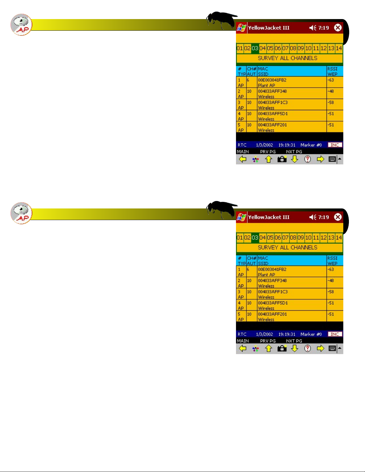
MAC AP/Station Survey Mode
Choose “AP List” mode from the main screen to get to the AP
List screen. The first screen will “survey” all 14 channels for
available AP’s. This screen will show AP’s ONLY. The single
channel mode can show all stations.
The record number, absolute channel, whether or not it is
authorized (if security is enabled), the MAC address, the SSID
(for AP’s), the RSSI, and WEP (privacy enabled bit) are shown
for each address.
Arrows will appear in the header if more than 5 AP’s are being
detected. The user can then scroll up and down to view all of
the AP/STA captured data. An address will be removed from
the list if it hasn’t been detected the next time that channel is
swept.
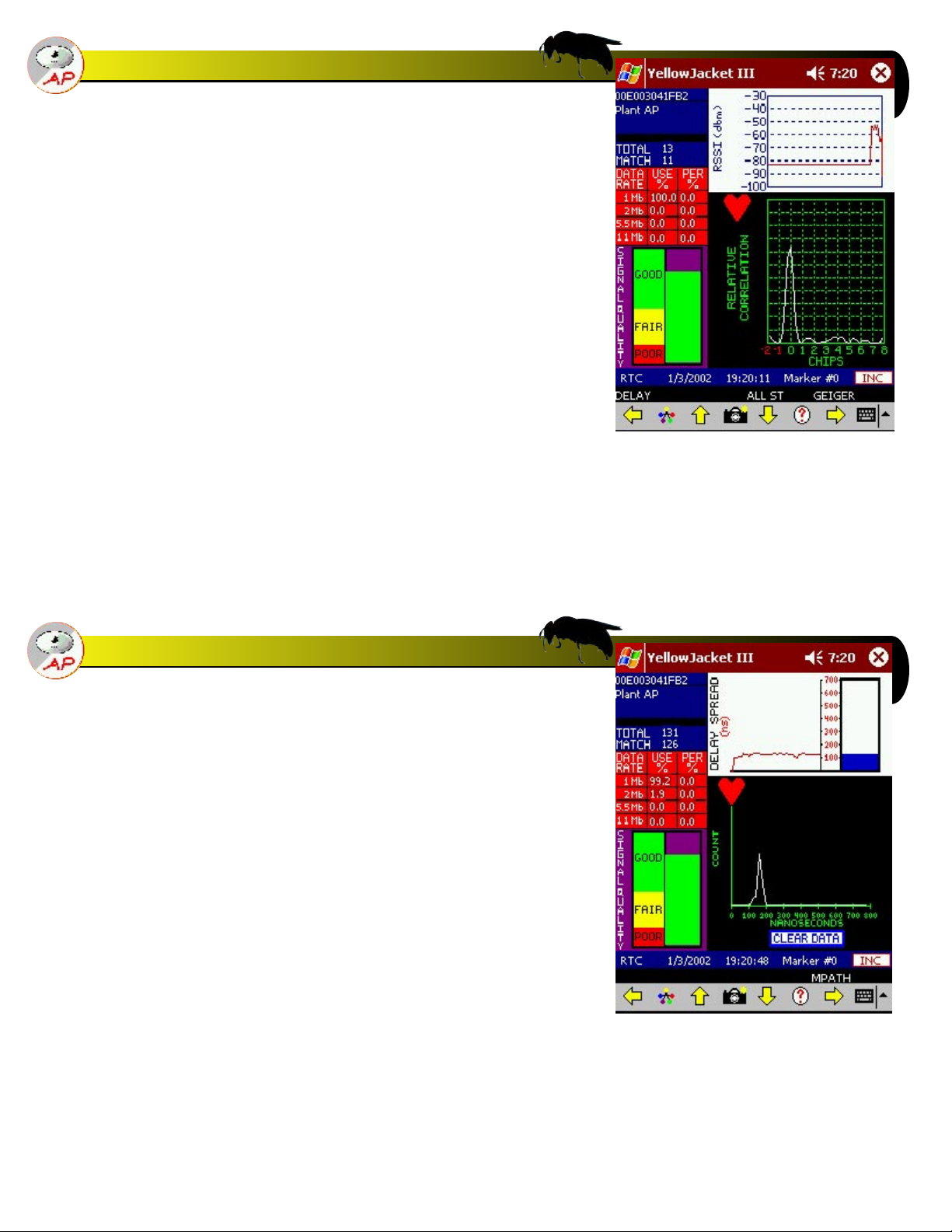
AP/Station Single Channel Mode
To see the AP’s/stations for a single channel, choose the channel by tapping the “SURVEY ALL CHANNELS” area above the
AP list. This will switch the list to APs only from one channel.
Page 6
Page 8
Multipath / Signal Quality Indicator (“Q” Factor)
The bar graph on the lower left hand side of the multipath and
the delay spread screens is known as the ‘Q’ factor graph. This
graph uses a formula to determine the quality of the direct
path and reflections of the signal by determining the ‘fatness’
of the main peak compared to the height of the direct path
component.
As the direct path gets stronger and sharper, the ‘Q’ factor
goes up. As the path gets weaker and fatter, the ‘Q’ factor
drops, signaling a possible multipath interference concern.
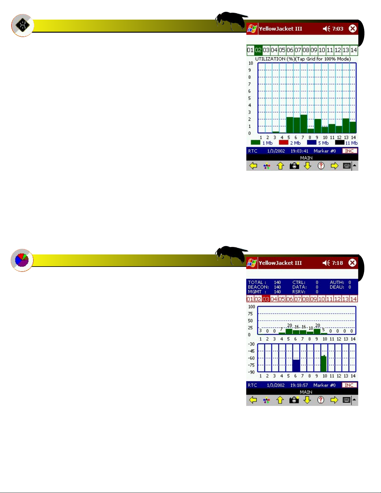
Delay Spread Screen
By moving left from the multipath screen using the joystick
and/or menu arrow, the user enters the delay spread screen.
The left of this screen shows the same information as the multipath screen. The upper right hand side of the delay spread
screen shows a running total and current delay spread in
nanoseconds.
The next graph below the running total graph is the cumulative
delay spread graph (count vs. spread). The X axis is also in
nanoseconds. The spread is cumulative and can be rest using
the provided button.
Page 7
Page 9
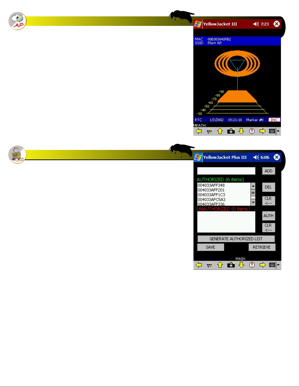
“Geiger-Counter” Mode
To find an AP/station using audible sounds as a guide, press
up on the joystick to enter the “Geiger-counter” screen. The
colors will approach white when nearing and/or pointing
directly at an AP or station. The Geiger counter sound will
also get stronger with more frequency.
Security Screen
To go to the security screen, press the security icon from the
main screen. The screen shown will appear. You may enter a
list of AP’s that are authorized (up to 1000) to be a part of the
network by entering them in the top left edit field and then
pressing the ‘ADD’ button. Press ‘DEL’ to delete an entry from
the list after highlighting that entry. Press ‘CLR<--’ to clear the
authorized list.
An authorized list can be generated from the Yellowjacketplus
by following these steps. First, go into survey mode or single
channel mode in the AP List section. Then, once all of the AP’s
have been located, go back into the security screen. Press the
‘GENERATE’ button. All of the AP’s(stations) will be transferred
into the authorized list.
When the security mode is enabled from the menu bar in the
AP/STA mode, APs and STAtions which aren’t in the authorized list will be put in the unauthorized list and a warning
message will appear.
An AP/station can be moved over to the authorized list by
pressing the ‘ADD’ button. To clear the unauthorized list, press
the ‘CLR-->’ button.
A list of AP’s can be saved and retrieved from/to the authorized
(auth.lst) and unauthorized (unauth.lst) lists by choosing the
save/retrieve options from the root directory of the Pocket
PC.
Unauthorized Warning
When YellowjacketPLUS detects any AP
that is not included in the Authorized list,
an ALERT! screen will appear and audible
warning beep will be heard. Press OK to
close the ALERT! screen. Remember that
YellowjacketPLUS will continue to sound off
the alarm each time any unauthorized AP is
detected until it is placed in the Authorized
list by the user. Check your Options Screen
(press joystick right in Main Screen) to turn
this security alert ON or OFF.
Page 8
Page 10
Utilization Screen
The utilization screen shows bandwidth utilization for every
802.11b channel. The top of the screen shows the current
channel being scanned (highlighted). The chart below shows
the utilization from 0 to 100% for channels 1 thru 14. It is color
coded to show the percentages for each data rate, as keyed on
the bottom of the screen.
The percentages add up the throughput of data at each data
rate. For instance, if there were packets at 1Mb/s containing
500,000 bits, then the corresponding percentage at 1Mb/s
would be 50%. This would be the same percentage for receiving 5.5 Mb/s on 11 Mb/s packets.
The bars stack on top of each other to reveal no more than
100%.
By tapping the grid, the display toggles between a range of
0-10% and 0-100%. This is for zooming in on low-utilization
statistics.
Usage Screen
The usage screen displays the percentage of packets being
seen by Yellowjacket PLUS in channels 1 through 14. The
graph at the bottom shows RSSI bars for APs detected and
is arranged by channel number. Note that the more APs that
occupy each channel, the thinner the vertical RSSI bars will
become (each bar represents a single AP). The PER/USAGE
calculations are now based on a rolling average over the last
number (1024) points.
Page 9
Page 11
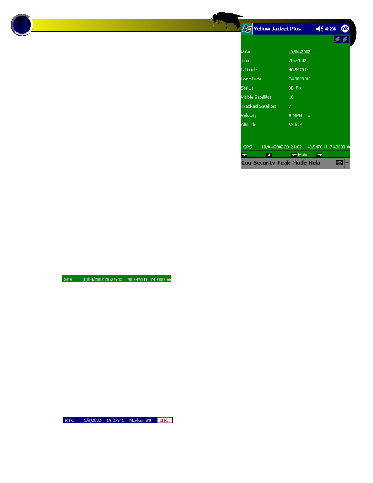
Yellowjacket PLUS GPS Option
The GPS screen of the Yellowjacket Plus provides position and
timing information from the Global Positioning System of satellites. The Motorola GPS receiver provides accurate information after synchronizing with at least 3 of the 24 satellites.
The Yellowjacket Plus must have a clear view of a good portion of the sky in order to communicate with the GPS satellites. The GPS receiver should lock within a few minutes. The
only exception is when the unit is turned on in a new area. If
the receiver was last turned on in California and now in New
Jersey, the GPS receiver could take up to an hour to lock.
The status bar at the bottom of the Yellowjacket Plus screen
shows the current date and time (Greenwich Mean) as well as
the current latitude and longitude in decimal degrees. There
is also a separate GPS screen which shows satellite information.
The GPS information is stored in the log file when enabled for
later conversion by Chameleon. Each record will be tagged
with GPS information if so desired.
If you require GPS time-stamping with your 802.11b measurements and Yellowjacket PLUS does not display the GPS screen
or the main menu screen does not show a bottom GPS data
line similar to this:
We recommend you send in your Yellowjacket PLUS to be
upgraded with the internal GPS option. See accessories page
in this manual or contact BVS for more information.
RTC MARKER MODE
If there is no GPS module attached, the YellowJacket system
uses the internal real-time clock of the iPAQ for timing. In
addition, there is a marker that starts at 0. By pressing the button to the right of the marker value, the marker increases by 1.
These values are stored in any log files created for later conversion by Chameleon. The screen above shows Yellowjacket
with an internal GPS receiver detected. The screen below
shows the RTC window when no GPS receiver is detected.
Page 10
Page 12
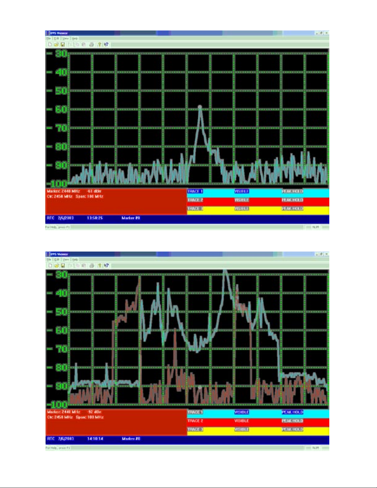
Yellowjacket Typical Spectrum Interference Examples
INTERFERENCE Narrow Band - Continuous Wave
INTERFERENCE Microwave Oven - Blue Trace - Peak Hold Red Trace - Realtime
Page 11
Page 13

INTERFERENCE - Frequency Hopper (802.11) Blue Trace - Peak Hold Red Trace - Realtime
802.11b DSSS Signal - Blue Trace - Peak Hold Red Trace - Realtime
Page 12
Page 14

INTERFERENCE-Bluetooth frequency Hopper (strong signal strength) Blue Trace - Peak Hold Red Trace - Realtime
Page 13
Page 15

Yellowjacket PLUS
Pocket PC Software Flow Chart
This screen may only
be accessed using a
YellowjacketplusPLUS with
the internal GPS receiver
option installed.
Page 14
Page 16

Troubleshooting
• Active Sync not responding - Be sure that all applicable drivers are loaded onto your PC. Drivers are included with your
IrDA USB adapter on a CD-ROM as well as drivers for Windows
2000, 98, XP and Me in a folder on the red BVS software CD
labeled “IR”.
• Cannot open Com port or System not responding – If the
Yellowjacket PLUS stops responding, try pressing OK and
restarting the application. If the Yellowjacket is still not
responding, press the small reset button located at the bottom
of your iPAQ. Do not force this reset button hard. You will see
instant results simply by pushing it gently once. See Compaq’s
usage instructions for more info on performing a hard reset.
• Yellowjacket Application Software is missing or corrupted You can find the Yellowjacket application the BVS Software CD
(red writing) included with your Yellowjacket. Re-install your
Yellowjacket software.
Users may experience COM PORT communication problems
when moving from Bird’s Eye Site Surveyor to Yellowjacket
Data Logger in Pocket PC 2002. This may be remedied by
simply pushing the reset switch on the bottom of the iPAQ.
See Bird’s Eye manual for more details.
The Yellowjacket SD Backup Installer card has been included
as a courtesy. The card may be used to log data files onto. It
can also be used on iPAQs that have never been initially set
up at the BVS factory, have had files erased or damaged in
the ROM or after a hard reset has been performed on an iPAQ.
Yellowjacket software that has been erased/lost from RAM
may be restored at anytime by accessing the “install” file
from the SD Card or Storage Card directory. Always make sure
batteries are fully charged when doing any software installs.
Yellowjacket software that has been erased from RAM may be
restored at anytime by accessing the “reinstyj” file from the
\\iPAQ File Store\\My Device directory.
Page 15
Page 17

YELLOWJACKET PLUS BATTERY CHARGING INSTRUCTIONS
Please observe the two different battery status lights. When the amber
status light on the iPAQ blinks, it is being charged and when it is on
solid, it is fully charged. When there is no status light on iPAQ, there is
no charge current. The charger status lights (label on back of charging
station) only indicate the status of the Ni-MH battery pack inserted into
the charger itself. Batteries may be charged using the charger station but
NOT ALL AT THE SAME TIME. Insert battery pack (pull tab up) into charger
only when charging the battery pack itself. A battery pack must NOT be
inserted into charger when trying to power or charge the iPAQ’s internal
battery or the YellowjacketPLUS’ internal battery pack. The included
charger may only be used to charge the included Ni-MH battery pack.
NOT Ni-CAD batteries. Batteries that are warm or hot to the touch (from
constant usage or warm ambient temperatures) will take longer to charge
than batteries of a normal temperature. Only use Ni-MH batteries with
1600 mAH or more rating. Expect over 500 cycles from each Ni-MH pack.
Below are some popular charging configurations.
Configuration 1 - charging YellowjacketPLUS removable battery pack and iPAQ internal battery
When the charger is plugged in and has
power to it, this setup will power the
Yellowjacket PLUS and simultaneously
charge the iPAQ and internal battery
pack (pack inside Yellowjacket PLUS
unit).
Ni-MH battery
pack is inserted
Configuration 2 - charging removable battery pack inside charger
When the charger is plugged in and has power to it,
this setup will only charge the battery pack inside the
charger station. The Yellowjacket PLUS will operate
in this configuration but will receive NO current for
power or charging internal battery in iPAQ or internal
battery pack (inside Yellowjacket PLUS).
Ni-MH battery
pack is inserted
Avoid this configuration as it will
charge only one battery pack (pack
inside charger) and nothing else.
Ni-MH battery
pack is inserted
Ni-MH battery
pack is inserted
X
Page 16
Page 18

TIPS
BATTERY LIFE
The Grasshopper™, Locust™, Yellow Jacket™ and Yellow Jacket Plus (fomally called Scorpion), Beetle™, Cricket™, and Cicada
W-LAN receivers use 4 or 5 Ni-MH long-lasting “AA Cells”.
1. Ni-MH batteries do not charge to full capacity the first time they are charged.
2. Ni-MH batteries do not charge to full capacity the first time they are charged after a long period of inactivity. or after a long
period of non-use.
Cause:
When charging Ni-MH batteries for the first time after long-term storage, deactivation of reactants may lead to increased battery
voltage and decreased capacity, (which causes premature termination of charging). Because batteries are chemical products
involving internal chemical reactions, performance deteriorates with prolonged storage. This is normal in Ni-MH batteries.
Resolution:
Ni-MH batteries may not charge to full capacity the first time they are charged, or after a long period of inactivity.
The first-time charge of the Ni-MH Rechargeable Battery Pack should take approximately 2 hours. If the Receiver Dock light
turns green, indicating a full charge, in less than 2 hours, repeat the charge cycle as follows:
First-time Charge:
1. To begin charging, place the instrument on the Charge Dock. Refer to your instrument’s User Guide for details.
2. When the charge light turns green, remove the W-LAN Receiver from the dock and place back on the dock after several
seconds.
3. Repeat steps 1 and 2 three or four times or until the combined charge time is 2 hours.
Subsequent charges of the W-LAN Ni-MH Battery Pack will not require multiple charging cycles unless left uncharged for a long
period of time (greater than 2 months).
NOTE: In order to prevent the Ipaq from freezing when running
YellowjacketPLUS software (therefore rendering the power button useless), make sure to:
1. ALWAYS leave the checkboxes in the SETTINGS/SYSTEM/POWER
screen unchecked. Power-save mode will lock up the application due
to the fact that the application is stopped while communicating with the
hardware..
2. Make sure that the battery level on the Ipaq remains above 40%.
The serial card interface may cease to operate when the battery level
is under 40%.
To resolve the freeze, simply press the soft reset button on the bottom of
the Ipaq with the stylus.
NEVER LEAVE THE IPAQ ON FOR EXTENDED TIMES (10 HOURS OR GREATER)
WITHOUT EXTERNAL POWER. ALWAYS SAVE ANY DATA AND THEN TURN OFF
IPAQ (TOP RIGHT POWER BUTTON) WHEN NOT IN USE. NOT DOING SO WILL
RESULT IN DAMAGE TO THE IPAQ’S INTERNAL BATTERY.
Page 17
In the PocketPC’s OS, choose Settings and then
choose System settings at the bottom. Select the
battery icon for Power Settings to access this
screen. These power settings come unchecked
from the BVS factory to ensure Yellowjacketplus
software runs optimally. Power must remain on
during logging or else data might be corrupted.
Page 19

SOFTWARE INSTALLATION
YELLOWJACKET SOFTWARE INSTALLATION FROM A SECURE DIGITAL (SD) CARD
Yellowjacket software comes pre-installed on your iPAQ, but as a courtesy, BVS includes a 128MB SD card
containing a Yellowjacket software installer should you provide your own iPAQ or lose the factory installed
files. This SD card may be used to store Yellowjacket data or other data.
Remember you must switch “lock” tab on side of SD card to “unlock” before storing or erasing any data.
To install the YellowJacket application from the SD card provided in the YellowJacket package, complete
the following steps:
1. Insert SD card into the SD slot on the top of the iPAQ.
2. Using the stylus, tap on the “Start” button on the top of the screen.
3. Tap on “Programs” near the bottom of the menu.
4. Tap on the “File Explorer” folder.
5. Make sure that the shaded area on the top of the File Explorer says “My Device”. If not, use the
upside-down triangle next to the text to choose “My Device”.
6. Tap on “SD Card”.
7. Make sure that the shaded area on the top of the File Explorer says “SD Card”. If not, use the
upside-down triangle next to the text to choose “SD Card”.
8. Choose your Yellowjacket receiver and iPAQ model for installation and tap on “install”.
9. When the message “Installation is Complete” appears, you have successfully installed the application.
The YellowJacket application will be accessible by tapping on “Start” and then “Programs”. Scroll down
to the bottom and the YellowJacket application icon will appear.
DRIVER INSTALLATION
The 24xx model iPAQ needs an updated driver for the Quatech serial card which interfaces to your BVS
product. The driver installation program can be found in the “driver” directory of your product CD. Run this
executable from your PC while the iPAQ is connected via ActiveSync. After installation, soft boot the iPAQ.
Your product should be ready to go. Symptoms of an iPAQ needing this driver include loss of communication in a high-speed data transfer mode (such as spectrum on YellowJackets and Bumble Bee).
SURVEYING
While surveying, Yellowjacket achieves the most accuracy when antenna is at a vertical 90 degree angle
and completely perpendicular to the ground or floor as shown below.
Page 18
Page 20

BVS Viewer Utility
The BVS Viewer Utility allows users of the YellowJacket series of products to display and print snapshots of full spectrum outputs. The following steps are taken to display and print a snapshot.
STEP 1: PRODUCE A SNAPSHOT
While running the YellowJacket or YellowJacket Plus, enter into the fullband spectrum screen. This is the spectrum screen
which sweeps the entire band of the receiver.
When the desired output is seen on the display, press the camera icon in the menu on the bottom of the screen. Note the
filename of the snapshot that is saved. (For example, a message box would appear that would state that the file was saved as
YJ######.YJS.
This file contains data that will be used to recreate the screen in the Viewer.
STEP 2: COPY FILE TO HOST PC
Using ActiveSync, copy the saved data file over to the PC. The file will be in the root directory of the Ipaq.
STEP 3: RUN VIEWER UTILITY
Run the BVS Viewer Utility on the PC. Open the file that was copied from the Ipaq by using FILE/OPEN. You will now view the
recreated snapshot.
STEP 4: PRINT OUT THE PICTURE
Use FILE/PRINT to print out a black and white copy of the screenshot on your printer.
Page 19
Page 21

BVS CHAMELEON DATA CONVERSION UTILTTY
Introduction
The Chameleon application software is the universal data conversion and filtering tool for BVS
Receivers.
The Chameleon was designed to greatly simplify the transfer of receiver data to many popular post-processing applications such as MapInfo and MS Excel.
The following sections of this document outline the various features of the Chameleon WLAN software.
Installation
Installation of Chameleon is straightforward. Use the enclosed CD and follow the instructions.
Starting the Application
Start Chameleon by clicking on the icon created by the installation utility. The main screen will show up.
All steps for the conversion of data are taken from this screen.
Chameleon WLAN Main Screen
Input File
The first step is the choosing of files for input and output. Choose the data file that is to be converted. The
Chameleon will automatically determine which product created the file. Chameleon will display the product on the top of the screen. Then choose the name of the file to store the conversion results. By default,
the filename for input will be chosen with a “.out” extension.
Page 20
Page 22

Output Format
By selecting the appropriate post-processing application, the correct fields will be selected and placed in
the field selection screen in the appropriate order. The user may also choose “none”. Whether or not the
field titles are in the output can be selected.
Also, the delimiting character of the fields in the output file is chosen in this section.
Output Field Selection
This section enables the selection of those fields that are to be placed in the output file. The individual
fields for the data types will appear in the far right box when the data type is selected in the “selected”
box.
Conversion
The final step in the step-by-step process is the “conversion” section. Press the CONVERT button. The
progress bar will be updated as the file is being processed. The speed of conversion will vary based on
the size of the data file.
Page 21
Page 23

YELLOW JACKET PLUS OPERATION WITH DOLPHIN™ SOFTWARE
In order to get your YellowJacket Plus to interface with Dolphin real-time software, you
must perform the following steps in the correct order:
1. Start Dolphin software and create a geoset with your maps as outlined in the Dolphin
manual. Enter the registration code for your hardware in the tools menu as outlined in
the Dolphin registration letter in your package.
2. Make sure your YellowJacket Plus is locked into the charging cradle, the infrared
device is connected to the USB port, and that the system tray on the host PC shows
another infrared device is present.
3. Start your YellowJacket Portal software.
4. Start the YellowJacket Plus software on the YellowJacket Plus Ipaq device.
5. Go to the options menu in Yellowjacket and place a checkmark for ‘Dolphin interface’.
6. Go back to the main menu and then enter the AP List screen.
You should now see GPS information on the YellowJacket Data Logger and on Dolphin.
Page 22
Page 24

BVS Dolphin Real-Time Mapping Tool
User Manual
Minimum System Requirements
Pentium II
500 MHz
64MB RAM
100MB free on Hard Drive
Operating System: Windows 95, 98, ME, 2000
BVS GPS receiver interface: 1 free serial port:
INTRODUCTION
The Dolphin real-time mapping tool is used as a companion to a BVS Receiver with GPS. This tool is used
to display scanned points on a map at the location(s) scanned. The tool receives data from a BVS data
logger that communicates with the BVS receiver.
FIGURE 1 – BVS DOLPHIN
OVERVIEW
The Dolphin software receives data from the data logger for the individual product (see Figure 2). For
example, if the Fox is the product, it would talk to the Fox Data Logger running on the PC. At the same
time, the Dolphin software would also be running on the PC.
Page 23
Page 25

FIGURE 2 – DOLPHIN DATA FLOW
The Fox Data Logger would send data in a Windows message that includes information wished to be stored
on the map as well as the GPS coordinates last stored by the data logger from the unit.
The information received would then be displayed on the Dolphin screen in the form of a colored circle. If
text were also passed, it would be displayed next to the circle. The color of the circle represents the level
of the data value (usually RSSI).
This process continues until the data logger or the receiver is terminated.
QUICK START
The following steps will guide you through setup and use of the Dolphin tool.
1. Make sure you have the product (e.g. Fox) connected to a serial port or USB port and turned on.
2. Make sure the GPS antenna is attached and GPS mode is enabled.
3. Start the Dolphin software. When using the Dolphin for the first time with this product, you must enter
the registration code in order to receive data. See ‘REGISTRATION’ below.
4. Open an existing geoset or create a new geoset. See ‘CREATING A GEOSET’ or ‘OPENING A GEOSET’.
5. Add layers to your geoset corresponding to the appropriate maps of the area that you are surveying.
6. Start the data logger for the product. Make sure any necessary steps to enable Dolphin connectivity
from the data logger have been taken. Some products don’t require any steps but others have an option to
check for Dolphin connectivity.
7. You should now see data populating the maps. Some products output data at different rates. Some
802.11b products only produce data when a new AP is found.
REGISTRATION
When using Dolphin with a product for the first time, the product must be registered with Dolphin. There
is a registration letter that ships with Dolphin that shows the registration code to use to work with the
Page 24
Page 26

product purchased. This code is matched against the serial number of the unit for verification. Use the
TOOLS/PRODUCT REGISTRATION menu option to enter the correct code. This only needs to be done once
and is stored in a file for recall on future uses.
DISPLAY FIELDS
Certain fields are displayed as data records come into the Dolphin system. These fields are (from left to
right):
Longitude (in decimal degrees)
Latitude (in decimal degrees)
Data Value (usually RSSI in dBm)
Product Serial Number
Point Count (current count of points plotted on the map)
These always reflect the last data record to come into the Dolphin system.
CREATING/OPENING A GEOSET
When starting up the Dolphin system, a Geoset must be open in order for the data points coming in to be
properly attached to map layers. You can open an existing geoset or create a new geoset.
An existing geoset will have the map layers already set up. When creating a new geoset, the layer dialog
will appear. Choose layers from the maps that were purchased for use with the Dolphin. There will already
be a ‘DOLPHIN’ layer. DO NOT REMOVE this layer. This is needed to store the data points.
After choosing the map layers, the geoset is now ready to accept points.
NOTE: The maps may not be visible until the first data point comes in to center the coordinates.
SAVING A GEOSET
Pressing the toolbar button that looks like a spinning CD allows you to save the geoset loaded. Save it to
any filename for use in later Dolphin sessions.
NOTE: Data points will not be saved. Only the map layers.
CLEARING DATA POINTS
If you wish to clear the existing data from the geoset at any time, use the toolbar button that appears to be
an eraser wiping off data. The next point taken in will be considered the first point again.
PRINTING A MAP
You may print out a copy of the map by pressing the printer icon on the toolbar.
ZOOM MODE
You may zoom in or out on the map by selecting the magnifying glass icon with a ‘+’ sign for zooming in
or a ‘-‘ sign for zooming out. This will turn the cursor into the appropriate magnifying glass. Simply click
on the area to zoom in/out on and the map will adjust accordingly.
SAVE AS BITMAP
The map may be exported to a bitmap format by selecting the icon on the toolbar with a globe on the top
and the word ‘BITMAP’ on the bottom.
Page 25
Page 27

LAYER DIALOG
The layer dialog is used to add or remove layers from the geoset. Layers can include landmarks, streets,
water, etc. Choose the layers for the appropriate driving area from the maps that were purchased for use
with the Dolphin.
RECENTERING FREQUENCY
The re-centering frequency icon looks like four arrows heading in from a square on the toolbar. This lets
you choose how often you would like the map re-centered on the current point.
Depending on the rate of data coming into the Dolphin, the re-centering of the map may start to slow down
the system and/or cause flicker. This option allows you to limit the number of times the screen is recentered.
Dolphin / Yellowjacket PLUS Signal Strength Legend
Page 26
Page 28

Networking Basics
Packets and traffic
Information travels across a network in chunks called “packets.” Each packet has a header that tells where
the packet is from and where it’s going, similar to what you write on the envelope when you send a letter.
The flow of all these packets on the network is called “traffic.”
Hardware addresses
Your PC “listens” to all of the traffic on its local network and selects the packets that belong to it by checking for its hardware address in the packet header or MAC (Media Access Control). Every hardware product
used for networking is required to have a unique hardware address permanently embedded in it.
IP addresses
Since the Internet is a network of networks (connecting millions of computers), hardware addresses alone
are not enough to deliver information on the Internet. It would be impossible for your computer to find its
packets in all the world’s network traffic, and impossible for the Internet to move all traffic to every network, your PC also has an IP (Internet Protocol) address that defines exactly where and in what network
it’s located. IP addresses ensure that your local Ethernet network only
receives the traffic intended for it. Like the hierarchical system used to define zip codes, street names,
and street numbers, IP addresses are created according to a set of rules, and their assignment is carefully
administered.
Put another way, the hardware address is like your name; it uniquely and permanently identifies you. But it
doesn’t offer any clues about your location, so it’s only helpful in a local setting. An IP address is like your
street address, which contains the information that helps letters and packages find your house.
Rules for Sending Information (Protocols)
A protocol is a set of rules that define how communication takes place. For instance, a networking protocol may define how information is formatted and addressed, just as there’s a standard way to address an
envelope when you send a letter.
Networking Devices:
Bridges
A bridge joins two networks at the hardware level. This means that as far as other protocols are concerned,
the two networks are the same.
Routers
A router connects two IP networks. In contrast to a bridge, which joins networks at the hardware level, a
router directs network IP traffic based on information stored in its routing tables. A routing table matches
IP addresses with hardware addresses. The router stamps each incoming IP packet with the hardware
address that corresponds to that IP address. As a result, the packet can be picked up by the right computer
on the hardware network.
DNS (Domain Name Server)
Networks (domains) on the Internet have names that correspond to their IP addresses. A Domain Name
Server maintains a list of domain names and their corresponding addresses. This is why you can go to
Berkeley’s Web site by entering www.bvsystems.com, instead of the IP address.
Networking Terms:
Page 27
Page 29

TCP/IP (Transport Control Protocol/Internet Protocol)
TCP/IP is a collection of protocols that underlies almost every form of communication on the Internet.
DHCP (Dynamic Host Control Protocol)
DHCP is a method of automatically assigning IP addresses. Instead of assigning addresses to individual
users, addresses are assigned by the DHCP server when clients need them. This means that instead of
entering several fields of long addresses, users need only to select DHCP as their configuration method
for IP networking.
PPP (Point-to-Point Protocol)
PPP is the most common protocol for providing IP services over a modem.
NAT (Network Address Translation)
NAT is used to share one IP address among several computers. A device set up as a NAT router uses a collection of “private” IP addresses (in the range 10.0.1.2 to 10.0.1.254 for example) to allow several computers to access the Internet using one “public” IP address. When a computer using a private IP address
requests information from the Internet, the NAT router keeps a record of the computer making the request,
and sends the information to the Internet using its own IP address. When the response comes back from
the Internet, the NAT router forwards the packet to the appropriate computer.
Channel Frequency North Europe Spain France Japan
Number GHz America MKK
1 2.412 X X
2 2.417 X X
3 2.422 X X
4 2.427 X X
5 2.432 X X
6 2.437 X X
7 2.442 X X
8 2.447 X X
9 2.452 X X
10 2.457 X X X X
11 2.462 X X X X
12 2.467 X X
13 2.472 X X
14 2.483 X
DSSS INTERNATIONAL CHANNEL CHART
Page 27
Page 30

Accessories for your
YELLOWJACKET
PLUS
2.4 GHz Antenna
SMA connector
P/N SMA-001
$ 25.00
GPS Antenna
GPS magmount active antenna
with SMC male connector
P/N GPS-SMC
$ 45.00
GPS Receiver
Internal 12-channel
GPS receiver
(BVS factory installed)
P/N YJP-GPS
$ 1000.00
Rugged Carrying Case
ABS Plastic
P/N P-CASE
$ 100.00
Direction Finding Antenna
with mounting bracket,
cable & type N SMA male
9 dBi gain
P/N DFA-001
$ 250.00
Ni-MH Battery Charger with
switching transformer
P/N NIMH-000
$ 105.00
Ni-MH Battery Pack
5 AA 7.5 V
P/N NIMH-005
$ 45.00
Dolphin Realtime GPS
Mapping Software
P/N 0038-DOLP
$ Call for Pricing
IrDA USB Adapter
wireless data transfer Adaptor
P/N IRDA-000
$ 125.00
Hive™ Indoor Mapping Software
P/N 0075-BE
$ Call for Pricing
DC PowerCable Pack
Cigarette Lighter Adaptor
P/N 002NIMH
$ 50.00
Page 28
Page 31

TM
Hive
Yellowjacket Indoor 802.11 Wi-Fi Mapping Software
Create your floorplan:
Site Initiator
1
Create floorplan layouts using bitmaps on any PC
Add rooms, floors, walls, and other clutter
Import existing floorplans for modification and surveys
Survey floorplans
on a PocketPC.
Create and organize survey maps
on a PC.
Hive™ is powerful mapping software that works with
Berkeley’s Yellowjacket 802.11 (B, A or B/G) Wi-Fi receiver
system. Hive™ runs on iPAQ® Pocket PC® allowing site
surveys to be performed completely INDOORS and outdoors
using real-time mapping coverage technology. No GPS reception needed. Simply walk through an office space, warehouse
or multi-floor building - any interior space that needs to be
surveyed - and take Access Point measurements. Next, place
those measurements on top of any structural floorplan to get
a comprehensive, bird’s eye view of any WLAN based upon
MAC addresses, RSSI, SSID and more. Export AutoCAD files
into Hive™ powerful floorplan Site Initiator and scale your
rooms and walls for measurement overlays. All measurements can be transferred, stored, displayed and printed using
any PC running Windows 98, 2000, ME or XP OS.
Organize and plot your coverage:
3
Site Investigator:
Plot coverage by AP or AP groups
Save and print color plots of survey layout and collected data
802.11b
Propagation data can be studied after or during any 802.11 survey
802.11a
802.11g
Take your AP measurements:
2
Touch-screen measurement points using PocketPC®
Customizable surveys based on MAC, RSSI, SSID
Export floorplans from AutoCAD® or any bitmap
Windows CE, PocketPC and HP iPAQ are registered ® trademarks of the Microsoft Corporation and Hewlett Packard Corporation respectively.
Site Supervisor
Call us today for more information on Hive software:
(732) 548-3737 / Fax: (732) 548-3404
Internet: www.bvsystems.com
E-mail: info@bvsystems.com
wireless products
BERKELEY
VARITRONICS
SYSTEMS
Page 32

Glossary of Acronyms
AC Alternating Current
A/D Analog to Digital converter
AGC Automatic Gain Control
AP Access Point
Applet a small Application
BER Bit Error Rate
BPSK Binary Phase Shift Keying
BSS Basic Service Set
BW Band Width
CDMA Code Division Multiple Access (spread spectrum modulation)
DC Direct Current
D/A Digital to Analog
dB decibel
dBm decibels referenced to 1 milliwatt
DOS Digital Operating System
DSP Digital Signal Processing
DSSS Direct Sequence Spread Spectrum
ESS Extended Service Set
FHSS Frequency-Hopping Spread Spectrum
FIR Finite Impulse Response
GHz GigaHertz
IF Intermediate Frequency
I and Q In phase and Quadrature
IBBS Independent Basic Service Set
IrDA Infrared Data Association
kHz kiloHertz
LCD Liquid Crystal Display
LO Local Oscillator
MAC Medium Access Control
Mbits Megabits
MHz MegaHertz
NIC Network Interface Card
OFDM Orthogonal Frequency Domain Multiplexing (802.11a)
PC Personal Computer
PCS Personal Communications Service (1.8 to 2.1 GHz frequency band)
PER Packet Error Rate
PN Pseudo Noise
QPSK Quaternary Phase Shift Keying, 4-level PSK
RF Radio Frequency
RSSI Receiver Signal Strength Indicator
SSID Service Set IDentification
STA STAtion (generally a laptop client WLAN card)
UCT Universal Coordinated Time
VAC Volts Alternating Current
VGA Video graphic
WEP Wired Equivalent Protocol
WLAN Wireless Local Area Network
Page 33

IMPORTANT SAFETY INSTRUCTIONS
When using your telephone equipment, basic safety precautions should always be followed to reduce the risk of fire, electric
shock and injury to persons, including the following:
1)Read and understand all instructions.
2)Follow all warnings and instructions marked on the product.
3)Unplug this product from the wall outlet before cleaning. Do not use liquid cleaners or aerosol cleaners. Use a damp cloth
for cleaning.
4)Do not use this product near water, for example, near a bath tub, wash bowl, kitchen sink, or laundry tub, in a wet basement,
or near a swimming pool.
5)Do not place this product on an unstable cart, stand, or table. The product may fall, causing serious damage to the product.
6)Slots and openings in the cabinet and the back or bottom are provided for ventilation, to protect it from overheating these
openings must not be blocked or covered The openings should never be blocked by placing the product on the bed, sofa, rug or
other similar surface. This product should never be placed near or over a radiator or heat register. This product should not be
placed in a built-in installation unless proper ventilation is provided.
7) This product should be operated only from the type of power source indicated on the appliance. If you are not sure of the type
of power supply to your home, consult your dealer or local power company.
8)Do not allow anything to rest on the power cord. Do not locate this product where the cord will be abused by persons walking
on it.
9)Do not overload wall outlets and extension cords as this can result in the risk of fire or electric shock.
10)Never push objects of any kind into this product through cabinet slots as they may touch dangerous voltage points or short
out parts that could result in a risk of fire or electric shock. Never spill liquid of any kind on the product.
11) To reduce the risk of electric shock, do not disassemble this product, but take it to a qualified service faciI4 when some
service or repair work is required. Opening or removing covers may expose you to dangerous voltages or other risks. Incorrect
reassembly can cause electric shock when the appliance is subsequently used.
12)Unplug this product from the wall outlet and refer servicing to qualified service personnel under the following conditions:
A) When the power supply cord or plug is damaged or frayed. B) If liquid has been spilled into the product.
C)If the product has been exposed to rain or water.
D) If the product does not operate normally by following the operating instructions. Adjust only those controls, that are
covered by the operating instructions because improper adjustment of other controls may result in damage and will often require
extensive work by a qualified technician to restore the product to normal operation.
E) If the product has been dropped or the cabinet has been damaged. F) If the product exhibits a distinct change in performance.
13)Avoid using the product during an electrical storm. There may be a remote risk of electric shock from lightning.
14)Do not use the telephone to report a gas leak in the vicinity of the leak.
INSTALLATION INSTRUCTIONS
1. Never install telephone wiring during a lightning storm.
Page 34

2. Never install telephone jacks in wet locations unless the jack is specifically designed for wet locations.
3. Never touch uninsulated telephone wires or terminals unless the telephone line has been disconnected at the network interface.
4. Use caution when installing or modifying telephone lines.
INSTRUCTION FOR BATTERIES
CAUTION: To Reduce the Risk of Fire or Injury to Persons, Read and Follow these Instructions:
1. Use only the type and size of batteries mentioned in owner’s manual.
2. Do not dispose of the batteries in a fire. The cells may explode. Check with local codes for possible special disposal
instructions.
3. Do not open or mutilate the batteries. Released electrolyte is corrosive and may cause damage to the eyes or skin. It
may be toxic if swallowed.
4. Exercise care in handling batteries in order not to short the battery with conducting materials such as rings, bracelets,
and keys. The battery or conductor may overheat and cause burns.
5. Do not attempt to recharge the batteries provided with or identified for use with this product. The batteries may leak
corrosive electrolyte or explode.
6. Do not attempt to rejuvenate the batteries provided with or identified for use with this product by heating them. Sudden
release of the battery electrolyte may occur causing burns or irritation to eyes or skin.
7. When replacing batteries, all batteries should be replaced at the same time. Mixing fresh and discharged batteries
could increase internal cell pressure and rupture the discharged batteries. (Applies to products employing more than one separately replaceable primary battery.)
8. When inserting batteries into this product, the proper polarity or direction must be observed. Reverse insertion of batteries can cause charging, and that may result in leakage or explosion. (Applies to product employing more than one separately
replaceable primary battery.)
9. Remove the batteries from this product if the product will not be used for a long period of time (several months or more)
since during this time the battery could leak in the product.
10. Discard “dead” batteries as soon as possible since “dead” batteries are more likely to leak in a product.
11. Do not store this product, or the batteries provided with or identified for use with this product, in high-temperature
areas. Batteries that are stored in a freezer or refrigerator for the purpose of extending shelf life should be protected from condensation during storage and defrosting. Batteries should be stabilized at room temperature prior to use after cold storage.
Page 35

2.4 GHz Direction Finding
Corner Reflector
2.4 GHz Omni-Directional (7.5” long)
Page 36

TM
YELLOWJACKET
PLUS
802.11b Wi-Fi Analysis System
GPS
ready
Yellowjacket™ PLUS is a wireless
receiver system designed specifi-
cally for sweeping, analyzing and
optimizing 2.4 GHz Wireless Local
Area Networks. The instrument
measures coverage of DSSS networks which operate on the IEEE
802.11b standard allowing the
user to determine the AP (Access
Point), PER (Packet Error Rate),
Multipath (Ec/Io) and RSSI signal
levels aiding in locating the hub
and access points of neighbor-
ing WLANs. Yellowjacket™ PLUS
functions as a complete WLAN
analysis system housing both the
PocketPC® Windows CE® environment along with Berkeley’s precision
receiver technology.
Optional Direction Finding Antenna allows YELLOWJACKET PLUS users to pinpoint any AP or Client Card.
FEATURES:
• Measure 2.4 GHz coverage for direct sequence (DSSS) WLANs
(IF wideband 22 MHz) within the IEEE 802.11b standard
• Receive, filter and process DSSS studies all in Pocket PC®
• 64K color backlit display for real-time color-coded signal analysis
• Touch screen, Windows® PDA-like interface using a stylus pen
• Integrated HP IPAQ® PocketPC®
• Measures Packet Error Rate; data rate percentage breakdowns
Multipath and RSSI; narrow band & total channel power
• Complex Access Point / Station list analysis including WEP, RSSI,
Multipath, PER, Absolute Channel, Survey Sweep and SSID
• Optional internal 12-channel GPS receiver available
• Optional Dolphin™ Real-time GPS mapping software available
• Removable battery pack (5 AA Ni-MH cells) and also can be
powered from 12VDC car cigarette lighter
Measurements:
MAC
SSID
PER (1,2,5.5,11Mbit)
Total Channel Power
Narrowband RSSI
Multipath in Chips
Multipath in nsec.
WEP
Survey Sweep
Absolute Channel
LAT/LONG/ALT/UTC via GPS
Call us today for more information:
(732) 548-3737 / Fax: (732) 548-3404
Internet: www.bvsystems.com
E-mail: info@bvsystems.com
Windows CE, PocketPC and HP iPAQ are registered ® trademarks of the Microsoft Corporation and Hewlett Packard Corporation respectively.
wireless products
BERKELEY
VARITRONICS
SYSTEMS
Page 37

TM
YELLOWJACKET
PLUS
802.11b Wi-Fi Analysis System
BANDS SUPPORTED ISM: 2.400-2.495 GHz
RF SENSITIVITY (Wide Band) -20 to -90 dBm
RSSI MEASUREMENT (Narrow Band -30 to -90 dBm @ 343.75 kHz resolution bandwidth
TUNING INCREMENTS Tunes 11 USA channels & 3 international channels
PACKET PREAMBLE DEMODULATOR and ANALYZER:
Multipath Measurement and Graphical Display
CORRELATED POWER MEASUREMENTS: RATIO
Correlated Power (dBm) -30 dBm : -100 dBm
Correlated Power to Total Power Ec/Io (dB) 0 dB : -10 dB
Total Channel Power Measurement -20 dBm : -90 dBm
GENERAL SPECIFICATIONS
IF Bandwidth: Wideband 22 MHz
Stability: + 2.5 PPM Temp range 32° to 120 F°
Antenna: SMA Female 50 ohm
Controls: touch-screen Windows CE® environment
Warm Up Time: < 3 minutes
Power: Internal battery pack (5 AA Ni-MH batteries)
Weight: 3 lbs.
Dimensions: 2” H x 4” W x 9” L (water resistant, high impact ABS plastic case)
When coupled with optional internal GPS receiver and
Dolphin™ mapping software, Yellowjacket PLUS™
becomes a powerful, real-time 802.11 W-LAN
mapping coverage tool for WISPs, Wardriving
and Wi-Fi analysis. Perform drive-studies on
campus, locate hacklers and time stamp sources
of interference all in REALTIME all in
YellowjacketPLUS™.
Yellowjacket PLUS™ includes a rugged
travel case, 2.4 GHz antenna, two NiMH battery packs, charger base, IrDA
USB communicator link and optional
Direction Finding Antenna.
YELLOWJACKET FEATURES:
SPECTRUM MODE:
Full spectrum (14 channel) sweep
Single channel zoom
Peak Search and Hold
3 distinct waveform signal traces
AP ANALYSIS:
Survey sweep of channels for all APs
“Q” Factor signal strength quality meter
Individual channel analysis of APs or STAs
Absolute channel
SSID
AP manufacturer’s ID
WEP detection
RSSI for each AP/STA in true dBm
Multipath in chips and nanoseconds
PER breakdown/usage for 1, 2, 5.5 and 11 Mbit/Sec.
“Geiger Mode” for direction finding individual AP/STA
NETWORK SECURITY:
Authorize or Unauthorize up to 1000 MAC addresses
Generate valid AP list automatically
Upload AP list from PC
Flag invalid APs as “suspect”
Berkeley Varitronics Systems, Liberty Corporate Park, 255 Liberty Street, Metuchen, NJ 08840
Phone 732-548-3737 • Fax 732-548-3404 • www.bvsystems.com • E-mail: info@bvsystems.com
 Loading...