

Page 1

HP ROM-Based Setup Utility
User Guide
Part Number 347563-009
May 2009 (Ninth Edition)
Page 2

© Copyright 2003, 2009 Hewlett-Packard Development Company, L.P.
The information contained herein is subject to change without notice. The only warranties for HP products and services are set forth in the express
warranty statements accompanying such products and services. Nothing herein should be construed as constituting and additional warranty. HP
shall not be liable for technical or editorial errors or omissions contained herein.
Confidential computer software. Valid license from HP required for possession, use or copying. Consistent with FAR 12.211 and 12.212,
Commercial Computer Software, Computer Software Documentation, and Technical Data for Commercial Items are licensed to the U.S.
Government under vendor's standard commercial license.
Microsoft, Windows, and Windows Server are U.S. registered trademarks of Microsoft Corporation.
Intel is a trademark or registered trademark of Intel Corporation or its subsidiaries in the United States and other countries.
Intended audience
This document is for the person who installs, administers, and troubleshoots servers and storage systems.
HP assumes you are qualified in the servicing of computer equipment and trained in recognizing hazards
in products with hazardous energy levels.
Page 3

Contents
Introduction.................................................................................................................................. 7
Overview ................................................................................................................................................. 7
Running RBSU........................................................................................................................................... 7
RBSU menu (HP ProLiant G6 servers or server blades)....................................................................... 9
RBSU menu overview................................................................................................................................. 9
System Options menu (G6 servers) ............................................................................................................10
Serial Port Options (G6 servers) ......................................................................................................10
Embedded NICs (G6 servers).......................................................................................................... 12
Advanced Memory Protection (G6 servers) ....................................................................................... 13
USB Options (G6 servers)............................................................................................................... 14
Processor Options (G6 servers) ....................................................................................................... 17
NUMLOCK Power-On State (G6 servers).......................................................................................... 24
Power Management Options (G6 servers) ..................................................................................................24
HP Power Profile (G6 servers) ......................................................................................................... 24
HP Power Regulator (G6 servers)..................................................................................................... 25
Redundant Power Supply Mode (G6 servers) ....................................................................................27
Advanced Power Management Options (G6 servers) ......................................................................... 27
PCI IRQ Settings (G6 servers).................................................................................................................... 34
PCI Device Enable/Disable (G6 servers) .................................................................................................... 34
Standard boot order (IPL) (G6 servers) ....................................................................................................... 36
Boot Controller Order (G6 servers) ............................................................................................................ 36
Date and Time (G6 servers) ...................................................................................................................... 38
Server Availability (G6 servers)................................................................................................................. 38
ASR Status (G6 servers).................................................................................................................. 39
ASR Timeout (G6 servers) ............................................................................................................... 39
Thermal Shutdown (G6 servers)....................................................................................................... 41
Wake-On LAN (G6 servers)............................................................................................................ 41
POST F1 Prompt (G6 servers).......................................................................................................... 42
Power Button (G6 servers) .............................................................................................................. 44
Automatic Power-On (G6 servers).................................................................................................... 45
Power-On Delay (G6 servers).......................................................................................................... 45
Server Security (G6 servers)...................................................................................................................... 46
Set Power-On Password (G6 servers) ............................................................................................... 47
Set Admin Password (G6 servers) .................................................................................................... 48
Trusted Platform Module (G6 servers)............................................................................................... 48
BIOS Serial Console/EMS Support (G6 servers).......................................................................................... 52
BIOS Serial Console Port (G6 servers).............................................................................................. 53
BIOS Serial Console Baud Rate (G6 servers)..................................................................................... 54
EMS Console (G6 servers)..............................................................................................................55
BIOS Interface Mode (G6 servers) ...................................................................................................56
Server Asset Text (G6 servers)................................................................................................................... 56
Set Server Info Text (G6 servers)...................................................................................................... 57
Set Administrator Info Text (G6 servers)............................................................................................ 58
Set Service Contact Text (G6 servers) ............................................................................................... 59
Custom POST Message (G6 servers) ................................................................................................60
Contents 3
Page 4

Advanced Options Menu (G6 servers) ....................................................................................................... 60
Advanced System ROM Options (G6 servers) ...................................................................................61
Video Options (G6 servers) ............................................................................................................68
Thermal Configuration (G6 servers) ................................................................................................. 68
Service Options (G6 servers)........................................................................................................... 69
Advanced Performance Tuning Options (G6 servers).......................................................................... 71
Drive Write Cache (G6 servers) ...................................................................................................... 75
Asset Tag Protection (G6 servers)..................................................................................................... 76
System Default Options (G6 servers).......................................................................................................... 77
Restore Default System Settings (G6 servers) ..................................................................................... 78
Restore Settings/Erase Boot Disk (G6 servers) ...................................................................................79
User Default Options (G6 servers).................................................................................................... 80
Utility Language (G6 servers).................................................................................................................... 81
RBSU menu (HP ProLiant G5 and earlier servers or server blades) .................................................... 82
RBSU menu overview............................................................................................................................... 82
System Options....................................................................................................................................... 83
Embedded Serial Port A ................................................................................................................. 84
Embedded Serial Port B.................................................................................................................. 84
Virtual Serial Port........................................................................................................................... 85
Optional LPT Port........................................................................................................................... 86
Optional LPT Mode Support............................................................................................................86
Integrated Diskette Controller .......................................................................................................... 86
NUMLOCK Power-On State ............................................................................................................ 86
Embedded NICs............................................................................................................................ 87
Diskette Write Control.................................................................................................................... 87
Diskette Boot Control...................................................................................................................... 87
Advanced Memory Protection .........................................................................................................87
USB Control.................................................................................................................................. 88
USB 2.0 EHCI Controller ................................................................................................................ 89
Power Regulator for ProLiant ........................................................................................................... 89
USB External Port Capability........................................................................................................... 90
Ultra Low Power State .................................................................................................................... 91
PCI Devices ............................................................................................................................................ 92
Standard Boot Order (IPL)......................................................................................................................... 93
Boot Controller Order .............................................................................................................................. 93
Date and Time ........................................................................................................................................ 94
Server Availability................................................................................................................................... 94
ASR Status.................................................................................................................................... 95
ASR Timeout ................................................................................................................................. 95
Thermal Shutdown......................................................................................................................... 95
Wake-On LAN.............................................................................................................................. 95
POST Speed Up ............................................................................................................................ 95
POST F1 Prompt............................................................................................................................ 95
Power Button................................................................................................................................. 96
Automatic Power-On...................................................................................................................... 96
Power-On Delay............................................................................................................................ 96
Server Passwords .................................................................................................................................... 96
Set Power-On Password ................................................................................................................. 97
Set Admin Password ...................................................................................................................... 97
Trusted Platform Module ................................................................................................................. 97
Network Server Mode.................................................................................................................... 99
QuickLock ....................................................................................................................................99
BIOS Serial Console/EMS Support............................................................................................................ 99
Contents 4
Page 5

BIOS Serial Console Port..............................................................................................................100
BIOS Serial Console Baud Rate..................................................................................................... 101
EMS Console .............................................................................................................................. 101
BIOS Interface Mode ...................................................................................................................102
Server Asset Text................................................................................................................................... 102
Set Server Info Text...................................................................................................................... 102
Set Administrator Info Text ............................................................................................................ 103
Set Service Contact Text ............................................................................................................... 104
Custom POST Message ................................................................................................................ 104
Advanced Options Menu .......................................................................................................................104
Multi-Processor Specification (MPS) Table Mode.............................................................................. 105
ROM Selection............................................................................................................................ 106
Restore Default System Settings...................................................................................................... 106
Restore Settings/Erase Boot Disk ................................................................................................... 106
User Default Options.................................................................................................................... 107
NMI Debug Button....................................................................................................................... 107
Virtual Install Disk ........................................................................................................................ 107
Secondary IDE Channel Support.................................................................................................... 107
BIOS Enhanced RAID................................................................................................................... 108
Node Interleaving........................................................................................................................ 108
Serial Number ............................................................................................................................108
Product ID .................................................................................................................................. 108
Drive Write Cache ...................................................................................................................... 108
SATA Software RAID.................................................................................................................... 108
Optional PCI-X Riser Fan Monitoring .............................................................................................. 108
Processor Options ....................................................................................................................... 109
Power Supply Requirements Override............................................................................................. 110
Embedded VGA Control............................................................................................................... 110
Utility Language .................................................................................................................................... 111
ROM-based enhancements ........................................................................................................ 112
ROM-based enhancements overview........................................................................................................ 112
Embedded server setup.......................................................................................................................... 112
Setup Utility ................................................................................................................................ 113
Inspect Utility .............................................................................................................................. 114
Diagnostics Utility........................................................................................................................ 114
Auto-Configuration Process..................................................................................................................... 116
Boot options ......................................................................................................................................... 117
Operating System Installation.................................................................................................................. 117
Command Line Interface ............................................................................................................ 119
Command Line Interface Overview .......................................................................................................... 119
Dual-Mode ROM-Based Utilities............................................................................................................... 119
CLI Mode Selection ............................................................................................................................... 119
Inspect CLI Commands........................................................................................................................... 120
RBSU CLI Commands............................................................................................................................. 120
System Maintenance CLI Commands........................................................................................................ 123
Command Buffering Support................................................................................................................... 123
Additional CLI support ........................................................................................................................... 123
RBSU configuration flow ............................................................................................................ 124
RBSU configuration flow overview ........................................................................................................... 124
Manual path flow.................................................................................................................................. 124
Scripted installation flow ........................................................................................................................125
Contents 5
Page 6

Configuration Replication Utility .................................................................................................... 125
Array Configuration Replication Utility ........................................................................................... 127
Acronyms and abbreviations...................................................................................................... 128
Index....................................................................................................................................... 131
Contents 6
Page 7

Introduction
Overview
HP ProLiant Generation 2 and later servers have a configuration utility embedded in the system ROM. The
configuration utility, RBSU, starts when you press the F9 key from the startup sequence.
RBSU performs a wide range of configuration activities that may include:
• Configuring system devices and installed options
• Displaying system information
• Selecting the primary boot controller
• Configuring online spare memory
IMPORTANT: Menu options may differ from those in this document, depending on specific
server options.
Based on the generation of the server blade, this user guide is divided into two sections:
• HP ProLiant G6 servers or server blades ("RBSU menu (HP ProLiant G6 servers or server blades)" on
page 9)
• HP ProLiant G5 and earlier servers or server blades (including the HP ProLiant servers and server
blades with AMD processors) ("RBSU menu (HP ProLiant G5 and earlier servers or server blades)" on
page 82)
Running RBSU
1. To run RBSU and modify configuration settings, press the F9 key when prompted during the startup
sequence.
2. Modify configuration settings as needed.
3. Exit RBSU by pressing Esc at the main menu. To confirm configuration setting changes, reboot the
system when exiting RBSU.
Introduction 7
Page 8
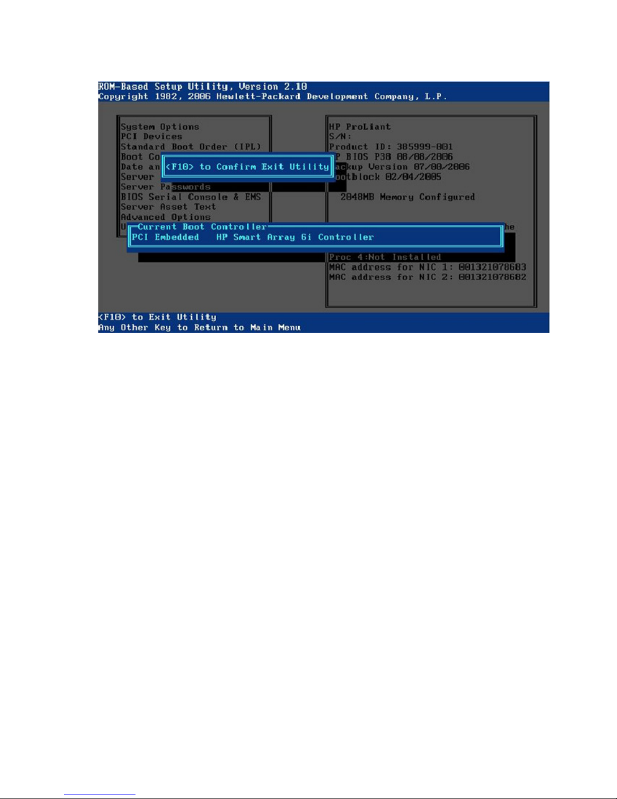
A confirmation to exit displays on the screen, and the current boot controller also displays for
reference purposes.
4. To confirm exiting RBSU, press the F10 key.
The server restarts using the new configuration settings.
Introduction 8
Page 9
RBSU menu (HP ProLiant G6 servers or server
blades)
RBSU menu overview
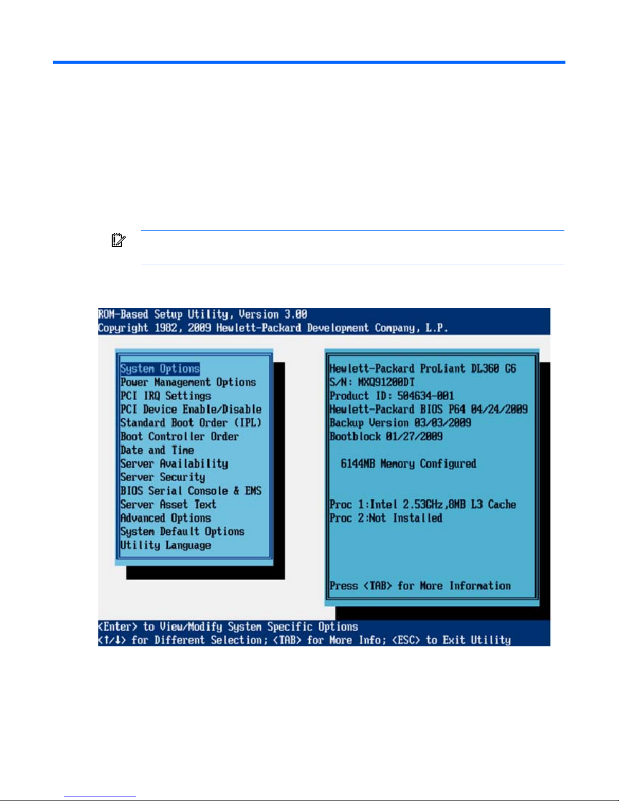
The RBSU menu lists configuration settings to view or modify.
IMPORTANT: Menu options may differ from those in this document, depending on specific
On the right-hand side of the screen, a window displays basic server information, including the server
model, serial number, BIOS version, backup BIOS version, memory installed, and processors installed.
server options.
Pressing the F1 key when any sub-menu option is highlighted enables you to view a description of that
feature. While the menus are provided in various languages, the help text is provided in English only.
RBSU menu (HP ProLiant G6 servers or server blades) 9
Page 10

If a BIOS Serial Console is active, RBSU will run in CLI mode. The following command prompt screen
appears.
The CLI mode of RBSU ("CLI Mode Selection" on page 119) is a command-prompted interface that
provides equivalent functionality to the menu-based mode.
System Options menu (G6 servers)
The System Options menu enables basic I/O server configuration with the following options:
• Serial Port Options (G6 servers) (on page 10)
• Embedded NICs (G6 servers) (on page 12)
• Advanced Memory Protection (G6 servers) (on page 13)
• USB Options (G6 servers) (on page 14)
• Processor Options (G6 servers) (on page 17)
• NUMLOCK Power-On State (G6 servers) (on page 24)
IMPORTANT: Menu options may differ from those in this document, depending on specific
Serial Port Options (G6 servers)
• Serial Port 1 (G6 servers) (on page 11)
• Virtual Serial Port (G6 servers) (on page 12)
server options.
RBSU menu (HP ProLiant G6 servers or server blades) 10
Page 11
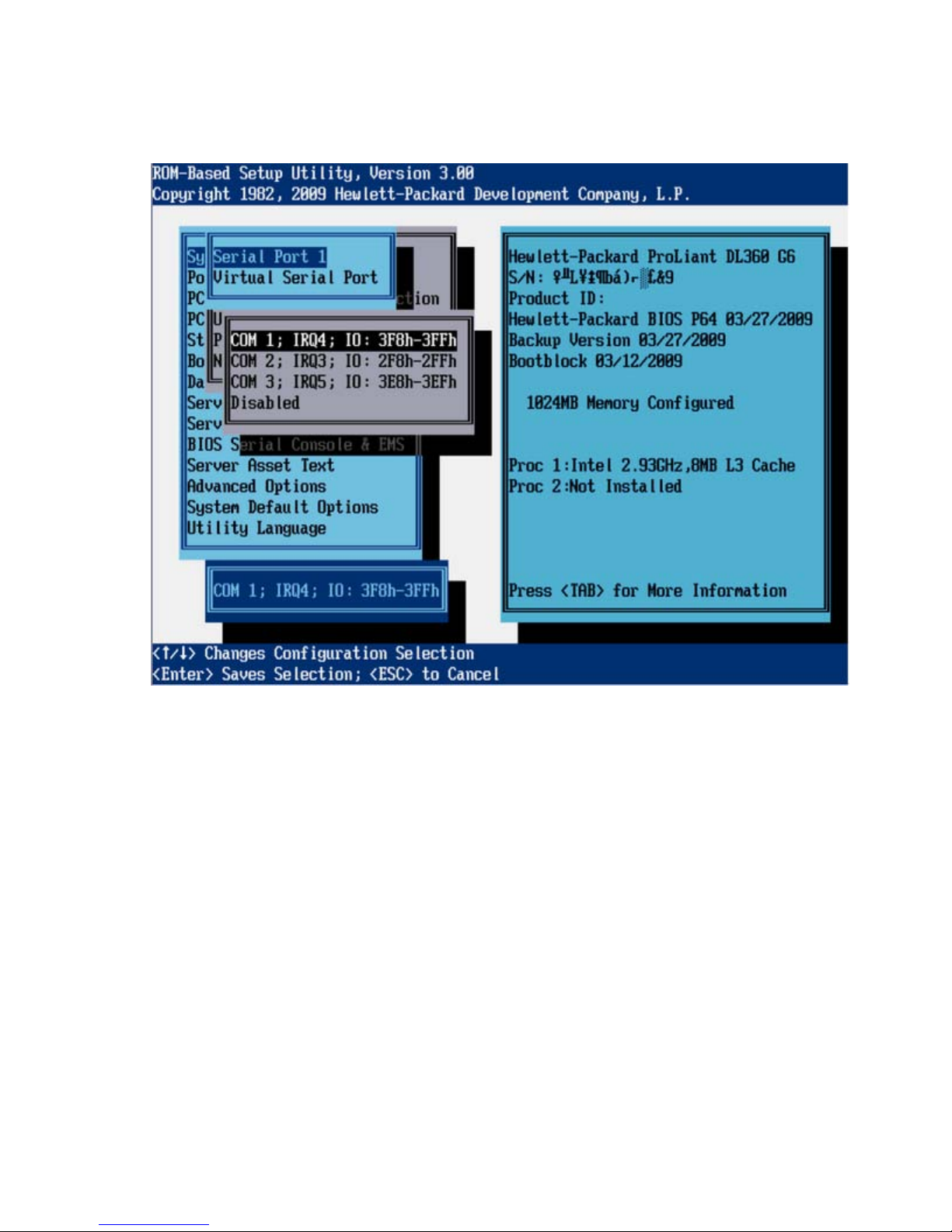
Serial Port 1 (G6 servers)
The Serial Port 1 option assigns the logical COM Port number and associated default resources to the
selected physical serial port. This setting may be overwritten by the OS.
RBSU menu (HP ProLiant G6 servers or server blades) 11
Page 12
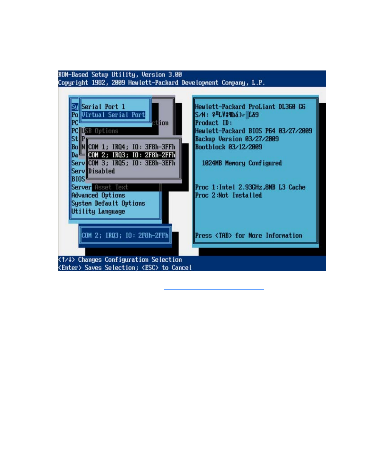
Virtual Serial Port (G6 servers)
The Virtual Serial Port option assigns the logical COM Port number and associated default resources used
by the Virtual Serial Port. The VSP enables the ILO Management Controller to appear as a physical serial
port to support the BIOS Serial Console and the OS serial console.
For detailed information about iLO configurations, refer to the HP Integrated Lights-Out User Guide on the
Documentation CD or to the HP website (http://www.hp.com/servers/lights-out
Embedded NICs (G6 servers)
The Embedded NICs option enables Network boot for embedded NICs:
• NIC 1 Boot Options
o Network Boot (default)
o Disabled
• NIC 2 Boot Options
o Network Boot
).
RBSU menu (HP ProLiant G6 servers or server blades) 12
Page 13
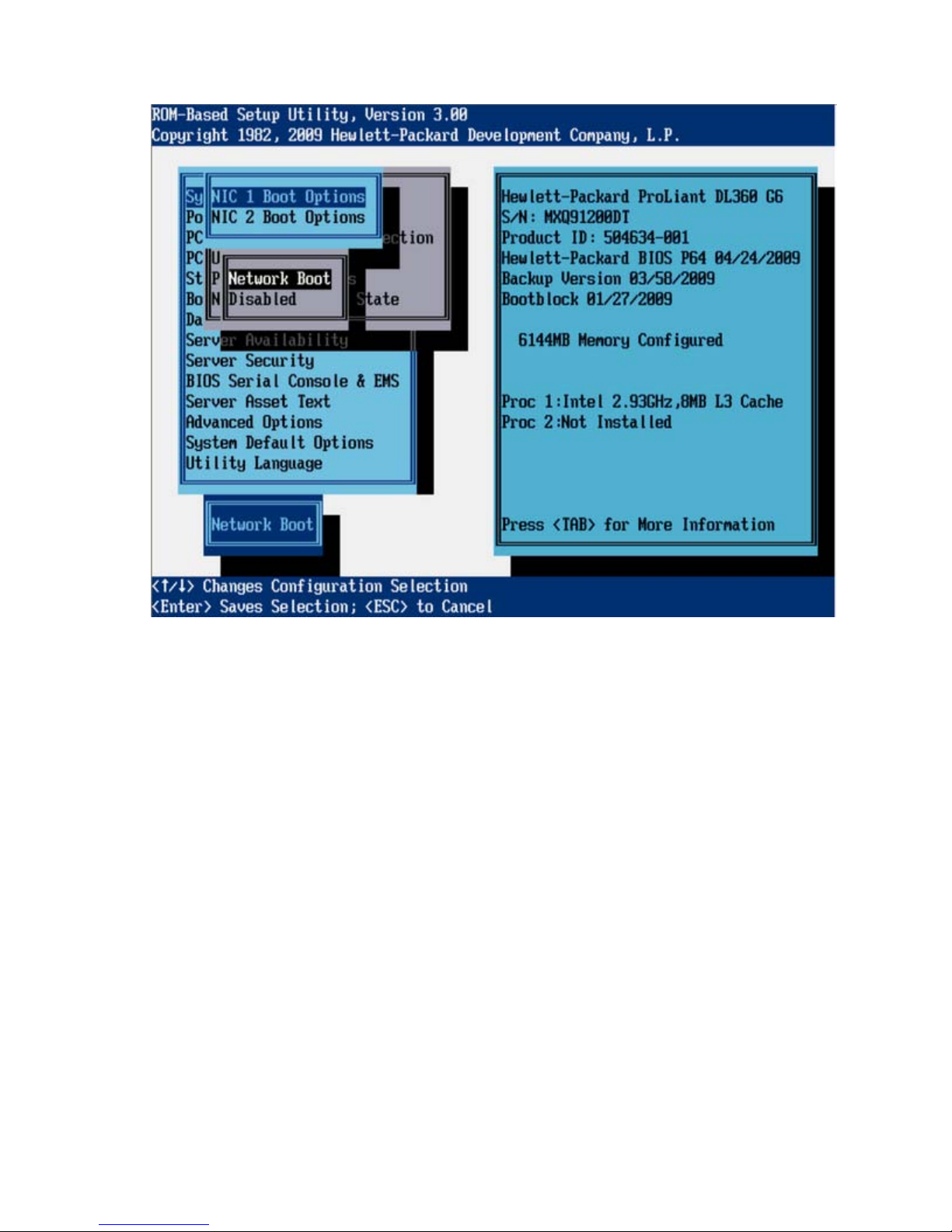
o
Disabled (default)
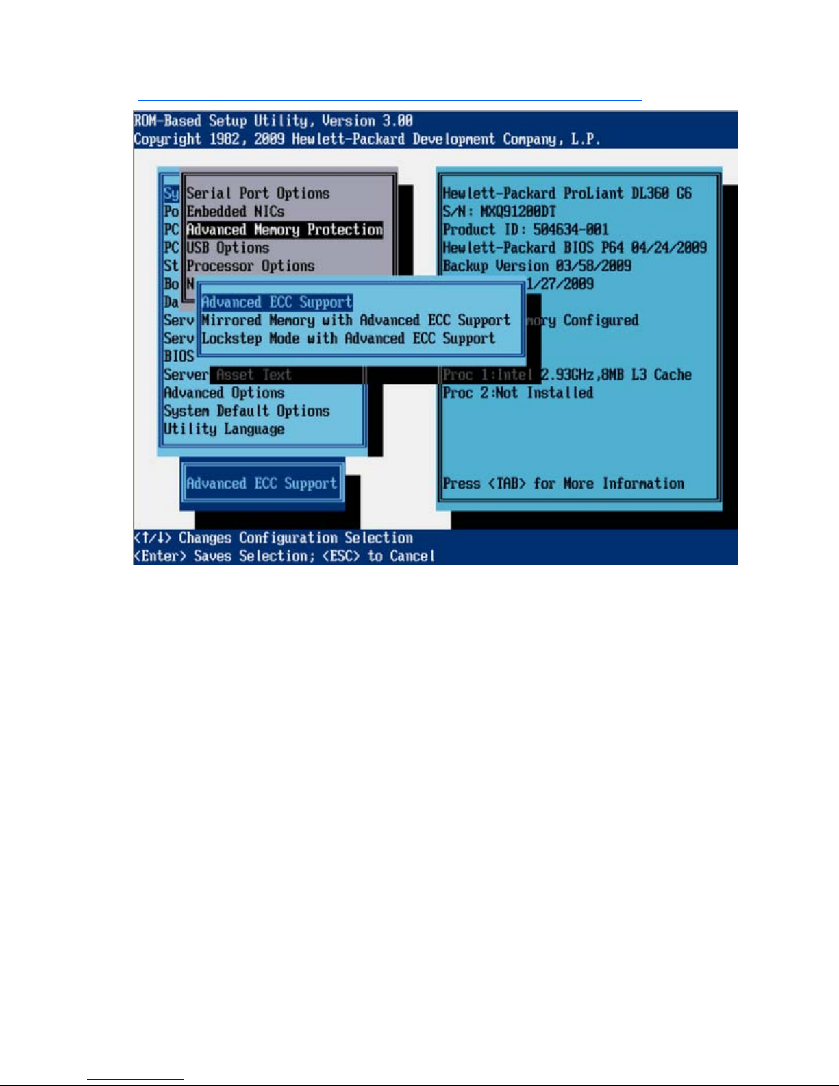
Advanced Memory Protection (G6 servers)
The Advanced Memory Protection option provides the following memory protection modes:
• Advanced ECC provides the largest memory capacity to the OS.
• Lockstep Mode provides increased data protection by enabling multiple-bit memory errors to be
corrected in certain instances not possible in Advanced ECC mode.
• Mirrored Memory provides maximum protection against uncorrectable memory errors that would
otherwise result in system failure.
RBSU menu (HP ProLiant G6 servers or server blades) 13
Page 14
For more information on Advanced Memory Protection, see the HP website
(http://h18004.www1.hp.com/products/servers/technology/memoryprotection.html
).
USB Options (G6 servers)
• USB Control (G6 servers) (on page 14)
• USB 2.0 EHCI Controller (G6 servers) (on page 16)
USB Control (G6 servers)
• Removable Flash Media Boot Sequence (G6 servers) (on page 17)
The USB Control menu determines how USB ports and embedded devices operate at startup:
• When USB Enabled is selected, all USB ports and embedded devices are enabled.
• When USB Disabled is selected, all USB ports and embedded devices are disabled.
• When Legacy USB Disabled is selected, all USB ports are enabled under a USB-aware OS, but USB
is not supported during POST or RBSU. Legacy USB Disabled also disables iLO 2 virtual devices.
RBSU menu (HP ProLiant G6 servers or server blades) 14
Page 15
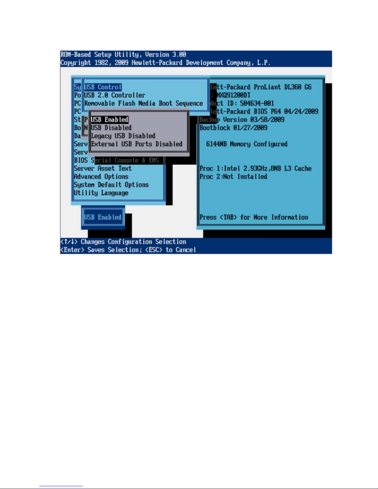
• When External USB Port Disabled is selected, external USB ports are disabled. Under this option,
embedded USB devices still have full support under the ROM and OS.
RBSU menu (HP ProLiant G6 servers or server blades) 15
Page 16

USB 2.0 EHCI Controller (G6 servers)
The USB 2.0 EHCI Controller option is a toggle setting that enables or disables the high-speed USB 2.0
controller.
RBSU menu (HP ProLiant G6 servers or server blades) 16
Page 17
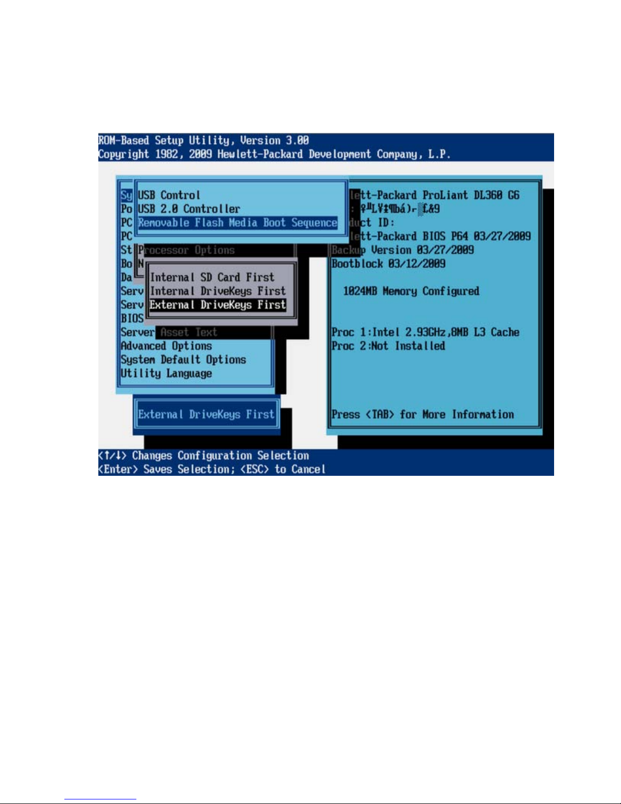
Removable Flash Media Boot Sequence (G6 servers)
This option enables the user to select which USB or SD card devices the system searches first when
enumerating boot devices. The user can select whether the system should attempt to boot from the SD
Card slot first. The option does not override the device boot order selected in the Standard Boot Order
(IPL) option.
Processor Options (G6 servers)
• No-Execute Memory Protection (G6 servers) (on page 17)
• Intel® Virtualization Technology (G6 servers) (on page 18)
• Intel® Hyperthreading® Options (G6 servers) (on page 20)
• Core Disabling Options (G6 servers) (on page 20)
• Turbo Mode (G6 Servers) (on page 21)
No-Execute Memory Protection (G6 servers)
• Intel® VT-d2 (G6 servers) (on page 22)
No-Execute Memory Protection enables the hardware portion of a feature that protects systems against
malicious code and viruses. When used in combination with an OS that supports this feature, certain
memory is marked as not for executable code. Viruses that attempt to insert and execute code from nonexecutable memory locations are intercepted and an exception is raised.
RBSU menu (HP ProLiant G6 servers or server blades) 17
Page 18
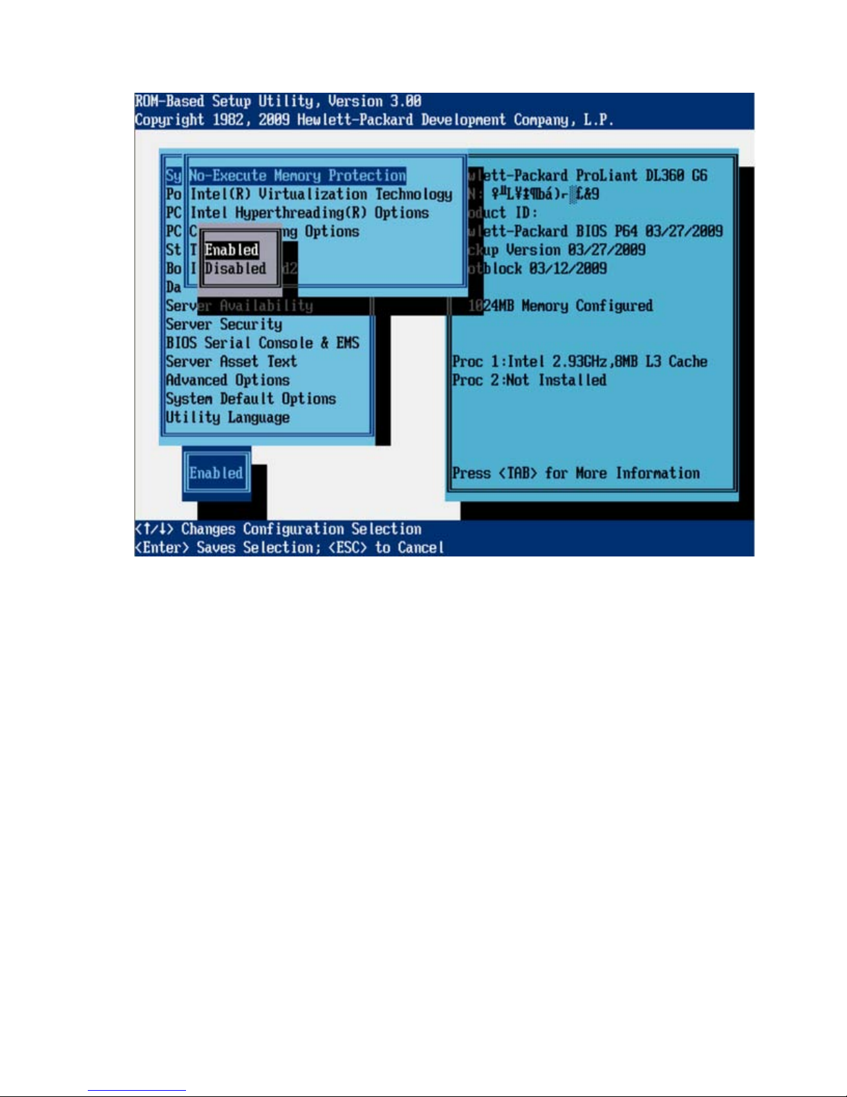
The default setting is Enabled.
Intel® Virtualization Technology (G6 servers)
When enabled, a Virtual Machine Manager supporting this feature can use hardware capabilities
provided by Intel®.
RBSU menu (HP ProLiant G6 servers or server blades) 18
Page 19

The default setting is Enabled.
RBSU menu (HP ProLiant G6 servers or server blades) 19
Page 20
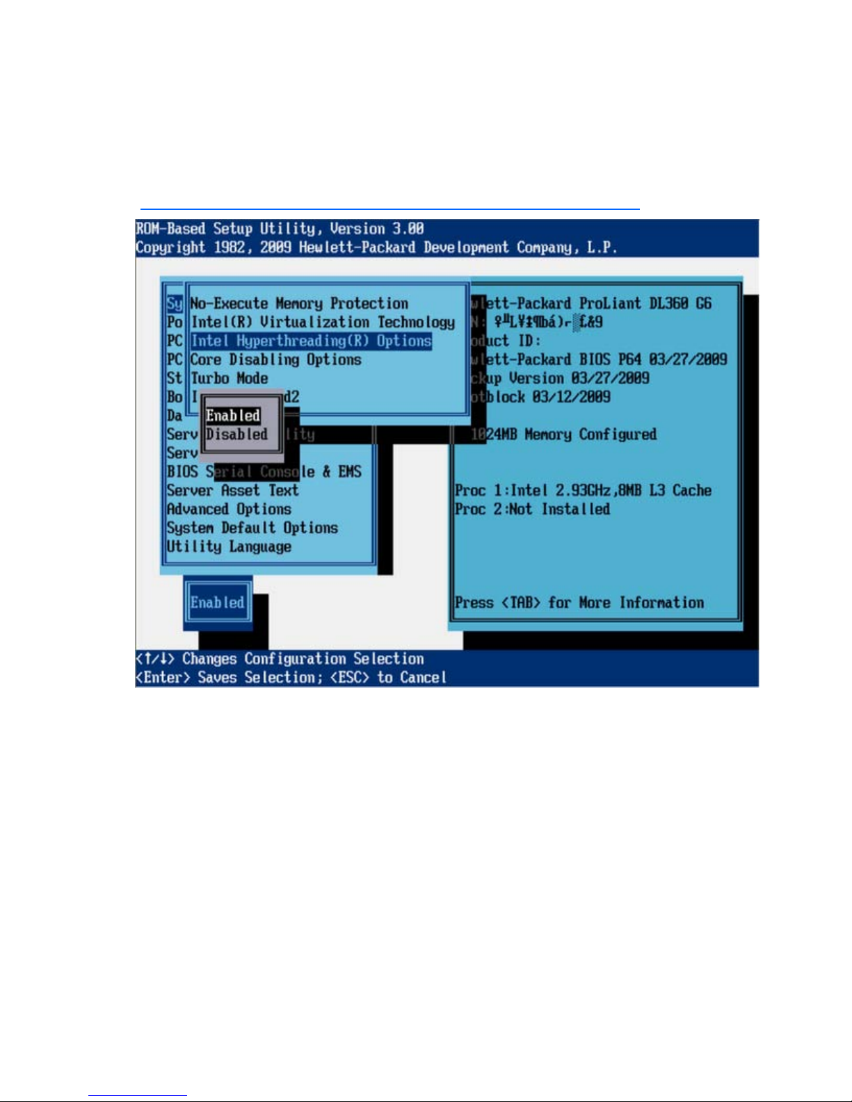
Intel® Hyperthreading® Options (G6 servers)
Intel® Hyperthreading® Options is a toggle setting that allows Intel® Hyperthreading® Technology to be
enabled or disabled, though it is enabled by default. Intel® Hypertreading® delivers two logical
processors that can execute multiple tasks simultaneously using shared hardware resources of a single
processor core. The option is supported through the system BIOS. For more information on Intel®
Hyperthreading®, see the HP website
(http://h18004.www1.hp.com/products/servers/technology/hyper-threading.html
).
Core Disabling Options (G6 servers)
Depending on the applications used, this feature has the following benefits:
• Reduces processor power usage and improves overall performance
• Improves overall performance for applications that benefit from higher performance cores rather than
from additional processing cores
• Addresses issues with software licensed on a per-core basis
RBSU menu (HP ProLiant G6 servers or server blades) 20
Page 21

The default setting is All Cores Enabled.
Turbo Mode (G6 servers)
Turbo Mode enables a processor that has available power headroom and is under temperature
specification to transition to a higher frequency than the rated speed. Disabling this feature reduces
power usage but also reduces the system's maximum achievable performance under some workloads.
RBSU menu (HP ProLiant G6 servers or server blades) 21
Page 22
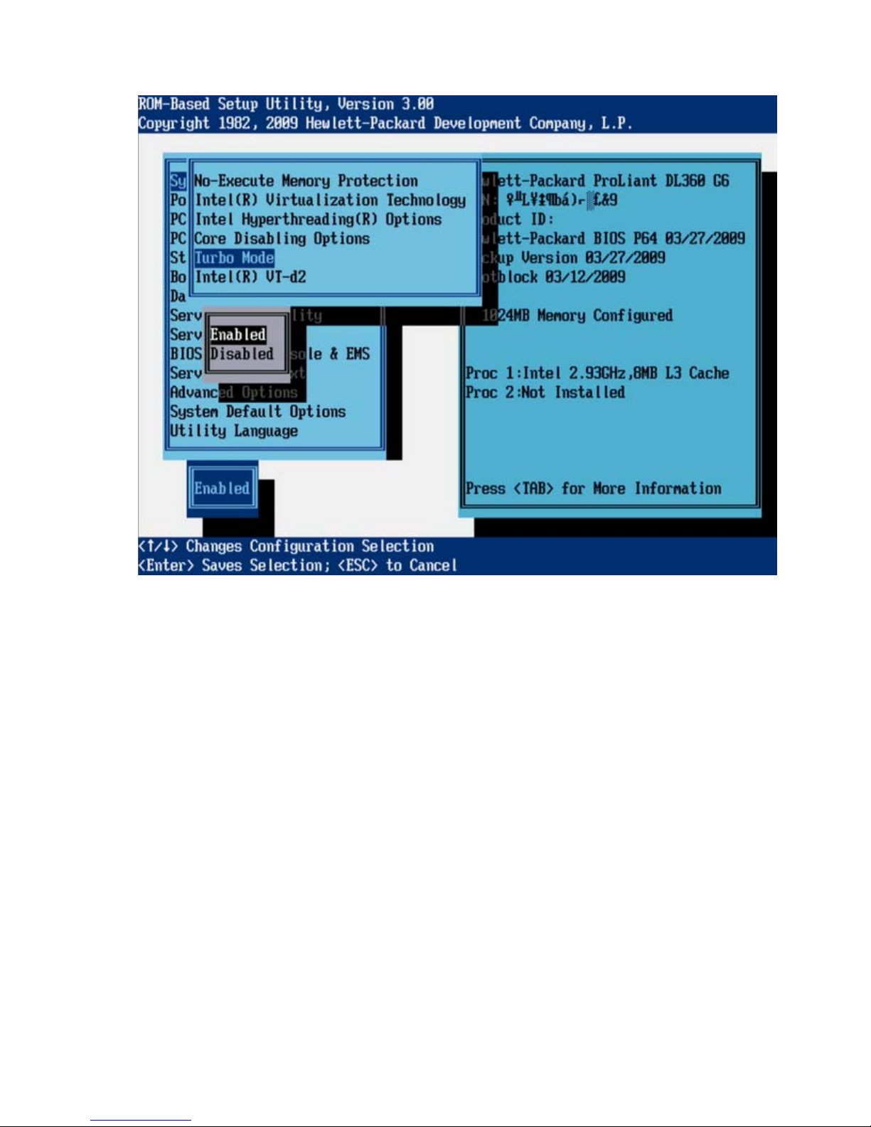
The default setting is Enabled.
Intel® VT-d2 (G6 servers)
When enabled, a Virtual Machine Manager supporting this feature can use hardware capabilities
provided by the Intel® Virtualization Technology for Directed I/O.
RBSU menu (HP ProLiant G6 servers or server blades) 22
Page 23
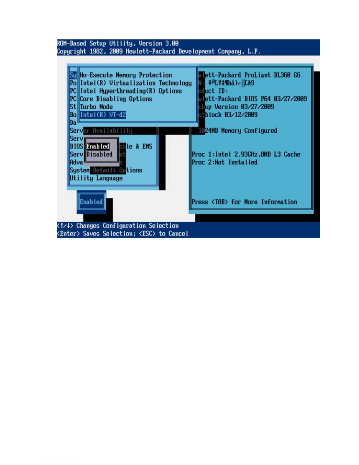
The default setting is Enabled.
RBSU menu (HP ProLiant G6 servers or server blades) 23
Page 24
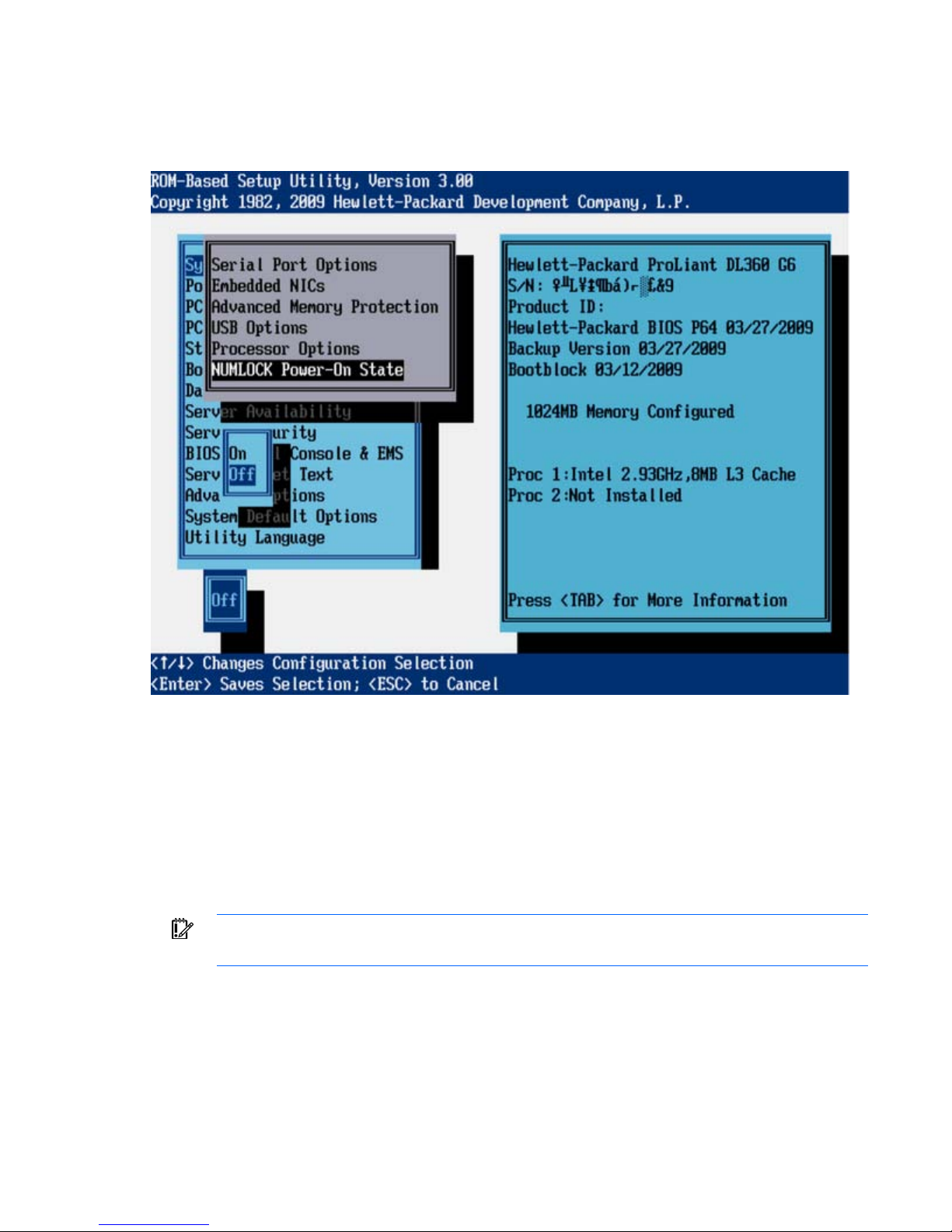
NUMLOCK Power-On State (G6 servers)
The NUMLOCK Power-On State option is a toggle setting that enables or disables the power-up state of
the NUMLOCK key. When the NUMLOCK key is enabled, it is active when the machine powers up.
Power Management Options (G6 servers)
The Power Management Option menu has the following options:
• HP Power Profile (G6 servers) (on page 24)
• HP Power Regulator (G6 servers) (on page 25)
• Redundant Power Supply Mode (G6 servers) (on page 27)
• Advanced Power Management Options (G6 servers) (on page 27)
IMPORTANT: Menu options may differ from those in this document, depending on specific
HP Power Profile (G6 servers)
This option enables the user to select the appropriate power profile based on power and performance
characteristics. The following options are available:
server options.
RBSU menu (HP ProLiant G6 servers or server blades) 24
Page 25
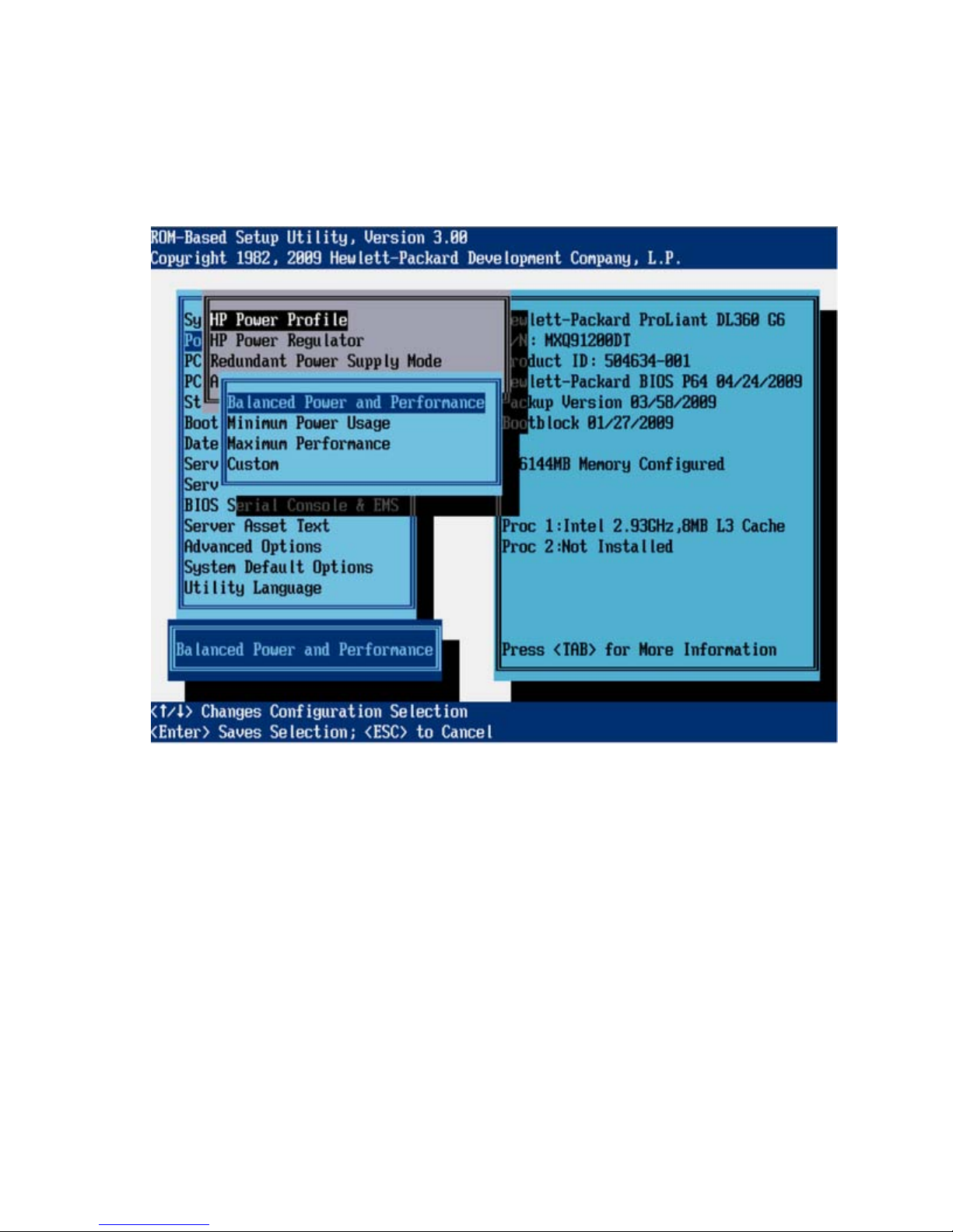
• Balanced Power and Performance provides the optimum settings to maximize power savings with
minimal performance impact for most operating systems and applications.
• Minimum Power Usage enables power reduction mechanisms that may affect performance
negatively. This mode guarantees a lower maximum power usage by the system.
• Maximum Performance disables all power management options that may affect performance
negatively.
HP Power Regulator (G6 servers)
This feature configures the Power Regulator for ProLiant support. The following options are available:
• HP Dynamic Power Savings Mode
o Automatically varies processor speed and power usage based on processor use
o Reduces overall power consumption with little or no impact to performance
o Does not require OS support
• HP Static Low Power Mode
o Reduces processor speed and power usage
o Guarantees a lower maximum power usage for the system
o The impact on performance is greater for environments with higher processor utilization.
• HP Static High Performance Mode
RBSU menu (HP ProLiant G6 servers or server blades) 25
Page 26
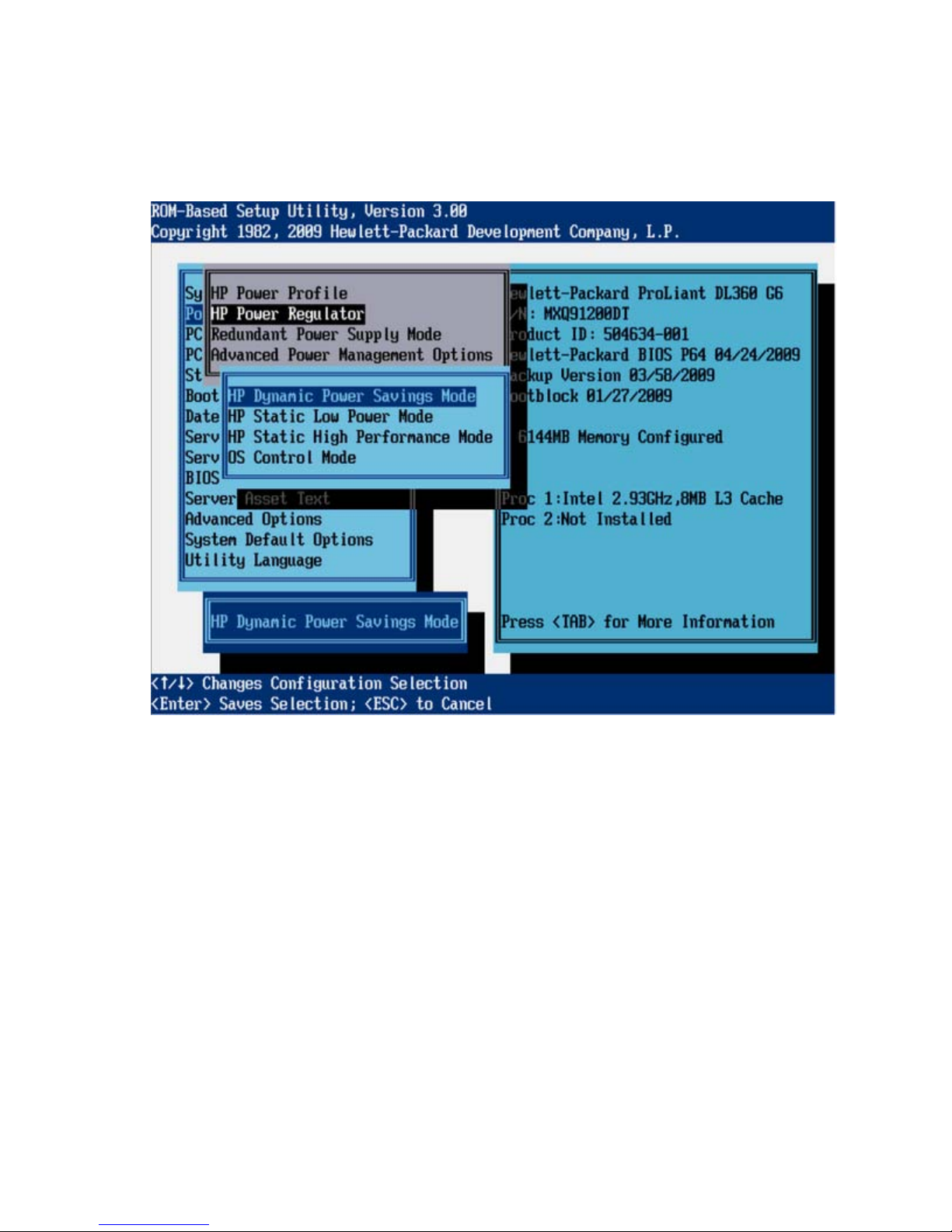
Processors run in the maximum power and performance state, regardless of the OS power
management policy.
• OS Control Mode
Processors run in the maximum power and performance state, unless the OS enables a power
management policy.
RBSU menu (HP ProLiant G6 servers or server blades) 26
Page 27
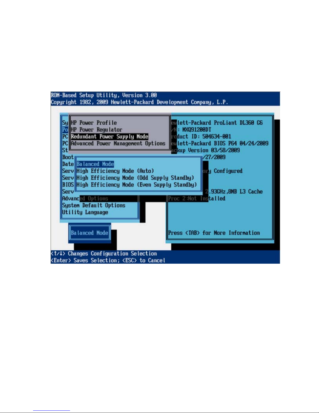
Redundant Power Supply Mode (G6 servers)
This feature enables the user to configure how the system handles redundant power supply configurations.
Balanced Mode shares the power delivery equally between all installed power supplies. All High
Efficiency Mode options provide the most power efficient operation with redundant power supplies by
keeping half of the power supplies in standby mode at lower power usage levels. The High Efficiency
Mode options allow the user to choose which power supply is placed in standby. To achieve a semirandom distribution with a group of systems, Auto chooses between the odd or even power supply based
on the server's serial number.
Advanced Power Management Options (G6 servers)
The Advanced Power Management Options menu configures the following features:
• Intel® QPI Link Power Management (G6 servers) (on page 28)
• Minimum Processor Idle Power State (G6 servers) (on page 29)
• Maximum Memory Bus Frequency (G6 servers) (on page 30)
• Memory Interleaving (G6 servers) (on page 31)
• PCI Express Generation 2.0 Support (G6 servers) (on page 32)
• Dynamic Power Savings Mode Response (G6 servers) (on page 32)
RBSU menu (HP ProLiant G6 servers or server blades) 27
Page 28
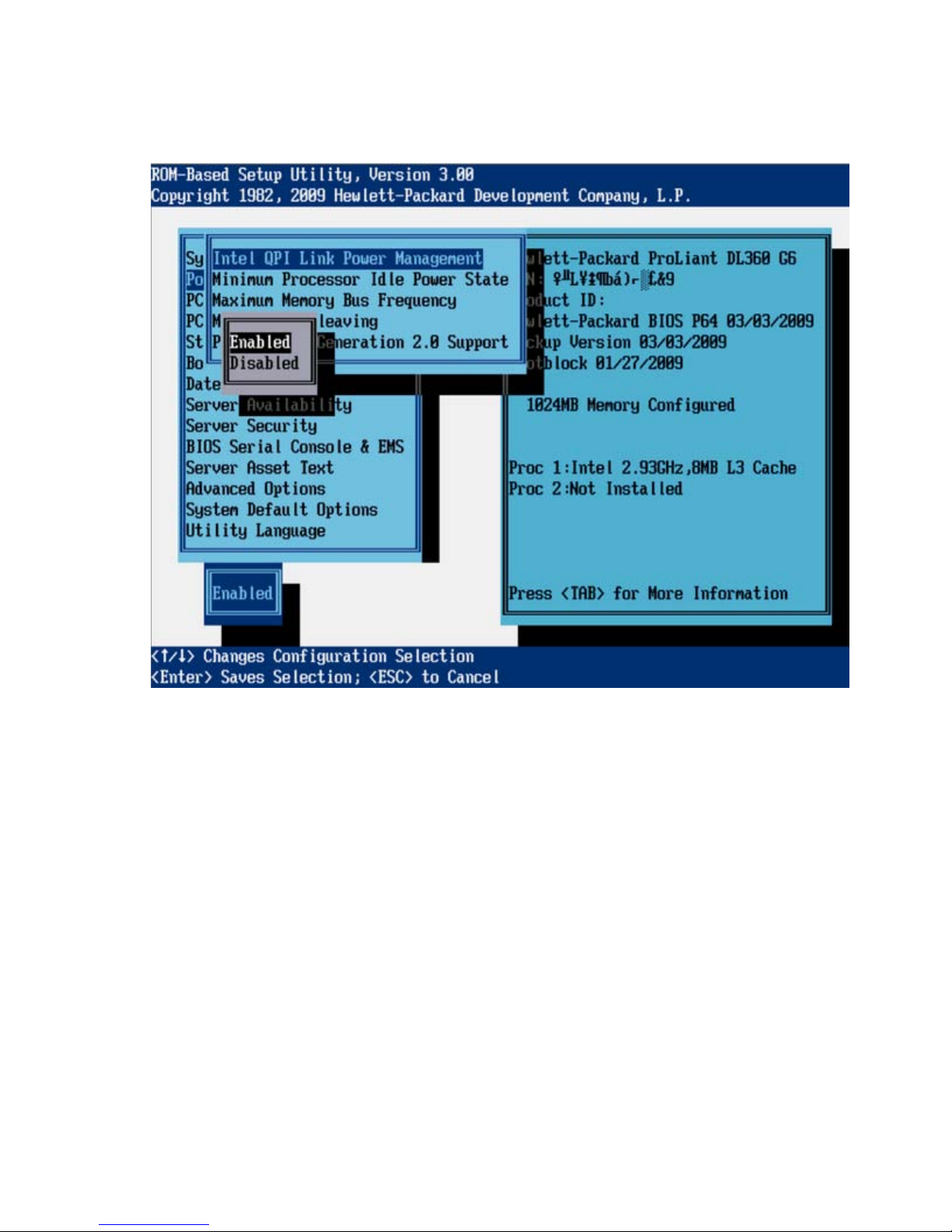
Intel® QPI Link Power Management (G6 servers)
This feature places the Quick Path Interconnect links into a low power state when the links are not being
used. This reduces power usage with minimal performance impact.
RBSU menu (HP ProLiant G6 servers or server blades) 28
Page 29

Minimum Processor Idle Power State (G6 servers)
This feature selects the lowest processor idle power state (C-state) supported by the OS. The higher the Cstate, the lower the power usage of the idle power state. C6 is the lowest power idle state supported by
the processor.
RBSU menu (HP ProLiant G6 servers or server blades) 29
Page 30
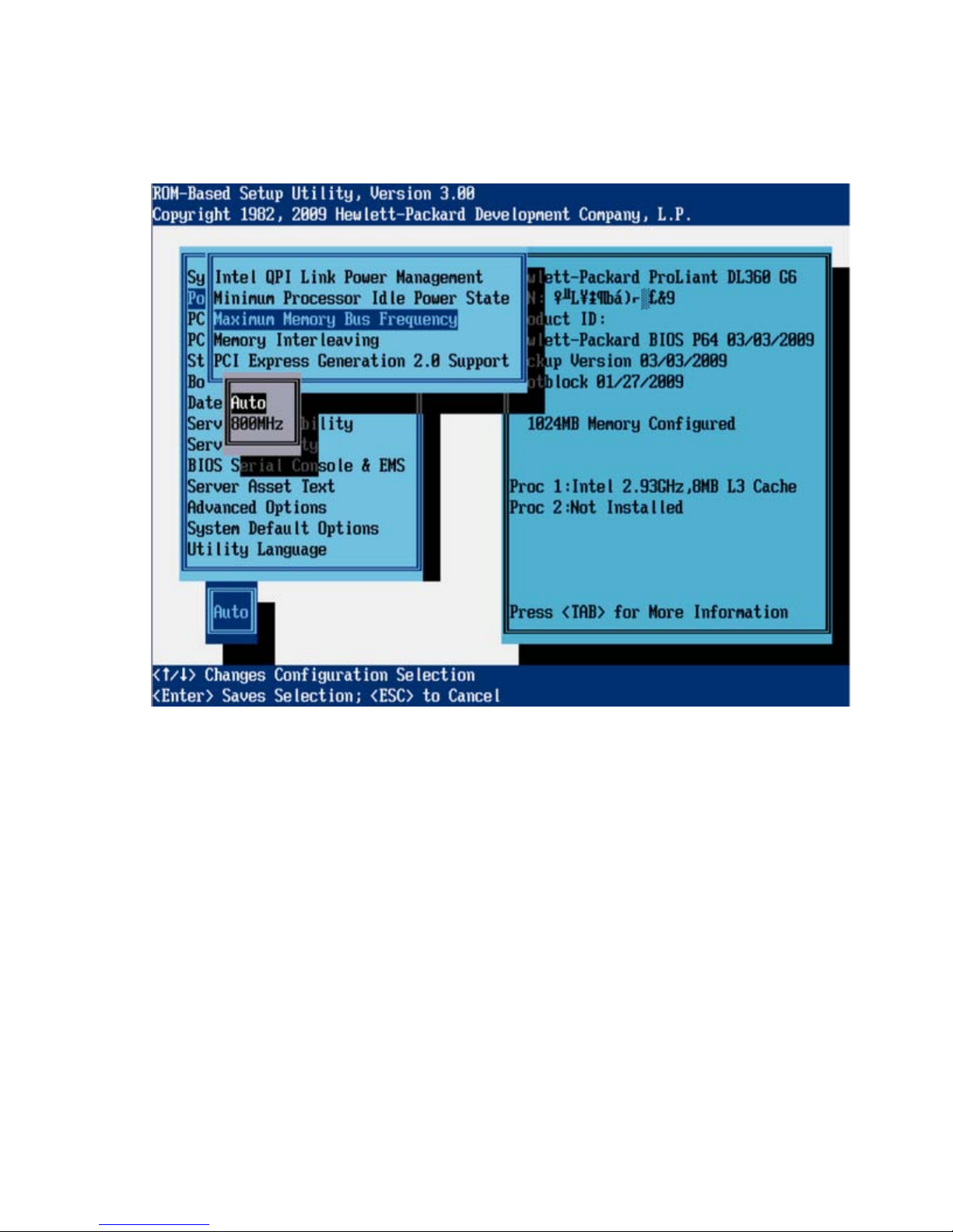
Maximum Memory Bus Frequency (G6 servers)
This feature configures the system to run memory at a lower maximum speed than what is supported by
the installed processor and DIMM configuration. Setting this option to Auto configures the system to run
memory at the maximum speed supported by the system configuration.
RBSU menu (HP ProLiant G6 servers or server blades) 30
Page 31

Memory Interleaving (G6 servers)
This feature modifies the level of interleaving for the memory system configuration. Typically, higher levels
of memory interleaving result in maximum performance. However, reducing the level of interleaving can
result in power savings.
RBSU menu (HP ProLiant G6 servers or server blades) 31
Page 32

PCI Express Generation 2.0 Support (G6 servers)
This feature disables PCIe 2.0 support. If disabled, all PCIe devices in the system operate at PCIe 1.0
speeds (2.5 Gb/s) even if a PCIe device is capable of operating at 2.0 speeds (5.0 Gb/s). This feature
can be used to reduce system power usage. In addition, this feature can be used to work around issues
with devices that claim PCIe 2.0 support but do not adhere to the PCIe 2.0 specification.
Dynamic Power Savings Mode Response (G6 servers)
The Dynamic Power Savings Mode Response feature enables the System ROM to control processor
performance and power state, depending on the processor workload. This option configures the response
time for switching between these states.
RBSU menu (HP ProLiant G6 servers or server blades) 32
Page 33

The Fast setting is optimal for most workloads that require a low latency response to an increase in
processor demand. The slow setting is optimal for some workloads where a longer latency response to
increases in processing demand is an acceptable tradeoff for reduced power consumption. Depending on
the processor workload, selecting this option may negatively impact performance.
RBSU menu (HP ProLiant G6 servers or server blades) 33
Page 34

PCI IRQ Settings (G6 servers)
These options configure the legacy IRQ for embedded and slot-based PCI/PCIe devices. Multiple devices
can share an IRQ.
The PCI Devices menu displays the configuration settings of the PCI devices installed in the server and
allows you to modify the IRQ. Multiple PCI devices can share an interrupt.
To disable a device, select the device and press the Enter key. A menu is displayed with options to
change the IRQ, as well as to disable the device.
PCI Device Enable/Disable (G6 servers)
These options enable and disable embedded devices. Disabling devices reallocates the resources
(memory, I/O, and, in some cases, option ROM space) that would normally be allocated to the device,
and in some cases, saves the power that would be allocated to the device.
NOTE: Only IRQs that are modified in RBSU retain the change during the next reboot. IRQs on
PCI devices that have not been modified are subject to change during reboot.
IMPORTANT: When the PCI Hot Plug driver is installed on servers with Microsoft® Windows®
2000 or Windows Server® 2003, disabling a single PCI controller also disables all controllers
on the same PCI bus. To avoid disabling other controllers on the bus, remove the single PCI
controller.
RBSU menu (HP ProLiant G6 servers or server blades) 34
Page 35

RBSU menu (HP ProLiant G6 servers or server blades) 35
Page 36

Standard boot order (IPL) (G6 servers)
The Standard Boot Order (IPL) option configures the Initial IPL device and controls the search order the
server uses to look for a bootable device.
NOTE: If you enable or disable a device, restart the server. Changes do not take effect until
after reboot.
Boot Controller Order (G6 servers)
The Boot Controller Order option selects which of the installed mass storage devices is used as the
primary boot controller. The server attempts to boot to the OS located on the primary boot controller.
The primary boot controller is set to controller 1.
NOTE: Changes made to the Boot Controller Order in the ORCA Utility are reflected in this
menu.
RBSU menu (HP ProLiant G6 servers or server blades) 36
Page 37

IMPORTANT: PCI devices that have been disabled in the PCI Devices menu are still visible on
the Boot Controller Order screen.
RBSU menu (HP ProLiant G6 servers or server blades) 37
Page 38

Date and Time (G6 servers)
The Date and Time option sets the system time and date. Enter the date in a month-day-year (mm-dd-yyyy)
format. Enter the time in an hour-minute-second (hh:mm:ss) format.
Server Availability (G6 servers)
The Server Availability menu includes options that configure the ASR features:
• ASR Status (G6 servers) (on page 39)
• ASR Timeout (G6 servers) (on page 39)
• Thermal Shutdown (G6 servers) (on page 41)
• Wake-On LAN (G6 servers) (on page 41)
• POST F1 Prompt (G6 servers) (on page 42)
• Power Button (G6 servers) (on page 44)
• Automatic Power-On (G6 servers) (on page 45)
• Power-On Delay (G6 servers) (on page 45)
RBSU menu (HP ProLiant G6 servers or server blades) 38
Page 39

ASR Status (G6 servers)
The ASR Status option is a toggle setting that either enables or disables ASR. When set to Disabled, no
ASR features function.
ASR Timeout (G6 servers)
The ASR Timeout option sets a timeout limit for resetting a server that is not responding. When the server
has not responded in the selected amount of time, the server automatically resets. The following time
increments are available:
• 10 minutes
• 15 minutes
• 20 minutes
• 30 minutes
RBSU menu (HP ProLiant G6 servers or server blades) 39
Page 40

• 5 minutes
RBSU menu (HP ProLiant G6 servers or server blades) 40
Page 41

Thermal Shutdown (G6 servers)
The Thermal Shutdown option is a toggle setting that determines when the server automatically powers
down due to dangerous temperatures. When the setting is enabled (default), the Advanced System
Management driver initiates a system shutdown when the temperature reaches approaches critical level.
When the setting is disabled, the Advanced System Management driver shuts down the system at the
critical level.
Wake-On LAN (G6 servers)
The Wake-On LAN option is a toggle setting that enables or disables the Wake-On LAN feature. When
set to Enabled, the server can be powered up remotely using a network controller. When changing to
Enabled, the following message appears:
RBSU menu (HP ProLiant G6 servers or server blades) 41
Page 42

When enabling Wake-on LAN, remove all power cords before adding or removing
any adapters. Some adapters can cause the system to power on when added or
removed.
POST F1 Prompt (G6 servers)
The POST F1 Prompt option is a toggle setting that configures the server so the F1 key must be pressed to
proceed when an error occurs during the power-up sequence. A series of system tests executes during
POST before continuing with the following:
• If failures occur that allow the system to continue operating, the system continues to boot but posts a
message.
• If critical components fail or are missing, the server attempts to boot. If it can boot, it posts a
message and an F1 prompt.
o If Enabled is selected and an error occurs, the system stops at the F1 prompt until the F1 key is
pressed, before continuing to boot.
o If Delayed is selected and an error occurs, the system pauses for 20 seconds at the F1 prompt,
and then continues to boot the OS.
• If the system cannot run with the missing or failed components, it halts until those components are
replaced.
RBSU menu (HP ProLiant G6 servers or server blades) 42
Page 43

The POST F1 Prompt setting is delayed by default in ProLiant BL, ML, and DL servers.
RBSU menu (HP ProLiant G6 servers or server blades) 43
Page 44

Power Button (G6 servers)
Disabling the Power Button feature causes the momentary power button to stop functioning under any OS.
The Power Button feature does not override the 4-second hold-down of the server power button.
RBSU menu (HP ProLiant G6 servers or server blades) 44
Page 45

Automatic Power-On (G6 servers)
The Automatic Power-On feature enables the server to automatically power on when auxiliary power is
applied to the server.
Power-On Delay (G6 servers)
When multiple servers power up after a power loss, the Power-On Delay feature delays the server from
powering on for a specified time to prevent power usage spikes. Wake-on LAN, RTC wake-up, and iLO
Virtual Power Button events override the delay and immediately power on the server.
The following Power-On Delay options are available:
• Disabled
• 15-second delay
• 30-second delay
• 45-second delay
• 60-second delay
RBSU menu (HP ProLiant G6 servers or server blades) 45
Page 46

• Random delay
Server Security (G6 servers)
The Server Passwords menu includes options that configure the password environment of the server:
• Set Power-On Password (G6 servers) (on page 47)
• Set Admin Password (G6 servers) (on page 48)
• Trusted Platform Module (G6 servers) (on page 48)
RBSU menu (HP ProLiant G6 servers or server blades) 46
Page 47

Set Power-On Password (G6 servers)
The Set Power-On Password option sets a password that controls access to the server during power-up.
The server cannot be powered up until the correct password is entered. The Set Power-On Password
option uses a simple character string with a maximum of seven characters. To disable or clear the
password, enter the password followed by a / (slash) when prompted to enter the password.
RBSU menu (HP ProLiant G6 servers or server blades) 47
Page 48

Set Admin Password (G6 servers)
The Set Admin Password option sets a password to control access to the administrative features of the
server. The Set Admin Password option is a simple character string with a maximum of seven characters.
To disable or clear the password, enter the password followed by a / (slash) when prompted to enter the
password.
Trusted Platform Module (G6 servers)
The Trusted Platform Module menu includes options that configure the optional Trusted Platform Module
installed on HP ProLiant Generation 6 Servers:
• TPM Functionality (G6 servers) (on page 49)
• TPM Visibility (G6 servers) (on page 49)
• TPM Expansion ROM Measuring (G6 servers) (on page 51)
• TPM Clear (G6 servers) (on page 51)
IMPORTANT: The TPM menus appear only if the TPM kit is installed.
RBSU menu (HP ProLiant G6 servers or server blades) 48
Page 49

TPM Functionality (G6 servers)
Enabling TPM Functionality enables the TPM and BIOS secure startup. The TPM is fully functional in this
mode.
CAUTION: When a TPM is installed and enabled on the server, data access is locked (if the
TPM is being used by the OS) if you fail to follow the proper procedures for updating the
system or option firmware, replacing the system board, replacing a hard drive, or modifying
For information on installing and enabling the TPM module option, see the HP Trusted Platform Module
Option Installation Instructions that ships with the option.
Disabling TPM Functionality disables the BIOS secure startup but still allows the TPM to be visible to the
operating system. The TPM can respond to most commands in this mode.
Selecting Disabled may prevent the server from booting to a TPM-aware operating system.
OS application TPM settings.
TPM Visibility (G6 servers)
The TPM Visibility option provides the ability to hide the TPM from the operating system. When the TPM is
hidden, BIOS secure startup is disabled, and the TPM does not respond to any commands from any
software.
RBSU menu (HP ProLiant G6 servers or server blades) 49
Page 50

Hiding the TPM may prevent the server from booting to a TPM-aware operating system.
RBSU menu (HP ProLiant G6 servers or server blades) 50
Page 51
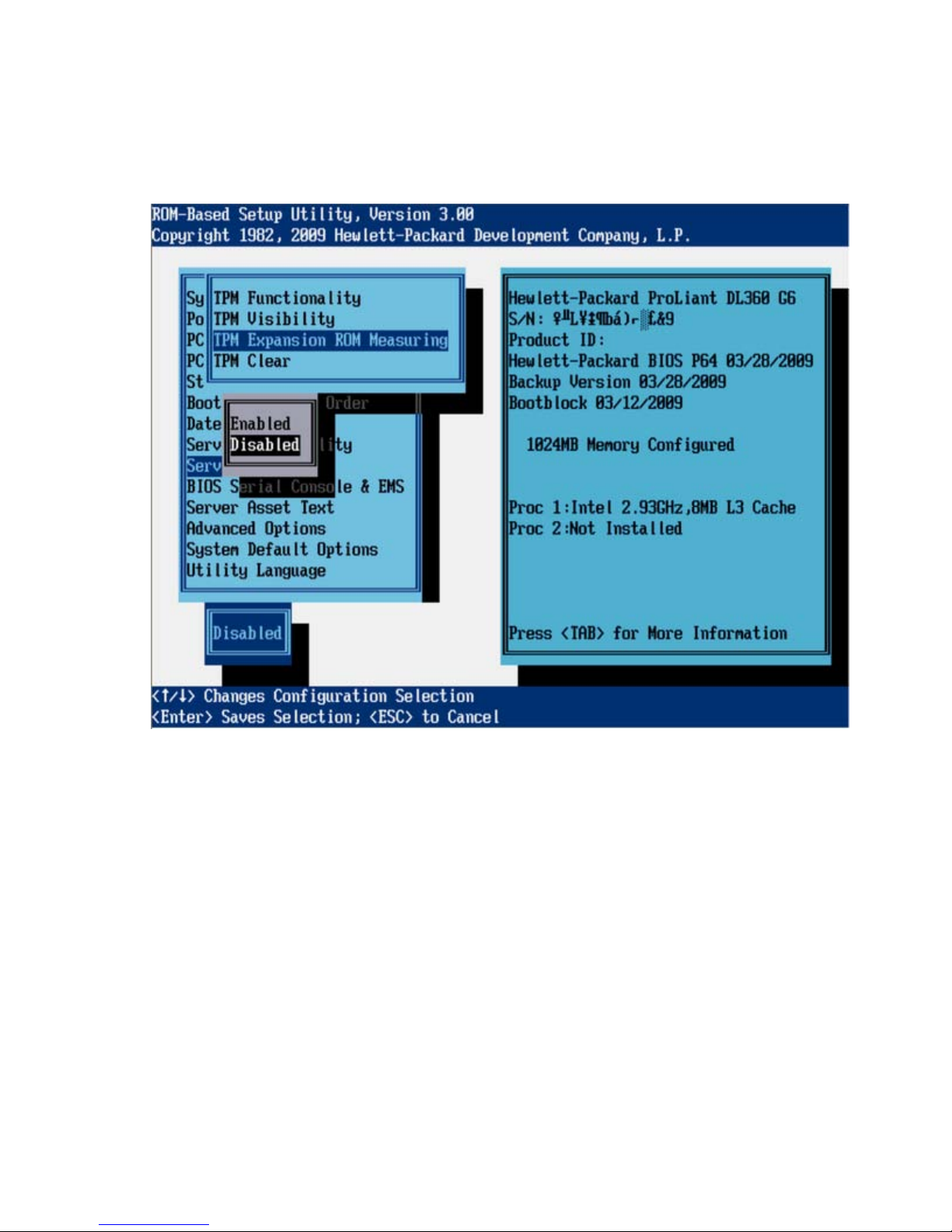
TPM Expansion ROM Measuring (G6 servers)
TPM Expansion ROM Measuring enables the BIOS to measure the optional PCI or PCIe expansion ROM
code and store that measurement in the TPM. On subsequent reboots, operating systems or validation
software applications that utilize the measurements stored in the TPM can use this data to detect
modifcations to PCI or PCIe expansion ROM versions.
TPM Clear (G6 servers)
The TPM Clear option allows the user to reset the TPM to factory settings, clearing any assigned
passwords, keys, or ownership.
RBSU menu (HP ProLiant G6 servers or server blades) 51
Page 52

Clearing the TPM may prevent the server from booting to a TPM-aware operating system.
BIOS Serial Console/EMS Support (G6 servers)
IMPORTANT: Some languages or characters may require a specific emulation mode.
The BIOS Serial Console/EMS Support option configures the serial port to view POST error messages and
runs RBSU remotely through a serial connection to the server COM port or iLO 2 Virtual serial port. The
remote server does not require a keyboard or mouse.
For more information about BIOS Serial Console, see the BIOS Serial Console User Guide on the
Documentation CD or the HP website (http://www.hp.com/support/smartstart/documentation
BIOS Serial Console design supports VT100+ emulation. For more information, see "Command Line
Interface Overview (on page 119)."
When viewed in BIOS Serial Console, the RBSU main menu looks slightly different from the local server
view.
The following menu options are available:
• BIOS Serial Console Port (G6 servers) (on page 53)
• BIOS Serial Console Baud Rate (G6 servers) (on page 54)
).
• EMS Console (G6 servers) (on page 55)
RBSU menu (HP ProLiant G6 servers or server blades) 52
Page 53

• BIOS Interface Mode (G6 servers) (on page 56)
BIOS Serial Console Port (G6 servers)
The BIOS Serial Console Port option provides additional selections for enabling BIOS Serial Console.
RBSU menu (HP ProLiant G6 servers or server blades) 53
Page 54

BIOS Serial Console Baud Rate (G6 servers)
The BIOS Serial Console Baud Rate option enables baud rate changes.
RBSU menu (HP ProLiant G6 servers or server blades) 54
Page 55

EMS Console (G6 servers)
The EMS Console option is a Microsoft® Windows Server® 2003 feature that enables the emergency
management console to be redirected through the serial port. When using iLO, select the value (COM 1
or COM 2) assigned to the Virtual Serial Port (on page 85). When redirecting EMS through a physical
serial port, select the value assigned to the Embedded Serial Port ("Embedded Serial Port A" on page
84). The EMS Console feature is disabled by default.
RBSU menu (HP ProLiant G6 servers or server blades) 55
Page 56

BIOS Interface Mode (G6 servers)
When Auto mode is selected, CLI mode is automatically selected during POST if the keyboard buffer
receives characters from the serial port instead of the keyboard. When Command-Line mode is selected,
CLI mode is automatically enabled.
Server Asset Text (G6 servers)
The Server Asset Text menu includes options that customize the system-specific text for the server. The
following menu options are available:
• Set Server Info Text (G6 servers) (on page 57)
• Set Administrator Info Text (G6 servers) (on page 58)
• Set Service Contact Text (G6 servers) (on page 59)
• Custom POST Message (G6 servers) (on page 60)
RBSU menu (HP ProLiant G6 servers or server blades) 56
Page 57

Set Server Info Text (G6 servers)
The Set Server Info Text option defines reference information for the server. The setting is blank by default.
• Server Name defines a two-line name identifying the server. A maximum of 14 characters can be
entered on each line.
• Server Asset Tag defines a two-line asset tag to identify the server. A maximum of 16 characters can
be entered on each line.
• Server Primary OS defines a three-line description of the primary OS of the server. A maximum of 14
characters can be entered on each line.
• Other Text defines two lines of additional text describing the server. A maximum of 14 characters
can be entered on each line.
RBSU menu (HP ProLiant G6 servers or server blades) 57
Page 58

Set Administrator Info Text (G6 servers)
The Set Administrator Info Text option defines reference information for the server administrator.
• Admin Name Text defines a two-line description for the server administrator name. A maximum of
14 characters can be entered on each line.
• Admin Phone Number Text defines two lines of text for the server administrator phone number. A
maximum of 14 characters can be entered on each line.
• Admin Pager Number Text defines two lines of text for the server administrator pager number. A
maximum of 14 characters can be entered on each line.
• Other Text defines two lines of additional text relating to the server administrator. A maximum of 14
characters can be entered on each line.
RBSU menu (HP ProLiant G6 servers or server blades) 58
Page 59

Set Service Contact Text (G6 servers)
The Set Service Contact Text option defines reference information for the service contact of the server.
• Service Name Text defines a two-line description for the service contact name. A maximum of 14
characters can be entered on each line.
• Service Phone Number Text defines two lines of text for the service contact phone number. A
maximum of 14 characters can be entered on each line.
• Service Pager Number Text defines two lines of text for the service contact pager number. A
maximum of 14 characters can be entered on each line.
• Other Text defines two lines of additional text relating to the service contact. A maximum of 14
characters can be entered on each line.
RBSU menu (HP ProLiant G6 servers or server blades) 59
Page 60

Custom POST Message (G6 servers)
The Custom POST Message option enables the user to enter a custom message to display during POST.
Advanced Options Menu (G6 servers)
The Advanced Options menu includes the following options:
• Advanced System ROM Options (G6 servers) (on page 61)
• Video Options (G6 servers) (on page 68)
• Thermal Configuration (G6 servers) (on page 68)
• Service Options (G6 servers) (on page 69)
• Advanced Performance Tuning Options (G6 servers) (on page 71)
• Drive Write Cache (G6 servers) (on page 75)
• Asset Tag Protection (G6 servers) (on page 76)
IMPORTANT: Menu options may differ from those in this document, depending on specific
server options.
RBSU menu (HP ProLiant G6 servers or server blades) 60
Page 61

Advanced System ROM Options (G6 servers)
• Option ROM Loading Sequence (G6 servers) (on page 61)
• MPS Table Mode (G6 servers) (on page 61)
• ROM Selection (G6 servers) (on page 63)
• NMI Debug Button (G6 servers) (on page 63)
• Virtual Install Disk (G6 servers) (on page 64)
• PCI Bus Padding Options (G6 servers) (on page 65)
• Power-On Logo (G6 servers) (on page 67)
Option ROM Loading Sequence (G6 servers)
This feature enables the user to select whether the option ROM for embedded devices or expansion
boards loads first. This feature addresses issues such as when the PXE option ROM for the embedded NIC
does not load because of a lack of available option ROM space.
MPS Table Mode (G6 servers)
The MPS Table Mode is used to interrupt routing. Certain unsupported operating systems may require
setting the MPS Table to Disabled. For all supported operating systems, this feature can remain enabled
and, in some cases, it is required to be enabled.
RBSU menu (HP ProLiant G6 servers or server blades) 61
Page 62

IMPORTANT: This setting is pre-selected. You can override the default setting at this menu, but
successful OS operation is dependent upon the correct (default) setting.
RBSU menu (HP ProLiant G6 servers or server blades) 62
Page 63

ROM Selection (G6 servers)
The ROM Selection option toggles the server ROM between the current ROM and the backup ROM. All
servers with redundant ROMs allow you to switch to the backup ROM.
NMI Debug Button (G6 servers)
The NMI Debug Button option is a toggle setting that allows you to enable debug functionality when the
system has experienced a software lock-up. The NMI Debug Button generates an NMI to enable the use
of the OS debugger.
WARNING: When enabled, pressing the NMI Debug Button on the system board during
normal OS operation generates a Blue-Screen Trap, ABEND, or Panic, and halts the system.
RBSU menu (HP ProLiant G6 servers or server blades) 63
Page 64

Virtual Install Disk (G6 Servers)
The Virtual Install Disk includes 32- and 64-bit Microsoft® Windows Server® 2003 drivers for boot
devices, which may be necessary to complete the operating system installation. When the Virtual Install
Disk option is enabled, Microsoft® Windows Server® 2003 automatically locates the required drivers
and installs them, eliminating both the need for user intervention and the requirement that a driver be
present on external media during OS installation.
RBSU menu (HP ProLiant G6 servers or server blades) 64
Page 65

To further optimize the system, HP recommends updating these boot drivers to the latest versions after the
OS installation. This functionality is not available with Microsoft® Windows Server® 2008.
PCI Bus Padding Options (G6 servers)
This option allows the user to disable the default PCI Bus padding where each expansion slot is provided
with an extra PCI Bus number. By default, the System ROM pads bus numbers for slots such that adding
expansion cards does not affect the bus numbering of devices in the system. Disabling this option works
around issues with certain expansion cards.
RBSU menu (HP ProLiant G6 servers or server blades) 65
Page 66

HP recommends that you do not disable this option unless you encounter a specific issue.
RBSU menu (HP ProLiant G6 servers or server blades) 66
Page 67

Power-On Logo (G6 servers)
This option disables the display of the logo during system boot. This is an aesthetic modification only and
does not affect the system boot times.
RBSU menu (HP ProLiant G6 servers or server blades) 67
Page 68

Video Options (G6 servers)
By default, the System ROM disables the embedded video controller when an optional video controller is
installed in the system. With this option, the embedded video controller remains enabled for iLO remote
video functionality or for dual-head video support.
Thermal Configuration (G6 servers)
This feature enables the user to select the fan cooling solution for the system:
• Optimal Cooling provides the most efficient solution by configuring fan speeds to the minimum
required to provide adequate cooling.
• Increased Cooling operates fans at higher speeds to provide additional cooling.
RBSU menu (HP ProLiant G6 servers or server blades) 68
Page 69

HP recommends selecting Increased Cooling when storage controllers not manufactured by HP are
connected to the embedded hard drive cage, or if the system is experiencing thermal issues that cannot
be resolved in another manner.
Service Options (G6 servers)
• Serial Number (G6 servers) (on page 69)
Serial Number (G6 servers)
• Product ID (G6 servers) (on page 70)
The Serial Number option enables service personnel to change the serial number. HP recommends that
you do not change this number unless you are replacing a system board. When the Serial Number option
is chosen, the following message appears:
RBSU menu (HP ProLiant G6 servers or server blades) 69
Page 70

The serial number should ONLY be modified by qualified service personnel.
This value should always match the serial number located on the chassis.
Product ID (G6 servers)
The Product ID option sets the system product ID, which is found on the product ID sticker on the chassis.
When the Product ID option is chosen, the following message appears:
RBSU menu (HP ProLiant G6 servers or server blades) 70
Page 71

The Product ID should ONLY be modified by qualified service personnel. This
value should always match the Product ID located on the chassis.
Advanced Performance Tuning Options (G6 servers)
• HW Prefetcher (G6 servers) (on page 72)
• Adjacent Sector Prefetch (G6 servers) (on page 73)
• Enable Node Interleaving (G6 servers) (on page 74)
• Memory Speed with 2 DIMMs per Channel (G6 servers) (on page 74)
RBSU menu (HP ProLiant G6 servers or server blades) 71
Page 72

HW Prefetcher (G6 servers)
The HW Prefetcher option allows processor prefetch features to be disabled. In most cases, the option
should remain enabled. The option should be disabled only after performing application benchmarking to
verify improved performance in a particular environment.
RBSU menu (HP ProLiant G6 servers or server blades) 72
Page 73

Adjacent Sector Prefetch (G6 servers)
The Adjacent Sector Prefetch option allows processor prefetch features to be disabled. In most cases, the
option should remain enabled. The option should be disabled only after performing application
benchmarking to verify improved performance in a particular environment.
RBSU menu (HP ProLiant G6 servers or server blades) 73
Page 74

Enable Node Interleaving (G6 servers)
Enabling Node Interleaving disables the NUMA architecture properties of the system. All operating
systems supported by this platform support NUMA architectures. In most cases, you can obtain optimum
performance by disabling Node Interleaving. When this option is enabled, memory addresses are
interleaved across the memory installed for each processor. When this option is enabled, some workloads
may see improved performance.
Memory Speed with 2 DIMMs per Channel (G6 servers)
This option configures the system to run DIMMs at 1333 MHz when up to two DIMMs are installed on a
memory channel, if all other requirements for 1333 MHz operation are met. This provides a performance
increase for most workloads. By default, the system will operate at a maximum 1066 MHz when two
DIMMs are installed on any memory channel. HP has validated this functionality with all HP DIMMs.
HP recommends that this setting remain at the default of 1066 MHz maximum when using DIMMs not
manufactured by HP.
RBSU menu (HP ProLiant G6 servers or server blades) 74
Page 75

The default setting is 1066 MHz maximum.
Drive Write Cache (G6 servers)
The Drive Write Cache option controls the state of the write cache of the drives attached to the supported
controller. This feature provides greater drive performance but could result in data corruption during an
unexpected power loss or shutdown. When the Drive Write Cache option is enabled, the following
message appears:
Enabling Drive Write Cache may result in data loss or data corruption if an
unexpected power loss occurs.
RBSU menu (HP ProLiant G6 servers or server blades) 75
Page 76

This option only affects operation for fixed drives attached to the embedded SATA controller when not
operating in a software RAID mode. This option has no effect if fixed drives are attached to an embedded
or optional Smart Array controller or if the Smart Array B110i Software RAID solution is used.
Asset Tag Protection (G6 servers)
This option locks the Asset Tag information. When the Asset Tag information is locked, the Asset tag is not
erased if the default system settings are restored.
RBSU menu (HP ProLiant G6 servers or server blades) 76
Page 77

The default setting is Unlocked.
System Default Options (G6 servers)
• Restore Default System Settings (G6 servers) (on page 78)
• Restore Settings/Erase Boot Disk (G6 servers) (on page 79)
• User Default Options (G6 servers) (on page 80)
RBSU menu (HP ProLiant G6 servers or server blades) 77
Page 78

Restore Default System Settings (G6 servers)
This option resets all configuration settings to their default values. All RBSU changes that have been made
are lost.
RBSU menu (HP ProLiant G6 servers or server blades) 78
Page 79

Restore Settings/Erase Boot Disk (G6 servers)
The Restore Settings/Erase Boot Disk option resets the date, time, and all configuration settings to default
values. Data on the boot disk drive is erased, and changes that have been made are lost.
RBSU menu (HP ProLiant G6 servers or server blades) 79
Page 80

User Default Options (G6 servers)
This feature enables the user to define custom default configuration settings. When the default
configuration settings are loaded, the user-defined default settings are used instead of the factory defaults.
To save the configuration as the default configuration, configure the system and then enable this feature.
RBSU menu (HP ProLiant G6 servers or server blades) 80
Page 81

Utility Language (G6 servers)
The Utility Language menu enables you to set the display language for RBSU.
RBSU menu (HP ProLiant G6 servers or server blades) 81
Page 82

RBSU menu (HP ProLiant G5 and earlier servers
or server blades)
RBSU menu overview
The RBSU menu lists configuration settings to view or modify.
IMPORTANT: Menu options may differ from those in this document, depending on specific
On the right-hand side of the screen, a window displays basic server information, including the server
model, serial number, BIOS version, backup BIOS version, memory installed, and processors installed.
server options.
NOTE: A service number is reported below the serial number on the HP ProLiant DL760 Server
only.
NOTE: Pressing the F1 key when any sub-menu option is highlighted allows you to view a
description of that feature. Please note that all menus are in English only.
RBSU menu (HP ProLiant G5 and earlier servers or server blades) 82
Page 83

Some new servers, which use CLI and are configured using BIOS Serial Console, display a command
prompt screen.
The CLI mode of RBSU ("CLI Mode Selection" on page 119) is a command-prompted interface that
provides equivalent functionality to the menu-based mode.
System Options
The System Options menu enables basic I/O server configuration with the following options:
• Embedded Serial Port A (on page 84)
• Embedded Serial Port B (on page 84)
• Virtual Serial Port (on page 85)
• Optional LPT Port (on page 86)
• Optional LPT Mode Support (on page 86)
• Integrated Diskette Controller (on page 86)
• NUMLOCK Power-On State (on page 86)
• Embedded NICs (on page 87)
• Diskette Write Control (on page 87)
• Diskette Boot Control (on page 87)
• Advanced Memory Protection (on page 87)
• USB Control (on page 88)
• USB 2.0 EHCI Controller (on page 89)
• Power Regulator for ProLiant (on page 89)
• USB External Port Capability (on page 90)
• Ultra Low Power State (on page 91)
RBSU menu (HP ProLiant G5 and earlier servers or server blades) 83
Page 84

IMPORTANT: Menu options may differ from those in this document, depending on specific
server options.
Embedded Serial Port A
The Embedded Serial Port A option sets the configuration for the internal serial port A. The settings include
the address and IRQ. This option can also disable the port.
NOTE: Embedded Serial Port options may be named Embedded COM Port options,
depending on the server.
Embedded Serial Port B
The Embedded Serial Port B option sets the configuration for the internal serial port B. The settings include
the address and IRQ. This option can also disable the port.
NOTE: Embedded Serial Port options may be named Embedded COM Port options,
depending on the server.
RBSU menu (HP ProLiant G5 and earlier servers or server blades) 84
Page 85

Virtual Serial Port
The Virtual Serial Port option assigns the logical COM Port number and associated default resources used
by the Virtual Serial Port. When enabled, the option provides remote access through the iLO management
controller to BIOS Serial Console.
NOTE: The Virtual Serial Port option requires iLO Firmware version 1.55 or later.
RBSU menu (HP ProLiant G5 and earlier servers or server blades) 85
Page 86

For detailed information about iLO configurations, refer to the HP Integrated Lights-Out User Guide on the
Documentation CD or to the HP website (http://www.hp.com/servers/lights-out
Optional LPT Port
The Optional LPT Port option sets the configuration for the internal LPT port. The settings include the
address and IRQ. This option can also disable the port.
).
Optional LPT Mode Support
The Optional LPT Mode Support option assigns the local LPT Port number and associated default resources
to the selected physical LPT port. The menu includes the following options:
• SPP Extended
• EPP 1.9
• ECP w/EPP
The OS may overwrite the setting.
Integrated Diskette Controller
The Integrated Diskette Controller option is a simple toggle setting that enables or disables the diskette
drive. When this option is disabled, the server cannot read from or write to the drive. Therefore, Diskette
Write Control and Diskette Boot Control are irrelevant when Integrated Diskette Controller is disabled.
NUMLOCK Power-On State
The NUMLOCK Power-On State option is a simple toggle setting that enables or disables the power-up
state of the NUMLOCK key. When the NUMLOCK key is enabled, the machine powers up with the
NUMLOCK key active.
RBSU menu (HP ProLiant G5 and earlier servers or server blades) 86
Page 87

Embedded NICs
The Embedded NICs option enables iSCSI or PXE Boot support. This option enables the server to boot to
the network (embedded NIC only) and attach to a PXE server with boot images. The option also enables
the NIC port to display in the Standard Boot Order (IPL) list. For NIC 1, the default setting is PXE Boot, but
for subsequent NICs, the default setting is Disabled. For more information on PXE technology, see the
Using PXE Technology on Compaq ProLiant Servers white paper on the HP website
(ftp://ftp.compaq.com/pub/products/servers/management/pxe_wp.pdf
).
When enabling PXE or iSCSI Boot support, the NIC does not display in the Standard Boot Order (IPL) until
the next reboot.
Diskette Write Control
The Diskette Write Control option is a simple toggle setting that sets the write controls for the diskette
drive. The available configuration settings are either Read and Write or Read Only. When Read and
Write is selected, the server can both read data from and write data to the diskette drive.
Diskette Boot Control
The Diskette Boot Control option is a simple toggle setting that enables the diskette drive to be used as a
boot device. When this option is disabled, the server cannot boot from the diskette drive. This
configuration setting is used as a security feature.
Advanced Memory Protection
The Advanced Memory Protection option provides additional memory protection beyond ECC.
RBSU menu (HP ProLiant G5 and earlier servers or server blades) 87
Page 88

For more information on Advanced Memory Protection, see HP ProLiant Advanced Technology on the HP
website (http://h18004.www1.hp.com/products/servers/technology/memoryprotection.html
).
• The Advanced ECC Support (maximum memory) setting disables additional resiliency and provides
the largest memory capacity to the OS.
• The Online Spare with Advanced ECC Support setting requires a single group of spare modules and
provides automatic failover of degraded modules in the system while it is running.
• The Mirrored Memory with Advanced ECC Support option provides protection against uncorrectable
memory errors that would otherwise result in system failure. DIMM banks A and B are mirrored by
DIMM banks C and D on the same memory board. The failed memory can be replaced while the
system is running.
Mirrored DIMM pairs must be the same size to allow selection of single-board mirrored memory or
dual-board mirrored memory. Pairing different size DIMMs results in the following caution:
Current memory configuration does not support Online Spare.
USB Control
The USB Control menu determines how USB ports and embedded devices operate at startup:
• When USB Enabled is selected, all USB ports and embedded devices are enabled.
• When USB Disabled is selected, all USB ports and embedded devices are disabled.
• When Legacy USB Disabled is selected, all USB ports are enabled under a USB-aware OS, but USB
is not supported during POST or RBSU. Legacy USB Disabled also disables iLO 2 virtual devices.
RBSU menu (HP ProLiant G5 and earlier servers or server blades) 88
Page 89

• When External USB Port Disabled is selected, external USB ports are disabled. Under this option,
embedded USB devices still have full support under the ROM and OS.
USB 2.0 EHCI Controller
The USB 2.0 EHCI Controller option is a toggle setting that enables or disables the high-speed USB 2.0
controller.
Power Regulator for ProLiant
The Power Regulator for ProLiant option provides multiple options for managing power usage of servers:
• In the HP Dynamic Power Savings Mode, the system adjusts the power and performance of the
processor to the workload of the processor.
• In the HP Static Low Power Mode, the system operates in a lower state of performance.
• In the HP Static High Performance Mode, the system operates in its maximum performance state.
RBSU menu (HP ProLiant G5 and earlier servers or server blades) 89
Page 90

• In the OS Control Mode, processors operate at maximum speed unless the OS enables a power
management policy.
USB External Port Capability
The USB External Port Capability option configures the USB external ports to operate at USB 1.1 or USB
2.0 speeds.
Select USB 2.0 for improved performance if using an operating system other than Microsoft® Windows
Server® 2003 or Microsoft® Windows Server® 2003 x64.
NOTE: Running external USB ports at USB 2.0 with Microsoft® Windows Server® 2003 or
Microsoft® Windows Server® 2003 x64 causes delays during installations.
RBSU menu (HP ProLiant G5 and earlier servers or server blades) 90
Page 91

This selection does not affect the internal USB port or USB iLO2 Virtual Media devices.
Ultra Low Power State
Ultra Low Power State enables the system to transition to the lowest processor power state when the Power
Regulator Mode is configured for HP Static Low Power Mode or HP Dynamic Power Savings Mode. In HP
Static Low Power Mode, power savings increases with a small impact on maximum system performance.
HP Dynamic Power Savings Mode increases power savings when processor utilization is low.
Ultra Low Power State is supported only on HP ProLiant servers with AMD processors.
RBSU menu (HP ProLiant G5 and earlier servers or server blades) 91
Page 92

PCI Devices
The PCI Devices menu displays the configuration settings of the PCI devices installed in the server and
allows you to modify the IRQ. Multiple PCI devices can share an interrupt.
To disable a device, select the device and press the Enter key. A menu is displayed with options to
change the IRQ, as well as to disable the device.
NOTE: Only IRQs that are modified in RBSU retain the change during the next reboot. IRQs on
PCI devices that have not been modified are subject to change during reboot.
IMPORTANT: When the PCI Hot Plug driver is installed on servers with Microsoft® Windows®
2000 or Windows Server® 2003, disabling a single PCI controller also disables all controllers
on the same PCI bus. To avoid disabling other controllers on the bus, remove the single PCI
controller.
RBSU menu (HP ProLiant G5 and earlier servers or server blades) 92
Page 93

Standard Boot Order (IPL)
The Standard Boot Order (IPL) option configures the Initial IPL device and controls the search order the
server uses to look for a bootable device.
NOTE: If you enable or disable a device, restart the server. Changes do not take effect until
after reboot.
Boot Controller Order
The Boot Controller Order option selects which of the installed mass storage devices is used as the
primary boot controller. The server attempts to power up with the OS on this device.
The primary boot controller is set to controller 1.
NOTE: Changes made to the Boot Controller Order in the ORCA Utility are reflected in this
menu.
RBSU menu (HP ProLiant G5 and earlier servers or server blades) 93
Page 94

IMPORTANT: PCI devices that have been disabled in the PCI Devices menu are still visible on
the Boot Controller Order screen.
Date and Time
The Date and Time option sets the system time and date. Enter the date in a month-day-year (mm-dd-yyyy)
format. Enter the time in an hour-minute-second (hh:mm:ss) format.
Server Availability
The Server Availability menu includes options that configure the ASR features:
• ASR Status (on page 95)
• ASR Timeout (on page 95)
• Thermal Shutdown (on page 95)
• Wake-On LAN (on page 95)
• POST Speed Up (on page 95)
• POST F1 Prompt (on page 95)
• Power Button (on page 96)
• Automatic Power-On (on page 96)
• Power-On Delay (on page 96)
RBSU menu (HP ProLiant G5 and earlier servers or server blades) 94
Page 95

ASR Status
The ASR Status option is a toggle setting that either enables or disables ASR. When set to Disabled, no
ASR features function.
ASR Timeout
The ASR Timeout option sets a timeout limit for resetting a server that is not responding. When the server
has not responded in the selected amount of time, the server automatically resets. The available time
increments are:
• 10 minutes
• 15 minutes
• 20 minutes
• 30 minutes
• 5 minutes
Thermal Shutdown
The Thermal Shutdown option is a toggle setting that determines when the server automatically powers
down due to dangerous temperatures. When the setting is enabled (default), the Advanced System
Management Driver initiates a system shutdown when the temperature reaches within 5 degrees of critical
level. When the setting is disabled, the Advanced System Management Driver shuts down the system at
critical level.
Wake-On LAN
The Wake-On LAN option is a toggle setting that enables or disables the Wake-On LAN feature. When
set to Enabled, the server can be powered up remotely using a network controller. When changing to
Enabled, the following caution displays:
When enabling Wake-on LAN, remove all power cords before adding or
removing any adapters. Some adapters can cause the system to power on
when added or removed.
POST Speed Up
The POST Speed Up option is a toggle setting that enables or disables the extended power-up memory
test. When POST Speed Up is set to Enabled, the extended power-up memory test is not executed, and
the server powers up more quickly.
POST F1 Prompt
The POST F1 Prompt option is a toggle setting that configures the server so the F1 key must be pressed to
proceed when an error is encountered during the power-up sequence. A series of system tests executes
during POST before continuing with the following:
• If failures occur that allow the system to continue operating, the system continues to boot but posts a
message.
RBSU menu (HP ProLiant G5 and earlier servers or server blades) 95
Page 96

• If critical components fail or are missing, the server attempts to boot. If it can boot, it posts a
message and an F1 prompt.
o If Enabled is selected and an error occurs, the system stops at the F1 prompt until the F1 key is
pressed, before continuing to boot.
o If Delayed is selected and an error occurs, the system pauses for 20 seconds at the F1 prompt,
and then continues to boot the OS.
• If the system cannot run with the missing or failed components, it halts until those components are
replaced.
NOTE: The POST F1 Prompt setting is enabled by default in ProLiant ML and DL servers and is
disabled by default in BL servers.
Power Button
Disabling the Power Button feature causes the momentary power button to stop functioning under any OS.
The Power Button feature does not override the 4-second hold-down of the server power button.
Automatic Power-On
The Automatic Power-On feature enables the server to automatically power on when auxiliary power is
applied to the server.
Power-On Delay
The Power-On Delay feature delays the server from powering on for a specified time to prevent power
usage spikes when multiple servers power up after a power loss. Wake-on LAN, RTC wake-up, and iLO 2
Virtual Power Button events override the delay and immediately power on the server.
The Power-On Delay options are:
• Disabled
• 15-second delay
• 30-second delay
• 45-second delay
• 60-second delay
• Random delay
Server Passwords
The Server Passwords menu includes options that configure the password environment of the server:
• Set Power-On Password (on page 97)
• Set Admin Password (on page 97)
• Trusted Platform Module (on page 97)
• Network Server Mode (on page 99)
• QuickLock (on page 99)
RBSU menu (HP ProLiant G5 and earlier servers or server blades) 96
Page 97

Set Power-On Password
The Set Power-On Password option sets a password that controls access to the server during power-up.
The server cannot be powered up until the correct password is entered. The Set Power-On Password
option uses a simple character string with a maximum of seven characters. To disable or clear the
password, enter the password followed by a / (slash) when prompted to enter the password.
Set Admin Password
The Set Admin Password option sets a password to control access to the administrative features of the
server. The Set Admin Password option is a simple character string with a maximum of seven characters.
To disable or clear the password, enter the password followed by a / (slash) when prompted to enter the
password.
Trusted Platform Module
The Trusted Platform Module menu includes options that configure the optional Trusted Platform Module
installed on HP ProLiant Generation 5p Servers:
• TPM Functionality (on page 98)
• TPM Visibility (on page 98)
• TPM Expansion ROM Measuring (on page 99)
RBSU menu (HP ProLiant G5 and earlier servers or server blades) 97
Page 98

• TPM Clear (on page 99)
TPM Functionality
Enabling TPM Functionality enables the TPM and BIOS secure startup. The TPM is fully functional in this
mode.
CAUTION: When a TPM is installed and enabled on the server, data access is locked if you
fail to follow the proper procedures for updating the system or option firmware, replacing the
system board, replacing a hard drive, or modifying OS application TPM settings.
For information on installing and enabling the TPM module option, see the HP Trusted Platform Module
Option Installation Instructions that ships with the option.
Disabling TPM Functionality disables the BIOS secure startup but still allows the TPM to be visible to the
operating system. The TPM can respond to most commands in this mode.
Selecting Disabled may prevent the server from booting to a TPM-aware operating system.
TPM Visibility
The TPM Visibility option provides the ability to hide the TPM from the operating system. When the TPM is
hidden, BIOS secure startup is disabled, and the TPM does not respond to any commands from any
software.
Hiding the TPM may prevent the server from booting to a TPM-aware operating system.
RBSU menu (HP ProLiant G5 and earlier servers or server blades) 98
Page 99

TPM Expansion ROM Measuring
TPM Expansion ROM Measuring enables the BIOS to measure the optional PCI or PCIe expansion ROM
code and store that measurement in the TPM. On subsequent reboots, operating systems or validation
software that utilize the measurements stored in the TPM can use this data to detect modifcations to PCI or
PCIe expansion ROM versions.
TPM Clear
The TPM Clear option allows the user to reset the TPM to factory settings, clearing any assigned
passwords, keys, or ownership.
Clearing the TPM may prevent the server from booting to a TPM-aware operating system.
Network Server Mode
The Network Server Mode option is a toggle setting that sets the server to operate in network server
mode. This feature works in conjunction with the power-on password. When set to Disabled, the server
operates normally. When it is set to Enabled, the following actions occur:
• The local keyboard remains locked until the power-on password is entered.
• The power-on password prompt is bypassed.
• When a diskette is in the diskette drive, the server does not start unless the power-on password is
entered locally.
IMPORTANT: Network server mode cannot be enabled until the power-on password has been
established.
QuickLock
The QuickLock option is a toggle setting that either enables or disables the QuickLock feature. When set
to Enabled, the keyboard is locked by pressing the Ctrl+Alt+L keys. The keyboard remains locked until the
power-on password is typed.
NOTE: If the power-on password is disabled at the power-on key prompt, the QuickLock
feature remains inactive until the password is changed in RBSU.
BIOS Serial Console/EMS Support
IMPORTANT: Some languages or characters may require a specific emulation mode.
The BIOS Serial Console/EMS Support option configures the serial port to view POST error messages and
run RBSU remotely through a serial connection to the server COM port. The remote server does not
require a keyboard or mouse.
For more information about BIOS Serial Console, see the BIOS Serial Console User Guide on the
Documentation CD or the HP website (http://www.hp.com/support/smartstart/documentation
).
RBSU menu (HP ProLiant G5 and earlier servers or server blades) 99
Page 100

BIOS Serial Console design supports VT100+ protocol, and ANSI and V100 terminal emulation. VT100
is supported by all terminal emulation programs. However, ANSI supports enhanced graphics and is
more aesthetically appealing to some users. ANSI is the recommended choice if it meets the system
requirements. CLI support is available on some new servers for faster, more compatible display when
configuring a server using VT100 emulation. For more information, see "Command Line Interface
Overview (on page 119)."
When viewed in BIOS Serial Console, the RBSU main menu looks slightly different from the local server
view.
The following menu options are available:
• BIOS Serial Console Port (on page 100)
• BIOS Serial Console Baud Rate (on page 101)
• EMS Console (on page 101)
• BIOS Interface Mode (on page 102)
BIOS Serial Console Port
The BIOS Serial Console Port option provides additional selections for enabling BIOS Serial Console.
Selecting the Enable Remote option without the supported RILOE II or iLO firmware will result in an error:
The setting Enable Remote requires RILOE-II or iLO with firmware version
1.20 or greater (1.41 or greater with iLO firmware recommended). Do not
use the Enable Remote setting if iLO is Disabled and RILOE-II is not
installed.
RBSU menu (HP ProLiant G5 and earlier servers or server blades) 100
 Loading...