

Page 1

hp WL520 enterprise access point user guide
contents
contents
contentscontents
1
1 introducing the hp
introducing the hp WL520 enterprise access point
11 introducing the hpintroducing the hp
wireless networking concepts . . . . . . . . . . . . . . . . . . . . . . . . . . . . . . . . . . . . . . . . . . 1-1
management and monitoring capabilities . . . . . . . . . . . . . . . . . . . . . . . . . . . . . . . . . . 1-2
http interface . . . . . . . . . . . . . . . . . . . . . . . . . . . . . . . . . . . . . . . . . . . . . . . . . . . . . . . . 1-2
command line interface . . . . . . . . . . . . . . . . . . . . . . . . . . . . . . . . . . . . . . . . . . . . . . . . . 1-2
802.11b versus 802.11a networks . . . . . . . . . . . . . . . . . . . . . . . . . . . . . . . . . . . . . 1-3
feature list . . . . . . . . . . . . . . . . . . . . . . . . . . . . . . . . . . . . . . . . . . . . . . . . . . . . . . . . . . 1-3
cell size and coverage area . . . . . . . . . . . . . . . . . . . . . . . . . . . . . . . . . . . . . . . . . . . . . . 1-4
auto channel select . . . . . . . . . . . . . . . . . . . . . . . . . . . . . . . . . . . . . . . . . . . . . . . . . . . . 1-5
installation and initialization . . . . . . . . . . . . . . . . . . . . . . . . . . . . . . . . . . . . . . . . . . 1-5
2
2
2
igu p
configuring the hp WL520 enterprise access point2conf ring the h
configuring the hpconfiguring the hp
overview . . . . . . . . . . . . . . . . . . . . . . . . . . . . . . . . . . . . . . . . . . . . . . . . . . . . . . . 2-1
prerequisites . . . . . . . . . . . . . . . . . . . . . . . . . . . . . . . . . . . . . . . . . . . . . . . . . . . . . 2-2
set basic configuration parameters . . . . . . . . . . . . . . . . . . . . . . . . . . . . . . . . . . . . . . 2-2
download the latest software . . . . . . . . . . . . . . . . . . . . . . . . . . . . . . . . . . . . . . . . . . 2-7
setup your tftp server . . . . . . . . . . . . . . . . . . . . . . . . . . . . . . . . . . . . . . . . . . . . . . . . . . . .2-7
download updates to your tftp server from the web interface . . . . . . . . . . . . . . . . . . . . . . . . . .2-7
backup your hp WL520 configuration file . . . . . . . . . . . . . . . . . . . . . . . . . . . . . . . . . . . . . 2-8
copy a configuration file from another hp WL520 unit . . . . . . . . . . . . . . . . . . . . . . . . . . . . . 2-8
WL520
WL520520
WL
WL520
WL520WL520
enterprise access point
enterprise access point enterprise access point
enterprise access point
enterprise access point enterprise access point
other network settings . . . . . . . . . . . . . . . . . . . . . . . . . . . . . . . . . . . . . . . . . . . . . . 2-9
configure the hp WL520 device as a dhcp server . . . . . . . . . . . . . . . . . . . . . . . . . . . . . . . . 2-9
maintain 802.11b client connections using link integrity . . . . . . . . . . . . . . . . . . . . . . . . . . . 2-10
change your wireless interface settings . . . . . . . . . . . . . . . . . . . . . . . . . . . . . . . . . . . 2-11
802.11a wireless interface card . . . . . . . . . . . . . . . . . . . . . . . . . . . . . . . . . . . . . . . . . . 2-11
802.11b wireless interface card . . . . . . . . . . . . . . . . . . . . . . . . . . . . . . . . . . . . . . . . . . 2-12
auto channel select (acs) . . . . . . . . . . . . . . . . . . . . . . . . . . . . . . . . . . . . . . . . . . . . . . . 2-13
distance between aps . . . . . . . . . . . . . . . . . . . . . . . . . . . . . . . . . . . . . . . . . . . . . . . . . 2-14
multicast rate . . . . . . . . . . . . . . . . . . . . . . . . . . . . . . . . . . . . . . . . . . . . . . . . . . . . . . . 2-15
ethernet settings . . . . . . . . . . . . . . . . . . . . . . . . . . . . . . . . . . . . . . . . . . . . . . . . . 2-16
set ethernet speed and transmission mode . . . . . . . . . . . . . . . . . . . . . . . . . . . . . . . . . . . . 2-16
configure your management interfaces . . . . . . . . . . . . . . . . . . . . . . . . . . . . . . . . . . . 2-16
set http interface management services . . . . . . . . . . . . . . . . . . . . . . . . . . . . . . . . . . . . . . 2-17
configure serial port interface settings . . . . . . . . . . . . . . . . . . . . . . . . . . . . . . . . . . . . . . . 2-17
i
Page 2

other security configuration settings . . . . . . . . . . . . . . . . . . . . . . . . . . . . . . . . . . . . . 2-17
configure your mac (address) access control table . . . . . . . . . . . . . . . . . . . . . . . . . . . . . . . 2-17
radius authentication settings . . . . . . . . . . . . . . . . . . . . . . . . . . . . . . . . . . . . . . . . . . . . . 2-18
IEEE 802.1x security mode. . . . . . . . . . . . . . . . . . . . . . . . . . . . . . . . . . . . . . . . . . . . . . 2-19
if you encounter problems... . . . . . . . . . . . . . . . . . . . . . . . . . . . . . . . . . . . . . . . . . 2-21
333m agi hp
an ng the 5203 managing the hp WL520 enterprise access point
managing the hpmanaging the hpWLWL520WL520
enterprise access point
enterprise access point enterprise access point
in this chapter . . . . . . . . . . . . . . . . . . . . . . . . . . . . . . . . . . . . . . . . . . . . . . . . . . . .3-1
management interface . . . . . . . . . . . . . . . . . . . . . . . . . . . . . . . . . . . . . . . . . . . . . . 3-2
monitoring network statistics . . . . . . . . . . . . . . . . . . . . . . . . . . . . . . . . . . . . . . . . . .3-3
view hardware/software component information. . . . . . . . . . . . . . . . . . . . . . . . . . . . . . . . . 3-3
monitoring icmp statistics . . . . . . . . . . . . . . . . . . . . . . . . . . . . . . . . . . . . . . . . . . . . . . . . 3-4
monitoring ip/arp statistics . . . . . . . . . . . . . . . . . . . . . . . . . . . . . . . . . . . . . . . . . . . . . . . 3-4
monitoring learn table statistics. . . . . . . . . . . . . . . . . . . . . . . . . . . . . . . . . . . . . . . . . . . . . 3-4
monitoring iapp statistics . . . . . . . . . . . . . . . . . . . . . . . . . . . . . . . . . . . . . . . . . . . . . . . . 3-5
monitoring radius server statistics . . . . . . . . . . . . . . . . . . . . . . . . . . . . . . . . . . . . . . . . . . . 3-5
monitoring interfaces statistics . . . . . . . . . . . . . . . . . . . . . . . . . . . . . . . . . . . . . . . . . . . . . 3-6
monitoring remote link test statistics . . . . . . . . . . . . . . . . . . . . . . . . . . . . . . . . . . . . . . . . . . 3-6
issuing system commands . . . . . . . . . . . . . . . . . . . . . . . . . . . . . . . . . . . . . . . . . . . . 3-7
download . . . . . . . . . . . . . . . . . . . . . . . . . . . . . . . . . . . . . . . . . . . . . . . . . . . . . . . . . . 3-8
upload . . . . . . . . . . . . . . . . . . . . . . . . . . . . . . . . . . . . . . . . . . . . . . . . . . . . . . . . . . . . 3-9
reboot . . . . . . . . . . . . . . . . . . . . . . . . . . . . . . . . . . . . . . . . . . . . . . . . . . . . . . . . . . . . 3-9
reset. . . . . . . . . . . . . . . . . . . . . . . . . . . . . . . . . . . . . . . . . . . . . . . . . . . . . . . . . . . . . 3-10
help link . . . . . . . . . . . . . . . . . . . . . . . . . . . . . . . . . . . . . . . . . . . . . . . . . . . . . . . . . . 3-10
4
4 configuring advanced featuresconfigurin ad nced fe
44
configuring advanced featuresconfiguring advanced features
g va atures
network settings . . . . . . . . . . . . . . . . . . . . . . . . . . . . . . . . . . . . . . . . . . . . . . . . . . 4-2
advanced dhcp server configuration . . . . . . . . . . . . . . . . . . . . . . . . . . . . . . . . . . . . . . . . . 4-2
dhcp ip pool table settings . . . . . . . . . . . . . . . . . . . . . . . . . . . . . . . . . . . . . . . . . . . . . . . 4-2
link integrity settings. . . . . . . . . . . . . . . . . . . . . . . . . . . . . . . . . . . . . . . . . . . . . . . . . . . . 4-3
vlan support . . . . . . . . . . . . . . . . . . . . . . . . . . . . . . . . . . . . . . . . . . . . . . . . . . . . .4-4
typical vlan configurations. . . . . . . . . . . . . . . . . . . . . . . . . . . . . . . . . . . . . . . . . . . . . . . . 4-4
vlan workgroups and traffic management . . . . . . . . . . . . . . . . . . . . . . . . . . . . . . . . . . . . . . 4-5
typical user vlan configurations. . . . . . . . . . . . . . . . . . . . . . . . . . . . . . . . . . . . . . . . . . . . . 4-5
typical vlan management id configuration scenarios . . . . . . . . . . . . . . . . . . . . . . . . . . . . . . . 4-7
management settings . . . . . . . . . . . . . . . . . . . . . . . . . . . . . . . . . . . . . . . . . . . . . . .4-8
setting new passwords . . . . . . . . . . . . . . . . . . . . . . . . . . . . . . . . . . . . . . . . . . . . . . . . . . 4-9
managing ip access . . . . . . . . . . . . . . . . . . . . . . . . . . . . . . . . . . . . . . . . . . . . . . . . . . . 4-9
configuring management service interfaces. . . . . . . . . . . . . . . . . . . . . . . . . . . . . . . . . . . . 4-10
setting filters . . . . . . . . . . . . . . . . . . . . . . . . . . . . . . . . . . . . . . . . . . . . . . . . . . . .4-11
setting the ethernet protocol filter . . . . . . . . . . . . . . . . . . . . . . . . . . . . . . . . . . . . . . . . . . 4-11
advanced filtering . . . . . . . . . . . . . . . . . . . . . . . . . . . . . . . . . . . . . . . . . . . . . . . . . . . . 4-12
ii
Page 3

alarms (snmp traps) . . . . . . . . . . . . . . . . . . . . . . . . . . . . . . . . . . . . . . . . . . . . . . .4-13
alarm (trap) groups . . . . . . . . . . . . . . . . . . . . . . . . . . . . . . . . . . . . . . . . . . . . . . . . . . . 4-13
alarm host table. . . . . . . . . . . . . . . . . . . . . . . . . . . . . . . . . . . . . . . . . . . . . . . . . . . . . 4-13
bridge configuration settings . . . . . . . . . . . . . . . . . . . . . . . . . . . . . . . . . . . . . . . . .4-14
spanning tree protocol . . . . . . . . . . . . . . . . . . . . . . . . . . . . . . . . . . . . . . . . . . . . . . . . . 4-15
broadcast storms and storm thresholds. . . . . . . . . . . . . . . . . . . . . . . . . . . . . . . . . . . . . . . 4-15
wireless distribution system . . . . . . . . . . . . . . . . . . . . . . . . . . . . . . . . . . . . . . . . . .4-16
wds setup procedure . . . . . . . . . . . . . . . . . . . . . . . . . . . . . . . . . . . . . . . . . . . . . . . . . . 4-17
wireless port mapping . . . . . . . . . . . . . . . . . . . . . . . . . . . . . . . . . . . . . . . . . . . . . . . . . 4-17
advanced security settings . . . . . . . . . . . . . . . . . . . . . . . . . . . . . . . . . . . . . . . . . . .4-18
wireless security - eap overview . . . . . . . . . . . . . . . . . . . . . . . . . . . . . . . . . . . . . . . . . . . 4-19
mac access . . . . . . . . . . . . . . . . . . . . . . . . . . . . . . . . . . . . . . . . . . . . . . . . . . . . . . . . 4-19
radius authentication tab . . . . . . . . . . . . . . . . . . . . . . . . . . . . . . . . . . . . . . . . . . . . . . . 4-20
555roub ooting
5 troubleshootingt lesh
troubleshootingtroubleshooting
troubleshooting concepts . . . . . . . . . . . . . . . . . . . . . . . . . . . . . . . . . . . . . . . . . . . . . 5-2
symptoms and solutions . . . . . . . . . . . . . . . . . . . . . . . . . . . . . . . . . . . . . . . . . . . . . 5-2
connectivity issues. . . . . . . . . . . . . . . . . . . . . . . . . . . . . . . . . . . . . . . . . . . . . . . . . . . . . 5-2
basic software setup and configuration problems. . . . . . . . . . . . . . . . . . . . . . . . . . . . . . . . . 5-2
client connection problems . . . . . . . . . . . . . . . . . . . . . . . . . . . . . . . . . . . . . . . . . . . . . . . 5-4
vlan operation issues . . . . . . . . . . . . . . . . . . . . . . . . . . . . . . . . . . . . . . . . . . . . . . . . . . . 5-4
recovery procedures . . . . . . . . . . . . . . . . . . . . . . . . . . . . . . . . . . . . . . . . . . . . . . . 5-5
reset to factory default procedure . . . . . . . . . . . . . . . . . . . . . . . . . . . . . . . . . . . . . . . . . . . 5-5
forced reload procedure. . . . . . . . . . . . . . . . . . . . . . . . . . . . . . . . . . . . . . . . . . . . . . . . . 5-5
initialize the hp WL520 using the bootloader cli. . . . . . . . . . . . . . . . . . . . . . . . . . . . . . . . . 5-5
setting ip address using serial port and normal cli . . . . . . . . . . . . . . . . . . . . . . . . . . . . . . . . 5-6
system alarms (traps) . . . . . . . . . . . . . . . . . . . . . . . . . . . . . . . . . . . . . . . . . . . . . . .5-8
security alarms . . . . . . . . . . . . . . . . . . . . . . . . . . . . . . . . . . . . . . . . . . . . . . . . . . . . . . . 5-8
wireless interface card alarms . . . . . . . . . . . . . . . . . . . . . . . . . . . . . . . . . . . . . . . . . . . . . 5-8
operational alarms . . . . . . . . . . . . . . . . . . . . . . . . . . . . . . . . . . . . . . . . . . . . . . . . . . . . 5-8
flash memory alarms . . . . . . . . . . . . . . . . . . . . . . . . . . . . . . . . . . . . . . . . . . . . . . . . . . . 5-8
tftp alarms . . . . . . . . . . . . . . . . . . . . . . . . . . . . . . . . . . . . . . . . . . . . . . . . . . . . . . . . . . 5-8
image alarms. . . . . . . . . . . . . . . . . . . . . . . . . . . . . . . . . . . . . . . . . . . . . . . . . . . . . . . . 5-8
standard MIB-II (rfc 1213) alarms. . . . . . . . . . . . . . . . . . . . . . . . . . . . . . . . . . . . . . . . . . . 5-8
bridge MIB (rfc 1493) alarms . . . . . . . . . . . . . . . . . . . . . . . . . . . . . . . . . . . . . . . . . . . . . 5-8
related applications . . . . . . . . . . . . . . . . . . . . . . . . . . . . . . . . . . . . . . . . . . . . . . . .5-9
radius authentication server. . . . . . . . . . . . . . . . . . . . . . . . . . . . . . . . . . . . . . . . . . . . . . . 5-9
tftp server . . . . . . . . . . . . . . . . . . . . . . . . . . . . . . . . . . . . . . . . . . . . . . . . . . . . . . . . . . 5-9
led indicators . . . . . . . . . . . . . . . . . . . . . . . . . . . . . . . . . . . . . . . . . . . . . . . . . . . .5-9
iii
Page 4

666sing mand line interface
6 using the command line interfaceu the com
using the command line interfaceusing the command line interface
introduction . . . . . . . . . . . . . . . . . . . . . . . . . . . . . . . . . . . . . . . . . . . . . . . . . . . . .6-1
prerequisite skills and knowledge . . . . . . . . . . . . . . . . . . . . . . . . . . . . . . . . . . . . . . . . . . . 6-2
notation conventions . . . . . . . . . . . . . . . . . . . . . . . . . . . . . . . . . . . . . . . . . . . . . . . . . . . 6-2
important terminology . . . . . . . . . . . . . . . . . . . . . . . . . . . . . . . . . . . . . . . . . . . . . . . . . . 6-2
navigation and special keys . . . . . . . . . . . . . . . . . . . . . . . . . . . . . . . . . . . . . . . . . . . . . . 6-2
cli error messages . . . . . . . . . . . . . . . . . . . . . . . . . . . . . . . . . . . . . . . . . . . . . . . . . . . . . 6-3
command line interface (cli) variations . . . . . . . . . . . . . . . . . . . . . . . . . . . . . . . . . . . .6-3
bootloader cli . . . . . . . . . . . . . . . . . . . . . . . . . . . . . . . . . . . . . . . . . . . . . . . . . . . . . . . 6-3
cli command types . . . . . . . . . . . . . . . . . . . . . . . . . . . . . . . . . . . . . . . . . . . . . . . .6-4
operational cli commands . . . . . . . . . . . . . . . . . . . . . . . . . . . . . . . . . . . . . . . . . . . . . . . 6-4
parameter control commands. . . . . . . . . . . . . . . . . . . . . . . . . . . . . . . . . . . . . . . . . . . . . . 6-8
using tables & user strings . . . . . . . . . . . . . . . . . . . . . . . . . . . . . . . . . . . . . . . . . . .6-10
working with tables . . . . . . . . . . . . . . . . . . . . . . . . . . . . . . . . . . . . . . . . . . . . . . . . . . . 6-10
using strings. . . . . . . . . . . . . . . . . . . . . . . . . . . . . . . . . . . . . . . . . . . . . . . . . . . . . . . . 6-11
configuring objects that require reboot. . . . . . . . . . . . . . . . . . . . . . . . . . . . . . . . . . . . . . . 6-11
“set” cli command. . . . . . . . . . . . . . . . . . . . . . . . . . . . . . . . . . . . . . . . . . . . . . . . . . . . 6-11
“show” cli command . . . . . . . . . . . . . . . . . . . . . . . . . . . . . . . . . . . . . . . . . . . . . . . . . . 6-12
configuring the hp WL520 unit using cli commands . . . . . . . . . . . . . . . . . . . . . . . . . .6-12
log into the hp WL520 unit . . . . . . . . . . . . . . . . . . . . . . . . . . . . . . . . . . . . . . . . . . . . . 6-12
log into the hp WL520 unit using Hyperterminal . . . . . . . . . . . . . . . . . . . . . . . . . . . . . . . . 6-12
set basic configuration parameters using cli commands. . . . . . . . . . . . . . . . . . . . . . . . . . . . 6-13
other network settings . . . . . . . . . . . . . . . . . . . . . . . . . . . . . . . . . . . . . . . . . . . . . .6-14
configure the hp WL520 device as a dhcp server . . . . . . . . . . . . . . . . . . . . . . . . . . . . . . . 6-15
maintain 802.11b client connections using link integrity . . . . . . . . . . . . . . . . . . . . . . . . . . . 6-15
change your wireless interface settings . . . . . . . . . . . . . . . . . . . . . . . . . . . . . . . . . . . . . . 6-15
set interface management services . . . . . . . . . . . . . . . . . . . . . . . . . . . . . . . . . . . . . . . . . 6-17
mac access control . . . . . . . . . . . . . . . . . . . . . . . . . . . . . . . . . . . . . . . . . . . . . . . . . . . 6-18
radius authentication settings . . . . . . . . . . . . . . . . . . . . . . . . . . . . . . . . . . . . . . . . . . . . . 6-18
parameter tables . . . . . . . . . . . . . . . . . . . . . . . . . . . . . . . . . . . . . . . . . . . . . . . . .6-19
system parameters. . . . . . . . . . . . . . . . . . . . . . . . . . . . . . . . . . . . . . . . . . . . . . . . . . . . 6-20
inventory management information . . . . . . . . . . . . . . . . . . . . . . . . . . . . . . . . . . . . . . . . . 6-20
network parameters. . . . . . . . . . . . . . . . . . . . . . . . . . . . . . . . . . . . . . . . . . . . . . . . . . . 6-20
wireless interface parameters. . . . . . . . . . . . . . . . . . . . . . . . . . . . . . . . . . . . . . . . . . . . . 6-21
snmp parameters . . . . . . . . . . . . . . . . . . . . . . . . . . . . . . . . . . . . . . . . . . . . . . . . . . . . 6-22
snmp ip access table parameters . . . . . . . . . . . . . . . . . . . . . . . . . . . . . . . . . . . . . . . . . . 6-22
snmp host table parameters. . . . . . . . . . . . . . . . . . . . . . . . . . . . . . . . . . . . . . . . . . . . . . 6-22
primary and backup radius server table parameters . . . . . . . . . . . . . . . . . . . . . . . . . . . . . . 6-23
telnet parameters. . . . . . . . . . . . . . . . . . . . . . . . . . . . . . . . . . . . . . . . . . . . . . . . . . . . . 6-23
serial port parameters . . . . . . . . . . . . . . . . . . . . . . . . . . . . . . . . . . . . . . . . . . . . . . . . . 6-24
tftp server parameters. . . . . . . . . . . . . . . . . . . . . . . . . . . . . . . . . . . . . . . . . . . . . . . . . . 6-24
http (web browser) parameters. . . . . . . . . . . . . . . . . . . . . . . . . . . . . . . . . . . . . . . . . . . . 6-24
link integrity group . . . . . . . . . . . . . . . . . . . . . . . . . . . . . . . . . . . . . . . . . . . . . . . . . . . 6-24
iv
Page 5

link integrity ip target table . . . . . . . . . . . . . . . . . . . . . . . . . . . . . . . . . . . . . . . . . . . . . . 6-25
wireless interface security table . . . . . . . . . . . . . . . . . . . . . . . . . . . . . . . . . . . . . . . . . . . 6-25
ethernet filtering table. . . . . . . . . . . . . . . . . . . . . . . . . . . . . . . . . . . . . . . . . . . . . . . . . . 6-25
iapp parameters . . . . . . . . . . . . . . . . . . . . . . . . . . . . . . . . . . . . . . . . . . . . . . . . . . . . . 6-26
static mac address filter table. . . . . . . . . . . . . . . . . . . . . . . . . . . . . . . . . . . . . . . . . . . . . 6-26
spanning tree parameters . . . . . . . . . . . . . . . . . . . . . . . . . . . . . . . . . . . . . . . . . . . . . . . 6-26
spanning tree priority and path cost for each interface . . . . . . . . . . . . . . . . . . . . . . . . . . . . 6-27
storm threshold parameters . . . . . . . . . . . . . . . . . . . . . . . . . . . . . . . . . . . . . . . . . . . . . . 6-27
storm threshold table . . . . . . . . . . . . . . . . . . . . . . . . . . . . . . . . . . . . . . . . . . . . . . . . . . 6-27
mac access control table parameters. . . . . . . . . . . . . . . . . . . . . . . . . . . . . . . . . . . . . . . . 6-27
dhcp server parameters . . . . . . . . . . . . . . . . . . . . . . . . . . . . . . . . . . . . . . . . . . . . . . . . 6-28
dhcp server table for ip pools . . . . . . . . . . . . . . . . . . . . . . . . . . . . . . . . . . . . . . . . . . . . 6-28
spectralink voip parameters. . . . . . . . . . . . . . . . . . . . . . . . . . . . . . . . . . . . . . . . . . . . . . 6-28
7
7 recording your configuration settingsrecording your configuration setting
77srecording your configuration settingsrecording your configuration settings
8
8 specificationsspecifications
88 specificationsspecifications
hardware specifications . . . . . . . . . . . . . . . . . . . . . . . . . . . . . . . . . . . . . . . . . . . . . 8-1
radio specifications . . . . . . . . . . . . . . . . . . . . . . . . . . . . . . . . . . . . . . . . . . . . . . . . 8-2
802.11b channel frequencies . . . . . . . . . . . . . . . . . . . . . . . . . . . . . . . . . . . . . . . . . . . . . 8-2
802.11a channel frequencies . . . . . . . . . . . . . . . . . . . . . . . . . . . . . . . . . . . . . . . . . . . . . 8-2
wireless communication range . . . . . . . . . . . . . . . . . . . . . . . . . . . . . . . . . . . . . . . . . . . . . 8-3
v
Page 6

IIntro ing he
ntroducing the hp WL520 enterprise access point
duc
ntroducing thentroduci thhphphp
II
in this chapter
in this chapter
in this chapterin this chapter
Q Wireless Networking Concepts
Q Management and Monitoring Capabilities
Q 802.11b versus 802.11a Networks
Q Installation and Initialization
NOTE:
Remember to review the contents of this manual, especially sections on information you need, before performing an
operation.
wireless networking concepts
wireless networking concepts
wireless networking conceptswireless networking concepts
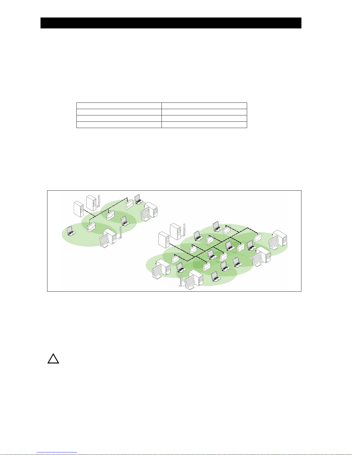
The HP WL520 provides wireless access to network infrastructures. As wireless clients move from one coverage cell to another,
HP WL520 units automatically allow client roaming within the same subnet. Figure 1-1 illustrates a typical network
configuration.
To determine the best location for the Base Station units, we recommend conducting a Site Survey before placing the devices in
their final locations. For information about how to conduct a Site Survey, contact your local reseller.
Before the HP WL520 unit can be configured for your specific networking requirements, it must first be initialized. Initialization
consists of setting a static IP address and the appropriate IP mask for the HP WL520 unit so that you can recognize it once it is
located in your network.
ng
t
e L520
WL520
WL520W
enterprise access point
enterprise access point enterprise access point
1
1
11
Figure 1-1
Figure 1-1 Standalone wireless network access infrastructure
gur
Figure 1-1Fi e 1-1
From there, the network administrator can configure each unit according to the requirements for the network. The HP WL520
Enterprise Access Point (HP WL520) functions as a wireless network access point to data networks. HP WL520 networks
provide:
To be fully operational, the HP WL520 needs at least one HP Wireless LAN PC Card.
Standalone wireless network access infrastructure
Standalone wireless network access infrastructure Standalone wireless network access infrastructure
Q Seamless client roaming
Q Easy installation and operation
Q Over-the-air encryption of data
Q High speed network links
1-1
Page 7

Manageme nt and Monitoring Capabilities
NOTE:
PC Cards are not included with your kit and must be ordered as separate items.
management and monitoring capabilities
management and monitoring capabilities
management and monitoring capabilitiesmanagement and monitoring capabilities
To configure the HP WL520 for your needs, set your specific network, wireless interface, and bridge parameters. The HTTP
(web browser) Interface provides easy configuration and management.
Wireless clients (computers connected to your network through a radio PC Card) use
access. Once connected, users can roam from one coverage cell to another while maintaining their connection.
There are three management and monitoring interfaces available to the network administrator to configure and manage the
HP WL520 device(s) in the network:
1. HTTP Interface
2. Command Line Interface
3. Full SNMP Configuration capabilities
http interface
http interface
http interfacehttp interface
The HTTP Interface (Web browser Interface) provides easy access to configuration settings and network statistics from any
computer in the network. Use the HTTP Interface through your LAN (switch, hub, etc.) through the Internet, or with a
"crossover" Ethernet cable connected directly to your computer’s Ethernet Port.
l
C ient Manager
software for network
command line interface
command line interface
command line interfacecommand line interface
The Command Line Interface (CLI) represents a set of keyboard commands and parameters used for configuring and
managing the HP WL520.
Users enter Command Statements, composed of CLI Commands and their associated parameters. Statements may be issued
from the keyboard for real time control, or from scripts that automate configuration.
download
For example, when downloading a file, administrators enter the
and file type parameters.
Q If necessary, use the CLI with your computer serial port to initialize the proper IP address for your network.
Q The CLI provides configuration and management access for most generic Telnet and Terminal clients. Use the CLI
through your computer serial port, over your LAN, through the Internet, or with a "crossover" Ethernet cable
connected directly to your computer.
Details of the CLI commands used to manage the HP WL520 device along with syntax and specific parameters names can be
found in
Using the Command Line Interface.
download CLI Command along with IP Address, file name,
downloaddownload
1-2
Page 8

802.11b vers us 802.11a Networks
802.11b versus 802.11a networks
802.11b versus 802.11a networks
802.11b versus 802.11a networks802.11b versus 802.11a networks
The HP WL520 supports 802.11wireless connectivity through the use of an 802.11a-compliant 5 GHz and 802.11bcompliant 2.4 GHz radio technology. The IEEE 802.11a standard adds support for a high-speed wireless physical layer in the
5 GHz band using Orthogonal Frequency Division Multiplexing (OFDM). The standard requires support for data rates of 6,
12, 24, and 54 Mbits/s. The HP WL520 unit supports the following data rates: 6, 9, 12, 18, 24, 36, 54 Mbits/s. The IEEE
802.11b standard supports wireless physical layer in the 2.4 GHz band using Direct Sequence Spread Spectrum (DSSS). The
standard provides for data rates of 1, 2, 5.5, and 11 Mbits/s.
feature list
feature list
feature listfeature list
The IEEE standards that governs wireless communications are different for the 2.4 GHz band and the 5 GHz band. The table
below compares the software features supported for each type of card in the HP WL520 device:
feature
feature
fe r
featureatu e
Number of stations per BSS up to 250 up to 50
HTTP Server yes yes
Telnet / CLI yes yes
SNMP Agent yes yes
VLAN Support (2 User VLANs) yes yes
Emergency Reset to Default Configuration yes yes
DHCP Client yes yes
DHCP Server yes yes
TFTP yes yes
RADIUS Access Control yes yes
802.1X (EAP-MD5, EAP-TLS and EAP-TTLS) yes yes
802.1d bridging yes yes
MAC Access Control Table yes yes
Protocol Filtering yes yes
Multicast/Broadcast Storm Filtering yes yes
Proxy ARP yes yes
Configuration Support for MAC Features yes yes
ICMP Echo Response yes yes
Hardware Watchdog Timer yes yes
Roaming yes yes
Link Integrity yes yes
Automatic Channel Select yes yes
WEP yes yes
WEP Plus (Weak Key Avoidance) yes No client support for 802.11a
WDS Relay yes
Remote Link Test yes
Link Test Responder yes No client support for 802.11a
Medium Density Distribution yes
Distance between AP's yes
Ultra High Density yes
Closed System yes
Interference Robustness yes
Load Balancing yes No client support for 802.11a
AP List yes No client support for 802.11a
SpectraLink VoIP Support yes
Fragmentation yes
2 hz
.4 g
2.4 ghz 5 gh5 ghz comments
2.4 ghz2.4
ghz
5 ghz5 ghz
z
comments
commentscomments
The HP WL520 device can be used with any combination of 802.11a and 802.11b radio cards. Note however, that only one
802.11a card with antenna adapter can be plugged into the HP WL520 unit at one time. You can have an 802.11a and an
802.11b card present in the HP WL520 device at the same time and 2.4 GHz and 5 GHz clients will be supported
simultaneously.
1-3
Page 9

802.11b vers us 802.11a Networks
cell size and coverage area
cell size and coverage area
cell size and coverage areacell size and coverage area
The coverage area achieved with the 2.4 GHz card type is larger than that of a 5 GHz radio card. The transmit rate is higher
in the smaller (2.4 GHz) cell than the larger (5 GHz cell). The following illustrations depict the difference in cell sizes and the
way that cell size affects coverage area.
Figure 1-2
Figure 1-2 802.11a (5 GHz) Cell Size
Figure 1-2Figure
Figure 1-3 802.11a versus 802.11b Coverage Area
Figure 1-3
Figure 1-3Figure
802.11a (5 GHz) Cell Size
1-2
802.11a (5 GHz) Cell Size 802.11a (5 GHz) Cell Size
802.11a versus 802.11b Coverage Area
1-3
802.11a versus 802.11b Coverage Area 802.11a versus 802.11b Coverage Area
1-4
Page 10

Installation and Initialization
auto channel select
auto channel select
auto channel selectauto channel select
The Access Point selects its own frequency channel, based on interference situation, bandwidth usage and adjacent channel
use, using the Auto Channel Select feature. This is beneficial when deploying HP WL520 units in a new environment or adding
an HP WL520 unit in an existing environment.
The default channel for the 5 GHz radio card is 52 - 5260 MHz. When a second HP WL520 unit is turned on in the vicinity of
the currently active HP WL520 device, the Auto Channel Select feature changes the frequency channel of the second unit so
there is no interference between the units. Multiple HP WL520 units can be turned on simultaneously to establish proper
channel selection.
Physical Layer Type
(Modulation Type)
Auto Channel Select Enable (default)
Frequency Channel 1 - 2.412 GHz
Distance Between APs Large (default)
Multicast Rate 1 Mbit/sec
Interference Robustness Enable (default)
Closed System Enable
Load Balancing Enable (default)
Medium Density Distribution Enable (default)
DSSS
(Direct Sequence Spread Spectrum)
Disable
2 - 2.417 GHz
3 - 2.422 GHz (default FCC, ETSI, Japan)
4 - 2.427 GHz
5 - 2.432 GHz
6 - 2.437 GHz
7 - 2.422 GHz
8 - 2.447 GHz
9 - 2.452 GHz
10 - 2.457 GHz
11 - 2.462 GHz
12 - 2.467 GHz (ETSI countries only)
13 - 2.472 GHz
14 - 2.477 GHz (Japan only)
For France, channels 10-13 only
Medium
Small
Minicell
Microcell
2 Mbits/sec
5.5 Mbits/sec (default)
11 Mbits/sec
Disable
Disable (default)
Disable
Disable
2.4 ghz
2.4 ghz
2.4 ghz2.4 ghz
(802.11b)
(802.11b)
(802.11b)(802.11b)
5 ghz
5 ghz
5 ghz5 ghz
(802.11a)
(802.11a)
(802.11a)(802.11a)
ODFM
(Orthogonal Frequency Division Multiplexing)
Enable (default)
Disable
36 - 5.180 GHz
40 - 5.200 GHz
44 - 5.220 GHz
48 - 5.240 GHz
52 - 5.260 GHz (default)
56 - 5.280 GHz
60 - 5.300 GHz
64 - 5.320 GHz
These channels are only valid in US/Canada,
and Japan at this time.
N/A
0 - Auto Fallback (default)
6 Mbit/sec
9 Mbits/sec
12 Mbits/sec
18 Mbits/sec
24 Mbits/sec
36 Mbits/sec
48 Mbits/sec
54 Mbits/sec
N/A
N/A
N/A
N/A
installation and initialization
installation and initialization
installation and initialization installation and initialization
The HP WL520 is designed to support both 2.4 GHz (IEEE 802.11b) radio cards and 5 GHz (IEEE 802.11a) radio cards. The
5 GHz card for the HP WL520 has an antenna adapter which snaps into place on the existing wall mounting bracket. Refer to
the printed Quick Start Guide provided in you kit for instructions on installing the Base Station hardware and initializing the
unit for your network.
1-5
Page 11

C
Conf ng the hp WL520 enterprise access point
CC
overview
overview
overviewoverview
in this chapter
in this chapter
in this chapterin this chapter
iguri
onfiguring the hp
onfiguring theonfiguring the hphp
Since each network is unique, the HP WL520 must be configured to operate in your network environment.
Most administrators use the HTTP Interface (web browser) for configuration; however, the Command Line Interface (CLI)
provides the same functionality by entering CLI Commands or scripts from Terminal and Telnet sessions. For information about
using the CLI, please refer to
In some scenarios described in this chapter, you need to make configuration choices (for example, which radio channel to use).
This guide explains each choice. When in doubt, we suggest you accept the default values.
Q Prerequisites
Q Set Basic Configuration Parameters
Q Download the latest software
– Setup your TFTP server
– Download updates to your TFTP server from the Web interface
– Backup your hp WL520 configuration file
– Copy a configuration file from another hp WL520 unit
Q Other Network Settings
– Configure the hp WL520 device as a DHCP Server
– Maintain 802.11b Client Connections using Link Integrity
Q Change your Wireless Interface Settings
– 802.11a Wireless Interface Card
– 802.11b Wireless Interface Card
– Auto Channel Select (ACS)
– Distance Between APs
– Multicast Rate
Q Ethernet Settings
– Set Ethernet Speed and Transmission Mode
Q Configure your Management Interfaces
– Set HTTP Interface Management Services
– Configure Serial Port Interface Settings
Q Other Security Configuration Settings
– Configure your MAC (Address) Access Control Table
– RADIUS Authentication Settings
– IEEE 802.1x Security Mode
Q If you encounter problems...
Using the Command Line Interface.
WL520
WL520WL520
enterprise access point
enterprise access pointenterprise access point
2
2
22
2-1
Page 12
Prerequisites
prerequisites
prerequisites
prerequisitesprerequisites
Before configuring the HP WL520, you need to gather certain network information. The following section identifies the
information you need. A form has been provided at the end of this guide for you to document the configuration settings of
each of the HP WL520 units in your network. Refer to Recording Your Configuration Settings.
Network Name (SSID of the wireless cards) Each wireless interface of your HP WL520 must be given a Network Name before users can sign on.
(HTTP) Password Each HP WL520 requires a read/write password to access the web interface. The default password is
Authentication Method A primary authentication server may be configured; a backup authentication server is also optional. The
Authentication Server Shared Secret This is a kind of password shared between the HP WL520 and the RADIUS authentication server (so both
Authentication Server Authentication Port This is a port number (default is 1812) and is typically provided by the network administrator.
Client IP Address Pool Allocation Scheme The HP WL520 can automatically provide IP addresses to clients as they sign on. The network
DNS Server IP Address The network administrator typically provides this IP Address.
This is not the same as the System Name, which applies only to the HP WL520 unit. This may apply to
the isolated unit, the immediate, active network, or to multiple networks. The network administrator
typically provides the Network Name(s).
"public".
network administrator typically provides this information.
passwords must be the same), and is typically provided by the network administrator.
administrator typically provides the IP Pool range.
NOTE:
Client Manager software comes with the PC Cards used in wireless client computers. The current network profile on
the wireless client must contain a valid Network Name; in other words, one of the case-sensitive Network Names
defined in the HP WL520 PC Card "Wireless Interface" properties. For more information, please refer to the PC Card
documentation.
set basic configuration parameters
set basic configuration parameters
set basic configuration parametersset basic configuration parameters
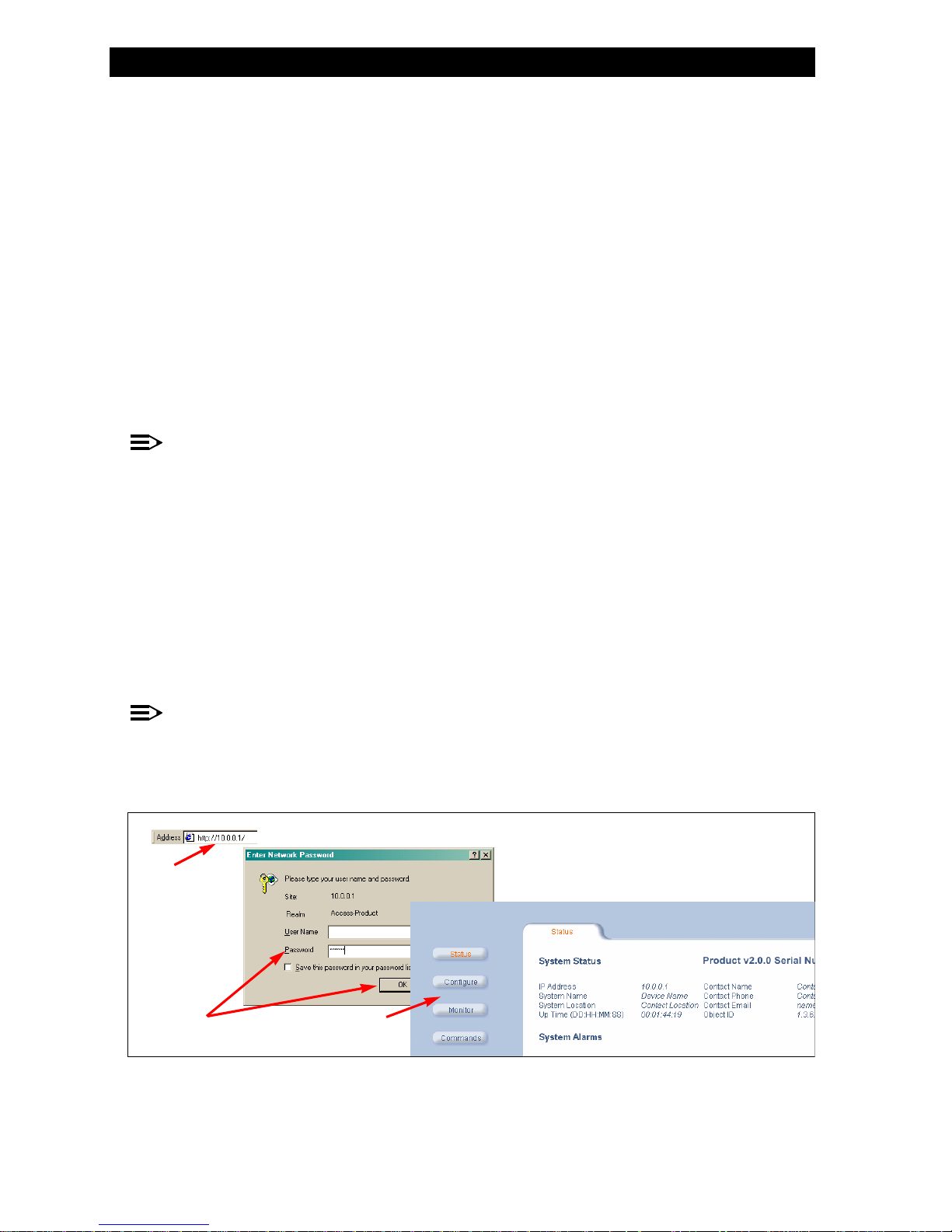
Once you have a valid IP Address assigned to your HP WL520 and an Ethernet connection, use your web browser to
configure the HP WL520 through the Web Interface.
log in to the
log in to the hphp WL520 unit using the web interface
log in to thelog in to the hphp
1. Ensure any proxies are turned off. Open your browser and enter the IP Address. Press ENTER. Result: The HP WL520
Login screen appears.
WL520
WL520WL520
unit using the web interface
unit using the web interface unit using the web interface
ENTER
ENTERENTER
NOTE:
Leave the User Name field empty
2. Enter public in the Password field. Result: The System Status screen appears.
3. Click the Configure operation button. Result: The System Configuration screen appears. Each tab contains information
for specific configuration categories.
1
Figure 2-1
Figure 2--1 Configuration through the Web Interface
gur
Figure 2-1Fi e 2 1
User Name
User NameUser Name
Password
PasswordPassword
Configure
ConfigureConfigure
2
Configuration through the Web Interface
Configuration through the Web Interface Configuration through the Web Interface
3
2-2
Page 13

Set Basic Configuration Parameters
You are now ready to configure each HP WL520 category, depending on your system. In some cases, you will not need to
make any changes. If you are in doubt about any setting, we recommend that you use the default values.
Figure 2-2
Figure 2-2 Configuration Options
Figure 2-2Figure 2-2
To set properties for each category, click on the desired tab. Result: The selected configuration screen appears. Each
configuration screen allows you to select options, or enter, edit, and delete information.
In some cases, the HP WL520 reminds you that it must be rebooted for a change to take effect. In a given session, you can
wait to reboot until all changes have been made.
After entering or editing information on configuration screens, click OK to save changes, or click CanceCancel to restore previous
settings.
You will want to set up a few basic configuration parameters right away when you receive the HP WL520 unit. For example:
– System name and location
– Contact information for network administrator
– IP Address
– Communication rules for your wireless interface(s)
– Passwords for the different management interfaces (SNMP, Telnet, HTTP)
– If you need to upload the latest software, you will also want to setup your TFTP server to communicate with the
Configuration Options
Configuration Options Configuration Options
OK
OKOK
HP WL520 device. This process is described in downloading the latest software, under
l
CancelCancel
Setup your TFTP server.
2-3
Page 14

set system name, location and contact information
set system name, location and contact information
set system name, location and contact informationset system name, location and contact information
Set Basic Configuration Parameters
Figure 2-3
Figure 2-3 System Configuration
Figure 2-3Figure 2-3
1. From the web interface, start by clicking on the Configure button, then the System tab.
2. Enter the name of the HP WL520 device, its location within your network or its physical location, such as “Front
set a static ip address for the
set a static ip address for the hp WL520 deevice
set a static ip address for the set a static ip address for the hphphp
1. Click on the Network tab and select the IP Address Assignment Type to Static.
2. Then enter a fixed IP Address for your HP WL520 unit, along with the IP mask and default gateway IP Address you
System Configuration
Sy io
System Configurationstem Configurat n
Configure
ConfigureConfigure
Lobby” or Engineering, the name, phone number and e-mail address of the person responsible for this device, and
OK
click OK.
OKOK
want to use.
Network
NetworkNetwork
WL520
WL520WL520
d vice
device device
IP Address Assignment Type
IP Address Assignment TypeIP Address Assignment Type
Static
StaticStatic
System
SystemSystem
NOTE:
The IP Mask of the HP WL520 unit needs to match the IP Mask of your network. If you are setting up the HP WL520
device from a client station, check the IP mask of your computer before proceeding.
3. Click OK when finished. The HP WL520 unit will need to be rebooted for the changes to take affect.
Figure 2-4
Figure 2-4 Neetwork IP Configuration
Figure 2-4Figure 2-4
Network IP Configuration
k IP io
Network IP Configuration N twor Configurat n
2-4
Page 15
Set Basic Configuration Parameters
set network names and encryption options
set network names and encryption options
set network names and encryption optionsset network names and encryption options
1. Select Network Names (SSID) for the PC Cards in wireless Slots A and/or B in the HP WL520 device. Client stations use
the Network Name of the PC Card to connect to the network through the HP WL520 unit.
At power up or insertion of either a 2.4 GHz or 5 GHz radio card, the HP WL520 software will automatically detect the
card type. The Configuration and Monitoring parameters displayed in the HTTP Interface will be updated accordingly. The
default values will be assigned.
Figure 2-5
Figure 2-5 Wireless Interface Configuration
r
Figure 2-5Figu e 2-5
The HP WL520 device can be used with any combination of 2.4 GHz (802.11b) and 5 GHz (802.11a) radio cards. Note
however, that only one 802.11a adapter card can be plugged into the HP WL520 unit at one time. You can have an
802.11a and an 802.11b card present in the HP WL520 device at the same time, and 2.4 GHz and 5 GHz clients will be
supported simultaneously.
Wirele f igu on
ss Inter ace Conf rati
Wireless Interface Configuration Wireless Interface Configuration
NOTE:
Not all software features available for the 802.11b cards are available for the 802.11a cards.
2-5
Page 16
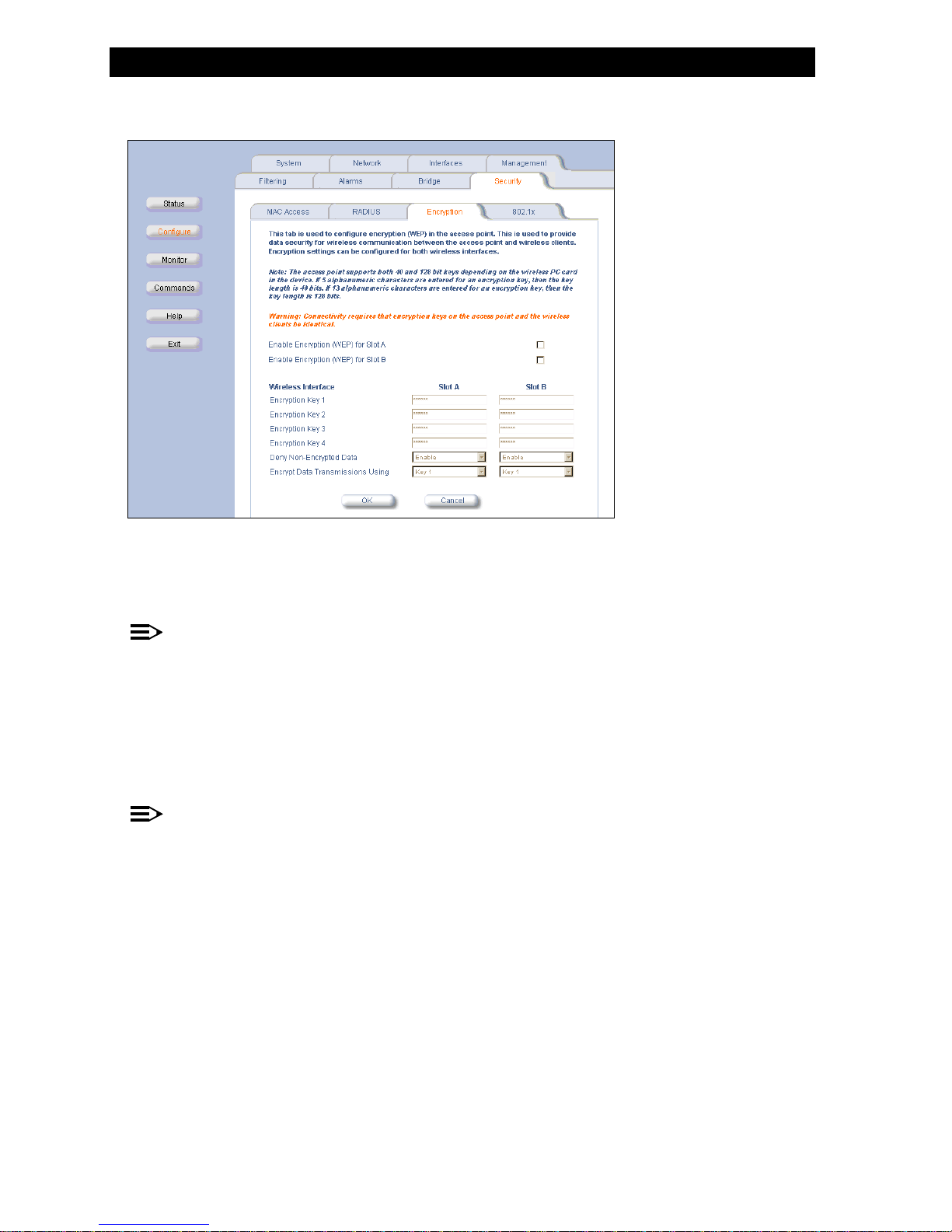
set wep encryption for each wireless interface
set wep encryption for each wireless interface
set wep encryption for each wireless interfaceset wep encryption for each wireless interface
Set Basic Configuration Parameters
Figure 2-6
Figure 2--6 WEP EncryptionEP Enc on
Figure 2-6Figure 2 6
1. Click on the Security > Encryption tabs.
2. Click inside the check box to
3. Type in an
W rypti
WEP Encryption WEP Encryption
Security > Encryption
Security > EncryptionSecurity > Encryption
enable WEP encryption on a wireless card.
enable WEP encryption
enable WEP encryptionenable WEP encryption
encryption key based on the type of card present in each slot.
encryption key
encryption keyencryption key
NOTE:
The HP WL520 device supports both 40- and 128-bit cards. 40-bit cards support key lengths of 5 alphanumeric
characters. 128-bit cards support key lengths of 13 alphanumeric characters.
4. Select which key to use for WEP encryption. Client stations must have the same encryption key to be able to
communicate with the HP WL520 device.
change passwords
change passwords
change passwordschange passwords
1. Click on the Management tab and change the default passwords for the SNMP, Telnet/CLI, and HTTP interfaces. The
default passwords for each interface is public.
Management
ManagementManagement
NOTE:
We strongly urge your to change the default passwords to restrict access to your network devices to authorized
personnel. We also recommend that you document your HP WL520 configuration using the work sheets provided for
you in Recording Your Configuration Settings. If you lose or forget your password settings, you can always perform
Reset to Factory Default procedure.
the
2-6
Page 17

Download the latest software
download the latest software
download the latest software
download the latest softwaredownload the latest software
There are three types of files that can be downloaded to the HP WL520 from a TFTP server:
— img (AP software image or kernel)
— config (configuration file)
— bspbl (BSP/Bootloader firmware file)
The latest updates on software and documentation can be found on the HP web site at:
setup your tftp server
setup your tftp server
setup your tftp serversetup your tftp server
The “Trivial File Transfer Protocol” (TFTP) server allows you to transfer files across a network. You can upload files from the
HP WL520 for backup or copying, and you can download the files for configuration and AP Image upgrades. The TFTP
software is located on the HP WL520 Installation CD-ROM.
If a TFTP server is not configured and running, you will not be able to download and upload images and configuration files
to/from the HP WL520. Remember that the TFTP server does not have to be local, so long as you have a valid TFTP IP
Address. TFTP does not have to be running for HP WL520 operations that do not transfer files.
After the TFTP server is installed:
Q Check to see that TFTP is configured to point to the directory containing the AP Image.
Q Make sure you have the proper TFTP server IP Address, the proper AP Image file name, and that the TFTP server is
connected.
0DNHVXUHWKH7)73VHUYHULVFRQILJXUHGWRERWK7UDQVPLWDQG5HFHLYHILOHVZLWKQRDXWRPDWLFVKXWGRZQRU
Q
0DNHVXUHWKH7)73VHUYHULLV
0DNHVXUHWKH7)73VHUYHULVFRQILJXUHGWRERWK7UDQVPLWDQG5HFHLYHILOHVZLWKQRDXWRPDWLFVKXWGRZQRU
PHRXW
WLPHRXW
WL
WLPHRXW
WLPHRXW
FRQILJXUHGWRERWK7UDQVPLWDQG5HFH YHI HVZLWKQRDXWRPDW FVKXWGRZQR
FRQILJXUHGWRERWK7UDQVPLWDQG5HFHLLYHILLOOHVZLWKQRDXWRPDWLLFVKXWGRZQRUU0DNHVXUHWKH7)73VHUYHU V
http://www.hp.com.
download updates to your tftp server from the web interface
download updates to your tftp server from the web interface
download updates to your tftp server from the web interfacedownload updates to your tftp server from the web interface
1. Make sure the TFTP server is running and pointing to the directory containing the desired file.
2. Open the web interface of the HP WL520 device.
3. Click on the
4. Type in the IP address of your TFTP server.
5. Type in the file name and select the file type from the pull down menu.
6. Click
Figure 2-7
Figure 2-7 Download Software Image from TFTP Server
Figure 2-7Figure 2-7
Commands
Commands button; select the Download tab.
CommandsCommands
OK
OK to download this information from the TFTP server to the HP WL520 unit.
OK OK
Download Software Image from TFTP Server
Download Software Image from TFTP Server Download Software Image from TFTP Server
Download
DownloadDownload
2-7
Page 18

Download the latest software
backup your
backup yourbackup yourhphphp
1. Make sure the TFTP server is running and pointing to the directory where you want to save the file.
2. Open the web interface of the HP WL520 device.
3. Click on the
4. Type in the IP address of your TFTP server.
5. Type in a descriptive name for your configuration file.
6. Select the file type as
7. Click OK to upload this information from your HP WL520 unit to the TFTP server, where it can be retrieved in the event
you reset your HP WL520 device to factory defaults at some time.
WL520
WL520 configuration filebackup your hp
WL52020
WL5
Commands
Commands button; select the Upload tab.
CommandsCommands
OK
OK OK
configuration file
configuration file configuration file
config from the pull down menu.
config
configconfig
Upload
UploadUpload
NOTE:
Record the name of this configuration file and the IP address of the HP WL520 unit so you can easily find it if you
need to download it.
copy a configuration file from another
copy a configuration file from another
copy a configuration file from another copy a configuration file from another hphp
You can configure multiple units using the same configuration file by uploading the configuration file from one HP WL520 unit
to the TFTP server, and then download the configuration file to other HP WL520 units.
WARNING:
!
o i ur o eDo not use a static IP address in this c nf g ati n l , otherwise you w l end up w th duplicate IP add e ses in your
network!
1. Check to ensure Dynamic IP address is enabled by clicking the Configure button and selecting the IPConfig tab. Then open
the Web interface from the HP WL520 unit with the desired configuration and click the
2. Select the
Upload tab and enter the IP address of your TFTP server.
Upload
UploadUpload
WL520
WL520WL520it unit unit
hp
unithp WL520 un
fi il i r s
Configure
ConfigureConfigure
Commands
Commands button.
CommandsCommands
Figure 2-8
Figure 2-8 Upload Configuration File to TFTP Server
gur
Figure 2-8Fi e 2-8
3. Enter the name of your configuration file and click
4. Wait for the file to transfer from the HP WL520 device to the TFTP server.
5. Access the HP WL520 unit to which you will download the configuration. A system window will notify you when this
process is complete. Confirm by clicking
6. Click on the Commands button, then select the Download tab.
7. Verify the IP address of your TFTP server and enter the name of the file you wish to transfer (refer to Step 3).
8. Set the file type to
9. The unit will need to be rebooted for the changes to take affect.
10. Repeat this procedure for all the HP WL520 units you want to configure using this specific file.
Upload Configuration File to TFTP Server
Upload Configuration File to TFTP Server Upload Configuration File to TFTP Server
Commands
CommandsCommands
config, and click OK. Click Download.
config
configconfig
OK
OKOK
OK.
OK
OKOK
OK
OK.
OKOK
Download
DownloadDownload
Download
DownloadDownload
2-8
Page 19

Other Networ k Settings
other network settings
other network settings
other network settingsother network settings
You may want to set other configuration parameters for your HP WL520 unit, such as:
– Configure the HP WL520 device as a DHCP server
– Maintain 802.11b client connections using Link Integrity checking
– Change your Wireless Interface settings
– Configure which physical interface will be used to manage the HP WL520 unit
– Control access to the HP WL520 device using MAC Address authentication, WEP encryption or 802.1x security settings
Refer to
Configuring Advanced Features for more complex network settings.
configure the
configure the hphp WL520 device as a dhcp server
configure theconfigure thehphp
Use DHCP configuration to provide dynamic client IP Addresses from one or more IP Pool Tables. Enable the DHCP Server to
allow the HP WL520 to assign clients IP Addresses from IP Pool Tables. Deselect the Status check box to prevent client IP
Address assignment from the HP WL520.
WL520
WL520WL520
device as a dhcp server
device as a dhcp server device as a dhcp server
NOTE:
You must have at least one entry in the DHCP Server client IP Address assignment table before you can enable the
DHCP Server Status feature.
Figure 2-9
Figure 2-9 Network Configuration Screens - DHCP Server
Figure 2-9Figure 2-9
1. From the HTTP interface, click on the
2. Click on the
3. Enter the following information:
Network Configuration Screens - DHCP Server
Network Configuration Screens - DHCP Server Network Configuration Screens - DHCP Server
Add button in the IP Pool Table.
Add
AddAdd
— Start IP AddressS t I
———tar P Address
Start IP AddressStart IP Address
—End I Add
End IP Addresss
—
—
—
— Default Lease Time (optional) - the default time value for clients to retain the assigned IP Address. DHCP
—
—
—
P re s
End IP AddressEnd IP Address
Default Lease Time
Default Lease TimeDefault Lease Time
automatically renews IP Addresses without client notification. Default is 86400 seconds.
Maximum Lease Time (optional) - the maximum time value for clients to retain the assigned IP Address. DHCP
Maximum Lease Time
Maximum Lease TimeMaximum Lease Time
automatically renews IP Addresses without client notification. Default is 86400 seconds.
Comment (optional)
Comment
CommentComment
Status - IP Pools are enabled upon entry in the table. Use the Edit button to disable or delete existing table entries.
Status
StatusStatus
Configure
Configure button and select the Network > DHCP Server tabs.
ConfigureConfigure
Network > DHCP Server
Network > DHCP ServerNetwork > DHCP Server
Edit
EditEdit
2-9
Page 20

Other Networ k Settings
4. Enter the Default Gateway IP Address, the Primary and Secondary DNS IP Addresses, and select the Enable DHCP Server
check box.
5. Reboot the HP WL520 unit for the changes to take affect.
maintain 802.11b client connections using link integrity
maintain 802.11b client connections using link integrity
maintain 802.11b client connections using link integritymaintain 802.11b client connections using link integrity
Default Gateway IP Address
Default Gateway IP AddressDefault Gateway IP Address
Primary
PrimaryPrimary
Secondary DNS IP Addresses
Secondary DNS IP AddressesSecondary DNS IP Addresses
Enable DHCP Server
Enable DHCP ServerEnable DHCP Server
NOTE:
This feature is only applicable to 2.4 GHz (802.11b) cards.
The Link Integrity feature checks the link between the HP WL520 and the nodes on the backbone. These nodes are listed by
their IP address on the Link Integrity IP Address Table, and serve as backup. If the link goes down, the client will connect to
another HP WL520 in your network that still communicates with the server.
Figure 2-10
Figure 2-10 Liink Integriitty
Figure 2-10Figure 2-10
configure link integrity
configure link integrity
configure link integrityconfigure link integrity
1. From the HTTP interface, click on the Configure button and select the Network > Link Integrity tabs.
2. Click the
3. Enter the IP Address of the host computer you want to check and add comments to identify the computer if you wish. This
Target IP Address is enabled as soon as it is entered in the table. Click
4. Set the following parameters as needed:
–
–
5. Click to select the
disable link integrity
disable link integrity
disable link integritydisable link integrity
Q To disable Link Integrity check for all clients, deselect the Enable Link Integrity check box.
Q To disable Link Integrity check to a certain host computer, click on the Edit button in the Tarrget IP Address Table and set the et I
Status
Status
StatusStatus
L nk Integr y
Link Integrity Link Integrity
Configure
ConfigureConfigure
Edit button in the Target IP Address Table.
Edit
EditEdit
Poll Interval - the interval between link integrity checks. Range is 500 - 15000 ms in increments of 500 ms; default is
Poll Interval
Poll IntervalPoll Interval
500 ms.
Poll Retransmissions - the number of times a poll should be retransmitted before the link is considered down.
Poll Retransmissions
Poll RetransmissionsPoll Retransmissions
Enable Link Integrity check box.
Enable Link Integrity
Enable Link IntegrityEnable Link Integrity
to Disable.
Target IP Address Table
Target IP Address TableTarget IP Address Table
Enable Link Integrity
Enable Link IntegrityEnable Link Integrity
Network > Link Integrity
Network > Link IntegrityNetwork > Link Integrity
OK.
OK
OKOK
Edit
EditEdit
TTTa g P Address Table
arget IP Address Tablearget IP Address Table
2-10
Page 21
Change your Wireless Interface Settings
change your wireless interface settings
change your wireless interface settings
change your wireless interface settingschange your wireless interface settings
Depending on the type of wireless PC Card installed in the HP WL520 device, the configuration options will be different. Some
parameters are the same for 802.11a and 802.11b cards. Others are unique to each card type.
You can setup an HP WL520 unit using the following combinations of wireless cards:
1. single 802.11a card with the attached antenna adapter
2. single 802.11b card
3. two 802.11b cards (one in each slot)
4. one 802.11a card with attached antenna and one 802.11b card
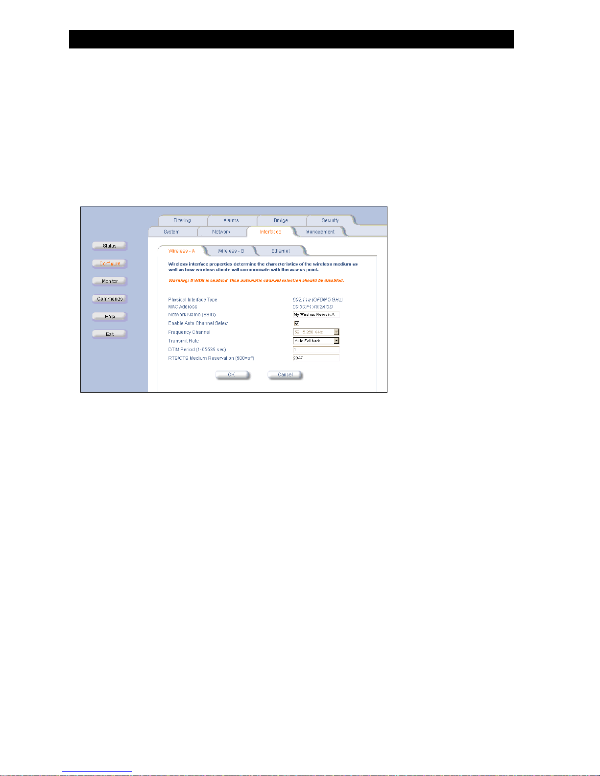
802.11a wireless interface card
802.11a wireless interface card
802.11a wireless interface card802.11a wireless interface card
Figure 2-11
Figure 2-11 802.11a Wireless Interface Options
Figure 2-11Figure 2-11
Network Name
– Network Name. Enter a Network Name for each PC Card. This is the same name used on client machines to connect using
Network NameNetwork Name
the Client Manager software.
Enable Auto Channel Select (ACS). By default this feature is enabled. The HP WL520 device will scan the area for other
Enable Auto Channel Select (ACS)
–
Enable Auto Channel Select (ACS)Enable Auto Channel Select (ACS)
HP WL520 devices and select a free or relatively unused communication channel. This helps prevent interference problems
and increases the performance of the network.
–
Frequency Channel. Use the pull-down menu to select the desired card frequency. Ensure nearby devices do not use the
Frequency Channel
Frequency ChannelFrequency Channel
same frequency. The Frequency Channels available will depend on the card type and the country of use. Refer to
Specifications for details.
– Transmit Rate. Use the pull-down menu to select a specific transmit rate for the 802.11a card. Choose between 6, 9, 12,
Transmit Rate
Transmit RateTransmit Rate
18, 24, 36, 48, 54 Mbits/s, or Auto Fallback. The Auto Fallback feature allows the HP WL520 unit to select the best
transmit rate based on the cell size.
–
DTIM Period. Deferred Traffic Indicator Map (DTIM) is used with clients that use power management. DTIM should be left at
DTIM Period
DTIM PeriodDTIM Period
the default value.
–
RTS/CTS Medium Reservation. This value affects message flow control, and should not be changed under normal
RTS/CTS Medium Reservation
RTS/CTS Medium ReservationRTS/CTS Medium Reservation
circumstances. Range is 2347 (on), 500 (off).
802.11a Wireless Interface Options
802.11a Wireless Interface Options 802.11a Wireless Interface Options
Radio
2-11
Page 22

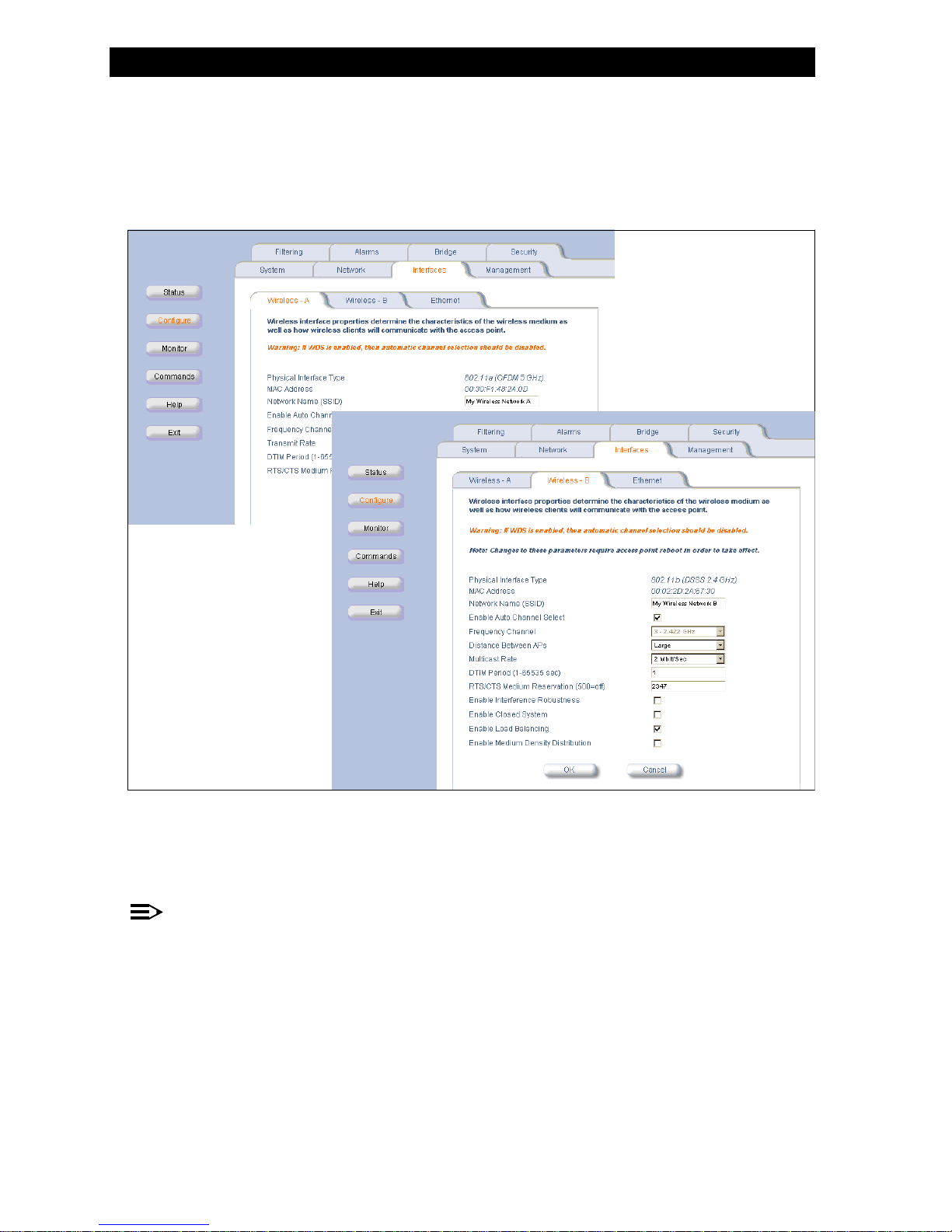
802.11b wireless interface card
802.11b wireless interface card
802.11b wireless interface card802.11b wireless interface card
Change your Wireless Interface Settings
Figure 2-12
Figure 2-12 802.11b Wireless Interface Options
Figure 2-12Figure 2-12
Network Name
– Network Name. Enter a Network Name for each PC Card. This is the same name used on client machines to connect using
Network NameNetwork Name
802.11b Wireless Interface Options
802.11b Wireless Interface Options 802.11b Wireless Interface Options
the Client Manager software.
–
Enable Auto Channel Select (ACS). By default this feature is enabled. The HP WL520 device will scan the area for other
Enable Auto Channel Select (ACS)
Enable Auto Channel Select (ACS)Enable Auto Channel Select (ACS)
HP WL520 devices and select a free or relatively unused communication channel. This helps prevent interference problems
and increases the performance of the network. However, if you are setting up a Wireless Distribution System (WDS), it
must be disabled.
–
Frequency Channel. Use the pull-down menu to select the desired card frequency. Ensure nearby devices do not use the
Frequency Channel
Frequency ChannelFrequency Channel
same frequency. The Frequency Channels available will depend on the card type and the country of use. Refer to
Radio
Specifications for details.
–
Distance between APs. Set to Large, Medium, Small, Microcell or Minicell depending on the site survey for your system. The
Distance between APs
Distance between APsDistance between APs
distance value is related to the
Large
Medium
LargeLarge
MediumMedium
Multicast Rate (described next). In general, larger systems operate at a slower average rate.
Multicast Rate
Multicast RateMulticast Rate
Small
SmallSmall
Microcell
MicrocellMicrocell
Minicell
MinicellMinicell
This feature is only available for 802.11b wireless cards.
–
Multicast Rate. Set the rate at which Multicast messages may be sent. This value is related to the Distance between APs
Multicast Rate
Multicast RateMulticast Rate
Distance between APs
Distance between APsDistance between APs
parameter (described previously). This feature is only available for 802.11b wireless cards.
distance between aps
distance between aps multi cast r at e
distance between apsdistance between aps
Large 1 and 2 Mbits/sec
Medium 1, 2, and 5.5 Mbits/sec
Small 1, 2, 5.5 and 11 Mbits/sec
Minicell 1, 2, 5.5 and 11 Mbits/sec
Microcell 1, 2, 5.5 and 11 Mbits/sec
multicast rate
multicast ratemulticast rate
2-12
Page 23

Change your Wireless Interface Settings
Enable Interference Robustness
– Enable Interference Robustness. Enable this option if other electrical devices in the 2.4 GHz range may be interfering with
Enable Interference RobustnessEnable Interference Robustness
the wireless signal. This feature is only available for 802.11b wireless cards.
–
Enable Closed System. Check this box to allow only clients configured with your specific Network Names to access the
Enable Closed System
Enable Closed SystemEnable Closed System
HP WL520. When disabled, a client configured with the Network Name “ANY” can connect to the HP WL520. This
feature is only available for 802.11b wireless cards.
Enable Load Balancing
– Enable Load Balancing. Enable this option so clients can evaluate which access point to associate with, based on current AP
Enable Load BalancingEnable Load Balancing
loads, to more evenly balance the load between APs. This feature is only available for systems using two 802.11b wireless
cards.
Enable Medium Density Distribution
–
Enable Medium Density Distribution. Enable this option to automatically notify client stations of roaming thresholds for the
Enable Medium Density DistributionEnable Medium Density Distribution
nearby APs. This feature is only available for 802.11b wireless cards.
auto channel select (acs)
auto channel select (acs)
auto channel select (acs)auto channel select (acs)
Auto Channel Select (ACS) tests available channels and selects one according to its signal strength. The channel range is set
by the regulatory agency responsible for your geographic region. Using a probe, the HP WL520 device scans appropriate
channels and selects the radio frequency channel with the best signal to noise ratio (i.e., signal strength). ACS is enabled by
default; however, if you plan to use WDS setup then you must disable ACS.
disabling acs
disabling acs
disabling acsdisabling acs
1. From the Web interface, select Configuration then click on the Interfaces tab.
2. Deselect the check box to disable Auto Channel Select.
3. Select a frequency channel from the drop-down menu. The clients automatically sense the channel and will configure
themselves to reassociate on the new channel.
Configuration
ConfigurationConfiguration
Interfaces
InterfacesInterfaces
WARNING:
!
s r il c l
enabling acs
enabling acs
enabling acsenabling acs
1. From the Web interface, select Configuration then click on the Interfaces tab.
2. Select the check box to
WARNING:
!
On changing the status you mu t eboot y u unit h c e t ro r , w i h w l disconnect all c i n s f om the HP WL520.
Configuration
ConfigurationConfiguration
Enable Auto Channel Select.
Enable Auto Channel Select
Enable Auto Channel SelectEnable Auto Channel Select
s r il l
Interfaces
InterfacesInterfaces
e t rOn changing the status you mu t eboot your unit, which w l disconne t a l cli n s f om the HP WL520.
2-13
Page 24
Change your Wireless Interface Settings
distance between aps
distance between aps
distance between apsdistance between aps
cells
cells
cellscells
The Distance between APs defines how far apart (physically) your HP WL520 devices are located, which in turn determines the
size of your cell. Cells of different sizes have different capacities and therefore suit different applications. For instance, a typical
office has many stations requiring high bandwidth and transmit rates for complex, high-speed data processing. In contrast, a
typical warehouse has a few forklifts requiring low bandwidth and transmit rates for simple transactions. Cell capacities are
compared in the following table, which shows small cells suit most offices, while large cells suit most warehouses:
small cell
small cell la lllarge cell
small cellsmall cell
Physically accommodates few stations Physically accommodates many stations
High cell bandwidth per station Lower cell bandwidth per station
High transmit rate Lower transmit rate
coverage
coverage
coveragecoverage
The number of access point units in a set area determines the network coverage for that area. A great number of access point
units covering a small area would be a high-density cell. Few access point units, or even a single unit covering the same small
area would result in a low-density cell, even though in both cases the actual area did not change- only the number of access
points covering the area changed.
In a typical office, smalls cells may have a ten foot (10’) diameter and an HP WL520 device every twenty feet (20’), which
would be considered high density. In contrast, large cells in a typical warehouse may have a ninety foot (90’) diameter and an
HP WL520 unit every two hundred feet (200’), considered low density.
rge ce
large celllarge cell
Figure 2-13
Figure 2-13Figure 2-13
set the distance between aps
set the distance between aps
set the distance between apsset the distance between aps
1. From the Web interface, click on the Configure button, select the Network > Interfaces tab.
2. Select the desired Wireless Slot tab.
3. Use the drop-down menu to set the
!
Lo y vs. U tra High De y Network
w Densit nsitFigure 2-13 Low Density vs. Ulltra High Density Network
Low Density vs. Ultra High Density NetworkLow Density vs. Ultra High Density Network
Wireless Slot
Wireless SlotWireless Slot
five values for the Distance between APs parameter (configurable for each Wireless NIC):
Large, Medium, Small, Minicell, and Microcell.
WARNING:
s
The Di tance between A s s ould not be appr x v y cP h o imated. It is calculated by means of a manual Site Sur e , in whi h
an HP WL520 unit is et up and c ien s a e te ted th o g t t e a ea to d te m i n l ength and co e a e n
local limits such as ph s c l inter er
s l t r s r str v
y i a f ence a e in estigated.
r rF om these measu ements the appropriate cell si e and density is determined, and the optimum Di tance between
AP e u ements.
s is calculated to suit your particular business r q ir
Configure
ConfigureConfigure
Multicast rate for the appropriate card.The HP WL520 recognizes the following
Multicast rate
Multicast rateMulticast rate
Network >
Network >Network >
Interfaces
InterfacesInterfaces
u hou h r e r ine s g a r g , a d
r v
z s
2-14
Page 25

Change your Wireless Interface Settings
multicast rate
multicast rate
multicast ratemulticast rate
The multicast rate measures how quickly information is transmitted across your network. This rate is approximated for a cell,
since physical proximity to the AP increases throughput. Stations closer to an AP actually have higher multicast rates than
stations in the same cell that are located farther from the AP. In addition, a small cell with several stations located close to the
access point can actually transmit information faster than a larger cell with only a few stations located farther from the
HP WL520 device.
11 Mbits/s
11 Mbits/s
11 Mbits/s11 Mbits/s
1 Mbit/s
1 Mbit/s
1 Mbit/s1 Mbit/s
Figure 2-14
Figure 2-14Figure 2-14
its/ Mb s Mu ca t Rates
1 Mb s and 11 its/ ltiFigure 2-14 1 Mbits/s and 11 Mbits/s Multicasst Rates
1 Mbits/s and 11 Mbits/s Multicast Rates 1 Mbits/s and 11 Mbits/s Multicast Rates
NOTE:
There is an inter-dependent relationship between the Distance between APs and the Multicast Rate. In general, larger
systems operate at a lower average transmit rate.The variation between Multicast Rate and Distance between APs is
presented in the following table:
1.0 mbit/s
1.0 mbit/s
1.0 mbit
1.0 mbit/s/s
Large yes yes
Medium yes yes yes
Small yes yes yes yes
Minicell yes yes yes yes
Microcell yes yes yes yes
set the multicast rate
set the multicast rate
set the multicast rateset the multicast rate
1. From the Web interface, click on the Configure button, and select the Network > Interfaces tabs.
2. Select the
Wireless - Slot A or Wireless - Slot B tab depending on where your 802.11b card is installed.
Wireless - Slot A or Wireless - Slot B
Wireless - Slot A or Wireless - Slot BWireless - Slot A or Wireless - Slot B
3. Use the drop down menu to select a Multicast rate.
2.0 mbits/s
2.0 mbits/s
0 mbit
2.0 mbits/s2. s/s
Configure
ConfigureConfigure
Multicast
MulticastMulticast
5.5 mbits/s
5.5 mbits/s
5 mb
5.5 mbits/s5. its/s
1 /s
1 mbits11 mbits/s
11 mbits/s11 mbits/s
Network > Interfaces
Network > InterfacesNetwork > Interfaces
NOTE:
The Distance between APs must be set before the Multicast Rate, because when you select the Distance between APs,
the appropriate range of Multicast values automatically populates the drop down menu.
must be set before
must be set beforemust be set before
2-15
Page 26

ethernet settings
ethernet settings
ethernet settingsethernet settings
set ethernet speed and transmission mode
set ethernet speed and transmission mode
set ethernet speed and transmission modeset ethernet speed and transmission mode
Ethernet Settings
Figure 2-15
Figure 2-15Figure 2-15
Configuration
Configuration. Select the desired speed and transmission mode from the pull down menu. Half-duplex means that only one
ConfigurationConfiguration
side can broadcast at a time, full-duplex allows both sides to transmit, while auto-duplex selects the best transmission mode for
the given configuration. The recommended setting is auto-speed-auto-duplex.
Choose between:
Q 10 Mbit/s - half duplex, full duplex, or auto duplex
Q 100 Mbit/s - half duplex, full duplex, or auto duplex
Q auto speed - half duplex
Q auto speed - auto duplex
configure your management interfaces
configure your management interfaces
configure your management interfacesconfigure your management interfaces
Select which interfaces will be available through the Wireless, Ethernet, and Serial Port interfaces of the HP WL520 unit.
rn te a e
Ethe et In rf cFigure 2-15 Ethernet Interface
Ethernet Interface Ethernet Interface
auto-speed-auto-duplex
auto-speed-auto-duplexauto-speed-auto-duplex
Figure 2-16
Figure 2-16 Management Interface Settings
gur
Figure 2-16Fi e 2-16
Management Interface Settings
Management Interface SettingsManagement Interface Settings
2-16
Page 27

Other Security Configuration Settings
set http interface management services
set http interface management services
set http interface management servicesset http interface management services
From the drop-down menu, select which physical interface(s) can be used to manage the HP WL520 device using the HTTP
management interface.
Choose between:
— Disabled (all interfaces)
— Ethernet only enabled
— Wireless A only enabled
— Wireless B only enabled
— All Interfaces enabled
Enter the HTTP communication port number. Default is 80.
configure serial port interface settings
configure serial port interface settings
configure serial port interface settingsconfigure serial port interface settings
The serial port interface on the HP WL520 device is enabled at all times. You can set the following parameters as needed:
Baud Rate
Baud Rate. Select the serial port speed (bits per second). Choose between 2400, 4800, 9600, 19200, 38400, or 57600;
–
Baud RateBaud Rate
9600.
the default Baud Rate is
– Flow Control. Select either None (default) or Xon/Xoff (software controlled) data flow control.
Flow Control
Flow ControlFlow Control
9600
96009600
None
NoneNone
Xon/Xoff
Xon/XoffXon/Xoff
NOTE:
To avoid unexpected performance of your HP WL520, leave the setting Flow Control to its default value (none) unless
you are sure what this setting should be.
other security configuration settings
other security configuration settings
other security configuration settingsother security configuration settings
Control access to the HP WL520 device using MAC Address authentication, WEP encryption, or 802.1x security settings
configure your mac (address) access control table
configure your mac (address) access control table
configure your mac (address) access control table configure your mac (address) access control table
The MAC Authentication tab allows you to build a list of stations, identified by their MAC addresses, authorized to access the
HP WL520 device within your network. The list is stored inside each HP WL520 within your network.
Figure 2-17
Figure 2-17 Security Configuration Screen - MAC AuthenticationSecu nfi ion Sc t tion
Figure 2-17Figure 2-17
Enable MAC Access Control
Enable MAC Access Control. Check this box to enable the Control Table.
–
Enable MAC Access ControlEnable MAC Access Control
Operation Type
– Operation Type. Choose between Passthru and Block. This determines how the stations identified in the MAC Access
Operation TypeOperation Type
Control Table are filtered.
rity Co gurat reen - MAC Au hentica
Security Configuration Screen - MAC Authentication Security Configuration Screen - MAC Authentication
Passthru
PassthruPassthru
Block
BlockBlock
2-17
Page 28

Other Security Configuration Settings
add an entry to the mac access control table
add an entry to the mac access control table
add an entry to the mac access control tableadd an entry to the mac access control table
OK
OK.
OKOK
Add
AddAdd
1. Click the Add button in the MAC Access Control table.
2. Enter the MAC Address of the client station authorized to manage this HP WL520 device.
3. Add a comment as needed. Entries are automatically enabled.
disable or delete an entry in the mac access control table
disable or delete an entry in the mac access control table
disable or delete an entry in the mac access control tabledisable or delete an entry in the mac access control table
1. Click the Edit button in the MAC Access Control Table.
2. Select the MAC Address you want to disable or delete.
3. Click
NOTE:
For larger networks that include multiple HP WL520 devices, you may prefer to maintain this list on a centralized
location using the
radius authentication settings
radius authentication settings
radius authentication settingsradius authentication settings
Also, if your network includes a RADIUS Server, you can use this tab to define the IP Address of the server that contains a
central list of MAC Address values that identify the authorized stations that may access the wireless network. You must specify
information for at least the Primary RADIUS server. The Backup RADIUS server is optional.
RADIUS Authentication Settings.
NOTE:
Problems with RADIUS Server configuration or RADIUS Authentication should be referred to the RADIUS Server
developer.
Enable RADIUS MAC Access Control Status
Enable RADIUS MAC Access Control Status. Click inside the check box to provide authentication by the RADIUS server.
–
Enable RADIUS MAC Access Control StatusEnable RADIUS MAC Access Control Status
Deselect the check box to prevent use of the RADIUS server.
Authorization Lifetime (seconds). Enter the time, in seconds, each client session may be active before being automatically re-
Authorization Lifetime (seconds)
–
Authorization Lifetime (seconds)Authorization Lifetime (seconds)
authenticated. Range is 900 - 43200 sec; default is 900 sec.
Enable the Primary or Backup RADIUS Server
Enable the Primary or Backup RADIUS Server. Click in the desired check box to enable the RADIUS Server.
–
Enable the Primary or Backup RADIUS ServerEnable the Primary or Backup RADIUS Server
–
IP Address.
IP Address
IP AddressIP Address
– Destination Port.
Destination Port
Destination PortDestination Port
–
Shared Secret. The password for the user on the RADIUS Server must be the same as the Shared Secret.
Shared Secret
Shared SecretShared Secret
–
Response time (seconds).
Response time (seconds)
Response time (seconds)Response time (seconds)
–
Maximum Retransmissions.
Maximum Retransmissions
Maximum RetransmissionsMaximum Retransmissions
Figure 2-18
Figure 2-18 Security Configuration Screen - RADIUS Authentication
gur
Figure 2-18Fi e 2-18
Security Configuration Screen - RADIUS Authentication
Security Configuration Screen - RADIUS Authentication Security Configuration Screen - RADIUS Authentication
2-18
Page 29

Other Security Configuration Settings
IEEE
802.1x security mode
IEEE 802.1x security mode
IEEEIEEE
802.1x security mode 802.1x security mode
IEEE 802.1x is a proposed standard that provides a means to authenticate and authorize network devices attached to a LAN
port. A port in the context of IEEE 802.1x is a point of attachment to the LAN, either a LAN jack for the case of a desktop PC,
or a laptop PC association with an Access Point device.
authentication process
authentication process
authentication processauthentication process
There are three main components in the authentication process. The standard refers to them as:
1. supplicant (client PC)
2. authenticator (Access Point)
3. authentication server (RADIUS server)
When using 802.1x Security Mode or Mixed mode (802.1x and WEP), you need to configure your Radius server for
authentication purposes.
Initially the unauthenticated client PC cannot send any data traffic through the HP WL520 device to other systems on the LAN.
Data traffic is always encrypted with a WEP key that the client PC receives after it has been authenticated. The HP WL520
device inhibits all data traffic from a particular client PC until the client PC is authenticated. Regardless of its authentication
status, a client PC can always exchange 802.1x messages in the clear with the HP WL520 unit.
The HP WL520 device acts as a pass-through device to facilitate communications between the client PC and the RADIUS
server. The HP WL520 unit and the client PC exchange 802.1x messages using an EAPOL protocol. Messages sent from the
client station are encapsulated by the HP WL520 device and transmitted to the RADIUS server using EAP extensions.
Upon receiving a reply EAP packet from the RADIUS, the message is typically forwarded to the client PC, after translating it
back to the EAPOL format. Negotiations take place between the client PC and the RADIUS server. In case of success, the
RADIUS server sends a per-session key to the HP WL520 device.
NOTE:
Currently, only the EAP type of EAP-TLS (smart card or certificate) is supported when using 802.1x security mode
only. In mixed mode, both the EAP-TLS and EAP-MD5 types are supported provided that the RADIUS server is also
configured to support both types.
Operating System MD5 TLS TTLS
Windows 98
Windows 98SE
Windows ME
Windows 2000
Windows XP
Click on the Encryption tab in the
to set the over-the-air encryption properties for each wireless card. In this procedure, “Slot A” refers to PC Card A, and “Slot B”
refers to PC Card B.
9 9 8
9 9 8
9 9 8
9 9 9
9 9 9
Security Configuration screen to set the 802.1x security mode for the HP WL520 and/or
2-19
Page 30

Other Security Configuration Settings
The HP WL520 software offers several methods for configuring security settings:
1RVHFXULW\RUHQFU\SWLRQ
1RVVHFXULLWW\\RUUHQFU\SWLRQ
1.
1RVHFXULW\RUHQFU\SWLRQ
1R HFXU R HQFU\SWLRQ
Set the 802.1x Security Mode to none and make sure the Encryption status is set to disable for both wireless interface
cards.
2.
:(3HQFU\SWLRQRQO\RQRQHRUERWKZLUHOHVVLQWHUIDFHV
:(3HQFU\\SWLRQRQO\RQRQHRUERWKZLUHOHVVVLQWHUIIDFHV
:(3HQFU\SWLRQRQO\RQRQHRUERWKZLUHOHVVLQWHUIDFHV
:(3HQFU SWLRQRQO\RQRQHRU ERWK ZLUHOHV LQWHU DFHV
WEP encryption is the wireless equivalent of the security level available through a wired network. Select the 802.1x
Security Mode to
Depending on the card type, the Encryption Key Length will be 40- or 128-bits. This will determine the number of
characters allowed for each the Encryption Key. Select the encryption key length from the drop-down menu.
You can specify up to four encryption keys between 5 and 12 alphanumeric characters depending on the key length
supported by the PC Card in each slot. However, you will only use one key to encrypt data to be transmitted.
[VHFXULW\UHTXLUHV5$',86VHUYHUDXWKHQWLFDWLRQ
3.
[VHFXULWLW\UHTXLUHV5$',86VHUYHUUDXWKHQWLFDWWLLRQ
[VHFXULW\UHTXLUHV5$',86VHUYHUDXWKHQWLFDWLRQ
[VHFXU \UHTXLUHV 5$',86VHUYH DXWKHQWLFD RQ
When you decide to use the 802.1x security mode, you must first configure the RADIUS server to receive an
authentication response. Your computer operating system must also be configured to receive and send authenticated
packets.
4.
0L[HGPRGHZLWK[DQG:(3HQFU\SWLRQ
0L[HGPRGHZLWK[DQG:(3HQFU\\SWLRQ
0L[HGPRGHZLWK[DQG:(3HQFU\SWLRQ
0L[HG PRGHZLWK[DQG:(3HQFU SWLRQ
With 802.1x security mode, an Encryption Key entry is not required, since this mode creates keys dynamically. In
Mixed mode, Encryption Keys 2-4 are not required.
5.
0L[HGPRGHDQG[5HNH\,QWHUYDO
0L[HGPRGHDQG[5HNH\,QWHUYDO
0L[HGPRGHDQG[5HNH\,QWHUYDO
The rekey feature determines how often your encryption key is changed (the interval between changes) and can be set
to any value between 60 - 65535 seconds. Compared with re-authentication, rekeying frustrates hacking attempts
without taxing system resources. Setting a fairly frequent rekey value (900 seconds=15 minutes) effectively protects
against intrusion without disrupting network activities.
none
none and enable the Encryption status for one or both wireless PC Cards.
nonenone
enable
enableenable
none
nonenone
O0L[HGPRGHDQG[5HNH\,QWHUYD
disable
disabledisable
setting up the
setting up the hp WL520 using 802.1x security mode
setting up thesetting up thehphphp
1. From the Web interface, select Security, then click on the Encryption tab.
2. Set the 802.1x Security Mode to 802.1x and click OK. Ignore the reboot message - this can be done when the entire
procedure is finished.
3. Select the RADIUS Authentication tab.
4. Enter the RADIUS server password in the Shared Secret and Confirm Shared Secret fields.
5. Enable the Primary RADIUS server.
6. Enter the IP Address for the Primary RADIUS server.
7. Enter the Destination Port. The default is 1812, however your RADIUS server provider may have another
communication port defined.
8. Define the Response Time and Response Maximum Retransmission values.
9. Reboot the HP WL520 device for these changes to take affect.
WL520
WL520WL520
using 802.1x security mode
using 802.1x security mode using 802.1x security mode
Figure 2-19
Figure 2-19 Security Configuration Screen - 802.1x Security ModeSec nf n S Sec
Figure 2-19Figure 2-19
urity Co iguratio creen - 802.1x urity Mode
Security Configuration Screen - 802.1x Security Mode Security Configuration Screen - 802.1x Security Mode
2-20
Page 31

If you encounter problems...
802.1x security and wireless distribution systems
802.1x security and wireless distribution systems
802.1x security and wireless distribution systems802.1x security and wireless distribution systems
Wireless distribution systems are setup using specific ports on the HP WL520 unit and frequency channels in the wireless
interface cards. To use 802.1x with WDS, you need to set the 802.1x Security Mode to Mixed (WEP and 802.1x), to make
sure that the HP WL520 and the clients share the same encryption key (Key 1).
IT managers can install HP WL520 access points with Wi-Fi radios and gradually migrate to the 802.11a radios without
replacing their access points or client devices. As 802.11a radios become available, they can simply pop out one of the Wi-Fi
radios from one of the dual slots and replace it with an 802.11a radio.
if you encounter problems...
if you encounter problems...
if you encounter problems...if you encounter problems...
Q Cannot Associate with a Network. When the Client Manager starts, it automatically looks for a network. If it cannot
associate with a network, you will see a message reminding you to update the case-sensitive Network Name in the current
Client Manager Configuration Profile.
NOTE:
Ask your network administrator for the correct Network Name, and then edit the profile by opening Client Manager.
Select
Actions -> Add/Edit Configuration Profile -> Edit Profile -> Basic
Actions -> Add/Edit Configuration Profile -> Edit Profile -> Basic. Enter the Network Name and then click OK.K
Actions -> Add/Edit Configuration Profile -> Edit Profile -> BasicActions -> Add/Edit Configuration Profile -> Edit Profile -> Basic
For more information, please refer to your PC Card documentation.
Q If the Network Name is the same in both the client and the HP WL520 device, then verify the settings in the Security
Properties table, which includes encryption settings.
Q Other Errors. Systematically double-check the HP WL520 unit settings, especially the IP Addresses and the client IP
Address Pool.
For more information, please refer to Troubleshooting in this guide.
O
OKOK
2-21
Page 32

MMMnagi
Ma ng the
anaging the hp WL520 enterprise access point
anaging the anaging the hphphp
in this chapter
in this chapter
in this chapterin this chapter
Q Management Interface
Q Monitoring Network Statistics
– View Hardware/Software Component Information
– Monitoring ICMP Statistics
– Monitoring IP/ARP Statistics
– Monitoring Learn Table Statistics
– Monitoring IAPP Statistics
– Monitoring RADIUS Server Statistics
– Monitoring Interfaces Statistics
– Monitoring Remote Link Test Statistics
Q Issuing System Commands
– Download
– Upload
– Reboot
– Reset
– Help link
WL520
WL520W
L520
enterprise access point
enterprise access point enterprise access point
3
3
33
3-1
Page 33

Management Interface
management interface
management interface
management interfacemanagement interface
Once you have a valid HP WL520 IP Address and an Ethernet connection, you may use your web browser to issue commands
and monitor network statistics.
The Command Line Interface (CLI) also provides a method for issuing commands and viewing network statistics using Telnet
and Terminal clients. This section covers only use of the HTTP Interface. For more information about issuing commands and
viewing network statistics with the CLI, refer to Using the Command Line Interface.
1
2
Figure 3-1
Figure 3-1 Login to HTTP Interface
Figure 3-1Figure
1. Open your browser and enter the IP Address in the address bar. Press the
appears.
Login to HTTP Interface
3-1
Login to HTTP Interface Login to HTTP Interface
ENTER
ENTER key. Result: The HP WL520 Login screen
ENTERENTER
NOTE:
Leave the User Name field empty
2. Enter your password in the Password field (default is “public”).
3. Each section of the
System Status
– System Status. This area provides system level information, including the HP WL520 IP Address and contact
System StatusSystem Status
information.
–
System Traps
System Traps. System traps (if any) appear in this area. Each trap identifies a specific severity level.
System TrapsSystem Traps
User Name
User NameUser Name
Password
PasswordPassword
System Status screen provides the following information.
3-2
Page 34

Monitoring Network Statistics
monitoring network statistics
monitoring network statistics
monitoring network statisticsmonitoring network statistics
To observe the HP WL520 network statistics, click the Monitor button. Result: The Monitor screen appears. Each tab contains
information for monitoring specific statistics.
Monitor
MonitorMonitor
Figure 3-2
Figure 3-2 Monitor Screen
r
Figure 3-2Figu e 3-2
view hardware/software component information
view hardware/software component information
view hardware/software component informationview hardware/software component information
Figure 3-3
Figure 3-3 Hardware/Software Component Information
r
Figure 3-3Figu e 3-3
From the HTTP interface, click on the Monitor button and select the Version tab. The list displayed provides you with information
that may be pertinent when calling Technical Support. With this information, your Technical Support representative can verify
compatibility issues and make sure the latest software and drivers are loaded.
M nitor Screen
o
Monitor Screen Monitor Screen
H rdware oftware Component rmation
a /S Info
Hardware/Software Component Information Hardware/Software Component Information
Monitor
MonitorMonitor
Version
VersionVersion
3-3
Page 35

Monitoring Network Statistics
monitoring icmp statistics
monitoring icmp statistics
monitoring icmp statisticsmonitoring icmp statistics
This tab provides message related information for both received and transmitted messages directed to the HP WL520 device.
Not all network traffic is counted in ICMP statistics.
monitoring ip/arp statistics
monitoring ip/arp statistics
monitoring ip/arp statisticsmonitoring ip/arp statistics
This tab provides information based on the Address Resolution Protocol (ARP), which relates MAC Address and IP Addresses.
monitoring learn table statistics
monitoring learn table statistics
monitoring learn table statisticsmonitoring learn table statistics
This tab displays information relating to network bridging, specifically, the MAC Address and interface number. There can be
up 2000 entries in the Learn Table.
3-4
Page 36

Monitoring Network Statistics
monitoring iapp statistics
monitoring iapp statistics
monitoring iapp statisticsmonitoring iapp statistics
This tab displays statistics relating to client handovers and communications between Access Points.
monitoring radius server statistics
monitoring radius server statistics
monitoring radius server statisticsmonitoring radius server statistics
This tab provides RADIUS authentication information for both the Primary and Backup RADIUS servers.
NOTE:
RADIUS authentication must be enabled for this information to be valid.
3-5
Page 37

Monitoring Network Statistics
monitoring interfaces statistics
monitoring interfaces statistics
monitoring interfaces statisticsmonitoring interfaces statistics
This tab displays information for the Ethernet interface, as well as each PC Card interface. The Operational Status can be: 1 =
up, 2 = down, 3 = testing.
monitoring remote link test statistics
monitoring remote link test statistics
monitoring remote link test statisticsmonitoring remote link test statistics
This tab displays information on the quality of the wireless link to clients and other HP WL520 units in the Wireless Distribution
System.
NOTE:
The Remote Link Test feature is only available for 2.4 GHz (802.11b) clients.
3-6
Page 38

Issuing System Commands
To find wireless clients connected to the HP WL520 device, click Explore, then the Refresh button. To test the link quality, select
a station, and then click
Ratio (SNR).
issuing system commands
issuing system commands
issuing system commandsissuing system commands
To issue commands, click on the Commands operation button. Result: The Commands screen appears. Each tab allows a
specific operation.
Link Test
Link Test. Quality is measured in terms of Signal strength, Noise strength, and the Signal to Noise
Link TestLink Test
Commands
CommandsCommands
Explore
ExploreExplore
Refresh
RefreshRefresh
3-7
Page 39

download
download
downloaddownload
Issuing System Commands
Figure 3-4
Figure 3-4 Commands Screen - Download
gur
Figure 3-4Fi e 3-4
Use the Download tab to download Configuration, AP Image, and Bootloader files to the HP WL520. A TFTP server must be
Commands Screen - Download
Commands Screen - Download Commands Screen - Download
Download
DownloadDownload
running and configured to point to the directory containing the file.
If you don’t have a TFTP server installed on your system, install the TFTP server from the CD. Select the “Xtras/TFTP” sub-
directory, double-click “OEM-TFTP-Server.exe”, and follow the directions given to complete the installation.
The
Download
Download tab shows version information and allows you to enter TFTP information as described below.
DownloadDownload
Server IP Address
Server IP Address. Enter the TFTP server IP Address.
–
Server IP AddressServer IP Address
Double-click on the TFTP server icon on your desktop and locate the IP address assigned to the TFTP server. Note: This is
the IP address that will be used to point the Access Point to the AP Image file.
–
File Name
File Name. Enter the name of the file to be downloaded.
File NameFile Name
Copy the updated AP Image file to the shared TFTP server folder. The default AP Image is located at
C:/Program Files/HP/WL520_AP/.
–
File Type. Select the proper file type. Choices include:
File Type
File TypeFile Type
–
Config for configuration information, such as System Name, Contact Name, and so on.
Config
ConfigConfig
– Img for the AP Image (executable program).
Img
ImgImg
–
BspBl for the Bootloader software.
BspBl
BspBlBspBl
–
File Operation. Select either Download, or Download & Reboot. You should reboot the HP WL520 after downloading files.
File Operation
File OperationFile Operation
Download
DownloadDownload
Download & Reboot
Download & RebootDownload & Reboot
3-8
Page 40

Issuing System Commands
upload
upload
uploadupload
Upload
Use the Upload tab to upload Configuration files from the HP WL520. The TFTP server must be running, and configured to
UploadUpload
point to the directory that is to contain the uploaded file. We suggest you assign the file a meaningful name, which may
include version or location information.
If you don’t have a TFTP server installed on your system, install the TFTP server from the CD. Select the“Xtras/TFTP” subdirectory, double-click “OEM-TFTP-Server.exe”, and follow the directions given to complete the installation.
–
Server IP Address. Enter the TFTP server IP Address.
Server IP Address
Server IP AddressServer IP Address
Double-click on the TFTP server icon on your desktop and locate the IP address assigned to the TFTP server. Note: This is
the IP address that will be used to point the Access Point to the AP Image file.
File Name
– File Name. Enter the name of the file to be uploaded.
File NameFile Name
Copy the updated AP Image file to the shared TFTP server folder. The default AP Image is located at
C:/Program Files/HP\WL520_AP/.
–
File Type. Select Config.
File Type
File TypeFile Type
–
File Operation. Select Upload.
File Operation
File OperationFile Operation
Config
ConfigConfig
Upload
UploadUpload
reboot
reboot
rebootreboot
Reboot
Use the Reboot tab to save configuration changes (if any) and reset the HP WL520. Entering a value of 0 (zero) seconds
RebootReboot
causes an immediate reboot.
Note that
Reset
Reset, covered below, does not save configuration changes.
ResetReset
3-9
Page 41

reset
reset
resetreset
Issuing System Commands
Reset
Use the Reset tab to restore the HP WL520 to factory default conditions. The HP WL520 may also be reset from the RESET
ResetReset
button on indicator side of the unit. Since this will reset the current HP WL520 IP Address, a new IP Address must be assigned.
Also refer to
help link
help link
help linkhelp link
To open the Help Link, click the Help button on any display screen.
During initialization, the WL520 on-line help files are downloaded to the default location:
C:/Program Files/HP/WL520_AP/Help/.
If you want to place these files on a shared drive, copy the Help Folder to the new location, and then specify the new path in
the Help Link box.
Recovery Procedures.
C:/Program File s/H P/WL520_AP/Help/inde x.htm
Help Link
Help LinkHelp Link
Help
HelpHelp
RESET
RESETRESET
3-10
Page 42

CCCo i i dvanced features
onfiguring advanced features
C nf gur ng a
onfiguring advanced featuresonfiguring advanced features
in this chapter
in this chapter
in this chapterin this chapter
Some of the more complex networking configurations are described in this chapter:
4
4
44
Network Settings
• Advanced DHCP Server Configuration
• DHCP IP Pool Table Settings
• Link Integrity Settings
VLAN Support
• Typical VLAN configurations
• VLAN Workgroups and Traffic Management
• Typical User VLAN Configurations
• Typical VLAN Management ID Configuration Scenarios
Management Settings
• Setting new Passwords
• Managing IP Access
• Configuring Management Service Interfaces
Setting Filters
• Setting the Ethernet Protocol Filter
• Advanced Filtering
Alarms (SNMP Traps)
• Alarm (Trap) Groups
• Alarm Host Table
Bridge Configuration Settings
• Spanning Tree Protocol
• Broadcast Storms and Storm Thresholds
Wireless Distribution System (WDS)
WDS Setup Procedure
•
• Wireless Port Mapping
Set parameters for DHCP server including the IP Pool table. Configure Link
Integrity settings and Target IP Address table.
Setup a VLAN network.
Configure system management settings such as passwords, management IP
Access table, and services’ parameters (SNMP, Telnet, HTTP, Serial).
Set HP WL520 device filters including Ethernet filters, Static MAC address
filters, and other advanced filters.
Set alarms (SNMP Traps) including enabling alarm groups and the alarm
host table.
Setup the HP WL520 device as a simple bridge or a wireless repeater,
setup loop avoidance through the Spanning Tree protocol and Storm
Threshold protection.
Establish point-to-point connections with other access points (the wireless
backbone).
Advanced Security Settings
• Wireless Security - EAP Overview
• MAC Access
• RADIUS Authentication Tab
Configure advanced security settings including MAC access control,
RADIUS MAC access control, RADIUS servers, and 802.1x parameters.
4-1
Page 43

Network Settings
network settings
network settings
network settingsnetwork settings
advanced dhcp server configuration
advanced dhcp server configuration
advanced dhcp server configurationadvanced dhcp server configuration
Configure DHCP to provide dynamic client IP Addresses from one or more IP Pool Tables. Create IP Pool Tables by specifying
a Start IP Address and an End IP Address.
–
DHCP Server Status
DHCP Server Status. Select Enable to allow the HP WL520 to assign clients IP Addresses from IP Pool Tables. Select DisablDisable
DHCP Server StatusDHCP Server Status
to prevent client IP Address assignment from the HP WL520.
Enable
EnableEnable
NOTE:
You must have at least one entry in the DHCP Server IP Address Pool table before you can enable the DHCP Server
feature.
IP Mask
IP Mask. Read-only value of the HP WL520 mask.
–
IP MaskIP Mask
– Gateway IP Address. Enter the default Gateway IP Address.
Gateway IP Address
Gateway IP AddressGateway IP Address
–
Primary DNS IP Address. Enter the Domain Name Server IP Address.
Primary DNS IP Address
Primary DNS IP AddressPrimary DNS IP Address
–
Secondary DNS IP Address. Enter the Domain Name Server IP Address.
Secondary DNS IP Address
Secondary DNS IP AddressSecondary DNS IP Address
dhcp ip pool table settings
dhcp ip pool table settings
dhcp ip pool table settingsdhcp ip pool table settings
To add an entry, click Add, and then specify the start and end IP Address.
Start IP Address. Enter the starting IP Address for this IP Pool Table.
–
Start IP Address
Start IP AddressStart IP Address
–
End IP Address. Enter the ending IP Address for this IP Pool Table.
End IP Address
End IP AddressEnd IP Address
Comment. Enter related information.
–
Comment
CommentComment
–
Status. Shows enabled/disabled status.
Status
StatusStatus
To edit or delete an entry, click Edit. Edit the information, or select Enable, Disable, or Delete from the Status pull-down menu.
Add
AddAdd
Edit
EditEdit
Enable
EnableEnable
Disable
i able
DisableD s
Delete
DeleteDelete
DisableDisable
e
4-2
Page 44

Network Settings
link integrity settings
link integrity settings
link integrity settingslink integrity settings
This feature checks the link between the HP WL520 and connected network server(s). If the link goes down then the client will
connect to another HP WL520 in your network that still communicates with the server.
–
Link Integrity Status
Link Integrity Status. Select Enable to activate the Link Integrity feature.
Link Integrity StatusLink Integrity Status
–
Poll Interval. Set the interval (minimum 500ms and in increments of 500ms) between polls.
Poll Interval
Poll IntervalPoll Interval
– Poll Retransmissions. Set the number of times a poll should be retransmitted before the link is considered down.
Poll Retransmissions
Poll Retr ssi
Poll Retransmissionsansmi ons
target ip address table settings
target ip address table settings
target ip address table settingstarget ip address table settings
To add an Target IP Address entry, click Add, and then specify the IP Address of the servers you want to check.
Target IP Address
Target IP Address. Enter the IP Address
–
Target IP AddressTarget IP Address
Comments
– Comments. Enter related information.
CommentsComments
Status
–
Status. Shows enabled/disabled status. A disabled status only means that the HP WL520 is not checking the link, for
StatusStatus
example, when the network server is being serviced.
To edit or delete an entry, click
Enable
EnableEnable
Add
AddAdd
Edit
Edit. Edit the information, or select Enable, Disable, or Delete from the Status pull-down menu.
EditEdit
Enable
EnableEnable
Disable
DisableD s
i able
Delete
DeleteDelete
4-3
Page 45

VLAN Support
vlan support
vlan support
vlan supportvlan support
Virtual Local Area Networks (VLANs) are logical groupings of network resources. Defined by software settings, VLAN
resources appear (to clients) to be in the same room, no matter where they are attached on the physical LAN segment. They
simplify traffic flow between clients and their frequently-used or restricted resources.
VLANs now extend as far as the access point signal reaches; clients can connect from anywhere in the broadcast area. The
broadcast area is defined by the network name configured for the wireless card on the access point device.
HP WL520 devices are fully VLAN-ready; however, by default VLAN support is disabled. Before enabling VLAN support,
certain network settings should be configured, and network resources such as a VLAN-aware switch, a RADIUS server, and
possibly a DHCP server should be available.
Once enabled, VLANs are used to more conveniently, efficiently, and easily manage your network.
Q Manage adds, moves, and changes from a single point of contact
Q Define and monitor groups
Q Reduce broadcast and multicast traffic to unnecessary destinations
– Improve network performance and reduce latency
Q Increase security
– Secure network restricts members to resources on their own workgroup
– Clients roam without compromising security
typical vlan configurations
typical vlan configurations
typical vlan configurationstypical vlan configurations
VLANs collect and distribute data through wireless HP WL520 network interface cards (NIC). An Ethernet port on the access
point typically connects a wireless cell to a wired backbone. They communicate across a VLAN-capable switch that reviews
packet headers and directs traffic to the appropriate ports. On the wired network, a RADIUS server authenticates traffic and a
DHCP server manages IP addresses. Resources like servers and printers may be present, and a hub may include multiple APs,
extending the network over a larger area.
Figure 4-1
Figure 4--1 Components of a typical VLAN
gur
Figure 4-1Fi e 4 1
Components of a typical VLAN
Components of a typical VLAN Components of a typical VLAN
1. VLAN-enabled access point
2. VLAN-aware switch (IEEE 802.1Q uplink)
3. HP WL520 management via wired host (SNMP, Web interface or CLI)
4. DHCP Server
5. RADIUS Server
6. VLAN 1 (Wireless Card A)
7. VLAN 2 (Wireless Card B)
4-4
Page 46

VLAN Support
vlan workgroups and traffic management
vlan workgroups and traffic management
vlan workgroups and traffic managementvlan workgroups and traffic management
Traditional, dual-slot access point devices that are not VLAN-capable typically broadcast and multicast traffic on wireless
Network Interface Cards (NICs). This process wastes wireless bandwidth and degrades throughput performance. In
comparison, the dual-slot, VLAN-capable HP WL520 device is designed to efficiently manage delivery of broadcast, multicast,
and unicast traffic to wireless clients.
The HP WL520 device assigns clients to one of two VLANs designated by a network name. First, each one of the wireless NICs
in the HP WL520 device is configured with a unique network name and an 802.1Q-compliant VLAN identifier. Each NIC
represents a VLAN.
Each network client is then assigned one of the two wireless NIC network names. The HP WL520 device matches packets
transmitted or received to a network name with the associated VLAN. Traffic received by a VLAN is only sent on the wireless
NIC associated with that same VLAN. This eliminates unnecessary traffic on the wireless LAN, conserving bandwidth and
maximizing throughput.
traffic management
traffic management
traffic managementtraffic management
In addition to enhancing wireless traffic management, the VLAN-capable HP WL520 device supports easy assignment of
wireless users to workgroups. In a typical scenario, each user VLAN represents a workgroup; for example, one VLAN could be
used for an EMPLOYEE workgroup and the other, for a GUEST workgroup.
In this scenario, the HP WL520 device would assign every packet it accepted to a VLAN. Each packet would then be identified
as EMPLOYEE or GUEST, depending on which wireless NIC received it. The HP WL520 device would insert VLAN headers or
“tags” with identifiers into the packets transmitted on the wired backbone to a network switch.
Finally, the switch would be configured to route packets from the EMPLOYEE workgroup to the appropriate corporate resources
such as printers and servers. Packets from the GUEST workgroup transmitted on the same network as packets from the
EMPLOYEE workgroup, could, in contrast, be restricted to a gateway that allowed access to only the Internet. A member of the
GUEST workgroup could send and receive e-mail and access the Internet, but would be prevented from accessing servers or
hosts on the local corporate network.
typical user vlan configurations
typical user vlan configurations
typical user vlan configurations typical user vlan configurations
VLANs segment network traffic into workgroups, which enable you to limit broadcast and multicast traffic. Workgroups enable
clients from different VLANs to access different resources using the same network infrastructure. Clients using the same physical
network are limited to those resources available to their workgroup. The three primary scenarios for use of the VLAN support
feature are detailed as follows:
– Scenario 1: Setting Up Independent VLAN Workgroups (“Tagged” User VLANs)
– Scenario 2: Setting Up Independent VLAN Workgroups (Tagged & Untagged User VLANs)
– Scenario 3: Setting Up One VLAN Workgroup (One Tagged VLAN)
setting up independent “tagged” user vlan workgroups
setting up independent “tagged” user vlan workgroups
setting up independent “tagged” user vlan workgroupssetting up independent “tagged” user vlan workgroups
The HP WL520 tags all traffic received from wireless clients transmitted on either the wired or the wireless backbone (see
description of Wireless Distribution System (WDS) feature in this User Guide) with a header identifying each packet as
belonging to one VLAN workgroup, or another.
To configure this scenario, set up two different workgroups with separate VLAN Identifiers (IDs).
Q VLAN ID for Wireless NIC in Slot A = a number between 1 and 4094 (per the IEEE 802.1Q standard)
Q VLAN ID for Wireless NIC in Slot B = a number between 1 and 4094
NOTE:
The number configured for the wireless NIC in Slot A must be different than the number configured
for the wireless NIC in Slot B.
4-5
Page 47

1. Open your browser and enter the IP address of your access point. Type in your password. Click OK.
2. Click the Configure button at the left and select the Interfaces tab.
3. Enter a
4. Select the Network > VLAN tab.
5. Set a
6. Set VLAN Status to Enable.
7. Configure the wireless client with one of the two Network Names based on VLAN membership.
unique
unique
Network Name (SSID) for each wireless network interface card (NIC).
uniqueunique
unique
unique
VLAN User ID for each wireless NIC (enter a value between 1 and 4094)
uniqueunique
VLAN Support
setting up independent tagged & untagged user vlan workgroups
setting up independent tagged & untagged user vlan workgroups
setting up independent tagged & untagged user vlan workgroupssetting up independent tagged & untagged user vlan workgroups
The VLAN-capable HP WL520 supports configuration of both “tagged” and “untagged” user VLANs.
A “tagged” user VLAN is created when a VLAN ID between 1 and 4094 (per the 802.1Q standard) is configured for one of
the wireless NICs and VLAN is enabled. The HP WL520 applies a VLAN header to tag traffic from wireless clients (members
of a “tagged” VLAN) and transmits the traffic as appropriate, on either the wired or wireless backbone.
An “untagged” User VLAN is created when a VLAN ID of 0 is configured for one of the wireless NICs and VLAN is
enabled.Traffic received from wireless clients (members of an “untagged” VLAN) is transmitted as appropriate, on either the
wired or wireless backbone. “Untagged” User VLANs enable VLANs to coexist on networks with non-VLAN capable devices
such as legacy servers.
To configure this scenario, set up only one workgroup by configuring one VLAN and untagged traffic:
Q VLAN ID for Wireless NIC in Slot A = 0 or a number between 1 and 4094
Q VLAN ID for Wireless NIC in Slot B = 0 or a number between 1 and 4094
NOTE:
Either the wireless NIC in Slot A or the wireless NIC in Slot B must be set to 0.
4-6
Page 48

VLAN Support
1. Open your browser and enter the IP address of your access point. Type in your password. Click OK.
2. Click the Configure button at the left and Select the Interfaces tab.
3. Enter a
4. Select the Network > VLAN tab.
5. Set the VLAN UserID for one NIC to 0.
6. Set the VLAN User ID for the other NIC to a value between 1 and 4094.
7. Set VLAN Status to Enable.
8. Configure the wireless client with one of the two Network Names based on VLAN membership.
setting up one tagged vlan workgroup
setting up one tagged vlan workgroup
setting up one tagged vlan workgroupsetting up one tagged vlan workgroup
The VLAN feature enables all wireless clients that access the network through the same HP WL520, to be configured as
members of the same VLAN. In this scenario, each wireless NIC is configured with the same VLAN ID. The same VLAN header
or tag is then applied to all traffic received from wireless clients and transmitted on the wired or wireless backbone. All wireless
clients become members of the same VLAN.
To configure this scenario, set up one, large workgroup:
Q VLAN ID for Wireless NIC in Slot A = 0 or a number between 1 and 4094
Q VLAN ID for Wireless NIC in Slot B = 0 or a number between 1 and 4094
unique
unique
Network Name (SSID) for each NIC.
unique unique
1. Open your browser and enter the IP address of your access point. Type in your password. Click OK.
2. Click the Configure button at the left and Select the Interfaces tab.
3. Enter a
4. Select the Network > VLAN tab.
5. Set the VLAN UserID for the NIC in Slot A to a value between 1 and 4094.
6. Set the VLAN UserID for the NIC in Slot B to the same value configured for the NIC in Slot A.
7. Set VLAN status to Enable.
8. Configure the wireless client with one of the two Network Names based on VLAN membership.
typical vlan management id configuration scenarios
typical vlan management id configuration scenarios
typical vlan management id configuration scenariostypical vlan management id configuration scenarios
making the
making themaki thehphphp
ng
Management access to the HP WL520 can easily be secured by making management stations or hosts and the HP WL520
device itself members of a common VLAN. Simply configure a non-zero management VLAN ID and enable VLAN to restrict
management of the HP WL520 device to members of the same VLAN.
1. Open your browser and enter the IP address of your access point. Type in your password. Click OK.
2. Click the Configure button at the left and Select the Network>VLAN tab
3. Set the VLAN Management ID to a value between1 and 4094 (a value of 0 disables VLAN management).
4. Set VLAN Status to Enable.
unique
unique
Network Name (SSID) for each wireless network interface card (NIC).
uniqueunique
WL520
WL520 a vlan member to control management accessmaking the hp
WL520
WL520
a vlan member to control management access
a vlan member to control management accessa vlan member to control management access
4-7
Page 49

Management Settings
NOTE:
If a non-zero management VLAN ID is configured then management access to the HP WL520 is restricted to wired or
wireless hosts that are members of the same VLAN. Ensure your management platform or host is a member of the
same VLAN before attempting to manage the HP WL520 device.
managing the
managing thema ing thehphphp
nag
The VLAN feature enables wireless clients to manage the HP WL520. If the VLAN ManagementID matches a VLAN UserID,
then those wireless clients who are members of both VLANs will have HP WL520 management access.
1. Open your browser and enter the IP address of your access point. Type in your password. Click OK.
2. Click the Configure button at the left and Select the Interfaces tab.
3. Enter a
4. Select the Network > VLAN tab
5. Set the VLAN UserID for the wireless NICs in Slot A and Slot B to values between 1 and 4094
6. Set the VLAN Management ID to a value equivalent to one of the VLAN UserIDs
7. Set VLAN Status to Enable
WARNING:
!
Once a VLAN ManagementID is con igured and is equivalent to one of the VLAN UserIDs on the HP WL520, all
membe s of the User VLAN will ha e management acce s to the HP WL520. Be ca eful to e ri t VLAN membe ship
to those with legitimate a ce s to the HP WL520 device.
management settings
management settings
management settingsmanagement settings
Configure system management settings, including interface access passwords, destination port numbers, and service
timeouts. Select new passwords during initial configuration.
WL520
WL520WL520
unique
unique
Network Name (SSID) for each wireless NIC
unique unique
r v s r r st c r
om irele st
from a wireless hostmanaging the hp WL520 fr a w ss ho
from a wireless host from a wireless host
f
c s
4-8
Page 50

Management Settings
setting new passwords
setting new passwords
setting new passwordssetting new passwords
SNPMP Read Password, Confirm
– SNPMP Read Password, Confirm. Enter each password in both the Read Password field and the Confirm field. The default
SNPMP Read Password, ConfirmSNPMP Read Password, Confirm
password is “public”.
SNMP Read/Write Password, Confirm
SNMP Read/Write Password, Confirm. Enter the password in both the Read Password field and the Confirm field. The default
–
SNMP Read/Write Password, ConfirmSNMP Read/Write Password, Confirm
password is “public”.
–
Telnet (CLI) Password, Confirm
Telnet (CLI) Password, Confirm. Enter the password in both the Read Password field and the Confirm field. The default
Telnet (CLI) Password, ConfirmTelnet (CLI) Password, Confirm
password is “public”.
HTTP (Web) Password, Confirm
HTTP (Web) Password, Confirm. Enter the password in both the Read Password field and the Confirm field. The default
–
HTTP (Web) Password, ConfirmHTTP (Web) Password, Confirm
password is “public”.
Read Password
Read PasswordRead Password
Read Password
Read PasswordRead Password
Read Password
Read PasswordRead Password
Read Password
Read PasswordRead Password
Confirm
ConfirmConfirm
Confirm
ConfirmConfirm
Confirm
ConfirmConfirm
Confirm
ConfirmConfirm
NOTE:
For security purposes we recommend changing ALL PASSWORDS from the default “public,” immediately.
managing ip access
managing ip access
managing ip access managing ip access
AL ASSWORDS
L P
ALL
S
ALL PASSWORDS PAS WORDS
The Management IP Access table is used to specify station(s) that is (are) authorized to manage the HP WL520 device through
available management services (SNMP, HTTP [Web], and Telnet [CLI]). To configure this table, click
parameters:
IP Address
IP Address. Enter the IP Address for the management station.
–
IP AddressIP Address
–
IP Mask. Enter a mask that will act as a filter to limit access to a range of IP Addresses.
IP Mask
IP MaskIP Mask
–
Comment. Enter an optional comment such as the station name.
Comment
CommentComment
Add
Add and set the following
Add
Add
NOTE:
The IP mask 255.255.255.255 would authorize the single station defined by the IP Address to configure the Access
Point device. The Access Point device would ignore commands from any other IP address. In contrast, the IP mask
255.255.255.0 would authorize
anyone on the subnet shared by the IP Address
anyonee on the subnet shared by the IP Address to configure the Access Point device.
an n e subnet shar e IP Addr s
anyone on the subnet shared by the IP Addressyon o th ed by th es
4-9
Page 51

configuring management service interfaces
configuring management service interfaces
configuring management service interfacesconfiguring management service interfaces
Management Settings
snmp-based management interface bitmask
snmp-based management interface bitmask
snmp-based management interface bitmasksnmp-based management interface bitmask
Configure the interface or interfaces (Disabled, Ethernet, Wireless-A, Wireless-B, All Interfaces) from which you will manage
the HP WL520 device via SNMP. This parameter can also be used to Disable SNMP-based management.
http-based management interface bitmask
http-based management interface bitmask
http-based management interface bitmaskhttp-based management interface bitmask
Configure the HTTP port from which you will manage the HP WL520 device via Web interface.
telnet configuration settings
telnet configuration settings
telnet configuration settingstelnet configuration settings
Use the Services tab to set the Telnet port, timeout, and session parameters as well as the number of Telnet sessions, password,
and other values.
Telnet Server Interface Bitmask
Telnet Server Interface Bitmask. Select the interface(s) (Disabled, Ethernet, Wireless A, Wireless B, All Interfaces) from which
–
Telnet Server Interface BitmaskTelnet Server Interface Bitmask
you can manage the HP WL520 device via telnet. This parameter can also be used to Disable telnet management. Reboot
the HP WL520 for this setting to take effect.
–
Telnet Port. Enter the Telnet Port. The default port number is 23.
Telnet Port
Telnet PortTelnet Port
Login Idle Timeout (seconds)
– Login Idle Timeout (seconds). Enter the number of seconds the system will wait for a login attempt. The HP WL520
Login Idle Timeout (seconds)Login Idle Timeout (seconds)
terminates the session when it times out.
Session Idle Timeout (seconds)
Session Idle Timeout (seconds). Enter the number of seconds the system will wait during a session while there is no activity.
–
Session Idle Timeout (seconds)Session Idle Timeout (seconds)
The HP WL520 will terminate the session on timeout.
4-10
Page 52

Setting Filters
setting filters
setting filters
setting filterssetting filters
Setting protocol filters through the Ethernet protocol Filter and the Advanced Filtering interface can impact the performance of
your network by limiting the amount of unnecessary traffic received from unsupported protocols. Various filters can be set up
through the Static MAC Address Table to control the interaction between network devices and to control the types of protocol
packets distributed by your network.
setting the ethernet protocol filter
setting the ethernet protocol filter
setting the ethernet protocol filtersetting the ethernet protocol filter
Use the Ethernet Protocol tab to set filters
–––Enable Ethernet Filter Status If set to Disable then the Ethernet protocols listed in the Filter Table will be disabled. This ca
– Enable Ethernet Filter Status If set to Disable then the Ethernet protocols listed in the Filter Table will be disabled. This can
Enable Ethernet Filter Status If set to Disable then the Ethernet protocols listed in the Filter Table will be disabled. This caEnable Ethern ilter Status If set to Disable then the Ethern otocols listed in the Filter Tabl ill be disabled. This can n
be set for all interfaces, or for each individual interface.
be set for all interfaces, or for each individual interface.
be set for all interfaces, or for each individual interface.be set for all interfaces, or for each individual interface.
–
Filter Operation Type
Filter Operation Type If set to Passthru, only the enabled Ethernet Protocols listed in the Filter Table will pass through the
Filter Operation TypeFilter Operation Type
bridge. If set to
– Ethernet Protocol Filtering Interface Bitmask. Configure the interface or interfaces (Disabled, Ethernet, Wireless A,
Wireless B, and All Interfaces) that will filter the Ethernet protocols you use. This parameter can also be used to disable
filtering.
ethernet protocol filter table
ethernet protocol filter table
ethernet protocol filter tableethernet protocol filter table
This table is pre-populated with existing Ethernet Protocol Filters, however, you may enter additional filters by specifying th
eappropriate parameters.
To add an entry, click
Protocol Number
Protocol Number. Enter the protocol number.
–
Protocol NumberProtocol Number
–
Protocol Name. Enter related information, typically the protocol name.
Protocol Name
Protocol NameProtocol Name
–
Status. Select Enable, Disable, or Delete.
Status
StatusStatus
To edit or delete an entry, click
menu.
et F et pr e w
Passthru
PassthruPassthru
Block
Block, the bridge will block enabled Ethernet Protocols listed in the Filter Table.
BlockBlock
Add
Add, and then specify the Protocol Number and a protocol name in the Comment field.
AddAdd
Enable
EnableEnable
Disable
DisableDisable
Delete
DeleteDelete
Edit and change the information, or select Enable, Disable, or Delete from the Status pull-down
Edit and change
Edit and changeEdit and change
Protocol Number
Protocol NumberProtocol Number
Enable
EnableEnable, , ,
Disable
DisableDisable
Comment
CommentComment
Delete
DeleteDelete
n
4-11
Page 53

advanced filtering
advanced filtering
advanced filteringadvanced filtering
Setting Filters
Enable Proxy ARP
– Enable Proxy ARP. Select Enable to allow the Access Point to respond to Address Resolution Protocol (ARP) requests for
Enable Proxy ARPEnable Proxy ARP
Enable
EnableEnable
wireless clients. If Disable is selected, the Access Point will bridge ARP requests for wireless clients to the wireless LAN,
unless Disable is selected to prevent proxy ARP. Proxy ARP answers ARP requests for wireless stations without actually
forwarding the (broadcast) ARP request to the wireless network.
Enable IP/ARP Filtering
Enable IP/ARP Filtering. Select Enable to allow filtering, or Disable to prevent filtering.
–
Enable IP/ARP FilteringEnable IP/ARP Filtering
–
IP/ARP Filtering Address. Enter the Network filtering IP Address.
IP/ARP Filtering Address
IP/ARP Filtering AddressIP/ARP Filtering Address
–I
P/ARP IP Mask. Enter the Network Mask IP Address.
P/ARP IP Mask
P/ARP IP MaskP/ARP IP Mask
Enable
EnableEnable
Disable
DisableDisable
The following advanced filtering protocols can filter in the wireless-to-Ethernet direction, the Ethernet-to-wireless direction, or in
both directions. Use the
Q Deny IPX RIP
Q Deny IPX SAP
Q Deny IPX LSP
Q Deny IP Broadcasts
Q Deny IP Multicasts
Status field to Enable or Disable the filter.
Status
StatusStatus
4-12
Page 54

alarms (snmp traps)
alarms (snmp traps)
alarms (snmp traps)alarms (snmp traps)
alarm (trap) groups
alarm (trap) groups
alarm (trap) groupsalarm (trap) groups
Alarms (S NMP Traps)
Enable Configuration Alarms
– Enable Configuration Alarms. Select Enable or Disable to control this trap group.
Enable Configuration AlarmsEnable Configuration Alarms
–
Enable Security Alarms. Select Enable or Disable to control this trap group.
Enable Security Alarms
Enable Security AlarmsEnable Security Alarms
–
Enable Wireless Alarms. Select Enable or Disable to control this trap group.
Enable Wireless Alarms
Enable Wireless AlarmsEnable Wireless Alarms
– Enable Operational Alarms. Select Enable or Disable to control this trap group.
Enable Operational Alarms
Enable Operational AlarmsEnable Operational Alarms
–
Enable Flash Memory Alarms. Select Enable or Disable to control this trap group.
Enable Flash Memory Alarms
Enable Flash Memory AlarmsEnable Flash Memory Alarms
–
Enable TFTP Alarms. Select Enable or Disable to control this trap group.
Enable TFTP Alarms
Enable TFTP AlarmsEnable TFTP Alarms
–
Enable Image Alarms. Select Enable or Disable to control this trap group.
Enable Image Alarms
Enable Image AlarmsEnable Image Alarms
alarm ost table
alarm host table
alarm ost tablealarm ost table
h
hh
To add an entry and enable the HP WL520 to send SNMP trap messages to a Trap Host, click Add, and then specify the IP
Address and Password for the Trap Host.
Enable
EnableEnable
Enable
EnableEnable
Enable
EnableEnable
Enable
EnableEnable
Enable
EnableEnable
Enable
EnableEnable
Enable
EnableEnable
Disable
DisableDisable
Disable
DisableDisable
Disable
DisableDisable
Disable
DisableDisable
Disable
DisableDisable
Disable
DisableDisable
Disable
DisableDisable
Add
AddAdd
IP Address
IP Address. Enter the Trap Host IP Address.
–
IP AddressIP Address
–
Password, Confirm
Password, Confirm.
Password, ConfirmPassword, Confirm
– Enter the password in the
Comment
– Comment. Enter an optional comment, such as the alarm (trap) host station name.
CommentComment
– To edit or delete an entry, click
menu.
Password field and the Confirm field.
Password
PasswordPassword
Confirm
ConfirmConfirm
Edit. Edit the information, or select Enable, Disable, or Delete from the Status pull-down
Edit
EditEdit
Enable
EnableEnable,, ,
Disable
DisableDisable
Delete
DeleteDelete
4-13
Page 55

Bridge Configuration Settings
WARNING:
!
r c s r s c s e
o o i u ing the IP A ce s T b e e tr e i eAn e r r in c nf g r a l n i s may esult in lo s of management a ce s to the HP WL520 d v c .
I c r
Refer also to System Alarms (Traps).
bridge configuration settings
bridge configuration settings
bridge configuration settingsbridge configuration settings
The HP WL520 device can be set up as a simple bridge between your wired and wireless network devices. As a bridge, the
functions performed by the HP WL520 device include:
— MAC address learning
— Forward and filtering decision making
— Spanning Tree protocol used for loop avoidance
u s h n the HP WL520 can only be mana e r h e ial (cons l ) p rtf this o c , t e g d f om t e s r o e o .
Figure 4-2
Figure 4-2 Simple Brridge Setup
gur
Figure 4-2Fi e 4-2
mac address learning
mac address learning
mac address learningmac address learning
Once the HP WL520 unit is connected to your network, it learns which devices are connected to it by recording the MAC
addresses of each device to which it sends packets during the course of a normal session. To view the Learn Table, click on the
Monitor button in the web interface and select the Learn Table tab. The HP WL520 device can learn up to two thousand
entries.
static mac address filter
static mac address filter
static mac address filterstatic mac address filter
You can use the Static MAC Address filter to optimize the performance of a wireless (and wired) network. The filter is an
advanced Bridge setup parameter for HP WL520 devices. It enables you to deny data traffic between two specific devices via
the wireless interface(s) of the HP WL520 bridge.
For example, to prevent redundant traffic from being transmitted over the wireless network, you could deny traffic between two
particular servers, identified by their MAC Address and their location as perceived by the HP WL520 (on the ‘wired’ or
wireless’ port of the bridge).
In most situations, however, it is easier to control redundant traffic via other filtering options, such as Protocol Filtering.
Wired MAC Address
Wired MAC Address. Enter the device MAC Address.
–
Wired MAC AddressWired MAC Address
Wired Mask. Enter the Wired Mask value.
Wired Mask
–
Wired MaskWired Mask
–
Wireless MAC Address. Enter the device MAC Address.
Wireless MAC Address
Wireless MAC AddressWireless MAC Address
–
Wireless Mask. Enter the Wireless Mask value
Wireless Mask
Wireless MaskWire Ma k
– Comment. Enter related information.
Comment
CommentComment
Simple B idge Setup
Simple Bridge Setup Simple Bridge Setup
less s
4-14
Page 56

Bridge Configuration Settings
information masks
information masks
information masksinformation masks
The MAC Address combines with the Bit Mask to create a filter. Wired MAC Addresses and their associated masks, and
wireless MAC Addresses and their associated masks are known generically as “information masks” and are written in the
following format:
MAC Address: 00 02 10 12 34 56
Bit Mask: FF FF FF FF 00 00
In this example, all MAC Addresses starting with 00 02 10 12 are filtered.
spanning tree protocol
spanning tree protocol
spanning tree protocolspanning tree protocol
A Spanning Tree is used to avoid redundant communication loops in networks with multiple bridging devices. Bridges do not
have any inherent mechanism to avoid loops, because having redundant systems is a necessity is certain networks. However,
redundant systems can cause Broadcast Storms, multiple frame copies and MAC address table instability problems.
Complex network structures can create multiple loops within a network. The Spanning Tree configuration blocks certain ports
on HP WL520 devices to control the path of communication within the network, avoiding loops and following a spanning tree
structure.
NOTE:
For more information on Spanning Tree protocol, please see Section 8.0 of the IEEE 802.1d standard.
broadcast storms and storm thresholds
broadcast storms and storm thresholds
broadcast storms and storm thresholdsbroadcast storms and storm thresholds
Storm Threshold is an advanced Bridge setup option that you can use to protect the network against data overload by:
Q Specifying a maximum number of frames per second as received from a single network device (identified by its MAC
address).
Q Specifying an absolute maximum number of messages per port.
The ‘Storm Threshold’ parameters allow you to specify a set of thresholds for each port of the HP WL520, identifying separate
values for the number of broadcast messages/second and Multicast messages/second.
When the number of frames for a port or identified station exceeds the maximum value per second, the HP WL520 will ignore
all subsequent messages issued by the particular network device, or ignore all messages of that type.
Address Threshold
Address Threshold. Enter the maximum allowed number of packets per second.
–
Address ThresholdAddress Threshold
–
Interface 1 Threshold Enter the maximum allowed number of packets per second.
Interface 1 Threshold
Interface 1 ThresholdInterface 1 Threshold
–
Interface 2 Threshold Enter the maximum allowed number of packets per second.
Interface 2 Threshold
Interface 2 ThresholdInterface 2 Threshold
– Interface 3 Threshold Enter the maximum allowed number of packets per second.
Interface 3 Threshold
Interface 3 ThresholdInterface 3 Threshold
4-15
Page 57

wireless distribution system
wireless distribution system
wireless distribution systemwireless distribution system
Wireless Distribution System
Figure 4-3
Figure 4-3 Traffic flow between hp WL520 devices with WDS
gur
Figure 4-3Fi e 4-3
Each wireless card can support up to six WDS links - each link is mapped to a logical port on the bridge (WDS ports)
If you are only using one card, always place it in Slot A
All WDS ports behave like Ethernet ports do on the bridge
All BSS ports are handled differently than Ethernet/WDS ports
Bridge learns on BSS ports by association - Bridge learns on WDS/Ethernet ports from frames
HP WL520 Ports: 1. Ethernet Port
snmp configuration issues
snmp configuration issues
snmp configuration issuessnmp configuration issues
Q WDS ports states in the bridge/spanning tree can be controlled from two places:
Q Spanning tree determines the port states if WDS configurations are correct
Q If there is no partner MAC address configured i the WDS table, the WDS port remains disabled
Q No two partner MAC address should be the same for WDS ports on the same card
Q Channel settings on the cards should be the same
Traffi ow between
c fl
Traffic flow between Traffic flow between hphphp
2. BSS Port (Wireless Card A)
3-8. WDS ports for Wireless Card A
9. BSS Port (Wireless Card B)
10-15. WDS Ports for Wireless Card B
802.11 MIB WDS table
Bridge MIB port table
WL520
devices with WDS
L520
WL520W
devices with WDS devices with WDS
4-16
Page 58

Wireless Distribution System
wds setup procedure
wds setup procedure
wds setup procedurewds setup procedure
The Wireless Distribution System (WDS) allows you to set up a wireless backbone between HP WL520 devices. To setup a
wireless backbone follow the steps below for each HP WL520 that you wish to include in the wireless distribution system.
NOTE:
WDS and ACS cannot be Enabled at the same time on the same card.
1. Write down the PC Card slot number (A or B) of the HP WL520 device that you wish to setup for the wireless backbone
link.
2. Write down the MAC Address of the HP Wireless LAN PC Card inside that slot (this value is printed on a label on the
back of the PC Card).
3. In the HTTP Interface, click on the
registered in Step 1 above.
4. Click on the
5. Enter the MAC Address that you registered in Step 2 in the
window.
6. Set the
set up the 802.1x security mode wireless distribution system
set up the 802.1x security mode wireless distribution system
set up the 802.1x security mode wireless distribution systemset up the 802.1x security mode wireless distribution system
If you want to set up a Wireless Distribution System (WDS) with 802.1x security mode, set the HP WL520 unit in mixed mode
and give each card the same encryption key 1 as described hereafter.
1. In the Web Interface, click on the
2. In the
3. Select a key length from the pull-down menu. A 40-bit card has a key length of 5 alphanumeric characters, while a 128bit card has a key length of 13 characters.
4. Encryption keys will be generated automatically, but you need to specify which key to use for encryption.
Add or Edit button to update the WDS Table.
Add
Edit
AddAdd
EditEdit
Status for the device to Enable.
Status
StatusStatus
802.1x Security Mode field, select Mixed (802.1x and WEP) from the pull-down menu.
802.1x Security Mode
802.1x Security Mode802.1x Security Mode
Configure
Configure button and select the Wireless Slot tab that matches the slot value you
ConfigureConfigure
Enable
EnableEnable
Configure
Configure button and select the Security tab.
ConfigureConfigure
Mixed (802.1x and WEP)
Mixed (802.1x and WEP)Mixed (802.1x and WEP)
Wireless Slot
Wireless SlotWirele o
ss Sl t
Partner MAC Address field of the Wireless Distribution Setup
Partner MAC Address
Partner MAC Address Partner MAC Address
Security
SecuritySecurity
NOTE:
Make sure that your client cards are setup with the same encryption method, or they will not be able to communicate
with the HP WL520 device.
5. Click
6. The HP WL520 unit will need to be rebooted for the changes to take affect.
wireless port mapping
wireless port mapping
wireless port mappingwireless port mapping
The following information details the wireless port mapping for the HP WL520 device when using the Spanning Tree.
Wireless Distribution System (WDS) is a wireless method of configuring a network backbone, and functions much like Ethernet.
Using wireless cards, WDS allows you to configure up to six (6) point-to-point links between Access Point devices. When
configuring a WDS link, you must first configure the MAC address of the wireless card to which the wireless link will be
established. Data transmitted on the WDS port goes directly, via point-to-point link, to the MAC address of the wireless card
you configure.
OK.
OK
OKOK
4-17
Page 59

Advanced Security Settings
NOTE:
Since six (6) WDS ports can be configured for each card, you need a way to map the paths from WDS ports to
mutually exclusive wireless port designations for Spanning Tree.
wireless port
wireless port
wireless portwireles port
1 Wired Ethernet
2
3
4
5
6
7
8
9
10
11
12
13
14
15
map to
map to
s
map tomap to
Card A - Association of Clients
WDS -Card A -Port 1
WDS -Card A -Port 2
WDS -Card A -Port 3
WDS -Card A -Port 4
WDS -Card A -Port 5
WDS -Card A -Port 6
Card B - Association of Clients
WDS -Card B -Port 1
WDS -Card B -Port 2
WDS -Card B -Port 3
WDS -Card B -Port 4
WDS -Card B -Port 5
WDS -Card B -Port 6
configuring the
configurring the hp WL520 unit as a wireless repeater
configuring the igu in he hphphp
conf g t
WL520
WL520WL520
unit as a wireless repeater
unit as a wireless repeaterunit as a wireless repeater
This configuration requires at least 3 HP WL520 devices. A dedicated wireless HP WL520 unit should be configured with Slot
A and Slot B of the HP WL520 device wireless distribution link. This HP WL520 unit should not be connected to a wired
interface. Please note: A slot may repeat up to six wired links. Two wired HP WL520 units should be configured so that one
slot partners with the Wireless WDS partner. Additional Information: The HP WL520 unit should only allow client associations
on those channels and network names that are configured for a WDS link. Result: The wireless HP WL520 unit functions as a
repeater.
using wds as a repeater
using wds as a repeater
using wds as a repeaterusing wds as a repeater
This configuration requires at least two HP WL520 devices. Two wired HP WL520 units should be configured so that one slot
partners on the other. Additional Information: The HP WL520 should only allow client associations
advanced security settings
advanced security settings
advanced security settingsadvanced security settings
To enhance wireless security, you may wish to create a list of authorized wireless computers that have access to the wireless
network. These authorized stations will be identified by the unique MAC Address of their wireless interface. Two options
facilitate this type of authentication:
— MAC Access
— RADIUS Authentication Tab
4-18
Page 60

Advanced Security Settings
wireless security - eap overview
wireless security - eap overview
wireless security - eap overviewwireless security - eap overview
802.1x uses the Extensible Authentication Protocol (EAP) as a standards-based authentication framework, and supports
dynamic WEP keys for enhanced security. The EAP-based authentication framework can easily be upgraded to keep pace with
future EAP types, which. can easily be added to the access point device. EAP currently supports three authentication methods:
Q EAP-Message Digest 5 (MD5)
Q EAP-Transport Layer Security (TLS)
Q EAP-Tunneled Transport Layer Security (TTLS)
EAP-MD5 is a user name and password base method. EAP-TLS requires the use of certificates on both the access point and the
client. EAP-TTLS is a username and password-based method that requires download of a certificate to the access point device.
mac access
mac access
mac accessmac access
The MAC Authentication tab allows you to build a list of authorized stations that will be stored inside each HP WL520 within
your network.
–
Enable MAC Access Control
Enable MAC Access Control . Click to check the boxSelect Enable to allow MAC Address authentication, or select Disable to
Enable MAC Access Control Enable MAC Access Control
turn off the MAC Address authentication feature.
Operation Type
Operation Type. Select Passthru to permit access by only the devices specified in the MAC Access Control Table. In contrast,
–
Operation TypeOperation Type
Block
select
Block to prevent access by devices listed in the MAC Access Control Table. This only takes effect when the MAC
BlockBlock
Access Control Status is enabled.
Passthru
PassthruPassthru
Enable
EnableEnable
NOTE:
For larger networks that include multiple HP WL520 devices, you may prefer to maintain this list on a centralized
location using a
mac access control table
mac access control table
mac access control tablemac access control table
To add an entry, click Add, and then specify the MAC Address and related comment.
– MAC Address. Enter the MAC Address of the device.
MAC Address
MAC AddressMAC Address
–
Comment. Enter related information such as the device name or location.
Comment
CommentComment
To edit or delete an entry, click Edit. Edit the information, or select Enable
RADIUS Server.
Add
AddAdd
Edit
EditEdit
Enable
EnableEnable,,
Disable, or Delete from the Status pull-down menu. , Di
,
DisableDisable
sable
Delete
DeleteDelete
Disable
DisableDisable
4-19
Page 61

Advanced Security Settings
radius authentication tab
radius authentication tab
radius authentication tabradius authentication tab
If your network includes a RADIUS Server, you can use this tab to define the IP Address of the server that contains a central list
of MAC Address values that identify the authorized stations that may access the wireless network.
You must specify information for at least the Primary RADIUS server. The Backup RADIUS server is optional.
NOTE:
Problems with RADIUS Server configuration or RADIUS Authentication should be referred to the RADIUS Server
developer.
Enable RADIUS MAC Access Control
Enable RADIUS MAC Access Control . Click to select the box to provide authenbtication by the RADIUS server. Click to clear
–
Enable RADIUS MAC Access Control Enable RADIUS MAC Access Control
the box or leave the box empty to prevent use of the RADIUS server.
–
Authorization Lifetime (seconds). Enter the time, in seconds, each client session may be active before being automatically re-
Authorization Lifetime (seconds)
Authorization Lifetime (seconds)Authorization Lifetime (seconds)
authenticated. Default value is 900 seconds.
radius server
radius server
radius serverradius server
–
Enable Primary RADIUS Server
– Enable Primary RADIUS Server. Click to select this box in order to enable the Primary RADIUS Server.
Enable Primary RADIUS ServerEnable Primary RADIUS Server
––
–
–
Enable Secondary RADIUS Server.
Enable Secondary RADIUS Server. Click to select this box in order to enable the Secondary RADIUS Server.
Enable Secondary RADIUS Server.Enable Secondary RADIUS Server.
––
–
IP Address
IP Address. Enter the IP Address of the RADIUS server. The HP WL520 will send the client MAC Address to the RADIUS
IP AddressIP Address
Server as the “User Name”, using the following format:
Address, then the remaining six characters separated by a dash.
Destination Port. Enter the RADIUS Authentication port. The default value is 1812.
Destination Port
–
Destination PortDestination Port
Shared Secret, Confirm Shared Secret
– Shared Secret, Confirm Shared Secret. Enter the password in both fields. The password for the user on the RADIUS Server
Shared Secret, Confirm Shared SecretShared Secret, Confirm Shared Secret
must be the same as the Shared Secret.
–
Response Time (seconds)
Response Time (seconds). Enter the maximum time, in seconds, to wait for RADIUS to respond with authentication status.
Response Time (seconds)Response Time (seconds)
–
Maximum Retransmissions. Enter the maximum number of times an authentication may be retransmitted.
Maximum Retransmissions
Maximum RetransmissionsMaximum Retransmissions
. Click to select this box in order to enable the Primary RADIUS Server.
. Click to select this box in order to enable the Primary RADIUS Server.. Click to select this box in order to enable the Primary RADIUS Server.
Click to select this box in order to enable the Secondary RADIUS Server.
Click to select this box in order to enable the Secondary RADIUS Server.Click to select this box in order to enable the Secondary RADIUS Server.
00601D - 123456. That is, the first six characters of the MAC
4-20
Page 62

TTTr bleshooting
T ouroubleshooting
roubleshootingroubleshooting
in this chapter
in this chapter
in this chapterin this chapter
Q Troubleshooting Concepts
Q Symptoms and Solutions
Q Connectivity Issues
Q hp WL520 unit will not boot - no LED activity
Q Serial link does not work
Q Ethernet link does not work
Q Basic Software Setup and Configuration Problems
Q Lost hp WL520, Telnet, or SNMP password
Q Client computer cannot connect
Q hp WL520 has incorrect IP Address
Q HTTP (browser) or Telnet Interface does not work
Q HTML Help files do not appear
Q Telnet CLI does not work
Q TFTP Server does not work
Q Client Connection problems
Q Client Manager finds no connection
Q Client PC Card does not work
Q Intermittent loss of connection
Q Client does not receive an IP Address - cannot connect to Internet
Q VLAN Operation Issues
Q Recovery Procedures
Q Reset to Factory Default procedure
Q Forced Reload procedure
Q Initialize the hp WL520 using the Bootloader CLI
Q Setting IP Address using serial port and normal CLI
Q System Alarms (Traps)
Q Security Alarms
Q Wireless Interface Card Alarms
Q Operational Alarms
Q FLASH Memory Alarms
Q TFTP Alarms
Q Image Alarms
Q Standard MIB-II (RFC 1213) Alarms
Q Bridge MIB (RFC 1493) Alarms
Q Related applications
Q RADIUS Authentication server
Q TFTP server
Q LED indicators
5
5
55
NOTE:
This section helps you locate problems related to the HP WL520 device setup. For details about RADIUS, TFTP, Serial
communications program (such as HyperTerminal), Telnet applications or web browsers, please refer to their
respective documentation.
5-1
Page 63

troubleshooting concepts
troubleshooting concepts
troubleshooting conceptstroubleshooting concepts
The following list identifies important troubleshooting concepts and topics. The most common initialization and installation
problems relate to IP Addressing. For example, you must have valid IP Addresses for both the HP WL520 device and the TFTP
server before you can transfer files over Ethernet.
IP Address management is fundamental
Q IP Address management is fundamental. Refer to the “Documenting Your Configuration” section
IP Address management is fundamentalIP Addre ment fu en
Factory default units are set for “Dynamic” (DHCP) IP Address assignment
Q Factory default units are set for “Dynamic” (DHCP) IP Address assignment. The default IP Address for the HP WL520 is
Factory default units are set for “Dynamic” (DHCP) IP Address assignmentFactory a ar for “Dynamic” ( HCP) r gn
10.0.0.1. If you connect the HP WL520 unit to a network with an active DHCP server, then use ScanTool to locate the IP
Address of your unit. If a DHCP server is not active on your subnet, then the ScanTool can be used to configure your
HP WL520.
Q The Trivial File Transfer Protocol (TFTP) provides a means to download and upload files. These files include the HP WL520
The Trivial File Transfer Protocol (TFTP) provides a means to download and upload files
The Trivial File Transfer Protocol (TFTP) provides a means to download and upload filesThe Trivial File Transfer Protocol (TFTP) provides a means to download and upload files
Image (executable program) and configuration files.
Q If the HP WL
If the HP
If the HPIf the HP
procedure resets configuration, but does not change the current AP Image.
Q If all else fails… The Forced Reload procedure erases the current HP WL520 Image and sets the unit to factory default
If all else fails
If all else failsIf fa
values. Then you can download a new image and configure the unit.
HP
HPHP
connect to the unit directly using the serial interface and refer Using the Command Line Interface, for CLI command syntax
and parameter names.
symptoms and solutions
symptoms and solutions
symptoms and solutionssymptoms and solutions
connectivity issues
connectivity issues
connectivity issuesconnectivity issues
Connectivity issues include any issues that prevent you from powering up or connecting to the HP WL520 device.
ss manage is ndam tal
def ult units e set D IP Add ess assi ment
520 password is lost or forgotten, you will need to reset to default values. The Reset to Factory Default
WL520
password is lost or forgotten, you will need to reset to default values
L
WL520W 520
password is lost or forgotten, you will need to reset to default values password is lost or forgotten, you will need to reset to default values
all else ils
Supports a Command Line Interface (CLI). If you are having trouble locating your HP WL520 on the network,Q HP WL520
WL520
Supports a Command Line Interface (CLI)
520
Supports a Comma ne Int rf e (
WL520WL
Supports a Command Line Interface (CLI)nd Li e ac CLI)
hp
WL520
hp WL520 unit will not boot - no led activity
hphp
WL520WL520
1. Make sure your power source is operating.
2. Make sure all cables are correctly connected to the HP WL520 unit.
serial link does not work
serial link does not work
serial link does not workserial link does not work
1. Make sure you are using the proper serial port cable.
2. Double-check the physical network connections.
3. Make sure your PC terminal program (such as HyperTerminal) is active and configured to the following values:
ethernet link does not work
ethernet link does not work
ethernet link does not workethernet link does not work
1. Double-check the physical network connections. Use a known-good unit to Make sure the network connection is present.
2. Perform network infrastructure troubleshooting (check switches, routers, etc.).
basic software setup and configuration problems
basic software setup and configuration problems
basic software setup and configuration problemsbasic software setup and configuration problems
lost
lost hp , telnet, or snmp passwordhp WL520, t ln t or s pa
lostlost hphp
1. Perform the Reset to Factory Default procedure in this guide. This procedure resets system and network parameters, but
2. Document your password(s) in the form provided in Recording Your Configuration Settings.
unit will not boot - no led activity
unit will not boot - no led activity unit will not boot - no led activity
– Com Port: (COM1, COM2, etc. depending on your computer);
– Baud rate: 9600; Data bits: 8; Stop bits: 1; Flow Control: None; Parity: None;
– Line Feeds with Carriage Returns
(In HyperTerminal select:
File -> Properties -> Settings -> ASCII Setup -> Send Line Ends with Line Feeds
File -> Properties -> Settings -> ASCII Setup -> Send Line Ends with Line Feeds.)
File -> Properties -> Settings -> ASCII Setup -> Send Line Ends with Line FeedsFile -> Properties -> Settings -> ASCII Setup -> Send Line Ends with Line Feeds
Once you have the HP WL520 IP Address, you can use the “Ping” command over Ethernet to test the IP Address. If the
HP WL520 responds to the Ping, then the Ethernet Interface is working properly.
WL520
WL520WL520
does not affect the HP WL520 Image.
The default HP WL520 password is “public”, and the default Telnet password is also “public”.
e e , nmp ssword
, telnet, or snmp password, telnet, or snmp password
5-2
Page 64

client computer cannot connect
client computer cannot connect
client computer cannot connect client computer cannot connect
1. Each wireless PC Card in the HP WL520 unit should have a unique Network Name. This Network Name must match the
active Network Name on client machines. For example the Client Manager software allows you to store Network Names
in configuration profiles, then you can select a profile to fit your location.
2. Network Names should be allocated and maintained by the Network Administrator.
3. Refer to the
hp WL520 ha inc ddrhas incorrectt iip address
hp
WL520
hphp
WL520WL520
1. Default IP Address Assignment mode is dynamic (DHCP). If you do not have a DHCP server on your network, the default
IP Address is 10.0.0.1.
2. If the DHCP server in your network is not available for some reason while the HP WL520 unit reboots, the device will
retain the last IP Address it had. Reboot the HP WL520 device once your DHCP server is on-line again or use the scantool
to find the current IP Address of the HP WL520 unit in question.
3. To find the current IP Address using DHCP, check the IP Client Table in the DHCP Server to find the current HP WL520 IP
Address, match to the HP WL520 MAC Address in the table to the one on your unit.
4. Or use ScanTool to locate the current HPP WL520 IP Address. Once you have the current IP Address, use the HTTP or CLI
Or use ScanTool to locate the current
Or use ScanTool to locate the currentOr use ScanTool to locate the current
Interface to either set the unit to DHCP mode or assign a static IP Address.
5. If you use static IP Address assignments, and cannot access the unit over Ethernet, use the Initializing the IP Address using
normal CLI procedure. Once the IP Address is set, you can use the Ethernet Interface to complete configuration.
6. Perform the Reset to Factory Default procedure in this guide. This will reset the unit to “DHCP” mode. If there is a DHCP
Server on the same subnet, the DHCP Server will assign an IP Address to the HP WL520.
http (browser) or telnet interface does not work
http (browser) or telnet interface does not work
http (browser) or telnet interface does not workhttp (browser) or telnet interface does not work
1. Make sure you are using a compatible browser: Microsoft Internet Explorer 5.5 or better (preferred), or Netscape 6.0 or
higher.
2. Make sure you have the proper IP Address. Enter your HP WL520 IP Address in the browser address bar, similar to this
example:
When the HP WL520
3. Use the CLI over the serial port to check the SNMP Table, which can be restricting access to Telnet and HTTP.
Client Manager
s orrec p a ess
has incorrect ip address has incorrect ip address
10.0.0.1
10.0.0.110.0.0.1
http://192.168.1.100
http://192.168.1.100
t
http://192.168.1.100 ht p://192.168.1.100
Troubleshooting Guide.
Login window appears, leave the
H WL520
HP WL520HP WL520
IP Address.
IP Address. IP Address.
User Name
field empty and enter public in the
public
publicpublic
s
Pa sword
field.
html help files do not appear
html help files do not appear
html help files do not appearhtml help files do not appear
1. Verify that the HTML Help files are installed in the default directory:
C:/Program Files/HP/WL520_AP/Help/
2. If the Help files are not located in this folder, contact your network administrator to find out where the Help files are located
on your server.
3. Perform the following steps to verify or enter the pathname for the Help files:
m ands
a. Click the Commands button in the Web Interface.
b. Select the Help tab located at the top of the screen.
c. Enter the pathname where the Help files are located in the Help Link box.
d. Click OK when finished.
telnet cli does not work
telnet cli does not work
telnet cli does not worktelnet cli does not work
1. Make sure you have the proper IP Address. Enter your HP WL520 IP Address in the Telnet connection dialog, from a DOS
prompt, type:
2. Use the CLI over the serial port to check the SNMP Table, which can be restricting access to Telnet and HTTP. HP WL520
tftp server does not work
tftp server does not work
tftp server does not worktftp server does not work
1. Make sure the TFTP Server has been started.
2. Verify the IP Address of the TFTP Server. The server may be local or remote, so long as it has a valid IP Address.
3. Configure the TFTP Server to “point” to the folder containing the file to be downloaded (or to the folder in which the file is
to be uploaded).
4. Verify that you have the proper HP WL520 Image file name and directory path.
Co m
CommandsCommands
Help
HelpHelp
C:\> telnet <HP WL520 IP Address>
H ink
elp L
Help LinkHelp Link
.
5-3
Page 65

client connection problems
client connection problems
client connection problemsclient connection problems
client manager finds no connection
client manager finds no connection
client manager finds no connection client manager finds no connection
Q Make sure you have configured your Client Manager software with the proper Network Name(s).
Network Names are typically allocated and maintained by your network administrator.
client pc card does not work
client pc card does not work
client pc card does not workclient pc card does not work
1. Make sure you are using the latest PC Card driver software.
2. Download and install the latest
intermittent loss of connection
intermittent loss of connection
intermittent loss of connectionintermittent loss of connection
1. Make sure you are within range of an active HP WL520 device.
2. You can check the signal strength using the signal strength gauge on your
client does not receive an ip address - cannot connect to internet
client does not receive an ip address - cannot connect to internet
client does not receive an ip address - cannot connect to internetclient does not receive an ip address - cannot connect to internet
1. If the HP WL520 device is configured as a DHCP server, open the Web-browser Interface and select the Configure button
and then the Network tab to make sure the proper DHCP settings are being used. Check the DHCP Server log (if possible)
for error messages.
2. If you are not using the DHCP feature on the HP WL520 unit, then make sure that your local DHCP server is operating on
the same subnet as your device.
3. From the client computer, use the “ping” network command to test the connection with the HP WL520 unit. If the unit
responds, but you still cannot connect to the Internet, there may be a physical network configuration problem (contact your
network support staff).
N work
et
NetworkNetwork
Client Manag r
e
and PC Card Driver software from http://www.hp.com.
Client Manag r
e
.
Configure
ConfigureConfigure
vlan operation issues
vlan operation issues
vlan operation issuesvlan operation issues
verifying proper operation of the vlan feature
verifying proper operation of the vlan feature
verifying proper operation of the vlan featureverifying proper operation of the vlan feature
The correct VLAN configuration can be verified by “pinging” both wired and wireless hosts from both sides of the HP WL520
device and the network switch. Traffic can be “sniffed” on both the wired (Ethernet) and wireless (WDS) backbones (if
configured). Bridge frames generated by wireless clients and viewed on one of the backbones should contain IEEE 802.1Q
compliant VLAN headers or tags. The VLAN ID in the headers should correspond to one of the VLAN UserIDs configured for
the HP WL520 device.
vlan workgroups
vlan workgroups
vlan workgroupsvlan workgroups
The correct VLAN assignment can be verified by pinging the HP WL520 to ensure connectivity, by pinging the switch to ensure
VLAN properties, and by pinging hosts past the switch to confirm the switch is functional. Ultimately, traffic can be “sniffed” on
the Ethernet or WDS interfaces (if configured) using third-party packages. Most problems can be avoided by ensuring that
802.1Q compliant VLAN tags containing the proper VLAN ID have been inserted in the bridged frames. The VLAN ID in the
header should correspond to users assigned network name.
what if network traffic is directed to a nonexistent host?
what if network traffic is directed to a nonexistent host?
what if network traffic is directed to a nonexistent host?what if network traffic is directed to a nonexistent host?
– All sessions are disconnected, traffic is lost, and a manual override is necessary
– Workaround: you can configure the switch to mimic the nonexistent host
i have just configured the management id and now i can't manage the ap?
i have just configured the management id and now i can't manage the ap?
i have just configured the management id and now i can't manage the ap?i have just configured the management id and now i can't manage the ap?
– Check to ensure your password is correct. If your password is incorrect or all inbound packets do NOT have the correct tag
then a manual override is necessary.
WARNING:
!
The m n al o er de pr a ua u v ri ocess disconne s all users and esets a l v l es to factory defaults.
ct r l
5-4
Page 66

recovery procedures
recovery procedures
recovery proceduresrecovery procedures
The most common installation problems relate to IP Addressing. For example, without the TFTP server IP Address, you will not
be able to download the AP Image to the HP WL520. IP Address management is fundamental. We suggest you create a chart
to document and validate the IP addresses for your system. You can also use the form provided in Recording Your
Configuration Settings.
If the password is lost or forgotten, you will need to reset the HP WL520 to default values. The Reset to Factory Default
procedure resets configuration settings, but does not change the current AP Image. The Forced Reload procedure erases the
current AP Image if you need to download a new image.
reset to factory default procedure
reset to factory default procedure
reset to factory default procedurereset to factory default procedure
Use this procedure to reset the network configuration values, including the HP WL520 IP Address, IP Mask, and so on. The
current AP Image is not deleted. This procedure may required if the HP WL520 password is forgotten.
RELOAD
1. Press and hold the
values are restored.
2. If not using DHCP, use the Scan Tool or normal CLI to set the HP WL520 IP Address, IP Mask, and so on. Please refer to the
“Command Line Interface Reference Manual” for CLI information.
forced reload procedure
forced reload procedure
forced reload procedureforced reload procedure
Use this procedure to force the HP WL520 back to default network configuration values and download a new AP Image. This
procedure may be required when the password is forgotten or the current AP Image is missing or corrupted.
In this procedure, use the Bootloader CLI over the serial port to set the IP Address and download a new AP Image.
1. While the AP Image is running, press the
RELOAD button for about 10 seconds. Result: The HP WL520 reboots, and the factory default network
RELOADRELOAD
RESET
RESET button. Result: The HP WL520 reboots and the indicators begin to flash.
RESETRESET
NOTE:
By completing Step 2, the firmware in the HP WL520 will be erased. A serial cable will be required to reload
firmware.
RELOAD
2. Press and hold the
the current AP Image and Configuration files. The Bootloader CLI becomes active. The following procedure describes how
to use the Bootloader CLI to assign an IP Address and download a new AP Image.
initialize the
initialize the initialize the hphp
In some cases, specifically when a bad AP Image prevents successful booting, you may need to use the Bootloader CLI to
download a new executable AP Image. If you need to force the HP WL520 to factory default state, use the
Default procedure above.
To download the AP Image, you will need an Ethernet connection to the computer on which the TFTP server resides. This can
be any computer on the LAN, or connected to the HP WL520 with a “crossover” Ethernet cable.
You must also connect the HP WL520 to a computer with a standard serial cable and use a terminal client, such as
HyperTerminal. From the terminal, enter CLI Commands to set the IP Address and download an AP Image.
preparing to download the ap image
preparing to download the ap image
preparing to download the ap imagepreparing to download the ap image
Before starting, you need to know the HP WL520 IP Address, IP Mask, the TFTP Server IP Address, and the AP Image file
name. Make sure the TFTP sever is running and configured to point to the folder containing the image to be downloaded.
RELOAD button for about 20 seconds until the POWER LED turns amber. Result: The HP WL520 deletes
RELOADRELOAD
WL520
hp WL520 using the bootloader cliinitialize the hp ing the boot ader cl
WL520WL520
us lo i
using the bootloader cli using the bootloader cli
POWER LED
POWER LEDPOWER LED
Reset to Factory
5-5
Page 67

download procedure
download procedure
download proceduredownload procedure
1. Connect the computer serial cable to the HP WL520 serial port.
2. Start TFTP Server, and Make sure the new AP Image file is in the TFTP directory. In this procedure, TFTP downloads an AP
Image to the HP WL520.
3. Open your terminal emulator, set the following connection properties, and then connect.
Q Com Port: <COM1, COM2, etc., depending on your computer>
Q Baud rate: 9600
Q Data Bits: 8
Q Stop bits: 1
Q Flow Control: None
Q Parity: None
4. Enable the “ASCII Setup” settings by selecting “Send line ends with line feeds”. Result: HyperTerminal sends a line return at
the end of each line of code.
RESET
5. Press the
approximately 30 seconds, a message indicates:
press the
[Device name]>
6. Enter only the following statements.
[Device name]> set ipaddr <Access Point IP Address>
[Device name]> set ipsubmask <IP Mask>
[Device name]> set ipaddrtype static
[Device name]> set tftpipaddr <TFTP Server IP Address>
[Device name]> set tftpfilename <AP Image File Name>
[Device name]> set ipgw <Gateway IP Address>
[Device name]> reboot 0
RESET button on the HP WL520. Result: The terminal display shows Power On Self Tests (POST) activity. After
RESETRESET
Sending Traps to SNMP manager periodically
Sending Traps to SNMP manager periodically. After this message appears,
Sending Traps to SNMP manager periodicallySending Traps to SNMP manager periodically
ENTER
ENTER key repeatedly until the following prompt appears.
ENTERENTER
Example:
[Device name]> set ipaddr 10.0.0.12
[Device name]> set ipsubmask 255.255.255.0
[Device name]> set ipaddrtype static
[Device name]> set tftpipaddr 10.0.0.20
[Device name]> set tftpfilename MyImage
[Device name]> set ipgw 10.0.0.30
[Device name]> reboot 0
Result: The HP WL520 will reboot and then download the image file. Observe the TFTP display and you should see
downloading activity begin after a few seconds. When downloading has stopped, the HP WL520 is ready for
configuration, providing the HP WL520 IP Address is correct.
7. Once the HP WL520 image is downloaded and you have a valid HP WL520 IP Address, configure the HP WL520 as
described in
setting ip address using serial port and normal cli
setting ip address using serial port and normal cli
setting ip address using serial port and normal clisetting ip address using serial port and normal cli
Use the following procedure to set an IP Address over the serial port using the normal CLI. The network administrator typically
provides the HP WL520 IP Address.
hardware and software requirements
hardware and software requirements
hardware and software requirementshardware and software requirements
Q Standard serial data (RS-232) cable with a female DB-9 connector at each end.
Q ASCII Terminal software, such as HyperTerminal.
attaching the serial port cable
attaching the serial port cable
attaching the serial port cableattaching the serial port cable
1. Remove power from the HP WL520 and your computer.
2. Connect the serial port cable to the back of the HP WL520 unit and to your computer.
3. Restart the computer and power up the Access Point device.
Configuring the HP WL520 Enterprise Access Point.
TFTP
TFTPTFTP
5-6
Page 68

initializing the ip address using normal cli
initializing the ip address using normal cli
initializing the ip address using normal cliinitializing the ip address using normal cli
After installing the serial port cable, you may use the CLI to communicate with the HP WL520. You may use most generic
terminal programs, such as HyperTerminal. Once the IP Address has been assigned, use the HTTP Interface or the CLI to
complete configuration. Many web sites offer shareware or commercial terminal programs you can download.
Use the following procedure to initialize the HP WL520 IP Address.
1. Open your terminal emulator, and then set the following connection properties:
Q Com Port: <COM1, COM2, etc., depending on your computer>
Q Baud rate: 9600
Q Data Bits: 8
Q Stop bits: 1
Q Flow Control: None
Q Parity: None
2. Enable the “ASCII Setup” settings by selecting “Send line ends with line feeds”. Result: HyperTerminal sends a line return at
the end of each line of code.
RESET
3. Press the
RESET button on the HP WL520 (located on the LED Indicator side of the unit). Result: The terminal display shows
RESETRESET
Power On Self Tests (POST) activity, and then displays a CLI prompt, similar to the example below. This process may take
up to 90 seconds.
[Device name]>
Please enter password:
Please enter password:
Please enter password: Please enter password:
4. Enter the password (default is "public"). Result: The terminal displays a welcome message and then the CLI Prompt:
[Device name]
5. Enter
show ip. Result: Network parameters appear:
>
>
>>
[Device name]> show ip
IP Address: 10.0.0.1
IP Mask: 255.0.0.0
Default Router: 10.0.0.1
Default TTL: 64
Address Type: 1
6. Change the IP Address and other network values using
set
reboot
set and reboot CLI commands, similar to the example dialog below
setset
rebootreboot
(use your own IP Address and IP Mask). Result: After each entry the CLI reminds you to reboot; however wait to reboot
until all commands have been entered.
[Device name]> set ipaddrtype static
[Device name]> set ipaddr <IP Address>
[Device name]> set ipsubmask <IP Mask>
[Device name]> set ipgw <Default Gateway IP Address>
[Device name]> reboot 0
7. After the HP WL520 reboots, verify the new IP Address by reconnecting, and then entering a
Step 5). Alternatively, you can use the
ping network command from networked computers to test the new IP Address.
ping
pingping
show ip CLI statement (as in
show ip
show ipshow ip
8. When the proper IP Address is set, use CLI or the HTTP Interface over the LAN to complete configuration and manage
operations.
5-7
Page 69

system alarms (traps)
system alarms (traps)
system alarms (traps)system alarms (traps)
security alarms
security alarms
security alarmssecurity alarms
oriTrapAuthenticationFailure
oriTrapUnauthorizedManagerDetected
wireless interface card alarms
wireless interface card alarms
wireless interface card alarmswireless interface card alarms
oriTrapWLCNotPresent
oriTrapWLCFailure
riTrapWLCRemoval
oriTrapWLCIncompatibleFirmware
oriTrapWLCVoltageDiscrepancy
oriTrapWLCIncompatibleVendor
oriTrapWLCFirmwareDownloadFailure
operational alarms
operational alarms
operational alarmsoperational alarms
oriTrapWatchDogTimerExpired
oriTrapRADIUSServerNotResponding
oriTrapModuleNotInitialized
oriTrapDeviceRebooting
oriTrapTaskSuspended
oriTrapBootPFailed
oriTrapDHCPFailed
flash memory alarms
flash memory alarms
flash memory alarmsflash memory alarms
Wireless Card (A and/or B) incompatible vendor detected
Wireless Card (A and/or B) firmware download failure detected
Wireless Card (A and/or B) not present
Wireless Card (A and/or B) general failure
Wireless Card (A and/or B) removal
Wireless Card (A and/or B) incompatible firmware detected
Wireless Card (A and/or B) voltage discrepancy detected
Wireless Card (A and/or B) incompatible vendor detected
Wireless Card (A and/or B) firmware download failure detected
Watch Dog Timer has expired
RADIUS Server is not responding or error communicating with RADIUS Server
Module has not been initialized
Device is rebooting
Task suspension has been detected
BootP failure detected (no response from BootP Server)
DHCP Client failure detected (no response from DHCP server)
oriTrapFlashMemoryEmpty
oriTrapFlashMemoryCorrupted
tftp alarms
tftp alarms
tftp alarmstftp alarms
oriTrapTFTPFailedOperation
oriTrapTFTPOperationInitiated
oriTrapTFTPOperationCompleted
image alarms
image alarms
image alarmsimage alarms
oriTrapZeroSizeImage
oriTrapInvalidImage
oriTrapImageTooLarge
oriTrapIncompatibleImage
standard
standard MIB-II (rfc 1213) alarms-I
standardstandard
bridge MIIB (rfc 1493) alarms
bridge
bridgebridge
MIB I
coldStart Device has been cold started
warmStart Device has been warm started
linkUp Device Link is up (Ethernet interface is up)
linkDown Device Link is down (Ethernet interface is down)
M B
MIBMIB
(rfc 1213) alarms
MIB-IIMIB-
(rfc 1213) alarms (rfc 1213) alarms
II
(rfc 1493) alarms
(rfc 1493) alarms (rfc 1493) alarms
Flash memory card detected empty
Flash memory data corrupted
FTP (upload or download) failure detected
TFTP (upload or download) operation initiated
TFTP (upload or download) operation completed
Zero size image has been downloaded to device
Invalid image has been downloaded to device
Image downloaded to device is too big
Incompatible image has been downloaded to device
newRoot New root has been added to Bridge
topologyChange Network Topology change has been detected
5-8
Page 70

related applications
related applications
related applicationsrelated applications
radius authentication server
radius authentication server
radius authentication serverradius authentication server
If the RADIUS authentication server is selected for authentication during configuration, Make sure RADIUS is configured and
running. Otherwise, clients will not be able to log in. There are several reasons the authentication server services might be
unavailable, here are two typical things to check.
Q Make sure you have the proper RADIUS authentication server information setup configured in the HP WL520. Check the
RADIUS server IP Address authentication Port number (default is 1812), and Shared Secret.
Q Make sure the RADIUS authentication server RAS setup matches the HP WL520.
tftp server
tftp server
tftp servertftp server
The “Trivial File Transfer Protocol” (TFTP) server allows you to transfer files across a network. You can upload files from the
HP WL520 for backup or copying, and you can download the files for configuration and AP Image upgrades. The TFTP
software is located on the hp WL520 Installation CD-ROM.
If a TFTP server is not configured and running, you will not be able to download and upload images and configuration files
to/from the HP WL520. Remember that the TFTP server does not have to be local, so long as you have a valid TFTP IP
Address. TFTP does not have to be running for HP WL520 operations that do not transfer files.
After the TFTP server is installed:
Q Check to see that TFTP is configured to point to the directory containing the AP Image.
Q Make sure you have the proper TFTP server IP Address, the proper AP Image file name, and that the TFTP server is
connected.
0DNHVXUHWKH7)73VHUYHULVFRQILJXUHGWRERWKVHQGDQGUHFHLYHZLWKQRWLPHRXW
Q
0DNHVXUHWKH7)73VHUYHULVFRQILJXUHGWRERWKVHQGDQGUHFHLYHZLWKQRWLPHRXW
0DNHVXUHWKH7)73VHUYHULVFRQILJXUHGWRERWKVHQGDQGUHFHLYHZLWKQRWLPHRXW
0DNHVXUHWKH7)73VHUYHULVFRQILJXUHGWRERWKVHQGDQGUHFHLYHZLWKQRWLPHRXW
led indicators
led indicators
led indicatorsled indicators
power
power ethernet pc card a pc card b inidication
powerpower
Green Green flash
Amber n/a (not applicable) Amber Amber Rebooting
Amber n/a n/a n/a Missing or bad AP Image if amber after reboot
Red Red n/a n/a Power On Self Test (POST) running
n/a n/a Red Red PC Card incompatible on indicated interface
n/a n/a Red Red PC Card failure on indicated interface
Green n/a Amber Amber Indicated interface in Administrative State
n/a n/a Off Off PC Card not present
ethernet
ethernetethernet
with data activity
pc card a
pc card apc card a
Green flash
with data activity
pc card b
pc card bpc card b
Green flash
with data activity
inidication
inidicationinidication
Normal Operation
5-9
Page 71

U
Usinsing the command line interface
UU
in this chapter
in this chapter
in this chapterin this chapter
g the command line interface
sing the command line interfacesing the command line interface
Q Introduction
– Prerequisite skills and knowledge
– Notation conventions
– Important terminology
– Navigation and special keys
– CLI error messages
Q Command line interface (CLI) variations
– Bootloader CLI
Q CLI command types
– Operational CLI commands
– Parameter control commands
Q Using tables & user strings
– Working with tables
– Using strings
Q Configuring the hp WL520 unit using CLI commands
– Configuring objects that require reboot
– “set” CLI command
– “show” CLI command
Q Other network settings
– Set basic configuration parameters using CLI commands
– Configure the hp WL520 device as a DHCP server
– Maintain 802.11b client connections using Link Integrity
– Change your wireless interface settings
– Set interface management services
– RADIUS authentication settings
Q Parameter tables
6
6
66
introduction
introduction
introductionintroduction
This document provides details for the Command Line (CLI) Interface used to manage an HP WL520 device. CLI commands
can be used to initialize, configure, and manage network operation of the Access Point.
Q CLI commands may be entered in real time through a keyboard, or submitted with CLI scripts.
Q The CLI is available through both the Serial Port Interface and the Ethernet Interface.
NOTE:
All CLI commands and parameters are case-sensitive.
6-1
Page 72

Introduction
prerequisite skills and knowledge
prerequisite skills and knowledge
prerequisite skills and knowledgeprerequisite skills and knowledge
To use this document effectively, you should have a working knowledge of Local Area Networking (LAN) concepts, network
access infrastructures, and client-server relationships. In addition, you should be familiar with software setup procedures for
typical network operating systems and servers.
notation conventions
notation conventions
notation conventionsnotation conventions
Q Computer prompts are shown as constant width type. For example: [Device name]>
Q Information that you input as shown is displayed in bold constant width type. For example: [Device name]> set
ipaddr 10.0.0.12
Q The names of keyboard keys, software buttons, and field names are displayed in bold type. For example: Click the
Configure
Configure button
ConfigureConfigure
Q Screen names are displayed in bold italics. For example, the System Status screen.
important terminology
important terminology
important terminologyimportant terminology
Q Config Files - Database files containing the current Access Point configuration. Configuration items include the IP Address
and other network-specific values. Config files may be downloaded to the Access Point or uploaded for backup or
troubleshooting.
Q Download Vs. Upload - Downloads transfer files to the Access Point. Uploads transfer files from the Access Point. The TFTP
server performs file transfers in both directions.
Q Group - A logical collection of network parameter information. For example, the System Group is composed of several
related parameters. Groups can also contain Tables. All items for a given Group can be displayed with a “show”
<Group> CLI Command.
Q Image File - The Access Point software executed from RAM. To update an Access Point you typically download a new
Image File. This file is often referred to as the "AP Image".
Q Parameter - A fundamental network value that can be displayed and may be changeable. For example, the Access Point
must have a unique IP Address and the Radio PC Cards must know which channel to use. Change parameters with the CLI
set Command, and view them with the CLI show Command
Q Table - Tables hold parameters for several related items. For example, you can add several potential managers to the
SNMP Table. All items for a given Table can be displayed with a show <Table> CLI Command.
Q TFTP - Refers to the TFTP Server, used for file transfers.
navigation and special keys
navigation and special keys
navigation and special keysnavigation and special keys
This CLI supports the following navigation and special key functions to move the cursor along the prompt line.
key combination
key combination operation
key combinationkey combination
Delete or Backspace Delete previous character
Ctrl-A Move cursor to beginning of line
Ctrl-E Move cursor to end of line
Ctrl-F Move cursor forward one character
Ctrl-B Move cursor back one character
Ctrl-D Delete the character the cursor is on
Ctrl-U Delete the entire line
Ctrl-P Go to the previous line in the history buffer
Ctrl-N Go to the next line in the history buffer
Tab Complete the command line
? List available commands
operation
operationoperation
6-2
Page 73

Command line i nterfac e (CLI) va riatio ns
cli error messages
cli error messages
cli error messagescli error messages
The following table describes the error messages associated with improper inputs or expected CLI behavior.
error message
error message description
error messageerror message
% Syntax error Invalid syntax entered at the command prompt.
% Invalid command A non-existent command has been entered at the command prompt.
% Invalid parameter name An invalid parameter name has been entered at the command prompt.
% Invalid parameter value An invalid parameter value has been entered at the command prompt.
% Invalid table index An invalid table index has been entered at the command prompt.
% Invalid table parameter An invalid table parameter has been entered at the command prompt.
% Invalid table parameter value An invalid table parameter value has been entered at the command prompt.
% Read only parameter User is attempting to configure a read-only parameter.
% Incorrect password An incorrect password has been entered in the CLI login prompt.
% Download unsuccessful The download operation has failed due to incorrect TFTP server IP Address or file name.
% Upload unsuccessful The upload operation has failed due to incorrect TFTP server IP Address or file name.
command line interface (cli) variations
command line interface (cli) variations
command line interface (cli) variationscommand line interface (cli) variations
Administrators use the CLI to control Access Point operation and monitor network statistics. The HP WL520 supports two types
of CLI: the Bootloader CLI and the normal CLI. The Bootloader CLI provides a limited command set, and is used when the
current AP Image is bad or missing. The Bootloader CLI allows you to assign an IP Address and download a new image. Once
the image is downloaded and running, the Access Point uses the normal CLI. This guide covers the normal CLI unless otherwise
specified.
description
descriptiondescription
bootloader cli
bootloader cli
bootloader clibootloader cli
The Bootloader CLI is a minimal subset of the normal CLI used to perform initial configuration of the HP WL520 device. This
interface is only be accessible via the serial interface if the HP WL520 unit does not contain an image (binary) or the TFTP
operation has failed as result of the download command for an image.
The Bootloader CLI provides you with the ability to configure the initial setup parameters as well as download an image
(binary) to the device. The functions that shall be supported by the Bootloader CLI are:
– configuration of initial device parameters using the set command
– show command to view the device’s configuration parameters
– help command to provide additional information on all commands supported by the Bootloader CLI
– reboot command to reboot the device.
The parameters supported by the Bootloader CLI (for viewing and modifying) are:
– System Name
– IP Address Assignment Type
– IP Address
–IP Mask
–Gateway IP Address
– TFTP Server IP Address
– Image (binary) File Name
6-3
Page 74

CLI command types
The following lists display the results of using the help and show commands in the Bootloader CLI:
[DeviceName]>help
Command List Description
============= ===========
set Set system parameters
show Show running system information
reboot Reboots the system
help Description of commands, command usage, and parameters
Command Usage
=============
set <parameter name> <parameter value> <CR>
show <CR>
reboot <number f seconds> <CR>
help <CR>
Parameter List Description
============== ===========
sysname System Name
ipaddrtype System IP Address Assignment Type
ipaddr System IP Address
ipsubmask System IP Mask
ipgw System Default Gateway IP Address
tftpipaddr TFTP Server IP Address
tftpfilename Image or Binary File Name
[DeviceName]>show
sysname <value of sysname>
ipaddrtype <value of ipaddrtype>
ipaddr <value of ipaddr>
ipsubmask <value of ipsubmask>
ipgw <value of ipgw>
tftpipaddr <value of tftpipaddr>
tftpfilename <value of tftpfilename>
cli command types
cli command types
cli command typescli command types
This guide divides CLI Commands into two categories: Operational and Parameter Control.
operational cli commands
operational cli commands
operational cli commandsoperational cli commands
This type affects Access Point behavior, such as downloading, rebooting, and so on. After entering commands (and
parameters if any) press the Enter key to execute the Command Line.
Operational commands include.
Q ? - (Question Mark) Lists CLI Commands or parameters, depending on usage.
Q done, exit, quit - Terminates the CLI session
Q download - Uses TFTP server to download "image", "config", or “bootloader upgrade” files to Access Point.
Q help - Displays general CLI help information or command help information, such as command usage and syntax
Q history - Remembers commands to help avoid re-entering complex statements
Q passwd - Sets the Access Point CLI password
Q reboot - Reboots the Access Point in specified time
Q search - Lists the parameters in a specified Table
Q upload - Uses TFTP server to upload "config" files from Access Point to TFTP default directory or specified path.
6-4
Page 75

CLI command types
? (list commands)
? (list commands)
? (list commands) ? (list commands)
This command has varied uses to display commands and parameters, depending on the operation in which it is used.
The following table lists each operation and provides a basic example. Following the table are detailed examples and display
results for each operation.
operation
operation basic example
operationoperation
Display the Command List (Example 1)
Display commands that start with specified letters (Example 2)
Display parameters for set and show Commands (Examples 3a and 3b)
Prompt to enter successive parameters for Commands (Example 4)
example 1. display command list
example 1. display command list
example 1. display command listexample 1. display command list
To display the Command List, enter "?"
[Device Name]> ????
show
set
download
upload
reboot
passwd
help
quit
done
exit
history
search
basic example
basic examplebasic example
[Device Name]>?
[Device Name]>s?
[Device Name]>show?
[Device Name]>show ipa?
[Device Name]>download?
example 2. display specific commands
example 2. display specific commands
example 2. display specific commandsexample 2. display specific commands
To show all commands that start with specified letters, enter one or more letters, then "?" with no space between letters and
"?".
[Device Name]>s?
show set search
example 3. display parameters for set and show
example 3. display parameters for set and show
example 3. display parameters for set and showexample 3. display parameters for set and show
Example 3a allows you to see every possible parameter for the set (or show) commands. Notice from example 3a that the list
is very long. Example 3b shows how to display a subset of the parameters based on initial parameter letters.
example 3a. display every parameter that can be changed
example 3a. display every parameter that can be changed
example 3a. display every parameter that can be changedexample 3a. display every parameter that can be changed
[Device Name]>set?<CR>
sysctemail
sysctphone
etherspeed
ipaddrtype
.
.
.
iparpfltipaddr
<CR>
<CR>
<CR><CR>
<CR>
<CR><CR>
6-5
Page 76

CLI command types
example 3b. display parameters based on letter sequence
example 3b. display parameters based on letter sequence
example 3b. display parameters based on letter sequenceexample 3b. display parameters based on letter sequence
This example shows entries for parameters that start with the letter "i". The more letters you enter, the fewer the results returned.
Notice that there is no space between the letters and the question mark.
<CR>
[Device Name]> show i?
ipaddrtype iappstatus iappannint
ip iapphandtout iapphandretx
ipgw iapp ipttl
iappannreqstart ipaddr ipsubmask
iparpstatus iparpfltstatus iparpfltipaddr
iparpfltsubmsk iparp
<CR>
<CR><CR>
[Device Name]> show ip?<CR>
ipaddrtype ip ipgw
ipttl ipaddr ipsubmask
iparpstatus iparpfltstatus iparpfltipaddr
iparpfltsubmsk iparp
[Device Name]> show ipa?<CR>
ipaddrtype ipaddr iparpstatus
iparpfltstatus iparpfltipaddr iparpfltsubmsk
iparp
[Device Name]> show ipar?<CR>
iparpstatus iparpfltstatus iparpfltipaddr
iparpfltsubmsk iparp
example 4. display prompts for successive parameters
example 4. display prompts for successive parameters
example 4. display prompts for successive parametersexample 4. display prompts for successive parameters
Enter the command, a space, and then "?". Then, when the parameter prompt appears, enter the parameter value. Result: The
parameter is changed and a new CLI line is echoed with the new value (in the first part of the following example, the value is
the IP Address of the TFTP server).
After entering one parameter, you may add another "?" to the new CLI line see the next parameter prompt, and so on until
you enter all parameters. The following example shows how this is used for the "download" Command. The last part of the
example shows the completed download Command ready for execution.
[Device Name]> download?
<TFTP IP Address>
[Device Name]> download 10.0.0.2?<CR>
<File Name>
[Device Name]> download 10.0.0.2 apimage?<CR>
<file type (config/bin/bspbl)>
[Device Name]> download 10.0.0.2 apimage bin
<CR>
<CR><CR>
<CR>
<CR><CR>
<CR>
<CR><CR>
<CR>
<CR>
<CR><CR>
<CR>
<CR><CR>
<CR>
<CR><CR>
done, exit, quit
done, exit, quit
done, exit, quit done, exit, quit
Each command disconnects the CLI Session.
[Device Name]> done
[Device Name]> exit
[Device Name]> quit
6-6
Page 77

CLI command types
download
download
download download
Downloads the specified file from TFTP server to the Access Point. Executing 'download' in combination with the asterisks
character, “*”, will make use of the previously set TFTP parameters. Executing download without parameters will display
command help and usage information. To see a list of available files to download, enter a question mark (?) after download
(example: download?).
1. Syntax to download a file:
Device Name]>download <tftp server address> <path and filename> <file type>
Example:
[Device Name]> download 192.168.1.100 APImage2 bin
2. Syntax to display help and usage information:
[Device Name]> download
3. Syntax to execute the download Command using previously set (stored) TFTP Parameters:
[Device Name]>download *
help
help
helphelp
Displays instructions on using control-key sequences for navigating a Command Line, and displays command information and
examples.
1. Using help as the only argument:
[Device Name]>help
Special keys supported:
Arrow Keys
DEL, BS.... delete previous character
Ctrl-A.... go to beginning of line
Ctrl-E.... go to end of line
Ctrl-F.... go forward one character
Ctrl-B.... go backward one character
Ctrl-D.... delete current character
Ctrl-U, X. delete to beginning of line
Ctrl-K.... delete to end of line
Ctrl-W.... . delete prev io us word
Ctrl-T..... transpose previous character
Ctrl-P.... go to previous line in history buffer
Ctrl-N.... go to next line in history buffer
Tab .... will at te m pt command c ompletion
? .... will provide command listing
Examples:
'?' list all the supported commands and brief description
'sh?' list all commands that start with sh
'show?' list all arguments to the show command
'sh<TAB>' complete the 'show' command
download <tftp server address> <path and filename> <file type>
download <tftp server address> <path and filename> <file type>download <tftp server address> <path and filename> <file type>
download 192.168.1.100 APImage2 bin
download 192.168.1.100 APImage2 bindownload 192.168.1.100 APImage2 bin
download
downloaddownload
2. Complete command description and command usage can be provided by:
[Device Name]>help <command name>
[Device Name]><command name> help
history
history
history history
Shows content of Command History Buffer. The Command History Buffer stores command statements entered in the current
session. To avoid re-entering long command statements, use the keyboard "up arrow" and "down arrow" keys to recall
pervious statements from the Command History Buffer. When the desired statement reappears, press the "Enter" key to
execute, or you may edit the statement before executing it.
[Device Name]> history
passwd
passwd
passwd passwd
Changes the CLI Password.
[Device Name]> passwd oldpassword newpassword newpassword
6-7
Page 78

CLI command types
reboot
reboot
reboot reboot
Reboots Access Point after specified number of seconds. Specify a value of 0 (zero) for immediate reboot.
[Device Name]> reboot 0
[Device Name]> reboot 30
search
search
search search
Lists the members of the specified table. This list corresponds to the table information displayed in the HTTP Interface. In this
example, the CLI returns the same SNMP table items displayed in the HTTP Interface SNMP Access Table.
[Device Name]> search snmpipaccesstbl
The supported elements are:
index
ipaddr
submask
if
cmt
status
upload
upload
upload upload
Uploads the specified file from HP WL520 to TFTP Server directory. Executing ‘upload” with the asterisks, “*”, character will
make use of the previously set/stored TFTP parameters. Executing 'upload' without parameters will display command help and
usage information.
1. Syntax to upload a file:
[Device Name]>upload <tftp server address> <path and filename> <filetype>
Example:
[Device Name]>upload 192.168.1.100 APImage2 bin
2. Syntax to display help and usage information:
[Device Name]>help upload
3. Syntax to execute the upload command using previously set (stored) TFTP Parameters:
[Device Name]>upload *
parameter control commands
parameter control commands
parameter control commandsparameter control commands
The following sections cover each CLI Command, and include several tables showing parameter properties. The two Parameter
Control Commands are show and set. These allow you to view (show) all parameters and statistics, and to change (set)
parameters.
Q show - To see any Parameter or Statistic values, you specify a single parameter, a Group, or a Table. Fore more details,
refer to "set and show command examples" later in this guide.
Q set - Use this CLI Command to change parameter values. You can use a single CLI Statement to modify Tables, or modify
each parameter separately. Fore more details, refer to "set and show command examples" later in this guide.
6-8
Page 79

CLI command types
“set” and “show” command examples
“set” and “show” command examples
“set” and “show” command examples“set” and “show” command examples
In general, you will use the CLI "show" Command to view current parameter values, and use the CLI "set" Command to change
parameter values. As shown in the following six examples, parameters may be set individually, and all parameters for a given
table can be set with a single statement.
example 1 - set the access point ip address parameter
example 1 - set the access point ip address parameter
example 1 - set the access point ip address parameterexample 1 - set the access point ip address parameter
Syntax:
[Device Name]>set <parameter name> <parameter value>
Example:
[Device Name]> set ipaddr 10.0.0.12
Result: IP Address will be changed when you reboot the Access Point. The CLI reminds you when rebooting is required for
a change to take effect. To reboot immediately, enter reboot 0 (zero) at the CLI prompt.
example 2 - create a table entry or row
example 2 - create a table entry or row
example 2 - create a table entry or rowexample 2 - create a table entry or row
Use 0 (zero) as the index to the table when creating an entry. When creating a table row, only the mandatory table elements
are required (comment is usually an optional table element). There are other optional table elements, which, if not entered, the
default value applies.
Syntax:
[Device Name]>set <table name> <table index> <element 1> <value 1> …
<element n> <value n>
Example:
[Device Name]> set snmpipaccesstbl 0 ipaddr 10.0.0.10 submask 255.255.0.0
Result: The SNMP Table (Index 0) "IP Address" and "IP Mask" parameters are assigned 10.0.0.10 and 255.255.0.0,
respectively.
example 3 - modify a table entry or row
example 3 - modify a table entry or row
example 3 - modify a table entry or rowexample 3 - modify a table entry or row
Use the index to be modified and the table elements you would like to modify. For example, suppose the SNMP IP Access table
has one entry and you wanted to modify the IP Address:
[Device Name]>set snmpipaccesstbl 1 ipaddr 10.0.0.11
You can also modify several elements in the table entry. Enter the index number and specific table elements you would like to
modify. Hint: Use the search Command to see the elements that belong to the table.
[Device Name]>set snmpipaccesstbl 1 ipaddr 10.0.0.12 submask 255.255.255.248
cmt “First Row”
example 4 - enable, disable, or delete a table entry or row
example 4 - enable, disable, or delete a table entry or row
example 4 - enable, disable, or delete a table entry or rowexample 4 - enable, disable, or delete a table entry or row
In this example you would like to manage the second table row/entry.
Syntax:
[Device Name]>set <Table> index status <enable, disable, delete>
[Device Name]>set <Table> index status <1=enable, 2=disable, 3=delete>
Example:
[Device Name]>set snmpipaccesstbl 2 status enable
[Device Name]>set snmpipaccesstbl 2 status disable
[Device Name]>set snmpipaccesstbl 2 status delete
[Device Name]>set snmpipaccesstbl 2 status 2
6-9
Page 80

Using tables & user strings
example 5 - show the group parameters
example 5 - show the group parameters
example 5 - show the group parametersexample 5 - show the group parameters
In this example you can view all elements of a group or table.
Syntax:
[Device Name]> show <group name>
Example:
[Device Name]>show network
Result: The CLI displays network group parameters. Note that show network and show ip work the same.
example 6 - show individual and table parameters
example 6 - show individual and table parameters
example 6 - show individual and table parametersexample 6 - show individual and table parameters
1. View a single parameter
Syntax:
[Device Name]>show <parameter name>
Example:
[Device Name]> show ipaddr
Result: Displays the Access Point IP Address.
2. View all parameters in a table
Syntax:
[Device Name]> show <table name>
Example:[Device Name]> show snmpipaccesstbl
Result: Displays the Access Point SNMP IP Access Table and its entries.
using tables & user strings
using tables & user strings
using tables & user stringsusing tables & user strings
working with tables
working with tables
working with tablesworking with tables
Each member of the table must be specified, as in the example below.
[Device Name]>set snmpipaccesstbl 0 submask 255.255.0.0 ipaddr 10.0.0.10
Below are the rules for creating, modifying, enabling/disabling, and deleting table entries.
Q Creation
– The table name is required.
– The table index is required – for table entry/instance creation the index is always zero (0).
– The order in which the table arguments or objects are entered in not important.
– Parameters that are not required can be omitted, in which case they will be assigned the default value as specified in
the MIB or product functional specification document.
Q Modification
– The table name is required.
– The table index is required – for table modification the index should be the index of the entry to be modified.
– Only the table objects that are to be modified need to be specified. Not all the table objects are required.
– If multiple table objects are to be modified the order in which they are entered is not important.
– If the entire table entry is to be modified, all the table objects have to be specified.
Q Enabling/Disabling
– The table name is required.
– The table index is required – for table enabling/disabling the index should be the index of the entry to be enabled/
disabled.
– The reserved word enable or disable are required.
6-10
Page 81

Using tables & user strings
Q Deletion
– The table name is required.
– The table index is required – for table deletion the index should be the index of the entry to be deleted.
– The reserved word delete is required.
using strings
using strings
using stringsusing strings
Since there are several string objects supported by the HP WL520 device, a string delimiter is required for the strings to be
interpreted correctly by the command line parser. For this CLI implementation, the single quote or double quote character can
be used at the beginning and at the end of the string.
For example:
[Device Name]> set sysname Lobby - Does not need quote marks
[Device Name]>
The scenarios supported by this CLI are:
“My Desk in Nieuwegein” Double Quotes
‘My Desk in Nieuwegein’ Single Quotes
“My ‘Desk’ in Nieuwegein” Single Quotes within Double Quotes
‘My “Desk” in Nieuwegein’ Double Quotes within Single Quotes
“Daniel’s Desk in Nieuwegein” One Single Quote within Double Quotes
‘Daniel”s Desk in Nieuwegein’ One Double Quote within Single Quotes
set sysname "Front Lobby" - Requires quote marks.
The string delimiter does not have to be used for every string object. The single quote or double quote only has to be used for
string objects that contain blank space characters. If the string object being used does not contain blank spaces, then the string
delimiters, single or double quotes, mentioned in this section are not required.
configuring objects that require reboot
configuring objects that require reboot
configuring objects that require rebootconfiguring objects that require reboot
Certain objects supported by HP devices require the device to be rebooted in order for the changes to take effect. In order to
inform the end-user of this behavior, the CLI shall provide informational messages when the user has configured an object or
object(s) that requires the device to be rebooted. The following message shall be displayed as a result of the configuring such
object or objects.
example 1: configuring objects that require the device to be rebooted
example 1: configuring objects that require the device to be rebooted
example 1: configuring objects that require the device to be rebootedexample 1: configuring objects that require the device to be rebooted
The following message is displayed every time the user has configured an object that requires the device to be rebooted.
[Device Name]>set ipaddr 135.114.73.10
In order for this change to take effect, the device is required to be rebooted.
example 2: executing the exit, quit, or done commands when an object that requires reboot has been
example 2: executing the exit, quit, or done commands when an object that requires reboot has been
example 2: executing the exit, quit, or done commands when an object that requires reboot has been example 2: executing the exit, quit, or done commands when an object that requires reboot has been
configured
configured
configuredconfigured
In addition to the above informational message, the CLI also provides a message as a result of the exit, quit, or done command
if changes have been made to objects that require reboot. If you make changes to objects that require reboot and execute the
exit command the following message is displayed:
[Device Name]>exit<CR> OR quit<CR> OR done<CR>
Modifications have been made to parameters that require the device to be rebooted. These changes will only take
effect after the next reboot.
“set” cli command
“set” cli command
“set” cli command“set” cli command
Sets (modifies) the value of given parameter. To see a definition and syntax example, type only set and then press the Enter
key. To see a list of available parameters, enter a space, then a question mark (?) after set (example: set?).
Syntax:
[Device Name]>set <parameter> <value>
[Device Name]>set <table> <index> <argument 1> <value 1> ... <argument N> <value N>
Example:
[Device Name]>set sysloc "Main Lobby"
[Device Name]>set snmpipaccesstbl 0 ipaddr 10.0.0.10 submask 255.255.0.0
6-11
Page 82

Configuring the hp WL520 unit using CLI commands
“show” cli command
“show” cli command
“show” cli command“show” cli command
Displays the value of specified parameter, or displays all parameter values of a specified group (parameter table). Groups
contain Parameters and Tables. Tables contain parameters for a series of similar entities.
To see a definition and syntax example, type only show and then press the Enter key. To see a list of available parameters,
show ?
enter a question mark (?) after show (example:
Syntax:
[Device Name]>show <parameter>
[Device Name]>show <group>
[Device Name]>show <table>
Examples:
[Device Name]>show ipaddr
[Device Name]>show network
[Device Name]>show snmpipaccesstbl
configuring the
configuring the hp
configuring the configuring the
log into the
log into the hp
log into the log into the
The CLI commands can be used to access, configure, and manage your HP WL520 device using Telnet or a terminal
emulation application, such as HyperTerminal. Log into the HP WL520 unit using Telnet:
1. Go to the DOS command prompt on your computer.
2. Type in telnet <IP Address of the unit>.
3. Enter the Telnet password (default is public).
hp WL520
hphp
hp WL520
WL520 unit using cli commands
hphp
WL520WL520
WL520 unit
WL520WL520
unit
unit unit
show ?).
show ?show ?
unit using cli commands
unit using cli commands unit using cli commands
NOTE:
We recommend changing your default passwords immediately. To perform this operation using CLI commands, refer
to Change passwords.
log into the
log into the hp
log into the log into the
1. Launch HyperTerminal from the Start > Programs menu. Open an existing connection or create a new one with the
2. Enable the “ASCII Setup” settings by selecting “
3. Enter the Telnet password (default is public).
hp WL520
WL520 unit using
hphp
WL520WL520
following settings:
Q Com Port: <COM1, COM2, etc., depending on your computer>
Q Baud rate: 9600
Q Data Bits: 8
Q Stop bits: 1
Q Flow Control: None
Q Parity: None
(Result: HyperTerminal sends a line return at the end of each line of code.)
unit using HHHHyperterminal
unit using unit using
yperterminal
yperterminalyperterminal
Send line ends with line fee d s”.
NOTE:
We recommend changing your default passwords immediately. To perform this operation using CLI commands, refer
to Change passwords.
6-12
Page 83

Configuring the hp WL520 unit using CLI commands
set basic configuration parameters using cli commands
set basic configuration parameters using cli commands
set basic configuration parameters using cli commandsset basic configuration parameters using cli commands
There are a few basic configuration parameters that you will want to setup right away when you receive the HP WL520 unit.
For example:
– Contact information for network administrator
– Set System Name, Location and Contact Information
– Set a Static IP Address for the HP WL520 device
– Set Network Names and Encryption options
– Set WEP Encryption for each Wireless Interface
– Change Passwords for the different management interfaces (SNMP, Telnet, HTTP)
– Download an HP WL520 configuration file from your server
– Copy an HP WL520 configuration file from another HP WL520 device
– Communication rules for your wireless interface(s)
set system name, location and contact information
set system name, location and contact information
set system name, location and contact informationset system name, location and contact information
[Device Name]>set sysname <system name>
[Device Name]>set sysloc <Unit Location>
[Device Name]>set sysctname <Contact Name (person responsible for system)>
[Device Name]>set sysctphone <Contact Phone Number>
[Device Name]>set sysctemail <Contact E-mail address>
[Device Name]>show system<CR>
set static ip address for the
set static ip address for the hp
set static ip address for the set static ip address for the
[Device Name]>set ipaddrtype static
[Device Name]>set ipaddr <fixed IP address of unit>
[Device Name]>set ipsubmask <IP Mask (default = 255.0.0.0)>
[Device Name]>set ipgw <gateway IP address (default = 10.0.0.1)>
[Device Name]>show network<CR>
hp WL520
WL520 device
hphp
WL520WL520
device
device device
NOTE:
The IP Mask of the HP WL520 unit needs to match the IP Mask of your network. If you are setting up the HP WL520
device from a client station, check the IP mask of your computer before proceeding.
set a network name for each wireless interface
set a network name for each wireless interface
set a network name for each wireless interfaceset a network name for each wireless interface
– 3 = wireless card in Slot A
– 4 = wireless card in Slot B
[Device Name]>set wif 3 netname <Network Name (SSID) for wireless card in Slot A>
[Device Name]>set wif 4 netname <Network Name (SSID) for wireless card in Slot B>
[Device Name]>show wif<CR>
set wep encryption for each wireless interface
set wep encryption for each wireless interface
set wep encryption for each wireless interfaceset wep encryption for each wireless interface
– 3 = wireless card in Slot A
– 4 = wireless card in Slot B
NOTE:
Client stations must have the same encryption key to be able to communicate with the HP WL520 device.
for the wireless card in slot a
for the wireless card in slot a
for the wireless card in slot afor the wireless card in slot a
You can set up to four encryption keys. This example describes setting encryption Key 1 on the wireless card in Slot A.
[Device Name]>set wifsec 3 encrypt enable encryptkey 1
<WEP key (5-13 characters long depending on card type)> encryptkeytx 1
[Device Name]>show wifsec<CR>
6-13
Page 84

Other network settings
for the wireless card in slot b
for the wireless card in slot b
for the wireless card in slot bfor the wireless card in slot b
You can set up to four encryption keys. This example describes setting encryption Key 2 on the wireless card in Slot B.
[Device Name]>set wifsec 4 encrypt enable encryptkey 2
<WEP key (5-13 characters long depending on card type)> encryptkeytx 2
[Device Name]>show wifsec<CR>
change passwords
change passwords
change passwordschange passwords
[Device Name]>set telpasswd <Old Password> <New Password> <Confirm Password>
[Device Name]>set httppasswd <Old Password> <New Password> <Confirm Password>
[Device Name]>set snmprpasswd <Old Password> <New Password> <Confirm Password>
[Device Name]>set snmprwpasswd <Old Password> <New Password> <Confirm Password>
[Device Name]>reboot 0
WARNING:
!
We strongly urge your to change the default passwords to restrict access to your network devices to authorized
personnel. We also recommend that you document your HP WL520 configuration using the work sheets provided for
you in the chapter,
always perform the
download an
download an hp
download an download an
Begin by starting your TFTP program. It must be running and configured to transmit and receive.
[Device Name]>set tftpfilename <file name> tftpfiletype config
tftpipaddr <IP address of your TFTP server>
[Device Name]>show tftp (ensure the filename, file type, and the IP address are correct)
[Device Name]>download *
[Device Name]>reboot 0
hp WL520
WL520 configuration file from your tftp server
hphp
WL520WL520
Recording Your Configuration Settings
Reset to Factory Default procedure
configuration file from your tftp server
configuration file from your tftp server configuration file from your tftp server
. If you lose or forget your password settings, you can
.
After doing this once, you can backup your current file (so long as all the parameters are the same), with the following
command:
[Device Name]>download *
backup your
backup your hp
backup your backup your
Begin by starting your TFTP program. It must be running and configured to transmit and receive.
[Device Name]>upload <TFTP Server IP address> <tftpfilename (such as “config.sys”)> config
[Device Name]>show tftp (ensure the filename, file type, and the IP address are correct)
After doing this once, you can backup your current file (so long as all the parameters are the same), with the following
command:
[Device Name]>upload *
other network settings
other network settings
other network settingsother network settings
There are other configuration settings that you may want to set for your HP WL520 unit. Some of them are listed below.
– Download an HP WL520 configuration file from your server
– Configure your HP WL520 device as a DHCP server
– Maintain 802.11b client connections using Link Integrity checking
– Change your Wireless Interface settings
– Configure the physical interface that will be used to manage the HP WL520 unit
– Control access to the HP WL520 device using MAC Address authentication, WEP encryption or 802.1x security
hp WL520
hphp
settings
WL520 configuration file
WL520WL520
configuration file
configuration file configuration file
NOTE:
Refer to Configuring Advanced Features for more complex network settings.
6-14
Page 85

Other network settings
configure the
configure the hp
configure the configure the
hp WL520
WL520 device as a dhcp server
hphp
WL520WL520
device as a dhcp server
device as a dhcp server device as a dhcp server
NOTE:
You must have at least one entry in the DHCP Server client IP Address assignment table before you can enable the
DHCP Server Status feature.
[Device Name]>set dhcpstatus disable
[Device Name]>set dhcpippooltable 0 startipaddr <start ip address>
endipaddr <end ip address>
[Device Name]>set dhcppridnsipaddr <primary dns ip address>
[Device Name]>set dhcpsecdnsipaddr <secondary dns ip address>
[Device Name]>set dhcpstatus enable
[Device Name]>reboot 0
maintain 802.11b client connections using link integrity
maintain 802.11b client connections using link integrity
maintain 802.11b client connections using link integritymaintain 802.11b client connections using link integrity
NOTE:
This feature is only applicable for 2.4 GHz (802.11b) cards.
[Device Name]>show linkinttbl (this shows the current links)
[Device Name]>set linkinttbl <1-4 (depending on what row in the table you wish
to address)> ipaddr <ip address of the host computer you want to check>
[Device Name]>set linkintpollint <the interval between link integrity checks>
[Device Name]>set linkintpollretx <number of times to retransmit before
considering the link down>
[Device Name]>set linkintstatus <enable>
[Device Name]>reboot 0
change your wireless interface settings
change your wireless interface settings
change your wireless interface settings change your wireless interface settings
enable/disable interference robustness
enable/disable interference robustness
enable/disable interference robustnessenable/disable interference robustness
– 3 = wireless card in Slot A
– 4 = wireless card in Slot B
[Device Name]>set wif <3 or 4> interrobust <enable/disable>
enable/disable closed system
enable/disable closed system
enable/disable closed systemenable/disable closed system
– 3 = wireless card in Slot A
– 4 = wireless card in Slot B
[Device Name]>set wif <3 or 4> closedsys <enable/disable>
NOTE:
When disabled, a client configured with the Network Name “ANY” can connect to the HP WL520. This feature is
only available for 802.11b wireless cards.
enable/disable load balancing
enable/disable load balancing
enable/disable load balancingenable/disable load balancing
– 3 = wireless card in Slot A
– 4 = wireless card in Slot B
[Device Name]>set wif <3 or 4> ldbalance <enable/disable>
6-15
Page 86

enable/disable medium density distribution
enable/disable medium density distribution
enable/disable medium density distributionenable/disable medium density distribution
– 3 = wireless card in Slot A
– 4 = wireless card in Slot B
[Device Name]>set wif <3 or 4> meddendistrib <enable/disable>
autochannel select (acs)
autochannel select (acs)
autochannel select (acs) autochannel select (acs)
ACS is enabled by default. In order to disable ACS, disable the cards in slots A and B and reboot.
– 3 = wireless card in Slot A
– 4 = wireless card in Slot B
[Device Name]>set wif <3 or 4> autochannel disable
[Device Name]>reboot 0
re-enable acs
re-enable acs
re-enable acsre-enable acs
– 3 = wireless card in Slot A
– 4 = wireless card in Slot B
[Device Name]>set wif <3 or 4> autochannel enable
[Device Name]>reboot 0
Other network settings
set the distance between aps
set the distance between aps
set the distance between apsset the distance between aps
[Device Name]>set distaps <large, medium, small, minicell, microcell>
[Device Name]>reboot 0
NOTE:
The Distance between APs should not be approximated. It is calculated by means of a manual Site Survey, in which
an HP WL520 unit is set up and clients are tested throughout the area to determine signal strength and coverage, and
local limits such as physical interference are investigated.
From these measurements the appropriate cell size and density is determined, and the optimum Distance between
APs is calculated to suit your particular business requirements.
set the multicast rate
set the multicast rate
set the multicast rateset the multicast rate
[Device Name]>set multrate <1,2,5.5,11 (Mbps)>
NOTE:
The Distance Between APs must be set before
set ethernet speed and transmission mode
set ethernet speed and transmission mode
set ethernet speed and transmission modeset ethernet speed and transmission mode
[Device Name]>set etherspeed <value (see below)>
[Device Name]>reboot 0
ethernet speed and transmission mode
ethernet speed and transmission mode value
ethernet speed and transmission modeethernet speed and transmission mode
10 Mbit/s - half duplex 10half
10 Mbit/s - full duplex 10full
10 Mbit/s - auto duplex 10auto
100 Mbit/s - half duplex 100half
100 Mbit/s - full duplex 100full
Auto Speed - half duplex autospeedhalf
Auto Speed - auto duplex autospeedauto (recommended)
must be set before the Multicast Rate.
must be set beforemust be set before
val ue
val uevalue
6-16
Page 87

set interface management services
set interface management services
set interface management servicesset interface management services
enable/disable interface management services
enable/disable interface management services
enable/disable interface management servicesenable/disable interface management services
[Device Name]>set httpstatus <enable/disable>
[Device Name]>set telstatus <enable/disable>
[Device Name]>set snmpstatus <enable/disable>
set communication ports
set communication ports
set communication portsset communication ports
[Device Name]>set httpport <HTTP port number (default is 80)>
[Device Name]>set telport <Telnet port number (default is 23)>
[Device Name]>set snmpport <SNMP port number (default is 161)>
set session timeouts
set session timeouts
set session timeoutsset session timeouts
[Device Name]>set tellogintout <time in seconds>
[Device Name]>set telsessiontout <time in seonds>
configure management ports
configure management ports
configure management portsconfigure management ports
[Device Name]>set snmpifbitmask <0, 1, 4, 8, 15 (see below)>
[Device Name]>set httpifbitmask <0, 1, 4, 8, 15 (see below)>
[Device Name]>set telifbitmask <0, 1, 4, 8, 15 (see below)>
Choose from the following values:
Other network settings
interface bitmask
interface bitmask description
interface bitmaskinterface bitmask
0 = disable (all interfaces) All management channels disabled
1 = ethernet if Ethernet only enabled
4 = pcCardA if Wireless A only enabled
8 = pcCardB if Wireless B only enabled
15 = allInterfaces All management channels enabled
edit management ip access table
edit management ip access table
edit management ip access tableedit management ip access table
[Device Name]>set mgmtipaccesstbl <index> ipaddr <IP address> ipsubmask <subnet mask>
configure serial port interface
configure serial port interface
configure serial port interfaceconfigure serial port interface
[Device Name]>set serbaudrate <2400, 4800, 9600, 19200, 38400, 57600>
serflowctrl <none, xon/xoff>
[Device Name]>show serial
description
descriptiondescription
NOTE:
To avoid unexpected performance of your HP WL520, leave the setting Flow Control to its default value (none) unless
you are sure what this setting should be.
6-17
Page 88

Other network settings
mac access control
mac access control
mac access controlmac access control
setup mac (address) access control table
setup mac (address) access control table
setup mac (address) access control table setup mac (address) access control table
[Device Name]>set macaclstatus <enable> macacloptype <passthru, block>
[Device Name]>reboot 0
add an entry to the mac access control table
add an entry to the mac access control table
add an entry to the mac access control tableadd an entry to the mac access control table
[Device Name]>set macacltbl <index> macaddr <MAC Address, such as 00:12:34:56:78:ab>
status <enable>
[Device Name]>show macacltbl
disable or delete an entry in the mac access control table
disable or delete an entry in the mac access control table
disable or delete an entry in the mac access control tabledisable or delete an entry in the mac access control table
[Device Name]>set macacltbl <index> status <disable/delete>
[Device Name]>show macacltbl
NOTE:
For larger networks that include multiple HP WL520 devices, you may prefer to maintain this list on a centralized
location using the RADIUS authentication settings.
radius authentication settings
radius authentication settings
radius authentication settingsradius authentication settings
set radius parameters
set radius parameters
set radius parametersset radius parameters
[Device Name]>set radmacaccctrl <enable>
[Device Name]>set radiustbl <index> ipaddr <RADIUS IP address>
[Device Name]>set radauthlifetm <900-43200 milliseconds (in 60 sec increments)>
[Device Name]>show radiustbl
configure radius server
configure radius server
configure radius serverconfigure radius server
[Device Name]>set radiustbl <index> status <enable> ipaddr <RADIUS IP address>
port <user defined> ssecret <user defined> responsetm <1 to 4 seconds>
maxretx <1 to 10 times> type <authentication, accounting>
[Device Name]>show radiustbl
[Device Name]>reboot 0
6-18
Page 89

Parameter tables
parameter tables
parameter tables
parameter tablesparameter tables
Objects contain groups that contain both parameters and parameter tables.
Use the following Tables to configure the Access Point. The Access Point CLI is under development as this document is being
prepared; therefore, some table cells are blank where a feature has not yet been implemented or information needs validation.
Columns used on the tables include:
— Name - Parameter, Group, or Table Name
—Type - Data type
— Values - Value range, and default value, if any
— ACC. - Indicates access type. R = Read Only (show), RW = Read-Write, can be "set", W = Write Only
— CLI Parameter - Parameter name as used in the Access Point
Access Point network objects are associated with Groups. The network objects are listed below and associated parameters are
described in the following Parameter Tables:
Q System parameters - Access Point system information
Q Inventory management information - Hardware, firmware and software version information
Q Network parameters - IP and Ethernet information
Q Wireless interface parameters - Wireless Interface (or you can say Wireless Card) Information
Q Autochannel Select (ACS) - Management information
Q SNMP IP access table parameters -
Q SNMP host table parameters -
Q Primary and backup RADIUS server table parameters - RADIUS Authentication and Accounting information
Q Telnet parameters - Telnet Port setup
Q Serial port parameters - Serial Port setup
Q TFTP server parameters - Set up for file transfers. Specify IP Address, file name, and file type.
Q HTTP (web browser) parameters - Use the graphical web browser interface
Q Link Integrity group - Monitor link status
Q Link Integrity IP target table -
Q Wireless interface security table - Security settings
Q Ethernet filtering table - Enable and disable specific addresses
Q IAPP parameters - Enable or disable the Inter-Access Point Protocol
Q Static MAC address filter table - Enable and disable specific addresses
Q Spanning tree parameters - Used to help prevent network loops
Q Storm threshold parameters - Set multicast rate
Q MAC access control table parameters - Control access my Media Access Control number
Q DHCP server parameters - Enable or disable dynamic host configuration
Q DHCP server table for IP pools -
Q SpectraLink VoIP parameters - Enable or disable SpectraLink Voice over IP feature
6-19
Page 90

system parameters
system parameters
system parameterssystem parameters
name
name type
namename
System Group N/A R system
Name DisplayString User Defined RW sysname
Location DisplayString User Defined RW sysloc
Contact Name DisplayString User Defined RW sysctname
Contact E-mail DisplayString User Defined RW sysctemail
Contact Phone DisplayString User Defined RW sysctphone
FLASH Backup Interval Integer Seconds RW sysflashbckint
Flash Update 0
Emergency Restore to defaults Resets all parameters to
Descriptor DisplayString N/A R none
Up Time Integer dd:hh:mm:ss
inventory management information
inventory management information
inventory management informationinventory management information
typ e val ues
typ etype
val ues acc.
val uesval ues
1
default factory values
dd – days
hh – hours
mm – minutes
ss – seconds
acc. cli parameter
acc.acc.
RW sysflashupdate
RW sysresettodefaults
cli parameter
cli parametercli parameter
Rnone
Parameter tables
name
name type
namename
Inventory Management Group N/A R sysinvmgmt
Serial Number DisplayString N/A R N/A
Name DisplayString N/A R N/A
ID Integer N/A R N/A
Major Version Integer N/A R N/A
Minor Version Integer N/A R N/A
network parameters
network parameters
network parametersnetwork parameters
name
name type
namename
Network Group N/A R network
IP Address IpAddress User Defined RW ipaddr
IP Mask IpAddress User Defined RW ipsubmask
Default Router IP Address IpAddress User Defined RW ipgw
Default TTL Integer User Defined RW ipttl
Address Type Integer static (default)
NOTE:
The IP Address Assignment Type (ipaddrtype) must be set to static before the IP Address (ipaddr), IP Mask
(ipsubmask) or Default Gateway IP Address (ipgw) values can be entered.
typ e val ues
typ etype
typ e val ues
typ etype
val ues acc.
val uesval ues
val ues ac c.
val uesvalues
dynamic (future release)
acc. cli parameter
cli parameter
acc.acc.
cli parametercli parameter
acc. cli parameter
cli parameter
acc.acc.
cli parametercli parameter
RW ipaddrtype
6-20
Page 91

Parameter tables
wireless interface parameters
wireless interface parameters
wireless interface parameterswireless interface parameters
Since the HP WL520 devices support two PC Card slots, we differentiate the two cards by using the table index:
—Slot A = index 3
—Slot B = index 4
The wireless interface group parameter is wif
name
name type
namename
Wireless Interfaces Group N/A R wif
Wireless Interface A N/A N/A R wif 3
Wireless Interface B N/A N/A R wif 4
Network Name DisplayString 2 – 31 characters RW netname
Distance between APs Integer Large
Auto Channel Select (ACS) Integer enable (default)
Interference Robustness Integer enable (default)
DTIM Period Integer 1 – 65535 sec RW dtimperiod
Operating Frequency Channel Integer Depends on Card Support RW channel
RTS/CTS Medium Reservation Integer 0 – 2347 RW medres
Multicast Rate Integer 1 Mbit/sec
Closed Wireless System Integer enable
Load Balancing Integer enable
Medium Distribution Integer enable
MAC Address PhyAddress 12 hex digits R macaddr
wif, which displays the objects associated with both PC Cards A and B.
wifwif
typ e val ues
typ etype
val ues acc.
val uesval ues
Medium
Small
Minicell
Microcell
disable
disable
2 Mbit/sec
5.5 Mbit/sec
11 Mbit/sec
disable
disable
disable
acc. cli parameter
acc.acc.
RW distaps
RW autochannel
RW interrobust
RW multrate
RW closedsys
RW ldbalance
RW meddendistrib
cli parameter
cli parametercli parameter
NOTE:
There is an inter-dependent relationship between the Distance between APs and the Multicast Rate. In general, larger
systems operate a lower average transmit rates.
distance between aps
distance between aps multicast rate
distance between apsdistance between aps
Large 1 and 2 Mbits/sec
Medium 1, 2, and 5.5 Mbits/sec
Small 1, 2, 5.5 and 11 Mbits/sec
Minicell 1, 2, 5.5 and 11 Mbits/sec
Microcell 1, 2, 5.5 and 11 Mbits/sec
multicast rate
multicast ratemulticast rate
6-21
Page 92

Parameter tables
snmp parameters
snmp parameters
snmp parameterssnmp parameters
name
name type
namename
SNMP Group N/A R snmpstatus
Read Password DisplayString User Defined
Read/Write Password DisplayString User Defined
SNMP Trap Host Table N/A N/A RW snmptraphosttbl
SNMP IP Access Table N/A N/A RW snmpipaccesstbl
snmp ip access table parameters
snmp ip access table parameters
snmp ip access table parameterssnmp ip access table parameters
When creating table entries, you may either specify the argument name followed by argument value or simply entering the
argument value. When only the argument value is specified, then enter the values in the order depicted by the following table.
CLI applies default values to the omitted arguments. Due to the nature of the information, the only argument that can be
omitted is the “comment” argument.
name
name type
namename
SNMP IP Access Table Table N/A R snmpipaccesstbl
Table Index Integer User Defined N/A index
IP Address IpAddress User Defined RW ipaddr
IP Mask IpAddress User Defined RW submask
Interface Integer 1 = Ethernet
Comment (optional) DisplayString User Defined RW cmt
Status Integer enable
typ e va lu es
typ ety pe
typ e va lu es
typ ety pe
values acc.
val uesvalues
public (default)
public (default)
val ues acc.
val uesvalues
3 = PC Card A
4 = PC Card B
disable
delete
acc. cli parameter
cli parameter
acc.acc.
cli parametercli parameter
W snmprpasswd
W snmprwpasswd
acc. cli parameter
cli parameter
acc.acc.
cli parametercli parameter
RW if
RW status
snmp host table parameters
snmp host table parameters
snmp host table parameterssnmp host table parameters
When creating table entries, you may either specifying the argument name followed by argument value. CLI applies default
values to the omitted arguments. Due to the nature of the information, the only argument that can be omitted is the “comment”
argument.
name
name type
namename
SNMP Trap Host Table Table N/A R snmptraphosttbl
Table Index Integer User Defined N/A index
IP Address IpAddress User Defined RW ipaddr
Password DisplayString User Defined W passwd
Comment (optional) DisplayString User Defined RW cmt
Status Integer enable
typ e va lu es
typ ety pe
val ues acc .
val uesvalues
disable
delete
acc. cli parameter
cli parameter
acc.acc.
cli parametercli parameter
RW status
6-22
Page 93

Parameter tables
primary and backup radius server table parameters
primary and backup radius server table parameters
primary and backup radius server table parametersprimary and backup radius server table parameters
HP devices that use RADIUS authentication and/or accounting support both primary and backup RADIUS servers. The
configuration parameters and statistics are the same for both primary and backup servers. The CLI differentiates the primary
and backup RADIUS parameters by using the table index.
name
name type
namename
RADIUS Table N/A R radiustbl
Primary RADIUS N/A N/A R (index) 1
Backup RADIUS N/A N/A R (index) 2
RADIUS Server Status Integer enable
Service Type Integer Authentication (default)
Server IP Address IpAddress User Defined RW ipaddr
Authentication Life Time Integer 900-43200 sec in 60 sec
MAC Access Control Integer enable
Authentication Port Integer User Defined
Accounting Port Integer User Defined
Shared Secret DisplayString User Defined
Response Time (sec) Integer 1 – 4 seconds
Maximum Retransmissions Integer 1 – 10
typ e va lu es
typ ety pe
values acc.
val uesvalues
disable (default)
Accounting
Auth & Accounting
increments
900 sec (default)
disable (default)
1812 (default)
1813 (default)
public (default)
3 sec (default)
3 (default)
acc. cli parameter
cli parameter
acc.acc.
cli parametercli parameter
RW status
Rtype
RW radauthlifetm
radmacaccctrl
RW pauth
RW port
Wssecret
RW responsetm
RW maxretx
telnet parameters
telnet parameters
telnet parameterstelnet parameters
name
name type
namename
Telnet Group N/A R telnet
Telnet Sessions Integer 3 - 5 RW telsessions
Telnet Port Integer User Defined
Telnet Login Inactivity
Time-out
Telnet Session Idle Timeout
Telnet Session Bitmask Value disable
NOTE:
The Telnet Sessions (telsessions) parameter is the maximum number of concurrent
allowed (Telnet, SNMP, HTTP and Serial port).
typ e va lu es
typ ety pe
Integer 1 – 60 seconds
Integer 1 - 900 seconds
values acc.
val uesvalues
23 (default)
30 sec (default)
900 sec (default)
ethernetIf
pcCardAIf
pcCardBIf
allInterfaces
acc. cli parameter
cli parameter
acc.acc.
cli parametercli parameter
RW telport
RW tellogintout
RW telsessiontout
RW telifbitmask
concurrent management interface sessions
concurrentconcurrent
6-23
Page 94

Parameter tables
serial port parameters
serial port parameters
serial port parametersserial port parameters
name
name type
namename
Serial Group N/A R serial
Baud Rate Integer 2400, 4800,
Data Bits Integer 8 R serdatabits
Parity Integer none R serparity
Stop Bits Integer 1 R serstopbits
Flow Control Value none (default)
tftp server parameters
tftp server parameters
tftp server parameterstftp server parameters
These parameters relate to upload and download commands.
When a user executes an upload and/or download Command, the specified arguments are stored in TFTP parameters for
future use. If nothing is specified in the command line when issuing subsequent upload and/or download commands, the
stored arguments are used.
name
name type
namename
TFTP Group N/A R tftp
TFTP Server IP Address IpAddress User Defined RW tftpipaddr
TFTP File Name DisplayString User Defined RW tftpfilename
TFTP File Type Integer bin (image)
typ e va lu es
typ ety pe
type values
typetype
val ues acc.
val uesvalues
9600 (default),
19200, 38400, 57600
xon/xoff
val ues acc .
val uesvalues
config
bspbl
acc. cli parameter
cli parameter
acc.acc.
cli parametercli parameter
RW serbaudrate
RW serflowctrl
acc. cli parameter
cli parameter
acc.acc.
cli parametercli parameter
RW tftpfiletype
http (web browser) parameters
http (web browser) parameters
http (web browser) parametershttp (web browser) parameters
name
name type
namename
HTTP Group N/A R http
HTTP Server Status Integer enable (default)
HTTP Password DisplayString User Defined W httppasswd
HTTP Port Integer User Defined
HTTP Session Bitmask Value disable
link integrity group
link integrity group
link integrity grouplink integrity group
name
name type
namename
Link Integrity Group N/A R linkint
Link Integrity Status Integer enable (default)
Link Integrity Poll Interval Integer User Defined
Link Integrity Poll
Retransmissions
Link Integrity IP Target
Table
type values
typetype
type values
typetype
Integer User Defined RW linkintpollretx
N/A N/A R linkinttbl
val ues ac c.
val uesvalues
disable
Default = 80
ethernetIf
pcCardAIf
pcCardBIf
allInterfaces
val ues acc .
val uesvalues
disable
500 ms (default)
acc. cli parameter
acc.acc.
RW httpstatus
RW httpport
RW httpifbitmask
acc. cli parameter
acc.acc.
RW linkintstatus
RW linkintpollint
cli parameter
cli parametercli parameter
cli parameter
cli parametercli parameter
6-24
Page 95

link integrity ip target table
link integrity ip target table
link integrity ip target tablelink integrity ip target table
name
name type
namename
Link Integrity IP Target
Table
Table Index Integer User Defined N/A index
Target IP Address IpAddress User Defined RW targetipaddr
Comment (optional) DisplayString User Defined RW cmt
Status Integer enable
wireless interface security table
wireless interface security table
wireless interface security tablewireless interface security table
type valu es
typetype
Table N/A R linkinttbl
val ues acc.
val uesval ues
disable
delete
acc. cli parameter
acc.acc.
RW status
The following table details the specific wireless interface parameters for the HP WL520.
name
name type
namename
Security Table Table R wifsec
Index Integer 3 = PC Card A
Enable Encryption Integer enable
Encryption Key 1 DisplayString User Defined W encryptkey1
Encryption Key 2 DisplayString User Defined W encryptkey2
Encryption Key 3 DisplayString User Defined W encryptkey3
Encryption Key 4 DisplayString User Defined W encryptkey4
Deny non-encrypted Data Integer enable
Data Transmission
Encryption Key Usage
typ e valu es
typ ety pe
Integer Key 1 (default)
val ues acc .
val uesvalues
4 = PC Card B
disable
disable
Key 2
Key 3
Key 4
acc. cli parameter
acc.acc.
N/A N/A
RW encrypt
RW encryptallowdeny
RW encryptkeytx
cli parameter
cli parametercli parameter
cli parameter
cli parametercli parameter
Parameter tables
ethernet filtering table
ethernet filtering table
ethernet filtering tableethernet filtering table
Identify the different filters by using the table index.
name
name type
namename
Ethernet Filtering Table Table N/A R etherflttbl
Table Index N/A N/A R index
Operation Type Allow
Ethernet Filtering Protocol Octet String N/A RW proto
Filter Comment DisplayString 2- 31 characters RW cmt
Filter Status Integer enable (default)
type values
typetype
NOTE:
The filter Operation Type (allow or deny) applies only
val ues acc .
val uesvalues
Deny
disable
only to the protocol filters that are enabled
onlyonly
acc. cli parameter
acc.acc.
RW etherfltoptype
RW status
cli parameter
cli parametercli parameter
enabled in this table.
enabledenabled
6-25
Page 96

iapp parameters
iapp parameters
iapp parametersiapp parameters
name
name type
namename
IAPP Group N/A R iapp
IAPP Status Integer enable (default)
Periodic Announce Interval Integer 1 - 4 seconds RW iappannint
Announce Response Time Integer 2 seconds R iappannresp
Handover Time-out Integer 410 ms
Max. Handover
Retransmissions
Send Announce Request
on Startup
static mac address filter table
static mac address filter table
static mac address filter tablestatic mac address filter table
name
name type
namename
Static MAC Address Filter
Table
Table Index N/A N/A R index
Static MAC Address on
Wired Network
Static MAC Address Mask
on Wired Network
Static MAC Address on
Wireless Network
Static MAC Address Mask
on Wireless Network
Comment (optional) DisplayString 2 – 31 characters RW cmt
Status (optional) Integer enable (default)
typ e valu es
typ ety pe
Integer 1 - 10 RW iapphandretx
Integer enable (default)
type values
typetype
Table N/A R staticmactbl
PhysAddress User Defined RW
PhysAddress User Defined RW wiredmask
PhysAddress User Defined RW
PhysAddress User Defined RW wirelessmask
val ues acc .
val uesvalues
disable
512 ms (default)
614 ms
717 ms
819 ms
disable
values acc.
val uesvalues
disable
acc. cli parameter
acc.acc.
RW iappstatus
RW iapphandtout
RW iappannreqstart
acc. cli parameter
acc.acc.
RW status
cli parameter
cli parametercli parameter
cli parameter
cli parametercli parameter
wiredmacaddr
wirelessmacaddr
Parameter tables
spanning tree parameters
spanning tree parameters
spanning tree parametersspanning tree parameters
name
name type
namename
Spanning Tree Group N/A R stp
Spanning Tree Status Integer enable
Bridge Priority Integer User Defined RW stppriority
Maximum Age Integer User Defined RW stpmaxage
Hello Time Integer User Defined RW stphellotime
Forward Delay Integer User Defined RW stpfwddelay
type values
typetype
val ues acc .
val uesvalues
disable (default)
acc. cli parameter
acc.acc.
RW stpstatus
cli parameter
cli parametercli parameter
6-26
Page 97

spanning tree priority and path cost for each interface
spanning tree priority and path cost for each interface
spanning tree priority and path cost for each interfacespanning tree priority and path cost for each interface
name
name type
namename
Spanning Tree Table Table N/A R stpbl
Table Index N/A N/A R index
Interface Integer 1 = Ethernet
Priority Integer User Defined RW priority
Path Cost Integer User Defined RW pathcost
storm threshold parameters
storm threshold parameters
storm threshold parametersstorm threshold parameters
name
name type
namename
Storm Threshold Group N/A N/A stmthres
Broadcast Threshold Integer 4 – 250 packets/sec RW stmbrdthres
Multicast Threshold Integer 4 – 250 packets/sec RW stmmultithres
storm threshold table
storm threshold table
storm threshold tablestorm threshold table
type values
typetype
type values
typetype
val ues acc .
val uesvalues
2 = PC Card A
3 = PC Card B
val ues acc .
val uesvalues
acc. cli parameter
cli parameter
acc.acc.
cli parametercli parameter
RW if
acc. cli parameter
cli parameter
acc.acc.
cli parametercli parameter
Parameter tables
name
name type
namename
Storm Threshold Table Table N/A R stmthrestbl
Table Index Integer 1 = Ethernet
Broadcast Threshold Integer 4 – 250 packets/sec RW bcast
Multicast Threshold Integer 4 – 250 packets/sec RW mcast
mac access control table parameters
mac access control table parameters
mac access control table parametersmac access control table parameters
name
name type
namename
MAC Address Control
Table
Table Index N/A N/A R index
MAC Address PhysAddress User Defined RW macaddr
Comment (optional) DisplayString User Defined RW cmt
Status Integer enable (default)
type values
typetype
type values
typetype
Table N/A R macacltbl
val ues acc .
val uesvalues
2 = PC Card A
3 = PC Card B
val ues acc .
val uesvalues
disable
acc. cli parameter
acc.acc.
acc. cli parameter
acc.acc.
RW status
cli parameter
cli parametercli parameter
Rindex
cli parameter
cli parametercli parameter
6-27
Page 98

dhcp server parameters
dhcp server parameters
dhcp server parametersdhcp server parameters
name
name type
namename
DHCP Server Group N/A R dhcp
DHCP Server Status Integer enable (default)
Default Router IP Address IpAddress User Defined RW dhcpgw
Default Lease Time Integer32 > 0
Maximum Lease Time Integer32 > 0
type valu es
typetype
NOTE:
The DHCP Server (dhcpstatus) can only be enabled after a DHCP IP Pool table entry has been created.
dhcp server table for ip pools
dhcp server table for ip pools
dhcp server table for ip poolsdhcp server table for ip pools
name
name type
namename
DHCP Server IP Address
Pool Table
Table Index Integer User Defined N/A index
Start IP Address IpAddress User Defined RW startipaddr
End IP Address IpAddress User Defined RW endipaddr
Width Integer User Defined RW width
Comment (optional) DisplayString User Defined RW cmt
Status Integer enable
type valu es
typetype
Table N/A R dhcpippooltbl
val ues acc .
val uesval ues
disable
86400 sec (default)
86400 sec (default)
val ues acc .
val uesval ues
disable
delete
acc. cli parameter
acc.acc.
RW dhcpstatus
RW dhcpdefleasetm
RW dhcpmaxleasetm
acc. cli parameter
acc.acc.
RW status
cli parameter
cli parametercli parameter
cli parameter
cli parametercli parameter
Parameter tables
spectralink voip parameters
spectralink voip parameters
spectralink voip parametersspectralink voip parameters
name
name type
namename
Spectralink VoIP Group N/A R spectralink
Spectralink VoIP Status Integer disable (default)
type values
typetype
val ues acc .
val uesvalues
enable
acc. cli parameter
acc.acc.
RW speclinkstatus
cli parameter
cli parametercli parameter
6-28
Page 99

RRRRecording your configuration settings
ecording your configuration settings
ecording your configuration settingsecording your configuration settings
We recommend keeping a copy of the configuration settings for each of the HP WL520 devices in your network. The
information below is hard-coded in your system and can be viewed from the Web Interface pages by clicking the Status button
or by viewing the Inventory management Table information form the CLI using:
> show sysinvmgmt to see the entire table, or
> show sysinvmgmtcmptbl to see the Component Table, or
> show sysinvmgmtcmpiftbl to see the Component Interface Table only.
MAC Address of the HP WL520 unit
AP software image version
BSP/Bootloader firmware version
Hardware revision level
MAC Address of the PC Card in Slot A
Driver version of the PC CArd in Slot A
MAC Address of the PC Card in Slot B
Driver version of the PC Card in Slot B
Use the following pages to document your configuration. You can use this information to easily recover your network settings
if necessary.
7
7
77
7-1
Page 100

NOTE:
If the IP Address Assignment type is set to dynamic, no other information is required. The HP WL520
device will act as a DHCP client to the server in your network.
cli parameter syntaxcli parameter syntax
cli parameter syntax
my system valuesmy system values
my system values cli parameter syntax
factory default valuesfactory default values
factory default values my system values
10.0.0.1 > set ipgw <Default Gateway IP Address>
Configurable Parameters Configurable Parameters
Configurable Parameters
configurable parameter
configurable parameterconfigurable parameter
configurable parameter factory default values
In the table below, record the configuration settings for each of your HP WL520 units. The shaded cells indicate the location of the parameters within the HTTP web interface. The first column in
the table indicates the parameter name, the second column indicates the default value of each parameter (when applicable). Use the third column to record your settings. The last column is an
aide which indicates the CLI command syntax required to define the configuration parameters in case you need to re-enter data through the Command Line Interface.
system parameters
Name HP WL520 > set sysname <System Name>
Location > set sysloc “Unit Location”
Contact Name > set sysctname “Contact Name”
system parameterssystem parameters
system parameters > show system
Table 7-1
Table 7-1Table 7-1
Table 7-1 Configurable Parameters
Contact E-mail > set sysctnemail “name@organization.com”
network parameters - ip configuration
Contact Phone > set sysctphone “Contact Phone Number”
IP Address Assignment Type dynamic (DHCP) > set ipaddrtype <static, dynamic>
network parameters - ip configurationnetwork parameters - ip configuration
network parameters - ip configuration > show network OR > show network ip
IP Address (static) 10.0.0.1 > set ipaddr <IP Address>
IP Mask 255.0.0.0 > set ipsubmask <IP Mask IP Address>
Default Router IP Address
(Gateway IP Address)
network parameters - dhcp server
network parameters - dhcp servernetwork parameters - dhcp server
network parameters - dhcp server > show dhcp
DHCP Server Status 2 (disable) > set dhcpstatus <1=enable, 2=disable>
Default TTL (Time to Live) 64 > set ipttl <number of hops to destination>
Gateway IP Address > set dhcpgw <Default Gateway IP Address>
Primary DNS IP Address > set dhcppridnsipaddr <DNS Server IP Address>
Secondary DNS IP Address > set dhcpsecdnsipaddr <DNS Server IP Address>
network parameters - dhcp server - ip pool table
network parameters - dhcp server - ip pool tablenetwork parameters - dhcp server - ip pool table
network parameters - dhcp server - ip pool table > show dhcpippooltbl
Start IP Address > set dhcpippooltbl <index> startipaddr <Starting IP Address in the Range>
End IP Address > set dhcpippooltbl <index> endipaddr <Ending IP Address in the Range>
Default Lease Time 86400 (sec) > set dhcpippooltbl <index> defleasetm <Time in Seconds>
Maximum Lease Time 86400 (sec) > set dhcpippooltbl <index> maxleasetm <Time in Seconds>
Comment (optional) > set dhcpippooltbl <index> cmt “Optional Comment”
Status 2 (disable) > set dhcpippooltbl <index> status <1=enable, 2=disable>
7-2
 Loading...