

Page 1

Getting Started Guide
HP VISUALIZE J6700 Workstations
Printed in USA
Manufacturing Part Number: A5990-90024
© Copyright 2001 Hewlett-Packard Company
Edition E0704
Page 2

Notice
UNIX is a registered trademark in the United States and other
countries, licensed exclusively through X/Open Company Limited.
The information contained in this document is subject to change without
notice.
Hewlett-Packard assumes no responsibility for the use or reliability of its
software on equipment that is not furnished by Hewlett-Packard.
This document contains proprietary information that is protected by
copyright. All rights reserved. No part of this document may be
photocopied, reproduced or translated to another language without the
prior written consent of Hewlett-Packard Company.
2
Page 3

3
Page 4

RESTRICTED RIGHTS LEGEND. Use, duplication, or disclosure by the
U.S. government is subject to restrictions as set forth in subdivision (c)
(1) (ii) of the Rights in Technical Data and Computer Software Clause in
DFARS252.227.7013.Hewlett-Packard Co., 3000 Hanover St., Palo Alto,
CA 94304.
4
Page 5

Contents
1. System Overview
Hardware System Overview . . . . . . . . . . . . . . . . . . . . . . . . . . . . . . . . . . .19
Operating System Overview . . . . . . . . . . . . . . . . . . . . . . . . . . . . . . . . . . .21
Your Workstation’s Front Panel Controls. . . . . . . . . . . . . . . . . . . . . . . . .22
System LCD . . . . . . . . . . . . . . . . . . . . . . . . . . . . . . . . . . . . . . . . . . . . . .22
System Power Switch. . . . . . . . . . . . . . . . . . . . . . . . . . . . . . . . . . . . . . .23
Your Workstation’s Rear Panel Connectors . . . . . . . . . . . . . . . . . . . . . . .24
Audio Connectors . . . . . . . . . . . . . . . . . . . . . . . . . . . . . . . . . . . . . . . . . .25
802.3 Network Connectors. . . . . . . . . . . . . . . . . . . . . . . . . . . . . . . . . . .25
RS-232C Serial Input/Output Connector . . . . . . . . . . . . . . . . . . . . . . .26
Multi-Mode SCSI Connector . . . . . . . . . . . . . . . . . . . . . . . . . . . . . . . . .26
Power Cord Connector . . . . . . . . . . . . . . . . . . . . . . . . . . . . . . . . . . . . . .26
Memory. . . . . . . . . . . . . . . . . . . . . . . . . . . . . . . . . . . . . . . . . . . . . . . . . . . .27
Monitors. . . . . . . . . . . . . . . . . . . . . . . . . . . . . . . . . . . . . . . . . . . . . . . . . . .29
USB Connectors. . . . . . . . . . . . . . . . . . . . . . . . . . . . . . . . . . . . . . . . . . . . .30
Keyboard. . . . . . . . . . . . . . . . . . . . . . . . . . . . . . . . . . . . . . . . . . . . . . . . .30
HP Mouse . . . . . . . . . . . . . . . . . . . . . . . . . . . . . . . . . . . . . . . . . . . . . . . .30
HP Hub for USB Devices . . . . . . . . . . . . . . . . . . . . . . . . . . . . . . . . . . . .30
The Hot-Plug Process . . . . . . . . . . . . . . . . . . . . . . . . . . . . . . . . . . . . . . . .31
Replacing a Failed Disk Drive. . . . . . . . . . . . . . . . . . . . . . . . . . . . . . . .31
Hot-Plug Example . . . . . . . . . . . . . . . . . . . . . . . . . . . . . . . . . . . . . . . . .32
The Hot-Plug Procedure. . . . . . . . . . . . . . . . . . . . . . . . . . . . . . . . . . . . .34
Workstation Conversion Process. . . . . . . . . . . . . . . . . . . . . . . . . . . . . . . .37
Desk-Side to Rack-Mount Conversion. . . . . . . . . . . . . . . . . . . . . . . . . .37
Rack-Mount to Desk-Side Conversion. . . . . . . . . . . . . . . . . . . . . . . . . .37
Workstation Characteristics . . . . . . . . . . . . . . . . . . . . . . . . . . . . . . . . . . .38
5
Page 6

Contents
2. Getting Your System Running
Information You Need to Record . . . . . . . . . . . . . . . . . . . . . . . . . . . . . . . 41
Powering Up Your System . . . . . . . . . . . . . . . . . . . . . . . . . . . . . . . . . . . . 43
Turning on the Power. . . . . . . . . . . . . . . . . . . . . . . . . . . . . . . . . . . . . . 44
Documentation . . . . . . . . . . . . . . . . . . . . . . . . . . . . . . . . . . . . . . . . . . . 46
Using Your CD Drive . . . . . . . . . . . . . . . . . . . . . . . . . . . . . . . . . . . . . . . . 47
Mounting and Unmounting a CD. . . . . . . . . . . . . . . . . . . . . . . . . . . . . 47
Verifying the CD Drive Operation . . . . . . . . . . . . . . . . . . . . . . . . . . . . 52
Configuring the CD Driver. . . . . . . . . . . . . . . . . . . . . . . . . . . . . . . . . . 52
3. Troubleshooting Your System
Opening Your Workstation. . . . . . . . . . . . . . . . . . . . . . . . . . . . . . . . . . . . 57
Common Problems and Solutions . . . . . . . . . . . . . . . . . . . . . . . . . . . . . . 59
Dealing with a Boot Failure. . . . . . . . . . . . . . . . . . . . . . . . . . . . . . . . . . . 62
Memory Failures . . . . . . . . . . . . . . . . . . . . . . . . . . . . . . . . . . . . . . . . . . . 64
Using the LCD for Troubleshooting . . . . . . . . . . . . . . . . . . . . . . . . . . . . 65
LCD DIMM Failure Message . . . . . . . . . . . . . . . . . . . . . . . . . . . . . . . . 66
Using the System Board LEDs for Troubleshooting . . . . . . . . . . . . . . . 67
Interpreting the LED Information. . . . . . . . . . . . . . . . . . . . . . . . . . . . 68
Troubleshooting with System Board LEDs . . . . . . . . . . . . . . . . . . . . . 70
Troubleshooting Monitor Problems. . . . . . . . . . . . . . . . . . . . . . . . . . . . . 72
Running System Verification Tests. . . . . . . . . . . . . . . . . . . . . . . . . . . . . 73
A. Regulatory Statements
Electromagnetic Compatibility . . . . . . . . . . . . . . . . . . . . . . . . . . . . . . . . 77
Federal Communications Commission (FCC) . . . . . . . . . . . . . . . . . . . 77
VCCI Statement for Class A Products. . . . . . . . . . . . . . . . . . . . . . . . . 78
6
Page 7

Contents
Korea RRL Statement for Class A Product. . . . . . . . . . . . . . . . . . . . . .78
Taiwan Class A Warning . . . . . . . . . . . . . . . . . . . . . . . . . . . . . . . . . . . .78
Optical and Acoustical Statements. . . . . . . . . . . . . . . . . . . . . . . . . . . . . .79
Visible LED Statement . . . . . . . . . . . . . . . . . . . . . . . . . . . . . . . . . . . . .79
Laser Safety Statement for a Class 1 Laser Product . . . . . . . . . . . . . .79
Regulation on Noise Declaration for Machines . . . . . . . . . . . . . . . . . .79
7
Page 8

Contents
8
Page 9

Figures
Figure 1-1. System Unit Front Panel Controls . . . . . . . . . . . . . . . . . . . .22
Figure 1-2. LCD Symbols for System Activities. . . . . . . . . . . . . . . . . . . .22
Figure 1-3. System Unit Rear Panel Connectors. . . . . . . . . . . . . . . . . . .24
Figure 1-4. Audio Connectors . . . . . . . . . . . . . . . . . . . . . . . . . . . . . . . . . .25
Figure 1-5. Desk-side Cover Removal. . . . . . . . . . . . . . . . . . . . . . . . . . . .27
Figure 1-6. Memory Loading Sequence . . . . . . . . . . . . . . . . . . . . . . . . . .28
Figure 3-1. Desk-side Cover Removal. . . . . . . . . . . . . . . . . . . . . . . . . . . .57
Figure 3-2. Top View of the Workstation Components . . . . . . . . . . . . . .58
Figure 3-3. System Board LEDs. . . . . . . . . . . . . . . . . . . . . . . . . . . . . . . .67
9
Page 10

Figures
10
Page 11

Tables
Table 1-1. HP J6700 Hardware System Features . . . . . . . . . . . . . . . . . .19
Table 1-2. Example Configuration . . . . . . . . . . . . . . . . . . . . . . . . . . . . . .32
Table 1-3. Workstation Characteristics . . . . . . . . . . . . . . . . . . . . . . . . . .38
Table 2-1. System Information You Need. . . . . . . . . . . . . . . . . . . . . . . . .41
Table 3-1. Problems Powering Up the System . . . . . . . . . . . . . . . . . . . . .59
Table 3-2. Problems Loading and Booting the Operating System . . . . .60
Table 3-3. Problems with the 802.3 Network. . . . . . . . . . . . . . . . . . . . . .60
Table 3-4. Problems Using a Hard Disk Drive. . . . . . . . . . . . . . . . . . . . .61
Table 3-5. Problems Using the CD Drive. . . . . . . . . . . . . . . . . . . . . . . . .61
Table 3-6. Description of the LCD Message. . . . . . . . . . . . . . . . . . . . . . .66
Table 3-7. Interpreting the System Board LEDs. . . . . . . . . . . . . . . . . . .68
Table 3-8. Blink Sequences for the FANS LED . . . . . . . . . . . . . . . . . . . .69
Table 3-9. Solutions for the Non-Default LED States. . . . . . . . . . . . . . .70
11
Page 12

Tables
12
Page 13

Preface
This Getting Start Guide describes how to use your J6700 workstation.
This manual assumes that you have installed your computer as
described on the J6000 Quick-Install Poster.
Safety and Regulatory Statements
See Appendix A for the safety and regulatory statements that apply to
the J6700 workstation.
13
Page 14

Installation Notice
Products designated in the Hewlett-Packard price list as customer
installable can be installed using the instructions provided with the
product. If you have elected to have the product installed by our field
personnel, you will be charged for this service as covered under the
standard terms and conditions. For more information, please go to this
web site:
www.hp.com/workstations
Related Manuals
For more information, refer to the following documents:
• Common Desktop Environment (CDE) User’s Guide
• Configuring HP-UX for Peripherals
• HP-UX System Administration Tasks
• HP CDE Getting Started Guide
• Managing Systems and Workgroups
• Using HP-UX.
• Using Your HP Workstation
• Technical Reference for the J6700
Note that the documents listed above can be viewed with a web browser
using this URL:
http://www.docs.hp.com
14
Page 15

Revision History
The revision history for each edition of the manual is listed below:
Edition Revision History
E0501 First Printing
Problems, Questions, and Suggestions
If you have any problems or questions with our hardware, software, or
documentation, please contact either your HP Response Center or your
local HP representative. If you have access to a web browser, you can get
the latest software and hardware patches at the following URL:
http://us-support.external.hp.com/
15
Page 16

Documentation Conventions
Unless otherwise noted in the text, this guide uses the following symbolic
conventions.
user-supplied values Italic words or characters in syntax and command
descriptions represent values that you must supply.
Italics are also used in text for emphasis.
screen display Information that the system displays, commands that
you must use literally, and path names appear in this
typeface.
Enter
Keycaps are presented with a special keycap font as
shown in the left column. (In this document, we refer
to the Enter key. On your keyboard, the key may be
labeled either Enter or Return.)
Electrostatic Discharge (ESD) Precautions
Electrostatic charges can damage the integrated circuits on printed
circuit boards. To prevent such damage from occurring, observe the
following precautions during board unpacking and installation:
• Work on a static-free mat.
• Wear a static strap to ensure that any accumulated electrostatic
charge is discharged from your body to ground.
• Create a common ground for the equipment you are working on by
connecting the static-free mat, static strap, and peripheral units to
that piece of equipment.
• Keep uninstalled printed circuit boards in their protective antistatic
bags.
• Handle printed circuit boards by their edges, once you have removed
them from their protective antistatic bags.
16
Page 17

1 System Overview
This chapter introduces the J6700 workstation. Its purpose is to
familiarize you with your workstation and its controls and indicators.
17
Page 18

System Overview
Instructions in this chapter assume that you are running the Common
Desktop Environment (CDE) on the HP-UX 11.0 operating system and
the Workstation Additional Core Enhancement (ACE) for HP-UX 11.0
(November, 1999) or the HP-UX 11i operating system and the Hardware
Enablement Bundle (HWE) for HP-UX 11i (June, 2001).
The topics included in this chapter are:
• Hardware System Overview
• Operating System Overview
• Your Workstation’s Front Panel
• Your Workstation’s Rear Panel
• Memory
• Monitors
• USB Connectors
• Workstation Characteristics.
18 Chapter1
Page 19

Hardware System Overview
To help you gain a better understanding of the HP VISUALIZE J Class
workstation, Table 1-1 provides the workstation’s hardware system
features.
Table 1-1 HP J6700 Hardware System Features
Workstation Feature Description
Processor Two PA8700 microprocessors with operating
frequencies of 750 MHz. Each processor has
a 0.75 MB instruction cache and a 1.5 MB
data cache.
Monitors PC compatible monitors
System Overview
Hardware System Overview
Optional Graphics Supported graphics devices:
•HPVISUALIZE-fx
10
•HPVISUALIZE-fxe
Main Memory This workstation has sixteen memory slots in
which you can mix and match pairs of either
512 MB or 1GB DIMMs. The minimum
memory you can configure is 1 GB and the
maximum is 16 GBs.
Internal Storage Devices Two Low-Voltage Differential (LVD) SCSI
hard disk drives (one standard and one
optional) and one optional ATAPI slim-line
CD drive. Note that the internal SCSI bus is
independent of the external SCSI bus.
Standard Network 802.3 TP (Twisted Pair) LAN connector
Chapter 1 19
Page 20

System Overview
Hardware System Overview
Table 1-1 HP J6700 Hardware System Features
Workstation Feature Description
Standard I/O Connectors Standard workstation I/O ports:
• Low-Voltage Differential (LVD) SCSI
connector (multi-mode), one. The SCSI
bus for this connector is independent of
the internal SCSI bus.
• Universal Serial Bus (USB) connectors,
two
• Serial interface connector (RS-232C),
two
• Audio connectors (line input, line output,
headphone, and microphone)
PCI slots
1
Slot 1: 64 Bit, 3.3V, 66MHz
Slot 2: 64 Bit, 3.3V, 66MHz
Slot 3: 64 Bit, 3.3V, 66MHz
Remote Power-on Allows you to turn on your workstation from
a remote system.
1. There are no primary and secondary card slots in the PCI bay area of
this workstation.
20 Chapter1
Page 21

System Overview
Operating System Overview
Operating System Overview
Your workstation uses the HP-UX 11.0 operating system and the
Workstation Additional Core Enhancements (ACE) for HP-UX 11.0
(November, 1999) or the HP-UX 11i operating system and the Hardware
Enablement Bundle (HWE) for HP-UX 11i (June, 2001). Instant ignition
systems (systems with preloaded software) have X-Windows, and HP
CDE, Hewlett-Packard’s graphical user interface, installed and
configured.
Please refer to the “Instant Ignition System Information” sheet that
came with your system for details on configuration.
If your Instant Ignition system does not have the kernel preconfigured
with all of the device drivers, you need to refer to the manual Managing
Systems and Workgroups to configure your kernel.
If you have any questions about Instant Ignition, refer to the document
Using Your HP Workstation for more information.
Note that both of the documents mentioned in the previous paragraphs
can be found on the world-wide web at the following Uniform Resource
Locator (URL):
http://www.docs.hp.com/
Chapter 1 21
Page 22
System Overview
Your Workstation’s Front Panel Controls
Your Workstation’s Front Panel Controls
Before powering on your system, you should become familiar with the
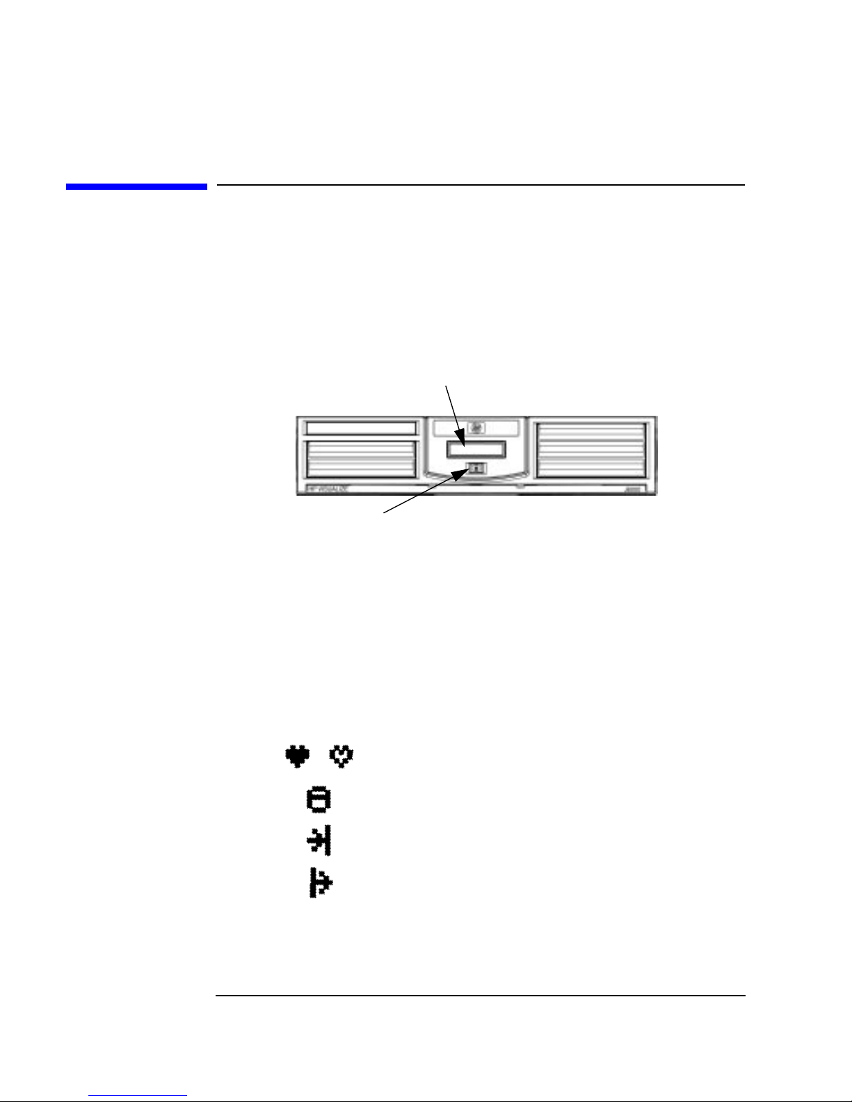
system unit controls. Figure 1-1 shows the system unit front panel
controls.
Figure 1-1 System Unit Front Panel Controls
LCD
Power Switch
System LCD
The Liquid Crystal Display (LCD) is located on the front panel. The LCD
has two 16 characters lines. The LCD displays messages about the state
of the system, including chassis codes. The symbols in Figure 1-2 appear
in the LCD ifyou have the HP-UX 11.0 or 11i operating system booted on
your system. They represent the different system activities shown:
Figure 1-2 LCD Symbols for System Activities
Operating system running (heart beat)
Disk access in progress
Network receive in progress
Network transmit in progress
22 Chapter1
Page 23

System Overview
Your Workstation’s Front Panel Controls
System Power Switch
The power switch is used to turn the system unit on and off. When you
turn your workstation off, the operating system executes an automatic
shutdown -q command. This prevents any damage to programs and data
on your system disk. Turning the power switch back on again
automatically boots up the HP-UX 11.0 or 11i operating system if your
system has been configured to auto boot.
Chapter 1 23
Page 24
System Overview
Your Workstation’s Rear Panel Connectors
Your Workstation’s Rear Panel Connectors
This section describes the following connectors on the system unit’s rear
panel:
• Power cord connector
• Two serial ports
• 802.3 TP (Twisted Pair) LAN connector
• USB connectors
• Single-Ended/Low-Voltage Differential SCSI connector
• 15-Pin D-Sub connector for optional graphics card
• Audio connectors (see the section “Audio Connectors”)
NOTE To maintain FCC/EMI compliance, verify that all cables are fully seated
and properly fastened.
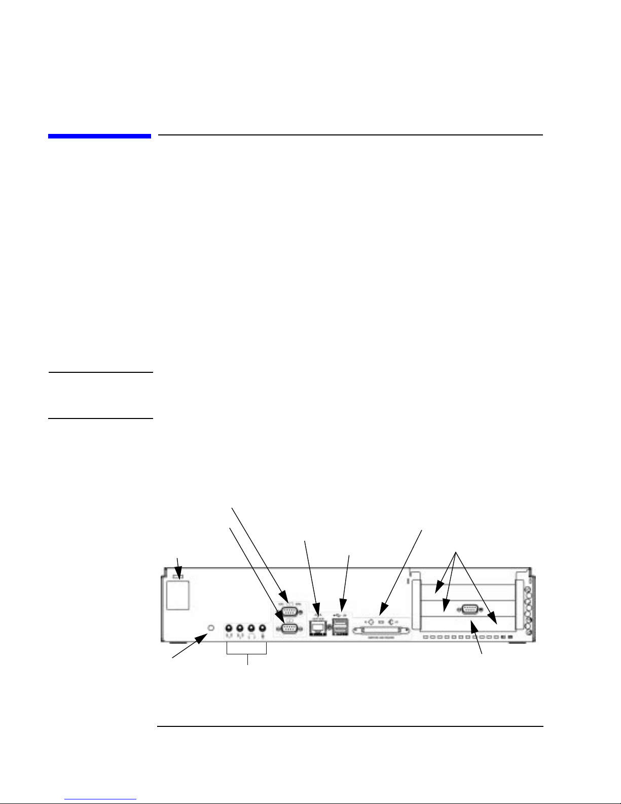
Figure 1-3 shows the locations of the connectors on the system unit’s rear
panel.
Figure 1-3 System Unit Rear Panel Connectors
Serial Port 1
Serial Port 2
Power
Connector
TOC
LAN Connector
USB Connectors
Audio Connectors
SE/LVD SCSI Connector
IO Card Slots
15-Pin D-Sub
Connector
(optional)
24 Chapter1
Page 25
Audio Connectors
Your workstationhas audio input and outputcapability through external
input and output connectors on the rear panel and through an internal
speaker. The rear panel contains the line input jack, line output jack,
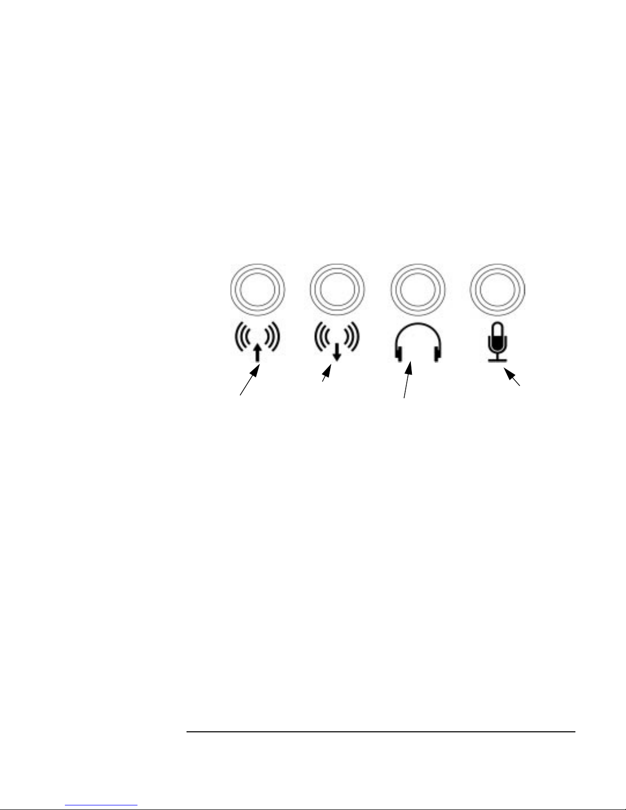
microphone jack, and headphone jack connectors. See Figure 1-4.
Figure 1-4 Audio Connectors
System Overview
Your Workstation’s Rear Panel Connectors
Line Output Jack
Line Input Jack
The audio connectors are standard stereo audio mini-jacks.
Headphone Jack
Microphone Jack
802.3 Network Connectors
Your workstation has a built-in Twisted Pair (TP) connector for the 802.3
(ETHERNET) or 10 BaseT/100 BaseT network. Your workstation will
automatically select the correct network setting.
Chapter 1 25
Page 26

System Overview
Your Workstation’s Rear Panel Connectors
RS-232C Serial Input/Output Connector
You can attach a variety of pointing devices (such as a mouse or
trackball), or peripheral devices (such as printers, plotters, modems, and
scanners) to the RS-232C Serial Input/Output (SIO) ports on this
workstation. Consult the documentation that accompanies each pointing
or peripheral device for specific information concerning its use.
Multi-Mode SCSI Connector
Use the multi-mode SCSI connector to connect external SCSI devices
such as DDS-format tape drives. Note that the SCSI bus for this
connector is independent of the internal SCSI bus.
Consult the documentation that accompanies each SCSI device for
specific information concerning its use. For more information, refer the
Technical Reference.
NOTE When attaching external Single-Ended SCSI (SE SCSI) or Low-Voltage
Differential SCSI (LVD SCSI) devices, be sure to terminate the last
device on the external SCSI bus with a terminator appropriate for that
bus.
You can connect Narrow Single-Ended SCSI devices to the multi-mode
SCSI connector using a 68-pin to 50-pin adapter cable (C2961A – 1M
cable; C2906A – 2M cable). However, you should note:
• If you mix SCSI devices, it will cause bus performance to be that of
the device with the lowest performance.
• If you are connecting a Narrow Single-Ended SCSI (NSE SCSI)
device to theworkstation, make sure it is the last device on the bus. If
a NSE SCSI device is between the workstation and a Wide
Single-Ended SCSI device, data loss will occur.
• FWD SCSI devices will not work on the LVD SCSI bus.
Power Cord Connector
Plug the workstation’s power cord into the power cord connector to
provide AC power to the system.
26 Chapter1
Page 27

System Overview
Memory
Memory
The main memory for an J6700 workstation can vary from a minimum of
1 GBytes to a maximum of 16 GBytes. This workstation has sixteen
memory card slots.
NOTE You must install only matched pairs of 512 MByte and 1 GByte DIMM
cards in these slots (for example, slots 0A and 0B).
To install DIMM cards in your workstation, follow the subsequent
procedure. Also, see Figure 1-5.
1. Turn your workstation off and unplug it.
2. Remove your workstation from its pedestal and lay it on a soft
anti-static surface with the model name and HP VISUALIZE text in the
upright position. See Figure 1-1. (Desk side only)
3. Grasp both ends of the bezel and pull outward from the workstation
to remove it.
4. Unscrew the captive screw located above the Liquid Crystal Display.
5. Pull forward on the cover and lift it off the workstation.
6. Follow theloading sequence located inside the J6700. Also, see Figure
1-6.
Figure 1-5 Desk-side Cover Removal
Cover
Pedestal
Captive Screw
Bezel
LCD
Chapter 1 27
Page 28

System Overview
Memory
Please keep in mind that if memory is installed improperly or is bad your
workstation’s operating system will not boot-up, and a DIMM error will
appear in your workstations LCD. If a DIMM error does occur, please
read the section “Memory Failures” in the chapter “Solving Problems.”
Figure 1-6 Memory Loading Sequence
28 Chapter1
Page 29

System Overview
Monitors
Monitors
The optional graphics cardssupport any VESA monitors that are capable
of a minimum XGA resolution of 1024×768.
Before using your monitor, you should become familiar with its controls,
connectors and indicators. For information on these controls and
indicators and on using your monitor, see the documentation that came
with the monitor.
Note that connection to earlier HP monitors with 15-pin mini-DSub
cables can be made using the A4168A adapter connector shipped with
your system’s miscellaneous kit.
Chapter 1 29
Page 30

System Overview
USB Connectors
USB Connectors
The two Universal Serial Bus (USB) connectors support only the HP
keyboard, mouse and hub (D6804A). You can connect the HP keyboard,
mouse and hub in either of the USB connectors.
The mouse and keyboard were shipped with your system unit, and the
HP hub can be ordered separately. Note that you should consult the
documentation that accompanies each input device for specific
information concerning its use.
For more information on the Universal Serial Bus, use your browser and
the following URL:
http://www.usb.org
Keyboard
The USB connector provides an interface for the keyboard to the system.
This keyboard provides the standard keys found on most PC keyboards.
HP Mouse
The HP mouse (USB) has a left, middle and right buttons that function
the same as most mice. For general information on the various cursor
shapes associated with different areas of HP CDE while using a mouse,
see the Using Your HP Workstation document.
HP Hub for USB Devices
The HP USB hub provides you with the ability to connect more than two
USB devices to your workstation, as well as with the ability to extend
your USB device’s cable length. As an example, you may desire to locate
your workstation’s keyboard and mouse at a greater distance from your
workstation, but your keyboard and mouse cables are not long enough.
To increase the cable length of your keyboard and mouse, you make use
of the USB hub’s extra cable length and connect the hub’s cable to one of
the two connectors on the back of your workstation. You then connect the
keyboard and mouse into their separate connectors on the USB hub.
30 Chapter1
Page 31

System Overview
The Hot-Plug Process
The Hot-Plug Process
The physical aspect of inserting and removing a disk drive is discussed in
the document that comes with your component. However, the operating
system must be prepared for the insertion or removal of a disk, or
unexpected and harmful effects may occur.
There is a significant difference between the terms “hot-pluggable” and
“hot-swappable.” Hot swapping happens at the device level; that is, a
hot-swappable device manages insertion/removal on its own without
assistance from HP-UX commands. The disk drive(s) in the J6xxx are not
hot-swappable; they are merely hot-pluggable. Thus, a manual software
procedure must be done in order to safely remove or insert disk drives
while the system is running.
The reason the hot-plug process exists is that you might need to replace
a defective disk drive in a high-availability system while it is running.
Replacing a Failed Disk Drive
In the context of replacing a failed disk drive, the system administrator
must determine which diskhas failed. Depending on how the system was
set up, the identity of the failed drive may or may not be obvious. This
determination may be done in either of two ways:
• Tracking the error messages written by the LVM (Logical Volume
Manager) to the system console and/or a log file. For information on
LVM commands, see the man pages for vgchange, lvreduce,
vgcfgrestore, lvlnboot, lvextend, lvsync, etc.
• If installed, run the diagnostic utility Support Tool Manager (xstm)to
determine disk malfunction.
The removal of a defective disk drive from an active file system is
supported through LVM commands if hot-pluggable disks have been
configured into the HP-UX file system with LVM. To provide high
availability, without impact to users, the disks must also be configured as
mirrored disks. Disk-mirroring is accomplished through use of the
MirrorDisk/UX software (HP part number B2491BA); for information on
classes, see http://www.hp.com/education/courses/h6285s.html.
No graphical user interface is currently offered through the System
Administration Manager (SAM) for doing the required LVM commands,
Chapter 1 31
Page 32

System Overview
The Hot-Plug Process
because manipulation of the LVM requires specialized knowledge that
only experienced system administrators are expected to have (see below
for details).
Hot-Plug Example
The following example describes a particular system problem where the
solution is to replace a hot-plug disk module.
Volume group /dev/vg00 contains the two disks, with the logical volume
configuration as shown:
Table 1-2 Example Configuration
Volume Description Volume Description
Logical Volume 1 Logical Volume 3
Logical Volume 2 Logical Volume 4
Logical Volume 3 Logical Volume 5
hardware address 10/0/12/0.0 10/0/13/0.0
device file (/dev/dsk/) c2t6d0 c2t5d0
32 Chapter1
Page 33

System Overview
The Hot-Plug Process
The system problem for this example is that the disk at hardware
address 10/0/13/0.0 has a head crash, and as a result, is unusable. The
steps described in the Hot-Plug Procedure section below outline a
method that can be used to recover from this state.
1. All of the replaced disk’s in-use extents must belong to mirrored
logical volumes which were created with the “strict” option (-s); see
the documentation for MirrorDisk/UX.
2. You must have an up-to-date configuration backup file. This is done
automatically each time an LVM command changes LVM
configuration.
The default backup file’s path is:
/etc/lvmconf/<
base_vg_name
>.conf
For example,
/etc/lvmconf/vg00.conf
3. The replacement disk must be the same product ID as the replaced
one.
NOTE HP often uses different manufacturers for disks having the same product
number. The hot-plug manual procedure will not update the disk driver’s
internal information to that of the replaced disk.
The replacement disk will have the same capacity and block size as
the defective disk because they have the same product number. The
only field that could be incorrect is the string specifying the vendor’s
name. This will not affect the behavior of the LVM. If it is desired to
update the manufacturer’s name, the disk’s volume group must be
deactivated and reactivated. See the HP-UX System Administration
Tasks manual for details.
Chapter 1 33
Page 34

System Overview
The Hot-Plug Process
The Hot-Plug Procedure
These are the steps required to properly hot-plug a disk drive:
Step 1
• Check if the LVM found the physical volume to be defective when the
volume group was activated.
• The “vgchange -a y” would have printed the following message on
the console:
WARNING:
VGCHANGE:WARNING: COULDN’T ATTACH TO THE VOLUME GROUP
PHYSICAL VOLUME “/DEV/DSK/cXtXdX”
THE PATH OF THE PHYSICAL VOLUME REFERS TO A DEVICE THAT
DOES NOT EXIST, OR IS NOT CONFIGURED INTO THE KERNEL.
• If the status of the “vgchange -v vg02” is unknown, you may check if
this occurred by doing a vgdisplay command:
vgdisplay 〈VG name〉
For our example:
vgdisplay /dev/vg00
• If the disk was defective at vgchange time, the following messages
will be printed one or more times.
WARNING:
VGDISPLAY: WARNING: COULDN’T QUERY PHYSICAL VOLUME
“/DEV/DSK/cXtXdX”
THE SPECIFIED PATH DOES NOT CORRESPOND TO PHYSICAL VOLUME
ATTACHED TO THE VOLUME GROUP.
VGDISPLAY: WARNING: COULDN’T QUERY ALL OF THE PHYSICAL
VOLUMES
• If you see these messages, the disk was defective at the time the
volume group was activated.
Otherwise, your disk became defective after the vgchange and you must
continue with step 2 of this procedure.
34 Chapter1
Page 35

System Overview
The Hot-Plug Process
Step 2
• Reduce any logical volumes that have mirror copies on the faulty disk
so that they no longer mirror onto that disk (note the -A n option):
lvreduce -m 0 -A n 〈LV name〉 /dev/dsk/<
hard drive
>
(for 1-way mirroring)
For our example:
lvreduce -m 0 -A n /dev/vg00/stand /dev/dsk/c2t5d0
lvreduce -m 0 -A n /dev/vg00/swap /dev/dsk/c2t5d0
lvreduce -m 0 -A n /dev/vg00/ /dev/dsk/c2t5d0
The number of logical volumes that this step needs is variable. For
instance, on a mirror of a root disk you should have at least three
logical volumes: /stand (is lvol1), /swap (is lvol2), and / (is lvol3).
Note that if your root mirror disk dies, you need to do the following:
— Follow the procedure in the section “Initial System Loader (ISL)
Environment” in the chapter “Boot Console Handler” in the
Technical Reference. At the Main Menu prompt boot from the
good disk.
— Type y at the Interact with SPL prompt and press Enter.
— Type this command at the ISL prompt and press Enter: hpux -lq
The -lq option stands for loss of quorum. Once this procedure has
been completed the system will boot.
Step 3
• Replace the faulty disk.
•Doanioscan on the replaced disk to insure that it is accessible and
also as a double check that it is a proper replacement.
For our example:
ioscan /dev/dsk/c2t5d0
Chapter 1 35
Page 36

System Overview
The Hot-Plug Process
Step 4
• Restore the LVM configuration/headers onto the replaced disk from
your backup of the LVM configuration:
vgcfgrestore -n 〈volume group name〉 /dev/rdsk/cxtxdx
where x is the logical unit number of the disk that has been replaced.
For our example:
vgcfgrestore -n /dev/vg00 /dev/rdsk/c2t5d0
Step 5
• Attach the new disk to the active volume group with the vgchange
command.
vgchange -a y /dev/vg00
Step 6
• If this disk is not a mirror of a root disk, then skip this step.
• Run the mkboot command. For our example:
mkboot /dev/rdsk/c2t5d0
• Run lvlnboot -R to relink the replaced disk into the Boot Data
Reserved Area of all the Physical Volumes in the Volume Group.
lvlnboot -R
Step 7
• Run the lvsync command to synchronize the physical extents of each
logical volume specified by logical volume path. Synchronization
occurs only on physical extents that are stale mirrors of the original
extent.
lvsync /dev/<
volume group name
>/<
LV name
>
For example:
lvsync /dev/vg00/stand
lvsync /dev/vg00/swap
lvsync /dev/vg00/
At this stage, your system should be fully functioning. Use the xstm
command to verify.
36 Chapter1
Page 37

System Overview
Workstation Conversion Process
Workstation Conversion Process
If you want to convert your workstation from a desk-side system to a
rack-mount system and from a rack-mount system to a desk-side system,
here are instructions for these tasks.
Desk-Side to Rack-Mount Conversion
To convert your desk-side system to a rack-mount system, you will need
to order the rack-mount kit (HP Part Number: A5993A) from your local
HP Sales Representative. You can find the conversion instructions in the
Technical Reference for the J6700 workstation. This document can be
found at the following URL:
http://www.hp.com/workstations/support/
Rack-Mount to Desk-Side Conversion
To convert your rack-mount system to a desk-side system, you will need
to order the desk-side kit (HP Part Number: A6036A) from your local HP
Sales Representative. You can find the conversion instructions in the
Technical Reference for the J6700 workstation. This document can be
found at the following URL:
http://www.hp.com/workstations/support/
Chapter 1 37
Page 38

System Overview
Workstation Characteristics
Workstation Characteristics
Table 1-3 Workstation Characteristics
Characteristic Description
Weight Rack System (excl. keyboard and display)
Weight Desk-side System (excl. keyboard and display)
Dimensions Rack System Depth: 62.23 cm (24.5 inches)
Dimensions Desk-side System Depth: 65.46 cm (25.77 inches)
Footprint (Desk-side)
Storage temperature −40˚C to +70˚C (−40˚F to +158˚F)
Storage humidity 8% to 90% (relative)
Operating temperature +5˚C to +35˚C (+41˚F to +95˚F)
Operating humidity 15% to 80% (relative)
Input Current 6.2 to 7.4 amps (AC at 100 to 120 Vac)
Input Frequency 47 to 66 Hz
18.14 kg (40 lb.)
21.73 kg (47.9 lb.)
Width: 8.64 cm (3.4 inches)
Height: 42.42 cm (16.7 inches)
Width: 25.37 cm (9.99 inches)
Height: 53.34 cm (19.82 inches)
0.17 m2 (1.79 sq. ft.)
3.2 to 3.7 amps (AC at 200 to 230 Vac)
Sound Power Rack System 6.5 Bels LwA max. at 30˚C (88˚F)
Sound Power Desk-side System 6.0 Bels LwA max. at 30˚C (88˚F)
38 Chapter1
Page 39

2 Getting Your System Running
This chapter explains how to get your system running, set your system
password, and use your CD drive.
39
Page 40

Getting Your System Running
Here are the topics covered in this chapter:
• Information You Need to Record
• Powering Up Your System
• Using Your CD Drive
The instructions in this chapter assume you are using the HP-UX 11.0
operating system and the Workstation Additional Core Enhancements
(ACE) for HP-UX 11.0 (November, 1999) or the HP-UX 11i operating
system and the Hardware Enablement Bundle (HWE) for HP-UX 11i
(June, 2001) with the HP CDE interface.
NOTE Be sure you have read and understand the information on mounting and
unmounting CDs found in the section “Using Your CD Drive” before you
begin using your CD drive.
NOTE This chapter requires you to be superuser (root). If you cannot log in as
root, contact your system administrator.
40 Chapter2
Page 41

Information You Need to Record
Before you begin using your workstation, take a moment to gather the
following important information and record it in the appropriate
subsection for future use:
• Host name
• LAN Station ID
• Internet Protocol (IP) address
• Time zone
• Optional network parameters
• Optional font server parameters
Table 2-1 System Information You Need
Getting Your System Running
Information You Need to Record
Information You Need Record it here... Where to find it...
Host Name This is the system name.
LAN Station ID On the contents label that
came with your
workstation’s shipping
carton. It can also be
found on the back of the
workstation.
Internet Protocol (IP) Address Askthe networkor system
administrator.
Time Zone The time zone where the
workstation is located
(e.g., MST).
Chapter 2 41
Page 42

Getting Your System Running
Information You Need to Record
Table 2-1 System Information You Need
Information You Need Record it here... Where to find it...
Optional network parameters:
Subnetwork mask
Network gateway IP address
Local domain name
DNS server host name
DNS server IP address
Network Information Service domain name
Optional font parameters:
Font server name
Font server IP address
Ask your network or
system administrator.
________________
________________
________________
________________
________________
________________
Ask your network or
system administrator.
________________
________________
42 Chapter2
Page 43

Getting Your System Running
Powering Up Your System
Powering Up Your System
After you have connected the various parts of the workstation—for
details, see the J6000 Quick-Install Poster that came with your
workstation—you are ready to power up the system. At this point, there
are two possibilities:
• Your workstation has been “ignited;” thatis,the HP’s Instant Ignition
process has installed the operating system already. In this case, when
you power up the workstation, you will be presented with a series of
questions asking you the machine’s host name, IP address, subnet
mask, and other basic configuration questions (see the section
“Information You Need to Record”). When these questions are
answered, the CDE login screen will appear.
• Your workstation has not been “ignited;”that is, HP’s Instant Ignition
process has not installed the operating system already. In this case,
you will need to install the operating system from the HP-UX CDs.
For details, see the CD Booklet included with the CDs. When the
operating system is installed, you will need to answer the questions
noted above for the ignited system. After the questions have been
answered, the CDE login screen will appear.
Once the CDE login screen appears and you are logged in as root
(initially there is no password), you will be able to create other users’
accounts and do whatever other configuration and installations required
to get the machine intoits desired state. See the HP CDEGetting Started
Guide and the Common Desktop Environment User’s Guide for
instructions on typical tasks.
Chapter 2 43
Page 44

Getting Your System Running
Powering Up Your System
Turning on the Power
1. Turn on the monitor and any external peripherals (for example,
printers) connected to the workstation.
2. Turn on the workstation. The workstation will run a series of
self-tests. If you are using an old monitor and you are not sure if it
works with your system, you need to press the Tab key several times
until you see the message Monitor Type Selection. Select the
appropriate monitor type from the list of monitors that are displayed,
and press Enter. In response to the next prompt, press y and wait for
15 seconds for the system to continue its boot process.
3. After two or three minutes, a series of messages are displayed as
various hardware and software subsystems are activated. Unless
something is wrong with your system, you are not asked to respond to
these messages.
4. A series of windows appears requesting the information you gathered
in Table 2-1, such as your host name, IP address, and time zone.
Enter the information as it is requested.
NOTE You should enter the host name when requested; otherwise, you will get
an error message when you log in.
If you do not have other pieces of information, press Enter to use the
default value. You can provide missing information later by logging into
a terminal emulator window as superuser and executing this command:
/sbin/set_parms
5. You are now asked if you want to set a root password. Specify the
root password now. The root password is the password used for the
superuser account. The superuser is a special user who has
permission to perform all system administration tasks. The user
name for the superuser is root.
6. When you have finished answering all of the questions, the
workstation completes its start-up sequence and displays the CDE
login screen.
44 Chapter2
Page 45

Getting Your System Running
Powering Up Your System
7. Log into your first CDE session as root. For information on logging
into CDE, see the Common Desktop Environment User’s Guide.
NOTE You must log into the first session as root. This is because the system
contains no other user accounts. Once you have created user accounts,
you should log out as root and log back in as one of the other users.
8. Use the System Administration Manager (Sam) to set up user
accounts.
a. Move the mouse pointer to the Application Manager control for
tools and click the left mouse button. Alternatively you can
execute sam at a terminal window command prompt and skip to
step 5.
b. Double click on the System_Admin icon in the Application
Manager window.
Chapter 2 45
Page 46

Getting Your System Running
Powering Up Your System
c. Double click on the Sam icon in the Application Manager --
System_Admin window. If you are root, the System
Application Manager (Sam) will appear on your screen.
d. Double click on the Accounts for Users and Groups and fill in
the necessary information.
Documentation
The documentation for your system is located on the “Instant
Information” CD. To view this CD, you need to read the special mounting
instructions that came with it.
46 Chapter2
Page 47

Getting Your System Running
Using Your CD Drive
Using Your CD Drive
This section explains how to mount/unmount a CD drive, verify the CD
drive operation, and configure the CD driver. Note that if you are just
using the CD drive to boot your system, you will not need to mount it.
Mounting and Unmounting a CD
This section explains how to mount and unmount a CD using the System
Administration Manager (SAM).
The procedures in this section require you to log in as root. If you cannot
log in as root, contact you system administrator.
Mounting a CD Using SAM
To access the CD in your CD drive, you must mount it. This applies to
CDs with file system information only. Ifyou wish to load a music CD, for
example, you would not need to mount it. Mounting a CD with file
system information gives it a path name that allows your workstation to
communicate with it. You must unmount the CD before removing it from
the drive.
To mount a CD on an HP-UX 11.0 or 11i operating system, perform the
steps covered in this section.
1. Log in as root.
2. Move the mouse pointer to the Application Manager control for
tools and click the left mouse button. Alternatively you can execute
sam at a terminal window command prompt and skip to step 5.
Chapter 2 47
Page 48

Getting Your System Running
Using Your CD Drive
3. Double click on the System_Admin icon in the Application
Manager window.
4. Double click on the Sam icon in the Application Manager -System_Admin window.
The System Application Manager (Sam) will appear on your
screen.
5. Double click on the Disks and File Systems icon.
48 Chapter2
Page 49

Getting Your System Running
Using Your CD Drive
6. Double click on the Disk Devices icon.
The following screen message is displayed:
Scanning the system’s hardware...
The Disks and File Systems window opens containing a list of
devices installed in this system. From the list of devices, choose the
CD drive you would like to configure as a file system by clicking on
the device to highlight it.
7. Click on Add in the Actions menu. For this example you will select
the item Not Using the Logical Volume Manager. However, you
can select any appropriate item from the Actions menu.
8. Enter the mount directory name (for example, /CD) in the Mount
Directory field of the Add Disk without LVM window.
9. Click on the Modify Defaults... button. In the Modify Defaults
window, select the Read Only item from the Access button menu.
Next, unselect the Create New File System item by clicking on it.
Exit the Modify Defaults window by clicking on the OK button.
10.Click on the OK button in the Add Disk without LVM window. It
will take a short time for the CD to mount. When the Add Disk
without LVM window disappears and CDFS appears in the Use
column of the Disks and File Systems window, the CD is mounted.
Chapter 2 49
Page 50

Getting Your System Running
Using Your CD Drive
Unmounting a CD Using SAM
You must unmount a CD before it will eject from the drive.
NOTE Before you unmount a CD, make sure that your working directory is on
some other disk or medium.
To unmount a CD on an HP-UX 11.0 or 11i operating system, perform
the steps covered in this section.
1. Log in as root.
2. Move the mouse pointer to the Application Manager control for
tools and click the left mouse button. Alternatively you can execute
sam at a terminal window command prompt and skip to step 5.
3. Double click on the System_Admin icon in the Application
Manager window.
50 Chapter2
Page 51

Getting Your System Running
Using Your CD Drive
4. Double click on the Sam icon in the Application Manager -System_Admin window.
The System Application Manager (Sam) will appear on your
screen.
5. Double click on the Disks and File Systems icon.
6. Double click on the Disk Devices icon.
The following screen message is displayed:
Scanning the system’s hardware...
The Disk and File Systems window opens containing a list of
devices installed in this system. From the list of devices, choose the
CD drive you would like to remove (unmount) by highlighting that
device.
Chapter 2 51
Page 52

Getting Your System Running
Using Your CD Drive
7. Clickon Remove in the Actions menu. Click Yes in the confirmation
window. This unmounts the CD. Note that it will take a short time for
the CD to be unmounted. The CD is successfully unmounted when
you see Unused in the Use column of the Disk and File Systems
window.
Verifying the CD Drive Operation
To verify that your workstation can communicate with the CD drive,
follow the steps covered in this section. Note that to perform the steps
required in this section, you must be superuser (root). If you cannot log
in as root contact your system administrator.
1. Log in as root.
2. Type the following command at the shell prompt and press Enter:
/usr/sbin/ioscan -d sdisk
After a few seconds the ioscan utility lists all of the I/O devices that
use the “sdisk” driver. Your CD drive should be among the devices
listed. A list similar to the following will appear:
H/W Path Class Description
===============================================
10/0/15/1.5.0 disk SEAGATE ST39102LC
10/0/15/1.6.0 disk SEAGATE ST39102LC
10/0/14/0.0.0 disk TEAC CD-532E-B
If ioscan does not detect any usable I/O system devices, such as the
CD drive, nothing is output and you are returned to the system
prompt. Since this indicates possibly that the driver for the CD drive
is not configured, read the subsequent section “Configuring the CD
Driver.”
Configuring the CD Driver
If you reload software or rebuild the Instant Ignition system on your
workstation, you may need to reconfigure the HP-UX kernel to add the
CD driver. Use the SAM utility to add the CD driver and build a new
HP-UX kernel.
52 Chapter2
Page 53

Getting Your System Running
Using Your CD Drive
For more information about how to reconfigure the kernel using SAM,
see the following manuals:
• Managing Systems and Workgroups
• Using HP-UX
Chapter 2 53
Page 54

Getting Your System Running
Using Your CD Drive
54 Chapter2
Page 55

3 Troubleshooting Your System
This chapter contains troubleshooting information to help you solve
system problems. If you have a workstation problem that is not listed in
this chapter, or if your problem persists, contact your designated HP
support representative.
55
Page 56

Troubleshooting Your System
To help speed up your service request, have your system’s model number
and serial number available. Your HP service representative will always
ask for these numbers.
The instructions in this chapter assume you are using the HP-UX 11.0
operating system and the Workstation Additional Core Enhancements
(ACE) for HP-UX 11.0 (November, 1999) or the HP-UX 11i operating
system and the Hardware Enablement Bundle (HWE) for HP-UX 11i
(June, 2001) with the HP CDE graphical interface. When using HP CDE,
you will have to use command line options in a terminal window to
perform tests.
Here are the topics covered in this chapter:
• Common Problems and Solutions
• Dealing with a Boot Failure
• Memory Failures
• Using the LCD for Troubleshooting
• Using the System Board LEDs for Troubleshooting
• Troubleshooting Monitor Problems
• Running System Verification Tests.
NOTE This chapter requires you to log in as root. If you cannot log in as root,
contact your system administrator.
If you have to replace, reseat, or reconnect any of the components in this
workstation, see the section “Opening Your Workstation” in this chapter
and the “Parts Replacement and Removal Instructions” that were
shipped with the part your are replacing.
56 Chapter3
Page 57

Troubleshooting Your System
Opening Your Workstation
Opening Your Workstation
Since a few of the troubleshooting solutions require that you get inside of
your workstation, this section provides a procedure for doing this.
NOTE If you have to remove the J6700 cover to implement a solution, you will
have to replace it to determine if your solution worked. The
safety-interlock switch keeps the system from working when the cover is
removed.
To remove the cover of your workstation, follow the subsequent
procedure. Also, see Figure 3-1.
1. Turn your workstation off and unplug it.
2. Remove your workstation from its pedestal and lay it on a soft
anti-static surface with the model name and HP VISUALIZE text in the
upright position. See Figure 1-1. (Desk side only)
3. Grasp both ends of the bezel and pull outward from the workstation
to remove it.
4. Unscrew the captive screw located above the Liquid Crystal Display.
5. Pull forward on the cover and lift it off the workstation.
Figure 3-1 Desk-side Cover Removal
Cover
Pedestal
Captive Screw
Bezel
LCD
Chapter 3 57
Page 58

Troubleshooting Your System
Opening Your Workstation
Figure 3-2 shows a topview of the components you mightneed to replace,
reseat or reconnect.
Figure 3-2 Top View of the Workstation Components
SCSI Connector
IDE
Connector
VRM0
System Board
Memory Cards
5-pin Power
Connector
24-pin Power
Connector
Internal
LCD
Connector
VRM1
External LCD Connector
58 Chapter3
Page 59

Common Problems and Solutions
The tables in this section list common problems you may encounter with
your computer. The tables also explain how to solve the problems.
Table 3-1 Problems Powering Up the System
Problem Solution
Troubleshooting Your System
Common Problems and Solutions
The LCD does not light
up.
The LCD lights up, but
is blank.
Make sure your AC power cord is connected securely to the
system.
Make sure the power cord is plugged into a working AC outlet.
Make sure the power is turned ON.
Make sure the safety-interlock switch is pressed inward by
closing the system cover.
Check the system VRM0 and VRM1 LEDs. See the section
“Using the System Board LEDs for Troubleshooting” in this
chapter.
Make sure the LCD control cable is properly connected inside
the system unit and on the front part of the chassis behind the
bezel.
Check the system FETCH LED. See the section “Using the
System Board LEDs for Troubleshooting” in this chapter.
Make sure the LCD control cable is properly connected inside
the system unit.
The LCDlight is on and
a row of boxes appears
LCD displays an error
message.
If problems persist, contact your system administrator or call your designated service
representative.
Chapter 3 59
Contact your local HP Support Representative.
See “Using the LCD for Troubleshooting” later in this chapter.
Page 60

Troubleshooting Your System
Common Problems and Solutions
Table 3-2 Problems Loading and Booting the Operating System
Problem Solution
The LCD is lit, and text
appears on the screen,
but more than two
Make sure that the system is not in soft power off mode by
pressing on the power switch located on the front of the
workstation.
minutes have passed
with no sign of system
activity.
Make sure that all externalSCSI devices are set to the proper
SCSI ID. (See the documentation that came with your SCSI
device.)
Check that all SCSI devices are correctly cabled. Check that
the SCSI bus is correctly terminated.
Check that the LAN cable is connected and the LEDs on the
LAN connector are blinking.
The system stops or
hangs while booting.
Followthe instructions in “Dealing witha Boot Failure” later
in this chapter.
If the LCD displays a DIMM error,follow the instructions in
“Memory Failures” later in this chapter.
If problems persist, contact your system administrator or call your designated service
representative.
Table 3-3 Problems with the 802.3 Network
Problem Solution
Cannot reach other
systems on the network.
Applications that rely on
Check the network connector on the back of the system
unit. Make sure the network cable or transceiver is
fastened securely to the connector.
the network will not run.
If problems persist, contact your system administrator or call your designated service
representative.
60 Chapter3
Page 61

Table 3-4 Problems Using a Hard Disk Drive
Problem Solution
Troubleshooting Your System
Common Problems and Solutions
The disk drive is not
accessible or does not
respond.
Make sure that all SCSI devices are set to the proper SCSI
ID. (See the documentation that came with your SCSI
device.)
Check that all SCSI devices are correctly cabled. Check
that the SCSI bus is correctly terminated.
Follow the instructions in “Dealing with a Boot Failure”
later in this chapter.
If the disk drive is external to the system unit, make sure
that its power is turned ON.
If problems persist, contact your system administrator or call your designated service
representative.
Table 3-5 Problems Using the CD Drive
Problem Solution
The CD drive does not
respond to commands (for
Re-enter the commands and make sure you have typed
them correctly.
example, mount or
swinstall).
See the section “Running System Verification Tests” later
in this chapter to verify that the CD drive is functioning
properly.
If problems persist, contact your system administrator or call your designated service
representative.
Chapter 3 61
Make sure power and data cables are connected.
Page 62

Troubleshooting Your System
Dealing with a Boot Failure
Dealing with a Boot Failure
If your usual boot device (typically a disk) is not responding as it should,
you try to boot from the disk (or another boot device) by selecting it
manually. Note that you must use the boot console handler (bch) to
perform the steps in this section.
To boot a device manually, follow these steps:
NOTE A common cause of boot failures is forgetting to connect your
Low-Voltage Differential SCSI terminator to the connector on the backof
the last external SCSI device.
NOTE Your computer automatically shuts down the operating system before it
terminates the power.
1. Power on your computer after your system has completely shut down.
If auto boot is turned off, the boot sequence automatically stops at
the boot console Main Menu.Ifauto boot is turned on, you will see
the following message:
Processor is starting auto boot process. To
discontinue, press any key within 10 seconds.
If auto boot and auto search are both turned on, you will see the
following message:
Processor is booting from first available device. To discontinue, press any key within 10
seconds.
NOTE If you are using a power-saving monitor, you will have less than 10
seconds from the time this message appears to press a key.
62 Chapter3
Page 63

Troubleshooting Your System
Dealing with a Boot Failure
2. Press a key. You will then see the message:
Boot terminated
The Main Menu of the boot console appears.
3. At the Main Menu prompt, type the following and press Enter:
Main Menu: Enter command > search ipl
This causes your computer to search exhaustively for bootable media.
4. Boot from one of the listed devices by typing the following at the
prompt and press Enter:
Main Menu: Enter command > boot
where
device
is the hardware path to the device, specified in
device
mnemonic style notation, such as FWSCSI.5.0.
5. Answer “N” to the question, INTERACT WITH IPL (Y,N,Q)?
6. If your computer still fails to boot, there is either something wrong
with the file system or with the hardware. If you suspect a file system
failure, see the manual Using HP-UX for help on dealing with file
system failures. If you think that something is wrong with the
hardware, continue reading this chapter for more troubleshooting
information.
Chapter 3 63
Page 64

Troubleshooting Your System
Memory Failures
Memory Failures
A memory failure will show up in the LCD on your system unit’s front
panel as a DIMM error. See the section “LCD DIMM Failure Message” in
this chapter. Your system’s Boot Console Interface will never appear.
A possible solution to the memory failure problem is to remove the
memory cards and reinstall them. If the problem persists, replace the
failing DIMM cards as indicated in the system’s LCD.
64 Chapter3
Page 65

Troubleshooting Your System
Using the LCD for Troubleshooting
Using the LCD for Troubleshooting
If you should receive a failure or warning in your LCD (located on the
front of your workstation), you should record the information and call in
the problem to your local HP Support Representative. The
representative will need this information to help determine the course of
action to take.
Your computer uses an LCD panel to display firmware/OS progress
codes. The codes, referred to as chassis codes, consist of one of the
mnemonics listed below, followed by a 4-digit hexadecimal number
identifying the code module being executed. The mnemonics and their
meanings are:
FLT A hardware error has been detected
TST Hardware being tested
INI Hardware being initialized
SHU System being shutdown
WRN A non-optimal or unusual operating condition exists
RUN Computer is running operating system
In general, the LCD display has the following format:
Line 1
Line 2
MMM Three character mnemonic
CCCC Four digit hexadecimal code
FFFFFF Six character field replaceable unit
description
DDDDDDDDDDDDDDDD Description of the chassis code
Chapter 3 65
Page 66

Troubleshooting Your System
Using the LCD for Troubleshooting
If the system encounters a FLT code while the system is booting, the FLT
code is interpreted and a message is displayed. For example, you may
have information similar to the following in the LCD:
FLT Three character chassis code
30FC Four digit hexadecimal code
SYS BD Six character field replaceable unit
description
bad sys bd id Description of the chassis code
LCD DIMM Failure Message
This section provides an example of a DIMM failure message, and what
to do if it occurs.
FLT 7853: DIMM
MBE in DIMM 3a
Table 3-6 Description of the LCD Message
FLT Three character chassis code
7853 Four digit hexadecimal code
DIMM Six character field replaceable unit
description
MBE in DIMM 3a Description of the chassis code
If you get the above error in your display, turn off the system and reseat
the DIMM card in slot 3a. If reseating this DIMM card does not work,
you will need to replace the card.
66 Chapter3
Page 67

Troubleshooting Your System
Using the System Board LEDs for Troubleshooting
Using the System Board LEDs for
Troubleshooting
This section provides a description of the system board’s Light Emitting
Diodes (LEDs) and how to use them for troubleshooting. These LEDs are
located inside of the workstation on the system board’s left-back edge.
See Figure 3-3. Note that you will have to view these LEDs through the
airflow holes on the back of your workstation.
NOTE The SUPPLY LED is not currently implemented. Therefore, it does not
provide any troubleshooting information.
Figure 3-3 System Board LEDs
For those system problems that this section is not able to solve, you will
have to call your local HP Support Representative. Before you call,
record the state (on, off or blinking) of your LEDs and give this
information to your local HP support representative. The representative
will use this information to determine the course of action to take.
Chapter 3 67
Page 68

Troubleshooting Your System
Using the System Board LEDs for Troubleshooting
Interpreting the LED Information
Table 3-7 explains how to interpret the information the system board
LEDs provide.
Table 3-7 Interpreting the System Board LEDs
LED Name LED’sColor
Description
When On
VRM1 Green This light, when on, indicates that the
voltage regulator module is working
correctly for processor one.The default state
for this light is on.
VRM0 Green This light, when on, indicates that the
voltage regulator module is working
correctly for processor zero. The default
state for this light is on.
FETCH Green This light, when on, indicates that one or
both processors is fetchingcode. The default
state for this light is on.
FANS Yellow
(blinking)
Note that the yellow light blinks a heart beat
when the system is working correctly. See
Table 3-8 for more details for interpreting
the blinks of this light.
Over Current Red This light, when on, indicatesthere is a short
somewhere in the system. The default state
for this light is off.
There are six LED blink sequences supported by the System Controller.
The LED blink sequences are shown in Table 3-8. Note that each blink of
the LED represents a tenth of a second (0.1 sec.).
68 Chapter3
Page 69

Using the System Board LEDs for Troubleshooting
If the FANS LED is ever stuck either ON or OFF, a system problem has
occurred. This system problem is most likely an I2C bus hang. A
potential fix may be to check that the power supply cables are correctly
plugged in. If this does not work, call you local HP Support
Representative.
Table 3-8 Blink Sequences for the FANS LED
Troubleshooting Your System
Blink
Sequence
Number
(black dot represents0.1 second LED on; white dot
LED Blink Sequence
is 0.1 second LED is off)
Description
System Controller Non-error Blink Sequences
1
● ❍ ● ❍ ❍ ❍ ❍ ❍ ❍ ❍ System controllers
normal heart beat.
2
● ● ● ● ● ❍ ❍ ❍ ❍ ❍ This is a transient state
shown by the system
controller at power up.
3 ●●●●●●●●●●❍❍❍❍❍❍❍❍❍❍ System controller’s
transient state.There is
no system problem.
System Controller Error Blink Sequences
4
● ❍ ❍ ❍ ❍ ❍ ❍ ❍ ❍ ❍ System controller shut
offpower tothe system
because the ambient
temperature exceeded
60˚C or 140˚F.
5
6
● ● ● ● ● ● ● ● ● ❍ System controller
● ❍ ● ❍ ● ❍ ❍ ❍ ❍ ❍ System controller is
Chapter 3 69
detects a fan failure. If
this happens you need
to read the message in
the LCD on the front
of the workstation.
reporting an error.
Page 70

Troubleshooting Your System
Using the System Board LEDs for Troubleshooting
Troubleshooting with System Board LEDs
This section explains what to do when you see the LEDs on your system
board in a non-default state, and when the yellow FANS LED displays
certain blink sequences. For the default states, see Table 3-7. Note that
the non-default state is a state that should not exist, and it is a state that
requires a solution.
Table 3-9 Solutions for the Non-Default LED States
1
LED Name
Non-Default
State
VRM1 OFF If the following solutions do not bring this LED back on,
replace VRM1 board.
• Swap VRM cards to determine if VRM1 is bad
• Determine that the power cable to the system is plugged in
• Check that the power button has been pressed on
• Re-seat the VRM1 board in its connector
• Check that the VRM1 connector cable is properly plugged
in
Solution
VRM0 OFF If the following solutions do not bring this LED back on,
replace VRM0 board.
• Swap VRM cards to determine if VRM0 is bad
• Determine that the power cable to the system is plugged in
• Check that the power button has been pressed on
• Re-seat the VRM0 board in its connector
• Check that the VRM0 connector cable is properly plugged
in
FETCH OFF If the following solutions do not bring this LED back on,
replace the system board.
• Look at the system’s LCD to determine if the firmware
update process has been interrupted
• Determine that the power cable to the system is plugged in
• Check that the power button has been pressed on
• Determine that all external peripheral devices are turned on
and that their cables are properly connected
• Check that all internaldevices are poweredon and that their
cables are properly connected
70 Chapter3
Page 71

Using the System Board LEDs for Troubleshooting
Table 3-9 Solutions for the Non-Default LED States
LED Name
Non-Default
Solution
1
State
Troubleshooting Your System
FANS OFF or blink
sequence 4, 5
or 6
If the following solutions do not bring the LED back on or
cause it to properly blink, replace the system board.
OFF Unplug the system and replace the system
board
Blink Sequence 4 Unplug the system and operate the unit
when its environment gets cooler
Blink Sequence 5 Replace the fan associated with the
message in your system LCD. If power
supply fans are bad, you have to replace
the power supply. If the PCI fan is bad,
replace it. If either one of the processor
fans are bad, you must replace the system
board. Note, fans may stillbe spinning, but
their control signal may have failed.
Blink Sequence 6 Check that the 24-pin power supply signal
cable is properly connected
Press the power button off and unplug the
system and wait for two minutes before
turning the system back on
SHORT ON If the following solutions do not turn this LED off, replace the
1. The LEDs are in the OFF state, or in the case of the FANS LED, the LED is blinking
sequence 1, 2, or 6 or it is not blinking.
Chapter 3 71
system board.
• Check that no pieces of metal are shorting connections
anywhere in the system
• Check that no pins on system connectors are bent and
touching each other
Page 72

Troubleshooting Your System
Troubleshooting Monitor Problems
Troubleshooting Monitor Problems
In the event that your console does not display or stops displaying to
your graphics device, use the following procedure to set the console for
displaying to an external terminal.
Here are the steps to follow:
1. Turn system power off.
2. Disconnect the computer keyboard connector from the system rear
panel.
3. Connect a serial terminal to the Serial 1 connector (the top serial
connector) on the system rear panel. Configure the terminal for: 9600
baud, No Stop Bits, No Parity, 8 Bits.
4. Power on the system. The system will now display the console to the
terminal connected to Serial 1 port. Note that you can use a 9-pin to
9-pin serial cable (HP F1044-80002) to connect a serial terminal or
terminal emulator on a Personal Workstation or Laptop computer.
5. Set the monitor type and path using the Boot Console Handler. For
information on doing this see the chapter “The Boot Console Handler”
in the Technical Reference.
72 Chapter3
Page 73

Troubleshooting Your System
Running System Verification Tests
Running System Verification Tests
HP-UX uses a diagnostics product called MESA that includes the
Support Tools Manager (STM), which allows system operation
verification. To use STM, you need to be on an HP-UX 11.0 or 11i
operating system and HP-UX Diagnostic/IPR Media on your computer.
There are three interfaces that allow you access to the Support Tools
Manager: a command line interface (accessed through the cstm
command), a menu-driven interface (accessed through the mstm
command), and the graphical user interface (accessed through the xstm
command).
For more information on these user interfaces, see the online manual
pages by entering one of the following commands at the command line
prompt and pressing Enter:
man cstm
man mstm
man xstm
Chapter 3 73
Page 74

Troubleshooting Your System
Running System Verification Tests
74 Chapter3
Page 75

A Regulatory Statements
This Appendix contains electromagnetic compatibility information and
optical and acoustical statements.
75
Page 76

Regulatory Statements
Declaration of Conformity
according to ISO/IEC Guide 22 and EN 45014
Manufacturer: Hewlett-Packard Company
Declares that the:
Product Name: HP Workstations
Model Numbers: J6700
Base Product Number: 5X
Product Options: All
conforms to the following specifications:
Safety. IEC 950:1991+A1+A2+A3+A4/EN 60950:1992+A1+A2+A3+A4+A11
EMC. CISPR 11: 1997 / EN 55011: 1998 Class A
3404 East Harmony Rd.
Fort Collins, CO 80528
USA
IEC 60825-1:1993/EN60825-1:1994+A11 Class 1 for LEDs
USA 21CFR Subpart J – for FC Laser module
China GB4943-1995
Russia GOST R 50377-92
CISPR 22: 1993+A1+A2 / EN 55022: 1994+A1+A2 Class A
EN 50082-1: 1992
Also compliant with...
IEC 1000-3-2:1994/EN 61000-3-2:1998
IEC 1000-4-2:1995+A1/ EN 61000-4-2:1999 - 4kV CD, 8kV AD
IEC 1000-4-3:1995/EN 61000-4-3:1996 - 10V/m
IEC 1000-4-4:1995/EN 61000-4-4:1995 - 2kV Signal, 4kV Power Lines
US FCC Part 15, Class A
Japan VCCI Class A
Australia/New Zealand AS/NZS 2046.1/2:1992, AS/NZS 3548:1995, and AS/NZS 4251.1:1994
China GB9254-1988
Taiwan CNS 13438 Class A
Russia GOST R 29216-94
and is certified by:
UL Listed to UL1950, 2nd edition, File E146385
cUL Listed to CSA 22.2 No. 950-M93
TÜV Certified to EN60950 2nd edition with A1+A2+A3+A4+A11
HP Fort Collins CCQD HQE
supplementary information:
The product herewith complies with the requirements of the following Directives and carries the CE marking accordingly:
- the EMC directive 89/336/EEC and 92/31/EEC and 93/68/EEC
- the Low Voltage Directive 73/23/EEC and 93/68/EEC
This product was tested in a typical Hewlett-Packard workstation configuration.
Original signed by Ruth Lutes, Site Quality Manager, Fort Collins, CO, USA
For Compliance Information ONLY, contact:
European Contact: Your local Hewlett-Packard Sales and Service Office or Hewlett-Packard GmbH, Department
HQ-TRE Standards Europe, Herrenberger StraBe 130, D-71034 Boblingen (FAX: 49-7031-14-3143)
Americas Contact:Hewlett-Packard, Fort Collins SiteQuality Manager,mail stop 46, 3404 E. Harmony Rd.,Ft. Collins,
CO 89528, USA
76 AppendixA
Page 77

Regulatory Statements
Electromagnetic Compatibility
Electromagnetic Compatibility
Federal Communications Commission (FCC)
This equipment has been tested and found to comply with the limits for a
Class A digital device, pursuant to Part 15 of the FCC Rules and the
Canadian Department of Communications. These limits are designed to
provide reasonable protection against harmful interference when the
equipment is operated in a commercial environment. This equipment
generates, uses, and can radiate radio frequency energy and, if not
installed and used in accordance with the instruction manual, may cause
harmful interference to radio communications. Operation of this
equipment in a residential area is likely to cause harmful interference in
which case the user will be required to correct theinterference at his own
expense.
Operation of this device is subject to the following conditions:
• This device may not cause harmful interference.
• This device must accept interference received, including interference
that may cause undesired operation.
• Cables used with this device must be properly shielded to comply
with the requirement of the FCC.
• You are cautioned that any changes or modifications not expressly
approved in this manual could void your authority to operate this
equipment.
Appendix A 77
Page 78

Regulatory Statements
Electromagnetic Compatibility
VCCI Statement for Class A Products
Korea RRL Statement for Class A Product
Taiwan Class A Warning
78 AppendixA
Page 79

Regulatory Statements
Optical and Acoustical Statements
Optical and Acoustical Statements
Visible LED Statement
The LEDs on this product are classified as “Class 1 LED Product” in
accordance with EN 60825-1.
Laser Safety Statement for a Class 1 Laser Product
The CD-ROM mass-storage system is certified as a Class 1 laser product
under the U.S. Department of Health and Human Services (DHHS)
Radiation Performance Standard according to the Radiation Control for
Health and Safety Act of 1968.
This means that the mass-storage system does not product hazardous
laser radiation. Because laser light emitted inside the mass-storage
system is completely confined within protective housings and external
covers, the laser beam cannot escape from the machine during any phase
of user operation.
Regulation on Noise Declaration for Machines
Lpa < 70 dB operator position, normal operation, per ISO 7779
Lpa < 70 dB am Arbeitsplatz, normaler Betrieb, nach DIN 45635 T.19
Appendix A 79
Page 80

Regulatory Statements
Optical and Acoustical Statements
80 AppendixA
Page 81

Index
Numerics
802.3 twisted pair LAN
connector
A
Audio connectors
Audio electrical specifications
25
B
Boot failure
C
CD drive, verifying
CD-ROM, mounting and
unmounting
Connector
802.3 twisted pair LAN
Audio
LAN (802.3 Twisted Pair)
Low-VoltageDifferentialSCSI
24
Power cord
RS-232C serial I/O
USB
, 24, 30
Controls, front panel
cstm
, 73
D
disk
, 52
Disk Drive
Failure
Driver, disk
E
Electrical specifications, audio
25
Electrostatic discharge (ESD)
16
EMI compliance
ESD (electrostatic discharge)
, 24, 25
, 24, 25
, 62
, 52
, 47
, 25
, 24, 25
, 24
, 24, 26
, 24, 26
, 22
, 31
, 52
, 24
,
,
,
, 16
F
Front panel controls
G
graphics, optional
H
Headphones jack
Hot-Plug
Disk Drives
Example
Procedure
HP hub, USB
HP mouse, USB
HPVISUALIZEJ6000 Features
19
Hub, HP USB devices
I
I/O, standard connectors
Instant ignition
,
Instant Information
Internal storage devices
Internet protocol (IP) address
41
ioscan
, 52
K
Keyboard, USB
L
LAN station ID
LCD symbols
Line input jack
Line output jack
Liquidcrystal display(LCD)
65
Logical Volume Manager(xstm)
31
Low-Voltage Differential (LVD)
SCSI
, 31
, 32
, 34
, 30
, 22
, 20, 24
, 22
, 19
, 24
, 30
, 21, 43
, 46
, 30
, 41
, 24
, 24
, 30
, 20
, 19
,
,22,
LVM (Logical VolumeManager),
31
M
Mask, subnetwork
Memory failures
Memory, main
Microphone jack
Monitor, troubleshooting
Monitors
Mounting, CD-ROM
Mouse, HP
mstm
N
,
Network, standard
O
Operating system overview
P
Panel controls, front
Parallel connector
PCI slots
Peripheral component
Power cord connector
Power input
Power switch
Power, turning on
Powering up your system
Product description
R
Rear panel
Headphones jack
I/O card slots
Line input jack
,
Line output jack
Microphone jack
Power input
, 19, 29
, 30
, 73
, 20
interconnect (PCI) slots
, 41
, 64
, 19, 27
, 24
, 47
, 19
, 22
, 24
, 24
, 24
, 23
, 44
, 19
, 24
, 24
, 24
, 24
, 24
, 24
, 72
, 21
, 20
, 43
Index 81
Page 82

Index
Serial interface port, 24
TOC button
USB ports
Rear panel connectors, system
unit
Remote power-on
RS-232C serial I/O connector
24, 26
S
Serial interface port (RS-232C)
20
set_parms
shutdown -q
Specifications, audio electrical
25
Subnetwork mask
Support Tool Manager (xstm)
Switch, power
Symbols, LCD
System LCD
System overview, operating
System unit rear panel
connectors
System verification tests,
running
System, powering up
, 24
, 24
, 24
, 20
,
, 44
, 23
, 41
, 31
, 23
, 22
, 22
, 21
, 24
, 73
, 43
V
Verifying, CD drive
X
xstm
, 31, 73
,
,
, 52
T
TOC button
U
Universal serial bus (USB)
Unmounting, CD-ROM
USB
HP Hub
HP mouse
Keyboard
USB connectors
USB ports
, 24
, 20
, 50
, 30
, 30
, 30
, 24, 30
, 24
82 Index
 Loading...