

Page 1

HP Virtual Connect for c-Class BladeSystem
J
User Guide
Part Number 416818-007a
uly 2008 (Seventh Edition)
Page 2

© Copyright 2006-2008 Hewlett-Packard Development Company, L.P.
The information contained herein is subject to change without notice. The only warranties for HP products and services are set forth in the express
warranty statements accompanying such products and services. Nothing herein should be construed as constituting an additional warranty. HP
shall not be liable for technical or editorial errors or omissions contained herein.
Microsoft is a U.S. registered trademark of Microsoft Corporation.
Intended audience
This document is for the person who installs, administers, and troubleshoots servers and storage systems.
HP assumes you are qualified in the servicing of computer equipment and trained in recognizing hazards
in products with hazardous energy levels.
Page 3

Contents
Setup........................................................................................................................................... 7
Virtual Connect overview............................................................................................................................ 7
Pre-deployment planning ............................................................................................................................7
Hardware setup overview........................................................................................................................... 9
Default module configuration .......................................................................................................... 10
Virtual Connect Manager setup overview ...................................................................................................10
Component identification............................................................................................................. 12
HP 1/10Gb VC-Enet Module components and LEDs ....................................................................................12
HP 1/10Gb VC-Enet Module components ........................................................................................12
HP 1/10Gb VC-Enet Module LEDs...................................................................................................13
HP 1/10Gb VC-Enet Module system maintenance switch ................................................................... 14
HP 1/10Gb-F VC-Enet Module components and LEDs ..................................................................................16
HP 1/10Gb-F VC-Enet Module components ...................................................................................... 16
HP 1/10Gb-F VC-Enet Module LEDs ................................................................................................ 16
HP 1/10Gb-F VC-Enet Module system maintenance switch .................................................................18
HP 4Gb Fibre Channel Module components and LEDs .................................................................................19
HP 4Gb VC-FC Module components ................................................................................................ 19
HP 4Gb VC-FC Module LEDs .......................................................................................................... 20
VC-FC Module system maintenance switch........................................................................................ 21
Installation ................................................................................................................................. 22
Supported configurations ......................................................................................................................... 22
HP BladeSystem c7000 Enclosure supported configurations................................................................22
HP BladeSystem c3000 Enclosure supported configurations................................................................24
Installation guidelines............................................................................................................................... 24
Virtual Connect and EBIPA.............................................................................................................. 25
Installing the HP 1/10Gb VC-Enet Module ................................................................................................. 26
Installing the HP 1/10Gb-F VC-Enet Module ............................................................................................... 28
Installing SFP transceivers ............................................................................................................... 30
Removing SFP transceivers.............................................................................................................. 31
Installing the HP 4Gb Virtual Connect Fibre Channel Module........................................................................ 32
Factory default settings................................................................................................................... 33
Firmware requirements................................................................................................................... 33
Recommended stacking connections .......................................................................................................... 34
Loop prevention ...................................................................................................................................... 36
Connecting Virtual Connect Ethernet module uplinks .................................................................................... 36
Configuration example using a Cisco Core switch ............................................................................. 39
Failover and check-pointing......................................................................................................................41
HP Virtual Connect Manager........................................................................................................ 43
Configuring browser support .................................................................................................................... 43
Virtual Connect and RDP .......................................................................................................................... 43
Accessing HP Virtual Connect Manager ..................................................................................................... 44
Command line overview................................................................................................................. 44
Logging on to the HP Virtual Connect Manager GUI .................................................................................... 45
HP Virtual Connect Home......................................................................................................................... 46
Contents 3
Page 4

About HP Virtual Connect Manager........................................................................................................... 46
Navigating the HP Virtual Connect Manager GUI........................................................................................ 47
Navigation overview ..................................................................................................................... 47
Tree view .....................................................................................................................................48
Domain Status summary .................................................................................................................49
Domain Status screen..................................................................................................................... 51
Enclosures View ............................................................................................................................52
Status icon definitions .................................................................................................................... 53
Other icon definitions..................................................................................................................... 54
System Log screen ................................................................................................................................... 54
Export support information........................................................................................................................ 55
Reset Virtual Connect Manager................................................................................................................. 56
Running the setup wizards........................................................................................................................ 56
HP Virtual Connect Domain Setup Wizard........................................................................................ 56
HP Virtual Connect Network Setup Wizard....................................................................................... 67
HP Virtual Connect Fibre Channel Setup Wizard ...............................................................................76
Virtual Connect Manager Server Profile Wizard................................................................................82
Verifying data center connections.............................................................................................................. 91
Verify link and speed ..................................................................................................................... 91
Verify network status using VC Manager ..........................................................................................92
Network management................................................................................................................. 93
Networks overview.................................................................................................................................. 93
Smart Link..................................................................................................................................... 93
Private Networks ........................................................................................................................... 93
Define Ethernet Network screen................................................................................................................. 94
Defining a network ........................................................................................................................ 95
Ethernet Networks (External Connections) screen......................................................................................... 96
Edit Ethernet Network screen .......................................................................................................... 98
Ethernet Networks (Server Connections) screen .........................................................................................100
Ethernet Settings (MAC Addresses) screen ................................................................................................ 101
Ethernet Settings (Port Monitoring) screen ................................................................................................. 102
Select Monitored Ports screen........................................................................................................ 105
Ethernet Settings (Advanced Settings) screen............................................................................................. 106
Server VLAN Tagging Support ......................................................................................................106
MAC Cache Failover ................................................................................................................... 108
IGMP Snooping .......................................................................................................................... 109
Stacking Links screen ............................................................................................................................. 109
Shared uplink sets and VLAN tagging...................................................................................................... 110
Define New Shared Uplink Set screen...................................................................................................... 110
Defining a shared uplink set.......................................................................................................... 112
Edit Shared Uplink Set screen ....................................................................................................... 114
Shared Uplink Sets (External Connections) screen ............................................................................ 116
Shared Uplink Sets (Associated Networks) screen ............................................................................117
Storage management ................................................................................................................ 118
Storage overview .................................................................................................................................. 118
Virtual Connect Fabric.................................................................................................................. 118
Login distribution.........................................................................................................................119
Define SAN Fabric screen ...................................................................................................................... 120
Enabling NPIV on the fabric switch.......................................................................................................... 121
Brocade switch............................................................................................................................ 121
Cisco switch ............................................................................................................................... 122
McData switch ............................................................................................................................122
Contents 4
Page 5

SAN Fabrics (External Connections)......................................................................................................... 122
SAN Fabrics (Server Connections)........................................................................................................... 123
Edit SAN Fabric.................................................................................................................................... 125
Fibre Channel Settings (FC SAN Settings) screen....................................................................................... 126
Server management .................................................................................................................. 128
Server profile overview ..........................................................................................................................128
PXE settings .......................................................................................................................................... 129
Define Server Profile screen .................................................................................................................... 131
Advanced Profile Settings ............................................................................................................. 133
Defining a Server Profile............................................................................................................... 134
Fibre Channel boot parameters ..................................................................................................... 141
Server Profiles screen............................................................................................................................. 142
Edit a Server Profile (single profile) screen ................................................................................................ 143
Edit a Server Profile (Inline)..................................................................................................................... 146
View printable report............................................................................................................................. 146
Server profile troubleshooting ................................................................................................................. 147
Virtual server ID settings ......................................................................................................................... 148
Domain management................................................................................................................ 150
Domain Settings (Domain Configuration) screen ........................................................................................150
Deleting a domain....................................................................................................................... 151
Domain Settings (Domain IP Address) screen ............................................................................................ 151
Domain Settings (Backup/Restore) screen................................................................................................. 152
Domain Settings (Firmware Management) screen....................................................................................... 153
Domain Settings (Local Users) screen .......................................................................................................155
Add new user ............................................................................................................................. 158
Directory Settings (Directory Server) screen............................................................................................... 161
Directory Settings (Directory Groups) screen .............................................................................................162
Add LDAP Group ........................................................................................................................ 163
Directory Settings (Directory Certificate) screen.......................................................................................... 163
Test LDAP authentication ........................................................................................................................ 164
SNMP and SMI-S overview..................................................................................................................... 165
VC domain status change notifications ...........................................................................................167
SNMP Settings (SNMP Enet Settings)..............................................................................................167
SNMP Settings (SNMP FC Settings)................................................................................................169
Certificate Administration........................................................................................................... 171
Certificates/Authentications (SSL Certificate) screen ...................................................................................171
Certificate Request....................................................................................................................... 172
Certificate Upload ....................................................................................................................... 173
Certificates/Authentications (SSH Administration)......................................................................................174
Web SSL Configuration.......................................................................................................................... 175
Hardware information screens.................................................................................................... 177
Enclosure Information screen................................................................................................................... 177
Enclosure Status screen .......................................................................................................................... 178
Interconnect Bays Status and Summary screen........................................................................................... 179
Interconnect Bay Summary screen (Ethernet module)......................................................................... 180
Interconnect Bay Summary screen (VC-FC Module) ..........................................................................190
Administrative module removal...................................................................................................... 192
Interconnect Bay Overall Status icon definitions ............................................................................... 193
Interconnect Bay OA Reported Status icon definitions....................................................................... 193
Interconnect Bay VC Status icon definitions .....................................................................................193
Interconnect Bay OA Communication Status icon definitions.............................................................. 194
Contents 5
Page 6

Server Bays Summary screen .................................................................................................................. 195
Double-dense server bay option..................................................................................................... 195
Server Bay Overall Status icon definitions.......................................................................................198
Server Bay OA Reported Status icon definitions............................................................................... 198
Server Bay VC Status icon definitions.............................................................................................198
Server Bay OA Communication Status icon definitions ..................................................................... 199
Server Bay Status screen ........................................................................................................................200
Regulatory compliance notices ................................................................................................... 203
Regulatory compliance identification numbers........................................................................................... 203
Federal Communications Commission notice............................................................................................. 203
FCC rating label.......................................................................................................................... 203
Class A equipment....................................................................................................................... 203
Class B equipment....................................................................................................................... 203
Declaration of conformity for products marked with the FCC logo, United States only..................................... 204
Modifications........................................................................................................................................ 204
Cables................................................................................................................................................. 204
Canadian notice (Avis Canadien)............................................................................................................ 205
European Union regulatory notice ...........................................................................................................205
Disposal of waste equipment by users in private households in the European Union....................................... 205
Japanese notice .................................................................................................................................... 206
BSMI notice.......................................................................................................................................... 206
Korean notice ....................................................................................................................................... 207
Laser compliance .................................................................................................................................. 207
Electrostatic discharge............................................................................................................... 208
Preventing electrostatic discharge............................................................................................................208
Grounding methods to prevent electrostatic discharge................................................................................ 208
Technical support...................................................................................................................... 209
Before you contact HP............................................................................................................................ 209
HP contact information........................................................................................................................... 209
Customer Self Repair .............................................................................................................................209
Acronyms and abbreviations...................................................................................................... 217
Glossary.................................................................................................................................. 220
Index....................................................................................................................................... 221
Contents 6
Page 7

Setup
Virtual Connect overview
Virtual Connect is a set of interconnect modules and embedded software for HP BladeSystem c-Class
enclosures that simplifies the setup and administration of server connections. HP Virtual Connect includes
the following components:
• HP 1/10Gb Virtual Connect Ethernet Module for c-Class BladeSystem
• HP 1/10Gb-F Virtual Connect Ethernet Module for the c-Class BladeSystem
• HP 4Gb Virtual Connect Fibre Channel Module for c-Class BladeSystem
• HP Virtual Connect Manager
Virtual Connect implements server edge virtualization so that server administrators can upgrade, replace,
or move server blades within their enclosures without changes being visible to the external LAN and SAN
environments.
The Virtual Connect Manager is embedded on the Virtual Connect Ethernet module and is accessed by
users through web links provided by the Onboard Administrator or through direct connection to the
embedded web server.
The Virtual Connect Ethernet modules support the HP BladeSystem c7000 Enclosure, HP BladeSystem
c3000 Enclosure, and all the server blades and networks contained within the enclosure and enables
connection to all brands of data center Ethernet switches.
The HP 4Gb VC-FC Module enables connection of the enclosure to Brocade, Cisco, McData, or Qlogic
data center Fibre Channel switches, but does not appear as a switch to the Fibre Channel fabric.
A Virtual Connect domain currently includes a single HP c-Class BladeSystem enclosure for a total of 16
servers. Within the domain, any server blade can access any LAN or SAN connected to a VC module,
and a server blade can be used as a spare for any server blade within the same enclosure.
By stacking (cabling) the Ethernet modules within the domain, every server blade in the domain can be
configured to access any external network connection. Fibre Channel modules within different enclosures
are each connected directly to the same set of FC SAN(s). With this configuration, the Virtual Connect
Manager can deploy and migrate a server blade profile to any server in the Virtual Connect domain
without the need to change external LAN or SAN configurations.
Pre-deployment planning
During the planning phase, the LAN and server administrator must determine how each server blade will
connect to the network and in which IP network and VLAN the server will reside. In a traditional network,
these connections are through physical cables. If a move from one network to another is required, the
cables must also be moved. Virtual Connect provides a wire-once implementation when VC modules are
connected to upstream or core switches and the VC networks and server profiles are defined. Assigning a
server profile to a server blade completes the physical connection to the core network. In the event of a
Setup 7
Page 8

server blade failure or move, all of the configuration parameters can be transferred easily to the new
server.
Before beginning installation, complete the following tasks:
• Be sure that the firmware revisions on all Virtual Connect modules in the domain are at the same
revision level. Some versions of the Virtual Connect firmware might not be compatible. The active
Virtual Connect manager does not allow incompatible modules to be managed as part of the same
Virtual Connect domain.
• Be sure that iLO, server blade, OA, mezzanine card, and HBA firmware is up-to-date.
• Determine which mezzanine cards, HBAs, and interconnect modules are going to be used and
where they will be installed in the enclosure. For installation and information on mapping server
ports to interconnect bays, see the appropriate HP BladeSystem enclosure setup and installation
guide on the HP website (http://www.hp.com/go/bladesystem/documentation
).
• Determine the Ethernet stacking cable layout and ensure that the proper cables are ordered.
Stacking cables allow any Ethernet NIC from any server to be connected to any of the Ethernet
networks defined for the enclosure.
o For information on cable layout, see "Recommended stacking connections (on page 34)."
o For information on supported cables, see the Virtual Connect module QuickSpecs on the HP
website (http://www.hp.com
).
• Determine which Ethernet networks will be connected to or contained within the enclosure.
Most installations will have multiple Ethernet networks, each typically mapped to a specific IP subnet.
The HP Virtual Connect Manager enables definition of up to 64 different Ethernet networks that can
be used to provide network connectivity to server blades. Each physical NIC on a server blade can
be connected to any one of these Ethernet networks.
Virtual Connect Ethernet networks can be completely contained within the enclosure for server-toserver communication or connected to external networks through rear panel ports (uplinks). For each
network, the administrator must use the Virtual Connect Manager to identify the network by name
and to define any external port connections.
• Determine which Fibre Channel fabrics will be connected to the enclosure.
Each uplink has a capability of aggregating up to 16 server HBA N-port links into a N-port uplink
through the use of NPIV.
• Coordinate with data center personnel to ensure Ethernet network cable connections and Fibre
Channel cable connections to the enclosure are installed or scheduled to be installed.
• Determine the Ethernet MAC address range to be used for the servers within the enclosure.
Server and networking administrators should fully understand the selection and use of MAC address
ranges before configuring the enclosure. For additional information, see "MAC address settings (on
page 68)."
• Determine the FC World Wide Name (WWN) range to be used for servers within the enclosure.
Server and storage administrators should fully understand the selection and use of WWN ranges
before configuring the enclosure. For additional information, see "WWN settings (on page 77)."
• Identify the administrators for the Virtual Connect environment and identify what roles and
administrative privileges they will require. The Virtual Connect Manager classifies each operation as
requiring server, network, domain, or storage privileges. A single user may have any combination of
these privileges. For additional information, see "Domain Settings (Local Users) screen (on page
155)."
Setup 8
Page 9

IMPORTANT: If you plan on using VC-assigned MAC addresses and WWNs and are also
working with server software that will be licensed by MAC addresses or WWNs, assign server
profiles before deploying an image through RDP or attaching a license.
Hardware setup overview
The following steps provide an overview of setting up the interconnect modules:
1. Install and set up the enclosure. See the appropriate HP BladeSystem enclosure setup and installation
guide on the HP website (http://www.hp.com/go/bladesystem/documentation
2. Install the interconnect modules ("Installation" on page 22).
3. Install stacking links ("Recommended stacking connections" on page 34).
4. Connect Virtual Connect Ethernet module uplinks to data center networks. The network administrator
should have already installed the network cables into the rack with the proper labels. See
"Connecting Virtual Connect Ethernet module uplinks (on page 36)."
5. Connect data center FC fabric links (if applicable).
6. Note default network, user name, and password settings for the Virtual Connect Ethernet module in
interconnect bay 1, available on the module Default Network Settings label.
).
7. Note default network, user name, and password for the HP Onboard Administrator, which can be
found on the tag that shipped with the HP Onboard Administrator. See the HP BladeSystem
Onboard Administrator User Guide on the HP website
(http://www.hp.com/go/bladesystem/documentation
8. Apply power to the enclosures. See "Default module configuration (on page 10)." See also the
).
appropriate HP BladeSystem enclosure setup and installation guide.
9. Use the HP Onboard Administrator for basic setup of the enclosures (including enclosure name and
passwords). See the HP BladeSystem Onboard Administrator User Guide.
10. Be sure that the HP Onboard Administrator firmware is v2.04 or higher.
11. Be sure that all Virtual Connect interconnect module management interfaces and server blade iLO
interfaces have IP addresses and valid gateway IP addresses using one of the following methods:
o Run DHCP on the management network connected to the Onboard Administrator.
o Configure the Onboard Administrator to set enclosure bay IP addresses. See "Virtual Connect
and EBIPA (on page 25)."
12. Be sure that the current server blade BIOS firmware and Ethernet NIC option ROMs support Virtual
Connect environments. See the HP website (http://www.hp.com/go/bladesystemupdates
13. Access the HP Virtual Connect Manager:
o Use a web link from within the HP Onboard Administrator graphical user interface or use the
).
dynamic DNS name from the Default Network Settings label. See "Accessing HP Virtual Connect
Manager (on page 44)."
o Access the Virtual Connect Manager CLI remotely through an SSH session. See the HP Virtual
Connect Manager Command Line Interface User Guide on the HP website
(http://www.hp.com/go/bladesystem/documentation
).
Setup 9
Page 10

IMPORTANT: For proper management of enclosure devices there must be an Ethernet
connection from the Onboard Administrator module to the external management network. For
information on Onboard Administrator module cabling, see the HP BladeSystem Onboard
Administrator User Guide.
Default module configuration
When Virtual Connect modules are inserted into an enclosure that is not yet part of a Virtual Connect
domain, the modules are configured to provide basic connectivity. After a Virtual Connect domain is
defined for an enclosure, server blades within that enclosure are isolated from all external network and
fabric connections until explicitly configured within the Virtual Connect Manager. The following describes
the default module configuration prior to the creation of a Virtual Connect domain.
When not part of a Virtual Connect domain, each Virtual Connect Ethernet module is configured so that
all server ports connected to that module are connected to a single network, which is then connected to a
single uplink. Additional ports on that module can be aggregated using LACP to provide greater
bandwidth as long as they are connected to the same external switch. (For aggregation of links to an
external switch, the external switch must support dynamic creation of link aggregation groups using the
IEEE 802.3ad LACP.) All stacking links are disabled. This default configuration is to enable connectivity
testing between server NICs and devices outside the enclosure prior to Virtual Connect domain
configuration.
When not part of a Virtual Connect domain, all of the HP 4Gb VC-FC Module uplink ports are grouped
into an uplink port group and dynamically distribute connectivity from all 16 server blades across all
available uplink ports.
Virtual Connect Manager setup overview
The following steps provide an overview of setting up the HP Virtual Connect Manager:
1. Log in and run the domain setup wizard ("HP Virtual Connect Domain Setup Wizard" on page 56).
a. Import the enclosure.
b. Name the Virtual Connect domain.
c. Set up local user accounts and privileges.
2. Run the network setup wizard ("HP Virtual Connect Network Setup Wizard" on page 67).
a. Select a MAC address range to be used by server blade Ethernet NICs ("MAC Address Settings"
on page 68).
b. Confirm the stacking links provide the needed connectivity and redundancy.
c. Set up the networks.
3. Run the Fibre Channel setup wizard ("HP Virtual Connect Fibre Channel Setup Wizard" on page
76).
a. Select a WWN range to be used by server blade FC HBAs ("WWN settings" on page 77).
b. Define the SAN fabrics.
4. Run the Server Profile wizard ("Virtual Connect Manager Server Profile Wizard" on page 82).
a. Define a server profile template.
b. Assign server profiles.
Setup 10
Page 11

c.
Name server profiles.
d. Create server profiles.
After an enclosure is imported into a Virtual Connect domain, server blades that have not been assigned
a server profile are isolated from all networks to ensure that only properly configured server blades are
attached to data center networks.
A server profile can be assigned and defined for each device bay so that the server blade can be
powered on and connected to a deployment network. These profiles can then later be modified or
replaced by another Server Profile ("Server Profiles screen" on page 142).
A server profile can also be assigned to an empty bay to allow deployment at a later date.
Setup 11
Page 12
Component identification
HP 1/10Gb VC-Enet Module components and LEDs
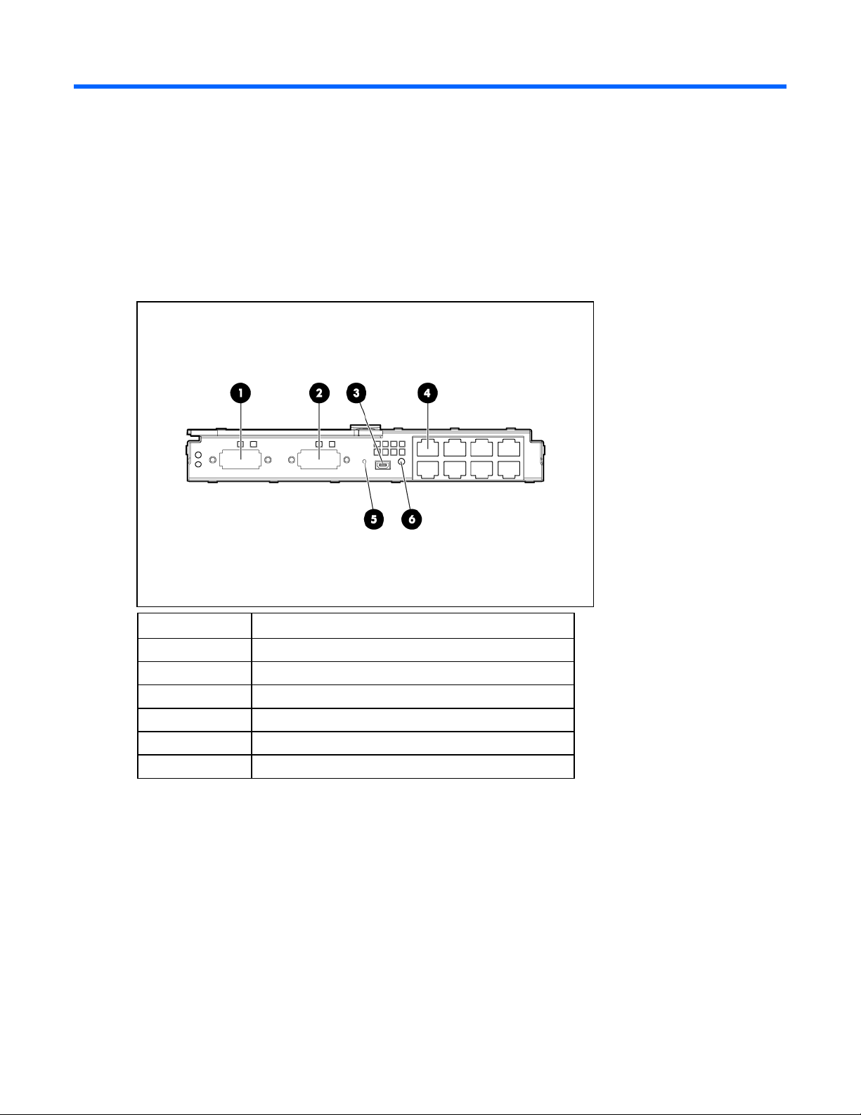
HP 1/10Gb VC-Enet Module components
Item Description
1 Port X1 (10GBASE-CX4)
2 Port X2 (10GBASE-CX4)
3 USB 2.0 connector (covered)
4 Ports 1-8 (10/100/1000BASE-T)
5 Reset button (recessed)
6 Next button
Component identification 12
Page 13
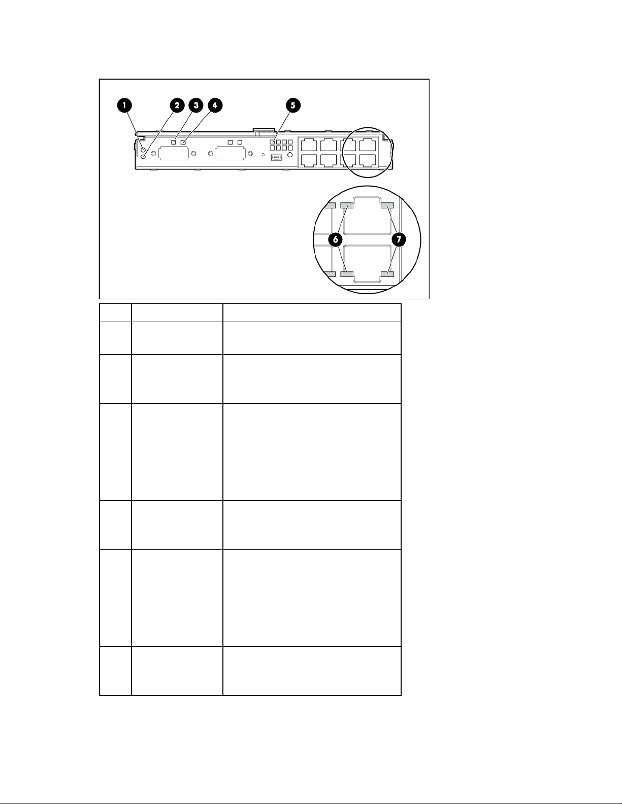
HP 1/10Gb VC-Enet Module LEDs
Item Description Status
1 Module locator (UID) Blue = Module ID is selected.
Off = Module ID is not selected.
2 Module status Green = Normal operation
Amber = Degraded condition
Off = Module powered off
3 X1/X2 port status
(10GBASE-CX4)
4 X1/X2 link/port
activity
5 Port 1-8 port status Green = Port is configured and operating
6 Port 1-8 link/activity Green = 10/100 link
Green = Port is configured and operating
as an uplink port connected to a data
center fabric.
Amber = Port is operating as a stacking
link interconnecting HP 1/10Gb VC-Enet
Modules.
Blue = Port locator (PID)
Green = Link
Green flashing = Activity
Off = No link
as an uplink port connected to a data
center fabric.
Amber = Port is operating as a stacking
link interconnecting HP 1/10Gb VC-Enet
Modules.
Blue = Port locator (PID)
Green flashing = 10/100 activity
Off = No link
Component identification 13
Page 14
Item Description Status
7 Port 1-8 link/activity Amber = 1000 link
Amber flashing = 1000 activity
Off = No link
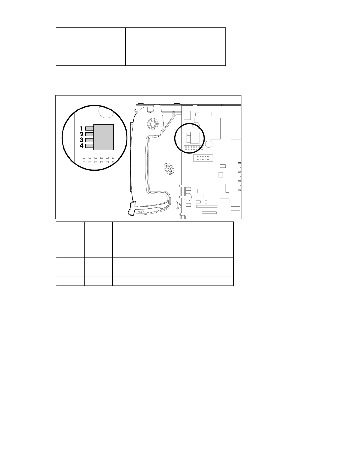
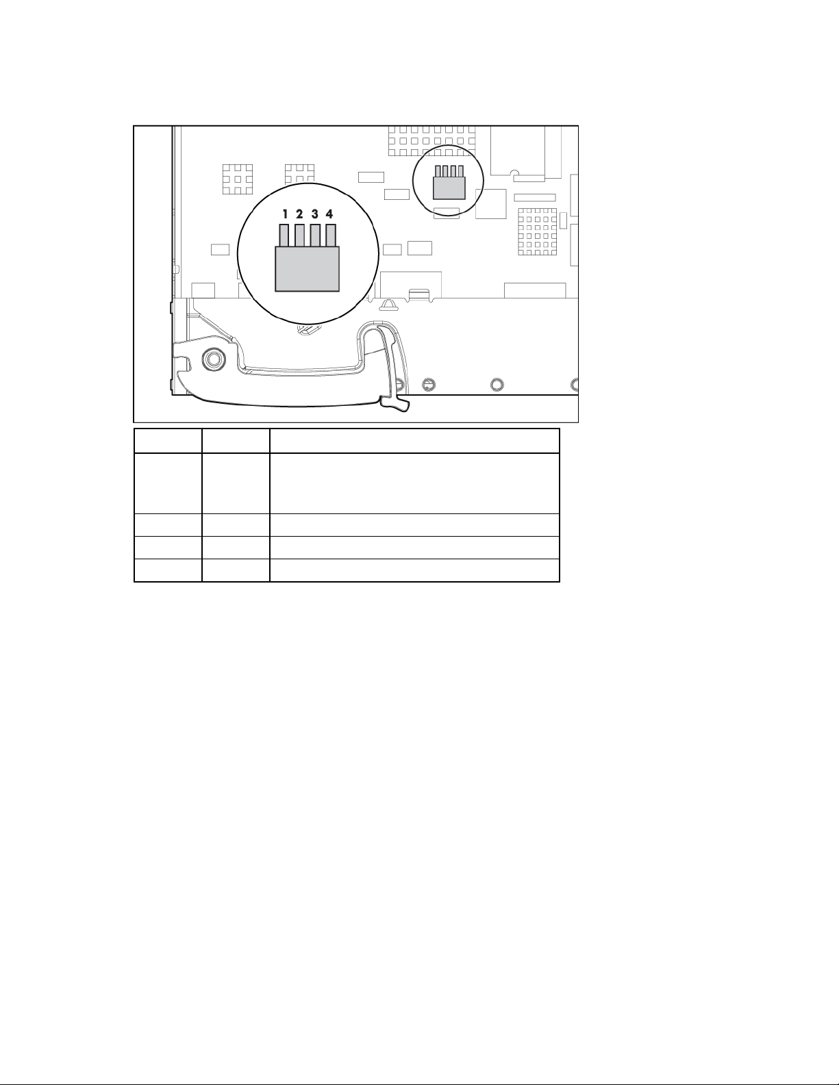
HP 1/10Gb VC-Enet Module system maintenance switch
Switch Default Function
1 Off Off = Normal operation
On = Restore factory default login and DNS
information
2 Off Reserved
3 Off Reserved
4 Off Reserved
Resetting the Administrator password and DNS settings
If the system maintenance switch 1 is in the ON position, the firmware restores the Administrator account
password and DNS settings to the original factory defaults as found on the module label (without
disturbing any other local user accounts), and also displays the password on the VC-Enet module
management console. For information on accessing the VC-Enet module management console, see the
OA user guide. The default password is no longer displayed after switch 1 is in the OFF position.
Password restoration is done during each power-up sequence while switch 1 is in the ON position (and
reserved switches are in the OFF position) and does not allow changes until the switch is placed back into
the OFF position. For switch locations, see the appropriate system maintenance switch ("HP 1/10Gb VC-
Enet Module system maintenance switch" on page 14, "HP 1/10Gb-F VC-Enet Module system
maintenance switch" on page 18).
After switch 1 is returned to the OFF position, users with appropriate privileges can then change the
Administrator password.
Component identification 14
Page 15

Only reset the password on the module running the Virtual Connect Manager (and/or its backup), and
not other modules in the domain.
The recommended password recovery procedure is as follows:
1. Remove the Virtual Connect Ethernet module from interconnect bay 1.
2. Remove the access panel from the Virtual Connect Ethernet module and set switch 1 to the ON
position. Ensure that all other switches remain in the OFF position. Install the access panel.
3. Insert the Virtual Connect Ethernet module into bay 1 and allow the module to power up and reach a
fully booted and operational state (approximately 1 minute).
4. Remove the Virtual Connect Ethernet module from interconnect bay 2.
This causes interconnect bay 1 to become the module running the active VC Manager. Because
switch 1 is set, the Administrator password remains at the factory default for interconnect bay 1 (not
overwritten by the change of state because of the failover).
5. Wait to ensure that the VC Manager has had time to become active on interconnect bay 1. Log into
the VC Manager to confirm it is up and functional on interconnect bay 1.
6. Insert the Virtual Connect Ethernet module into interconnect bay 2 and allow the module to power on
and reach a fully booted and operational state (approximately 1 minute).
7. Remove the Virtual Connect Ethernet module from interconnect bay 1.
8. Remove the access panel from the Virtual Connect Ethernet module and set switch 1 to the OFF
position. Ensure that all other switches remain in the OFF position. Install the access panel.
9. Insert the Virtual Connect Ethernet module into interconnect bay 1 and allow the module to power up
and reach a fully booted and operation state (approximately 1 minute).
10. Log into the VC Manager using the factory default user name and password to log in to the module
(regardless of whether it is running on the module in interconnect bay 1 or interconnect bay 2).
11. Change the Administrator password.
Warning messages
When a warning icon appears in the banner at the top of a page, mouse over the icon to view important
information.
Warning message: VC-Enet Module DIP switches are not configured for normal operation.
Additional information: Set the switches to the recommended configuration. See the appropriate system
maintenance switch ("HP 1/10Gb VC-Enet Module system maintenance switch" on page 14, "HP
1/10Gb-F VC-Enet Module system maintenance switch" on page 18).
Warning message: Administrator password reset switch is set.
Additional information: Set the switches to the recommended configuration. See the appropriate system
maintenance switch ("HP 1/10Gb VC-Enet Module system maintenance switch" on page 14, "HP
1/10Gb-F VC-Enet Module system maintenance switch" on page 18).
Warning message: Port monitoring is enabled.
Additional information: Port monitoring is configured and enabled within this Virtual Connect domain.
Ethernet data from the monitored ports is replicated on the network analyzer port, which poses a security
risk and could result in network loops if not properly connected. To disable or reconfigure port
monitoring, see "Ethernet Settings (Port Monitoring) screen (on page 102)."
Warning message: A firmware update is in progress.
Component identification 15
Page 16
Additional information: See "Domain Settings (Firmware Management) screen (on page 153)."
HP 1/10Gb-F VC-Enet Module components and LEDs
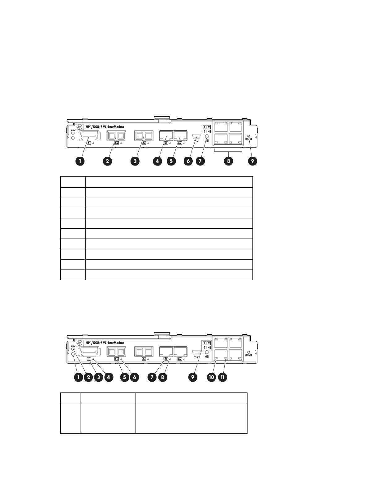
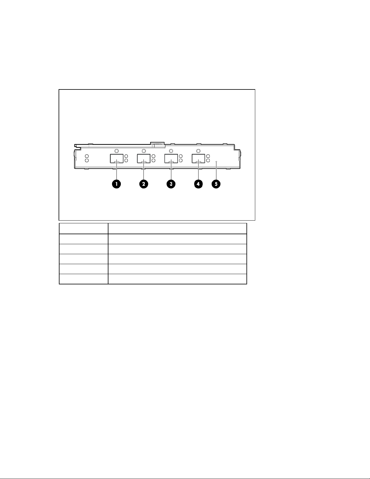
HP 1/10Gb-F VC-Enet Module components
Item Description
1 Port X1 (10GBASE-CX4)
2 Port X2 XFP connector*
3 Port X3 XFP connector*
4 Port S1 SFP connector**
5 Port S2 SFP connector**
6 USB 2.0 mini AB connector (covered)
7 Next button
8 Ports 1-4 (10/100/1000BASE-T)
9 Reset button (recessed)
* Supports 10GBASE-SR-XFP and 10GBASE-LR-XFP pluggable optical transceiver modules
** Supports 1000BASE-T-SFP and 1000BASE-SX-SFP pluggable optical transceiver modules
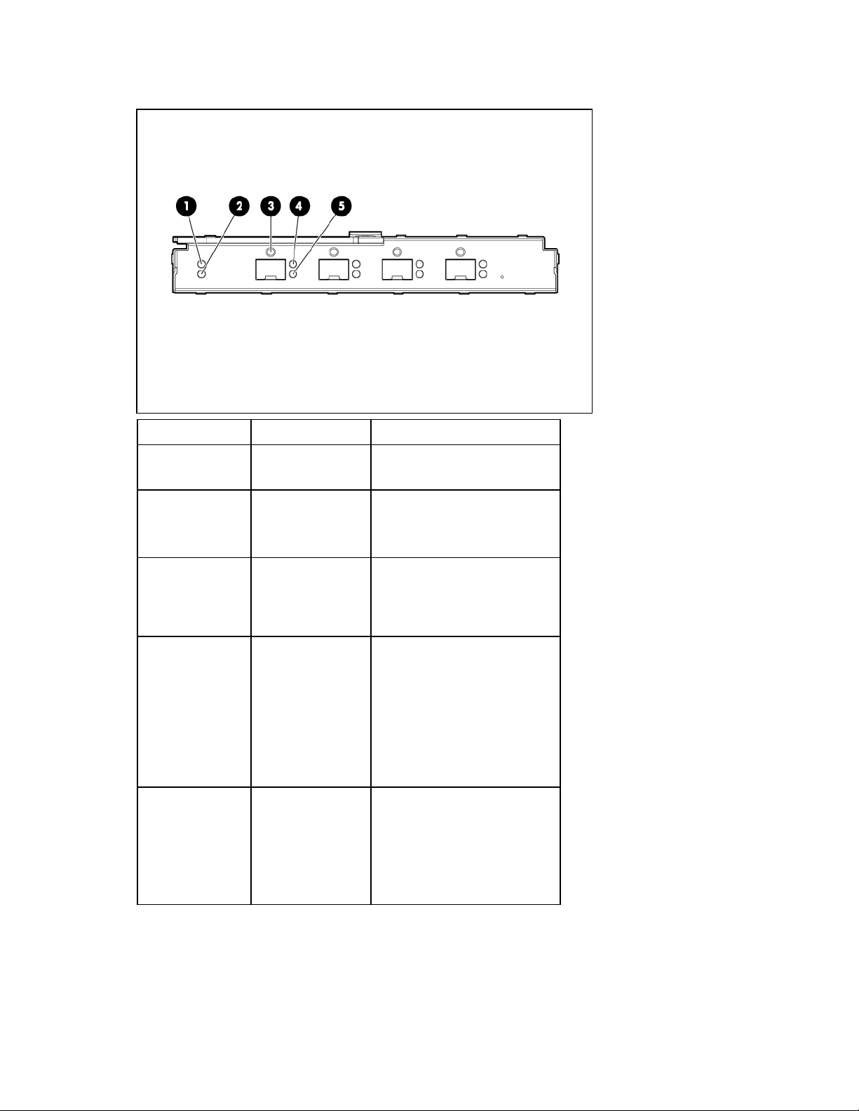
HP 1/10Gb-F VC-Enet Module LEDs
Item LED description Status
1 Module status Green = Normal operation
Amber = Degraded condition
Off = Power off
Component identification 16
Page 17

Item LED description Status
2 Module locator (UID) Blue = Module ID selected
Off = Module ID not selected
3 X1 port status
(10GBASE-CX4)
4 X1 link/port activity Green = Link
5 Port X2/X3 status Green = Port is configured and operating as
6 Port X2/X3 activity Green = Link
7 Port S1/S2 status Green = Port is configured and operating as
8 Port S1/S2 activity Green = Link
9 Port 1-4 port status Green = Port is configured and operating as
10 Port 1-4 link/activity Green = 10/100 link
11 Port 1-4 link/activity Amber = 1000 link
Green = Port is configured and operating as
an uplink port connected to a data center
fabric.
Amber = Port is operating as a stacking link
interconnecting Virtual Connect modules.
Blue = Port locator (PID)
Green flashing = Activity
Off = No link
an uplink port connected to a data center
fabric.
Amber = Port is operating as a stacking link
interconnecting Virtual Connect module.
Blue = Port locator (PID)
Green flashing = Activity
Off = No link, unsupported or absent
pluggable module
an uplink port connected to a data center
fabric.
Amber = Port is operating as a stacking link
interconnecting Virtual Connect module.
Blue = Port locator (PID)
Green flashing = Activity
Off = No link, unsupported or absent
pluggable module
an uplink port connected to a data center
fabric.
Amber = Port is operating as a stacking link
interconnecting Virtual Connect modules.
Blue = Port locator (PID)
Green flashing = 10/100 activity
Off = No link
Amber flashing = 1000 activity
Off = No link
Component identification 17
Page 18
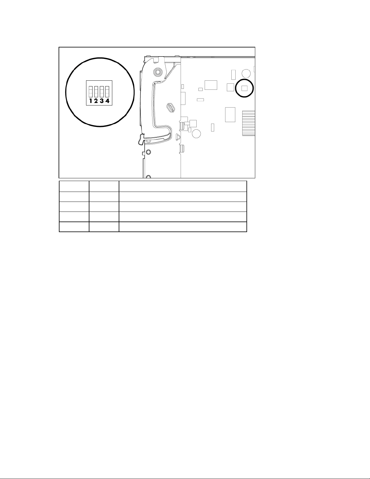
HP 1/10Gb-F VC-Enet Module system maintenance switch
Switch Default Function
1 Off Off = Normal operation
On = Restore factory default login and DNS
information*
2 Off Reserved
3 Off Reserved
4 Off Reserved
*See "Resetting the Administrator password and DNS settings (on page 14)."
Component identification 18
Page 19
HP 4Gb Fibre Channel Module components and LEDs
HP 4Gb VC-FC Module components
Item Description
1 SFP 1/2/4 Gb port 1
2 SFP 1/2/4 Gb port 2
3 SFP 1/2/4 Gb port 3
4 SFP 1/2/4 Gb port 4
5 Reset button (recessed)
In the default configuration (before a Virtual Connect domain is created), all 1/2/4 Gb capable uplink
ports are grouped into an uplink port group and dynamically distribute connectivity from all 16 server
blades.
Component identification 19
Page 20
HP 4Gb VC-FC Module LEDs
Item LED description Status
1 Module locator
(UID)
2 Module status Green = Normal operation
3 Port Green = Port is configured as
4 Logged in Green = Logged in to an
5 Activity Green flashing (variable) = Link
Blue = Module ID selected
Off = Module ID not selected
Amber = Degraded condition
Off = Power off
the uplink for one or more server
HBAs.
Blue = Port is selected.
external Fibre Channel switch
port
Green flashing = Port logging
into the fabric, port disabled, or
port failed POST at startup
Off = Port down, offline, no
sync, or error
activity
Green flashing (1 Hz) = External
fabric switch does not support
NPIV
Off = No activity
Component identification 20
Page 21
VC-FC Module system maintenance switch
Switch Default Function
1 Off Reserved
2 Off Reserved
3 Off Reserved
4 Off Reserved
When part of a Virtual Connect domain, Virtual Connect Manager overrides any system maintenance
switch settings.
Component identification 21
Page 22

Installation
Supported configurations
Versions 1.10 and higher of the Virtual Connect firmware support up to eight Virtual Connect Ethernet
modules in a single c7000 enclosure, and up to four HP 4Gb VC-FC Modules in a single c7000
enclosure. In addition, versions 1.20 and higher of the Virtual Connect firmware support up to four Virtual
Connect Ethernet modules in a single c3000 enclosure, and up to two HP 4Gb VC-FC Modules in a
single c3000 enclosure. The following configuration guidelines help identify supported configurations:
• In all Virtual Connect configurations, a Virtual Connect Ethernet module must be installed in
interconnect bay 1. The embedded Virtual Connect Manager typically runs on this module.
• To support high availability of the Virtual Connect environment, HP recommends that Virtual Connect
Ethernet modules be used in interconnect bays 1 and 2. The embedded Virtual Connect Manager
will run in an active/standby configuration. See "Failover and check-pointing (on page 41)."
• Virtual Connect Ethernet modules are typically used in pairs to provide access to all Ethernet
controllers on the server blade.
• The specific interconnect bays with Ethernet connectivity, other than bay 1 and 2, depend on
mezzanine card locations within the server blade.
• If a Virtual Connect Ethernet module is installed in an interconnect bay, the only module that can be
installed in the horizontally adjacent bay is another Virtual Connect Ethernet module.
• If an HP VC-FC module is installed in an interconnect bay, the only module that can be installed in
the horizontally adjacent bay is another VC-FC module.
• For c3000 enclosures, when two Fibre Channel mezzanine cards are installed in slots 2 and 3 of a
full-height server blade, the VC Manager only creates Fibre Channel connections and assigns
WWNs to the ports associated with the Fibre Channel mezzanine card in slot 2. This restriction does
not apply for c7000 enclosures.
IMPORTANT: To support high availability, always install Virtual Connect Ethernet modules in
interconnect bays 1 and 2.
HP BladeSystem c7000 Enclosure supported configurations
The following tables show a number of typical, supported configurations for an HP BladeSystem c7000
Enclosure.
[Bay 1] VC Ethernet [Bay 2] Empty
[Bay 3] Other/empty [Bay 4] Other/empty
[Bay 5] Other/empty [Bay 6] Other/empty
[Bay 7] Other/empty [Bay 8] Other/empty
[Bay 1] VC Ethernet [Bay 2] VC Ethernet
Installation 22
Page 23

[Bay 3] Other/empty [Bay 4] Other/empty
[Bay 5] Other/empty [Bay 6] Other/empty
[Bay 7] Other/empty [Bay 8] Other/empty
[Bay 1] VC Ethernet [Bay 2] VC Ethernet
[Bay 3] VC Ethernet [Bay 4] VC Ethernet
[Bay 5] Other/empty [Bay 6] Other/empty
[Bay 7] Other/empty [Bay 8] Other/empty
[Bay 1] VC Ethernet [Bay 2] VC Ethernet
[Bay 3] Other/empty [Bay 4] Other/empty
[Bay 5] VC Ethernet [Bay 6] VC Ethernet
[Bay 7] Empty [Bay 8] Empty
[Bay 1] VC Ethernet [Bay 2] VC Ethernet
[Bay 3] VC Ethernet [Bay 4] VC Ethernet
[Bay 5] VC Ethernet [Bay 6] VC Ethernet
[Bay 7] Empty [Bay 8] Empty
[Bay 1] VC Ethernet [Bay 2] Empty
[Bay 3] VC-FC [Bay 4] Empty
[Bay 5] Other/empty [Bay 6] Other/empty
[Bay 7] Other/empty [Bay 8] Other/empty
[Bay 1] VC Ethernet [Bay 2] VC Ethernet
[Bay 3] VC-FC [Bay 4] VC-FC
[Bay 5] Other/empty [Bay 6] Other/empty
[Bay 7] Other/empty [Bay 8] Other/empty
[Bay 1] VC Ethernet [Bay 2] VC Ethernet
[Bay 3] VC Ethernet [Bay 4] VC Ethernet
[Bay 5] VC-FC [Bay 6] VC-FC
[Bay 7] Empty [Bay 8] Empty
[Bay 1] VC Ethernet * [Bay 2] VC Ethernet
[Bay 3] VC Ethernet [Bay 4] VC Ethernet
[Bay 5] VC-FC [Bay 6] VC-FC
[Bay 7] VC-FC [Bay 8] VC-FC
* This configuration is only applicable for enclosures with full-height servers.
[Bay 1] VC Ethernet [Bay 2] VC Ethernet
[Bay 3] VC-FC [Bay 4] VC-FC
[Bay 5] VC Ethernet [Bay 6] VC Ethernet
[Bay 7] Empty [Bay 8] Empty
Installation 23
Page 24
[Bay 1] VC Ethernet [Bay 2] VC Ethernet
[Bay 3] VC-FC [Bay 4] VC-FC
[Bay 5] VC Ethernet [Bay 6] VC Ethernet
[Bay 7] VC Ethernet [Bay 8] VC Ethernet
[Bay 1] VC Ethernet [Bay 2] VC Ethernet
[Bay 3] Other/empty [Bay 4] Other/empty
[Bay 5] VC-FC [Bay 6] VC-FC
[Bay 7] Empty [Bay 8] Empty
[Bay 1] VC Ethernet [Bay 2] VC Ethernet
[Bay 3] VC-FC [Bay 4] VC-FC
[Bay 5] VC-FC [Bay 6] VC-FC
[Bay 7] Empty [Bay 8] Empty
[Bay 1] VC Ethernet [Bay 2] VC Ethernet
[Bay 3] VC Ethernet [Bay 4] VC Ethernet
[Bay 5] VC Ethernet [Bay 6] VC Ethernet
[Bay 7] VC Ethernet [Bay 8] VC Ethernet
HP BladeSystem c3000 Enclosure supported configurations
The following tables show a number of typical, supported configurations for an HP BladeSystem c3000
Enclosure.
[Bay 1] VC Ethernet [Bay 2] VC Ethernet
[Bay 3] Empty [Bay 4] Empty
[Bay 1] VC Ethernet [Bay 2] VC Ethernet
[Bay 3] VC Ethernet [Bay 4] VC Ethernet
[Bay 1] VC Ethernet [Bay 2] VC Ethernet
[Bay 3] VC-FC [Bay 4] VC-FC
Installation guidelines
Observe the following guidelines:
• To set up and configure Virtual Connect Manager, interconnect bay 1 must be populated with a
Virtual Connect Ethernet module.
• To support failover configuration for Virtual Connect Manager, install a second Virtual Connect
Ethernet module in interconnect bay 2.
• To avoid connectivity loss, do not install Virtual Connect and non-Virtual Connect modules in
interconnect bays connected to the same server blade mezzanine card.
Installation 24
Page 25

• Do not mix Virtual Connect Ethernet modules and Virtual Connect Fibre Channel modules in
interconnect bays connected to the same server blade mezzanine card because this action generates
an enclosure electronic keying error.
• For each Ethernet mezzanine port you want to manage with Virtual Connect Manager, install a
Virtual Connect Ethernet module in the interconnect bay connected to that port. For more
information, see the appropriate HP BladeSystem enclosure setup and installation guide.
• Virtual Connect assigns or migrates MAC addresses for device bay ports connected to Virtual
Connect Ethernet modules only.
• When using stacking cables to connect multiple Virtual Connect Ethernet modules or using optional
optical transceiver modules, order the cables separately. For more information, see the HP Virtual
Connect QuickSpecs on the HP website (http://www.hp.com/go/bladesystem/interconnects
).
• For web browser compatibility with Virtual Connect Manager v1.20 or higher, use Microsoft®
Internet Explorer 6.0 or higher or Mozilla Firefox 1.5 or higher. For additional information, see the
Virtual Connect Manager release notes on the HP website
(http://www.hp.com/go/bladesystem/documentation
).
• For more information on BladeSystem port mapping, see the HP BladeSystem enclosure setup and
installation guide that ships with the enclosure.
• For the most current product information, see the release notes on the HP website
(http://www.hp.com/go/bladesystem/documentation
).
• HP 4GB VC-FC Module SFP ports can be connected only to Fibre Channel switch ports that support
N_port_ID virtualization. To verify that NPIV support is provided, see the firmware documentation
that ships with the Fibre Channel switch.
• Install the HP 4Gb VC-FC Module in interconnect bays 3 or higher. Interconnect bays 1 and 2 are
reserved for Ethernet modules.
• All modules in the enclosure require a valid and unique IP address, and all modules must be on the
same subnet. Use a DHCP server or the Onboard Administrator EBIPA feature to assign each module
an IP address.
NOTE: Virtual Connect assigns and migrates MAC addresses and/or WWNs for ports
connected to Virtual Connect Ethernet modules or HP 4Gb VC-FC Modules only.
For more information on the association between the server blade mezzanine connectors and the
interconnect bays, see the HP BladeSystem enclosure setup and installation guide that ships with the
enclosure. During server blade installation, the location of the mezzanine card determines the installation
location of the interconnect modules.
For specific interconnect module port connection information for each blade, see the HP BladeSystem
enclosure setup and installation guide that ships with the enclosure. Connections differ by server blade
type.
Virtual Connect and EBIPA
Enclosure Bay IP Addressing is used to specify IP addresses for the interconnect modules, which are then
provided to the modules by the Onboard Administrator.
Because the Virtual Connect Manager communicates with other components through the Onboard
Administrator, special considerations are required when using EBIPA with Virtual Connect Ethernet
modules:
Installation 25
Page 26
• The Onboard Administrator must be on the same IP subnet as all Virtual Connect modules.
• The Onboard Administrator IP address must be set properly before changing the IP addresses of the
Virtual Connect modules.
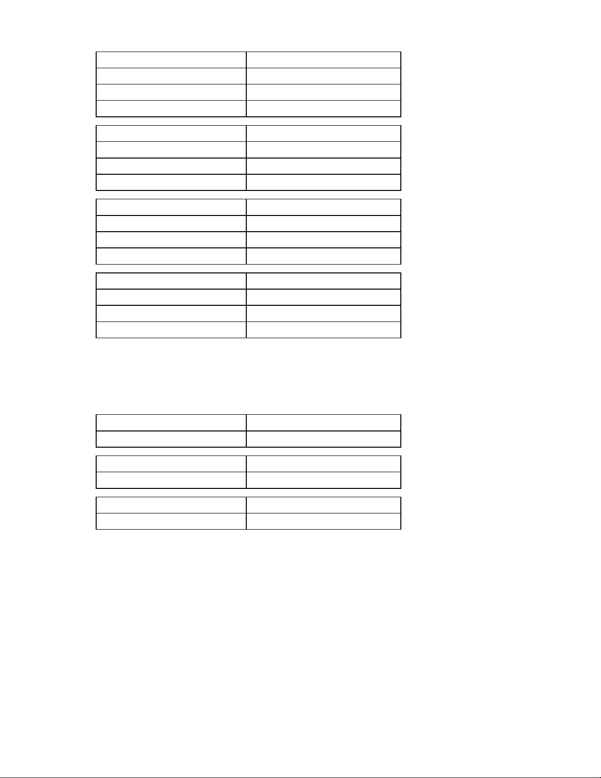
Installing the HP 1/10Gb VC-Enet Module
1. Remove the interconnect blank.
2. Prepare the HP 1/10Gb VC-Enet Module for installation.
Installation 26
Page 27
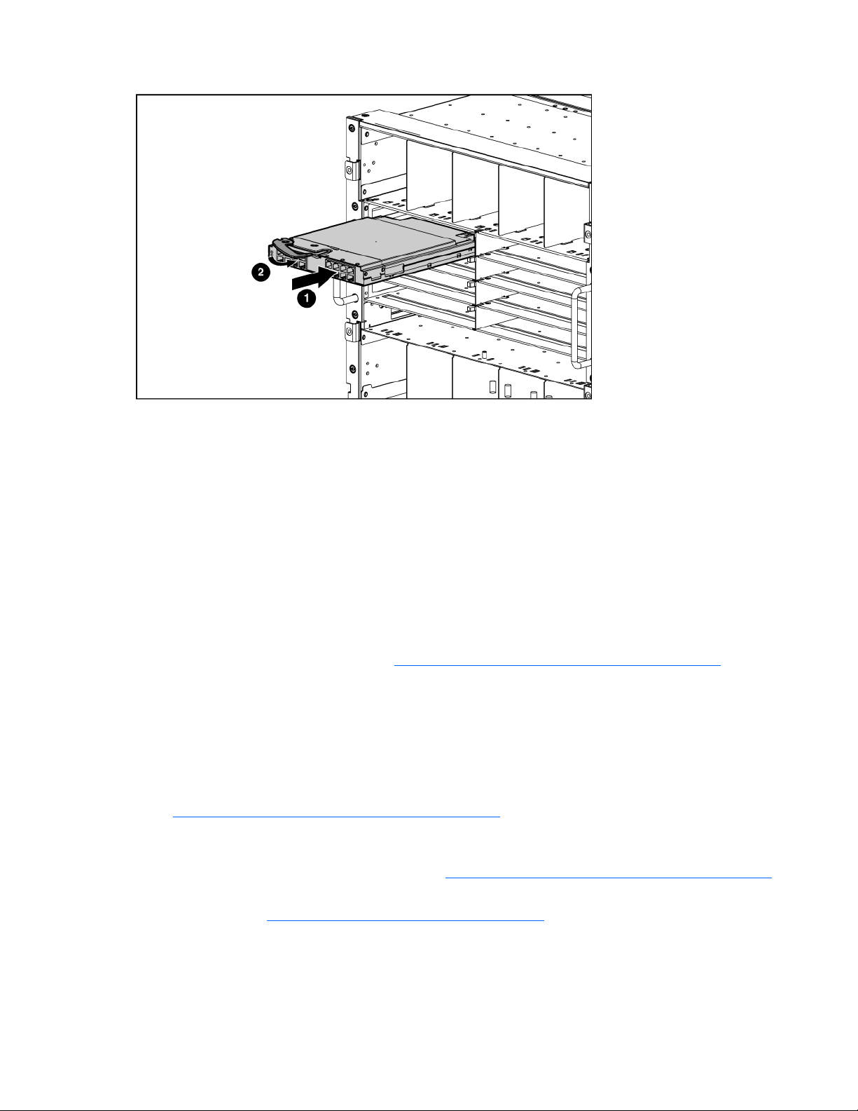
3.
Install the HP 1/10Gb VC-Enet Module into the interconnect bay.
4. If the VC Manager configuration includes three or more HP 1/10Gb VC-Enet Modules, install
stacking links (typically 10GBASE-CX4 cables) between the modules. For more information, see
"Connecting Virtual Connect Ethernet Module uplinks (on page 36)."
5. Connect the data center network cables to the HP 1/10Gb VC-Enet Module 10/100/1000BASE-T
ports or the unused 10GBASE-CX4 ports. This step can be deferred until after setup of the Virtual
Connect Manager software. See "Default module configuration (on page 10)."
6. Remove the perforated portion of the Default Network Setting label that extends beyond the
faceplate of the HP 1/10Gb VC-Enet Module installed in interconnect bay 1.
The Default Network Settings label contains the DNS name, username, and password of the
interconnect module in interconnect bay 1. This information is required for access to the HP Virtual
Connect Manager.
7. Power on and configure the enclosure. See the appropriate HP BladeSystem enclosure setup and
installation guide on the HP website (http://www.hp.com/go/bladesystem/documentation
8. Connect a workstation to the data center network hosting the HP BladeSystem Onboard
).
Administrator for the enclosure.
9. Start and log on to the workstation.
10. Open a compatible web browser.
11. Log on to the HP BladeSystem Onboard Administrator. For specific instructions, see the HP
BladeSystem Onboard Administrator User Guide on the HP website
(http://www.hp.com/go/bladesystem/documentation
12. Verify that the HP Onboard Administrator firmware is at revision 1.30 or higher. HP recommends
).
using version 2.02 or higher. For specific instructions, see the HP BladeSystem Onboard
Administrator User Guide on the HP website (http://www.hp.com/go/bladesystem/documentation
).
13. Be sure that the server blade BIOS and NIC options ROM are at the appropriate revision level. See
the HP website (http://www.hp.com/go/bladesystemupdates
14. Be sure that the HP 1/10Gb VC-Enet Module management ports can obtain IP addresses through
).
DHCP or from the Enclosure Bay IP Addresses screen within the Onboard Administrator.
15. From the Onboard Administrator enclosure overview screen, click the Virtual Connect Manager link.
Installation 27
Page 28
The Virtual Connect Manager logon screen appears.
16. Type the user name from the Default Network Settings label into the Username field.
17. Type the password from the Default Network Settings label into the Password field.
The HP Virtual Connect Manager Setup Wizard screen appears.
18. Use the VC Manager to administer the HP 1/10Gb VC-Enet Module for the enclosure.
After an enclosure is imported into a Virtual Connect domain, server blades that have not been assigned
a server profile are isolated from all networks to ensure that only properly configured servers are attached
to data center networks.
A pre-deployment server profile can be defined within the Virtual Connect Manager for each device bay
so that the server blade can be powered on and connected to a deployment network. These profiles can
then be modified at a later time or replaced by another server profile. See "Server Profiles screen (on
page 142)."
Installing the HP 1/10Gb-F VC-Enet Module
1. Remove the interconnect blank.
NOTE: HP Virtual Connect works optimally in enclosures configured with HP Virtual Connect
interconnect modules only.
Installation 28
Page 29
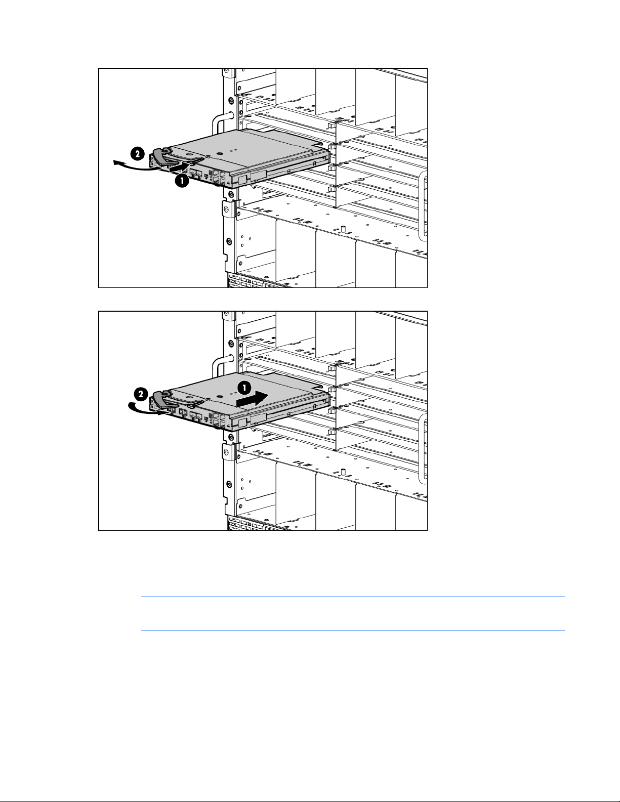
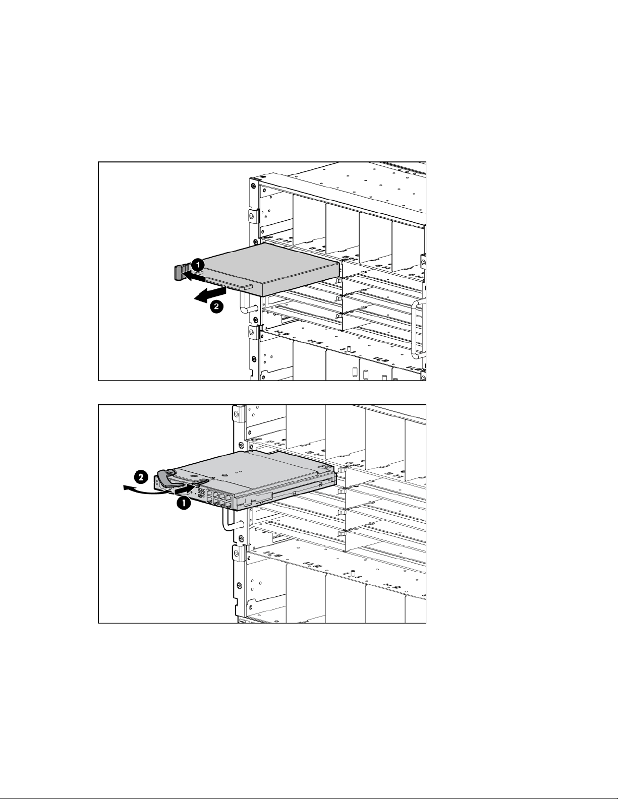
2.
Prepare the HP 1/10Gb-F VC-Enet Module for installation.
3. Install the HP 1/10Gb-F VC-Enet Module into the interconnect bay.
4. If the enclosure configuration includes more than one Virtual Connect module, stacking cables might
be needed. Connect any necessary stacking cables between the modules.
5. Connect the data center network cables to any HP 1/10Gb-F VC-Enet Module port not being used
for Virtual Connect stacking links.
NOTE: The 1000BASE-SFP and 10GBASE-XFP ports can be used to connect to the data center
if they are populated with a supported pluggable SFP or XFP optical transceiver module.
6. Remove the perforated portion of the Default Network Setting label that extends beyond the
faceplate of the Virtual Connect Ethernet module installed in interconnect bay 1.
The Default Network Settings label contains the DNS name, username, and password of the
interconnect module in interconnect bay 1. This information is required for access to the HP Virtual
Connect Manager.
Installation 29
Page 30

7.
Connect a workstation to the data center network hosting the HP BladeSystem Onboard
Administrator for the enclosure.
8. Start and log on to the workstation.
9. Open a web browser.
10. Log on to the HP BladeSystem Onboard Administrator. If prompted, follow the steps in the OA First
Time Setup Wizard. For specific instructions, see the HP BladeSystem Onboard Administrator User
Guide on the HP website (http://www.hp.com/go/bladesystem/documentation
11. Before accessing the Virtual Connect Manager, verify that the HP BladeSystem Onboard
).
Administrator firmware is at revision 2.0 or later. For specific instructions, see the HP website
(http://www.hp.com/go/bladesystemupdates
IMPORTANT: For proper Virtual Connect operation, always assign an IP address to each
).
server blade iLO and interconnect module.
12. Verify that each server blade iLO and interconnect module has been assigned an IP address by
reviewing the bay summary screens in Onboard Administrator. Each IP address must be valid and
unique, and all iLOs and Virtual Connect modules must be on the same subnet. For more
information, see the HP BladeSystem Onboard Administrator User Guide on the HP website
(http://www.hp.com/go/bladesystem/documentation
13. From the enclosure overview screen, click Virtual Connect Manager.
).
The Virtual Connect Manager logon screen appears.
14. In the Username field, type Administrator.
15. Enter the password from the Default Network Settings label into the Password field.
The HP Virtual Connect Manager Setup Wizard screen appears.
16. Use the VC Manager to administer the HP 1/10Gb-F VC-Enet Module for the enclosure.
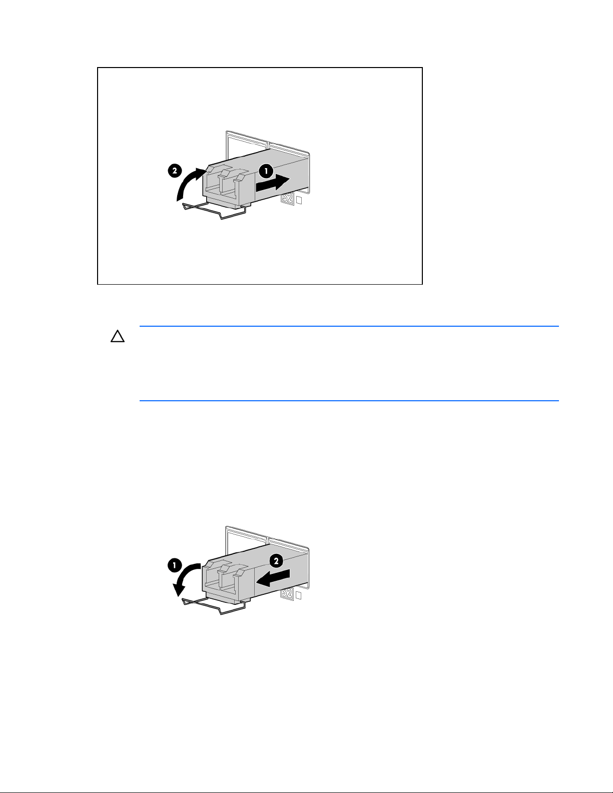
Installing SFP transceivers
CAUTION: Disconnect all cables before removing or installing an SFP transceiver, because of
the potential damage to the cables, the cable connector, or the optical interfaces in the SFP
transceiver.
Removing and installing an SFP transceiver can shorten the useful life. Do not remove and
1. Remove the dust cap and save it for future use.
insert SFP transceivers more often than is necessary.
CAUTION: Do not remove the dust plugs from the fiber-optic SFP transceiver or the rubber
plugs from the fiber-optic cable until you are ready to connect the cable. The plugs and caps
protect the SFP transceiver ports and cables from contamination and ambient light.
IMPORTANT: Use only SFP transceivers purchased from HP.
2. Install the SFP transceiver with the label side up.
Installation 30
Page 31
Ensure that the latch is closed and that the transceiver is fully seated.
Removing SFP transceivers
CAUTION: Disconnect all cables before removing or installing an SFP transceiver, because of
the potential damage to the cables, the cable connector, or the optical interfaces in the SFP
transceiver.
Removing and installing an SFP transceiver can shorten the useful life. Do not remove and
1. Disconnect all cables.
2. Open the latch.
3. Remove the SFP transceiver.
insert SFP transceivers more often than is necessary.
4. Install dust plugs on the fiber-optic SFP transceiver and rubber plugs on the fiber-optic cable.
Installation 31
Page 32

CAUTION: Be sure to install the dust plugs on the fiber-optic SFP transceiver and the rubber
plugs on the fiber-optic cable. The plugs and caps protect the SFP transceiver ports and cables
from contamination and ambient light.
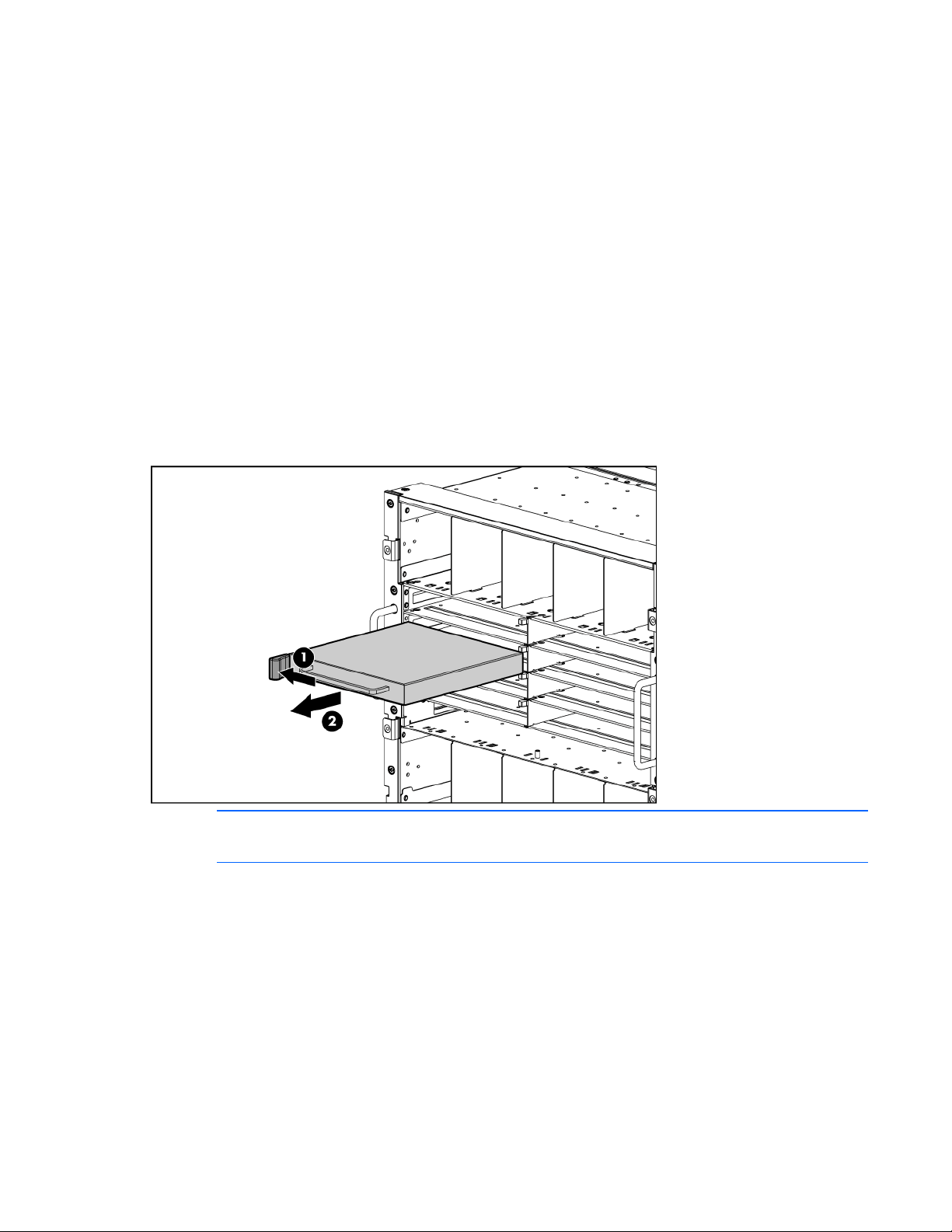
Installing the HP 4Gb Virtual Connect Fibre Channel Module
1. Remove the interconnect blank.
NOTE: HP Virtual Connect works optimally in enclosures configured with HP Virtual Connect
interconnect modules only.
2. Prepare the HP 4Gb Virtual Connect Fibre Channel Module for installation.
Installation 32
Page 33

3.
Install the HP 4Gb Virtual Connect Fibre Channel Module into the interconnect bay.
4. Connect the data center SAN switch ports to the VC-FC module 1/2/4 Gb SFP ports.
5. Configure the VC-FC module:
o If VC-Enet modules are installed in the same enclosure, use the Virtual Connect Manager to
administer VC-FC modules.
o If VC-Enet modules are not installed in the same enclosure, the VC-FC module operates in the
default configuration only. For more information, see "HP 4Gb VC-FC Module components (on
page 19)."
6. Be sure that the HP 4Gb VC-FC Module management ports can obtain IP addresses through DHCP
or from the Enclosure Bay IP Addresses screen within the Onboard Administrator.
Factory default settings
The Virtual Connect Delete Domain operation ("Deleting a domain" on page 151) returns all VC-FC
modules to the factory default settings.
VC-FC modules that are physically removed from a VC domain can be returned to the factory default
settings when placed into a new enclosure by applying power, and then pressing and holding the reset
button on the front panel for at least 10 seconds. When moved from a VC domain and placed into an
enclosure not part of a VC domain, VC-FC modules retain assigned mappings until reset to the factory
default.
Firmware requirements
IMPORTANT: HP recommends that all VC-Enet modules in the domain are at the same revision
level. Some versions of the Virtual Connect firmware might not be compatible. The active
Virtual Connect Manager does not allow incompatible modules to be managed as part of the
Virtual Connect domain.
IMPORTANT: For optimal operation of HP Virtual Connect Manager, use the recommended
firmware versions.
Installation 33
Page 34

Install the recommended firmware for the following items:
• Server blade system ROMs
• Ethernet mezzanines
• Fibre Channel mezzanines
• HP BladeSystem Onboard Administrator
For additional information on recommended firmware versions and to download firmware upgrades, see
the HP website (http://www.hp.com/go/bladesystemupdates
).
Recommended stacking connections
Stacking links are used to interconnect Virtual Connect Ethernet modules when more than two Virtual
Connect Ethernet modules are installed in a single enclosure. This feature enables all Ethernet network
controllers on all servers in the Virtual Connect domain to have access to any Virtual Connect Ethernet
module uplink port. By using these module-to-module links, a single pair of uplinks can function as the
data center network connections for the entire Virtual Connect domain. Stacking enables any server NIC
physically connected to a VC module to be connected to any Ethernet network.
Each interconnect module has several numbered Ethernet connectors. All of these connectors can be used
to connect to data center switches or they can be used to stack Virtual Connect modules and enclosures.
Virtual Connect automatically detects when one Virtual Connect Ethernet module port is connected to
another Virtual Connect Ethernet module port within the domain and turns the port ID indicator amber.
All Virtual Connect Ethernet modules within the Virtual Connect Domain must be interconnected. Any
combination of 1-Gb and 10-Gb cables can be used to interconnect the Virtual Connect Ethernet modules.
However, the following illustration provides recommended configurations for two, four, six, or eight
Virtual Connect Ethernet modules. A 10-Gb stacking link is already provided on the enclosure midplane
for horizontally adjacent Virtual Connect Ethernet modules (bays 1 and 2, 3 and 4, 5 and 6, or 7 and 8
of the c7000 enclosure, or bays 1 and 2, or 3 and 4 of the c3000 enclosure).
NOTE: Port X0 is the 10Gb port connected through the midplane of horizontally-adjacent
Virtual Connect Ethernet modules, and it appears in the list of stacking link connections within
the user interface.
Installation 34
Page 35

Virtual Connect Ethernet modules support 10GBASE-CX4 stacking cables 0.5 m to 7 m (1.64 ft to 23.00
ft). The 1000BASE-T links can also be used as stacking links of up to 100 m (328 ft). When multiple
cables of either the same or dissimilar type (for example 1Gb and 10Gb) are connected to the same two
modules, they are aggregated to provide enhanced throughput for the stacking link.
NOTE: The CX4 interface uses the same physical connector as Infiniband, but Infiniband
cables are tuned differently and will not perform as well in CX4 applications. HP recommends
purchasing CX4 cable assemblies that meet the IEEE CX4 specifications and support 10Gigabit communication at distances from 3 m to 15 m (9.84 ft to 49.20 ft).
Fully redundant interconnection of Virtual Connect Ethernet modules is recommended. The recommended
stacking configurations have redundant connections. If a stacking cable is lost, the Ethernet packets within
the Virtual Connect domain are automatically re-routed to the uplink through the redundant path. This
configuration also helps preserve network connectivity if an Ethernet interconnect module fails or is
removed. Due to the reliability of the midplane connection between horizontally-adjacent Virtual Connect
Ethernet modules, external stacking cables are not needed in configurations with two Virtual Connect
Ethernet modules in interconnect bays 1 and 2.
Installation 35
Page 36

Loop prevention
When link is established on a Virtual Connect Ethernet module port, the port exchanges LLDP packets with
the far-side connection. This LLDP protocol is an IEEE 802.1 standard that makes use of special BPDU
packets that are not forwarded by Ethernet bridges or switches. As part of the LLDP exchange, Virtual
Connect can determine whether a Virtual Connect Ethernet module port is connected to another port
within the same Virtual Connect domain. If the port is connected, the port is designated as a stacking link
and treated as such. If the port is not connected, then the port is available for use as an uplink port.
Only ports that have not been designated as an uplink port in a network are eligible to become stacking
links. If a port has been designated as an uplink port, and then is subsequently connected to another
Virtual Connect Ethernet module, the port will not become a stacking link until it is removed from the
network definition as an uplink port.
To avoid network loops, Virtual Connect must first verify that only one active uplink exists per network
from the Virtual Connect domain to the external Ethernet switching environment. Second, Virtual Connect
must be sure that no network loops are created by the stacking links between Virtual Connect modules.
• One active link—A VC uplink set can include multiple uplink ports. To prevent a loop with broadcast
traffic coming in one uplink and going out another, only one uplink or uplink LAG is active at a time.
The uplink or LAG with the greatest bandwidth should be selected as the active uplink. If the active
uplink loses link, then the next best uplink will be made active.
• No loops through stacking links—If multiple Virtual Connect Ethernet modules are used, they are
interconnected via stacking links, which might appear as an opportunity for loops within the VC
environment. For each individual network in the Virtual Connect environment, VC will block certain
stacking links to ensure that each network has a loop-free tree. The root of this tree is usually the
module with the network uplink to the data center.
The loop avoidance feature can not be disabled or changed. However, the preferred uplink connection
for a network can be identified when defining network uplinks.
Connecting Virtual Connect Ethernet module uplinks
Each interconnect module has several numbered Ethernet connectors. All of these connectors can be used
to connect to data center switches (uplink ports) or they can be used to stack Virtual Connect modules and
enclosures as part of a single Virtual Connect domain (stacking ports). See "Recommended stacking
connections (on page 34)."
Networks must be defined within the Virtual Connect Manager so that specific, named networks can be
associated with specific external data center connections. See "Define Ethernet Network screen (on page
94)." These named networks can then be used to specify networking connectivity for individual servers.
See "Ethernet Networks (Server Connections) screen (on page 100)."
The following sections provide an overview of the types of external connections and their behaviors.
Mapping individual networks to individual external uplink ports
The simplest approach to connecting the defined networks to the data center is to map each network to a
specific external uplink port. This uplink port is defined by the following:
• Enclosure name
• Interconnect bay containing the Virtual Connect Ethernet module
Installation 36
Page 37

• Selected port on that module (1-8, X1, or X2)
Port status indicators can be used to locate a specific port or to provide additional status.
Following is an example of simple network mapping, where the Virtual Connect enclosure is named
Enclosure1 and Virtual Connect Ethernet modules are in interconnect module bays 1 and 2.
Network Uplink port
Production_Network Enclosure1:Bay1:PortX2
Dev_Network Enclosure1:Bay1:Port4
Backup_Network Enclosure1:Bay2:Port3
iSCSI_Storage_Network Enclosure1:Bay2:PortX2
In this case, the Ethernet packets are passed unchanged between the server blades and the external
networks. Any VLAN tags added by the server or external switch are ignored and pass through the Virtual
Connect Ethernet modules.
Mapping a single network to multiple uplinks (uplink port set)
A single network can be mapped to more than one external uplink port to provide improved throughput
and availability, referred to as an uplink port set. Review the following guidelines before mapping a
single network to an uplink port set:
• External uplink ports within an uplink port set can be on the same Virtual Connect Ethernet module or
on multiple Virtual Connect Ethernet modules within the Virtual Connect domain.
• Cables can be connected to one or more data center Ethernet switches.
• When multiple external uplink ports are used for the same network, the Virtual Connect Ethernet
modules provide automatic loop prevention by allowing for a single active link or link set at any one
time.
• The Virtual Connect system automatically chooses the uplink (ports) that optimize throughput and
availability. Where possible, links within the uplink port set automatically form a link aggregation
group using LACP. This action requires multiple uplink ports on a single Virtual Connect Ethernet
module to be connected to an external switch that is capable and configured to form link
aggregation groups using LACP.
Installation 37
Page 38

Following is an example of a single network mapped to four external uplink ports.
Network Uplink port set
Production_Network = { Enclosure1:Bay1:Port1
Enclosure1:Bay1:Port2
Enclosure1:Bay2:Port1
Enclosure1:Bay2:Port2 }
In this example, the ports from Bay 1 could be connected to one external switch, and the ports on Bay 2
could be connected to a second switch. If the external switches support link aggregation, then this
configuration would provide an active 2-Gb link to one switch and a standby 2-Gb link to the other.
To make Virtual Connect Manager aware of individual network connections, see "Define Ethernet
Network screen (on page 94)."
Mapping multiple networks to a single, shared external uplink port
The network administrator can choose to reduce the number of cables between the Virtual Connect
enclosure and the data center switches by mapping multiple networks to a single, shared uplink port. In
this case, a network is not just mapped to an uplink port, but to a VLAN on that port. This configuration
requires VLAN tags to be added to each packet as it leaves the Virtual Connect domain and that packets
entering the Virtual Connect domain be tagged (the VLAN tag is stripped from packets entering the Virtual
Connect domain before they are routed to the appropriate server).
NOTE: Native VLANs are not supported in version 1.10 of Virtual Connect Manager, so all
traffic must be tagged.
Following is an example of an uplink port being defined as a shared uplink port so that it can then be
used as the external connection for multiple networks.
Shared_Uplink_Port_A = Enclosure1:Bay1:PortX2
Network Shared uplink port and VLAN
Production_Network Shared_Uplink_Port_A:VLAN_15
Dev_Network Shared_Uplink_Port_A:VLAN_21
Installation 38
Page 39

Network Shared uplink port and VLAN
Backup_Network Shared_Uplink_Port_A:VLAN_32
iSCSI_Storage_Network Shared_Uplink_Port_A:VLAN_76
Because appropriate VLAN tags are added as the packets leave the enclosure, this type of uplink should
not be used in cases where VLAN tags are already added on the server itself. The system drops any
Ethernet packets with server-inserted VLAN tags that are received on networks connected to shared uplink
ports.
Mapping multiple networks to a shared uplink port set
It is also possible to map multiple VLAN-tagged networks to a set of shared uplink ports. The resulting
shared uplink port set allows for the minimum number of cables while still providing for link aggregation
and failover.
In the following example, a shared uplink port set is first defined to provide aggregation and failover.
Shared_Uplink_Set_A = {Enclosure1:Bay1:PortX2, Enclosure1:Bay2:PortX2}
Network Shared uplink port set and VLAN
Production_Network Shared_Uplink_Set_A:VLAN_15
Dev_Network Shared_Uplink_Set_A:VLAN_21
Backup_Network Shared_Uplink_Set_A:VLAN_32
iSCSI_Storage_Network Shared_Uplink_Set_A:VLAN_76
In this example, all of the defined networks share a single active uplink port (such as
Enclosure1:Bay1:Port2) using VLAN tagging, while the second link in the shared uplink port set is
available for failover. The shared uplink port set can also be constructed of multiple 1-Gb external ports.
NOTE: One network can be designated as a native VLAN, causing all untagged incoming
Ethernet packets to be placed on this network. For additional information, see "Shared uplink
sets and VLAN tagging (on page 110)."
To make Virtual Connect Manager aware of shared network connections, see "Define a Shared Uplink
Set screen ("Define New Shared Uplink Set screen" on page 110)."
Configuration example using a Cisco Core switch
There are several ways to implement a redundant Virtual Connect configuration. This example acts as a
reference for anyone who is not familiar with switch configurations. This example is just one of several
ways to connect an HP Virtual Connect to a Cisco Core switch.
Connecting Virtual Connect to a Cisco Core/distribution switch using a shared uplink set and VLAN
tagging done at the VC/data center boundary
Installation 39
Page 40

In the example below LACP is used on the Cisco Switch to connect to a shared uplink set using three
uplink ports. VLANs 10, 20, 30, and 40 from the network are tagged on the three shared uplink ports.
NOTE: Change Channel Mode to LACP on the Cisco switch.
By default, all ports on a Catalyst 4500/4000 switch and a Catalyst 6500/6000 switch use channel
protocol PAgP and as such are not running LACP. For all ports concerned, you must change the channel
mode to LACP.
On switches running CatOS, you can only change channel mode per module. In the following example,
channel mode for slots 1 and 2 are changed using the following command:
set channelprotocol lacp module_number
The changes can be verified by using the following command:
show channelprotocol.
CatOSSwitch (enable) set channelprotocol lacp 1
Mod 1 is set to LACP protocol.
CatOSSwitch (enable) set channelprotocol lacp 2
Mod 2 is set to LACP protocol.
CatOSSwitch (enable) show channelprotocol
Channel
Module Protocol
------- -------1 LACP
2 LACP
3 PAGP
5 PAGP
On switches running Cisco IOS Software specify which interfaces should be using LACP by entering the
following interface configuration command:
channel-protocol lacp:
CiscoIOSSwitch(config-if)#channel-protocol lacp
Example switch configuration of a Cat 6500 switch using IOS. (Ports 7/46, 7/47, and 7/48 on the Cat
6500 switch are used to uplink to the Virtual Connect module):
interface Port-channel10
Installation 40
Page 41

switchport
switchport trunk encapsulation dot1q
switchport trunk allowed vlan 10,20,30,40
switchport mode trunk
no ip address
interface GigabitEthernet7/46
description test-VC
switchport
switchport trunk encapsulation dot1q
switchport trunk allowed vlan 10,20,30,40
switchport mode trunk
no ip address
speed 1000
channel-protocol lacp
channel-group 10 mode active
!
interface GigabitEthernet7/47
description test-VC
switchport
switchport trunk encapsulation dot1q
switchport trunk allowed vlan 10,20,30,40
switchport mode trunk
no ip address
speed 1000
channel-protocol lacp
channel-group 10 mode active
!
interface GigabitEthernet7/48
description test-VC
switchport
switchport trunk encapsulation dot1q
switchport trunk allowed vlan 10,20,30,40
switchport mode trunk
no ip address
speed 1000
channel-protocol lacp
channel-group 10 mode active
Failover and check-pointing
Virtual Connect Manager runs as a high-availability pair when Virtual Connect Ethernet modules are
installed in interconnect bay 1 and interconnect bay 2. The active VC Manager is usually on interconnect
bay 1 at power up.
IMPORTANT: To support high availability, always install Virtual Connect Ethernet modules in
If you are not using dynamic DNS, use the Onboard Administrator to access the Virtual Connect Ethernet
module in bay 1. Then, you can optionally set a Virtual Connect Domain IP address so that you have a
consistent IP address to access VC Manager whether it is running from bay 1 or from bay 2 because of a
failover.
Each time a configuration is changed, it is written to local flash memory and then check-pointed to the
standby module. Configurations can also be backed up to a workstation using the GUI.
interconnect bays 1 and 2.
Installation 41
Page 42

NOTE: HP recommends saving a configuration after each session and before updating
firmware.
Installation 42
Page 43

HP Virtual Connect Manager
Configuring browser support
Access to the application must be through HTTPS (HTTP exchanged over an SSL-encrypted session).
For optimal viewing, HP recommends setting the screen resolution to 1280 x 1024.
Requirements
The HP Virtual Connect Manager Web interface requires an XSLT enabled browser with support for
JavaScript 1.3 or equivalent.
The following browsers are supported:
• Microsoft® Internet Explorer 6.0 or later
• Mozilla Firefox 1.5 or later
If you received a notice that your browser does not have the required functionality, examine your browser
settings to see if they meet the requirements below or contact your administrator.
The following browser settings must be enabled before running the application:
Javascript
Client-side javascript is used extensively by this application. Check the browser settings to make sure
javascript is enabled before running the application.
ActiveX
When using Microsoft® Internet Explorer with this application, ActiveX must be enabled. Check the
browser settings to make sure ActiveX is enabled before running the application.
Pop-up Windows
Pop-up windows must be allowed for certain features to function correctly. Check the browser settings to
make sure pop-up blockers are not enabled before running the application.
Cookies
Cookies must be enabled for certain features to function correctly. Check your browser settings to make
sure cookies are enabled before running the application.
If a notice is received that the browser does not have the required functionality, verify that the browser
settings meet the preceding requirements.
Virtual Connect and RDP
If you plan on using VC-assigned MAC addresses and WWNs and are also working with server software
that will be licensed by MAC addresses or WWNs, assign server profiles before deploying an image
through RDP or attaching the license.
HP Virtual Connect Manager 43
Page 44

IMPORTANT: If you plan to use RDP for RedHat Linux installation and also plan to use User- or
HP-defined MAC addresses, you must import the enclosure before running RDP.
Accessing HP Virtual Connect Manager
Access to the Virtual Connect Manager is over the same Ethernet connection used to access the enclosure
Onboard Administrator and server blade iLO connections.
There are four ways to access HP Virtual Connect Manager:
• If running dynamic DNS on the management network, locate the Default Network Settings label on
the module in interconnect bay 1 and type the DNS name into the address field of the web browser.
If you are not running dynamic DNS, use the Onboard Administrator to access the Virtual Connect
Manager.
• Log on to the enclosure Onboard Administrator. From the enclosure overview screen, select the
Virtual Connect Manager link from the left navigation window. The Onboard Administrator firmware
must be version 2.04 or later.
• Log on to the enclosure Onboard Administrator. Select Interconnect Bays in the left navigation
window of the Onboard Administrator user interface to display the Interconnect Bays summary
screen. Select the Management URL link for the Virtual Connect Ethernet module in bay 1.
The Virtual Connect Manager typically runs on the Virtual Connect Ethernet module in bay 1 unless
that module becomes unavailable, causing a failover to the Virtual Connect Manager running in bay
2. If you cannot connect to the Virtual Connect Manager in bay 1, try connecting to the management
URL for bay 2.
• Access the Virtual Connect Manager CLI remotely through an SSH session.
Command line overview
The CLI can be used as an alternative method for managing the Virtual Connect Manager. Using the CLI
can be useful in the following scenarios:
HP Virtual Connect Manager 44
Page 45
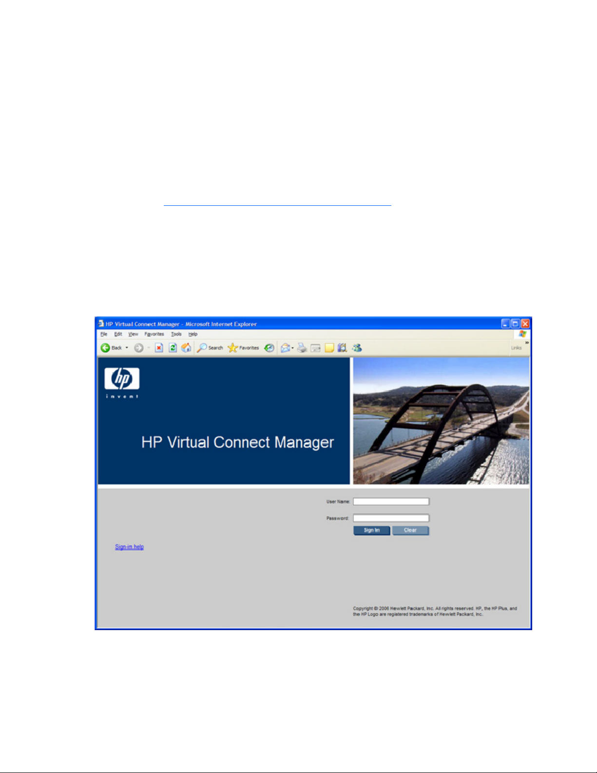
• HP Management Applications (for example: Systems Insight Manager or Insight Control tools) can
query the Virtual Connect Manager for information these tools need to present a complete
management view of HP BladeSystem enclosures and the devices contained within. This interface is
also used by the Management tools to execute provisioning and configuration tasks to devices within
the enclosure.
• Users can develop tools that utilize Virtual Connect Manager functions for data collection and for
executing provisioning and configuration tasks.
• When no browser is available or you prefer to use a command line interface, you can access
management data and perform configuration tasks.
For additional information, see the HP Virtual Connect Manager Command Line Interface User Guide on
the HP website (http://www.hp.com/go/bladesystem/documentation
).
Logging on to the HP Virtual Connect Manager GUI
Log on using the user name (Administrator) and password from the Default Network Settings label for
interconnect bay 1.
If the default network settings have been changed and need to be restored, see "Resetting the
Administrator password and DNS settings (on page 14)."
Possible causes for log on problems:
• The information is not being entered correctly. Passwords are case-sensitive.
• The account being entered is not an account for HP Virtual Connect Manager.
HP Virtual Connect Manager 45
Page 46
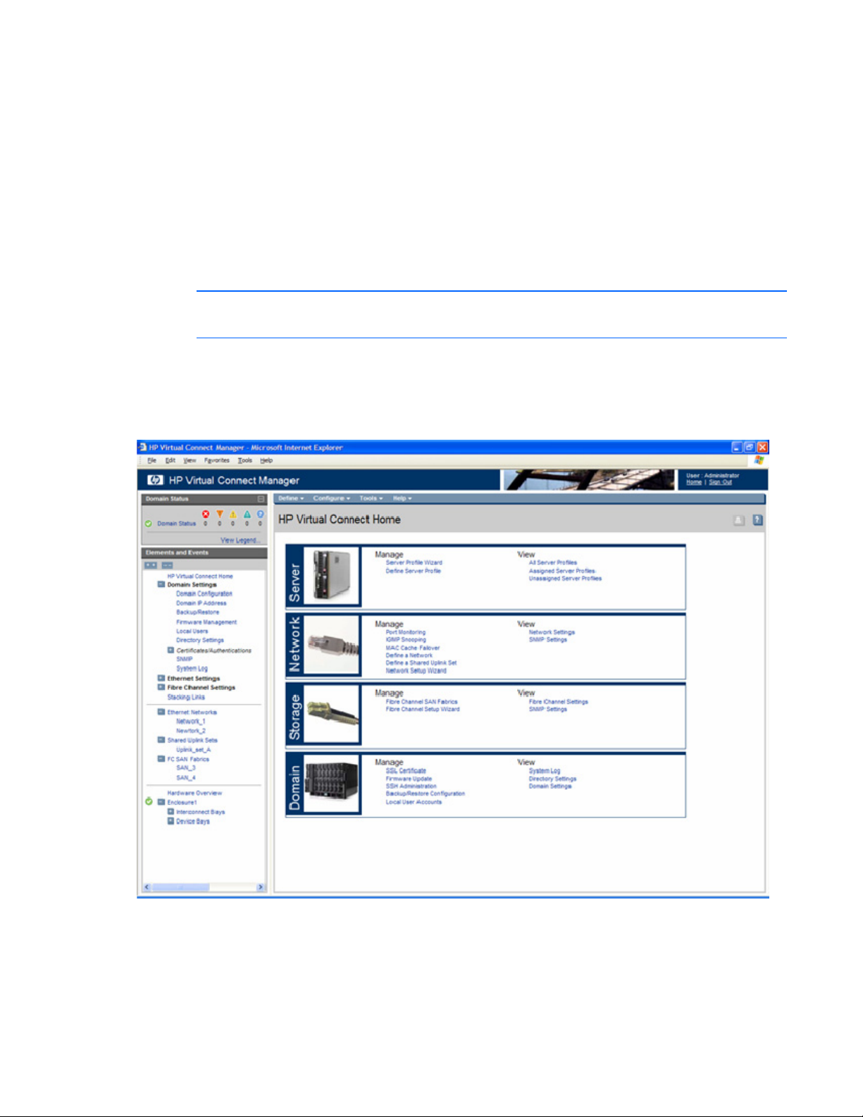
• The account being entered has been deleted, disabled, or locked out.
• The password for the account needs to be changed.
• There is no connection to the Virtual Connect Ethernet module running the active Virtual Connect
Manager.
• The Virtual Connect Manager is in the middle of a failover or recovery.
• The attempted IP sign-in address is not valid for the specified account.
• The attempted IP sign-in address is for a Virtual Connect Ethernet module not running the active
Virtual Connect Manager.
• The browser settings are incorrect. See "Configuring browser support (on page 43)."
NOTE: Virtual Connect Manager supports only one user logged in at a time.
HP Virtual Connect Home
This screen provides access for the management of enclosures, servers, networking, and storage.
About HP Virtual Connect Manager
To view detailed product information, select About HP Virtual Connect Manager from the Help pull-down
menu.
HP Virtual Connect Manager 46
Page 47

Navigating the HP Virtual Connect Manager GUI
Navigation overview
The HP Virtual Connect Manager navigation system consists of a tree view on the left side of the page that
lists all of the system devices and available actions. The tree view remains visible at all times.
The right side of the page, which includes a pull-down menu at the top, displays details for the selected
device or activity.
Menu item Links to
Define
Ethernet Network Define Ethernet Network screen (on page
94)
Shared Uplink Set Define New Shared Uplink Set screen (on
page 110)
Server Profile Define Server Profile screen (on page
131)
Configure
Domain Settings Domain Settings (Domain Configuration)
screen (on page 150)
Ethernet Network Settings Ethernet Settings (MAC Addresses) screen
(on page 101)
Fibre Channel Settings Fibre Channel Settings (FC SAN Settings)
screen (on page 126)
Local User Accounts Domain Settings (Local Users) screen (on
page 155)
Firmware Update Domain Settings (Firmware Management)
screen (on page 153)
Certificate Administration Certificates/Authentications (SSL
Certificate) screen (on page 171)
Tools
Hardware Overview Enclosures View (on page 52)
Firmware Update Domain Settings (Firmware Management)
screen (on page 153)
Domain Setup Wizard Welcome screen for the Domain Setup
Wizard ("HP Virtual Connect Domain
Setup Wizard" on page 56)
Network Setup Wizard Welcome screen for the Network Setup
Wizard ("HP Virtual Connect Network
Setup Wizard" on page 67)
Fibre Channel Setup Wizard Welcome screen for the Fibre Channel
Setup Wizard ("HP Virtual Connect Fibre
Channel Setup Wizard" on page 76)
Server Profile Wizard Welcome screen for the Server Profile
Wizard ("Virtual Connect Manager
Server Profile Wizard" on page 82)
HP Virtual Connect Manager 47
Page 48

Menu item Links to
Backup/Restore Domain
Configuration
System Log System Log screen (on page 54)
Export Support Information Support log ("Export support information"
Reset Virtual Connect Manager Reset Virtual Connect Manager screen
Help
Table of contents VC Manager help file table of contents
Index VC Manager help file index
For This Page Help topic specific to the current page
Virtual Connect Documentation on
hp.com
About HP Virtual Connect Manager Specific information about this Virtual
Domain Settings (Backup/Restore) screen
(on page 152)
on page 55)
("Reset Virtual Connect Manager" on
page 56)
The Virtual Connect Documentation page
on the HP website
(http://www.hp.com/go/bladesystem/d
ocumentation).
Connect domain.
Tree view
The tree view aids in navigation for enclosure devices. The appearance of the tree view depends on
several factors including user permissions, device availability, and device status. If a user account is
configured without network, server, storage, or domain privileges, some options might not be visible in
the tree view.
The tree view provides category-based navigation for the major systems within the enclosure. When a
category is expanded (by clicking the white plus sign in the blue box next to the category), all devices
associated with that category are displayed.
HP Virtual Connect Manager 48
Page 49

To select the device and open the device detail page, click the link for an individual device. Individual
device pages contain detailed information about the selected device and any other functions related to
that device.
Domain Status summary
The Domain Status summary provides a count of Virtual Connect elements that are in an alert status other
than OK. Virtual Connect elements summarized here include networks, shared uplink sets, server profiles,
interconnect modules, and server blades.
HP Virtual Connect Manager 49
Page 50

To view a summary of systems that have an alert icon displayed, click the Domain Status link. See
"Domain Status screen (on page 51)."
HP Virtual Connect Manager 50
Page 51

Domain Status screen
This screen provides an overall domain status and a detailed summary of systems that currently have an
alert status other than OK. To view detailed information about a device, click that device name in the list.
Additional information on the issue might be available as a tooltip for the severity icon. To see this
information, mouse over the severity icon.
For information on specific status error messages, see "Status error messages (on page 51)."
Status error messages
There may be instances where modules with different versions of firmware are running in the same
domain. For example, the installation of a new module either to replace a failed module or to add
additional connections. This situation can result in an error message.
VCM_OP_STATE_FW_INCOMPATIBLE_FAILOVER_CRITICAL
Possible cause: The management application running on the active VC-Enet module has a database that is
not compatible with the management application running on the backup VC-Enet module.
Action: Immediately upgrade the firmware on the backup module to the same level as the active module.
You can also downgrade the firmware on the active module, but this action results in a loss of
configuration data. If you have a backup of the configuration that is compatible, you can recover the data
by restoring from the saved configuration file.
VCM_OP_STATE_FW_INCOMPATIBLE_FAILOVER_MAJOR
HP Virtual Connect Manager 51
Page 52

Possible cause: The management application running on the active VC-Enet module is an earlier version
than the backup VC-Enet module. If there is a failover to the backup module, the domain will lose its
redundancy because the later firmware on the current backup will upgrade the configuration database
and cause it to be unreadable by the earlier version.
Action: Upgrade the backup module to the same firmware version as is running on the active module. You
should also save the current configuration file immediately. Note that this state can also exist for a short
time during firmware upgrade, so if you are currently upgrading the firmware in your domain, you can
ignore this message.
VCM_OP_STATE_FW_INCOMPATIBLE_LESS_CAPABLE
Possible cause: The firmware running on this module is less capable than the firmware on the active VC-
Enet module. Some features might not work properly.
Action: Upgrade the firmware to the version running on the active module. If the version of any module is
earlier than 1.20, Port Monitoring will be disabled for the domain.
VCM_OP_STATE_FW_INCOMPATIBLE_MISMATCH
Possible cause: The firmware running on this module is different than the firmware on the active VC-Enet
module.
Action: Upgrade the firmware to the version running on the active module.
Enclosures View
This graphical representation consists of an enclosure front view and rear view. To display a window with
information about a particular device, mouse over that device in this graphical view.
The Enclosures view provides status on each device in the enclosure and the option to select an individual
device for more detailed information.
HP Virtual Connect Manager 52
Page 53

To display the Enclosures View screen, click Hardware Overview in the left window.
Status icon definitions
Icon Status Description
(orange)
(yellow)
(blue)
Critical A device or system is indicating a potential outage.
Incompatible
A profile is incompatible with assigned hardware.
/
Mismatch
Missing A device or item is missing.
Major A device or system is degraded.
Minor A device or system is degraded.
Disabled A device or item is disabled.
Warning A device is initializing or susceptible to outage.
Unknown Status of this item is unknown.
Normal Status of this line item is okay.
Informational —
HP Virtual Connect Manager 53
Page 54

Other icon definitions
Icon Description
Click to edit the properties of this line item.
Click to delete this line item.
Mouse over to view specific help for the associated field.
The UID/PID of this line item is unlit.
The UID/PID for this line item is lit.
Click to copy the properties of this line item, to define a new
profile.
The server blade is powered on.
(green)
The server blade is powered off.
(amber)
Click to save the edit changes for this line item.
Click to exit edit mode for this line item.
Click to view a printable report of the onscreen summary. This icon
is grayed out if no report function is available for that screen.
Edit mode. Onscreen device status is not updated while the screen
has unsaved changes.
System Log screen
The System Log screen displays logged information of events within Virtual Connect Manager.
To access the System Log screen, click on System Log in the left navigation pane, or select System Log
from the Tools pull-down menu.
Events are logged with the most recent event displayed at the end of the list. Use the scroll bar on the right
of the screen to scroll through the list if it is longer than the display box. When the log reaches maximum
capacity, the oldest logged event is automatically deleted as new events are added.
Click Refresh to display the most current information.
NOTE: The vcmuser_ account is an internal Onboard Administrator account created and used
by Virtual Connect Manager to communicate with the Onboard Administrator. This account
can show up in the Onboard Administrator system log. This account cannot be changed or
deleted.
HP Virtual Connect Manager 54
Page 55

Export support information
Virtual Connect Manager enables users to generate a support log, which can then be exported for
technical support assistance.
To generate a support log, select Export Support Information from the Tools pull-down menu. Allow
several minutes for Virtual Connect Manager to collect all of the information. After the information is
collected, you are prompted to save the information file locally.
Following is a list of the support information that is collected:
• System Log files
• VC Manager trace files
• Web Server Log file
• VC Manager configuration files
• VC-Enet module database content in XML format
• VC-FC module database content in XML format
• Ethernet switch status and configuration information
• Operating system status information
• Directory listings
• Boot Loader environment variables
HP Virtual Connect Manager 55
Page 56

Reset Virtual Connect Manager
Users must have Administrative privileges to reset the Virtual Connect Manager. To reset the primary
Virtual Connect Ethernet module, select Reset Virtual Connect Manager from the Tools pull-down menu.
The Reset Virtual Connect Manager screen is displayed.
• If the Force Failover checkbox is selected and a Virtual Connect Ethernet module is available in the
alternate interconnect bay (interconnect Bays 1 and 2 can host the Virtual Connect Manager), the
GUI counts down from 90 seconds. Then the GUI is redirected to the alternate Virtual Connect
Ethernet module for login after the Virtual Connect Manager has restarted.
• If the Force Failover checkbox is not selected or a Virtual Connect Ethernet module is not available in
the alternate interconnect bay, the GUI counts down from 90 seconds, the Virtual Connect Manager
restarts on the current Virtual Connect Ethernet Module, and the user is presented the login screen for
the current Virtual Connect Ethernet module after the Virtual Connect Manager has restarted.
When resetting the Virtual Connect Ethernet module, Virtual Connect Manager is temporarily unavailable
to the user. If failover is specified and a standby Virtual Connect Ethernet module is available, users are
logged off and must reconnect using the standby Virtual Connect Ethernet module IP address.
Running the setup wizards
HP Virtual Connect Domain Setup Wizard
A Virtual Connect domain consists of an enclosure and a set of associated modules and server blades that
are managed together by a single instance of the Virtual Connect Manager. The Virtual Connect domain
contains specified networks, server profiles, and user accounts that simplify the setup and administration
of server connections. Establishing a Virtual Connect domain enables administrators to upgrade, replace,
or move servers within their enclosures without changes being visible to the external LAN/SAN
environments.
Before getting started, perform the following tasks:
• Verify that the HP Onboard Administrator is running the latest firmware (must be at least v2.20 or
later).
• Note the following information from the Default Network Settings label attached to the Virtual
Connect Ethernet module in interconnect module bay 1:
o DNS name
o User name
o Password
• Connect any Ethernet module stacking cables ("Recommended stacking connections" on page 34).
After logging in for the first time, the Virtual Connect Domain Setup Wizard appears. This wizard walks
the user through the following tasks:
• Importing the enclosure (creating the domain)
• Naming the domain
• Administrating local users
HP Virtual Connect Manager 56
Page 57

If the wizard is cancelled before the enclosure is imported, the user is returned to the login screen. To
restart the wizard, select Domain Setup Wizard from the Configure menu on the homepage.
Local Enclosure
To communicate with other Virtual Connect modules and server blades, Virtual Connect Manager requires
the login credentials for the local Onboard Administrator.
NOTE: An Onboard Administrator user name and password with full administrative privileges
for the selected enclosure is required.
HP Virtual Connect Manager 57
Page 58

Enter the user name and password for the enclosure Onboard Administrator. The local enclosure is
automatically detected and selected. If an error is displayed, it indicates that an invalid Onboard
Administrator user name and password, or one without sufficient privileges, might have been used.
Enclosure Import/Recovery
After the Virtual Connect Manager has successfully established contact with the Onboard Administrator,
you can create a Virtual Connect domain by importing the enclosure or by restoring a previously-created
Virtual Connect domain from a saved configuration file.
If you plan to use double density server blades, select the 'Allow the double density device bays'
checkbox to display server device bays as double density slots. Actual installed hardware overrides this
option.
CAUTION: This option cannot be modified. After the enclosure is imported, the only way to
display server device bays as single density slots again is to delete the domain and create a
For additional information, see "Using double-dense server blades (on page 60)."
Select the appropriate method for creating the Virtual Connect domain.
• To create the Virtual Connect domain by importing an enclosure, select the 'Create a new Virtual
new one.
Connect domain' radio button, and then click Next. This process can take several minutes as the
Virtual Connect Manager establishes contact with each module in the enclosure and identifies its
capabilities.
HP Virtual Connect Manager 58
Page 59

• To create a domain using an existing configuration file, select the 'Restore a Virtual Connect domain
using an externally-saved configuration file' radio button, and then click Next.
HP Virtual Connect Manager 59
Page 60

Enclosure Import
After making the selection to create a new Virtual Connect domain by importing the enclosure on the
Enclosure Import/Recovery screen, the Import Status screen appears and provides information about
whether the import was successful. If the import is not successful, error information is displayed.
Using double-dense server blades
Beginning with version 1.31, Virtual Connect Manager supports the use of double density server blades,
which means support for up to 32 device bays in a single c7000 enclosure. This support also provides
32 new device bays (1A-16A and 1B-16B) for profile assignment. On a c3000 enclosure, this feature
supports 8 additional or 16 total device bays. (1A-8A and 1B-8B.)
The two physical servers A and B in a double density server blade correspond to the left and the right
sides of the device bay in c7000 enclosures, or the top and bottom of the device bay in c3000
enclosures. Servers A and B have independent iLO, power, presence, and status capabilities.
In c7000 enclosures, Bays 1A-16A are associated with the left sides of the double density server blades
seated in the half-height bays 1-16. Bays 1B-16B are associated with the right sides of the double density
server blades seated in the half-height bays 1-16. In c3000 enclosures, Bays 1A-8A are associated with
the top of the double-dense server blades seated in the half-height bays 1-8. Bays 1B-8B are associated
with the bottom of the double-dense server blades seated in the half-height bays 1-8.
Enclosure recovery
If restoring a Virtual Connect domain using an externally saved configuration file, click Browse and locate
the saved configuration file. If the configuration file was originally created on an enclosure with a
different serial number, the checkbox must be selected to allow it to be used in a new enclosure. Click
HP Virtual Connect Manager 60
Page 61
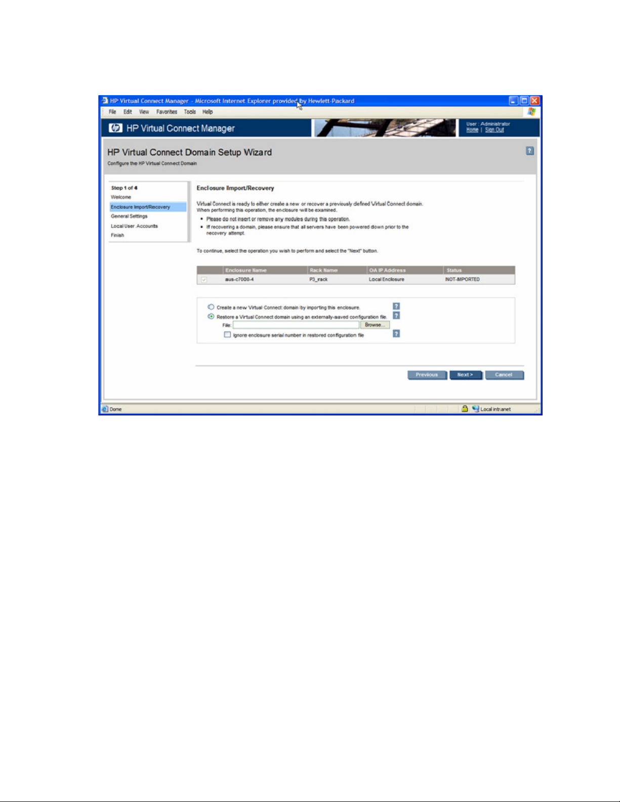
Next to continue restoring the enclosure. At the end of the restoration, the browser returns to the login
screen. After the domain is restored, one of the local user accounts from the original Virtual Connect
domain must be used to login.
General Settings
The Virtual Connect domain name must be unique within the data center, and can be up to 64 characters
without spaces or special characters.
HP Virtual Connect Manager 61
Page 62

The Domain Setup Wizard automatically assigns a domain name (enclosurename_vc_domain). This name
can be changed when running the setup wizard, or at anytime from the "Domain Settings (Domain
Configuration) screen (on page 150)."
HP Virtual Connect Manager 62
Page 63
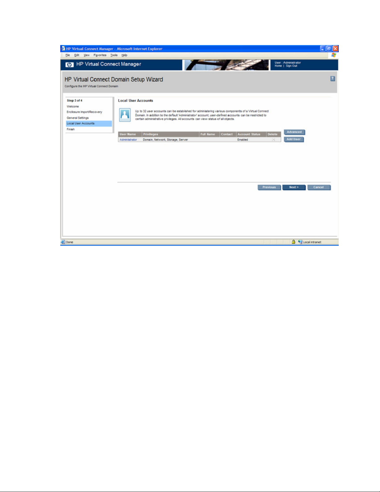
Local Users
The first time this page appears, the only local user account is the Administrator account, which has
domain privileges. The Administrator account cannot be deleted or have domain privileges removed. The
Administrator password can be changed. The default Administrator password is identified on the Default
Network Settings label on the VC-Enet module in bay 1 of the enclosure. To reset the Administrator
password to the factory default, see "Resetting the Administrator password and DNS settings (on page
14)."
The following tasks can be performed on this screen:
• To create a new local user account, click Add User. The User Settings screen is displayed.
• To edit attributes of a defined local account, select the user name from this screen.
• To delete a user account, click the Delete icon for that line item.
HP Virtual Connect Manager 63
Page 64

• To enable strong passwords or enable local users, click Advanced.
To enable the use of strong passwords, select the 'Require Strong Passwords' checkbox. Use the up and
down arrows to select a password length between 3 and 40 characters. With strong passwords enabled,
passwords must also contain at least one character from three of the following four categories:
• Upper-case character
• Lower-case character
• Numeric character
• Non-alphanumeric character
To enable local users, select the 'Enable Local Users' checkbox. To disable local users, deselect the
'Enable Local Users' checkbox. If you disable local users before properly setting up both directory services
groups and directory services, you cannot log in to the Virtual Connect Manager.
HP Virtual Connect Manager 64
Page 65

User Settings
Observe the following user settings guidelines:
• Username is a required field.
• Username must contain an alpha-numeric value with 1 to 13 characters.
• Password must contain an alpha-numeric value with 3 to 40 characters.
• If strong passwords are enabled, the password must contain the administrator-designated number of
characters, and at least one character from three of the following four categories:
o Upper-case character
o Lower-case character
o Numeric character
o Non-alphanumeric character
Up to 32 local user accounts can be created.
Each account can be set up to have a combination of up to four access privileges:
• Domain
o Define local user accounts, set passwords, define roles
o Import enclosures
o Name the VC domain
o Set the domain IP address
o Update firmware
HP Virtual Connect Manager 65
Page 66

o
Administer SSL certificates
o Delete the VC domain
o Save configuration to disk
o Restore the configuration from a backup
• Networking
o Configure network default settings
o Select the MAC address range to be used by the VC domain
o Create, delete, and edit networks
o Create, delete, and edit shared uplink sets
• Server
o Create, delete, and edit server Virtual Connect profiles
o Assign and unassign profiles to device bays
o Select and use available networks
o Power on and off server blades within the enclosure
• Storage
o Select the WWNs to be used by the domain
o Setup the connections to the external FC Fabrics
It is possible to create a user with no privileges. This user can only view status and settings.
NOTE: The vcmuser_ account is an internal Onboard Administrator account created and used
by Virtual Connect Manager to communicate with the Onboard Administrator. This account
can show up in the Onboard Administrator system log. This account cannot be changed or
deleted.
HP Virtual Connect Manager 66
Page 67

Finish domain wizard
Click Finish to complete this wizard, and then run the Network Setup Wizard ("HP Virtual Connect
Network Setup Wizard" on page 67) to define the Ethernet networks that will be available within the
Virtual Connect domain.
HP Virtual Connect Network Setup Wizard
This wizard establishes external Ethernet network connectivity for the HP BladeSystem c-Class enclosure
using HP Virtual Connect. A user account with network privileges is required to perform these operations.
Use this wizard to do the following:
• Identify the MAC addresses to be used on the servers deployed within this Virtual Connect domain.
• Choose the method of handling VLAN tagged packets from servers.
• Setup connections from the HP c-Class enclosure to the external Ethernet networks.
These connections can be uplinks dedicated to a specific Ethernet network or shared uplinks that
carry multiple Ethernet networks with the use of VLAN tags.
Be sure to connect any Ethernet module stacking cables before running the setup wizard.
HP Virtual Connect Manager 67
Page 68

To initiate this wizard, click the Network Setup Wizard link on the homepage, or select Network Setup
Wizard from the Tools pull-down menu.
MAC Address Settings
At this point in the wizard, you are asked to select the type of Ethernet MAC addresses to be used on the
server blades within the enclosure. Choose either the server factory default Ethernet MAC address that
came with the server or the Ethernet MAC addresses assigned by Virtual Connect. Be sure to fully
understand the following information before making this selection.
IMPORTANT: Configuring Virtual Connect to assign server blade MAC addresses requires
careful planning to ensure that the configured range of MAC addresses is used once within the
environment. Duplicate MAC addresses on an Ethernet network can result in a server network
Each server blade Ethernet NIC ships with a factory default MAC address. The MAC address is a 48-bit
number that uniquely identifies the Ethernet interface to other devices on the network. While the hardware
ships with default MAC addresses, Virtual Connect has the ability to assign MAC addresses that will
override the factory default MAC addresses while the server remains in that Virtual Connect enclosure.
When configured to assign MAC addresses, Virtual Connect securely manages the MAC addresses by
accessing the physical NICs through the enclosure Onboard Administrator and the iLO interfaces on the
individual server blades.
Always establish control processes to ensure that a unique MAC address range is used in each Virtual
Connect domain in the environment. Reusing address ranges could result in server network outages
caused by multiple servers having the same MAC addresses.
outage.
HP Virtual Connect Manager 68
Page 69

If using Virtual Connect assigned MAC addresses, the following notes apply:
• Virtual Connect automatically reserves both a primary address and an iSCSI MAC address for use
by multifunction gigabit server adapters, such as the HP NC373m PCI Express Dual Port
Multifunction Gigabit server adapter. Only the primary MAC address is used by standard (not
multifunction) Ethernet devices.
• If a server blade is moved from a Virtual Connect managed enclosure to a non-Virtual Connect
enclosure, the local MAC addresses on that server blade are automatically returned to the original
factory defaults.
If a server blade is removed from a bay within a Virtual Connect domain and installed in another bay in
the same Virtual Connect domain or in a bay in a different domain, it is assigned the new set of
addresses appropriate for that server location.
Assigned MAC addresses
The MAC address range used by the Virtual connect domain must be unique within the environment. HP
provides a set of pre-defined ranges that are for use by Virtual Connect Manager and will not conflict
with server factory default MAC addresses.
When using the HP-defined MAC address ranges, ensure that each range is used only once within the
environment.
HP Virtual Connect Manager 69
Page 70

Select the type and range of MAC address, and then click Next.
Selecting VC-assigned MAC address ranges
When using VC-assigned MAC addresses, you can choose between using an HP pre-defined MAC
address range or using a user-defined MAC address range.
• HP pre-defined MAC address range (recommended). These pre-defined ranges are reserved and will
never show up as factory default on any hardware. There are 64 ranges of 1024 unique addresses
to choose from. Be sure to use each range only once within a data center.
• User-defined MAC address range. To avoid potential conflict with other hardware MAC addresses
in the environment, consider using a subrange of MAC addresses reserved by the IEEE for locallyadministered MAC addresses. Ensure that the range does not conflict with any Ethernet device
already deployed within the enterprise.
IMPORTANT: If you plan to use RDP for RedHat Linux installation and also plan to use User- or
Select the type and range of MAC address, and then click Next.
HP-defined MAC addresses, you must import the enclosure before running RDP.
NOTE: After any server profiles are deployed using a selected MAC address range, that
range cannot be changed until all server profiles are deleted.
Stacking Links
Be sure to connect any Ethernet module stacking cables before running the setup wizard.
HP Virtual Connect Manager 70
Page 71

IMPORTANT: For a Virtual Connect environment to operate properly, all Virtual Connect
Ethernet modules within the Virtual Connect domain must be interconnected with stacking links.
HP strongly recommends that redundancy be maintained in stacking links to ensure continued
connectivity of servers to the external networks.
At this point in the wizard, the user can see if all stacking cables are properly installed so that all Virtual
Connect Ethernet modules within the domain are interconnected:
• Connection Status indicates whether all of the Virtual Connect Ethernet modules within the domain
are interconnected with stacking cables and accessible. Lack of connection status to all Virtual
Connect Ethernet modules results in a critical alert.
o OK indicates that all modules are connected.
o Failed indicates that one or more modules are not connected properly. Check the cable
connections.
• Redundancy Status indicates if all Virtual Connect Ethernet modules would remain fully
interconnected if a module or external cable was removed or failed. Horizontally-adjacent modules
are considered to have OK redundancy status because of the reliability of their internal link.
o OK indicates redundant/reliable connections are in place.
o Degraded indicates additional stacking cables should be connected to provide full redundancy.
The table on this screen lists all of the Ethernet stacking links found within the Virtual Connect domain.
Each row of the table identifies the link speed and the connections on both sides of the link, identified by
the module and port number.
Port X0 indicates the 10Gb port connected through the midplane of horizontally-adjacent Virtual Connect
Ethernet modules.
For additional information, see “Supported configurations (on page 22)” and “Recommended stacking
connections (on page 34)."
NOTE: Virtual Connect does not support stacking for FC modules, so each VC-FC module
requires uplink connections to the external FC SAN environment.
HP Virtual Connect Manager 71
Page 72

Define Network Connection
To begin, select one of the following external network connections:
• Connection with uplink(s) dedicated to a single network ("Define Single Network" on page 74)
This selection leads to the definition of a network within the Virtual Connect environment and
identifies any module uplink ports used to connect to that network in the data center. Internal-only
networks (without external uplinks) can also be defined.
These single networks will pass through any VLAN tags added by the server or added externally.
• Connection with uplink(s) carrying multiple networks (using VLAN tagging) ("Define Shared Uplink
Port Set" on page 75)
This choice leads to the definition of multiple networks within the Virtual Connect environment that all
share a common set of module uplink ports. Network traffic from each of the networks within the
Virtual Connect environment receives a VLAN tag as it exits on a shared uplink port. Virtual Connect
uses the VLAN tag on incoming network traffic to place it on the appropriate internal network.
Ethernet VLAN tags are added on egress and stripped on ingress.
This type of network connection should not be used when VLAN tags are being inserted by the
server.
NOTE: One network can be designated as a native VLAN, causing all untagged incoming
Ethernet packets to be placed on this network. For additional information, see "Shared uplink
sets and VLAN tagging (on page 110)."
HP Virtual Connect Manager 72
Page 73

After each network is defined, the user has the option of defining additional networks or finishing the
wizard.
To determine the types of network connections to use, see "Connecting Virtual Connect Ethernet module
uplinks (on page 36)."
HP Virtual Connect Manager 73
Page 74
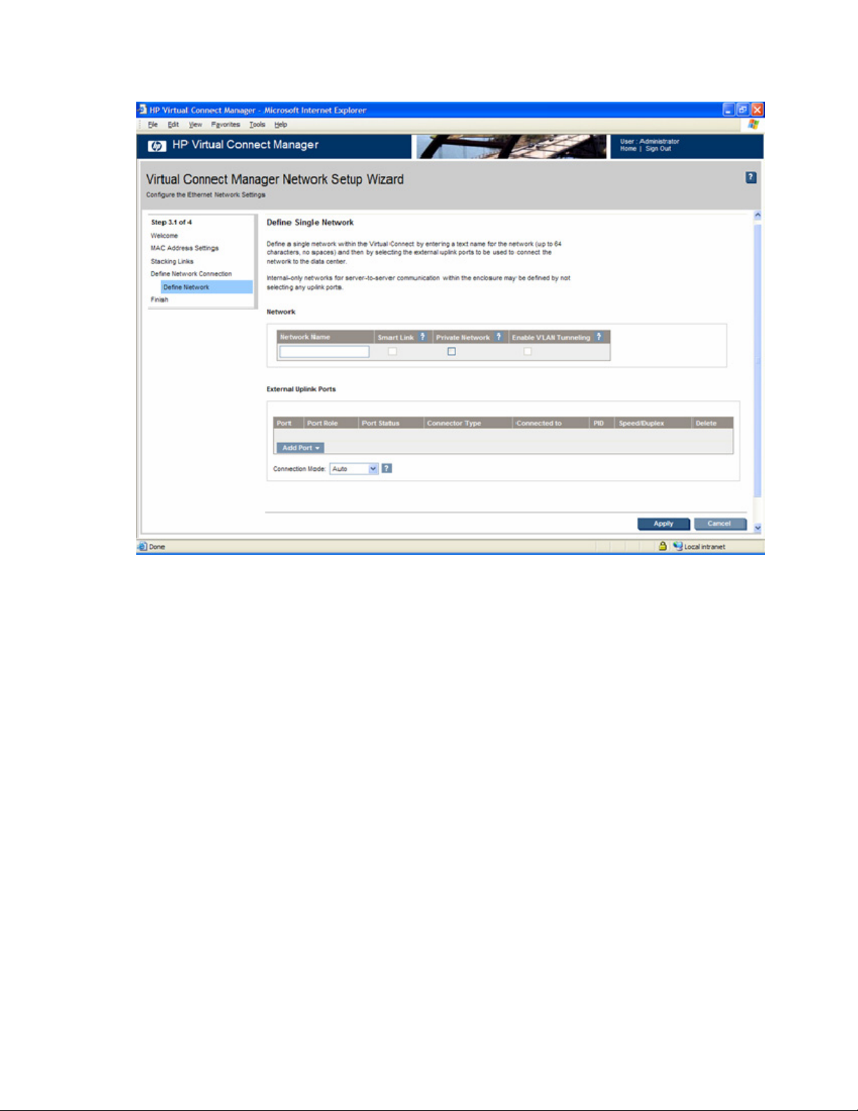
Define Single Network
To define a network:
1. Enter a name for the network that will be easily understood and recognized by the server
administrators defining and deploying server profiles. The network name can be up to 64 characters
in length (no spaces).
2. To enable Smart Link, select the box under Smart Link (on page 93).
3. To designate as a private network, select the box under Private Network ("Private Networks" on
page 93).
4. To enable VLAN tunneling, select the box under Enable VLAN Tunneling. This option is only
available if the 'Tunnel VLAN Tags' radio button is selected on the Advanced Settings tab of the
Ethernet Settings screen. See server VLAN tagging support restrictions and limitations. ("Restrictions
and limitations" on page 108)
5. Select the specific Virtual Connect Ethernet module external uplink ports that will connect the network
to the data center. The available external ports are listed in the multi-level Add Port drop-down menu.
Each port is labeled as linked or not linked. This status refers to whether or not a current connection
to an external switch exists.
If the network is to be local to the servers within the VC domain (enclosure), then no uplinks need to be
selected.
For additional information, see "Define Ethernet Network screen (on page 94)."
HP Virtual Connect Manager 74
Page 75

Define Shared Uplink Port Set
To define multiple networks that share a common set of external uplink ports:
1. Enter an overall name for the set of shared uplinks (up to 64 characters, no spaces).
2. From the Add Port drop-down menu, select the external uplink ports that will carry these networks.
3. Click Add Network to define the name and VLAN identifier of each network to use these shared
uplinks.
For additional information, see "Shared uplink sets and VLAN tagging (on page 110)."
a. To use native VLAN, select the box under Native. Only one VLAN can be designated as the
native VLAN.
b. To use Smart Link, select the box under Smart Link (on page 93).
c. To designate as a private network, select the box under Private Network ("Private Networks" on
page 93).
4. Click Apply.
For additional information, see "Define New Shared Uplink Set screen (on page 110)."
Finish network wizard
When the Network Setup Wizard completes, external Fibre Channel connectivity can be configured (if
applicable) or server profiles can be defined and associated with server blades.
To establish external Fibre Channel connectivity:
1. Be sure the Start the Fibre Channel Wizard checkbox is selected.
HP Virtual Connect Manager 75
Page 76
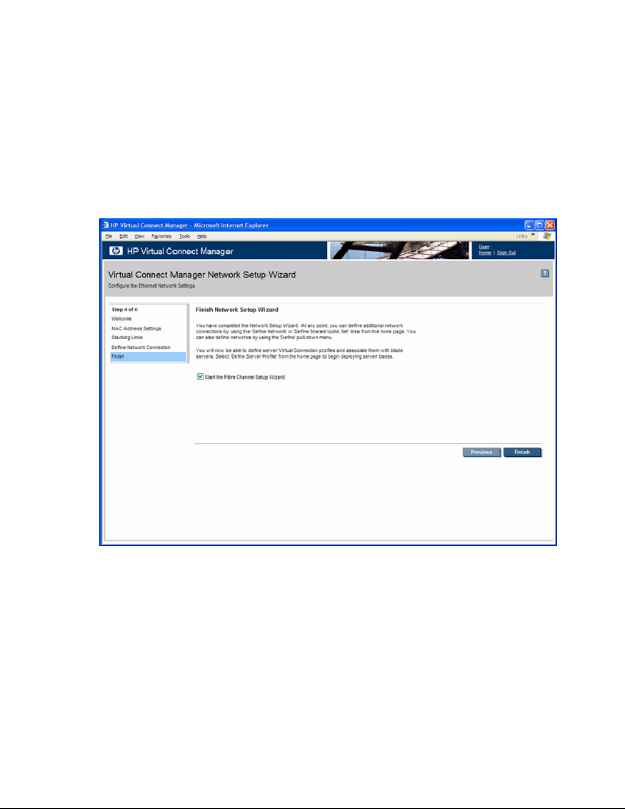
2.
Click Finish. The Fibre Channel Wizard Welcome screen is displayed.
To begin deploying server blades:
1. Be sure the Start Fibre Channel Wizard checkbox is not selected.
2. Click Finish.
3. Select Define Server Profile from the homepage.
Additional network connections can be defined at any time by using one of the following methods:
• Select the Define a Network link on the homepage.
• Select the Define a Shared Uplink Set link on the homepage.
• Select Ethernet Network from the Define pull-down menu.
HP Virtual Connect Fibre Channel Setup Wizard
This wizard configures external Fibre Channel connectivity for the HP BladeSystem c-Class enclosure using
HP Virtual Connect. A user account with storage privileges is required to perform these operations. Use
this wizard to do the following:
• Identify WWNs to be used on the server blades deployed within this Virtual Connect domain.
• Create SAN fabrics.
HP Virtual Connect Manager 76
Page 77
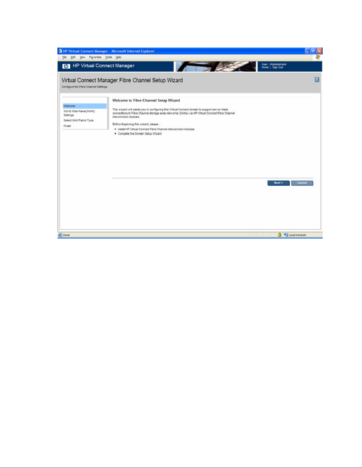
To initiate this wizard, click the Fibre Channel Wizard link on the homepage, or select Fibre Channel
Setup Wizard from the Tools pull-down menu.
WWN settings
At this point in the wizard, you are asked to select the type of FC WWNs to be used on the server blades
within the enclosure. You can choose to use the server factory default WWNs that came with the FC HBA
mezzanine card or to use FC WWNs assigned by Virtual Connect. Be sure to fully understand the
following information before making this selection.
Each server blade FC HBA mezzanine card ships with factory default port and node WWNs for each FC
HBA port. Each WWN is a 64-bit number that uniquely identifies the FC HBA port/node to other devices
on the network. While the hardware ships with default WWNs, Virtual Connect has the ability to assign
WWNs that will override the factory default WWNs while the server remains in that Virtual Connect
enclosure. When configured to assign WWNs, Virtual Connect securely manages the WWNs by
accessing the physical FC HBA through the enclosure Onboard Administrator and the iLO interfaces on
the individual server blades.
When assigning WWNs to a FC HBA port, Virtual Connect will assign both a port WWN and a node
WWN. Because the port WWN is typically used for configuring fabric zoning, it is the WWN displayed
throughout the Virtual Connect user interface. The assigned node WWN is always the same as the port
WWN incremented by one.
Configuring Virtual Connect to assign WWNs in server blades maintains a consistent storage identity
(WWN) even when the underlying server hardware is changed. This method allows server blades to be
replaced without affecting the external Fibre Channel SAN administration.
HP Virtual Connect Manager 77
Page 78
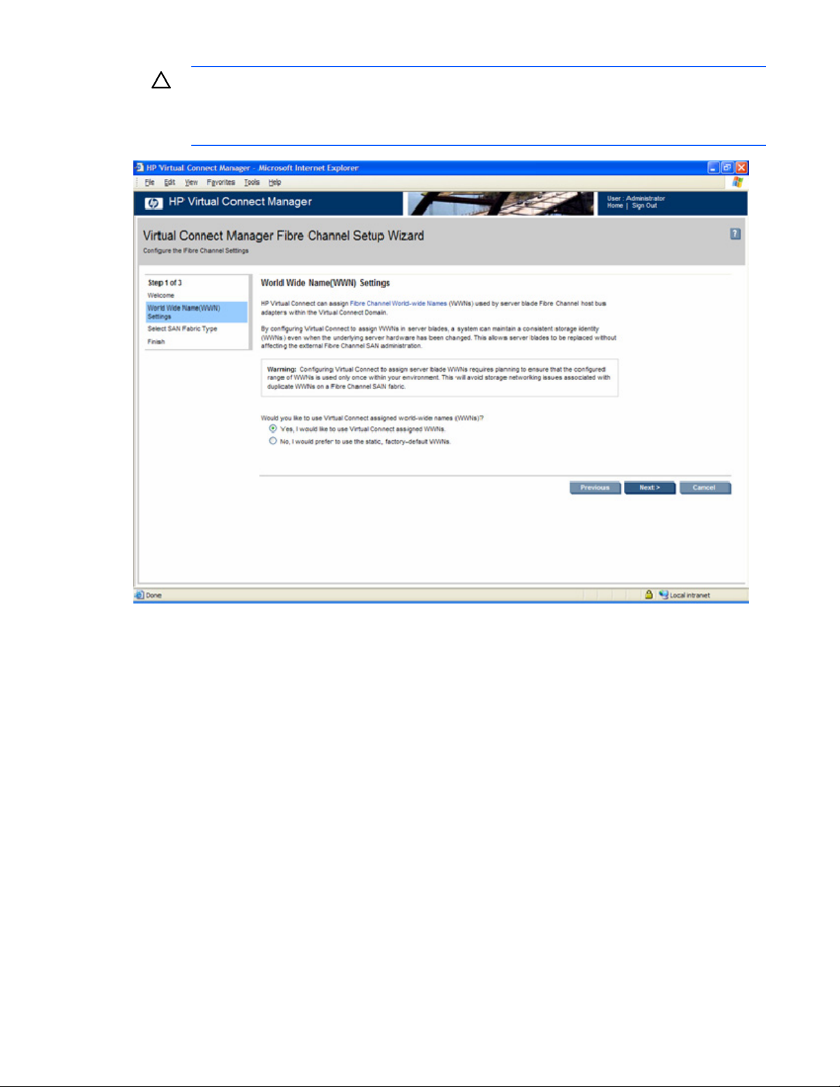
CAUTION: To avoid storage networking issues and potential loss of data associated with
duplicate WWNs on a FC SAN fabric, plan carefully when allowing Virtual Connect to assign
server blade WWNs so that the configured range of WWNs is used only once within the
environment.
Assigned WWNs
The WWN range used by the Virtual Connect domain must be unique within the environment. HP
provides a set of pre-defined ranges that are reserved for use by Virtual Connect and do not conflict with
server factory default WWNs.
When using the HP-defined WWN ranges, be sure that each range is used only once within the
environment.
HP Virtual Connect Manager 78
Page 79

Select the type and range of WWNs, and then click Next.
Select SAN Fabric Type
Select the type of SAN fabric to create:
• Static—permanently maps the server connection to a specific uplink port.
• Dynamic—load balances traffic based on the number of SAN logins on a port. This type of mapping
provides failover and failback within the Virtual Connect fabric.
HP Virtual Connect Manager 79
Page 80

For additional information on creating FC SAN fabrics, see "Storage overview (on page 118)."
Define SAN Fabric
The following actions are available on this screen:
• Name the fabric.
• Select the uplink port speed.
• Select the uplink port(s) to be used. Only uplinks on the same bay can be in the same SAN fabric.
HP Virtual Connect Manager 80
Page 81

• When finished, click Apply.
Finish Fibre Channel wizard
When the Fibre Channel Setup Wizard completes, server profiles can be defined and associated with
server blades.
To begin deploying server blades:
1. Be sure the Start the Server Profile Wizard checkbox is selected.
2. Click Finish. The Server Profile Wizard Welcome screen appears.
The FC SAN configuration can be changed at any time by using one of the following methods:
• Select the Fibre Channel Settings (WWN) link on the homepage.
HP Virtual Connect Manager 81
Page 82

• Select Fibre Channel Settings from the Configure pull-down menu.
Virtual Connect Manager Server Profile Wizard
This wizard allows you to setup and configure network/SAN connections for the server blades within the
enclosure.
With the wizard, you can define a server profile template that identifies the server connectivity to use on
server blades within the enclosure. The template can then be used to automatically create and apply
server profiles to up to 16 server blades. Once created, the individual server profiles can be edited
independently.
Before beginning the server profile wizard, do the following:
• Complete the Network Setup Wizard.
• Complete the Fibre Channel Setup Wizard (if applicable).
• Ensure that any server blades to be configured using this wizard are powered off.
This wizard walks you through the following tasks:
• Designate virtual serial number settings (optional)
• Define a server profile template
• Assign server profiles
• Name server profiles
HP Virtual Connect Manager 82
Page 83

• Create server profiles
Virtual Serial Number Settings
Use this screen to assign virtual serial numbers to server blades within the domain.
By configuring Virtual Connect to assign Virtual Serial Numbers, a server blade can present a single
serial number to licensing software. This method avoids the need to re-install serial number sensitive
software after a recovery. Configuring Virtual Connect to assign virtual serial numbers requires planning
to ensure that the configured range of serial numbers are used only once within your environment.
CAUTION: The use of virtual server ID settings might prevent the proper operation of software
designed to track servers by serial number or UUID. Do not enable this feature until you have
considered and understand the impact to the entire software environment that the servers
operate in. This impact includes, but is not limited to, warranty service, asset tracking, server
deployment, and software licensing.
HP Virtual Connect Manager 83
Page 84

For additional information, see "Virtual Server ID Settings (on page 148)."
HP Virtual Connect Manager 84
Page 85
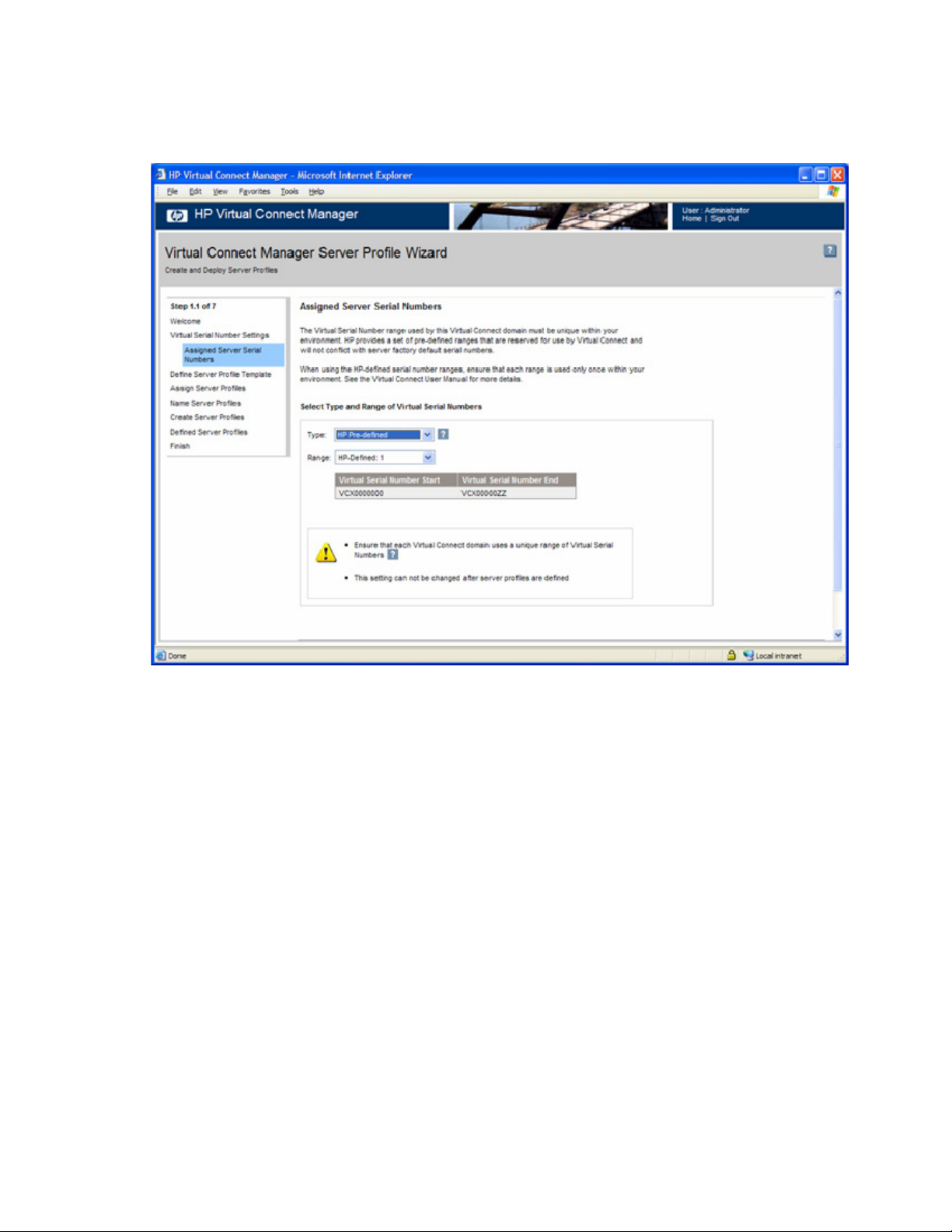
Assigned Server Serial Numbers
Select the type and range of virtual serial numbers. Be sure that each range is used only once in your
environment.
Define Server Profile Template
Use this screen to create a new server profile definition, which defines and configures Ethernet and Fibre
Channel connectivity for the server.
HP Virtual Connect Manager 85
Page 86

For additional information, see "Define a Server Profile screen ("Define Server Profile screen" on page
131)" and "Advanced Profile Settings (on page 133)."
HP Virtual Connect Manager 86
Page 87

Assign Server Profiles
Server profiles are created from the defined template. When these server profiles are created, you can
choose to automatically assign them to device bays or to leave the server profiles unassigned.
HP Virtual Connect Manager 87
Page 88

Name Server Profiles
The table displays the automatically-generated names that will be assigned to the new server profiles. You
can edit the profile names before continuing. Be sure the names are unique and meaningful.
Create Server Profiles
This screen provides confirmation of each profile that was created.
HP Virtual Connect Manager 88
Page 89

If creation of a server profile failed, see "Server profile troubleshooting (on page 147)."
HP Virtual Connect Manager 89
Page 90
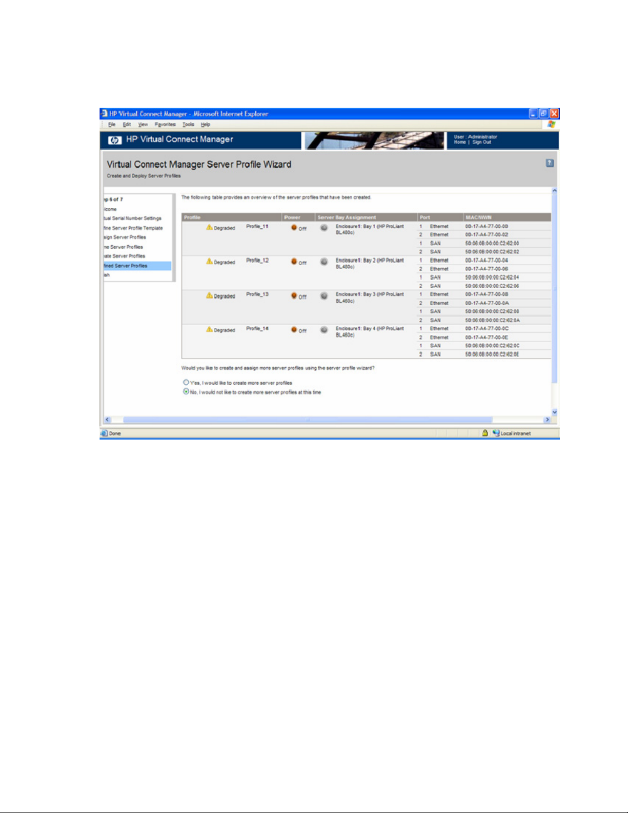
Defined Server Profiles
This screen provides an overview of the server profiles that have been created. For additional information,
see "Server Profiles screen (on page 142)."
HP Virtual Connect Manager 90
Page 91

Finish Server Profile Wizard
The Server Profile Wizard is complete. Click Finish to display the Virtual Connect Manager homepage.
Verifying data center connections
After completing the cabling between the HP BladeSystem c-Class enclosure and the data center
networks, use the following techniques to verify that the network connections are operating properly:
• Verify that all external connections are linked and operating at the right speed.
• Review the Virtual Connect Manager Network status screens ("Verify network status using VC
Manager" on page 92).
• Use port IDs to verify network connections.
Verify link and speed
• Configure a server and verify network connectivity.
Verify that all external ports connected to the data center are linked and are operating at the appropriate
speed.
1. Verify that all Virtual Connect Ethernet modules are properly powered on and functioning. The
module status LED for all modules connected and configured in Virtual Connect for data center use
should be green.
HP Virtual Connect Manager 91
Page 92

If the LED is not green, use the HP Onboard Administrator user interface to diagnose the problem
and verify that the module is properly powered.
2. Verify that all HP 4Gb VC-FC Modules are properly powered on and functioning. The module status
LED for all modules connected and configured in Virtual Connect for data center use should be
green.
If the LED is not green, use the HP Onboard Administrator user interface to diagnose the problem
and verify that the module is properly powered.
3. Verify that the data center switches are powered on.
4. Verify that each external port is linked and operating at the appropriate speed using link/speed
activity LEDs for that port.
If ports are not linked, verify the cables being used are not defective, and verify that both ends of the
link are configured for the same speed/duplex settings. Both sides of the configuration must match
for the link to be established. For autonegotiation, both ports must be configured to run
autonegotiation. To use a forced speed, (for example 100 Mb full-duplex), both ports must be
configured to be the same forced speed. Mismatched configuration can result in ports not linking up,
or not functioning properly. Note that Virtual Connect Ethernet modules do not support half-duplex
operations.
5. Verify that the port status indicator (port number) of each configured external port is illuminated
green (assuming no port IDs are turned on). This status indicates that the port is actively configured
as part of an external connection.
Verify network status using VC Manager
The HP Virtual Connect Manager provides many status and summary screens that can be used to verify
that the networks were defined properly and mapped to the appropriate network. These summary screens
can be used to print a report for review and reference.
The most useful summary screen is the Ethernet Networks (External Connections) screen (on page 96). To
access this screen, click the Ethernet Networks link in the left VC Manager navigation window.
The following actions are available from this screen:
• Identify the external ports associated with each Ethernet network.
• View the current port status (link, speed) of each external port.
• View the current active/standby state of each external port.
• Access information about attached switches (if the external switch supports LLDP).
• Highlight the port IDs for all external ports associated with a specific network.
HP Virtual Connect Manager 92
Page 93

Network management
Networks overview
The Virtual Connect Ethernet module uses standard Ethernet bridge circuitry with special firmware so that
it functions as a configurable Ethernet port aggregator. For a specific external data center connection,
only the selected server Ethernet NIC ports are visible on what appears to be an isolated, private, loopfree network. The Virtual Connect Ethernet module uplinks do not participate in the data center Spanning
Tree Protocol or other switch management protocols that could disrupt the data center network.
The Virtual Connect Ethernet module uplinks support link aggregation, link layer discovery protocol (LLDP),
and VLAN tagging. VLAN tagging enables uplinks to be shared to carry multiple networks. Versions 1.15
and higher of Virtual Connect allows users to identify an associated network as the native VLAN, causing
all untagged incoming Ethernet packets to be placed onto the designated network. Only one associated
network can be designated as the native VLAN. All outgoing Ethernet packets are VLAN tagged.
Each network defined within Virtual Connect may have one or more uplinks. Virtual Connect
independently ensures that no loops are created within the enclosure and that the resulting tree structure is
optimized for the uplinks to the data center.
When multiple uplinks are used on a network, HP Virtual Connect Manager first verifies if any of the ports
can be collected together into an aggregation group (requires connections to go from a single Virtual
Connect Ethernet module to a single data center switch), and then it picks a single link (or aggregation
group) as the connection to the external network. The remaining connections are blocked and held as
standby ports.
Smart Link
Enabling Smart Link configures the network so that if all external links lose their link to external switches,
Virtual Connect drops the Ethernet link on all local server blade Ethernet ports connected to that network.
This feature can be useful when using certain server network teaming (bonding) configurations.
Private Networks
The Private Networks option provides extra networking security. When checked, the network is configured
so that all server ports connected to it cannot communicate with each other within the Virtual Connect
domain. All packets from servers are sent through the VC domain and out the uplink ports only. Servers
on the network can only communicate with each other through an external Layer 3 router that redirects the
traffic back to the VC domain.
Network management 93
Page 94
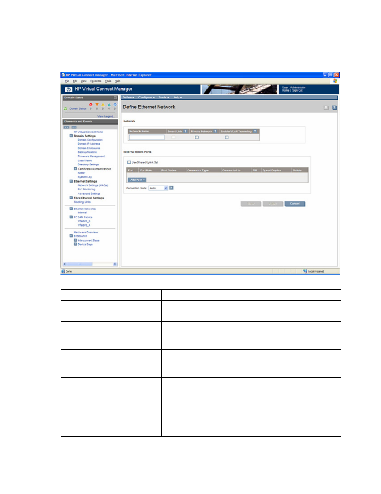
Define Ethernet Network screen
The Define Ethernet Network screen is accessible to all users with network privileges from the Define a
Network link on the Virtual Connect Manager homepage or the Define pull-down menu.
The following table describes the fields within the Define Ethernet Network screen.
Field name Description
Network
Network Name Name of the network
Smart Link (on page 93) Select whether to enable (checked) or disable (unchecked) Smart Link
Private Network ("Private Networks" on
page 93)
Enable VLAN Tunneling ("Server VLAN
Tagging Support" on page 106)
External Uplink Ports
Use Shared Uplink Set Enables selection or creation of a shared uplink set
Port Network port locations (enclosure, bay, and port numbers)
Port Role Applicable when Failover Connection Mode is selected. The port can
Port Status Displays the active link status and interface speed of the selected port
Connector Type Displays the type of connector on the port, for example RJ-45
Select whether to designate (checked) or not designate (unchecked) this
network as a private network
Select whether to enable (checked) or disable (unchecked) VLAN
Tunneling (this option is not available if VLAN mapping is enabled)
be designated as Primary or Secondary.
Network management 94
Page 95

Field name Description
Connected to If the port is connected to a switch that supports LLDP, the switch MAC
address and switch port are displayed. A link is provided to obtain
more information about the far-end switch port.
PID When selected, sets/clears the port identifier color as blue on the HP
1/10Gb VC-Enet module to aid in the location of the specific uplink.
The PID status for the overall network is also displayed.
Speed/Duplex Pull-down menu to specify the speed and duplex (where applicable) of
the uplink port. Half-duplex operations are not supported by the VC-Enet
module.
Delete Click to delete the line item.
The following table describes the available actions in the Define Ethernet Network Screen. Clicking
another link in the pull-down menu or left-hand navigation window causes current edits that have not been
applied to be lost.
Task Action
Enable Smart Link on the network being
defined
Designate the network as a private
network
Enable VLAN tunneling Select the box under Enable VLAN Tunneling. This option is only
Add an external uplink port to the
network
Change the uplink interface port speed
or disable the port
Change connection mode Click the down arrow in the box next to Connection Mode, and then
Delete an added port Click X in the Delete column for that port.
Clear unsaved changes on the screen Click Clear.
Save changes and remain on this
screen
Cancel without saving changes and
return to the summary screen
Select the box under Smart Link.
Select the box under Private Network.
available if the 'Tunnel VLAN Tags' radio button is selected on the
Advanced Settings tab of the Ethernet Settings screen.
Click the Add Port drop-down box and select an available port.
Click the drop-down box under Speed/Duplex, and then select a
setting.
select Auto or Failover. For a description of these modes, see "Defining
a network (on page 95)."
Click Apply.
Click Cancel.
Defining a network
To define a standalone network:
1. Enter a network name. The network name can be up to 64 characters in length (no spaces).
2. Select whether to enable (checked) or disable (unchecked) Smart Link (on page 93).
3. Select whether to designate (checked) or not designate (unchecked) this network as a private
network ("Private Networks" on page 93).
Network management 95
Page 96

4.
Select whether to enable (checked) or disable (unchecked) VLAN tunneling ("Server VLAN Tagging
Support" on page 106). This option is only available if the 'Tunnel VLAN Tags' radio button is
selected on the Advanced Settings tab of the Ethernet Settings screen.
5. If the network is to be used only internal to the Virtual Connect domain or enclosure, go to step 7 (do
not add any external ports).
6. Add one or more external port using the Add Port pull-down menu. Only available ports are listed
and they will display the current port link status. Select two or more ports to ensure a high
availability connection.
7. Select the Connection Mode:
o Auto (recommended)—This mode enables the uplinks to attempt to form aggregation groups
(using IEEE 802.3ad link aggregation control protocol) and to select the highest-performance
uplink as the active path to external networks.
Aggregation groups require multiple ports from a single Virtual Connect Ethernet module to be
connected to a single external switch that supports automatic formation of LACP aggregation
groups. Multiple aggregation groups may be formed from the ports selected for the network. The
highest performing aggregation group is selected as active with other aggregation groups and
individual links used as standby connections.
o Failover—If this mode is selected, set the port to Primary or Secondary. Only a single link is used
as the active link to the external networks with other ports used as standby connections.
8. Click Apply or OK. The network is now defined and available for use in creating server profiles.
To define a network that uses an existing Shared Uplink Set, use the Define/Edit Shared Uplink Set screen
or define the additional network as follows:
1. Enter the network name.
2. Select the Use Shared Uplink Set box.
3. Select an existing Network from the dropdown list or click the Create icon.
If the Create icon is selected, the Define a Shared Uplink Set screen appears so that a new Shared
Uplink Set can be created.
4. Enter an external VLAN ID.
5. Click Apply.
To create an internal network, which connects one server to another, do not select a port. Enter the
network name and then click Define Network.
NOTE: By default, Virtual Connect supports Jumbo Frames up to 9KB.
Ethernet Networks (External Connections) screen
To view a list of all defined Ethernet networks, click Ethernet Networks in the left window.
Network management 96
Page 97

This summary screen displays the external connections for each network and is available to all authorized
users.
The following table describes the columns within the summary table on the Ethernet Networks (External
Connections) screen.
Column name Description
Ethernet Networks Shows the overall network status, network name, and PID state
Shared Uplink Set (VLAN ID) Shows the name of the shared uplink set and its VLAN ID (if applicable)
Port Status Shows whether each individual port associated with the network is
linked or unlinked and the current link speed
Connector Type Displays the type of connector on the port, for example, RJ-45
Connected to If the individual port is connected to a switch that supports LLDP, the
switch MAC address and switch port are displayed. A link is provided
to obtain more information about the far-end switch port.
Uplink Port Lists the status of the individual port and the location of the individual
port (enclosure, bay, port)
The following table describes the available actions in the Ethernet Networks (External Connections)
screen. Clicking another link in the pull-down menu or left navigation window causes current edits that
have not been applied to be lost.
Task Action
Sort list view Click the down arrow next to the Show box to display All Networks, or
one specific network.
Edit a network Click on the name of the network in the table listing.
Edit a shared uplink set Click on the name of the shared uplink set in the table listing.
Network management 97
Page 98
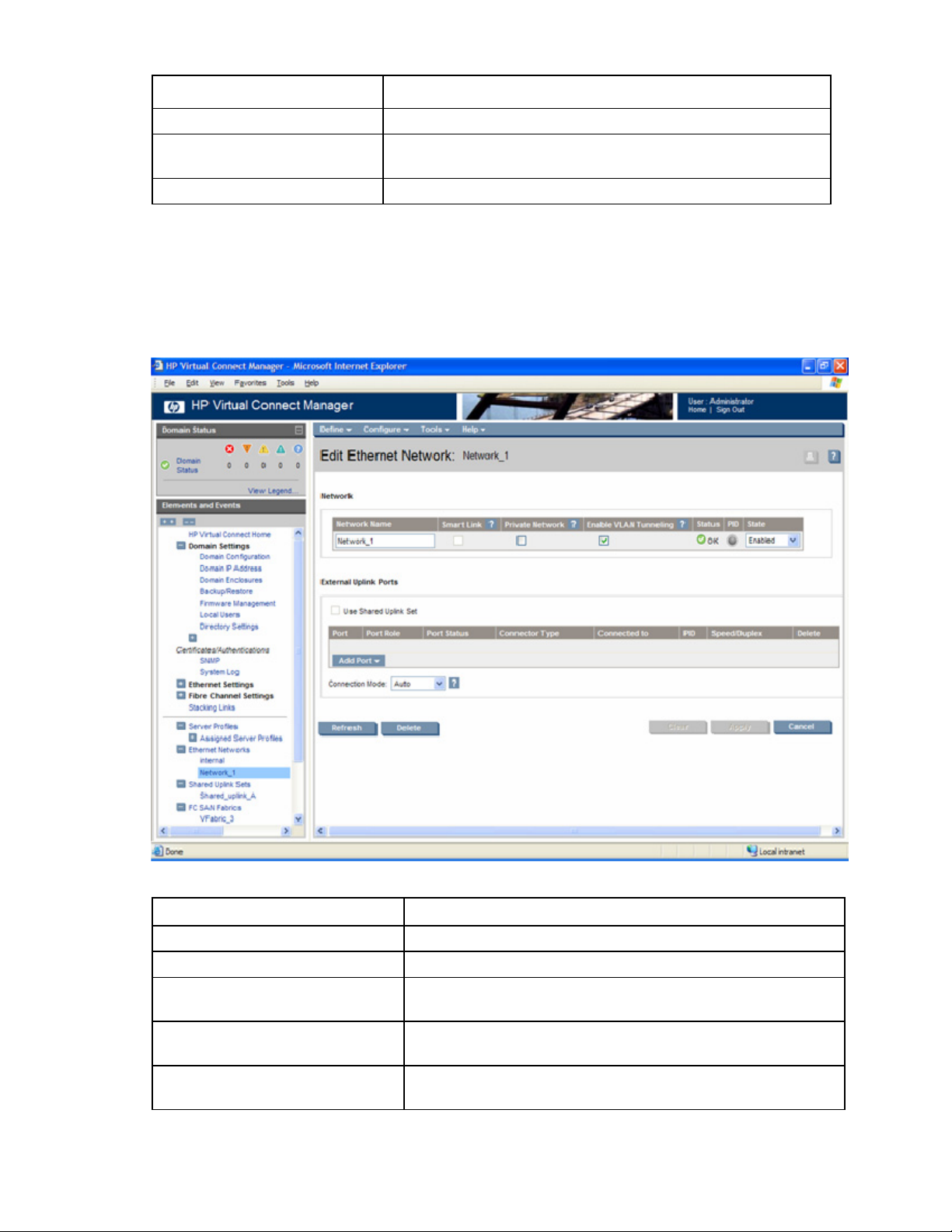
Task Action
Define a new network Click Define Network.
Illuminate the PID for all uplink ports
Click on the circle next to the network in the list.
associated with a network
View a printable report Click View Printable Report.
Edit Ethernet Network screen
Use this screen to edit the properties of an existing network or to delete a network.
This screen has similar fields to the Define Ethernet Network screen (on page 94). This screen can only be
edited by users with network privileges, but it is viewable by all authorized users.
The following table describes the fields within the Edit Network screen.
Field name Description
Network
Network Name Name of the network
Smart Link ? Shows whether Smart Link is enabled (checked) or disabled
(unchecked)
Private Network ? Shows whether this network is designated (checked) or not designated
(unchecked) as a private network
Enable VLAN Tunneling ? Shows whether VLAN tunneling is enabled (checked) or disabled
(unchecked)
Network management 98
Page 99

Field name Description
Status Displays the current status of the network
PID PID status for the overall network
State Displays the current state of the network (enabled or disabled)
External Uplink Ports
Use Shared Uplink Set Enables selection or creation of a shared uplink set
Port Network port locations (enclosure, bay, and port numbers)
Port Role Applicable when Failover Connection Mode is selected. The port can
be designated as Primary or Secondary.
Port Status Displays the current linked status of the selected port
Connector Type Displays the type of connector on the port, for example, RJ-45
Connected to If the port is connected to a switch that supports LLDP, the switch MAC
address and switch port number are displayed. A link is provided to
obtain more information about the far-end switch port.
PID When selected, this option sets/clears the port identifier color as blue
on the HP 1/10Gb VC-Enet Module to aid in the location of the
specific uplink. The PID status for the overall network is also displayed.
Speed/Duplex Pull-down menu to specify the speed and duplex (where applicable) of
the uplink port
Delete Click to delete the line item.
The following table describes the available actions in the Edit Network Screen. Clicking another link in the
pull-down menu or left-hand navigation window causes current edits that have not been applied to be lost.
Task Action
Enable or disable Smart Link on the
network being defined
Designate or do not designate the
network as a private network
Enable or disable VLAN tunneling Select the box under Enabled VLAN Tunneling. This option is only
Enable or disable the network Click the drop-down box under State, and then select a setting.
Add an external uplink port to the
network
Change the uplink interface port speed
or disable the port
Change connection mode Click the down arrow in the box next to Connection Mode, and then
Delete an added port Click X in the Delete column for that port.
View updated information on the
network
Delete the network Click Delete.
Clear unsaved changes on the screen Click Clear.
Select the box under Smart Link.
Select the box under Private Network.
available if the 'Tunnel VLAN Tags' radio button is selected on the
Advanced Settings tab of the Ethernet Settings screen.
Click the Add Port drop-down box and select an available port.
Click the drop-down box under Speed/Duplex, and then select a
setting.
select Auto or Failover. For a description of these modes, see "Defining
a network (on page 95)."
Click Refresh.
Network management 99
Page 100

Task Action
Save changes and remain on this
screen
Cancel without saving changes and
return to the summary screen
Click Apply.
Click Cancel.
Ethernet Networks (Server Connections) screen
This summary screen lists the server ports connected to each network in the Virtual Connect domain. This
screen is viewable by all authorized users.
The following table describes the columns within the Ethernet Networks (Server Connections) screen.
Column name Description
Ethernet Networks Shows the overall network status, network name, and PID state
Port Shows the overall status of the individual server port as well as the port
number within the server
MAC Lists the MAC address for the server port
Location Lists the enclosure and device bay for the server blade (when the profile
is assigned to a device bay)
Profile Shows the overall status of the associated server profile and the server
profile name. Click the profile name to display the edit screen for the
profile.
Network management 100
 Loading...