

Page 1

HP Virtual Connect Enterprise Manager 6.1
User Guide
HP Part Number: 460927-007
Published: June 2010, Seventh Edition
Page 2

© Copyright 2007, 2010 Hewlett-Packard Development Company, L.P.
Legal Notices
Confidential computer software. Valid license from HP required for possession, use or copying. Consistent with FAR 12.211 and 12.212, Commercial
Computer Software, Computer Software Documentation, and Technical Data for Commercial Items are licensed to the U.S. Government under
vendor's standard commercial license.
The information contained herein is subject to change without notice. The only warranties for HP products and services are set forth in the express
warranty statements accompanying such products and services. Nothing herein should be construed as constituting an additional warranty. HP shall
not be liable for technical or editorial errors or omissions contained herein.
Acknowledgments
Microsoft® and Windows® are U.S. registered trademarks of Microsoft Corporation.
Page 3

Table of Contents
About this document......................................................................................9
Intended audience..................................................................................................................................9
Publishing history....................................................................................................................................9
Related documents..................................................................................................................................9
HP encourages your comments.................................................................................................................9
1 Introduction.............................................................................................11
Key features and benefits.......................................................................................................................11
Key features....................................................................................................................................11
Key benefits....................................................................................................................................11
What's new.........................................................................................................................................12
Platform support....................................................................................................................................12
Product licensing...................................................................................................................................12
Architectural overview............................................................................................................................13
HP Virtual Connect technology..........................................................................................................13
Managing HP Virtual Connect...........................................................................................................15
HP Virtual Connect Manager.......................................................................................................15
HP Virtual Connect Enterprise Manager.........................................................................................15
VCEM operations............................................................................................................................15
Setup and configuration summary...........................................................................................................17
2 Installing and configuring VCEM................................................................19
Preparing for a VCEM installation...........................................................................................................19
Installation prerequisites.........................................................................................................................19
Hardware requirements....................................................................................................................19
Software requirements......................................................................................................................19
Virtual Connect requirements.............................................................................................................20
Managed servers.............................................................................................................................20
Installing VCEM....................................................................................................................................21
Removing VCEM...................................................................................................................................21
Performing post-installation configuration tasks..........................................................................................22
Post-installation configuration tasks.....................................................................................................22
Upgrading incompatible firmware modes and versions....................................................................23
VCEM home page................................................................................................................................24
3 Managing VC Domains............................................................................25
VC Domains.........................................................................................................................................25
Requirements for adding a VC Domain to a VC Domain Group.............................................................27
Mixed Virtual Connect firmware versions and firmware compatibility in a VC Domain Group................29
Virtual Connect 3.0x features that must be disabled in a VC Domain to be part of the VC Domain Group
with Virtual Connect firmware 2.1x and 2.3x..................................................................................30
Virtual Connect 2.3x features that must be disabled in a VC Domain to be part of the VC Domain Group
with Virtual Connect firmware 2.1x................................................................................................31
VC Domain tasks.............................................................................................................................34
Licensing an enclosure for VCEM.......................................................................................................34
Creating a VC Domain Group...........................................................................................................35
Adding a VC Domain to a VC Domain Group.....................................................................................37
Removing a VC Domain from a VC Domain Group..............................................................................38
Working with multienclosure VC Domains...........................................................................................39
VC Domain Maintenance..................................................................................................................41
VC Domain Group configuration replicated to other VC Domains during VC Domain Maintenance.......43
Performing VC Domain Maintenance.............................................................................................44
Table of Contents 3
Page 4

Backing up and restoring domain configurations through VC Domain Maintenance.............................45
Changes in Virtual Connect Manager that might affect completing VC Domain Maintenance...............46
Working with HP Virtual Connect 8Gb Fibre Channel Module for c-Class BladeSystem........................46
Adding or removing remote enclosures from a multienclosure domain in VC Domain Maintenance........46
Canceling a VC Domain Maintenance task.........................................................................................46
Resynchronizing a VC Domain with Configuration Mismatch..................................................................47
4 Managing VC Domain Groups..................................................................49
VC Domain Groups...............................................................................................................................49
Creating a VC Domain Group...........................................................................................................50
Maintaining a VC Domain from the VC Domain Group page................................................................52
Canceling a VC Domain Group maintenance task...............................................................................52
Upgrading VC Domain Group Firmware Mode....................................................................................52
Deleting a VC Domain Group...........................................................................................................53
Adding or removing VC modules to VC Domain Group configuration.....................................................54
Moving Ethernet networks (VLANs tagged) from one shared uplink to another.........................................55
Correlating VCEM operations in HP SIM and Virtual Connect logs.........................................................55
5 Managing server profiles...........................................................................57
Profiles................................................................................................................................................57
Creating a profile............................................................................................................................59
Configuring the target boot LUN........................................................................................................60
Configuring multiple networks............................................................................................................60
Configuring Network Port Speed........................................................................................................61
Deleting a profile.............................................................................................................................62
Editing a profile...............................................................................................................................62
Verifying the presence of EFI partition data.........................................................................................62
Assigning a profile...........................................................................................................................63
Unassigning a profile.......................................................................................................................63
Copying and assigning a profile to a bay...........................................................................................63
Moving a profile..............................................................................................................................64
Performing a VC Profile Failover.........................................................................................................64
Preconditions for VC Profile Failover..............................................................................................65
Designating spare bays...............................................................................................................65
Initiating VC Profile Failover through the VCEM CLI.........................................................................65
Initiating VC Profile Failover through the VCEM GUI........................................................................65
Initiating VC Profile Failover using HP SIM Automatic Event Handling................................................65
6 Managing enclosure bay assignments.........................................................67
Bays....................................................................................................................................................67
Powering down a bay......................................................................................................................68
Assigning a profile to a bay..............................................................................................................69
Unassigning a profile from a bay.......................................................................................................69
Designating spare bays....................................................................................................................70
Performing a VC Profile Failover.........................................................................................................70
Preconditions for VC Profile Failover..............................................................................................71
Designating spare bays...............................................................................................................71
Initiating VC Profile Failover through the VCEM CLI.........................................................................71
Initiating VC Profile Failover through the VCEM GUI........................................................................71
Initiating VC Profile Failover using HP SIM Automatic Event Handling................................................71
7 Managing MAC and WWN addresses.......................................................73
MAC Addresses....................................................................................................................................73
Tracking individual MAC addresses....................................................................................................73
Creating MAC exclusion ranges.........................................................................................................74
Deleting MAC exclusion ranges.........................................................................................................74
4 Table of Contents
Page 5

Reclaiming external MAC addresses...................................................................................................74
Adding custom MAC address ranges..................................................................................................75
Editing custom MAC address ranges..................................................................................................75
Removing custom MAC address ranges...............................................................................................75
WWN Addresses.................................................................................................................................75
Tracking individual WWN addresses.................................................................................................76
Creating WWN exclusion ranges......................................................................................................76
Deleting WWN exclusion ranges.......................................................................................................77
Allocating WWN addresses.............................................................................................................77
Reclaiming external WWN addresses................................................................................................78
Adding custom WWN address ranges...............................................................................................78
Editing custom WWN address ranges................................................................................................79
Deleting custom WWN address ranges..............................................................................................79
8 Working with Logical Serial Numbers.........................................................81
Logical Serial Numbers..........................................................................................................................81
Identifying logical serial number values...............................................................................................81
9 Tracking VCEM job status..........................................................................83
Jobs....................................................................................................................................................83
Job status message window...............................................................................................................83
Reviewing job details.......................................................................................................................84
Deleting jobs...................................................................................................................................84
10 Upgrading Virtual Connect firmware after VCEM is managing VC Domains...85
Preparation checklist..............................................................................................................................85
Performing the firmware update using the VC Domain Maintenance capability..............................................85
11 Removing an external manager account.....................................................87
12 Command Line Interface usage in VCEM...................................................89
Perform VC profile failover on specified VC Domain bay server...................................................................89
List details for specified VCEM job...........................................................................................................89
Show CLI usage online help...................................................................................................................90
CLI exit and error codes.........................................................................................................................91
13 Troubleshooting VCEM............................................................................93
..........................................................................................................................................................93
Installation and configuration issues...................................................................................................93
VCEM is prompting for Onboard Administrator credentials on a configured VC Domain......................93
Virtual Connect Manager does not accept Onboard Administrator credentials....................................93
Unable to add VC Domain to a VC Domain Group.........................................................................93
Unable to add an unconfigured VC Domain to a VC Domain Group.................................................94
VC Domain displays Configuration Mismatch status........................................................................94
VC Domain displays Connectivity failure status...............................................................................94
Cannot resynchronize VC Domain that is in Configuration Mismatch state..........................................95
Remove from VC Domain Group job is successful but with errors.......................................................96
VC Domain displays Expired License status....................................................................................96
Uninstalling VCEM......................................................................................................................97
No HP-predefined ranges for MAC and WWN addresses in VC Domain Groups...............................97
HP SIM customizations for VCEM have not taken place....................................................................97
VC Domain not discovered by HP SIM...........................................................................................97
Operations issues............................................................................................................................97
Unauthorized error when trying to access the VCEM home page......................................................97
Table of Contents 5
Page 6

A job appears with Failed status...................................................................................................98
Enclosure has two Onboard Administrators, and one fails................................................................98
Cannot access VC Domain from Virtual Connect Manager after a data migration has been
performed.................................................................................................................................98
Cannot manage a VC Domain when VC module failover is taking place...........................................98
VC Domain displays Missing External Manager lock status..............................................................98
Operation fails to perform in the VC Domain or VC Domain Group under maintenance status..............99
Completed with warning job status...............................................................................................99
Error on database operation occurs............................................................................................100
Errors occur while loading VCEM pages......................................................................................100
Failed to execute VCEM operation because VC firmware not supported...........................................100
Creating a server profile or adding a VC Domain to a VC Domain Group fails.................................101
Cannot change the MAC/WWN/Serial Number ranges in Virtual Connect Manager when there are
server profiles...........................................................................................................................101
Enclosure has a hardware failure and must be replaced.................................................................101
Replace VC modules in a VC Domain managed by VCEM.............................................................101
Failover fails to initiate with an ERROR (30) - Could not initiate failover; nested exception is:
java.net.SocketTimeoutException: Read timed out..........................................................................102
VC Profile Failover fails during Onboard Administrator replacement................................................102
VCEM cannot power down ProLiant server model BL465 G1..........................................................102
After VC Domain is removed from VC Domain Group in VCEM, profile with external-managed status
cannot be edited through Virtual Connect Manager......................................................................102
Server profile edit operation fails when target server is powered on.................................................103
VC Domain status is "Mismatch Configuration" after cancel VC Domain Maintenance operation fails...103
Server profile job completed with success but changes have not occurred........................................103
After a server profile failover, some connections defined in the server profile are not functional...........104
Server profiles are not displaying physical port mapping and allocated bandwidth information...........104
VCEM page displays "Communication with the HP SIM server has been lost"...................................104
Create VC Domain Group or Add VC Domain to VC Domain Group operations fail and the message
"An invalid boot LUN was entered. Check the storage arrays for the proper LUN number" appears.....105
Profile move, assign, or failover operations fail and the message "An invalid boot LUN was entered.
Check the Storage arrays for the proper LUN number" appears......................................................105
VC Domain Maintenance operation fails when moving Ethernet networks (VLANs tagged) from a deleted
shared uplink set to another.......................................................................................................105
Backup and Restore issues...............................................................................................................106
Backing up and restoring VCEM.................................................................................................106
VCEM database is inaccessible or irretrievable with no backup, or VCEM file systems are corrupt with
no backup...............................................................................................................................106
14 HP services and technical support...........................................................109
HP contact information.........................................................................................................................109
Glossary..................................................................................................111
Index.......................................................................................................115
6 Table of Contents
Page 7

List of Figures
1-1 HP Virtual Connect technology..........................................................................................................14
1-2 Virtual Connect Enterprise Manager homepage .................................................................................16
1-3 Virtual Connect Enterprise Manager architecture overview....................................................................16
1-4 VC profile movement example..........................................................................................................17
2-1 VCEM home page..........................................................................................................................24
3-1 VC Domains page..........................................................................................................................25
3-2 Server profiles with more than 32 Ethernet network connections............................................................31
3-3 Enhanced SNMP configuration.........................................................................................................31
3-4 Adding or editing a compatible SNMP trap destination.......................................................................32
3-5 Disabling trap severities...................................................................................................................32
3-6 Selecting trap categories..................................................................................................................33
3-7 Disabling Virtual Connect Manager traps...........................................................................................33
3-8 Select any value other than 8Gb as uplink and downlink configuration speeds.......................................34
3-9 Valid configuration of Ethernet and Fibre Channel Virtual Connect modules............................................40
3-10 VC Domain Group with VC Domains that have different numbers of enclosures.....................................41
4-1 VC Domain Groups.........................................................................................................................49
5-1 Profiles page..................................................................................................................................57
5-2 Auxiliary Blade Range.....................................................................................................................59
5-3 Server VLAN tag to vNet Mappings window......................................................................................60
5-4 Copying a profile using the Copy from button.....................................................................................61
5-5 Force same VLAN mappings as Shared Uplink Sets checkbox...............................................................61
5-6 Custom Port Speed window..............................................................................................................61
6-1 Bays page.....................................................................................................................................67
6-2 Window displaying the power status of a bay....................................................................................68
6-3 Bay status with tab and hold.............................................................................................................69
7-1 MAC Ranges List page....................................................................................................................73
7-2 WWN Ranges List page..................................................................................................................76
7-3 WWN Ranges List page..................................................................................................................78
8-1 Logical serial number page..............................................................................................................81
9-1 Jobs list..........................................................................................................................................83
13-1 Backing up and restoring VCEM...................................................................................................106
7
Page 8

8
Page 9

About this document
Intended audience
This document is intended to be used by technical professionals who manage multiple HP BladeSystem
enclosures and use HP Virtual Connect Manager to control network connectivity. HP assumes that you have
installed Virtual Connect, are familiar with the embedded Virtual Connect Manager web console, and have
read the
Publishing history
Related documents
HP Virtual Connect for c-Class BladeSystem User Guide
and understand its concepts.
Publication dateSoftware versionManufacturing part number
June 20106.10484328-008
November 20096.00460924-006
September 20091.40460924-005
April 20091.30460924-004
January 20091.20460924-003
April 20081.10460924-002
November 20071.00460924-001
In addition to this guide, the following resources are available:
• VCEM website at http://www.hp.com/go/vcem
•
HP Insight Software Quick Installation Guide
•
HP Insight Software Support Matrix
•
HP Virtual Connect Enterprise Manager Release Notes
For more information about Virtual Connect Manager, see:
•
BladeSystem c-Class Solution Overview
•
HP Virtual Connect for c-Class BladeSystem User Guide
•
HP Virtual Connect Manager Release Notes
HP encourages your comments
Your comments and suggestions regarding product features will help us develop future editions of VCEM.
For contact information, see chapter 14.
Intended audience 9
Page 10

10
Page 11

1 Introduction
HP Virtual Connect Enterprise Manager (VCEM) centralizes network connectivity and workload mobility for
HP BladeSystem servers that use Virtual Connect to access local area networks (LANs), storage area networks
(SANs), and converged network environments. VCEM helps organizations increase productivity, respond
faster to workload and infrastructure changes, and reduce operating costs.
Built on the Virtual Connect architecture integrated into every HP BladeSystem c-Class enclosure, VCEM
provides a central console to administer network address assignments, perform group-based configuration
management, and to rapidly deploy, move, and failover server connections and workloads for 250 Virtual
Connect domains (up to 1,000 enclosures and 16,000 server blades when used with Virtual Connect
multi-enclosure domain configurations).
Use VCEM to complete key data center tasks quickly and reliably, without impacting the configuration and
availability of production networks. VCEM enables you to:
• Deploy new BladeSystem enclosures, server blades, and Virtual Connect (VC) Domains
• Perform fast and cost-effective server recovery
• Complete planned systems maintenance with minimal downtime
• Rapidly migrate and repurpose server blades to meet changing workload and application priorities
Together, Virtual Connect and VCEM create a change-ready infrastructure that enables system administrators
to add, replace, and recover blade servers and their workloads across the data center in minutes without
impacting production networks. This flexible infrastructure also provides the foundation for logical server
deployment and orchestration delivered with HP Insight Dynamics software.
For more information on VCEM, see http://www.hp.com/go/vcem.
Key features and benefits
VCEM delivers the following key features and benefits.
Key features
• Single intuitive console to manage up to 250 VC Domains. VCEM is designed to support up to 1,000
BladeSystem enclosures and 16,000 servers when used with Virtual Connect Ethernet multi-enclosure
domains.”
• Central repository administers a total of 256K Media Access Control (MAC) addresses and World
Wide Names (WWNs) per VCEM console.
• Group-based management of Virtual Connect domains using common configuration profiles.
• Scripted and manual movement of server connection profiles and associated workloads between Virtual
Connect domains .
• Automated failover of server connection profiles and workloads to customer-defined spare servers.
• Seamless integration with existing Virtual Connect infrastructures—discovers and aggregates Virtual
Connect resources into a central console.
• Licensed per c-Class enclosure—simplifies deployment and enables support for current and future
BladeSystem and Virtual Connect hardware.
Key benefits
• Centrally manage connectivity and workloads for hundreds of Virtual Connect domains and thousands
of HP BladeSystem server blades.
• The VCEM address repository enables more efficient administration of data and storage network
assignments (MAC and WWN) and eliminate the risk of address conflicts.
• Group-based management of Virtual Connect domains increases infrastructure consistency, simplifies
system deployment and enables rapid change management across hundreds of HP BladeSystem
enclosures.
Key features and benefits 11
Page 12
• Add, change, and failover servers and their workloads across the data center in minutes without
impacting production networks.
• Increase productivity and server-to-administrator ratios.
• Release LAN and SAN administrators from routine server-centric tasks.
• Scalable across small and large data centers.
What's new
VCEM 6.1 adds new features and support for the latest Virtual Connect hardware and firmware which
includes:
Virtual Connect firmware v3.0x features:
• HP Integrity BL8x0c i2 series server blades
• HP ProLiant BL465c G7 server blade
• HP ProLiant BL685c G7 server blade
• Up to 128 connections per server profile
• Operations compatibility with future releases of Virtual Connect v3.x firmware
• Enhancements to VCEM role-based access include display filters and new Domain Group Limited
Operator
• VCEM 6.1 can be installed on a new server or used to update existing installations of VCEM 1.20
through 6.0.
NOTE: VCEM 6.1 is delivered on HP Insight Software media 6.1 and can also be downloaded at http:/
/www.hp.com/go/vcem.
Platform support
VCEM is supported on most HP BladeSystem c-Class hardware, storage, software, and third-party operating
platforms. For a full list of supported platforms and components, see Installing and configuring VCEM.
Product licensing
Virtual Connect Enterprise Manager is licensed per BladeSystem c-Class enclosure, with separate options
for BL-c3000 and BL-c7000 enclosures.
A single VCEM license is required for each enclosure to be managed in both single and multi-enclosure
domain configurations, and is valid for the life of the associated enclosure.
The following table lists all available VCEM license options, including Virtual Connect hardware and VCEM
packaged options.
DescriptionPart numberLicense type
591973-B21Combination VC plus VCEM license options
HP Virtual Connect Flex-10 10Gb Enterprise
Edition for BL c-7000
1
12 Introduction
Page 13

DescriptionPart numberLicense type
HP VCEM BL-c7000 Single enclosure license459864-B21VCEM software licenses
1 Includes 2x Virtual Connect Flex-10 10Gb interconnect modules and 1 x VCEM license for an HP BladeSystem c7000 enclosure
Architectural overview
This section provides an overview of the architecture, functionality, and operations of Virtual Connect
technology and VCEM.
459865-B21
459866-B21
T9094AAE
459868-B21
459869-B21
T9095AAE
HP VCEM BL-c7000 Single flexible quantity
license – covers multiple enclosures
HP VCEM BL-c7000 Tracking license –
quantity license used only with a current
Activation Key Agreements (AKA)
HP VCEM BL-c7000 E-LTU – Electronically
delivered license (email) that can cover
single or multiple c7000 enclosures
HP VCEM BL-c3000 Single enclosure license459867-B21
HP VCEM BL-c3000 Single flexible quantity
license – covers multiple enclosures
HP VCEM BL-c3000 Tracking license –
quantity license used only with a current
Activation Key Agreements (AKA)
HP VCEM BL-c3000 E-LTU – Electronically
delivered license (email) that can cover
single or multiple c3000 enclosures
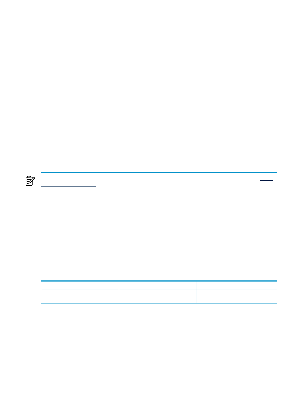
HP Virtual Connect technology
HP Virtual Connect (VC) is the preferred interconnect technology for HP BladeSystem environments. Virtual
Connect is used in place of traditional pass-through and managed switches to reduce costs and simplify
blade server connectivity to production LANs, SANs and converged networks. VC virtualizes I/O connections
by putting an abstraction layer between the servers and their external networks, so that LANs and SANs see
network interface (NIC) or host bus adapter (HBA) addresses presented by the VC modules instead of the
default burned-in interface addresses. Virtual Connect provides several key advantages:
• Reduces physical server-to-network cabling, complexity and leased network ports.
• Maintains constant end-to-end connections to preferred networks and fabrics.
• Enables administrators to wire LAN and SAN connections once and limit changes.
• Allows network assignments to be pre-provisioned even to empty server bays - enables rapid server
deployment and limits configuration errors.
• Separates server administration from LAN and SAN administration.
• Enables system administrators to be self-sufficient – add, replace, or modify servers in minutes to meet
changing workload and business requirements without impacting production networks.
• Relieves LAN and SAN administrators from server-centric maintenance.
The following figure compares traditional network connections to Virtual Connect technology.
Architectural overview 13
Page 14
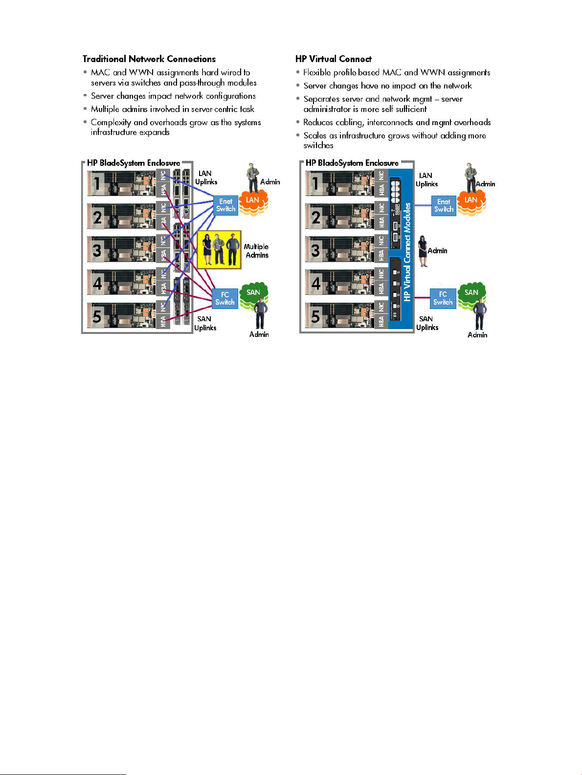
Figure 1-1 HP Virtual Connect technology
The Virtual Connect architecture is integrated into every BladeSystem c-Class enclosure and built on industry
standards, allowing operations with a broad range of switch brands that includes Cisco, Brocade, Juniper,
BNT and HP ProCurve. Virtual Connect functionality is delivered using high performance Virtual Connect
Ethernet and Fibre Channel modules that plug into the standard BladeSystem c-Class enclosure interconnect
bays. Each Virtual Connect module provides dense port aggregation that turns multiple physical network
connections to each server into a few simple high-speed uplinks that greatly reduce infrastructure complexity
and costs. To the external networks, Virtual Connect modules appear as regular pass-through devices, but
provide the benefits of integrated switching. HP BladeSystem enclosures configured with Virtual Connect
Ethernet and Fiber Channel modules are referred to as Virtual Connect domains. A VC domain is a logical
group that can be a single enclosure with up to 16 servers, or up to four physically linked enclosures running
to 64 servers.
To establish server connections to LANs and SANs, Virtual Connect uses server connection profiles in
combination with dynamic pools of unique media access control (MAC) addresses and world wide names
(WWN). A Virtual Connect server profile is a logical grouping of server connection attributes that can be
assigned to any bay in a BladeSystem enclosure. When assigned to an enclosure bay, the server in that
bay assumes the attributes of the profile which can include:
• MAC addresses for all NICs
• WWNs for all Host Bus Adapters (HBAs)
• Fibre Channel boot from SAN parameters
• Logical serial numbers
An important benefit of Virtual Connect is that server connection profiles and associated attributes are
assigned to BladeSystem enclosure bays and not hard wired to individual servers. The physical server in
each bay uses the MAC and WWN assignments in the bay profile instead of its default burned-in network
interface (NIC) or host bus adapter (HBA) addresses. Using this model, even if a server is replaced, the MAC
and WWN assignments for the enclosure bay remain constant, and the change is invisible to the network.
During Virtual Connect installation, the LAN and SAN administrators are still responsible for defining the
networks, subnets, and storage LUNs that the servers will use, but they no longer have to be involved in
every server-centric change. Once implemented, Virtual Connect allows system administrators to be more
14 Introduction
Page 15

self-sufficient, so they can add, replace, and modify servers in minutes without affecting LAN and SAN
availability or burdening network administration staff.
Managing HP Virtual Connect
To configure and manage Virtual Connect resources, HP provides options for both small and large Virtual
Connect environments.
HP Virtual Connect Manager
Virtual Connect Manager is a simple web console built into the firmware of each Virtual Connect Ethernet
module, and is designed to configure and manage a single Virtual Connect Domain.
Typical environment
Small environments with up to 4 Virtual Connect domains that have no plans to expand further.
HP Virtual Connect Enterprise Manager
VCEM is HP’s primary application that centrally manages server connections and provides workload mobility
for up to 250 Virtual Connect domains and thousands of servers across the datacenter.
Typical Environment
BladeSystem environments with more than one rack of enclosures . VCEM is designed to scale as the
infrastructure grows and simplifies the addition of new and bare metal enclosures. Small environments with
goals to expand beyond a single server rack should use VCEM from the very beginning to get the most
benefit.
• Medium to large HP BladeSystem environments that use Virtual Connect.
• HP BladeSystem environments that extend to multiple locations.
• Organizations that require centralized control of server-to-network connectivity.
• Organizations that require rapid server workload assignment and recovery across enclosures.
VCEM operations
VCEM aggregates network connection management and workload mobility for hundreds of Virtual Connect
domains and thousands of blade servers into a single console. This scalable solution delivers advanced
Virtual Connect management that builds upon and integrates with other HP management tools, including
HP Systems Insight Manager (HP SIM), Virtual Connect hardware, and the Onboard Administrator integrated
into HP BladeSystem c-Class enclosures. VCEM can be installed in a variety of configurations that include
a physical stand-alone console, as a plug-in to HP Systems Insight Manager, and as a virtual server guest.
The majority of VCEM operations are accessed through a dedicated homepage which includes the following
core tasks:
• Discover and import existing VC Domains without system downtime.
• Aggregate individual Virtual Connect address names for LAN and SAN connectivity into a centrally
administered VCEM address repository.
• Create VC Domain Groups.
• Assign and unassign VC Domains to VC Domain Groups.
• Define server profiles and link to available LAN and SAN network resources.
• Assign server profiles to BladeSystem enclosures, enclosure bays, and VC Domain Groups.
• Change, move, or automatically failover server profiles to spare servers.
• Rapidly install new bare-metal HP BladeSystem enclosures by assigning to a VC Domain Group.
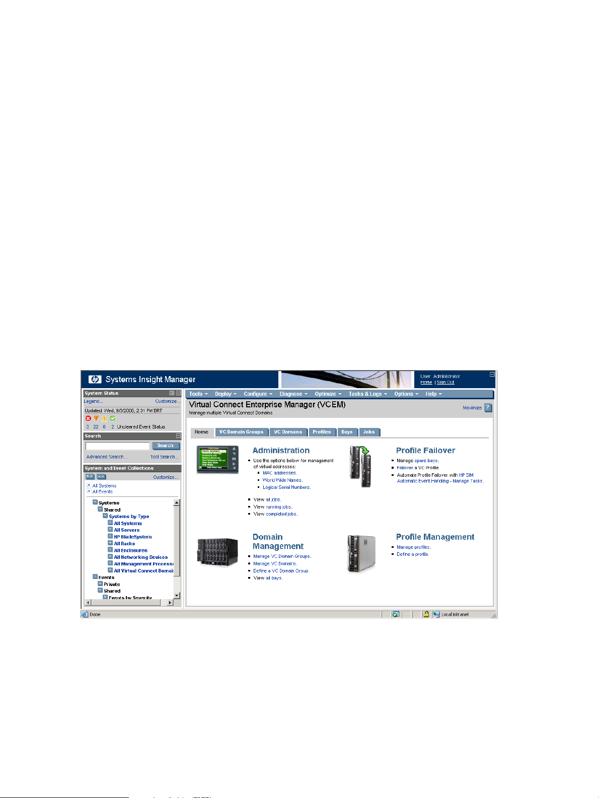
The following figure displays the Virtual Connect Enterprise Manager homepage.
Architectural overview 15
Page 16
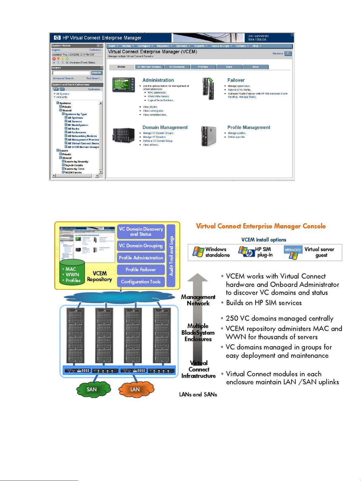
Figure 1-2 Virtual Connect Enterprise Manager homepage
The following figure summarizes the Virtual Connect Enterprise Manager architecture.
Figure 1-3 Virtual Connect Enterprise Manager architecture overview
Using VCEM, system administrators can quickly deploy, replace and recover servers and their associated
workloads by simply assigning or reassigning Virtual Connect server connection profile to an enclosure bay.
The example in the following figure illustrates a profile movement operation from “Server A” to “Server C”
using VCEM.
16 Introduction
Page 17
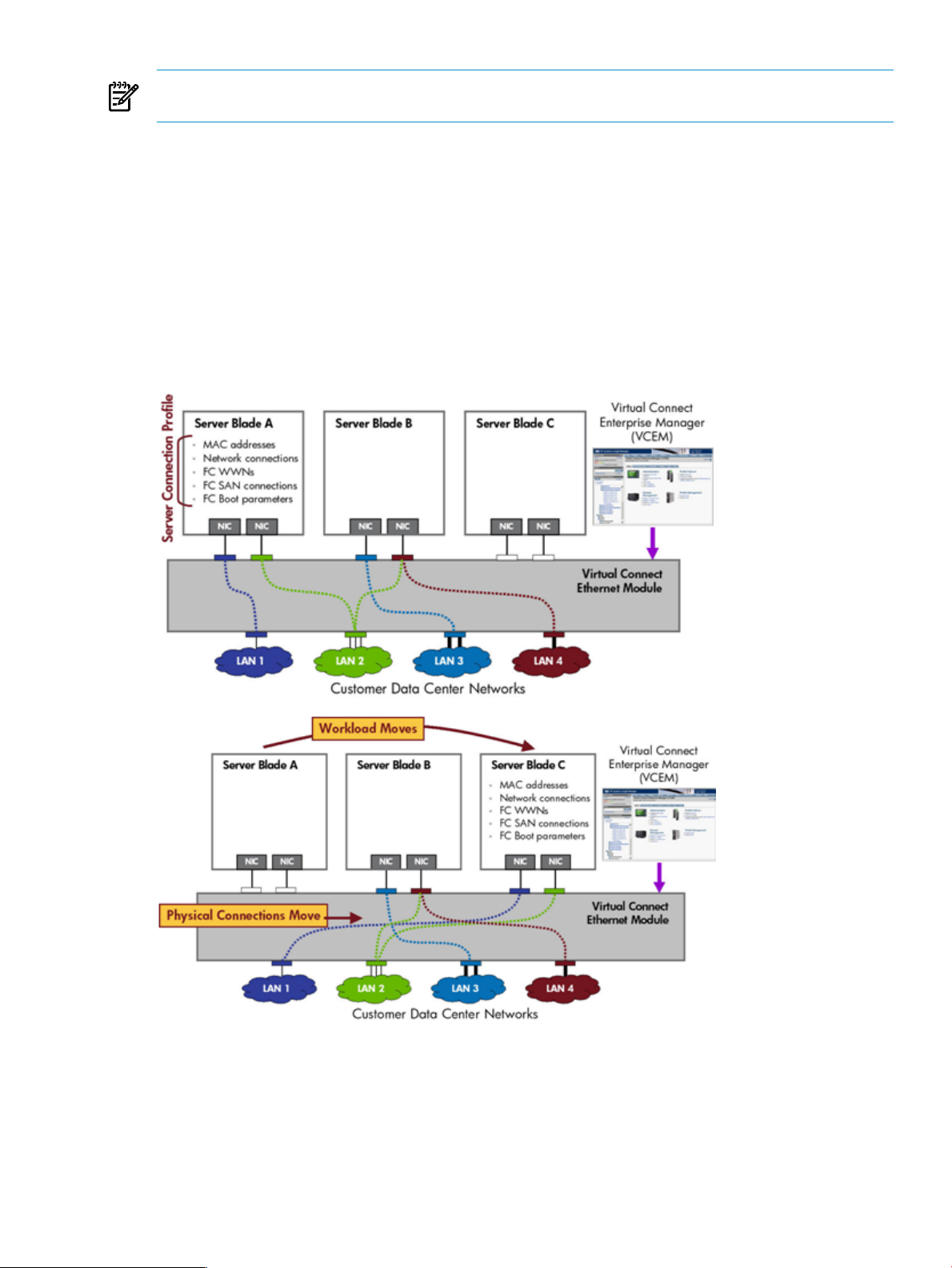
NOTE: The LANs associated with each uplink port and the attributes of the Virtual Connect server profile
remain exactly the same; only the location of the profile has changed.
When a Virtual Connect server connection profile is moved, the associated MAC, WWN, boot from SAN
parameters and related workload always move with the profile.
From the VCEM GU,I server profiles can be moved manually or scripted using the profile failover capability
to a user-defined spare server. A server profile can be moved within the same VC Domain or to any other
Domain in the same Virtual Connect Domain Group, whether it is in the same rack, across the datacenter
or at another location. The profile movement and failover functionality provided by VCEM can be used to
provide cost-effective server blade recovery, perform proactive hardware maintenance with reduced
downtimes, and control rapid server repurposing to meet changing workload and application priorities.
When moving Virtual Connect server profiles, the fastest completion times are achieved when the
corresponding source and target servers are configured to boot-from-SAN. The automated profile failover
functionality delivered in VCEM requires a boot-from-SAN environment.
Figure 1-4 VC profile movement example
Setup and configuration summary
To set up and configure VCEM into an existing HP BladeSystem environment running Virtual Connect:
Setup and configuration summary 17
Page 18

1. Verify that the Virtual Connect module and HP Onboard Administrator firmware for all VC Domains to
be managed by VCEM meets the minimum requirements. For a complete list of hardware, firmware,
and software requirements, see Installing and configuring VCEM..
2. Install the VCEM software on a host system running a supported operating system using the HP Insight
Software DVD.
Insight Software media can be downloaded from http://www.hp.com/go/insight.
HP recommends that you use Insight Software media installation wizard to ensure the correct installation,
compatibility, and operation of all required components.
3. Log on to the VCEM console, and discover the VC Domains to be imported into VCEM by entering the
corresponding Onboard Administrator IP addresses.
4. Apply a VCEM license to each VC Domain enclosure to be managed. A VCEM license enables operations
across all bays in an enclosure for the life of the enclosure. See Product licensing in this chapter for a
full list of license options.
5. From the VCEM console, create one or more VC Domain Groups, and assign the corresponding VC
Domains.
• The configuration of the first domain in a VC Domain Group defines the characteristics for all
subsequent group members.
• All domains in a VC Domain Group have the same Virtual Connect moduleconfiguration and
network uplink connections.
After you complete these steps, VCEM is ready to manage your Virtual Connect infrastructures. You can now
add, change, and move blade servers connections and workloads across the data center in minutes.
18 Introduction
Page 19

2 Installing and configuring VCEM
This chapter describes how to install and configure VCEM.
IMPORTANT: This guide assumes that you have previously installed Virtual Connect using the integrated
Virtual Connect Manager, have read the
understand its concepts.
Preparing for a VCEM installation
If you have VCEM 1.10 or earlier, you must first upgrade to VCEM 1.20 or later using the HP Insight Software
DVDs to ensure the correct installation, compatibility, and operation of all components. VCEM 6.1 can be
installed as a new application or used to directly update installations of VCEM 1.20, 1.3x, 1.40, and 6.0
.
IMPORTANT: HP recommends that you install and upgrade VCEM using the HP Insight Software DVDs. If
you manually upgrade Systems Insight Manager 6.0 to 6.1, you must also upgrade VCEM to an HP Insight
Software compatible version.
Installation prerequisites
This section describes the hardware and software prerequisites for installing VCEM and related components.
For a full list of Insight Software requirements see the
HP Virtual Connect for c-Class BladeSystem User Guide
HP Insight Software Support Matrix
, and
.
Hardware requirements
The following table lists the Insight Software Insight Control CMS hardware installation requirements.
Servers
Memory
Disk space
Software requirements
The following table lists operating systems and related components that are required to install and operate
VCEM v6.1.
SpecificationComponent
HP ProLiant BladeSystem c-Class or p-Class server blades, HP
ProLiant ML or DL 300, 500, and 700 G3 or later recommended
to host HP Systems Insight Manager and VCEM.
At least 4 GB RAM recommended). If you are installing HP Insight
Dynamics software, 6-8 GB is recommended.
Minimum 1.6 GHz (2 GHz or faster recommended).Processor
At least 10 GB for HP Systems Insight Manager, VCEM, and
database storage. Additional space is needed for storing more
comprehensive Insight Software configurations that include server
deployment and other Insight Software plug-ins.
New Technology File System (NTFS)File structure
Local or mapped DVD drive required for software installationDVD
SpecificationComponent
Operating Systems
• Microsoft Windows Server 2003 Standard and Enterprise
Editions SP2 (x86 and x64)
• Microsoft Windows Server 2003 R2, Standard and Enterprise
Editions SP2 (x86 and x64)
• Microsoft Windows Server 2008 Standard and Enterprise
Editions SP2 (x86 and x64)
• Microsoft Windows Server 2008 R2 Standard and Enterprise
Edition SP2 (x64)
Preparing for a VCEM installation 19
Page 20

Hypervisor Guests
• Microsoft Windows Server 2008 Hyper-V SP2
• Microsoft Windows Server 2008 R2 Hyper-V
• Microsoft Hyper-V Server 2008 SP2
• Microsoft Hyper-V Server 2008 R2
• VMware ESX 3.5 Update 5
• VMware ESX 4.0 Update 1
Services
Browsers
Database
Virtual Connect requirements
The following Virtual Connect hardware and firmware is supported by VCEM v6.1.
Virtual Connect Ethernet modules
• NET 3.0 Framework or later
• Simple Network Management Protocol (SNMP)
• TCP/IP with DNS
• Microsoft iSCSI Software Initiator 2.06, 2.07 or 2.08
• iSCSI 6.0.6001.18000 (Only required for iSCSI environments)
• Mozilla Firefox 3.x
• Microsoft Internet Explorer v7.0
• Microsoft Internet explorer v8.0 (compatibility mode)
• Microsoft SQL Server 2008 Standard or Enterprise SP1
• Microsoft SQL Server 2008 Express SP1
• Microsoft SQL Server 2005 SP3
• Microsoft SQL Server 2005 Express Edition SP3
SpecificationComponent
• HP Virtual Connect 1/10 Gb Ethernet Module
• HP Virtual Connect 1/10 Gb-F Ethernet Module
• HP Virtual Connect Flex-10 10 Gb Ethernet Module
Virtual Connect Fibre Channel modules
Virtual Connect firmware
Managed servers
The following HP BladeSystem c-Class servers are supported by VCEM v6.1 as managed nodes.
• HP Virtual Connect 4 Gb Fibre Channel Module
• HP Virtual Connect 8 Gb 24-port Fibre Channel Module
• HP Virtual Connect 8 Gb 20-port Fibre Channel Module
• Virtual Connect firmware v2.1x and later (full feature support)
• Virtual Connect firmware v3.0x (full feature support)
• Operations compatibility for Virtual Connect firmware v3.x
(limited feature support)
SpecificationComponent
20 Installing and configuring VCEM
Page 21
• HP ProLiant BL260c
• HP ProLiant BL2x220c
• HP ProLiant BL460c
• HP ProLiant BL465c (G7 model supported only with Virtual
Connect Flex-10)
• HP ProLiant BL480c
• HP ProLiant BL490c
• HP ProLiant BL495c
• HP ProLiant BL680c
• HP ProLiant BL685c (G7 model supported only with Virtual
Connect Flex-10)
• HP ProLiant xw460c Blade Workstation
HP BladeSystem Integrity server
Installing VCEM
For server prerequisites for VCEM installation, including hardware and software prerequisites, see Installation
prerequisites or the
IMPORTANT: VCEM 6.1 supports the Microsoft Internet Explorer 8 (IE8) browser, but the underlying Virtual
Connect Manager only supports IE8 in IE7 compatibility mode. Using IE8 to perform VCEM Domain
Maintenance tasks that access Virtual Connect Manager might result in failed or incomplete operations. HP
recommends Microsoft Internet Explorer 7 (IE7) or Firefox 3.x as the preferred browsers for use with VCEM.
For a list of browsers supported by Virtual Connect Manager, see the
BladeSystem User Guide
When you are upgrading to a new and different CMS, or are moving to a 64-bit CMS, then you might need
to migrate your data by using the Systems Insight Manager data migration tool. If you are upgrading to a
new version of VCEM on the same CMS, data migration with the Systems Insight Manager data migration
tool is not necessary. For more information, see the
Guide for Microsoft Windows
To install VCEM, follow the steps provided in the installation wizard. To access online help, click the ? icon
in the upper right-hand corner of the window.
HP Insight Software Support Matrix
.
HP Systems Insight Manager Installation and Configuration
.
• HP Integrity BL860c / 860c i2
• HP Integrity BL870c / 870c i2
• HP Integrity BL890c i2
.
HP Virtual Connect for c-Class
Removing VCEM
WARNING! Removing VCEM could have significant implications. Before removing VCEM, verify that no
other upper level management products such as HP Insight Dynamics - VSE are using VCEM capabilities.
Uninstallation of VCEM requires a release of all VC Domains. Removing VCEM also removes all VCEM-centric
historical tracking of individual WWNs and MAC addresses.
IMPORTANT: Before you remove VCEM, ensure that you have removed all VC Domains from the VC
Domain Groups that are under VCEM control. Otherwise, VCEM removal will not be successful. For more
information see “Removing a VC Domain from a VC Domain Group.”
Choose from one of the following options:
• Select Start→All Programs→HP Insight Software→Uninstall HP Insight Software and select HP
Virtual Connect Enterprise Manager.
• From the Control panel, click Add or Remove Programs, select HP Insight Software, and click HP
Virtual Connect Enterprise Manager.
Installing VCEM 21
Page 22

1. Confirm the removal.
After removing HP Virtual Connect Enterprise Manager, some files might not be removed. Manually
removing such files might cause an access denied error message. If this occurs, reboot the server
where VCEM is installed, and then remove the files.
2. The removal operation does not remove the following VCEM folder.
C:\Program Files\HP\Virtual Connect Enterprise Manager\
The VCEM folder does not cause any system damage or prevent VCEM from future reinstallation.
3. The removal logs are located in %systemdrive%\HPIC\logs\<timestamp> folder. The
%systemdrive% is the drive where the operating system is installed (such as C:) and the <timestamp>
identifies the system clock timestamp.
Performing post-installation configuration tasks
Post-installation configuration tasks
If you are installing VCEM for the first time, perform the following tasks:
1. To access VCEM, select either of the following:
• Start→All Programs→HP Virtual Connect Enterprise Manager→HP Virtual Connect
Enterprise Manager
• HP SIM→Tools→Integrated Consoles→Virtual Connect Enterprise Manager (VCEM)
If VCEM is a stand-alone installation, click the VCEM desktop icon. The VCEM Home page appears.
2. Enter the credentials that you entered when performing the installation. The VCEM home page appears.
• If an HP SIM discovery has been performed, all Virtual Connect modules appear.
• If an HP SIM discovery has not been previously performed, and no Virtual Connect modules appear,
perform an HP SIM discovery before continuing.
1. Make sure to discover the Onboard Administrator IP addresses with enclosures that have VC
Ethernet modules.
2. To verify whether any VC Domains have been discovered, click the VC Domains tab.
For more information about performing an HP SIM discovery, see the
3. (Optional) If you are installing VCEM as part of the HP Insight Software suite, after performing an HP
SIM discovery, access the HP Managed System Software Wizard and complete the steps in the wizard.
For more information about the wizard, see the
Guide.
NOTE: VCEM 6.1 does not support VC firmware 1.3x , 1.2x or 2.0x. If you have these versions of
VC firmware, an incompatible firmware icon is displayed and VCEM may prevent some VC domain,
VC domain group, and server profile operations. You must upgrade to at least 2.1x. See Upgrading
incompatible firmware modes and versions for more information. While VCEM does not support these
HP Insight Software Installation and Configuration
HP SIM User Guide
.
22 Installing and configuring VCEM
Page 23

older firmware versions, both VCEM and the HP Management System Software Wizard will not prevent
you from licensing these older firmware versions.
4. (Optional) Configure the MAC addresses to match the needs in the data center.
a. From the VCEM Home page, click the Home tab. In a stand-alone VCEM installation, to return to
the Home page, click the Home link on the upper right-hand corner of the screen.
b. Click the MAC Addresses hyperlink.
c. To create a custom range, click Add custom.
The MAC address range used by the VCEM domain must be unique within the environment. HP
provides a set of predefined ranges that are reserved for use by Virtual Connect and VCEM, and
does not conflict with server factory-default MAC addresses.
When using the HP-predefined MAC address ranges, be sure that each range is used only once
within the environment.
For more information, see Adding custom MAC address ranges.
5. (Optional) Create MAC exclusion ranges. For more information, see Creating MAC exclusion ranges.
6. (Optional) Configure the World Wide Names ranges to meet your requirements.
a. From the VCEM Home page, click the Home tab. In a stand-alone VCEM installation, to return to
the Home page, click the Home link on the upper right-hand corner of the screen.
b. Click the World Wide Names hyperlink.
c. To create a custom range, click Add custom.
The WWN range used by the VCEM domain must be unique within the environment. HP provides
a set of predefined ranges that are reserved for use by Virtual Connect and VCEM, and does not
conflict with server factory-default WWNs.
When using the HP-predefined WWN ranges, be sure that each range is used only once within
the environment.
For more information, see Adding custom WWN address ranges.
7. (Optional) Create WWN exclusion ranges. For more information, see Creating WWN exclusion ranges.
8. Click the VC Domains tab. VC Domains appear as the following:
• Unconfigured VC Domains—Appear as VCD_name, where name is the temporary name
automatically given to the VC Domain.
• Configured VC Domains—Appear with the VC Domain name.
9. Select a VC Domain, and then click License to license the domain. For more information on licensing,
see Licensing an enclosure for VCEM.
10. Create a new VC Domain Group, and then add one or more already licensed VC Domains to it. For
more information on creating a new VC Domain Group, see Creating a VC Domain Group.
You can continue using VCEM and its additional functions such as creating profiles and assigning them to
bays.
VCEM uses a Secure Sockets Layer (SSL) connection provided by HP SIM. For more information about the
available cipher suites and how to enable or disable them, see the
paper at http://h18013.www1.hp.com/products/servers/management/hpsim/infolibrary.html.
VCEM uses the same TCP ports as HP SIM. VCEM does not open any other TCP ports.
Upgrading incompatible firmware modes and versions
If unsupported VC Domain firmware versions are detected at the end of an VCEM 6.1 upgrade, a warning
message similar to the following is displayed:
Virtual Connect Enterprise Manager (VCEM) detected there is one or more VC
Domain Group running on an unsupported firmware mode during the upgrade. VCEM
has marked all affected VC Domain Group(s) and VC Domain(s) with an incompatible
status. VCEM 6.1 will be unable to perform server profile operations that
belong to these marked VC Domains.
Understanding HP SIM security
white
Performing post-installation configuration tasks 23
Page 24
Upgrade to a supported VC firmware by performing the following steps:
1. Select the VC domain with an incompatible status and click VC Domain Maintenance.
2. Upgrade the managed VC Domains to the minimum VCEM 6.1 supported VC firmware version. See
the HP Insight Software Support Matrix for the VCEM supported VC firmware versions.
3. Click Complete VC Domain Maintenance to close the operation.
4. Upgrade the VC Domain Group firmware mode to the minimum VCEM supported VC firmware.
VCEM home page
Virtual Connect Enterprise Manager uses a dedicated graphical user interface to access and control Virtual
Connect operations, which includes the following core tasks:
• Discovers and imports existing VC Domains without system downtime.
• Assigns and administers connection addresses for LANs (MAC) and SANs (WWN) from a centrally
address repository.
• Creates VC Domain Groups.
• Assigns and unassigns VC Domains to VC Domain Groups.
• Defines server profiles and links to available LAN and SAN network resources.
• Assigns server profiles to BladeSystem enclosures, enclosure bays, and VC Domain Groups.
• Changes, moves , or automatically fails over server profiles to spare servers.
• Rapidly installs new bare-metal HP BladeSystem enclosures by assigning to a VC Domain Group.
The following screenshot shows the VCEM home page.
Figure 2-1 VCEM home page
24 Installing and configuring VCEM
Page 25
3 Managing VC Domains
VC Domains
This section describes how to use VCEM to manage VC Domains.
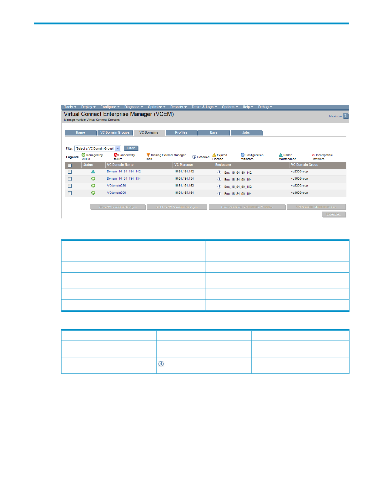
On the VC Domains page, you can filter the VC Domain list by VC Domain Group. The default filter shows
all VC Domains.
Figure 3-1 VC Domains page
The following table lists and describes the columns on the VC Domains page.
DescriptionItem
Describes VC Domain statusStatus
Identifies the VC Domain nameVC Domain Name
VC Manager
Identifies the domain IP address for the primary VC Ethernet
module
Identifies the enclosure nameEnclosure
Identifies the VC Domain Group name, if anyVC Domain Group
The following table lists and describes VC Domain status icons and descriptions.
DescriptionIconStatus
(no icon)Not licensed
Licensed
The VC Domain enclosures have not been
licensed.
The VC Domain enclosures have been
licensed to VCEM.
VC Domains 25
Page 26
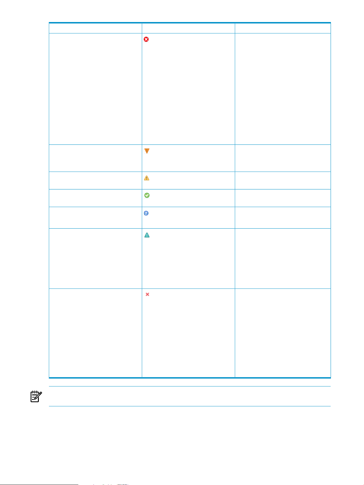
DescriptionIconStatus
Connectivity failure
Missing external manager lock
Expired license
Managed by VCEM
Configuration mismatch
Failed to connect to the VC Domain. Possible
causes include:
• Connection times out.
• Ethernet VC Module is physically not
available.
• Virtual Connect Manager is failing.
• VC Domain firmware is updating.
• HP Virtual Connect Ethernet IP address
has changed (through DHCP or EBIPA
configuration).
VCEM checks the VC Domain connectivity
before executing any operation that involves
Virtual Connect Manager. VCEM omits the
VC Domains with connection failure
status message when executing an
operation.
VCEM is unable to obtain the necessary
permissions for External Manager user.
VCEM might have lost the External Manager
lock at the VC Domain.
The VC Domain enclosure has an expired
license.
The VC Domain is part of a VC Domain
Group and operating normally.
The VC Domain configuration has changed
and does not match the VC Domain Group
configuration.
Under maintenance
Incompatible firmware
NOTE: For information on how to resolve status issues, see the
Guide
.Troubleshooting.
VC Domain is unlocked for domain, network,
and storage changes through Virtual
Connect Manager. After completing the
domain, network, and storage changes,
confirm the new VC Domain configuration
in VCEM. VCEM operations related to this
VC Domain or its VC Domain Group, such
as create profile, move profile, profile
failover, and so on, are blocked while the
VC Domain is under maintenance.
This status is displayed after a VCEM
upgrade and indicates that an incompatible
firmware mode and version was detected.
Only the following VCEM VC domain
operations are permitted for resources with
an incompatible status:
• Remove VC Domain from Group
• Delete VC Domain Group
• Perform VC Domain Maintenance
• Upgrade Group Firmware Mode
See Upgrading incompatible firmware
modes and versions to upgrade to a
supported firmware.
HP Virtual Connect Enterprise Manager User
To display the properties of a particular VC Domain, click the VC Domain name. Properties include the
primary IP address, status, Virtual Connect firmware version, Ethernet networks, Shared Uplink sets, Fibre
Channel SAN fabrics, Ethernet and Fibre Channel common settings, and SNMP Ethernet and Fibre Channel
alert destinations.
26 Managing VC Domains
Page 27

Requirements for adding a VC Domain to a VC Domain Group
To add a configured VC Domain to a VC Domain Group, the following requirements must be met:
• The VC Domain must have the minimum number of enclosures required by the VC Domain Group. For
more information, see Working with multienclosure VC Domains.
• VC Domain names must not already exist in VCEM.
• Profile names must not already exist in VCEM.
• MAC or WWN addresses or serial numbers that are assigned to a profile must not be in use by VCEM
or in a VCEM exclusion list. If the MAC or WWN addresses or serial numbers are user-defined, then
you must define an address range in VCEM.
• If the VC Domain contains server profiles, the MAC addresses, WWNs, and the serial numbers allocated
must be compatible with the MAC, WWN, and serial number range types of the VC Domain Group:
• A VC Domain containing server profiles with factory-default addresses can be added to a VC
Domain Group with VCEM-defined range types, and user-defined range types. To add a VC
Domain to a VC Domain Group with factory-default range types, all profiles of the VC Domain
must be configured with factory-default addresses.
NOTE: Keep the following upgrade requirements in mind:
• After upgrading from VCEM 1.20 or 1.3x to VCEM 6.1, VC Domain Groups that were using
HP-predefined ranges for MAC and WWN addresses will start using VCEM-defined ranges
for new server profiles. VCEM 6.0 and later does not use HP-predefined ranges for MAC
and WWN addresses.
• If the VC Domain or VC Domain Group screen displays an incompatible firmware status after
upgrading from an older VCEM version, upgrade the VC firmware for the affected VC
Domains in order to make changes. See Upgrading incompatible firmware modes and
versions for more information.
• A VC Domain containing server profiles with addresses allocated as user-defined range type can
be added to a VC Domain Group with a user-defined or VCEM-predefined range type. A
user-defined (custom) MAC and WWN range that includes all addresses allocated to server profiles
within the VC Domain must be defined in VCEM before adding the domain to the VC Domain
Group.
• A VC Domain containing server profiles with addresses allocated as HP-predefined range type
can be added to a VC Domain Group with an VCEM-predefined or a user-defined range type.
• An unconfigured VC Domain without server profiles has no range type restrictions when adding
in a VC Domain to a VC Domain Group.
The following table summarizes MAC address, WWN address, and serial number range type compatibility
when adding a VC Domain to a VC Domain Group.
VC Domain has profiles with MAC or WWN
addresses or serial number allocated as
user-defined
user-defined
Domain Group
VCEM-supportedMAC or WWN or serial number in VC
YesVCEM-defined or user-definedVCEM-defined
YesVCEM-defined or user-definedUser-defined
YesFactoryFactory (MAC address or WWN address)
YesVCEM-defined or user-definedFactory
YesVCEM-defined or user-definedVCEM-defined, HP-predefined, or
NoFactoryVCEM-Defined, HP-predefined, or
VC Domains 27
Page 28

VC Domain configuration must be identical to the VC Domain Group configuration. Verify that the following
items are identical:
• Interconnect bays location and model
• Enclosure model
• Domain settings:
Configuration for double density servers (for example, BL2x220c)•
• Configuration for full-height and half-height single density servers (for example, BL460c, BL480c)
• Ethernet settings:
MAC Cache Failover:•
• Enable Fast MAC Cache Failover
• MAC Refresh Interval
• IGMP Snooping:
Enable IGMP Snooping•
• IGMP Idle Timeout Interval
• Server VLAN Tagging support:
Tunnel VLAN Taggings or Map VLAN Taggings•
• Force Server connection setting
• Multiple Network Speeding Settings:
Preferred Link Connections•
• Preferred Link Connection Speed
• Maximum Link Connection
• Maximum Link Connection Speed
• Network SNMP settings:
• Read Community
• System Contact
• IP addresses
• Fibre Channel SAN Fabric settings:
Enables SMI-S•
• Fibre Channel SNMP settings: Read Community, System Contact, and IP addresses
• Network and Fibre Channel SAN Fabrics uplinks
• For each single network uplink:
Network name•
• Smart link
• Private Network
• Enable VLAN Tunneling
• State
• Network port location
• Speed/duplex mode
• Connection mode
• Preferred Link Connection
• Preferred Link Connection Speed
28 Managing VC Domains
Page 29

• Maximum Link Connection
• Maximum Link Connection Speed
• Number of networks configured in the VC Domain
• For each shared network uplink:
Uplink set name•
• Network port location
• Speed/duplex mode
• Connection mode
• Number of VLANs tagged associated to the shared network uplinks
• Number of shared networks configured in the VC Domain
• For each VLAN-tagged associated to the shared network uplink:
Network name•
• Network state
• VLAN ID
• Native
• Smart Link
• Private network
• Preferred Link Connection
• Preferred Link Connection Speed
• Maximum Link Connection
• Maximum Link Connection Speed
• For each Fibre Channel SAN Fabric:
Fabric name•
• If the VC Domain has firmware 2.1x and later:
• Configuration speed
• Fabric port location
• Number of Fibre Channel SAN Fabrics configured in the VC Domain
To add an unconfigured VC Module to a VC Domain Group, the following items must be identical:
• Interconnect bays location and model
• Enclosure model
• Uplinks of the network and Fibre Channel SAN Fabric
• Power state of the VC Modules
Mixed Virtual Connect firmware versions and firmware compatibility in a VC Domain Group
VCEM enables firmware compatibility using current and future versions of Virtual Connect firmware. This
feature provides these benefits:
• A single VC Domain Group can contain VC Domains running different firmware versions. The following
table shows the supported combinations of Virtual Connect firmware within a single VC Domain Group.
VC firmware mode 2.1xVC firmware mode 2.3xVC firmware mode 3.0xVC Domain Group
1
YesVC Domain firmware 3.0x
Yes
YesNoVC Domain firmware 2.3x
Yes
Yes
YesNoNoVC Domain firmware 2.1x
1
2
VC Domains 29
Page 30

1 Virtual Connect 3.0x features must be disabled for VC Domains to be in the same group as Virtual Connect 2.1x or 2.3x.
2 Virtual Connect 2.3x features must be disabled for VC Domains to be in the same group as Virtual Connect 2.1x.
NOTE: If you have a VC Domain Group 2.1x and all the VC Domains have been upgraded to Virtual
Connect 2.3x, the group will not automatically function as a VC Domain Group 2.3x.
To enable Virtual Connect 2.3x functionality, see Upgrading VC Domain Group Firmware Mode.
• VCEM 6.1 might be able to support future versions of Virtual Connect firmware in a compatibility mode.
This compatibility mode enables a new Virtual Connect firmware version to be used immediately with a
VCEM 6.1 installation. For example, if Virtual Connect released a 3.1x version of its firmware, a VC Domain
within a 3.0x VC Domain Group could be upgraded to the 3.1x version of the firmware while preserving
the 3.0x level of functionality. The VC Domain Group will operate at the firmware version with which it was
created. A subsequent VCEM release would support the new functionality.
Virtual Connect 3.0x features that must be disabled in a VC Domain to be part of the VC Domain Group with Virtual Connect firmware 2.1x and 2.3x
NOTE:
Keep the following in mind:
• VC 3.0x features must be disabled in order for the firmware to reside in the same groups as VC 2.3x
or 2.1x firmware versions.
• All Virtual Connect 2.3x features not supported by VC firmware 2.1x must be disabled.
• To disable any of the FC SAN 3.0x features, the last connection in the feature table must be deleted
first.
• Multi-blade FC servers are not supported.
Do not configure server profiles assigned to multi-blade servers with more FC SAN connections than
the number of Virtual Connect Fibre Channel modules available in the VC Domain. The additional FC
SAN Connections Connected To column displays duplicate bays.
To disable this feature:
1. Log on to HP Virtual Connect Manager.
2. Expand Server Profiles in the navigation pane and select the server profile with the additional
FC SAN Connections that you want to delete.
3. Right-click and select Delete Connection.
• More than 32 Ethernet network connections in a server profile is not supported.
To disable this feature:
1. Log on to HP Virtual Connect Manager.
2. Expand Server Profiles in the navigation pane and select the server profile with more than 32
Ethernet network connections.
3. Right-click on the last Ethernet connection and select Delete Connection as displayed in the
following figure:
30 Managing VC Domains
Page 31

Figure 3-2 Server profiles with more than 32 Ethernet network connections
4. Continue selecting and deleting the last connection until you have a total amount of 32 Ethernet
connections.
Virtual Connect 2.3x features that must be disabled in a VC Domain to be part of the VC Domain Group with Virtual Connect firmware 2.1x
• Enhanced SNMP configuration is not supported.
Figure 3-3 Enhanced SNMP configuration
VC Domains 31
Page 32

Do not configure the VC Domain using the enhanced SNMP configuration. If necessary, disable the
enhanced SNMP configuration by following these steps:
1. Do not configure more than five SNMP trap destinations.
2. Verify that all SNMP trap destinations follow these rules:
a. The Destination Name must be in the following format:
<IP Address of the SNMP Trap Destination>_<Community String>_<0 for
VC-Enet and 1 for VC-FC>
(for example, 192.168.1.1_public_1)
b. Select the “ipv4” option.
c. Set the SNMP trap format to “SNMPv1.”
Figure 3-4 Adding or editing a compatible SNMP trap destination
d. To disable trap severities, from the Add a SNMP Trap Destination page, click Advanced, as
shown in the following figure.
Figure 3-5 Disabling trap severities
e. Trap categories must equal Other for either VC-Enet traps or VC-FC traps. Do not select both.
From the Add a SNMP Trap Destination page, click Advanced, click More, and then select
either of the following:
• On the VC-Enet Traps box, select Other, as shown in the following figure.
• On the VC-FC Traps box, select Other.
32 Managing VC Domains
Page 33

Figure 3-6 Selecting trap categories
f. To disable Virtual Connect Manager traps, from the Add a SNMP Trap Destination page,
click Advanced, and then click More. The right side must be empty, as shown in the following
figure.
Figure 3-7 Disabling Virtual Connect Manager traps
3. Do not modify the SNMP configuration for VC Domain level. The default SNMP configuration for
VC Domain level is Enabled with the Community String equaling Public. This is only available
through the Virtual Connect Manager Command line interface.
• Fibre Channel Port Speed cannot be set to 8Gb for a HP Virtual Connect 8-Gb 20-Port Fibre Channel
Module.
Select any value other than 8Gb as the uplink configuration speed when defining a SAN Fabric for a
HP Virtual Connect 8-Gb 20-Port Fibre Channel Module.
VC Domains 33
Page 34

Figure 3-8 Select any value other than 8Gb as uplink and downlink configuration speeds
Select any value other than 8Gb as the downlink configuration speed when assigning a SAN Fabric
for a HP Virtual Connect 8-Gb 20-Port Fibre Channel Module.
VC Domain tasks
From the VC Domains page, you can perform the following tasks:
• License an enclosure for VCEM
• Create a VC Domain Group
• Add a VC Domain to a VC Domain Group
• Remove a VC Domain from a VC Domain Group
• VC Domain Maintenance
• Cancel VC Domain Maintenance
• Resynchronize a VC Domain with Configuration Mismatch Status
Licensing an enclosure for VCEM
You must purchase a license for each enclosure to be managed. For licensing information, see the VCEM
QuickSpecs at http://www.hp.com/go/vcem.
To enable a VC Domain license, select from one of the following options:
• For new VC Domain Groups:
Click New VC Domain Group from the VC Domain page. An area showing both licensed and
1.
unlicensed VC domains is displayed.
2. Click Add Key and enter the key string.
NOTE: Add Key is always enabled.
3. Click one or more unlicensed VC Domains.
4. Click Apply License.
5. Click OK to validate the key string. If the key string or format is valid, the key is added to HP SIM.
6. Click Next to provide VC Domain credentials.
• For existing VC Domain groups:
34 Managing VC Domains
Page 35

Select the VC Domain from the VC Domain page and click License. The License Enclosure page
1.
is displayed.
2. Click Add Key.
3. Enter the license key string, and then click OK. If the license key is valid, it is added to HP SIM.
The License Enclosure page reappears displaying the number of available licenses
4. Select the VC Domain to which you want to apply the VCEM license.
5. Click Apply License.
6. The VC Domain list page reappears, displaying the updated status of VC Domains.
7. The VC Domain appears with Informational status.
Creating a VC Domain Group
You can create a VC Domain Group by selecting the VC Domains that you want to incorporate into a new
VC Domain Group.
IMPORTANT: This VCEM operation does not provide a reference to the VC Domain from HP SIM. To access
this reference, you must correlate the HP SIM and Virtual Connect logs. For more information, see Correlating
VCEM operations in HP SIM and Virtual Connect logs.
VCEM supports multienclosure VC Domains. A multienclosure VC Domain is a VC Domain with one local
enclosure and up to three remote enclosures.
To manage multienclosure VC Domains in VCEM, you must perform the following steps before you create
a VC Domain Group:
1. Log in to Virtual Connect Manager.
2. Find and import a local enclosure, and then select the appropriate Double-dense option.
3. Skip the Network and Fibre Channel configuration wizards, and then navigate directly to the VC Domain
user interface.
4. Find and import the necessary remote enclosures in the correct order through Virtual Connect Manager.
5. Go to HP SIM and perform a manual discovery for the Onboard Administrator IP address of all released
VC Domain enclosures.
VCEM cannot manage a VC Domain that has one or more FC modules in an Incompatible state.
The FC module can become incompatible in the following situations:
• An HP Virtual Connect 4Gb FC module replaces an HP Virtual Connect 8Gb 24-port FC module.
• An HP Virtual Connect 8Gb 24-port FC module replaces a HP Virtual Connect 4Gb FC module.
• If HP Virtual Connect 8Gb 24-port FC modules and HP Virtual Connect 4Gb FC modules share the
same IO bay slice. (For example, a HP Virtual Connect 4Gb FC module in IO Bay 3 and a HP Virtual
Connect 8Gb 24-port FC module in IO Bay 4).
• In a multienclosure VC Domain, if there are mixed HP Virtual Connect 4Gb FC modules and HP Virtual
Connect 8Gb 24-port FC modules in the same IO bay from different enclosures. (For example, 4Gb
FC modules in the local enclosure, but 8Gb FC modules in the remote enclosures.)
To create a VC Domain Group from the VC Domains page, select the VC Domains:
1. Click New VC Domain Group.
(Optional) If the enclosures related to the selected VC Domains are not licensed to VCEM, then the
License page appears below the VC Domains list. For more information, see Licensing an enclosure for
VCEM. Otherwise, the Create VC Domain Group appears below the VC Domains list.
VC Domains 35
Page 36

(Optional) You can provide a new name for the unconfigured VC Domains. Valid VC Domain Group
names are alphanumeric, hyphens (-), underscore (_), and cannot exceed 64 characters.
2. Enter the username and password for each VC Domain. Ensure you provide VC Domain credentials
with full privileges. VC Domains appear as:
• Unconfigured domains, which appear in the System Name column with the unassigned name,
VCD_name
• Configured domains, which appear in the System Name column with their previously assigned
name
3. Enter the username and password for the Onboard Administrator of each unconfigured VC Domain.
Ensure you provide the Onboard Administrator credentials with full privileges if the Virtual Connect
Module is not configured.
(Optional) In some cases you might want to overwrite the existing VC Domain configuration for selected
VC Domains. To enable this action, select Existing VC Domain configuration settings for selected
VC Domain(s) without server profiles will be overwritten by selected base VC Domain
configuration defined for the VC Domain Group. In this case, VCEM validates that the selected VC
Domain configurations match the VC Domain Group configuration. VC Domains that are already
configured and have server profiles are not affected.
4. Enter the VC Domain Group name in the VC Domain Group Name field. Valid VC Domain Group
names are alphanumeric, hyphens (-), underscore (_), and cannot exceed 64 characters.
5. From the Configuration based on VC Domain list, select the VC Domain configuration upon which the
new VC Domain Group is to be based. The Configuration VC Domain list contains only configured VC
Domains.
6. From the Select MAC range type list, select whether the MAC address range type is VCEM-defined,
user-defined, or factory-default. You can only select the User-Defined option for MAC range type if a
MAC custom range is defined.
7. From the Select WWN range type list, select whether the WWN address range type is VCEM-defined,
user-defined, or factory-default. You can only select the User-Defined option for WWN range type if a
WWN custom range is defined.
8. From the Select Serial Number range type list, select whether the Serial Number address range type is
logical serial number, or factory-default.
9. Click OK. The Virtual Connect Enterprise Manager is executing the request message
appears.
10. Click OK to go to the Jobs page and monitor job progress.
11. (Optional) After creating a VC Domain Group from the HP SIM User and Authorization page, select
the user authorization privileges for that VC Domain Group. The following table lists the privileges for
selection.
VCEM User (read only)
VCEM Group Limited Operator
VCEM Domain Group Operator
VCEM Domain Group Administrator
VCEM Administrator
36 Managing VC Domains
DescriptionAdministrator Privileges
This role provides only view-only access to VCEM pages and is
based on the previous VCEM Read Only role.
This role enables you to perform some of the tasks of the VCEM
Domain Group Operator except for creating, editing, or deleting
a server profile.
This role enables you to manage server profiles within one or more
specific VC Domain Groups. Only server profile operations within
the chosen VC Domain Group are permitted.
This role enables you to manage VC Domains and server profiles
within one or more specific VC Domain Groups. All operations
within the chosen VC Domain Group are permitted.
This role provides access to all VCEM operations and is formerly
known as VCEM Full Access.
Page 37

Adding a VC Domain to a VC Domain Group
You can select the Add to VCD Group button if there is at least one VC Domain Group created, and the
current selection contains VC Domains that do not belong to VC Domain Groups, and that have a valid
license.
Ensure that the VC Domains you select have a valid VC firmware version. If the VC firmware is invalid, the
following error message is displayed:
The operation could not be performed because VC firmware version for the
selected VC Domain(s) is not supported by VCEM. Verify VC firmware versions
supported in the VCEM User Guide and update the VC Domain(s) firmware to a
supported version.
Before adding a VC Domain to a VC Domain Group, verify the VC Domain meets the minimum requirements
as well as the VC Domain Group configuration for the configured VC Domains. For the complete list of
configuration checks, see Requirements for adding a VC Domain to a VC Domain Group.
To manage multienclosure VC Domains in VCEM, you must perform the following steps before you add a
VC Domain to a VC Domain Group:
1. Log in to Virtual Connect Manager.
2. Find and import a local enclosure, and then select the appropriate Double-dense option.
3. Skip the Network and Fibre Channel configuration wizards, and then navigate directly to the VC Domain
user interface.
4. Find and import the necessary remote enclosures in the correct order through Virtual Connect Manager.
5. Go to HP SIM and perform a manual discovery for the Onboard Administrator IP address of all released
VC Domain enclosures.
VCEM cannot manage a VC Domain having one or more FC modules in an Incompatible state.
The FC module can become incompatible in the following situations:
• An HP Virtual Connect 4Gb FC module replaces an HP Virtual Connect 8Gb 24-port FC module.
• An HP Virtual Connect 8Gb 24-port FC module replaces a HP Virtual Connect 4Gb FC module.
• If HP Virtual Connect 8Gb 24-port FC modules and HP Virtual Connect 4Gb FC modules share the
same IO bay slice. (For example, a HP Virtual Connect 4Gb FC module in IO Bay 3 and a HP Virtual
Connect 8Gb 24-port FC module in IO Bay 4).
• In a multienclosure VC Domain, if there are mixed HP Virtual Connect 4Gb FC modules and HP Virtual
Connect 8Gb 24-port FC modules in the same IO bay from different enclosures. (For example, 4Gb
FC modules in the local enclosure, but 8Gb FC modules in the remote enclosures.)
To add a VC Domain to a VC Domain Group:
1. From the VC Domains page, select one or more VC Domains you want to add to the VC Domain Group.
2. Click Add to VC Domain Group.
(Optional) If the enclosures related to the selected VC Domains are not licensed to VCEM, then the
License page appears below the VC Domains list. For more information, see Licensing an enclosure for
VCEM. Otherwise, the Add VC Domain to VCD Group appears below the VC Domains list.
3. (Optional) You can provide a new name for the unconfigured VC Domains. Valid VC Domain Group
names are alphanumeric, hyphens (-), underscore (_), and cannot exceed 64 characters.
4. Enter the username and password for each unconfigured VC Domain. Ensure you provide VC Domain
credentials with full privileges. VC Domains appear as:
• Unconfigured domains, which appear in the System Name column with the unassigned name,
VCD_name
• Configured domains, which appear in the System Name column with their previously assigned
name
5. Enter the username and password for the Onboard Administrator of each unconfigured VC Domain.
Ensure you provide the Onboard Administrator credentials with full privileges if the Virtual Connect
Module is not configured.
6. (Optional) In some cases you might want to overwrite the existing VC Domain configuration for selected
VC Domains. To enable this action, select Existing VC Domain configuration settings for selected
VC Domains 37
Page 38

VC Domain(s) without server profiles will be overwritten by selected base VC Domain
configuration defined for the VC Domain Group. In this case, VCEM validates that the selected VC
Domain configurations match the VC Domain Group configuration. VC Domains that are already
configured and have server profiles are not affected.
7. Select the VC Domain Group name to which you want to add the selected VC Domains.
8. Click OK. The Virtual Connect Enterprise Manager is executing the request message
appears.
9. Click OK to go to the Jobs page and monitor job progress.
Removing a VC Domain from a VC Domain Group
IMPORTANT: If you remove the last VC Domain from a VC Domain Group, the unassigned server profiles
will be located at this VC Domain.
VCEM detects the presence of logical server managers or upper level managers. When performing selected
tasks, a prompt dialog message appears and explains the impact of performing that task from outside the
logical server manager or upper level manager. The following message appears:
IMPORTANT: VCEM has detected you may be using other products, such as HP Insight
Dynamics – VSE. Removing this VC Domain from its VC Domain Group will make it
and any Server Profiles in this VC Domain unmanageable by this upper level
manager. Type YES to proceed with this operation.
To proceed, you must type YES, and then click OK. VCEM does not proceed if you cut and paste YES into
the field.
MAC, WWN, and serial number ranges enable Virtual Connect Manager to manage the allocation of new
addresses when you are releasing the VC Domain control back to Virtual Connect Manager, such as when
deleting the VC Domain Group or removing the VC Domain from a VC Domain Group. HP recommends
that you provide MAC, WWN, and serial number ranges that are:
• Not in use by VCEM.
• Not in use by any other VC Domain in your network
You can click Remove from VCD Group only if the current selection contains VC Domains that belong to VC
Domain Groups.
After removing a VC Domain from a VC Domain Group, you can edit or change the existing profiles from
the Virtual Connect Manager user interface.
To remove a VC Domain or VC Domains from a VC Domain Group:
1. From the VC Domains page, select the VC Domains to be removed.
2. Click Remove from VC Domain Group. The Remove VC Domains Group information from VC Domain
Group appears below the table.
38 Managing VC Domains
Page 39

3. Perform the following actions for each VC Domain that uses HP-predefined or user-defined ranges that
you want to remove from the VC Domain Group. Factory-default MAC, WWN, and serial number
ranges are released back to Virtual Connect Manager as Factory-default.
If factory-default MAC or WWN addresses or Serial Numbers are not being used, address ranges must
be specified for each removed VC Domain. These address ranges must be unique and distinct to avoid
assignment of duplicate addresses. Each selected MAC and WWN address range must also be recorded
as an exclusion range to prevent assignment by VCEM. VCEM manages a proprietary Serial Number
range so you do not need to define an external range for serial number.
The selected HP-predefined ranges are identified as user-defined ranges by Virtual Connect Manager
after the VC Domain is removed from VCEM.
a. Enter the MAC address range. To use an HP-predefined MAC range, from the MAC Range section,
select the Use HP Pre-Defined range box, and then select a range from the list. You can also
clear the Use HP Pre-Defined range box and then enter the start and end addresses for the MAC
range. Valid MAC address range is
(0-F) and cannot exceed 12 characters. The VC Domain configuration applies this MAC address
range after being removed from VCEM control.
b. Enter the WWN address range. To use an HP-predefined WWN range, from the WWN Range
section, select the Use HP Pre-Defined range box, and then select a range from the list. You can
also unselect the Use HP Pre-Defined range box and then enter the start and end addresses for the
WWN range. Valid WWN address range is
hexadecimal digit (0-F) and cannot exceed 16 characters. The VC Domain configuration applies
this WWN address range after being removed from VCEM control.
c. Enter the Serial Number range. To use an HP-predefined Serial Number range, from the Serial
Number Range section, select the Use HP Pre-Defined range box, and then select a range form
the list. You can also unselect the User range box and then enter the start and end values for the
Serial Number Range. Valid Serial Number range is
VCXNNNNNNN
characters. The VC Domain configuration applies this Serial Number address range after being
removed from VCEM control.
4. Click OK. The Virtual Connect Enterprise Manager is executing the request message
appears.
5. Click OK to go to the Jobs page and monitor job progress.
for HP-predefined, whereNis a hexadecimal digit (0-F) and cannot exceed 10
NN-NN-NN-NN-NN-NN
NN:NN:NN:NN:NN:NN:NN:NN
VXC01NNNNN
whereNis a hexadecimal digit
whereNis a
for User-defined or
Working with multienclosure VC Domains
VCEM supports multienclosure VC Domains. A multienclosure VC Domain is a VC Domain with one local
enclosure and up to three remote enclosures. VCEM supports VC Domains with up to four BladeSystem
c7000 enclosures.
Within each enclosure of a multienclosure domain, the Virtual Connect Ethernet Modules must follow the
same configuration rules as VC Domains with single enclosures. However, each enclosure within the VC
Domain might have a different configuration of Ethernet modules. Stacking links must enable Ethernet packets
to reach all Ethernet modules within the VC Domain. All enclosures in a multienclosure VC Domain must
have the same Virtual Connect Fibre Channel Module configuration.
The following figure illustrates a valid configuration of Ethernet and Fibre Channel Virtual Connect modules
in a VC Domain with multiple enclosures. The black lines linking the Ethernet modules illustrate the stacking
links.
VCEM supports VC Domain Groups containing VC Domains with multiple enclosures, and enables the VC
Domains to contain different numbers of enclosures, as long as each VC Domain contains the minimum
number of enclosures. The Ethernet uplinks define the minimum number of enclosures. The enclosure with a
defined Ethernet uplink port defines the minimum number of enclosures.
In this example, the minimum number of enclosures is two. The second enclosure is the last enclosure that
contains Ethernet uplink ports.
VC Domains 39
Page 40

Figure 3-9 Valid configuration of Ethernet and Fibre Channel Virtual Connect modules
As in earlier versions of VCEM, all VC Domains within a VC Domain Group must have the same hardware
configuration. VCEM enables each enclosure within a VC Domain with multiple enclosures to have a different
Virtual Connect Ethernet module configuration, but it requires the same Virtual Connect Ethernet Module
configuration across the VC Domain Group members. The base enclosure of every VC Domain within one
VC Domain Group must have the same VC Ethernet module configuration. Similarly, every VC Domain that
has more than one enclosure must have the same VC Ethernet module configuration in the second enclosure.
The same rules apply to the third and fourth enclosures.
The following figure illustrates a VC Domain Group containing VC Domains with different numbers of
enclosures.
40 Managing VC Domains
Page 41

Figure 3-10 VC Domain Group with VC Domains that have different numbers of enclosures
A multienclosure domain can only be configured as follows:
• The enclosure must be a c7000 enclosure.
• Primary and secondary Virtual Connect Ethernet modules must be either the HP 1/10Gb-F Virtual
Connect Ethernet Module or the HP Virtual Connect Flex-10 10Gb Ethernet Module running VC firmware
2.1x or later.
• FC modules in every enclosure must match the model and disposition.
To manage multienclosure domains in VCEM you would proceed in the same way as with single enclosure
domains:
1. License all enclosures. For more information, see “Licensing an enclosure for VCEM”.
2. Provide credentials as needed.
3. Configure the VC Domain Group. For more information, see Creating a VC Domain Group.
VCEM supports multienclosure domains with a different number of enclosures in the same VC Domain Group.
For example, you can configure a group with two VC Domains if one VC Domain has two enclosures, and
the other VC Domain has four enclosures. You can perform this configuration provided that the base
configurations of both VC domains are equal.
IMPORTANT: When configuring the VC Domain, you must add the remote enclosures in the correct order.
Virtual Connect Manager tracks the order of the enclosures that are added. If you add the remote enclosures
and one VC Domain follows a different order than the others, VCEM fails to manage that VC Domain.
The VC module disposition between two VC Domains must match for them to be included in the same VC
Domain Group.
For more information, see the HP Virtual Connect Manager documentation.
VC Domain Maintenance
VC Domain Maintenance is a useful way to perform updates on a particular VC Domain without removing
it from a VC Domain Group, and apply the common domain, network and storage configuration changes
VC Domains 41
Page 42

automatically to all other VC Domains that belong to the same VC Domain Group. VCEM accomplishes this
task by temporarily enabling domain, network, and storage changes through the local Virtual Connect
Manager for the selected domain.
Some of the useful domain-level operations enabled during VC Domain Maintenance include:
• Upgrading firmware
• Backing up VC Domain configuration
• Administering local user accounts
• Setting LDAP directory settings
• Changing VC Domain configuration
Domain name•
• Static IP address
• Setting SSH
• Setting SSL Certificate
• Resetting Virtual Connect Module (soft reset)
• Monitoring network ports
• Configuring networks
• Configuring storage
Some of the useful network-level operations enabled during VC Domain Maintenance include:
• Monitoring network ports
• Changing network configurations
Some of the useful storage level operations enabled during VC Domain Maintenance include changing
storage configuration.
VCEM detects the presence of logical server managers or upper level managers. When performing selected
tasks, a prompt dialog message appears and explains the impact of performing that task from outside the
logical server manager or upper level manager. The following message appears:
IMPORTANT: VCEM has detected you may be using other products, such as HP Insight
Dynamics – VSE. While a VC Domain is in VC Domain Maintenance, the VC Domain
and any Server Profiles in the VC Domain will be unmanageable by this upper
level manager. Type YES to proceed with this operation.
To proceed, you must type YES, and then click OK. VCEM does not proceed if you cut and paste YES into
the field.
42 Managing VC Domains
Page 43

VC Domain Group configuration replicated to other VC Domains during VC Domain Maintenance
IMPORTANT: The VC Domain, network, and storage configuration changes performed during VC Domain
Maintenance are automatically replicated to all other VC Domains that belong to the same VC Domain
Group when the VC Domain that maintenance operation is confirmed or discarded.
The following information is replicated to all VC Domains in the VC Domain Group during VC Domain
Maintenance:
• Domain settings
Configuration for double density servers (for example, BL2x220c)•
• Configuration for full-height and half-height single density servers (for example, BL460c, BL480c)
• Ethernet settings
MAC Cache Failover:•
• Enable Fast MAC Cache Failover
• MAC Refresh Interval
• IGMP (Internet Group Management Protocol) Snooping:
Enable IGMP Snooping•
• IGMP Idle Timeout Interval
• Server VLAN Tagging Support:
Tunnel VLAN Taggings or Map VLAN Taggings•
• Force server connection setting
• Multiple Network Speed Settings:
Preferred Link Connection•
• Preferred Link Connection Speed
• Maximum Link Connection
• Maximum Link Connection Speed
• Network SNMP settings:
• Enable SNMP
• Read Community
• System Contact
• Each SNMP trap defined community and IP address
• Fibre Channel SAN fabric settings:
Enable SMI-S•
• Fibre Channel SNMP settings:
• Enable SNMP
• Read Community
• System Contact
• Each SNMP trap Community and IP address
• For each Fibre Channel fabric:
Fabric name•
• For each network uplink:
Name•
• State
VC Domains 43
Page 44

• Connection mode
• Smart link
• Private network
• Enable VLAN tunneling
• States
• Network port location
• Speed/duplex mode
• Connection mode
• Preferred link connection
• Preferred link connection speed
• Maximum link connection
• Maximum link connection speed
• For each shared network:
Uplink Set Name•
• State
• Smart Link
• External VLAN ID
• Native VLAN
• Number of VLANs tagged associated to the shared network uplinks
• For each uplink set name:
Connection Mode•
• Network Port Location
Performing VC Domain Maintenance
The VC Domain that maintenance operation comprises these steps:
1. Initiate the VC Domain Maintenance.
2. Perform changes through the Virtual Connect Manager Web interface.
3. Confirmed the VC Domain changes through VCEM.
To perform VC Domain Maintenance from the VC Domains page:
1. Select the VC Domain upon which you want to perform VC Domain Maintenance.
2. Click VC Domain Maintenance. The VC Domain Maintenance page appears.
3. To unlock Virtual Connect Manager for domain, network, and storage changes, click Make changes
via VC Manager. Virtual Connect Manager web interface appears in a separate browser window. The
Under Maintenance status indicates that the VC Domain is temporarily unlocked for domain, network,
and storage changes.
4. Using Virtual Connect Manager, log in with full user rights at Virtual Connect Manager, perform the
necessary changes, and save the changes. VCEM blocks all operations related to the VC Domain and
to its respective VC Domain Group while VC Domain is under VC Domain Maintenance.
5. Close the Virtual Connect Manager web browser and return to the VC Domain Maintenance page in
VCEM. Repeat steps 1 and 2 to confirm the changes in VCEM.
6. To apply the changes, click Complete VC Domain Maintenance. Optionally, to cancel VC Domain
changes, click Cancel. The Restore configuration checkbox enables VCEM to automatically restore the
original VC Domain configuration in case the new VC Domain configuration is not able to be replicated
to other VC Domains in the VC Domain Group. The Virtual Connect Enterprise Manager
is executing the request message appears with a job ID code.
7. Click OK to go to the Jobs page and monitor job progress.
44 Managing VC Domains
Page 45

IMPORTANT: When a VC Domain is put in VC Domain Maintenance, operations such as backup and
restore Virtual Connect configurations are allowed. Restoring Virtual Connect configurations require additional
care. If an old configuration is restored, verify that the configuration of this specific VC Domain remain
compatible with VC Domain Group, otherwise the VC Domain will be incompatible with VCEM. (For example,
actual server profiles in the VC Domain after the restore may not match the previous state registered by
VCEM.)
While VC Domain Maintenance enables the following actions to be performed on this VC Domain, the
actions might cause side effects in VCEM. Therefore, HP does not recommend performing these actions.
Domain-level operations (not recommended through VC Domain Maintenance):
• Configuration restoration for backup configurations performed out of VCEM control
• Domain deletion
To perform these domain-level operations, remove the VC Domain from VCEM, make the needed changes,
and then re-import the VC Domain to VC Domain Group.
Backing up and restoring domain configurations through VC Domain Maintenance
1. Go to the VC Domains tab.
2. Select the VC Domain upon which you want to back up the configuration.
3. Click VC Domain Maintenance. The VC Domain Maintenance page appears.
4. To unlock Virtual Connect Manager for domain, network, and storage changes, click Make changes
via VC Manager. The Virtual Connect Manager web interface appears in a separate browser window.
The Under Maintenance status indicates that the VC Domain is temporarily unlocked for domain, network,
and storage changes.
5. Using Virtual Connect Manager:
a. Log in with full user rights at Virtual Connect Manager.
b. Perform the domain backup by selecting Domain Settings→Domain Configuration, selecting
the Backup/Restore tab.
c. Click Backup configuration. Wait until backup process completes.
6. Close the Virtual Connect Manager web browser and return to the VC Domain Maintenance page.
7. Click Complete VC Domain Maintenance. The Virtual Connect Enterprise Manager is
executing the request message appears with a job ID code.
8. Click OK to go to the Jobs page and monitor job progress.
To perform VC Domain configuration restoration through VC Domain Maintenance:
1. Select the VC Domains tab.
2. Select the VC Domain upon which you want to restore the configuration.
3. Click VC Domain Maintenance. The VC Domain Maintenance page appears.
4. Click Make changes via VC Manager to unlock Virtual Connect Manager for domain, network, and
storage changes. Virtual Connect Manager web interface appears in a separate browser window. The
Under Maintenance status indicates that the VC Domain is temporarily unlocked for domain, network,
and storage changes.
5. Using Virtual Connect Manager:
a. Log in with full user rights at Virtual Connect Manager.
b. Perform the domain backup by selecting Domain Settings→Domain Configuration, selecting
the Backup/Restore tab.
c. Enter the file name for domain configuration.
d. Click Restore configuration. Wait until backup process completes.
6. Close the Virtual Connect Manager web browser and return to the VC Domain Maintenance page.
7. Click Complete VC Domain Maintenance. The Virtual Connect Enterprise Manager is
executing the request message appears with a job ID code.
8. Click OK to go to the Jobs page and monitor job progress.
VC Domains 45
Page 46

IMPORTANT: The domain configuration backup file created during VC Domain Maintenance and is valid
for restoration while the VC Domain is in VC Domain Group. The domain configuration file is not valid after
the VC Domain is removed from VC Domain Group.
Changes in Virtual Connect Manager that might affect completing VC Domain Maintenance
When you enable VC Domain Maintenance and make changes to a VC Domain base configuration, attempts
to complete VC Domain Maintenance might result in VCEM creating a failed job and the VC Domain remains
under VC Domain Maintenance.
Changes in Virtual Connect Manager that might cause problems in completing VC Domain Maintenance
include:
• Updating the Virtual Connect firmware to an incompatible version, (Domain Settings→Firmware
Management). To resolve this issue, update the Virtual Connect firmware version to a compatible
version and complete VC Domain Maintenance again.
• Deleting the domain (Domain Settings→Domain Configuration). To resolve this issue, restore the
Virtual Connect configuration from a backup, or remove the VC Domain from the VC Domain Group.
• Breaking the Virtual Connect lock using VC command line. To resolve this issue, remove the VC Domain
from the VC Domain Group.
• Virtual Connect fails to respond. To resolve this issue, even if the VC Domain Maintenance job fails
because of poor or failed VC communication, fix the communication and complete VC Domain
Maintenance again.
Working with HP Virtual Connect 8Gb Fibre Channel Module for c-Class BladeSystem
VCEM cannot manage a VC Domain having one or more FC modules in an Incompatible state.
The FC module can become incompatible in the following situations:
• An HP Virtual Connect 4Gb FC module replaces an HP Virtual Connect 8Gb 24-port FC module.
• An HP Virtual Connect 8Gb 24-port FC module replaces a HP Virtual Connect 4Gb FC module.
• If HP Virtual Connect 8Gb 24-port FC modules and HP Virtual Connect 4Gb FC modules share the
same IO bay slice. (For example, a HP Virtual Connect 4Gb FC module in IO Bay 3 and a HP Virtual
Connect 8Gb 24-port FC module in IO Bay 4).
• In a multienclosure VC Domain, if there are mixed HP Virtual Connect 4Gb FC modules and HP Virtual
Connect 8Gb 24-port FC modules in the same IO bay from different enclosures. (For example, 4Gb
FC modules in the local enclosure, but 8Gb FC modules in the remote enclosures.)
Adding or removing remote enclosures from a multienclosure domain in VC Domain Maintenance
NOTE: Adding enclosures that are not yet licensed in VCEM causes that VC Domain to be put in Not
Licensed status. You must either license or remove the newly added enclosure.
To add or remove remote enclosures:
1. Select the VC Domain that must be changed, and put it into maintenance mode.
2. Access Virtual Connect Manager.
3. Click Domain Settings→Domain Enclosures.
4. Find and import the enclosures to be added, or delete the enclosures to be deleted.
5. From VCEM, confirm VC Domain Maintenance.
Canceling a VC Domain Maintenance task
Canceling a VC Domain Maintenance discards domain, network, and storage configuration changes that
you have performed until now, and returns the VC Domain to the configuration that is shared by all VC
Domains within a VC Domain Group.
46 Managing VC Domains
Page 47

IMPORTANT: For more information on the domain, network, and storage configurations that VCEM can
replicate during completion of VC Domain Maintenance, or discard in case of a failure or cancellation of
the VC Domain Maintenance operation, see VC Domain Group configuration replicated to other VC Domains
during VC Domain Maintenance.
To cancel a VC Domain Maintenance from the VC Domain page:
1. Select the VC Domain with status under maintenance.
2. Click VC Domain Maintenance. The VC Domain Maintenance page appears.
3. Click Cancel. The Virtual Connect Enterprise Manager is executing the request
message is appears with a job ID code.
4. Click OK to go to the Jobs page and monitor job progress.
Resynchronizing a VC Domain with Configuration Mismatch
Resynchronize a VC Domain is a useful way to force VCEM to verify that the VC Domain is still compatible
with VC Domain Group configuration without removing and adding that VC Domain to a VC Domain Group.
The VC Domain configuration must comply with the same requirements when you add a VC Domain into a
VC Domain Group for the first time.
To resynchronize a VC Domain:
1. Go to the VC Domains tab.
2. Select the VC Domain with Configuration Mismatch status.
3. Click VC Domain Maintenance. A dialog box showing the VC Domain to be resynchronized appears.
4. Click OK to confirm. The Virtual Connect Enterprise Manager is executing the
request message appears with a job ID code.
5. Click OK to go to the Jobs page and monitor job progress.
VC Domains 47
Page 48

48
Page 49

4 Managing VC Domain Groups
VC Domain Groups
This section describes the management of Virtual Connect (VC) Domain Groups using VCEM.
A VC Domain consists of an HP BladeSystem enclosure, a set of associated Virtual Connect Ethernet and
Fibre Channel interconnect modules, and server blades that are managed together by a single instance of
Virtual Connect Manager. The VC Domain contains specified networks, server profiles, and user accounts
that simplify the setup and administration of server connections. Establishing a VC Domain Group enables
administrators to upgrade, replace, or move servers within their enclosures without changes to the external
LAN/SAN environments.
VCEM keeps unassigned server profiles at the VC Domain Group level.
With VCEM you can move and copy profiles within a single VC Domain or between any VC Domains within
a VC Domain Group.
IMPORTANT: When a VC Domain is imported into VCEM and managed as part of a VC Domain Group,
all unassigned server profiles associated with the VC Domain become part of the VC Domain Group. Any
unassigned server profiles created through VCEM become part of the VC Domain Group.
To access the VC Domain Group page in VCEM, click the VC Domain Group tab. The VC Domain Group
page appears.
Figure 4-1 VC Domain Groups
The following table lists and describes the columns on the VC Domain Groups page.
DescriptionItem
Describes Virtual Connect Domain Group statusStatus
Lists Virtual Connect Domain Group nameName
VC Domain Groups 49
Page 50

DescriptionItem
Identifies the number of domains in the group# of Domains
The following table lists and describes VC Domain Group icons and status.
DescriptionIconStatus
Configuration in synch
Under maintenance
Incompatible firmware
All VC Domains that belong to this VC
Domain Group share the same domain
configuration.
VC Domain is unlocked for domain, network,
and storage changes through the Virtual
Connect Manager. After completing the
domain network and storage changes, you
must confirm the new VC Domain
configuration in VCEM. VCEM operations
related to this VC domain or to VC Domain
Group, such as create profile, move profile,
profile failover, and so on, are blocked while
the VC Domain is under maintenance.
This status is displayed after a VCEM
upgrade and indicates that an incompatible
firmware mode and version was detected.
Only the following VCEM VC domain
operations are permitted for resources with
an incompatible status:
• Remove VC Domain from Group
• Delete VC Domain Group
• Perform VC Domain Maintenance
• Upgrade Group Firmware Mode
See Upgrading incompatible firmware
modes and versions to upgrade to a
supported firmware.
To display the properties for a particular VC Domain Group, such as status, MAC range type, WWN range
type, domain names, and server profiles, click the group name.
From the VC Domain Groups page, you can perform the following actions:
• Create a VC Domain Group
• Maintaining a VC Domain
• Cancel VC Domain Maintenance task
• Upgrade Firmware Mode
• Delete a VC Domain Group
Creating a VC Domain Group
IMPORTANT: This VCEM operation does not provide a reference to the VC Domain from HP SIM. To access
this reference, you must correlate the HP SIM and Virtual Connect logs. For more information, see Correlating
VCEM operations in HP SIM and Virtual Connect logs.
To manage multienclosure VC Domains in VCEM, you must perform the following steps before you create
a VC Domain Group or add a VC Domain to a VC Domain Group:
1. Log in to Virtual Connect Manager.
2. Find and import a local enclosure, and then select the appropriate Double-dense option.
3. Skip the Network and Fibre Channel configuration wizards, and then navigate directly to the VC Domain
user interface.
4. Find and import the necessary remote enclosures in the correct order through Virtual Connect Manager.
5. Go to HP SIM and perform a manual discovery on Onboard Administrator IP address of all released
VC Domain enclosures.
50 Managing VC Domain Groups
Page 51

VCEM cannot manage a VC Domain that has one or more FC modules in an Incompatible state.
The FC module can become incompatible in the following situations:
• An HP Virtual Connect 4Gb FC module replaces an HP Virtual Connect 8Gb 24-port FC module.
• An HP Virtual Connect 8Gb 24-port FC module replaces a HP Virtual Connect 4Gb FC module.
• If HP Virtual Connect 8Gb 24-port FC modules and HP Virtual Connect 4Gb FC modules share the
same IO bay slice. (For example, a HP Virtual Connect 4Gb FC module in IO Bay 3 and a HP Virtual
Connect 8Gb 24-port FC module in IO Bay 4).
• In a multienclosure VC Domain, if there are mixed HP Virtual Connect 4Gb FC modules and HP Virtual
Connect 8Gb 24-port FC modules in the same IO bay from different enclosures. (For example, 4Gb
FC modules in the local enclosure, but 8Gb FC modules in the remote enclosures.)
To create a VC Domain Group:
1. Click New....
(Optional) If the enclosures related to the selected VC Domains are not licensed to VCEM, then the
License page appears below the VC Domain Group list. (For more information, see Licensing an enclosure
for VCEM.) Otherwise, the Create VC Domain Group appears below the VC Domain Group list.
2. (Optional) You can provide a new name for the unconfigured VC Domains. Valid VC Domain Group
names are alphanumeric, hyphens (-), underscore (_), and cannot exceed 64 characters.
3. Enter the username and password for each VC Domain. Ensure you provide VC Domain credentials
will full privileges. VC Domains appear as:
• Unconfigured domains, which appear in the System Name column with the unassigned name,
VCD_name
• Configured domains, which appear in the System Name column with their previously assigned
name.
4. Enter the username and password for the Onboard Administrator of each unconfigured VC Domain.
Ensure that you provide the Onboard Administrator credentials with full privileges if the Virtual Connect
Module is not configured.
(Optional) In some cases you might wish to overwrite the existing VC Domain configuration for selected
VC Domains. To enable this action, select Existing VC Domain configuration settings for selected
VC Domain(s) without server profiles will be overridden by selected base VC Domain
configuration defined for the VC Domain Group. VCEM validates that the selected VC Domain
configurations match the VC Domain Group configuration. VC Domains that are already configured
and have server profiles are not affected.
5. Enter the VC Domain Group name in the VC Domain Group Name field. Valid VC Domain Group
names are alphanumeric, hyphens (-), underscore (_), and cannot exceed 64 characters.
6. From the Configuration based on VC Domain list, select the VC Domain configuration upon which the
new VC Domain Group is to be based. The Configuration VC Domain list contains only configured VC
Domains.
7. From the Select Serial Number type list, select whether the serial number type is a logical serial number
or factory default.
8. From the Select MAC range type list, select whether the MAC address range type is VCEM-defined,
user-defined, or factory-default. You can only select the user-defined option for MAC range type if a
MAC custom range is defined.
9. From the Select WWN range type list, select whether the WWN address range type is VCEM-defined,
user-defined, or factory-default. You can only select the user-defined option for WWN range type if a
WWN custom range is defined.
NOTE: After upgrading from VCEM 1.20 or 1.3x to VCEM 6.1, VC Domain Groups that were using
HP-predefined ranges for MAC and WWN addresses will start using VCEM-defined ranges for new
server profiles. VCEM 1.40 and later do not use HP-Predefined ranges to allocate MAC and WWN
addresses.
10. Click OK. The Virtual Connect Enterprise Manager is executing the request message
appears.
VC Domain Groups 51
Page 52

11. Click OK to go to the Jobs page and monitor job progress.
12. (Optional) After creating a VC Domain Group, from the HP SIM User and Authorization page, select
the user authorization privileges for that VC Domain Group. See Creating a VC Domain Group” for
more information.
Maintaining a VC Domain from the VC Domain Group page
To perform VC Domain maintenance from the VC Domain Group page:
1. Select the VC Domain Group on which you want to perform maintenance.
2. Click VC Domain Maintenance.
3. Select the target VC Domain within the selected VC Domain Group which will be enabled for
maintenance, and click Next. The VC Domain Maintenance page appears.
4. To unlock Virtual Connect Manager for domain, network, and storage changes, click Make changes
via VC Manager. Virtual Connect Manager web interface appears in a separate browser window. The
under maintenance status indicates that the VC Domain Group is temporarily unlocked for domain
network and storage.
5. Using Virtual Connect Manager, log in with full user rights at VC Manager, perform the necessary
changes, and save the changes. VCEM blocks all operations related to the VC Domain and to its
respective VC Domain Group while VC Domain is under VC Domain Maintenance. Close the VC
Manager web browser and return to the VC Domain Group page in VCEM. To confirm changes in
VCEM, repeat steps 1 and 2.
6. Click the Restore configuration checkbox to enable VCEM to automatically restore the original VC
Domain configuration in case changes cannot be applied to the VC Domain Group.
7. Select from one of the following options:
• Click Complete VC Domain Maintenance to apply the changes.
If VCEM detects that all VC Domains in the group have higher firmware versions than the VC
Domain Group, a warning similar to the following is displayed:
VCEM detected that in addition to completing the VC Domain Maintenance
process, the VC Domain Group firmware mode [{0}] can be upgraded to
[{1}]. Do you want to upgrade the VC Domain Group firmware mode? Click
'Yes' to upgrade the VC Domain Group firmware mode in addition to
completing the VC Domain Maintenance operation. Or click 'No' if you
want to complete VC Domain Maintenance operation at this time. You can
manually upgrade the VC Domain Group firmware mode at a later time by
selecting 'Upgrade Firmware Mode' on the VC Domain Groups page.
• Click Cancel to discard the VC Domain configuration changes. If the VC Domain is not under
maintenance, clicking Cancel closes the user interface pages. The message Virtual Connect
Enterprise Manager is executing the request appears with a job ID code.
8. Click OK to go to the Jobs page and monitor job progress.
Canceling a VC Domain Group maintenance task
1. From the VC Domain Group page, select the VC Domain Group with status Under Maintenance.
2. Click VC Domain Maintenance. The VC Domain Group Maintenance page appears.
3. Click Cancel. The Virtual Connect Enterprise manager is executing the request
message appears with a job ID code.
4. Click OK to go to the Jobs page and monitor job progress.
Upgrading VC Domain Group Firmware Mode
IMPORTANT: VCEM upgrade firmware mode does not allow a downgrade of a VC Domain Group firmware
version. You must verify that the VC firmware versions for VC Domains within the VC Domain Group are
52 Managing VC Domain Groups
Page 53

later than the current VC Domain Group firmware version. Otherwise, the upgrade firmware mode for the
VC Domain Group will not be allowed.
Upgrade VC Domain Group Firmware Mode enables you to upgrade the VC firmware mode of VC Domain
Group according to the VC firmware versions of VC Domains that belong to the VC Domain Group. To
upgrade the VC Domain Group firmware mode to a later version:
1. Select to the VC Domain Group to be upgraded.
2. From the VC Domain Group page, click Upgrade Firmware Mode.
3. Select a firmware version from Upgrade Firmware Mode to.
4. Click OK. The Virtual Connect Enterprise Manager is executing the request message
appears with a job ID code.
5. Click OK to go to the Jobs page and monitor job progress.
Deleting a VC Domain Group
IMPORTANT: If you delete a VC Domain Group, then all unassigned server profiles within that VC Domain
Group will be posted to one of the VC Domains that were part of the deleted VC Domain Group. To verify
which VC Domain contains the unassigned server profiles after the VC Domain Group deletion job is
completed, look at the report generated by the related job in the VCEM event. To access this report from
the HP SIM left navigation panel, select Events→Shared→VCEM Events.
IMPORTANT: This VCEM operation does not provide a reference to the VC Domain from HP SIM. To access
this reference, you must correlate the HP SIM and Virtual Connect logs. For more information, see Correlating
VCEM operations in HP SIM and Virtual Connect logs.
VCEM detects the presence of logical server managers or upper level managers. When performing this task,
a prompt dialog message appears and explains the impact of performing that task from outside the logical
server manager or upper level manager. The following message appears:
IMPORTANT: VCEM has detected you may be using other products, such as HP Insight
Dynamics – VSE. Deleting this VC Domain Group will make it and any Server
Profiles in this VC Domain Group unmanageable by this upper level manager.
Type YES to proceed with this operation.
To proceed, you must type YES, and then click OK. VCEM does not proceed if you cut and paste YES into
the field.
To delete a VC Domain Group:
1. Click the VC Domain Groups tab. The VC Domain Groups page appears.
2. Select the VC Domain Groups to be deleted.
3. Click Delete. The Delete VC Domain Group page appears.
VC Domain Groups 53
Page 54

4. Perform the following actions for each VC Domain that uses HP-predefined or user-defined ranges within
the VC Domain Group that you want to remove. Factory-default MAC and WWN ranges are released
back to Virtual Connect Manager as Factory-default.
If factory-default MAC or WWN addresses or serial numbers are not being used, address ranges must
be specified for each removed VC Domain. These address ranges must be unique and distinct to prevent
assignment of duplicate addresses. Each selected MAC and WWN address range must also be recorded
as an exclusion range to prevent assignment by VCEM. VCEM manages a proprietary serial number
range, so there is no need to define an external range or serial number. The selected HP-predefined
ranges are identified as a user-defined ranges by the Virtual Connect Manager after the VC Domain is
removed from VCEM.
The selected HP-predefined ranges are identified as a user-defined range for the Virtual Connect Manager
after the VCEM Domain is removed from VCEM.
a. Enter the MAC address range.
To use an HP-predefined MAC range, from the MAC range section, select the Use HP Pre-Defined
range box, and then select a range from the list.
You can also clear the Use HP Pre-Defined range box and then enter the start and end addresses
for the MAC range. Valid MAC address range is
hexadecimal digit (0-F) and cannot exceed 12 characters. The VC Domain configuration applies
this MAC address range after being removed from VCEM control.
b. Enter the WWN address range.
To use an HP-predefined WWN range, from the WWN Range section, select the Use HP
Pre-Defined range box, and then select a range from the list.
You can also clear the Use Pre-Defined range box and then enter the start and end addresses
for the WWN range. Valid WWN address range is
N
is a hexadecimal digit (0-F) and cannot exceed 16 characters. The VC Domain configuration
applies this WWN address range after being removed from VCEM control.
NN-NN-NN-NN-NN-NN
whereNis a
NN:NN:NN:NN:NN:NN:NN:NN
where
c. Enter the serial number range.
To use an HP-predefined serial number range, from the serial number range section, select the Use
Pre-Defined range box, and then select a range from the list.
You can also clear the User Pre-Defined range box and then enter the start and end values for
the serial number range. Valid serial number range VCX01
VCX
NNNNNNN
characters. The VC Domain configuration applies this serial number address change after being
removed from VCEM control.
5. Click OK. You are prompted to confirm the deletion.
6. Click OK. If you click Cancel, you continue in the Delete VC Domain Group page. The Virtual
Connect Enterprise Manager is executing the request message appears.
7. Click OK, to go to the Jobs page and monitor job progress.
VCEM generates an HP SIM event that describes in detail about the released VC Domain, such as domain
name, MAC range type, WWN range type, serial number range type, server profiles and related MAC
addresses, addresses, serial numbers, network connections, and Fibre Channel SAN connection range types.
for HP-predefined whereNis a hexadecimal digit (0-F) and cannot exceed 10
NNNNN
for user-defined or
Adding or removing VC modules to VC Domain Group configuration
To add or remove VC modules to all VC Domains managed by a VC Domain Group:
1. Click the VC Domain Groups tab.
2. Select the desired VC Domain Group where you want to add or remove VC modules, and then click
Delete.
For more information, see Deleting a VC Domain Group.
54 Managing VC Domain Groups
Page 55

3. For each VC Domain released from the VC Domain Group, insert or remove VC modules in the
corresponding enclosure, and perform the necessary domain, network, and storage configuration
changes in the VC Manager user interface.
Before VC module removal, remove the VC module uplink ports from all existing Network or Shared
Uplink settings from VC Domain configuration.
For VC module removal, from the VC Manager user interface, click Hardware
Overview→Enclosure_Name→Interconnect Bays, select the VC module at the bay you want to
remove, then click Remove from Domain.
4. Return to VCEM, click the VC Domain Groups tab, and click New. For more information about creating
a VC Domain Group, see Creating a VC Domain Group. At step 1, select the VC Domains to add to
the new VC Domain Group. Wait until the job operation completes. As a result, the new VC Domain
Group created contains an updated configuration reflecting the new VC modules.
NOTE: Existing profiles cannot see new Fibre Channel SAN connections added using these steps. However,
if the fabrics were created on VC Manager, you can see the Fibre Channel SAN connections. For more
information, see Editing a profile.
Moving Ethernet networks (VLANs tagged) from one shared uplink to another
1. Click the VC Domains tab, and select a VC Domain.
2. Click VC Domain Maintenance, and enable VC Domain Maintenance by clicking Make changes via
VC Manager.
3. In Virtual Connect Manager user interface, delete the desired shared uplink sets or delete desired
Ethernet networks (VLANs tagged) from the shared uplink sets.
4. Go back to VCEM and complete VC Domain Maintenance by clicking Complete VC Domain
Maintenance.
5. Repeat steps 1 and 2.
6. In Virtual Connect Manager user interface, create Ethernet networks (VLANs tagged) to any shared
uplink set.
7. Go back to VCEM, and complete VC Domain Maintenance by clicking Complete VC Domain
Maintenance.
Correlating VCEM operations in HP SIM and Virtual Connect logs
All VCEM operations are logged in HP SIM Audit log and provide a reference to the VC Domain being
managed. The VCEM operations related to a managed VC Domain are also logged by Virtual Connect
Manager in its system log. In an audit process for VCEM operations, you must correlate HP SIM in Virtual
Connect Manager logs. To perform this task:
1. Look for VCEM entries in HP SIM Audit Log by clicking Tasks & Logs→View HP Systems Insight
Manager Audit log.
2. Search for a VCEM operation that is starting: “Virtual Connect Enterprise Manager (VCEM) - Starting
job.”
3. You can find timestamp, VCEM operation (Job number#, Job details, Job title, VC Domain name), and
username. For most VCEM operations you can find the related name of VC Domain.
4. Look for VC Domain system log in Virtual Connect Manager by clicking Tools→System Log.
5. Search for the log entries based on timestamp. Be sure to take the time difference between the CMS
and VC Domain into account.
There is no specific marker for VCEM operations. VCEM operations usually are encompassed by “VCM
user login” and “VCM user logout” entries for the username “A<CMS_IP>@<CMS_IP>.” For example,
CMS IP 16.84.195.136 appears in the VC log entry as a reference to
“(A1684195136@16.84.195.136)” because VCEM runs on the CMS system.
VC Domain Groups 55
Page 56

56
Page 57

5 Managing server profiles
Profiles
This section describes how to create and manage profiles for use with VCEM.
A Virtual Connect server profile is a logical grouping of attributes related to server connectivity that can be
assigned to a server bay. A server profile can be assigned to any server bay within the VC Domain Group.
VCEM requires the server to power down for any profile operations such as create, delete, unassign, copy,
move, and edit. For more information on this procedure, see "Bays."
To access the Profiles page, click the Profiles tab. Information on the Profiles pages can be filtered by
selecting one of the following entries in the Filter list.
• All—Select this option to display all profiles being managed by VCEM.
• VC Domain—Select this option to display all profiles that exist in a specified VC Domain. The second
list can be used to select a specific VC Domain to use as a filter.
• VC Domain Group—Select this option to show all profiles that exist in a VC Domain Group. The second
list can be used to select a specific VC Domain Group to use as a filter.
After selecting the options in the filter, click Filter.
Figure 5-1 Profiles page
The following table lists the columns in the managing profile table.
DescriptionItem
Profile status (assigned or not assigned)Status
Profile nameName
VC Domain Group nameVC Domain Group
VC Domain nameVC Domain
Enclosure nameEnclosure
Bay numberBay
Profiles 57
Page 58

A server profile defines connections for a blade server. Server profiles can include the following information:
• Profile name
• Logical serial number and logical UUID
• Ethernet network connections and PXE settings
• MAC addresses
• Fibre Channel fabric connections
• WWN addresses
• Server boot configuration
• BIOS settings
Newer VC Domain versions provide a broader configuration set in the server profile. The following table
lists the features that are configurable depending on the VC Domain versions.
Virtual Connect 2.1xVirtual Connect 2.3xVirtual Connect 3.0xFeature
•••Server VLAN tagging
SAN connections
partition data)
configuration
•Assign profiles to multi-blade
servers BL850 I2, BL870 I2,
BL890 I2 in c7000 and c3000
enclosures
•Add up to 128 Ethernet
connections
•Add extended FC connections
for multi-blade systems
From the managing profiles screen, you can perform the following tasks:
• Create a profile
• Delete one or more profiles
• Edit a profile
•••Add/Remove Fibre Channel
•••Integrity blade support (EFI
•••Ethernet connection port speed
•••Double-density blade support
•••Enhanced SNMP configuration
•••Multienclosure VC Domain
• Assign a profile
• Unassign a profile
• Copy a profile to a bay
• Move a profile
• View network and Fibre Channel information for a profile
• Perform a VC Profile Failover operation
NOTE: If the server profile has Flex-10 connections enabled, and server blade NICs (onboard or mezzanine
card) are connected to HP 10/10Gb-F Virtual Connect Ethernet Module, Virtual Connect requires you to
58 Managing server profiles
Page 59

power off the server blade to perform server profile operations with VC firmware 2.1x. However, in VC
firmware 2.3x or 3.0x, you can perform these operations with the server blade powered on.
Creating a profile
NOTE: Keep the following profile dependencies in mind
Depending on the VC Domain version, the create profile page displays a different set of configurations.
•
To verify the available features for each VC Domain version, see the feature set table earlier in this
section.
• In a VC Domain Group with VC firmware 2.1x, the 8 Gb FC module appears only if VCEM detects it.
If VCEM detects the 4 Gb FC module, then the maximum port speed will be 4 Gb.
• The server profile can contain only one specified FC boot option.
1. From the Profiles page, click New.
2. From the Member of VC Domain Group menu, select the VC Domain Group to which the profile will
belong.
The Create New Profile information appears below the profiles list.
3. In the Profile name box, enter a unique profile name.
4. (Optional) To use factory-assigned MAC addresses and WWNs, and override the VCEM-provided
settings, select Show advanced settings.
If you choose to use factory-assigned MAC addresses, WWNs, and serial numbers, these changes
apply to every Ethernet and Fibre Channel connection in a server profile.
• To use server factory defaults for Ethernet MAC addresses, select Use Server Factory Defaults
for Ethernet MAC addresses.
• To use server factory defaults for Fibre Channel WWNs, select Server Factory Defaults for Fibre
Channel WWNs.
• To use server factory defaults for Serial Number, select Server Factory Defaults for Serial
Number.
5. In the Ethernet network connections table, select at least two Ethernet networks. Network names are
optional. In a VC Domain, it is possible to select Multiple Networks. To add more connections, click
Add Network Connection. To remove a connection, click the X icon at the right side of the table.
6. In the Fibre Channel SAN connections table, set the Fibre Channel SAN connections. To add more
connections in a VC Domain, click Add FC SAN Connection. To remove a connection, click the X
icon at the right side of the table.
7. (Optional) In the Fibre Channel Boot Parameters table, enter the boot parameters for defined Fibre
Channel SAN connections. The default boot parameter is Use Bios. The World Wide Part Number
(WWPN) and Logical Unit Number (LUN) are required only for the primary and secondary SAN boot.
8. (Optional) To create the bay assignment, select VC Domain, and then select an available target server
bay. In VCEM 6.1 auxiliary blades are displayed in a bay range as shown in the following figure:
Figure 5-2 Auxiliary Blade Range
If a profile is not assigned to a server bay or fails to assign to a server bay, then that profile becomes
unassigned to a VC Domain Group.
9. Click OK. The Virtual Connect Enterprise Manager is executing the request message
appears.
10. Click OK to go to the Jobs page and monitor job progress.
Profiles 59
Page 60

NOTE: To create profiles for Integrity Blades that boot from SAN, you must manually configure the SAN
boot entries in the blade server EFI console.
Configuring the target boot LUN
When creating or editing server profiles, you can specify a target boot LUN for the FC SAN connections
designated as Primary and Secondary in the boot priority column.
Target boot LUN values must be compliant with proper ranges.
▲ VC Domains—You can provide the target boot LUN in either of the possible formats:
When using LUN values from 0–255, you can specify the LUN and either decimal or in 16-digit
•
hexadecimal number format.
• When using LUN values greater than 255, you must specify the LUN in 16-digit hexadecimal
number format.
To specify the LUN and a 16-digit hexadecimal number format, place the desired hexadecimal number
preceded by leading zeros as shown in the following examples:
• 1023 can be represented in 16-digit hexadecimal format as 00000000000003ff or
00000000000003FF (not case-sensitive).
• 18446744073709551615 is represented in 16-digit hexadecimal format as ffffffffffffffff or
FFFFFFFFFFFFFFFF.
Configuring multiple networks
When creating or editing a profile in a VC Domain, you can configure multiple networks to use as a same
Ethernet connection port.
1. In the Ethernet connections table expand the network name menu and select Multiple Networks. The
Server VLAN tag to vNet Mappings window appears.
Figure 5-3 Server VLAN tag to vNet Mappings window
2. Select the vNet name server VLAN ID.
3. To add a vNet mapping, click Add Mapping. To remove a mapping, click the Delete icon.
You can select one mapping to be untagged, meaning the VLAN ID is applied to that mapping.
4. (Optional) Instead of deleting mappings manually, the Copy from button enables you to copy the
mappings from an existing profile or from a Shared Uplink Set.
60 Managing server profiles
Page 61

Figure 5-4 Copying a profile using the Copy from button
5. (Optional) You can create vNet mappings based on a shared uplink set. To perform this task, select
Force same VLAN mappings as shared uplink sets.
Figure 5-5 Force same VLAN mappings as Shared Uplink Sets checkbox
Configuring Network Port Speed
When creating or editing a profile, you can configure the network speed of an Ethernet network connection.
You can select network speeds of 1Gb, 2Gb, 4Gb, and 8Gb, or Auto.
1. In the Ethernet connections table, select the desired port speed from the Port Speed Setting menu.
2. (Optional) To select the desired port speed for the connection, select Custom. The Custom Port Speed
windows appears. Enter the desired port speed.
Figure 5-6 Custom Port Speed window
Profiles 61
Page 62

Deleting a profile
VCEM detects the presence of logical server managers or upper level managers. When performing this task,
a prompt dialog message appears and explains the impact of performing that task from outside the logical
server manager or upper level manager. The following message appears:
IMPORTANT: VCEM has detected you may be using other products, such as HP Insight
Dynamics – VSE. Deleting this VC Domain Group will make it and any Server
Profiles in this VC Domain Group unmanageable by this upper level manager.
Type YES to proceed with this operation.
To proceed, you must type YES, and then click OK. VCEM does not proceed if you cut and paste YES into
the field.
1. From the Profiles page, select the profiles to be deleted.
2. Click Delete. You are prompted to confirm the deletion.
3. Click OK to go to the Jobs page and monitor job progress.
Editing a profile
NOTE: In a VC Domain Group with VC firmware 2.1x, the 8Gb FC module appears only if VCEM detects
it. If VCEM detects the 4Gb FC module, then the maximum port speed will be 4Gb.
VCEM detects the presence of logical server managers or upper level managers. When performing this task,
a prompt dialog message appears and explains the impact of performing that task from outside the logical
server manager or upper level manager. The following message appears:
IMPORTANT: VCEM has detected you may be using other products, such as HP Insight
Dynamics – VSE. Editing this Server Profile can make it inconsistent with the
upper level manager. It is recommended to use the upper level manager to edit
this Server Profile. Type YES to proceed with this operation.
To proceed, you must type YES, and then click OK. VCEM does not proceed if you cut and paste YES into
the field.
When editing server profiles, VC Domain Group memberships and server bay assignments are read only.
To edit a server profile:
1. From the Profiles page, select the profile to be edited.
2. Click Edit. The Edit Profile information appears below the profile table.
3. Enter changes to the Profile name as needed.
4. Enter changes to the Ethernet network connections (physical ports) as needed, and then click Add
Network Connection.
5. Enter changes to Fibre Channel SAN connections, and Fibre Channel boot parameters as necessary.
Depending on the physical changes to the Fibre Channel Virtual Connect modules, the Add FC Connection
button or the Remove FC Connection button appears.
6. (Optional) To erase the current EFI partition information in the profile for profiles assigned to Integrity
blades, select Cleanup the EFI partition data.
7. (Optional) To inform the bay assignment, select VC Domain, and then select an available target server
bay. If a profile is not assigned to a server bay or fails to assign to a server bay, then that profile is
saved as unassigned in the VC Domain Group. The Assign to bay button is available only if the selected
server profile being edited is unassigned.
8. Verify the server bay assignment.
9. Click OK. The Virtual Connect Enterprise Manager is executing the request message
appears.
10. Click OK to go to the Jobs page and monitor job progress.
Verifying the presence of EFI partition data
When editing profiles that are assigned to Integrity server blades, you can verify the presence of the EFI
partition data that controls the Integrity server blade boot.
To verify the presence if the EFI partition data:
62 Managing server profiles
Page 63

1. From the Profiles page, select the profile to be verified.
2. Click Edit. The Edit Profile information appears below the profile table.
3. In the Profile Information table, click the question mark icon.
4. If EFI partition data is present in the profile, the EFI icon appears as well as the option to clean up the
data.
5. (Optional) To clean up the partition data, check the Remove EFI partition attached to profile checkbox
and click OK. The Virtual Connect Enterprise Manager is executing the request
message appears.
6. Click OK to go to the Jobs page and monitor job progress.
Assigning a profile
VCEM detects the presence of logical server managers or upper level managers. When performing this task,
a prompt dialog message appears and explains the impact of performing that task from outside the logical
server manager or upper level manager. The following message appears:
IMPORTANT: VCEM has detected you may be using other products, such as HP Insight
Dynamics – VSE. Assigning this Server Profile can make it inconsistent with
the upper level manager. It is recommended to use the upper level manager to
assign this Server Profile. Type YES to proceed with this operation.
To proceed, you must type YES, and then click OK. VCEM does not proceed if you cut and paste YES into
the field.
1. From the Profiles page, filter the profiles by the VC Domain Group that has the unassigned profiles.
2. In the profiles list, click the Assign link, or select a profile to assign, and then click Assign. The Profile
Assignment page appears.
3. Select an available server bay to which the profile is assigned.
4. Click OK. The Virtual Connect Enterprise Manager is executing the request message
appears.
5. Click OK to go to the Jobs page and monitor job progress.
Unassigning a profile
VCEM detects the presence of logical server managers or upper level managers. When performing this task,
a prompt dialog message appears and explains the impact of performing that task from outside the logical
server manager or upper level manager. The following message appears.
IMPORTANT: VCEM has detected you may be using other products, such as HP Insight
Dynamics – VSE. Unassigning this Server Profile can make it inconsistent with
the upper level manager. It is recommended to use the upper level manager to
Unassign this Server Profile. Type YES to proceed with this operation.
To proceed, you must type YES, and then click OK. VCEM does not proceed if you cut and paste YES into
the field.
1. From the Profiles page, select the assigned profile to unassign.
2. Click Unassign. You are prompted to confirm the unassignment.
3. Click OK. The Virtual Connect Enterprise Manager is executing the request message
appears.
4. Click OK to go to the Jobs page and monitor job progress.
Copying and assigning a profile to a bay
1. From the Profiles page, select the profile that must be copied and assigned.
2. Click Copy.
3. Enter a unique name for the new profile.
4. Select an available bay to which the new profile is assigned.
5. Select the Fibre Channel Boot Parameters option.
Profiles 63
Page 64

6. Click OK. The message Virtual Connect Enterprise Manager (VCEM) is executing
the request appears.
7. Click OK to go to the Jobs page and monitor job progress.
Moving a profile
VCEM detects the presence of logical server managers or upper level managers. When performing this task,
a prompt dialog message appears and explains the impact of performing that task from outside the logical
server manager or upper level manager. The following message appears:
IMPORTANT: VCEM has detected you may be using other products, such as HP Insight
Dynamics – VSE. Moving this Server Profile to another Server Bay can make it
inconsistent with the upper level manager. It is recommended to use the upper
level manager to move this Server Profile to another Server Bay. Type YES to
proceed with this operation.
To proceed, you must type YES, and then click OK. VCEM does not proceed if you cut and paste YES into
the field.
1. From the Profiles page, select a profile.
2. Click Move. The Move Profile page appears.
3. In the Move to Bay list, select an available bay to which the new profile is to be moved.
4. Click OK. The Virtual Connect Enterprise Manager is executing the request message
appears.
5. Click OK to go to the Jobs page and monitor job progress.
Performing a VC Profile Failover
Virtual Connect Profile Failover is a VCEM feature that enables the automated movement of VC server profiles
and associated network connections to customer-defined spare servers in a VC Domain Group. The manual
movement of a VC server profile requires the following steps to complete the operation, but VC Profile Failover
combines these separate steps into one seamless task:
1. Power down the original or source server.
2. Select a new target server.
3. Move the VC server profile to the target server.
4. Power up the new server.
VC Profile Failover operations require the source and target servers to be configured to boot-from-SAN, and
can be initiated from the VCEM graphical user interface (GUI) as a one-button operation or from a command
line interface (CLI). When used with the automatic event handling functionality in HP SIM, VC Profile Failover
operations can be automatically triggered based user-defined events.
When selecting a target server from a pool of defined spare systems, VC Profile Failover automatically
chooses the same server model as the source server.
System administrators can use VC Profile Failover to perform the rapid and cost effective recovery of physical
servers within the same VC Domain Group with minimal administrator intervention.
IMPORTANT: When you perform a VC Profile Failover, no reference is provided to the VC Domain from
HP SIM. To access this reference, you must correlate the HP SIM and Virtual Connect logs. For more
information, see Correlating VCEM operations in HP SIM and Virtual Connect logs.
VCEM detects the presence of logical server managers or upper level managers. When performing this task,
a prompt dialog message appears and explains the impact of performing that task from outside the logical
server manager or upper level manager. The following message appears:
IMPORTANT: VCEM has detected you may be using other products, such as HP Insight
Dynamics – VSE. Performing a failover of a Server Profile to a designated spare
blade may make it inconsistent with the upper level manager. It is recommended
to use the upper level manager to edit this Server Profile. Type YES to proceed
with this operation.
To proceed, you must type YES, and then click OK. VCEM does not proceed if you cut and paste YES into
the field.
64 Managing server profiles
Page 65

Preconditions for VC Profile Failover
• Source and designated spare servers must be part of the same VC Domain.
• Designated spare servers are powered off.
• A spare server must be the same model as the source server.
Designating spare bays
For more information about designating spare bays, see Designating spare bays.
Initiating VC Profile Failover through the VCEM CLI
You can initiate VC Profile Failover through the VCEM CLI or GUI.
To perform VC Profile Failover tasks using the CLI, you must have HP SIM administrative privileges.
To initiate VC Profile Failover through the VCEM CLI, you must have HP SIM administrator privileges.enter
C:\>VCEM -failover arguments, then enter the appropriate argument as follows:
• For a bay, enter -bay enclosure_name:bay_number.
• For a host, enter -host hostname.
• For an IP address, enter -ip IP_address.
The host and IP address are valid arguments only when HP SIM runs on the same system as VCEM and full
server discovery is in operation in HP SIM.
Server bays are specified by their number. Double-density server bays must be specified with the bay number
followed by the A or B letter such as 12A or 12B.
For more information about CLI usage in VCEM, see the "Command Line Interface usage in Virtual Connect
Enterprise Manager" chapter in the
HP Virtual Connect Enterprise Manager User Guide
Initiating VC Profile Failover through the VCEM GUI
1. Select an assigned profile with an acceptable spare server.
2. Click VC Profile Failover. The Virtual Connect Enterprise Manager is executing the
request message appears.
3. Click OK to go to the Jobs page and monitor job progress.
Initiating VC Profile Failover using HP SIM Automatic Event Handling
The VCEM CLI can be used to automatically trigger VC Profile Failovers using HP SIM automatic event
handling. A collection of sample failover SNMP traps exists in the "Profile Failover Trigger Events” collection
under “VCEM Events” in the VCEM user interface. VCEM also provides two custom tools to facilitate automated
VC Profile Failover.
To use automatic event handling in VCEM, the following prerequisites must be met:
• VCEM 6.1 has been installed as part of a HP SIM installation.
• DNS is properly configured in the environment.
Double-density server baysSingle-density server baysEnclosure series
1A-8B1-8C3000
1A-16B1-16C7000
.
• The Administrator account is usable on the system in which VCEM and HP SIM reside.
The VCEM custom tools enable an administrator to initiate a VC Profile Failover using automatic event
handling. Any administrator with full permissions within HP SIM or VCEM can perform VC Profile Failover
operations. The VCEM custom tools can be deleted from the HP SIM or VCEM installation with no impact
to other operations.
IMPORTANT: Enabling automated failover actions can impact other operations in a data center. Before
using this feature, you must fully review potential implications to other system resources and data center
Profiles 65
Page 66

services, and ensure compatibility with any other applications designed to perform automatic event handling.
Unintended failover scan results in the loss of data and unnecessary system downtime.
To set up automated VC Profile Failover:
1. Enable HP SIM automatic discovery by selecting Options→Discovery. Discovery must be enabled to
discover servers within the environment.
2. Enable active event handling by selecting Options→Events→Automatic Event Handling→New
Task. This step launches a wizard to aid in the creation of a task.
3. Use the wizard to select a name for the event handler.
4. To monitor the selected CPU and memory-related failures, select the Profile Failover Trigger Events
event collection.
5. Select the systems that the event handler must monitor. You can select specific systems or a collection
of systems.
6. Select Run custom CMS tool, and then select VCEM Profile Failover by Hostname.
7. If there is a specific time the event handler must be active, choose a time filter.
8. Review the selected events, systems, and actions for the automatic event handler.
VC Profile Failovers now occur whenever any designated system generates one of the events within the event
collection. When an event triggers a VC Profile Failover, a VCEM Failover job appears to have originated
from the administrator user account and fail over the system that generated the event.
For more information about VC Profile Failover, see the failover white paper at http://www.hp.com/go/vcem.
For more information about Automatic Event Handling, see the
HP SIM User Guide
at
http://www.hp.com/go/hpsim.
66 Managing server profiles
Page 67

6 Managing enclosure bay assignments
Bays
Only the bays that are inside a VC Domain Group appear on the Bays page.
Bays can be filtered by selecting one of the following entries in the Filter list:
• All—Select this option to display all bays.
• VC Domain—Select this option to display all bays that exist in a specified VC Domain. The second list
can be used to select a specific VC Domain to use as a filter.
• VC Domain Group—Select this option to display all bays that exist in a specific VC Domain Group.
The second list can be used to select a specific VC Domain Group to use as a filter.
The Show more details checkbox enables you to see physical information such as power state, UID LED
state, blade model, and Auxiliary blades inside each bay in the list. The option is enabled and selected by
default only when filtering devices bays by VC Domain.
After selecting the options in the filter, click Filter.
Figure 6-1 Bays page
The following table lists the columns in the bays list table.
DescriptionItem
Enclosure nameEnclosure
Bay numberBay #
Select spares to fail over a VC Profile to another blade server.Spare
Profile nameProfile
To see more information about bays, select the Show more info checkbox. The following table lists the
additional information that appears on the screen.
DescriptionItem
Model of blade serverBlade model
Enclosure is powered-up or powered-downPower
Bays 67
Page 68

DescriptionItem
UID
To see server bay status and blade server information in case there is a server in a selected bay, click the
bay number, then a status window appears. The following table lists the additional information that appears.
UID
Serial Number
Serial Number (Logical)
UUID
UUID (Logical)
Powering down a bay
To view a window displaying the power status of a bay, click the number in the Bay# column. You can
power down and power up the server inside that bay by clicking the buttons.
Unique identifier that tells if the light on the device is powered-up
or powered-down
DescriptionItem
Server profile name assigned to the bayAssigned Server Profile
Enclosure name where the bay is locatedEnclosure Name
Icon that indicates the Unite Identifier (UID) state: on, off, or not
available
Icon that indicates the server power statusPower Status/Control
Factory serial number for physical server
Logical Serial Number designated by server profile
Factory UUID for physical server
Logical UUID designated by server profile
Model of server bladeProduct Name
Figure 6-2 Window displaying the power status of a bay
To remotely power down a bay:
68 Managing enclosure bay assignments
Page 69

1. Click the Bays tab.
2. To determine the power status of the bay, click the bay number. A status window appears.
3. Depending on the power status of the bay, perform one of the following steps:
• If the bay is currently powered down, then proceed to the Assigning a profile to a bay procedure
section.
• If the bay is currently powered up, then click Momentary Press, which automatically powers
down the bay.
• If the bay is currently powered up and clicking Momentary Press does not power down the bay,
then click Press and Hold.
CAUTION: Only use the Press and Hold option when other attempts to powering down the bay have
failed, such as attempting to shut down physical bay instead of remotely.
Figure 6-3 Bay status with tab and hold
Assigning a profile to a bay
You can assign a profile to a bay only if the bay is not already associated with a server profile and if the
server is powered down. To assign a profile to a bay:
1. Click the Bays tab.
2. (Optional) From the Filter list, select VC Domain or VC Domain Group, and click Filter.
3. Select the bay.
4. Click Assign profile. The Assign Profile page appears.
5. Select an unassigned profile.
6. Click OK. The Virtual Connect Enterprise Manager is executing the request message
appears.
7. Click OK to go to the Jobs page and monitor job progress.
Unassigning a profile from a bay
You can only unassign a profile from a bay if the bay is associated with a server profile and if the server is
powered down. To unassign a profile from a bay:
Bays 69
Page 70

1. Click the Bays tab.
2. (Optional) From the Filter list, select VC Domain or VC Domain Group.
3. Select the bay for which you want to unassign a profile.
4. Click Unassign profile. You are prompted to confirm the unassignment.
5. Click OK. The Virtual Connect Enterprise Manager is executing the request message
appears.
6. Click OK to go to the Jobs page and monitor job progress.
Designating spare bays
1. Select one or more Spares checkboxes for bays that do not have a profile applied. A asterisk symbol
is displayed to indicate that the spares marked with a symbol must be confirmed.
2. To confirm the spare, click Apply Spares.
You can initiate VC Profile Failover either through the command line interpreter (CLI) or through the VCEM
graphical user interface (GUI).
Designate spares according to the service level needs and the blade models being used. For example, if a
data center is using three blade models in the environment, designate a spare for each of the three blade
model types. These designated spares can be any systems that do not already have a profile assigned within
the same VC Domain Group.
Performing a VC Profile Failover
Virtual Connect Profile Failover is a VCEM feature that enables the automated movement of VC server profiles
and associated network connections to customer-defined spare servers in a VC Domain Group. The manual
movement of a VC server profile requires the following steps to complete the operation, but VC Profile Failover
combines these separate steps into one seamless task:
1. Power down the original or source server.
2. Select a new target server.
3. Move the VC server profile to the target server.
4. Power up the new server.
VC Profile Failover operations require the source and target servers to be configured to boot-from-SAN, and
can be initiated from the VCEM graphical user interface (GUI) as a one-button operation or from a command
line interface (CLI). When used with the automatic event handling functionality in HP SIM, VC Profile Failover
operations can be automatically triggered based user-defined events.
When selecting a target server from a pool of defined spare systems, VC Profile Failover automatically
chooses the same server model as the source server.
System administrators can use VC Profile Failover to perform the rapid and cost effective recovery of physical
servers within the same VC Domain Group with minimal administrator intervention.
IMPORTANT: When you perform a VC Profile Failover, no reference is provided to the VC Domain from
HP SIM. To access this reference, you must correlate the HP SIM and Virtual Connect logs. For more
information, see Correlating VCEM operations in HP SIM and Virtual Connect logs.
VCEM detects the presence of logical server managers or upper level managers. When performing this task,
a prompt dialog message appears and explains the impact of performing that task from outside the logical
server manager or upper level manager. The following message appears:
IMPORTANT: VCEM has detected you may be using other products, such as HP Insight
Dynamics – VSE. Performing a failover of a Server Profile to a designated spare
blade may make it inconsistent with the upper level manager. It is recommended
to use the upper level manager to edit this Server Profile. Type YES to proceed
with this operation.
To proceed, you must type YES, and then click OK. VCEM does not proceed if you cut and paste YES into
the field.
70 Managing enclosure bay assignments
Page 71

Preconditions for VC Profile Failover
• Source and designated spare servers must be part of the same VC Domain.
• Designated spare servers are powered off.
• A spare server must be the same model as the source server.
Designating spare bays
For more information about designating spare bays, see Designating spare bays.
Initiating VC Profile Failover through the VCEM CLI
You can initiate VC Profile Failover through the VCEM CLI or GUI.
To perform VC Profile Failover tasks using the CLI, you must have HP SIM administrative privileges.
To initiate VC Profile Failover using the CLI, enter C:\>VCEM -failover arguments, then enter the
appropriate argument as follows:
• For a bay, enter -bay enclosure_name:bay_number
• For a host, enter -host hostname
• For an IP address, enter -ip IP_address
The host and IP address are valid arguments only when HP SIM runs on the same system as VCEM and full
server discovery is in operation in HP SIM.
For more information about CLI usage in VCEM, see the "Command Line Usage in Virtual Connect Enterprise
Manager" chapter in the
HP Virtual Connect Enterprise Manager User Guide
.
Initiating VC Profile Failover through the VCEM GUI
1. Select an assigned profile with an acceptable spare server.
2. Select a bay with an assigned profile.
3. Click Profile Failover. The Virtual Connect Enterprise Manager is executing the
request message appears.
4. Click OK to go to the Jobs page and monitor job progress.
Initiating VC Profile Failover using HP SIM Automatic Event Handling
The VCEM CLI can be used to automatically trigger VC Profile Failovers using HP SIM automatic event
handling. A collection of sample failover SNMP traps exists in the "Profile Failover Trigger Events” collection
under “VCEM Events” in the VCEM user interface. VCEM has also created two custom tools to facilitate
automated VC Profile Failover.
For automatic event handling to work, the following prerequisites must be met:
• VCEM 6.1 has been installed as part of a HP SIM installation
• DNS is properly configured in the environment
• The Administrator account is usable on the system in which VCEM and SIM reside
The custom tools enable an administrator to initiate a VC Profile Failover. Any administrator that can run all
the tools on HP SIM or VCEM installation can perform a failover. The two custom tools can be deleted from
the HP SIM or VCEM installation with no impact other than the inability to configure automatic event handling.
IMPORTANT: Enabling automated failover actions can impact other operations in a data center. Before
using this feature, you must fully review potential implications to other system resources and data center
services, and ensure compatibility with any other applications designed to perform automatic event handling.
Unintended failover scan results in the loss of data and unnecessary system downtime.
To set up automated VC Profile Failover, complete the following steps:
Bays 71
Page 72

1. Enable HP SIM automatic discovery by selecting Options→Discovery. Discovery must be enabled to
discover servers within the environment.
2. Enable active event handling by selecting Options→Events→Automatic Event Handling→New
Task. This step launches a wizard to aid in the creation of a task.
3. Use the wizard to select a name for the event handler.
4. To monitor the selected CPU and memory-related failures, select the Profile Failover Trigger Events
event collection.
5. Select the systems that the event handler must monitor. You can select specific systems or a collection
of systems.
6. Step 4 of the wizard enables you to choose what actions the event handler must if one of the selected
systems generates an event. Select Run custom CMS tool, and then select VCEM Profile Failover
by Hostname.
7. If there is a specific time the event handler must be active, choose a time filter.
8. Review the selected events, systems, and actions for the automatic event handler.
VC Profile Failovers will now occur whenever any of the designated systems generate one of the events
within the event collection. When an event triggers a VC Profile Failover, a VCEM Failover job appears to
have originated from the administrator user account and will failover the system which generated the event.
For more information about VC Profile Failover, see the failover white paper at http://www.hp.com/go/vcem.
For more information about Automatic Event Handling, see the
HP SIM User Guide
at
http://www.hp.com/go/hpsim.
72 Managing enclosure bay assignments
Page 73

7 Managing MAC and WWN addresses
This section describes how to manage MAC and WWN addresses using VCEM.
MAC Addresses
NOTE: A "VCEM-defined” range has been reserved, from which VCEM allocates MAC addresses. VCEM
no longer uses the “HP Pre-defined” range for MAC address allocation. However, profiles created before
VCEM 1.40 will continue to use the HP Pre-defined addresses already assigned to them.
When using VCEM-assigned MAC addresses, you can choose between VCEM-defined MAC address ranges
or user-defined MAC address ranges. You can use the HP pre-defined MAC address range only for import
profiles or profiles created on previous versions of VCEM.
• VCEM-defined MAC address ranges HP recommends this range. This predefined range is reserved and
never appears as factory-default on any hardware. There are 131,072 unique addresses from which
VCEM automatically assigns to profiles on demand.
• User-defined MAC address range To prevent potential conflict with other hardware MAC addresses in
the environment, you can use a subrange of MAC addresses reserved by the IEEE for locally administered
MAC addresses. Ensure that the range does not conflict with any Ethernet device already deployed
within the enterprise.
To access the MAC addresses from the VCEM home page, click the MAC addresses hyperlink. The MAC
Ranges List page appears.
Figure 7-1 MAC Ranges List page
Tracking individual MAC addresses
Individual addresses in a MAC range (HP-predefined, VCEM-defined, or user-defined) can be monitored by
clicking the Individual addresses secondary tab within the MAC Ranges List page.
The following table lists and describes the MAC address status at Individual address page.
MAC Addresses 73
Page 74

DescriptionItem
Address available to use in VCEM.Free
Address currently used by a server profile in VCEM.In use
External Address
Excluded Addresses
Creating MAC exclusion ranges
VCEM requires that you define exclusion ranges for both MAC and WWN address ranges that are in use
by VC Domains outside VCEM management. Exclusion ranges are used to set aside addresses that might
be in use for other purposes within your data center. Excluded address ranges are not assigned for use by
VCEM.
1. From the VCEM home page, under the Administration heading, click the MAC addresses hyperlink.
2. From the Select ranges to configure list, select MAC.
3. Select a MAC address range. The exclusion range must be contained within the address range to which
the exclusion range belongs.
4. Select the Exclusion ranges tab.
5. To create the exclusion range, click New.
IMPORTANT: External addresses that are included in a MAC exclusion range remain external addresses.
The status of an external address does not change if it is included in a MAC exclusion range.
6. Select a HP-predefined address range, or manually enter the address range to exclude.
Addresses used by server profiles in a VC Domain that have been
released back to Virtual Connect Manager and no longer
managed by VCEM.
Addresses that reside in a VCEM Exclusion range list. VCEM will
not allocate any address that is marked as excluded.
Deleting MAC exclusion ranges
1. From the VCEM home page, under the Administration heading, click the MAC addresses hyperlink.
2. From the Select ranges to configure list, select MAC.
3. Select a MAC address range. The exclusion range must be contained within the address range to which
the exclusion range belongs.
4. Select a MAC exclusion range.
5. Click Delete. You are prompted to confirm your choice.
6. Click OK.
IMPORTANT: If the exclusion range includes external addresses, these external addresses remain external,
even if the exclusion range is removed.
To avoid conflicts, make sure all addresses within this range are not being used by any other Ethernet device
on your network.
Reclaiming external MAC addresses
External MAC addresses are generated when a VC Domain containing server profiles is removed from a
VC Domain Group. Since every profile contains one or more MAC addresses associated with it, VCEM
identifies these addresses as external. Addresses identified as external are reserved for VC Domains outside
of VCEM and will not be used by VCEM.
To change the status of an address from External to Free, use the Reclaim External button. Before freeing an
address, verify that the address is no longer used by a VC Domain outside of VCEM.
To reclaim MAC addresses:
1. From the VCEM home page, under the Administration heading, click the MAC addresses hyperlink.
2. From the Select ranges to configure list, select MAC.
3. Select a MAC address range.
4. Select the Individual addresses tab.
74 Managing MAC and WWN addresses
Page 75

5. From the Filter list, select External.
6. Select the external addresses to be reclaimed.
7. Click Reclaim External. You are prompted to confirm your choices.
8. Click OK.
Adding custom MAC address ranges
Because the maximum range size is 131,072, a large range might take a few minutes to create. You can
create one custom range.
To add custom MAC address ranges:
1. From the VCEM home page, under the Administration heading, click the MAC addresses hyperlink.
2. From the Select ranges to configure list, select MAC.
3. Click Add custom. The Add Custom MAC Address Range information appears.
4. Enter custom MAC address range.
5. Click OK.
Editing custom MAC address ranges
Because the maximum range size is 131,072, a large range might take a few minutes to edit. If you are
reducing the size of a custom range, verify that any addresses or exclusion ranges already in use are not
outside the edited range.
To edit custom MAC address ranges:
1. From the VCEM home page, under the Administration heading, click the MAC addresses hyperlink
under the Administration heading.
2. From the Select ranges to configure list, select MAC.
3. Select the custom MAC address range.
4. Click Edit.
5. Edit the custom MAC address range as necessary.
6. Click OK.
Removing custom MAC address ranges
NOTE: Removing a custom MAC address range also removes its defined exclusion ranges.
You must verify there are no addresses already in use for this range. To remove custom MAC address ranges:
1. From the Virtual Connect Enterprise Manager home page, under the Administration heading, click the
MAC addresses hyperlink.
2. From the Select ranges to configure list, select MAC.
3. Select the custom MAC address range.
4. Click Delete. You are prompted to confirm your choice.
5. Click OK.
WWN Addresses
NOTE: In VCEM 1.40 and later, a new “VCEM-defined” range has been reserved, from which VCEM
allocates WWN addresses. VCEM no longer uses the “HP Pre-defined” range for WWN address allocation.
However, profiles created before VCEM 1.40 will continue to use the HP Pre-defined addresses already
assigned to them.
The WWN range used by the VCEM domain must be unique within the environment. HP provides a set of
predefined addresses that is reserved for Virtual Connect and VCEM and does not conflict with server
factory-default WWNs.
Overall, WWN range management in VCEM is very similar to MAC ranges. VCEM allocates WWNs
automatically according to VC Domain Group configuration using HP-predefined, VCEM-defined, or
WWN Addresses 75
Page 76

user-defined WWNs. You can use the HP-predefined range only for import profiles or profiles created on
previous versions of VCEM.
To access WWN addresses from the VCEM home page, click the World Wide Names hyperlink. The WWN
Ranges List page appears.
Figure 7-2 WWN Ranges List page
Tracking individual WWN addresses
Individual addresses in a WWN range (HP-predefined, VCEM-defined, or user-defined) can be monitored
by clicking on the Individual addresses secondary tab within the WWN Ranges List page.
The following table lists and describes the WWN address status at Individual address page.
External Address
Excluded Addresses
Creating WWN exclusion ranges
VCEM requires that you define exclusion ranges for both MAC and WWN address ranges that are in use
by VC Domains outside VCEM management. Exclusion ranges are used to set aside addresses that might
be in use for other purposes within your data center. Excluded address ranges are not assigned for use by
VCEM.
1. From the VCEM home page, under the Administration heading, click the World Wide Names hyperlink.
2. From the Select ranges to configure list, select WWN.
DescriptionItem
Address available to use in VCEM.Free
Address currently used by a server profile in VCEM.In use
Addresses used by server profiles in a VC Domain that has been
released back to Virtual Connect Manager and no longer
managed by VCEM.
Addresses that reside in a VCEM Exclusion range list. VCEM will
not allocate any address that is marked as excluded.
76 Managing MAC and WWN addresses
Page 77

3. Select a WWN address range. The exclusion range must be contained within the address range to
which the exclusion range belongs.
4. Select the Exclusion ranges tab.
5. To create the exclusion range, click New.
IMPORTANT: External addresses that are included in a WWN exclusion range remain external
addresses. The status of an external address does not change if it is included in a WWN exclusion
range.
6. Select a HP-predefined address range, or manually enter the address range to exclude.
Deleting WWN exclusion ranges
1. From the VCEM home page, under the Administration heading, click the World Wide Names hyperlink.
2. From the Select ranges to configure list, select WWN.
3. Select a WWN address range. The exclusion range must be contained within the address range to
which the exclusion range belongs.
4. Click Delete. You are prompted to confirm your choice.
IMPORTANT: If the exclusion range includes external addresses, these external addresses remain
external, even if the exclusion range is removed.
To avoid conflicts, ensure all addresses within this range are not being used by any other Fibre Channel
device on your network.
Allocating WWN addresses
Exclusion ranges are used to set aside addresses that might be in use for other purposes within your data
center. Excluded address ranges are not assigned for use by VCEM.
To allocate WWN addresses:
1. From the VCEM home page, under the Administration heading, click the World Wide Names hyperlink.
2. From the Select ranges to configure list, select WWN. The WWN Ranges List page appears.
WWN Addresses 77
Page 78

Figure 7-3 WWN Ranges List page
3. Select a WWN address range. The exclusion range must be contained within the address range to
which the exclusion range belongs. Valid WWN ranges cannot contain all 0s or all Fs and cannot have
an F within either of the first two octets.
4. Click the Exclusion ranges tab.
5. To create the exclusion range, click New.
Reclaiming external WWN addresses
External WWN addresses are generated when a VC Domain containing server profiles is removed from a
VC Domain Group. Because every profile contains one or more WWN addresses associated with it, VCEM
identifies these addresses as external. Addresses identified as external are reserved for VC Domains outside
of VCEM and will not be used by VCEM.
To change the status of an address from External to Free, use the Reclaim External button. Before freeing an
address, verify that the address is no longer used by a VC Domain outside of VCEM.
To reclaim WWN addresses:
1. From the Virtual Connect Enterprise Manager home page, under the Administration heading, click the
World Wide Names hyperlink.
2. From the Select ranges to configure link, select WWN. The WWN Ranges List page appears.
3. Select a WWN address range.
4. Click the Individual addresses tab.
5. From the Filter link, select External.
6. Select the external addresses.
7. Click Reclaim External. You are prompted to confirm your choices.
8. Click OK.
Adding custom WWN address ranges
Because the maximum range size is 131,072, a large range might take a few minutes to create. You can
create one custom range.
78 Managing MAC and WWN addresses
Page 79

To add WWN custom address ranges:
1. From the Virtual Connect Enterprise Manager home page, under the Administration heading, click the
World Wide Names hyperlink.
2. From the Select ranges to configure link, select WWN.
3. Click Add custom. The Add Custom WWN Address Range information appears.
4. Enter the custom WWN address range.
5. Click OK.
Editing custom WWN address ranges
Because the maximum range size is 131,072, a large range might take a few minutes to edit. You can
create one custom range.
1. From the VCEM home page, under the Administration heading, click the World Wide Names hyperlink.
2. From the Select ranges to configure link, select WWN.
3. Select a WWN address range.
4. Click Edit.
5. Edit the WWN address range as necessary. Valid WWN ranges cannot contain all 0s or all Fs and
cannot have an F within either of the first two octets.
6. Click OK.
Deleting custom WWN address ranges
NOTE: Removing a custom WWN address range also removes its defined exclusion ranges.
1. From the Select ranges to configure link, select WWN.
2. Select the custom WWN range.
3. Click Delete. You are prompted to confirm your choice.
4. Click OK.
WWN Addresses 79
Page 80

80
Page 81

8 Working with Logical Serial Numbers
Logical Serial Numbers
This section describes how to view logical serial numbers that exist in server profiles being managed by
VCEM. These numbers are displayed for informational purposes.
Logical serial numbers move with a server profile. The virtual serial number is a 10-character string.
NOTE: For informational purposes, logical serial numbers start with three characters of either
VCXNNNNNNNorVCYNNNNNNN
Virtual Connect Manager before having a VC Domain imported into VCEM. A logical serial number prefaced
by
VCY
indicates that the logical serial number was created by VCEM when it created a server profile.
From the VCEM home page, click the Logical Serial Numbers hyperlink. The logical serial number page
appears.
Figure 8-1 Logical serial number page
where
VCX
indicates that the logical serial number was created by
Identifying logical serial number values
The following table lists and describes the logical serial number status values.
External
DescriptionItem
Logical serial number is currently used by a server profile in VCEM.In use
Logical serial numbers used by server profiles in a VC Domain
that has been released back to Virtual Connect Manager and is
no longer managed by VCEM.
Logical Serial Numbers 81
Page 82

82
Page 83

9 Tracking VCEM job status
Jobs
The Jobs list provides detailed information about jobs that have occurred and are related to VCEM. To view
these jobs, click the Jobs tab. The Jobs list appears. From this list, you can perform the following tasks:
• Review a summary of jobs
• Select and review details of jobs
• Select and delete jobs
Figure 9-1 Jobs list
The following table lists and describes the job item columns in the Jobs list.
User Name
End Time
Job status message window
When a function is performed, a job is created. A message window appears displaying the Job ID.
Details of the job can be viewed in the Jobs tab. When jobs are created, events might also be created in
HP SIM.
DescriptionItem
Identifies the job number with the task performedJob ID
Describes the job performed or to be performedTask
Provides job statusStatus
Describes the progress of the current jobProgress
Identifies the person who performed the function that created the
job
Identifies job start timeStart Time
Identifies the time when the job was completed (if the job is not
complete, this field is blank)
Jobs 83
Page 84

VCEM limits the number of jobs that it displays to 65,000. If the limit is reached, then only the most recent
65,000 jobs are viewable. To keep the list smaller, you can select the jobs to be deleted, and then click
Delete.
Reviewing job details
To review the details of a particular job, click the hyperlink of the appropriate job name. The Job Details
window appears.
Deleting jobs
To delete a particular job or multiple jobs, click Delete. Only pending, failed, or completed jobs can be
deleted. You cannot delete a running job.
84 Tracking VCEM job status
Page 85

10 Upgrading Virtual Connect firmware after VCEM is
managing VC Domains
The process for upgrading Virtual Connect (VC) firmware requires extra steps when VCEM is managing the
VC Domain. VCEM gains exclusive access to managed domains. However, using the VC Domain Maintenance
capability, the Virtual Connect Manager can be used to upgrade VC firmware while the VC Domain is being
managed by VCEM.
Preparation checklist
Before upgrading VC firmware, you must ensure that the installed version of VCEM supports the VC firmware
upgrade. See the
The VC firmware version might require installation of a VCEM Firmware Support Update or new version of
VCEM. Ensure the following requirements have been met:
1. Download and install the VCEM Firmware Support Update or a new VCEM version that supports
VC firmware.
2. Acquire the HP BladeSystem c-Class Virtual Connect Firmware. You can download the firmware from
http://www.hp.com. Firmware installation instructions are included with the download.
3. Determine whether any other components must be updated before upgrading the VC firmware by
reviewing the Virtual Connect firmware documentation. The VC firmware might have dependencies on
specific versions of the following items:
• HP BladeSystem c-Class Onboard Administrator
HP Insight Control Environment Support Matrix
at http://www.hp.com/go/vcem.
• HP ProLiant c-Class Server BIOS – System ROM
• HP Integrity c-Class Server EFI
• HP c-Class Embedded NICs
• HP c-Class Server Mezzanine Cards
• HP Integrated Lights-Out 2 (iLO 2)
Performing the firmware update using the VC Domain Maintenance capability
1. From the VC Domains screen, select a VC Domain.
2. Click VC Domain Maintenance.
3. Click Make changes via VC Domain. Virtual Connect Manager appears in a separate browser window.
The VC Domain Maintenance information indicates that the VC Domain is unlocked for domain, network,
and storage changes.
4. Select from one of the following options:
• For Virtual Connect firmware versions earlier that 3.00, log in to Virtual Connect Manager with
full user rights and upgrade the firmware. When the firmware upgrade is complete, close the VC
Manager browser.
• For Virtual Connect versions 3.00 or later, upgrade the firmware with the HP Virtual Connect
Support Utility. See the
Guide
at http://www.hp.com/go/virtualconnect.
5. Return to the VC Domain Maintenance page in VCEM.
6. To apply the changes, click Complete VC Domain Maintenance. The Virtual Connect
Enterprise Manager is executing the request message appears with a job ID code.
7. Click OK to go to the Jobs page and monitor job progress.
HP BladeSystem c-Class Virtual Connect Support Utility Version 1.5.0 User
Preparation checklist 85
Page 86

86
Page 87

11 Removing an external manager account
For VCEM to manage VC Domains (using the Virtual Connect Manager, the embedded software in a Virtual
Connect Ethernet module) VCEM uses programmatic interfaces with each Virtual Connect Manager. VCEM
automatically creates an external manager account in each Virtual Connect Manager for subsequent
authentication.
NOTE: VCEM uses a Secure Sockets Layer (SSL) connection provided by Systems Insight Manager. For
more information about the available cipher suites and how to enable or disable them, see the
Systems Insight Manager security
management/hpsim/infolibrary.html.
VCEM creates a local account on each Virtual Connect Manager it manages. To prevent inadvertent
modification, this account is not visible from the user-interface on the Virtual Connect Manager associated
with the VC Domain being managed by VCEM. This account has full privileges to the Virtual Connect
Manager and the credentials are used for SOAP interfaces with the Virtual Connect Manager, using a
connection over Secure Sockets Layer (SSL). These credentials are securely stored on the Central Management
Server (CMS) used to run VCEM. Each Virtual Connect Manager managed by VCEM has a unique, randomly
generated password.
Removing the external manager account removes Virtual Connect Manager from VCEM control. Remove
the account using the following methods:
• Preferred method—Uses the VCEM user-interface and removes the account from the Virtual Connect
Manager and the credential store from VCEM.
• Remove the VC Domain from the VC Domain Group
white paper at http://h18013.www1.hp.com/products/servers/
Understanding
• Secondary method—Uses the Virtual Connect Manager command line interface to remove the account
from the Virtual Connect Manager.
If the preferred method is not possible, then the Virtual Connect Manager supports command line
interfaces that allow the external manager account to be deleted from the Virtual Connect Manager
and allow a Virtual Connect Manager to be removed from VCEM control.
To remove the external manager account:
1. Telnet in to the Virtual Connect Manager using an SSH connection such as SSH
Administrator@
2. To determine the username of the external manager account, from the Virtual Connect Manager
command prompt, enter show external-manager. For this example, assume the username
returned was xyz.
3. To disable the account, from the Virtual Connect Manager command prompt, enter
set external-manager Username=xyz Enabled=false
If VC Domain firmware is 2.0x or later, perform the following:
• To remove the account and release the VC Domain from VCEM control, from the Virtual
Connect Manager command prompt, enter
remove external-manager Username=xyz
mactype=<Factory-Default/User-Defined> MacStart=<> MacEnd=<>
wwnType=<Factory-Default/User-Defined> WwnStart=<> WwnEnd=<>
serverIdType=<Factory-Default/User-Defined> serverIdStart=<>
serverIdEnd=<>
xxx.xxx.xxx.xxx
, where
xxx
is the VC Domain IP address.
NOTE: "-quiet" is an option to suppress user confirmation prompts. This option is useful for scripting
operations. This option is available for VC firmware 2.0x for the disable account, remove the account,
and release ranges commands.
For more information, see the
HP Virtual Connect Manager Command Line Interface User Guide
.
87
Page 88

88
Page 89

12 Command Line Interface usage in VCEM
VCEM provides support for a command line interface (CLI) to perform several failover-related functions. These
same functions are also available in the VCEM GUI.
Perform VC profile failover on specified VC Domain bay server
This CLI command initiates a VC profile failover operation. Options for specifying the source server as the
VC profile failover target are:
• Specifying a VC Domain enclosure name and bay number as the source server
>vcem –failover –bay “EnclosureName:BayNumber”
• Specifying a VC Domain bay server host name as the source server
>vcem –failover –host “BayServerHostname”
• Specifying a VC Domain bay server IP address as the source server
>vcem –failover –ip “BayServerIPAddress”
If the CLI Failover command for any of these three options is successful, the exit code from the CLI is
zero, and the following example output displays (through stdout) on the screen. The CLI also displays
the job number of the VCEM Failover job (represented by N below) that has just been initiated.
Performing VC Profile Failover on the specified VC Domain Bay Server...
VC Profile Failover has been initiated: "EnclosureName:BayNumber"
VCEM Failover Job Number is: N
Performing VC Profile Failover on the specified VC Domain Bay Server...
VC Profile Failover has been initiated: "BayServerHostname"
VC Profile Failover Job Number is: N
Performing VC Profile Failover on the specified VC Domain Bay Server...
VC Profile Failover has been initiated: "BayServerIPAddress"
VC Profile Failover Job Number is: N
If the CLI Failover command for any of these three options has failed, the exit code is some value greater
than zero and the associated error message appears. The following shows some output examples.
Performing VC Profile Failover on the specified VC Domain Bay Server...
ERROR (30) - Could not initiate VC Profile Failover
Internal VCEM Error Code: 5013
Internal VCEM Error Message: Specified server bay number is out of range, it must be between 1 – 16.
Performing VC Profile Failover on the specified VC Domain Bay Server...
ERROR (30) - Could not initiate VC Profile Failover
Internal VCEM Error Code: 5058
Internal VCEM Error Message: Enclosure name contains too many characters - limit is 32
Performing VC Profile Failover on the specified VC Domain Bay Server...
ERROR (30) - Could not initiate VC Profile Failover
Internal VCEM Error Code: 5009
Internal VCEM Error Message: Invalid format for IP address - it must be: [0-255].[0-255].[0-255].[0-255]
List details for specified VCEM job
This CLI command can be used to list the details and status for a particular VCEM job and can be used to
determine the status of a CLI failover job.
Perform VC profile failover on specified VC Domain bay server 89
Page 90

>vcem –list –details –job JobNumber
If the CLI List Job Details command is successful, the exit code from the CLI is zero, and the following
example output appears (through stdout) on the screen.
>vcem –list –details –job 1
Listing details for specified VCEM Job...
Job Number: 1
Job Type: MDM
Job State: COMPLETED
Job Progress: % Complete, Time, Possible Error Msg, Possible Detailed Error Msg
Job Priority: 5
Job User Name: “MachineUserNameHere”
Job Create Time: 1:58:34 PM
Job Start Time: 1:58:34 PM
Job End Time: 1:58:42 PM
In the preceding example, the job dtate status shows as completed. Valid values for this status are:
• Unknown
• Pending
• Running
• Completed
• Failed
• Canceled
If the CLI List Job Details command has failed, the exit code is some value greater than zero and the
associated error message appears. The following shows some output examples.
Listing details for specified VCEM Job...
ERROR (63) - Specified VCEM Job Number is not an integer
Listing details for specified VCEM Job...
ERROR (64) - Could not list details for job
Internal VCEM Error Code: 5014
Internal VCEM Error Message: No Job is found. Verify that the specified Job ID must be bigger than 0 and valid.
Show CLI usage online help
This CLI command can be used to display brief usage help on the screen.
>vcem -help
Several CLI option keywords provide for abbreviated alternatives – that is, {-failover | -fo}.
VCEM (Virtual Connect Enterprise Manager) CLI Usage:
- Perform VC Profile Failover on specified VC Domain Bay Server
>vcem {-failover | -fo} {-bay "EnclosureName:BayNumber" | -host "BayServerHostName" | -ip "BayServerIPAddress"}
- Listing details for specified VCEM Job
>vcem {-list | -ls} {-details | -dt} -job "jobNumber"
- Show CLI Help
>vcem {-help | -h}
90 Command Line Interface usage in VCEM
Page 91

CLI exit and error codes
The CLI returns a numeric value that either indicates success or a particular error or failure. The CLI also
displays an associated error message (through stdout). A zero numerical returned value indicates success.
Some returned value greater than zero indicates an error or failure. The following list shows all possible exit
and error codes and messages that might be returned by the VCEM CLI.
VCEM CLI syntax error codes/messages
Error messageCode
ERROR–Invalid command line syntax1
ERROR–Invalid command line option2
ERROR–Argument not allowed for this option3
ERROR–Only one required argument allowed for this option4
ERROR–Missing a required argument for this option5
ERROR–Missing operational option6
ERROR–Missing command line option(s)7
ERROR–Invalid command line argument8
ERROR–Duplicate options not allowed9
ERROR–Option not allowed10
VCEM CLI User Authorization and Login error codes/messages
Error MessageCode
ERROR–Could not locate VCEM SOAP Service15
16
ERROR–Could not login to VCEM
- SIM must be running
- VCEM must be installed
- User must be in OS Administrator group
- User must be valid SIM user
- User must have adequate VCEM authorization
CLI exit and error codes 91
Page 92

92
Page 93

13 Troubleshooting VCEM
When you are upgrading to a new and different CMS, or are moving to a 64-bit CMS, then you might need
to migrate your data by using the HP SIM data migration tool. If you are upgrading to a new version of
VCEM on the same CMS, data migration with the HP SIM data migration tool is not necessary. For more
information, see the
white paper on the HP SIM Information Library at http://h18013.www1.hp.com/products/servers/
management/hpsim/infolibrary.html?jumpid=reg_R1002_USEN#b3.
IMPORTANT: VCEM 6.1 supports the Microsoft Internet Explorer 8 (IE8) browser, but the underlying Virtual
Connect Manager only supports IE8 in IE7 compatibility mode. Using IE8 to perform VCEM Domain
Maintenance tasks that access Virtual Connect Manager might result in failed or incomplete operations. HP
recommends Microsoft Internet Explorer 7 (IE7) or Firefox 3.x as the preferred browsers for use with VCEM.
For a list of browsers supported by Virtual Connect Manager, see the
BladeSystem User Guide
Installation and configuration issues
This section details installation and configuration issues.
VCEM is prompting for Onboard Administrator credentials on a configured VC Domain
VCEM might prompt for Onboard Administrator credentials on a VC Domain that has already been configured
where the Onboard Administrator has been imported and discovered. This issue occurs when a backup VC
is discovered or if a failover of a VC Module occurred in a redundancy environment. To correct this issue,
perform a rediscovery on the Onboard Administrator IP address associated with the VC Module.
Data migration of an existing MS Windows CMS to a new Insight Software 6.0 system
HP Virtual Connect for c-Class
.
Virtual Connect Manager does not accept Onboard Administrator credentials
If a VC Domain is being managed by VCEM, and the Onboard Administrator is brought out of Virtual
Connect Mode, the following error message appears the next time you log into Virtual Connect Manager:
The HP Virtual Connect has lost its login credentials for the HP Onboard
administrator (OA). The OA may have been replaced or reset to factory defaults.
To ensure proper operation, these credentials must be reestablished.
When Onboard Administrator credentials are provided, an error message appears stating that the credentials
are not valid. This situation can occur when:
• Onboard Administrator is replaced or reset to factory default settings.
• The clear vcmmode command was executed in the Onboard Administrator CLI.
• The VC Ethernet modules were temporarily replaced by another BladeSystem c-Class interconnect
module.
To resolve this issue:
1. Select the affected VC Domain, and put it into VC Domain Maintenance.
2. Log in to Virtual Connect Manager. Wait to be prompted for new Onboard Administrator credentials.
NOTE: You must have domain privileges to log in to Virtual Connect Manager.
3. Provide the Onboard Administrator credentials, and then follow the Virtual Connect Manager instructions.
4. In Virtual Connect Manager, restart all servers with server profiles that present a Pending status.
5. Verify that the servers are operating correctly.
6. Access VCEM, and complete VC Domain Maintenance.
Unable to add VC Domain to a VC Domain Group
If the VC Domain is not the same as the VC Domain configuration group, then you might not be able to add
the VC Domain to the VC Domain Group. To correct this issue, verify that the VC Domain meets the
93
Page 94

requirements for adding a VC Domain to a VC Domain Group. For more information, see “Requirements or
adding a VC Domain to a VC Domain Group”.
Also, a VC Domain might fail to add to the VC Domain Group for the following reasons:
• Network issues
• Invalid IP address
• Insufficient credentials permission
• Another VCEM external manager exists
To correct this issue:
• Verify that you can ping from the command line of the VCEM server and log in the Virtual Connect
Manager using the browser.
• In a redundant environment, verify if the failover between an active and standby VC module occurs. If
so, wait until the failover completes and then perform rediscovery of Onboard Administrator associated
to the VC module.
• VCEM requires Virtual Connect Manager credentials with full privileges to communicate to Virtual
Connect Module.
• Access the Virtual Connect Manager CLI:
Telnet in to the Virtual Connect Manager using an SSH connection such as SSH
1.
Administrator@
2. To determine the username of the external manager account, enter show external-manager
in the Virtual Connect Manager Command User Interface. The status of the external manager name
appears.
xxx.xxx.xxx.xxx
, where
xxx.xxx.xxx.xxx
is the VC Domain IP address.
For more information, see the
HP Virtual Connect Command Line Interface User Guide
Unable to add an unconfigured VC Domain to a VC Domain Group
If you are unable to add an unconfigured server to a VC Domain Group, verify that the VC Domain meets
the requirements for adding a VC Domain to a VC Domain Group. For more information, see “Requirements
or adding a VC Domain to a VC Domain Group”.
VC Domain displays Configuration Mismatch status
If the VCEM data does not match the data from the VC Domain, then the Configuration Mismatch icon
appears. This might happen when either the user suspends the external manager lock and then modifies the
VC Domain, or adds or removes VC Modules from rear-enclosure interconnect bays.
To correct this issue, see “Resynchronizing a VC Domain with Configuration Mismatch”.
VC Domain displays Connectivity failure status
The Connectivity failure icon might appear if any of the following occur:
• Connection timeout, network problems, Virtual Connect Ethernet Modules physically not available, or
enclosure problem
• Virtual Connect Manager failover
• VC Domain firmware update
• Virtual Connect Ethernet Module IP address change.
To correct this issue, perform any of the following:
.
• Ethernet VC modules are not physically available anymore or there is a connection timeout or network
problems between VCEM and VC Ethernet modules.
To correct this issue, verify the Ethernet VC Modules are still available and that there are no
network-related issues with the Virtual Connect Manager. From the command line at the VCEM server,
ping the VC Domain IP.
94 Troubleshooting VCEM
Page 95

For information on enclosure problems, see Enclosure has a hardware failure and must be replaced.
• In a redundant environment, the failover between active and standby Virtual Connect module is taking
place.
To correct this issue:
1. Verify that the failover between the active and standby Virtual Connect module is taking place.
2. Wait a few minutes until the failover completes, and then try again.
3. Log into the Virtual Connect Manager (https://<VCDomain_IP>). A status of Active Virtual Connect
Manager not at this IP address might appear.
4. You must also rediscover the Onboard Administrator related to this VC Domain again by selecting
HP SIM menu Options→Identify System or Options→Discovery.
• Verify firmware update is in progress and wait a few minutes until update is completed.
Log into the Virtual Connect Manager (https://<VCDomain_IP>), and then to verify the VC Domain
firmware status, click Domain Settings→Firmware Management.
• Run an HP SIM discovery to identify the new VC Domain IP address and perform the operation again.
If you perform an operation that changes the VC Domain status to Connectivity failure, VCEM will check
the connectivity using the information from HP SIM nodes after the operation completes.
• Remove the VC Domain from VC Domain Group, and run the HP SIM discovery task to identify the new
VC Domain IP address.
Break the external manager lock, and then release these MAC and WWN address ranges as follows:
1. Telnet in to the Virtual Connect Manager using an SSH connection such as SSH
Administrator@
2. To determine the username of the external manager account, from the Virtual Connect Manager
command prompt, enter show external-manager. For this example, assume the username
returned was xyz.
3. To disable the account, from the Virtual Connect Manager command prompt, enter set
external-manager Username=xyz Enabled=false.
If VC Domain firmware is 2.1x or later, perform the following:
• To remove the account and release the VC Domain from VCEM control, from the Virtual Connect
Manager command prompt, enter:
remove external-manager Username=xyz
mactype=<Factory-Default/User-Defined> MacStart=<> MacEnd=<>
wwnType=<Factory-Default/User-Defined> WwnStart=<> WwnEnd=<>
serverIdType=<Factory-Default/User-Defined> serverIdStart=<>
serverIdEnd=<>
xxx.xxx.xxx.xxx
, where
xxx.xxx.xxx.xxx
is the VC Domain IP address.
NOTE: The option “-quiet” is available to suppress user confirmation prompts. This option is
useful for scripting operations. This option is available for VC firmware 2.1x or later for the disable
account, remove the account, and release ranges commands.
Cannot resynchronize VC Domain that is in Configuration Mismatch state
Attempting to resynchronize a VC Domain that is in Configuration Mismatch results in a failed job, and the
following message appears:
Unable to import the MAC, WWN or VSN addresses. Possible reasons include
1) Address is being used in VCEM.
2) Address conflicts with an existing Exclusion Range.
3) Address does not fall within the defined VCEM Global Range.
To identify why the issue occurred, consider that both VC and VCEM use two MAC addresses for each
Ethernet network connection and two WWN addresses for each Fibre Channel connection. However, only
95
Page 96

one of these addresses appears in the user interface. When checking if a server profile is using an address,
you must consider both the displayed address and the hidden address.
When considering the hidden addresses, add 1 to the addresses that are being displayed. For example, if
a profile is using two Ethernet connections with MAC addresses 00-21-5A-9B-00-00 and 00-21-5A-9B-00-02
then the hidden addresses will be 00-21-5A-9B-00-01 and 00-21-5A-9B-00-03. In this example, the profile
will be using four MAC addresses from 00-21-5A-9B-00-00 to 00-21-5A-9B-00-03.
To resolve this issue:
1. Access Virtual Connect Manager for the VC Domain that is in Mismatch Configuration state.
2. Verify the server profiles inside the VC Domain searching for MAC, WWN, or VSN (Virtual Server
Number) addresses that are:
• Already in use by VCEM—In this case, delete the server profiles that have addresses that are
reported as in use by VCEM.
• Inside an existing exclusion range in VCEM—In this case, remove the exclusion range or adjust it
not include the conflicting addresses.
• Outside any range known to VCEM—In this case, create an user defined address range that
contains all the addresses in use by the profiles.
After completing these steps, perform the VC Domain resynchronization operation again.
Remove from VC Domain Group job is successful but with errors
Occasionally, when successfully performing a remove from VC Domain Group job, an error might appear
in the job detail. The error is related to VCEM being unable to:
• Release control over the MAC and WWN address pools, or serial number range.
• Remove external manager.
To correct the issue related to removal of external manager or unable to release control of MAC, WWN,
and serial number ranges, perform the following:
1. Telnet in to the Virtual Connect Manager using an SSH connection such as
SSH Administrator@
2. To determine the username of the external manager account, from the Virtual Connect Manager command
prompt, enter show external-manager. For this example, assume the username returned was xyz.
3. To disable the account, from the Virtual Connect Manager command prompt, enter
set external-manager Username=xyz Enabled=false.
If the VC firmware is version 2.0x or later, remove the account and release the VC Domain from VCEM
control by entering the following from the Virtual Connect Manager command prompt:
remove external-manager Username=xyz
mactype=<Factory-Default/User-Defined>MacStart=<> MacEnt=<>
wwnType=<Factory-Default/User-Defined> WwnStart=<> WwnEnd=<>
serverIDType=<Factory-Default/User-Defined> serverIDStart=<> serverIdEnd=<>
NOTE: The option “-quiet” is available to suppress user confirmation prompts. This option is useful for
scripting operations. This option is available for VC firmware 2.0x for the disable account, remove
the account, and release ranges commands.
xxx.xxx.xxx.xxx
, where
xxx.xxx.xxx.xxx
is the VC Domain IP address.
VC Domain displays Expired License status
If a VC Domain has an Expired License icon, perform the following:
1. License the enclosure with a Flexible Quantity License (FQL) VCEM license. For information on purchasing
licenses, see the VCEM QuickSpecs at http://www.hp.com/go/vcem.
2. Click the VC Domain tab.
3. Select the VC Domain, and then click License.
4. Click Add Key.
5. Enter a valid FQL license key, and then click OK.
96 Troubleshooting VCEM
Page 97

6. Click Apply License.
7. Perform the failed operation again.
Uninstalling VCEM
If there is one or more VC Domains that are being managed, then VCEM uninstall does not proceed. In this
case, the VCEM uninstaller fails and a button appears in HP Insight Software. You can click the button to
open an error log that instructs you of the corrective action to take.
To uninstall VCEM:
• Select Start→All Programs→Insight Software→Uninstall HP Insight Software.
NOTE: Depending on your operating system, the following menu options might slightly vary.
• From the Control Panel:
Double-click Add or Remove Programs.1.
2. Click Insight Software.
3. Click Remove.
IMPORTANT: The uninstall operation does not remove a VCEM folder from installation directory, such
as C:\Program Files\HP\Virtual Connect Enterprise Manager\. The folder is empty and no system
damage or inability to reinstall or upgrade VCEM again in the future occurs.
No HP-predefined ranges for MAC and WWN addresses in VC Domain Groups
After upgrading VCEM 1.40, VC Domain Groups that were using HP-predefined ranges for MAC and WWN
addresses will start using VCEM-defined ranges for new server profiles. VCEM 1.40 and later do not use
HP-predefined ranges for MAC and WWN addresses.
HP SIM customizations for VCEM have not taken place
VCEM customizations for both HP SIM menu and HP SIM System and Events collections might not take place
when installing VCEM standalone mode.
To correct this issue from the HP SIM menu, access Options→Managed Environment, and click OK to
apply VCEM customization to HP SIM menu and HP SIM System and Events collections.
VC Domain not discovered by HP SIM
If SNMP protocol is not correctly configured, then HP SIM cannot correctly discover the unconfigured VC
Domains, and then you might not be able to see such VC Domains or the VC Domains list.
To correct this issue, perform one of the following:
• Access the HP SIM menu, select Options→Discovery→Configure Global Credentials, and verify
the first SNMP read community string is public.
• Access the HP SIM menu, Select Options→Discovery→Configure Global Protocol Settings, and
verify that the Enable SNMP option is selected.
• Run HP SIM discovery on the Onboard Administrator IP address related to the VC Domain by accessing
the HP SIM menu and selecting Options→Identify System or Options→Discovery.
Operations issues
This section details operations issues.
Unauthorized error when trying to access the VCEM home page
VCEM requires the CMS to be correctly registered in the DNS. Make sure HP SIM can correctly discover
the CMS. You might experience an unauthorized error page when trying to access the VCEM home page
if the CMS is incorrectly registered in the DNS.
To correct this issue, register the CMS in DNS or add the CMS hostname to the Windows hosts file.
97
Page 98

A job appears with Failed status
A job might fail for several reasons. For more information about the reason of job failure and how to correct
the issue, see the job details:
1. From the VCEM home page, click the Jobs tab.
2. Locate the job, either by its ID or its name.
3. For detailed information about the job and how you can resolve the issue, click the task name of this
job.
4. (Optional) Job details might appear to be truncated when the appended exceeds 256 characters. If
this occurs, to view the full job details, go to HP SIM left navigation panel→Events→Shared→VCEM
Events.
Enclosure has two Onboard Administrators, and one fails
If an enclosure has two Onboard Administrators with redundancy and one fails, then the redundant Onboard
Administrator might take several minutes to take over. Before performing any operations to the VC Domain,
wait until the Onboard Administrator has failed over. Perform an HP SIM discovery to rediscover the new
Onboard Administrator IP address. If it is not rediscovered then see the
Administrator User Guide
.
HP BladeSystem c-Class Onboard
Cannot access VC Domain from Virtual Connect Manager after a data migration has been performed
If, after performing data migration, you are running Virtual Connect Manager and try to access a
VCEM-managed VC Domain, the following error message appears:
VC Domain locked by Virtual Connect Enterprise Manager <CMS IP address>.
To resolve this issue:
1. Go to the CMS and invoke the MS-DOS command box.
2. Change directory into the <DRIVE>\<VCEM INSTALLATION FOLDER>.
3. Run either of the following CLI commands:
• >vcem -updatevcmdesc
• >vcem -uvcm
You can then verify the correct message appears by browsing into the Virtual Connect Managers that gave
the incorrect message so as to validate the problem has been corrected.
Cannot manage a VC Domain when VC module failover is taking place
VCEM cannot create a VC Domain Group or add a VC Domain to a VC Domain Group when a backup
VC module is discovered or if a failover of a VC module occurred in a redundancy environment. The following
error message appears:
"The VC Domain [VC Domain Name] cannot be managed by VCEM. A possible cause
is that the current state of the VC Domain is unknown. Verify HP Systems Insight
Manager (HP SIM) is referencing the primary VC Module. If not, run HP SIM
discovery to update the reference."
To correct this issue, perform an HP SIM discovery on the Onboard Administrator IP address associated with
the VC module and perform the VCEM operation again.
VC Domain displays Missing External Manager lock status
If the VC Domain displays a status of Missing External Manager lock icon, the external manager lock has
either been suspended or removed.
To correct this issue with a VC Domain, remove the VC Domain from VC Domain Group, break the external
manager lock and release these MAC, WWN, and serial number address ranges as follows:
98 Troubleshooting VCEM
Page 99

1. Telnet in to the Virtual Connect Manager using an SSH connection such as SSH
Administrator@
2. To determine the username of the external manager account, from the Virtual Connect Manager command
prompt, enter show external-manager. For this example, assume the user name returned was xyz.
3. To disable the account, from the Virtual Connect Manager command prompt, enter
set external-manager Username=xyz Enabled=false.
If VC Domain firmware is 2.0x or later, perform the following:
• To remove the account and release the VC Domain from VCEM control, from the Virtual Connect Manager
command prompt, enter
remove external-manager Username=xyz mactype=<Factory-Default/User-Defined>
MacStart=<> MacEnd=<> wwnType=<Factory-Default/User-Defined> WwnStart=<>
WwnEnd=<> serverIdType=<Factory-Default/User-Defined> serverIdStart=<>
serverIdEnd=<>
NOTE: “-quiet” is an option to suppress user confirmation prompts. This option is useful for scripting
operations. This option is available for VC firmware 2.0x or later for the disable account, remove the
account, and release ranges commands.
xxx.xxx.xxx.xxx
, where
xxx.xxx.xxx.xxx
is the VC Domain IP address.
For more information, see the
HP Virtual Connect Manager Command Line Interface User Guide
.
Operation fails to perform in the VC Domain or VC Domain Group under maintenance status
VCEM cannot perform any operations related to VC Domains in a VC Domain Group that have the Under
Maintenance icon because of any of the following:
• Maintenance process has not completed by clicking Complete VC Domain Maintenance or Cancel
• Maintenance job is still running.
• Maintenance job fails.
To resolve this issue:
1. Click the VC Domains or VC Domain Groups tab.
a. Select the VC Domain or VC Domain Group
b. Click VC Domain Maintenance.
c. Click Complete VC Domain Maintenance or Cancel.
2. Verify the VC Domain Maintenance job is running. If so, wait until the job completes.
3. Review the job error details and fix the problem with the VC Domain.
a. To complete VC Domain Maintenance, click VC Domain Maintenance, or to revert back to the
original VC Domain configuration, click Cancel.
b. Wait until the VC Domain Maintenance job has completed successfully. If the Cancel VC Domain
Maintenance job fails, then remove the VC Domain from the VC Domain Group.
For more information, see “Removing a VC Domain from a VC Domain Group”.
Completed with warning job status
This job status applies to the following two situations:
• If VCEM is not able to assign a server profile to a bay (the server is powered on for example), the server
profile job completes but it is unassigned. To correct the issue, ensure that the server is powered off ,
click Assign and select a bay in the Server Profile list.
• If the job has completed (the VC domain was removed from VCD Group for example), but minor errors
occurred such as VCEM is not able to release ranges or remove external manager accounts. See Remove
from VC Domain Group job is successful but with errors for more information.
99
Page 100

Error on database operation occurs
Errors might occur during database operations if:
• VCEM tables are missing; that is, Database Administrator deleted some VCEM tables.
• HP SIM database is not running.
To resolve this issue:
1. If VCEM tables are missing, then you must restore the VCEM database backup. For more information,
see Backing up and restoring VCEM.
2. Check the HP SIM database server status:
• If the database server is remote, then log in to the database server.
• In Windows taskbar, check if the Microsoft SQL or MSDE service is running. A red status means
they are not running.
• Right-click the status, and then select Start.
3. If this issue still occurs, then uninstall and install VCEM again.
Errors occur while loading VCEM pages
If errors occur while loading VCEM pages, then the HP SIM service is most likely down. To resolve this issue:
1. Check if HP SIM service is up and running.
2. Select Start→Control Panel→Administrative Tools→Services.
3. Check the HP SIM service status.
4. If the service is not running, right-click, and then select Start.
Failed to execute VCEM operation because VC firmware not supported
If the VC firmware version you have is not supported, then VCEM operations might fail to execute. For more
information about supported Virtual Connect firmware, see http://www.hp.com/go/vcem.
To correct this issue, related to the VC firmware version not supported, perform the following steps and
execute the VCEM operation again:
• Update VC firmware according VC firmware versions supported by VCEM using the Virtual Connect
Manager user interface.
a. Access the Virtual Connect Manager user interface.
b. Using the VC Domain account with full credentials, log in to the VC Domain.
c. From the left panel, click Managing Firmware, click Upload, and then enter the firmware file.
d. Click Activate.
To correct this issue, if VC Domain is under VCEM management, you can either:
• Remove the VC Domain from VC Domain group. For more information, see “Removing a VC Domain
from a VC Domain Group”.
• If VC Domain is not under maintenance status, then enable VC Domain Maintenance and update the
VC firmware version according VC firmware supported by VCEM.
1. Access the Virtual Connect Manager user interface.
2. Using the VC Domain account with full credentials, log in to the VC Domain.
3. From the left panel, click Managing Firmware, click Upload, and then enter the firmware file.
4. Click Activate.
5. In VCEM, add the VC Domain to the VC Domain Group. If the VC Domain is already under VCEM
management then return to VC Domain Maintenance page and complete VC Domain Maintenance.
100 Troubleshooting VCEM
 Loading...