

Page 1

HP UEFI System Utilities User Guide for HP ProLiant DL580 Gen8 Servers
Abstract
This document details how to access and use the Unified Extensible Firmware Interface (UEFI) that is embedded in the system
ROM of all UEFI-based HP ProLiant DL580 Gen8 servers. All options and available responses are defined. This document is
for the person who installs, administers, and troubleshoots servers and storage systems.
HP Part Number: 744993-002a
Published: May 2014
Edition: 2
Page 2

© Copyright 2014 Hewlett-Packard Development Company, L.P.
Confidential computer software. Valid license from HP required for possession, use or copying. Consistent with FAR 12.211 and 12.212, Commercial
Computer Software, Computer Software Documentation, and Technical Data for Commercial Items are licensed to the U.S. Government under
vendor's standard commercial license.
The information contained herein is subject to change without notice. The only warranties for HP products and services are set forth in the express
warranty statements accompanying such products and services. Nothing herein should be construed as constituting an additional warranty. HP shall
not be liable for technical or editorial errors or omissions contained herein.
Acknowledgments
Intel®, Itanium®, Pentium®, Intel Inside®, and the Intel Inside logo are trademarks or registered trademarks of Intel Corporation or its subsidiaries
in the United States and other countries.
Microsoft®, Windows®, Windows® XP, and Windows NT® are U.S. registered trademarks of Microsoft Corporation.
® is a registered trademark of the UEFI Forum, Inc.
Page 3

Contents
1 Introduction...............................................................................................7
Overview................................................................................................................................7
What is UEFI?.....................................................................................................................7
Why UEFI over Legacy BIOS?................................................................................................8
Key Characteristics of UEFI...............................................................................................8
Accessing the HP UEFI System Utilities.........................................................................................9
Rebooting the Server...............................................................................................................10
2 Getting Started: Overview of the System Utilities...........................................11
3 Accessing the System Configuration Menu...................................................13
Accessing the BIOS/Platform Configuration (RBSU) menu.............................................................13
Accessing the System Options menu.....................................................................................14
Accessing Serial Port Options.........................................................................................15
Setting the Embedded Serial Port................................................................................16
Setting the Virtual Serial Port......................................................................................16
Accessing Network Boot Options....................................................................................17
Selecting a UEFI PXE Boot Policy.................................................................................18
Setting Network Boot Retry Support............................................................................19
Accessing USB Options.................................................................................................20
Setting USB Control..................................................................................................20
Setting USB Boot Support..........................................................................................21
Setting Removable Flash Media Boot Sequence............................................................22
Configuring Processor Options........................................................................................23
Protecting a System from Viruses.................................................................................23
Enabling Virtualization Technology.............................................................................24
Disabling Intel Hyper-Threading..................................................................................25
Disabling Processor Cores.........................................................................................26
Setting Intel Turbo Boost Technology............................................................................27
Enabling Intel VT-d....................................................................................................28
Accessing UEFI Shell Options.........................................................................................29
Enabling the Embedded UEFI Shell.............................................................................30
Adding Embedded UEFI Shell to the boot order list.......................................................31
Enabling the UEFI Shell Script Auto Start......................................................................32
Configuring Advanced Memory Protection........................................................................33
Accessing Boot Options......................................................................................................34
Changing the UEFI boot order list....................................................................................35
Accessing Advanced UEFI Boot Maintenance options........................................................36
Adding a Boot Option..............................................................................................37
Deleting a Boot Option.............................................................................................39
Setting the Legacy Boot Mode order................................................................................40
Selecting a Boot Mode..................................................................................................41
Setting UEFI Optimized Boot...........................................................................................42
Setting the Boot Order Policy..........................................................................................43
Accessing Power Management............................................................................................44
Setting HP Power Profile.................................................................................................44
Setting HP Power Regulator............................................................................................45
Configuring Advanced Power Management Options..........................................................46
Setting Intel QPI Link Power Management....................................................................46
Setting Intel QPI Link Frequency..................................................................................47
Setting QPI Bandwidth Optimization (RTID)..................................................................48
Setting Minimum Processor Idle Power Core State.........................................................49
Contents 3
Page 4

Setting Minimum Processor Idle Power Package State....................................................50
Setting Energy/Performance Bias................................................................................51
Setting Maximum Memory Bus Frequency....................................................................52
Setting Channel Interleaving......................................................................................52
Setting Maximum PCI Express Speed..........................................................................53
Setting Dynamic Power Savings Mode Response...........................................................53
Setting Collaborative Power Control............................................................................53
Setting Redundant Power Supply Mode.......................................................................54
Setting ACPI SLIT Preferences.....................................................................................55
Setting Embedded and Add-in Devices.................................................................................55
Setting the System Date and Time........................................................................................56
Accessing the Server Availability menu.................................................................................57
Enabling the ASR (Automatic Server Recovery) Status.........................................................57
Setting ASR (Automatic Server Recovery) Timeout..............................................................58
Setting Thermal Shutdown..............................................................................................59
Remotely Powering On the Server....................................................................................60
Configuring the POST (Power-On-Self-Test) F1 Prompt.........................................................61
Setting Power Button Mode.............................................................................................62
Setting Automatic Power-On...........................................................................................63
Setting Power-On Delay.................................................................................................64
Accessing the Server Security menu......................................................................................65
Setting a Power On Password.........................................................................................66
Setting an Administrator Password...................................................................................67
Disabling the F11 One-Time Boot Menu............................................................................68
Disabling Intelligent Provisioning (F10 Prompt)...................................................................69
Configuring Secure Boot................................................................................................69
Setting the Secure Boot Custom Mode.........................................................................71
Enrolling a Platform Key (PK)......................................................................................72
Deleting a Platform Key.............................................................................................73
Enrolling a Key Exchange Key (KEK)...........................................................................73
Enrolling a Key or Signature using a Signature GUID....................................................74
Deleting a Key Exchange Key.....................................................................................75
Allowed Signatures Database (DB) Options.................................................................75
Forbidden Signatures Database (DBX) Options.............................................................76
Accessing the Trusted Platform Module (TPM)....................................................................77
Setting TPM Functionality...........................................................................................78
Intelligent Provisioning Quick Configs settings and corresponding RBSU settings....................78
Accessing the BIOS Serial Console and EMS Console............................................................78
Setting BIOS Serial Console Port.....................................................................................79
Setting BIOS Serial Console Emulation Mode....................................................................80
Setting BIOS Serial Console Baud Rate............................................................................81
Setting the EMS Console................................................................................................82
Accessing the Server Asset Text menu...................................................................................83
Entering Server Info Text menu........................................................................................84
Entering Administrator Information...................................................................................85
Entering Service Contact Text..........................................................................................86
Entering a Custom POST Message ..................................................................................87
Accessing Advanced Options..............................................................................................88
Accessing Advanced System ROM Options......................................................................89
Entering a Chassis Serial Number..............................................................................90
Entering a Product ID................................................................................................90
Setting ROM Selection..............................................................................................90
Setting NMI Debug Button.........................................................................................91
Setting Virtual Install Disk..........................................................................................92
Setting PCI Bus Padding Options................................................................................93
4 Contents
Page 5

Setting Power-On Logo..............................................................................................94
Enabling SR-IOV Support...........................................................................................95
Setting Consistent Device Naming..............................................................................96
Setting PCI Express 64-Bit BAR Support.......................................................................97
Setting Processor X2Apic Support...............................................................................98
Setting ACPI RASF Table Support................................................................................99
Setting ACPI Root Bridge PXM Preferences.................................................................100
Configuring Extended Memory Test...........................................................................101
ACPI RTC Support...................................................................................................102
Accessing Advanced Performance Tuning.......................................................................103
Setting HW Prefetcher.............................................................................................103
Setting Adjacent Sector Prefetch...............................................................................104
Setting DCU Stream Prefetcher.................................................................................105
Setting DCU IP Prefetcher........................................................................................106
Setting Node Interleaving........................................................................................107
Setting 1333 MHz Support for 3DPC PC3-10600H HP SmartMemory............................108
Setting 1333 MHz Support for 3DPC PC3-12800R HP SmartMemory............................109
Enabling Intel NIC DMA Channels...........................................................................110
Setting Intel Performance Counter Monitor (PCM)........................................................111
Setting Video Options..................................................................................................112
Setting Power Supply Requirements Override..................................................................113
Setting Thermal Configuration.......................................................................................114
Locking Asset Tag Protection.........................................................................................115
Accessing System Default Options......................................................................................116
Restoring Default System Settings...................................................................................117
Restoring Default Manufacturing Settings........................................................................118
Saving Default Settings................................................................................................119
4 Accessing Smart Array Controllers............................................................121
5 Using the iLO 4 Configuration Utility.........................................................123
Accessing the iLO 4 Configuration Utility menu.........................................................................123
Configuring Network Options............................................................................................124
Configuring Advanced Network Options............................................................................126
Managing iLO users by using the iLO 4 Configuration Utility.................................................128
Adding user accounts..................................................................................................128
Editing or removing user accounts.................................................................................130
Configuring access settings by using the iLO 4 Configuration Utility........................................131
Viewing information about iLO...........................................................................................133
Resetting iLO to the factory default settings by using the iLO 4 Configuration Utility...................134
Resetting iLO by using the iLO 4 Configuration Utility............................................................136
6 Configuring a One-Time Boot Menu..........................................................139
Accessing the Embedded UEFI Shell........................................................................................139
Intelligent Provisioning (F10 Prompt)........................................................................................141
7 Viewing System Information.....................................................................143
8 Viewing Device Health Status...................................................................144
9 Selecting a Language.............................................................................145
10 Exiting and Resuming Boot.....................................................................146
11 Configuration flows (manual and scripted)................................................147
Configuration flow overview...................................................................................................147
Manual configuration flow.....................................................................................................147
Scripted configuration flow....................................................................................................147
Configuration Replication Utility (CONREP).........................................................................148
Contents 5
Page 6

CONREP –l (Load from Data File) Example Usage for HP ProLiant servers not using the Oxx
ROM family................................................................................................................148
Array Configuration Replication Utility................................................................................149
12 Support and other resources...................................................................150
Contacting HP......................................................................................................................150
Subscription service..........................................................................................................150
Related information...............................................................................................................150
Websites........................................................................................................................150
Typographic conventions.......................................................................................................150
HP Insight Remote Support.....................................................................................................151
HP Insight Online.................................................................................................................152
13 Documentation feedback.......................................................................153
Glossary..................................................................................................154
Index.......................................................................................................155
6 Contents
Page 7

1 Introduction
Overview
HP ProLiant DL580 Gen8 servers include the HP UEFI (Unified Extensible Firmware Interface) System
Utilities, which is embedded in the system ROM. The UEFI System Utilities lets you perform a wide
range of configuration activities including:
• Configuring system devices and installed options.
• Enabling and disabling system features.
• Displaying system information.
• Selecting the primary boot controller or partition.
• Configuring memory options.
• Launching other pre-boot environments such as the Embedded UEFI Shell and Intelligent
Provisioning.
The following are some of the features that UEFI enables and that the HP ProLiant DL580 Gen8
can support when configured for UEFI boot operation:
• Support for boot partitions larger than 2.2TB. Such configurations could previously only be
used for boot drives when using RAID solutions such as HP Smart Array.
• PXE boot support for IPv6 networks.
• PXE Multicast Boot allowing for faster PXE deployments for large numbers of servers.
• Secure Boot that allows the system firmware, option card firmware, operating systems, and
software collaborate to enhance platform security.
• UEFI Shell that provides a pre-boot environment for running scripts and tools.
• Operating system specific functionality, such as Microsoft Windows 2012, which supports
several features only when installed in UEFI mode.
• Boot support for option cards that only support a UEFI option ROM.
The interface is available as the Embedded UEFI Shell, which is an embedded pre-boot environment
that is separate from System Utilities. For more information, see the HP UEFI Shell User Guide for
details on using the Shell environment.
NOTE: Throughout the menus, the interface attempts to display the proper marketing name for
installed PCI devices. If the interface does not recognize a device, it assigns a generic label to the
device, such as a non-HP name. This generic labeling does not affect the functionality or operation
of the device.
What is UEFI?
Unified Extensible Firmware Interface (UEFI) is a specification that defines the model for the interface
between the operating system and platform firmware during the boot, or start-up process. Compared
to Legacy BIOS, UEFI provides a pre-boot graphical user interface that provides control of the
system to an operating system (for example, as Windows or Linux). UEFI also provides enterprise
management, pre-OS and network security, Secure Boot, and expanded storage. The HP ROM-Based
Setup Utility (RBSU) functionality is available from the UEFI interface along with additional
configuration options.
Overview 7
Page 8

Why UEFI over Legacy BIOS?
ProLiant DL580 Gen8 servers transition to UEFI as the limitations of Legacy BIOS prevent the
adoption of new technologies. Table 1 (page 8) provides details of how UEFI provides more
functionality than Legacy BIOS.
Table 1 UEFI versus Legacy BIOS
DescriptionFunctionality
BIOS cannot boot from hard disks with more than 2.1 TB.BIOS limitation
Pre-boot security
PXE Multi-cast boot
Pre-boot manageability
UEFI Shell
UEFI provides an enhanced networking API that enables network
authentication in a pre-boot environment. UEFI also supports Secure Boot.
UEFI supports PXE booting IPv6 addresses.IPv6 PXE boot support
UEFI supports the multi-casting of a single image. A central image server
in UEFI Boot Mode can send an image to multiple listeners at the same
time.
UEFI provides functional pre-boot environment. You can remotely manage
systems with UEFI without booting into Windows or other operating
systems. UEFI provides a graphical interface that provides full access to
the server hardware, NIC, graphics card, USB, audio, and full x86 and
x64 support.
Includes an embedded UEFI Shell on the ROM. Based on the UEFI Shell
Specification, Revision 2.0, the shell environment provides an API, a
command prompt, and a set of commands.
Table 2 (page 8) lists major features with advantages of UEFI versus BIOS:
Table 2 Advantages of UEFI versus BIOS
Legacy BIOSUEFIFeature
X86/X64 onlyAgnosticArchitecture
16 bit (real mode)32/64 bitMode
MBR (2.2 TB limit)GPT (9.4 ZB limit)Boot Partition
Key Characteristics of UEFI
UEFI is adaptable to both complex instruction set computing (CISC) and reduced instruction set
computing (RISC) architectures. Using standardized protocols, APIs, and drivers, UEFI has access
to processor, storage, and video components providing a stand-alone capability that Legacy BIOS
does not provide. Table 3 (page 8) compares key characteristics of UEFI with Legacy BIOS.
Table 3 Comparison of UEFI versus Legacy BIOS
Advanced Configuration and Power
Interface (ACPI) support
ACPI specification 5.0a is
incorporated into the UEFI portfolio.
NoYesRuntime Services
NoYesDriver Model
NoYesApp Model
VGAGraphics Output Protocol (GOP)POST Graphics
PC-AT ‘de-facto’Industry standardStandard
INTx extensionsGUID’d protocolsModularity
Legacy BIOSUEFICharacteristic
With future ACPI specs under UEFI
forum control, compliancy by future
8 Introduction
Page 9
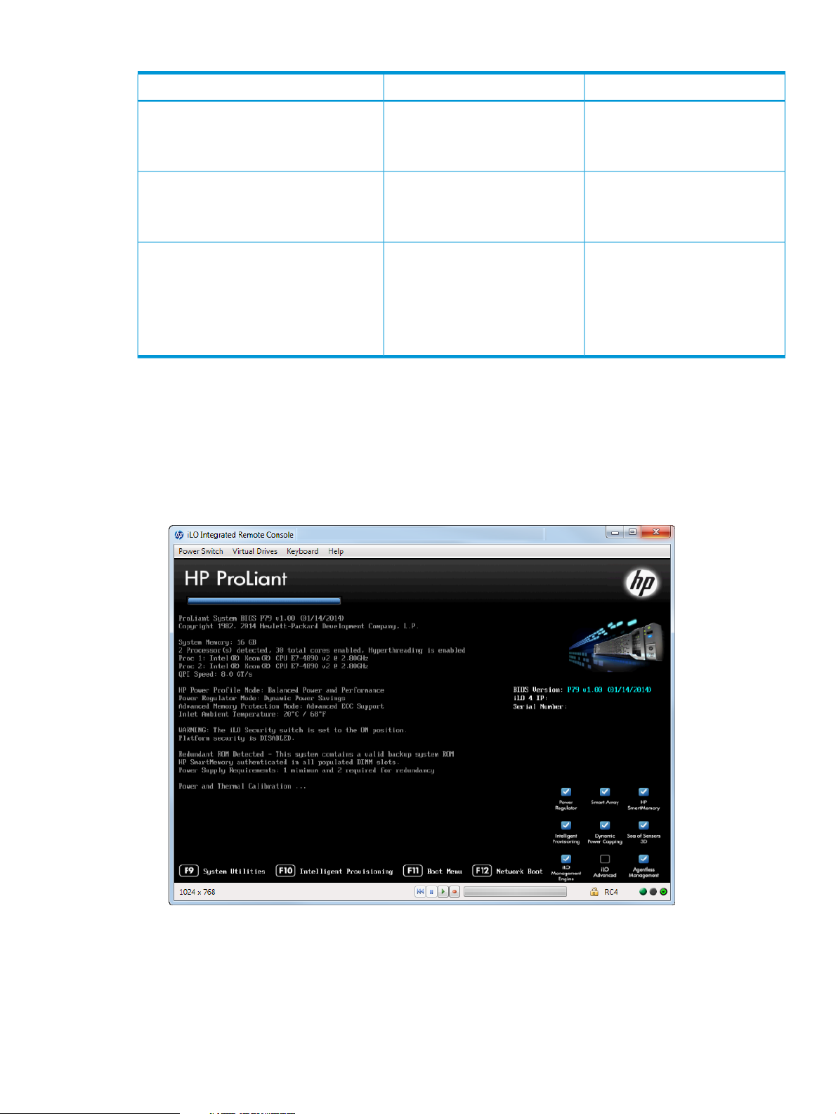
Table 3 Comparison of UEFI versus Legacy BIOS (continued)
Legacy BIOSUEFICharacteristic
The ACPI spec is maintained by the
UEFI forum, ensuring that
UEFI-compliant systems are
ACPI-compliant.
Video support
Storage support
Pre-boot video functions available
using Graphics Output Protocol
(GOP). Video renders in full
graphics mode.
Specified as a file/path name on a
storage device. Multiple boot loader
Device Selection service. one boot loader per device is
Accessing the HP UEFI System Utilities
To access the HP UEFI System Utilities:
1. Reboot the server. The server starts up and the HP ProLiant POST screen appears within a few
minutes.
2. Press F9 in the HP ProLiant POST screen. The System Utilities screen appears.
Figure 1 HP ProLiant POST screen
Legacy BIOS-based systems is an
OEM responsibility.
Pre-boot video displays in text mode
only. Requires INT10h and video
BIOS after boot.
Specified in x86 real mode code
located in the boot partition of
master boot record (MBR). BIOSfiles can co-exist on a
service INT 19h initiates thesector/device, letting you specify
bootstrap loader sequence. Onlywhich loader through the Boot
allowed.
Accessing the HP UEFI System Utilities 9
Page 10

3. To navigate through and modify settings in the menu-driven interface, use the keys defined in
the following table.
ActionKey
Press to change a selection.Up or down arrow
Press to select an entry.Enter
Press to go back to the previous screen.ESC
Press to view online help about a selected option.F1
F7
POST screen keys
F9
4. To exit the System Utilities screen and restart the server, press Esc until the main menu is
displayed. Exit the utility by selecting Exit and Resume Boot in the main menu.
Rebooting the Server
To reboot the server:
1. From a server running the iLO Remote Console screen, at the top of the menu bar in the System
Utilities screen, select Power Switch.
2. Select Cold Boot to reboot the server.
The screen displays the booting process and the HP ProLiant screen appears where the System
Utilities screen can be accessed by pressing F9.
Towards the end of the boot process, the boot options screen is displayed. This screen is
visible for several seconds before the system attempts to boot from a supported boot device.
During this time, the System Utilities can be accessed by pressing F9.
Press to load default RBSU configuration settings. You need to reboot
the system for changes to take effect. Press Enter to apply defaults.
Press ESC if you want to cancel.
Press to save your changes.F10
Press during server POST or system reboot to display the System
Utilities screen in the iLO 4 Remote Console.
Press during server POST to boot to the One-Time Boot Menu screen.F11
3. From a server not running the iLO Remote Console, press the power button to shutdown the
10 Introduction
server. Press it again to reboot the server.
Page 11
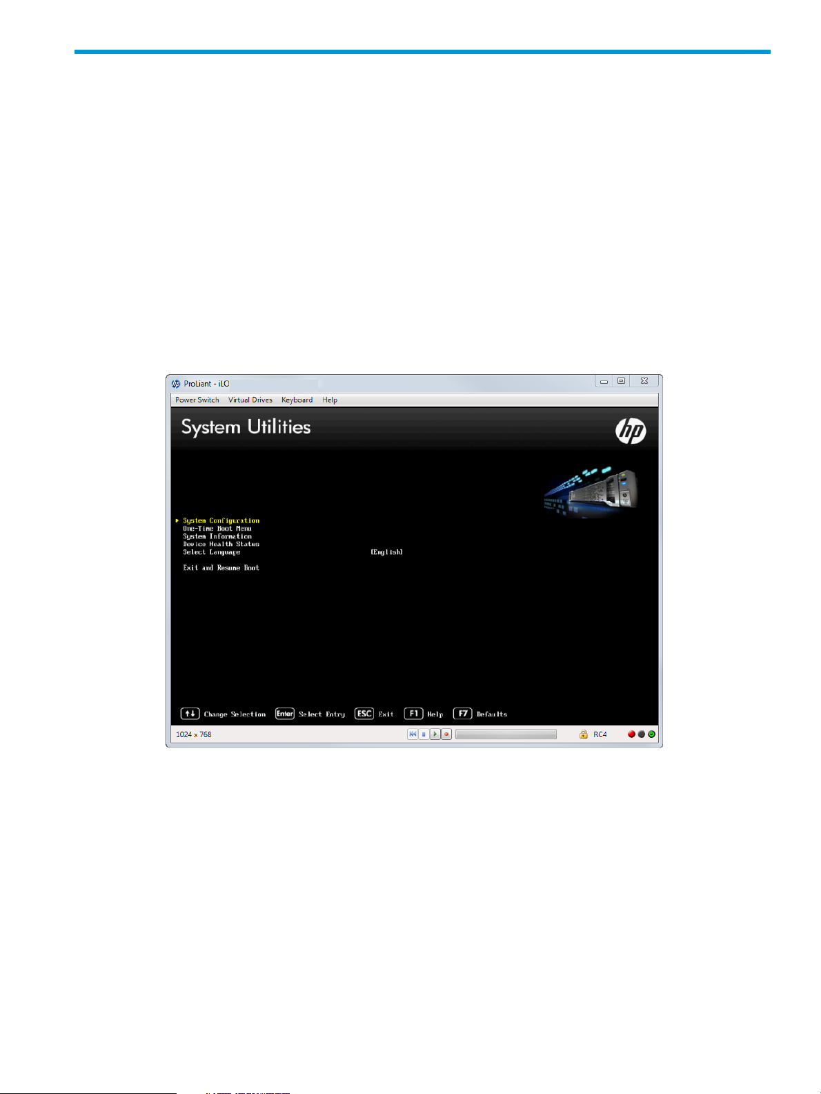
2 Getting Started: Overview of the System Utilities
Figure 2 (page 11) shows the System Utilities screen, the main screen in the UEFI System Utilities
menu-driven interface.
The following functions can be accessed from the System Utiities screen:
• System configuration
• One-Time Boot menu
• System information
• Other submenu options
To access System Utilities menu:
1. Reboot the server and press F9 when prompted during the startup sequence.
The System Utilities screen appears (English is shown as the language for the system).
Figure 2 System Utilities screen
11
Page 12

2. Use the keyboard up or down arrows to select an option, and then press Enter to display the
submenu for that option.
NOTE: You might also see options for your system devices, such as an embedded NIC. For
example, “Embedded FlexibleLOM Port 1.” These items reflect installed PCIe cards. These
devices vary based on the particular system. Configure the parameters for these devices as
needed.
You can access the following options from this screen:
System Configuration Displays the System Configuration menu, which includes
options for accessing and configuring:
• BIOS/Platform Configuration (RBSU)
NOTE: This functionality is similar to the HP ROM
Based Setup Utility, available in previous releases.
• iLO 4 Configuration Utility
A list of other devices might appear, such as NICs and Smart
Arrays. Configure these devices as needed. For more
information, see “Accessing the System Configuration Menu”
(page 13).
One-Time Boot Menu Lets you select a UEFI boot option for a one-time boot
override. Select one of the following boot override options:
• Embedded UEFI Shell
• Intelligent Provisioning
• Run a UEFI Application from a file system
• Legacy BIOS One-Time Boot Menu
For more information, see “Configuring a One-Time Boot
Menu” (page 139).
System Information Displays the server name and generation, serial number,
product ID, BIOS version and date, power management
controller, backup BIOS version and date, system memory,
and processors.
For more information, see “Viewing System Information”
(page 143).
Device Health Status Displays the current health status of the server.
For more information, see “Viewing Device Health Status”
(page 144).
Select Language Set the language to use in the user interface
For more information, see “Selecting a Language” (page 145).
Exit and Resume Boot Continues to go through boot order list and launches the first
bootable option in the system. For example, you can launch
the UEFI Shell, if enabled and registered as first bootable
option in the boot order list.
For more information, see “Exiting and Resuming Boot”
(page 146).
12 Getting Started: Overview of the System Utilities
Page 13
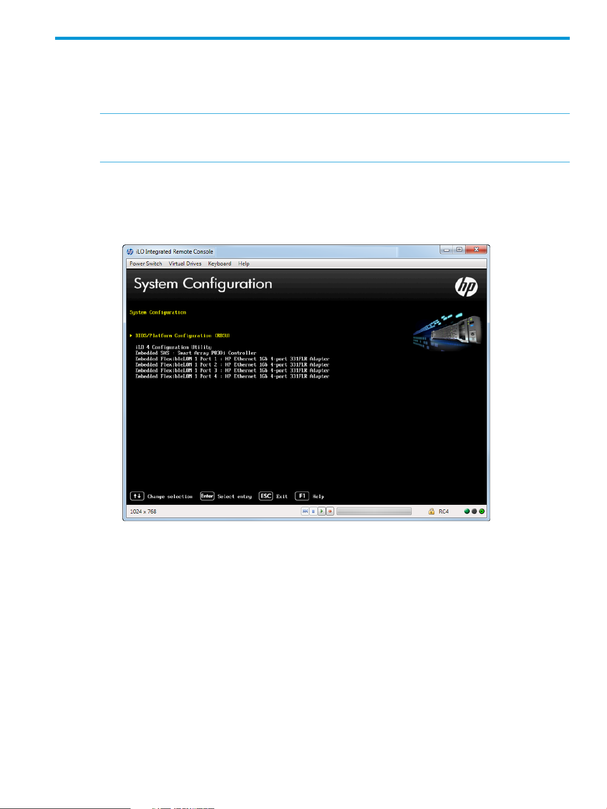
3 Accessing the System Configuration Menu
The System Configuration menu options control a wide variety of server configurations.
Figure 3 (page 13) shows the System Configuration portion of the UEFI System Utilities.
NOTE: You might also see options for your system devices such as embedded NIC. For example,
“Embedded FlexibleLOM Port 1.” These devices vary based on the particular system. Configure
the parameters for these devices as needed by selecting the device and pressing Enter.
To access the System Configuration menu:
1. From the System Utilities screen, select System Configuration and press Enter.
The System Configuration screen appears.
Figure 3 System Configuration screen
2. Select an option and then press Enter. Options are:
• “Accessing the BIOS/Platform Configuration (RBSU) menu” (page 13)
• “Accessing Smart Array Controllers” (page 121)
• “Using the iLO 4 Configuration Utility” (page 123)
Accessing the BIOS/Platform Configuration (RBSU) menu
The BIOS/Platform Configuration, formerly known as ROM-Based Setup Utility (RBSU), is embedded
in the system ROM of the HP ProLiant DL580 Gen8 servers. This menu lets you configure system
BIOS configuration settings.
Figure 4 (page 14) shows the BIOS/Platform Configuration (RBSU) portion of the UEFI System
Utilities.
To access the BIOS/Platform Configuration menu:
Accessing the BIOS/Platform Configuration (RBSU) menu 13
Page 14
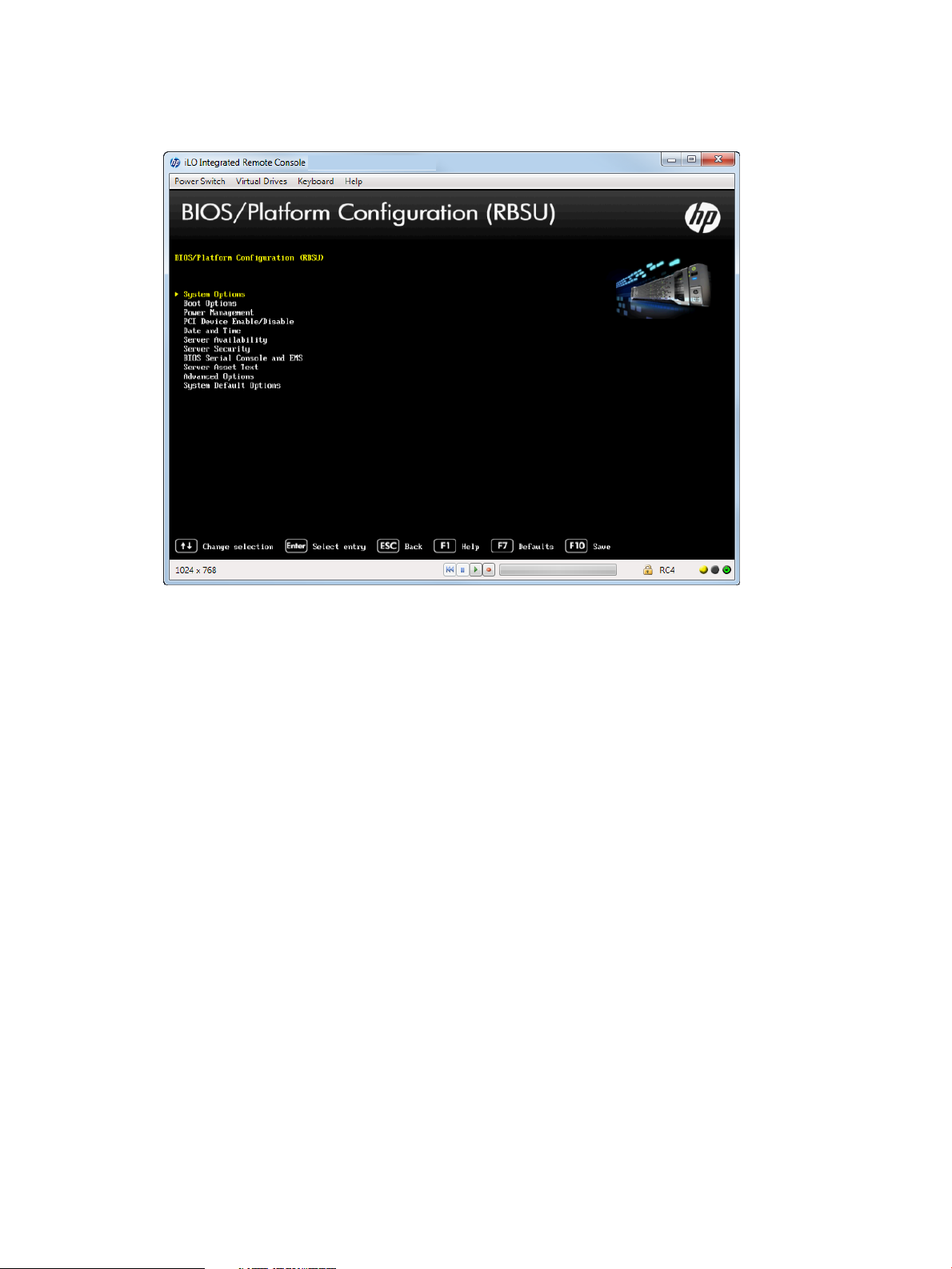
1. From the System Utilities screen, select System Configuration→BIOS/Platform Configuration.
The BIOS/Platform Configuration (RBSU) screen appears.
Figure 4 BIOS/Platform Configuration screen
2. Select an option, and then press Enter. Options are:
• “Accessing the System Options menu” (page 14)
• “Accessing Boot Options” (page 34)
• “Accessing Power Management” (page 44)
• “Setting Embedded and Add-in Devices” (page 55)
• “Setting the System Date and Time” (page 56)
• “Accessing the Server Availability menu” (page 57)
• “Accessing the Server Security menu” (page 65)
• “Accessing the BIOS Serial Console and EMS Console” (page 78)
• “Accessing the Server Asset Text menu” (page 83)
• “Accessing Advanced Options” (page 88)
• “Accessing System Default Options” (page 116)
Accessing the System Options menu
Figure 5 (page 15) shows the System Options screen.
System settings can be configured from the System Options menu, such as:
• Serial port options
• USB port options
• Processor options
• Network boot options
To access the System Options menu:
14 Accessing the System Configuration Menu
Page 15
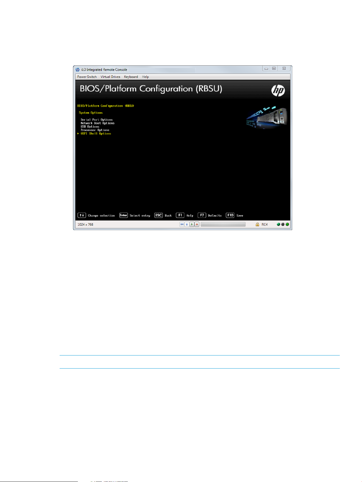
1. From the System Utilities screen, select System Configuration→BIOS/Platform
Configuration→System Options.
The System Options screen appears.
Figure 5 System Options screen
2. Select one of the following options and press Enter.
• Serial Port Options—Assigns COM port number and associated resources to the selected
physical serial port. Also, lets you assign the logical COM port address and associated
default resources for the Virtual Serial Port (VSP).
• Network Boot Options—Configures network boot policies, such as enabling or disabling
a network boot for embedded NICs.
• USB Options—Configures USB ports.
• Processor Options—Configures processors.
• UEFI Shell Options—Configures UEFI shell options.
Accessing Serial Port Options
This menu lets you configure the Embedded and Virtual Serial Port settings.
NOTE: For proper screen resolution, set the console resolution in the terminal software to 100x31.
To access serial port options:
• From the System Utilities screen, select System Configuration→BIOS/Platform Configuration
(RBSU)→System Options→Serial Port Options.
The Serial Port Options screen appears.
Options include:
• “Setting the Embedded Serial Port” (page 16)
• “Setting the Virtual Serial Port” (page 16)
Accessing the BIOS/Platform Configuration (RBSU) menu 15
Page 16
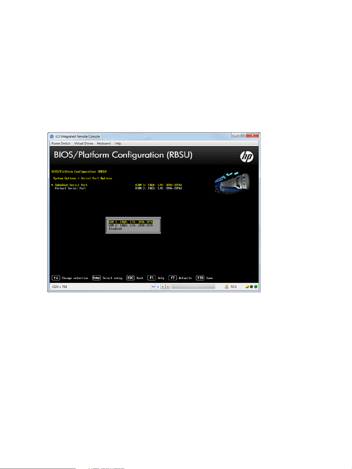
Setting the Embedded Serial Port
You can assign a logical COM port address and associated default resources to the selected
physical serial port. The operating system can overwrite this setting.
1. From the System Utilities screen, select System Configuration→BIOS/Platform Configuration
(RBSU)→System Options→Serial Port Options→Embedded Serial Port and press Enter.
2. Select one of the following options:
• COM 1: IRQ4: I/0: 3F8h-3FFh (default)
• COM2: IRQ3: I/0: 2F8h-2FFh
• Disabled
3. Press F10 to accept your selection.
Figure 6 Serial Port Options — Embedded Serial Port screen
Setting the Virtual Serial Port
You can assign a logical COM port address and associated default resources used by the Virtual
Serial Port (VSP). VSP lets the iLO Management Controller appear as a physical serial port to
support the BIOS Serial Console and the operating system serial console.
1. From the System Utilities screen, select System Configuration→BIOS/Platform Configuration
(RBSU)→System Options→Serial Port Options→Virtual Serial Port and press Enter.
2. Select one of the following options:
• COM 1: IRQ4: I/0: 3F8h-3FFh
• COM2: IRQ3: I/0: 2F8h-2FFh (default)
• Disabled
3. Press F10 to save your selection.
16 Accessing the System Configuration Menu
Page 17
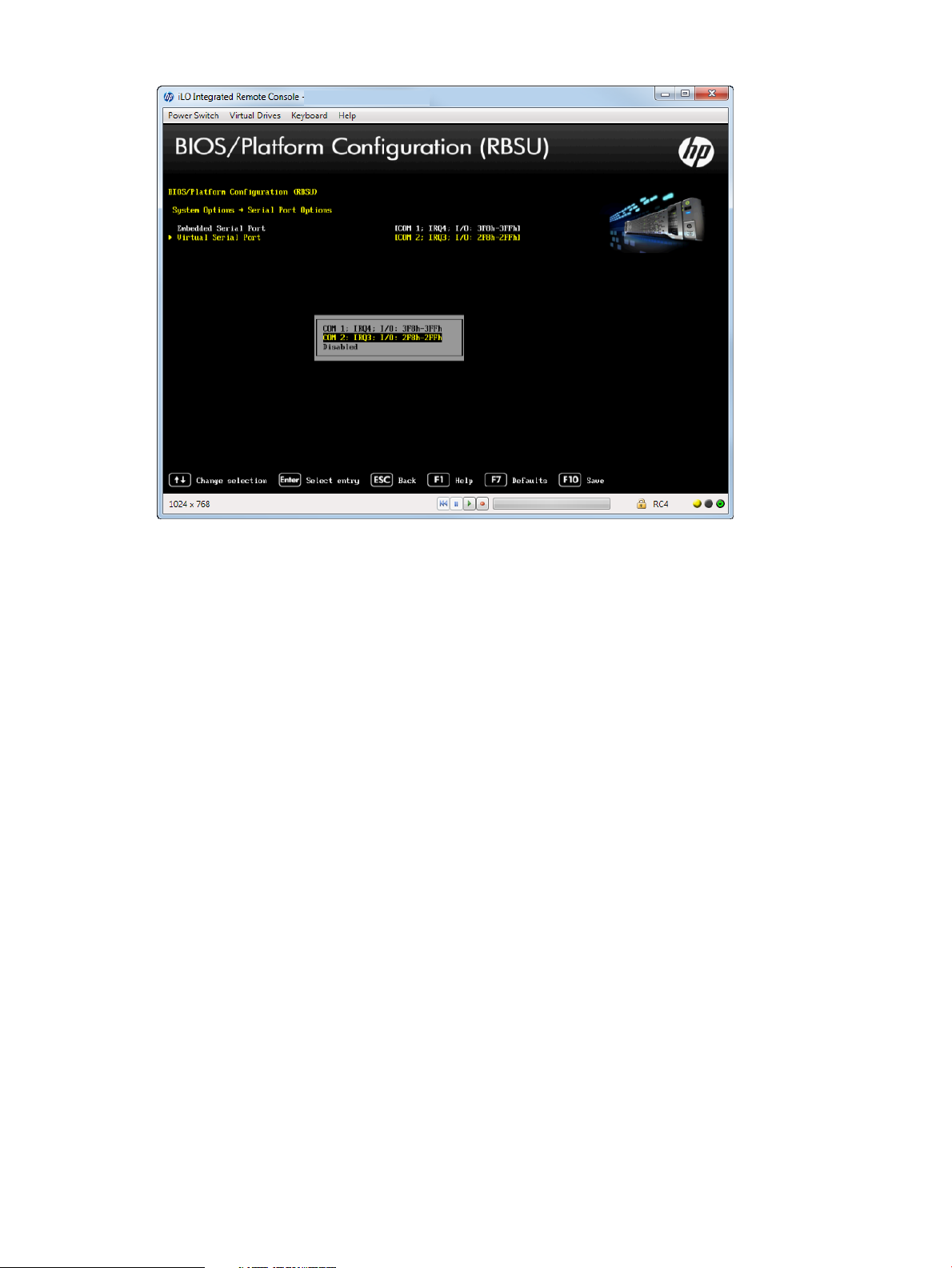
Figure 7 Serial Port Options — Virtual Serial Port screen
Accessing Network Boot Options
You can configure network boot settings, such as enabling or disabling network boot for Embedded
NICs or setting the PXE boot policy.
To access Network Boot Options:
1. From the System Utilities screen, select System Configuration→BIOS/Platform Configuration
(RBSU)→System Options→Network Boot Options.
Accessing the BIOS/Platform Configuration (RBSU) menu 17
Page 18
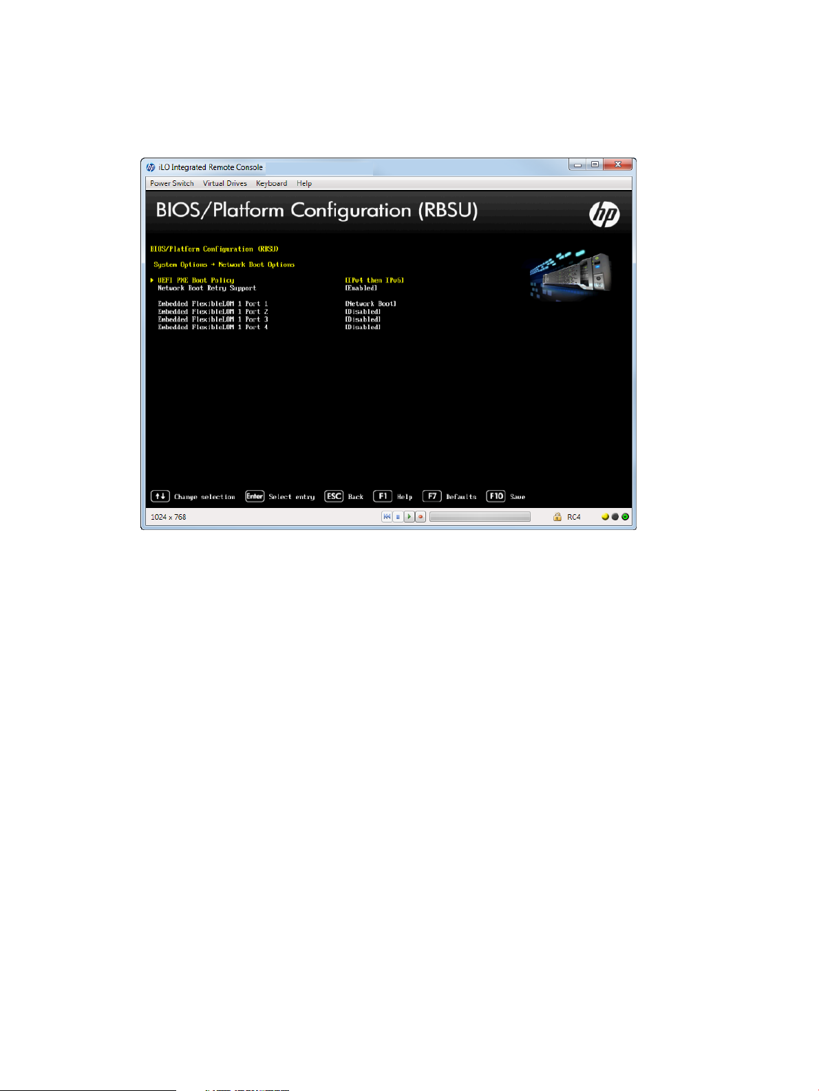
2. Select one of the following options:
• “Selecting a UEFI PXE Boot Policy” (page 18)
• “Setting Network Boot Retry Support” (page 19)
Figure 8 Network Boot Options screen
Selecting a UEFI PXE Boot Policy
You can select the UEFI PXE (Pre-Boot Execution Environment) network boot policy. If both IPv4 and
IPv6 are enabled, each network boot target appears twice in the UEFI boot order list (one for IPv4
and the other for IPv6). You can only configure this option when Boot Mode is set to UEFI. For
more information, see “Selecting a Boot Mode” (page 41).
To select a UEFI PXE boot order:
1. From the System Utilities screen, select System Configuration→BIOS/Platform Configuration
(RBSU)→System Options→Network Boot Options→UEFI PXE Boot Policy and press Enter.
2. Select one of the following options:
• IPv4 then IPv6
• IPv4
• IPv6
• IPv6 then IPv4
• Auto (default)
3. Press F10 to save your selection.
18 Accessing the System Configuration Menu
Page 19
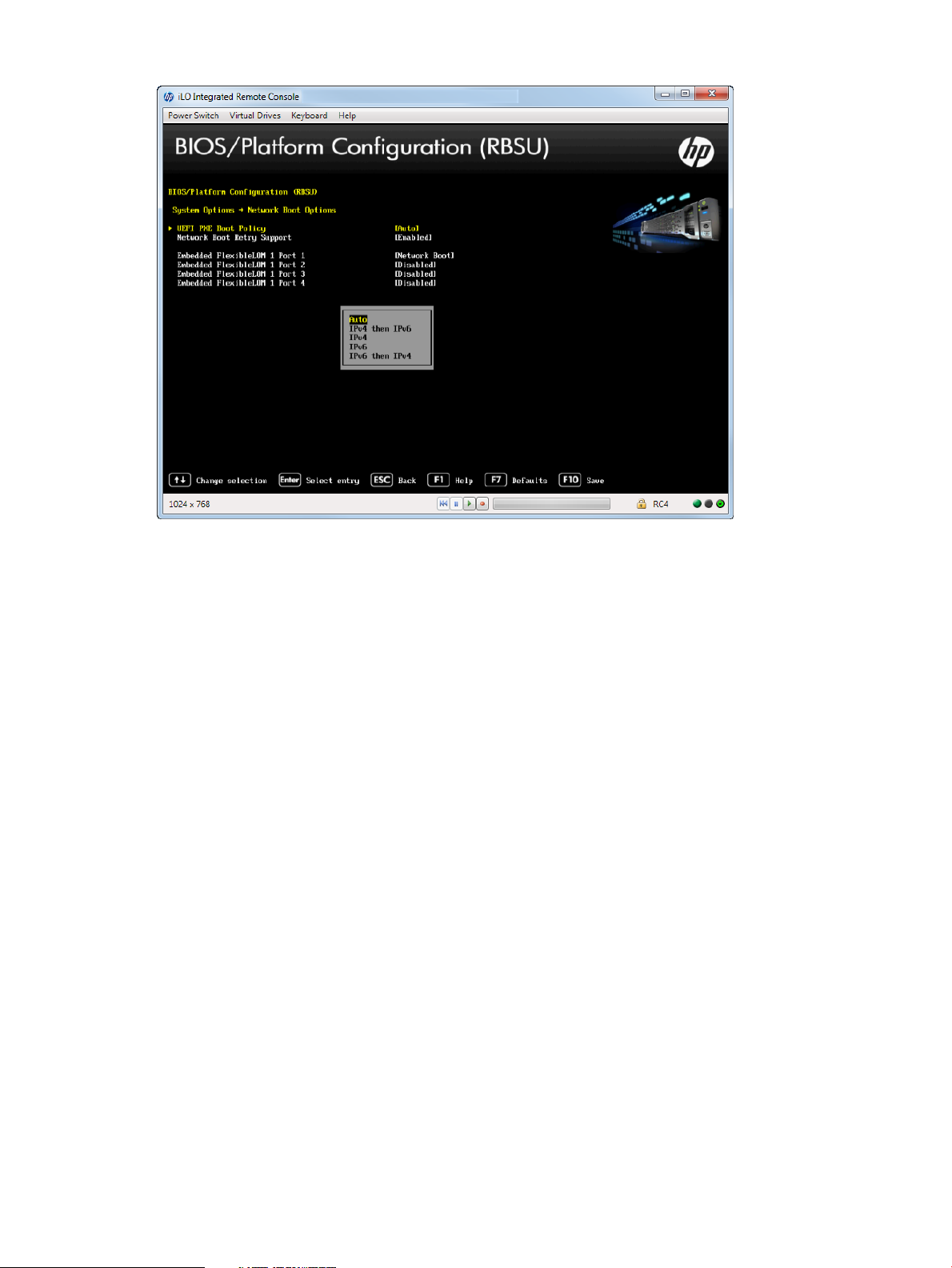
Figure 9 Network Boot Options —UEFI PXE Boot Policy screen
Setting Network Boot Retry Support
You can set the network boot retry setting. By default, the system BIOS attempts to boot the network
device (for example, PXE device) up to 20 times before attempting to boot the next IPL device.
To set Network Boot Retry support:
1. From the System Utilities screen, select System Configuration→BIOS/Platform Configuration
(RBSU)→System Options→Network Boot Options →Network Boot Retry Support and press
Enter.
2. Select one of the following options:
• Enabled (default)
• Disabled
3. Press F10 to accept your selection.
Accessing the BIOS/Platform Configuration (RBSU) menu 19
Page 20
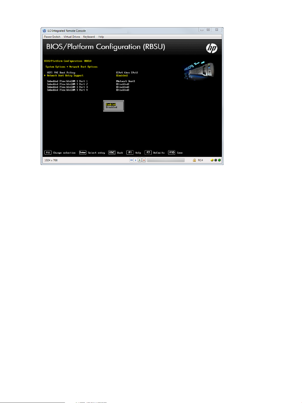
Figure 10 Network Boot Options — Network Boot Retry Support screen
Accessing USB Options
This menu lets you set USB control, USB boot support, and removable flash media boot sequence.
To access USB options:
1. From the System Utilities screen, select System Configuration→BIOS/Platform Configuration
(RBSU)→System Options→USB Options.
2. Select the following options:
• “Setting USB Control” (page 20)
• “Setting USB Boot Support” (page 21)
• “Setting Removable Flash Media Boot Sequence” (page 22)
Setting USB Control
Use the USB Control option to configure how USB ports and embedded devices operate at startup.
To set USB controls:
1. From the System Utilities screen, select System Configuration→BIOS/Platform Configuration
(RBSU)→System Options→USB Options→USB Control and press Enter.
2. Select one of the following options:
• USB Enabled (default)—Enables all USB ports and embedded devices.
• External USB Port Disabled—Only external USB ports are disabled; however, embedded
USB devices have full support under the ROM and operating system.
3. Press F10 to save your selection.
20 Accessing the System Configuration Menu
Page 21
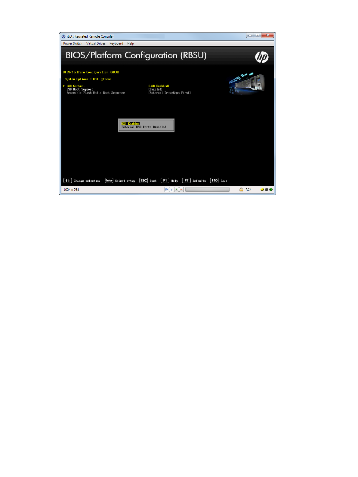
Figure 11 Network Boot Options —USB Control screen
Setting USB Boot Support
Use this option to prevent the system from booting any USB devices connected to the server and
to disable booting the iLO virtual media.
To set USB boot support:
1. From the System Utilities screen, select System Configuration→BIOS/Platform Configuration
(RBSU)→System Options→USB Options→USB Boot Support and press Enter.
2. Select one of the following options:
• Enabled (default)
• Disabled
3. Press F10 to save your selection.
Accessing the BIOS/Platform Configuration (RBSU) menu 21
Page 22

Figure 12 USB Options — USB Boot Support screen
Setting Removable Flash Media Boot Sequence
Select which USB or SD Card devices you want to search first when enumerating boot devices.
Select whether the system should attempt to boot external USB drive keys, internal USB drive keys,
or the internal SD Card slot first. This option does not override the device boot order in the Standard
Boot Order (IPL) option. Configure this option only when Boot Mode is set to Legacy BIOS. See
“Selecting a Boot Mode” (page 41) for more information.
To select removable flash media boot sequence:
1. From the System Utilities screen, select System Configuration→BIOS/Platform Configuration
(RBSU)→System Options→USB Options→Removable Flash Media Boot Sequence and press
Enter.
2. Select one of the following options:
• Internal SD Card First—Boot using the internal SD card slot.
• Internal Drive Keys First—Boot using the internal USB drive keys.
• External Drive Keys First (default)—Boot using external USB drive keys.
3. Press F10 to save your selection.
22 Accessing the System Configuration Menu
Page 23
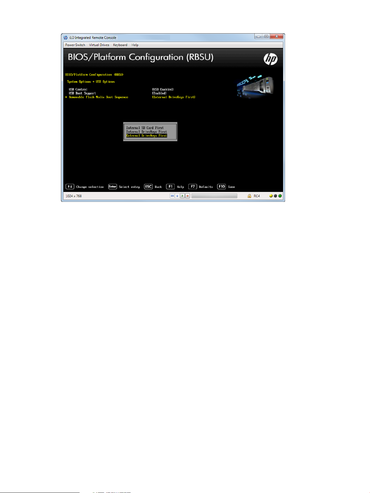
Figure 13 Options — Removable Flash Media Boot Sequence screen
Configuring Processor Options
You can configure processor options, such as protecting a system from viruses, enabling
virtualization technology, disabling Intel Hyperthreading, enabling processor cores, and enabling
Intel Virtualization Technology.
To access processor options:
• From the System Utilities screen, select System Configuration→BIOS/Platform Configuration
(RBSU)→System Options→Processor Options.
Depending on your server model, options can include:
• “Protecting a System from Viruses” (page 23)
• “Enabling Virtualization Technology” (page 24)
• “Disabling Intel Hyper-Threading” (page 25)
• “Disabling Processor Cores” (page 26)
• “Setting Intel Turbo Boost Technology” (page 27)
• “Enabling Intel VT-d” (page 28)
Protecting a System from Viruses
You can protect as system against malicious code and viruses. Memory is marked as non-executable
unless the location contains executable code. Some viruses attempt to insert and execute code
from non-executable memory locations; these are intercepted and an exception is generated. Your
operating system needs to support this option.
To protect a system from viruses:
1. From the System Utilities screen, select System Configuration→BIOS/Platform Configuration
(RBSU)→System Options→Processor Options→No-Execute Protection and press Enter.
2. Select one of the following options:
• Enabled (default)
• Disabled
Accessing the BIOS/Platform Configuration (RBSU) menu 23
Page 24
3. Press F10 to save your selection.
NOTE: Ensure this option is enabled if using Virtual Machine Manager, such as VMware ESX/ESXi
and Windows Hyper-V.
Figure 14 Processor Options — No-Execute Protection screen
Enabling Virtualization Technology
You can configure a Virtual Machine Manager that supports this option to use hardware capabilities
provided by Intel’s virtualization technology.
To enable virtualization technology:
1. From the System Utilities screen, select System Configuration→BIOS/Platform Configuration
(RBSU)→System Options→Processor Options→Virtualization Technology and press Enter.
2. Select one of the following options:
• Enabled (default)—When enabled, a Virtual Machine Manager (VMM) supporting this
option can use hardware capabilities provided by UEFI Intel processors.
• Disabled —It is not required to disable this option if using a VMM or an OS that does
not support AMD V.
3. Press F10 to save your selection.
24 Accessing the System Configuration Menu
Page 25

Figure 15 Processor Options — Virtualization Technology screen
Disabling Intel Hyper-Threading
You can disable the logical processor cores on processors supporting Intel’s Hyper-Threading
Technology. This option improves overall performance for applications that benefit from a higher
processor core count. The option is supported through the system BIOS.
NOTE: Hyper-Threading is not supported on all processors. For more information, see the
documentation for your processor model.
To disable Intel Hyper-Threading:
1. From the System Utilities screen, select System Configuration→BIOS/Platform Configuration
(RBSU)→System Options→Processor Options→Intel Hyperthreading Options and press Enter.
2. Select one of the following options:
• Enabled (default)—Enables the logical processor cores on processors supporting Intel
Hyper-Threading technology.
• Disabled—Disables the logical processor cores on processors supporting Intel
Hyper-Threading technology.
3. Press F10 to save your selection.
Accessing the BIOS/Platform Configuration (RBSU) menu 25
Page 26
Figure 16 Processor Options — Intel Hyper-Threading Options screen
Disabling Processor Cores
You can disable processor cores that use Intel Core Multi-Processing (CMP) Technology. This option
can reduce processor power usage and improve performance with some applications. It can
improve overall performance for applications that benefit from higher performance cores rather
than more processing cores. This option can also address issues with software that is licensed on
a per-core basis. The value enter should be the number of enabled cores per socket.
To disable processor cores:
1. From the System Utilities screen, select System Configuration→BIOS/Platform Configuration
(RBSU)→System Options→Processor Options→Processor Core Disable and press Enter.
2. Press any key to display the message box, which lets you enter the number of cores to enable
per processor socket. Entering an incorrect value results in no cores being disabled. 0 = Enable
All Cores.
3. Press F10 to save your selection.
26 Accessing the System Configuration Menu
Page 27
Figure 17 Processor Options — Processor Core Disable screen
Setting Intel Turbo Boost Technology
Turbo Boost Technology lets the processor transition to a higher frequency than the processor's
rated speed if the processor has available power and is within temperature specifications.
To set Intel Turbo Boost technology:
1. From the System Utilities screen, select System Configuration→BIOS/Platform Configuration
(RBSU)→System Options→Processor Options→Intel Hyperthreading Options and press Enter.
2. Select one of the following options:
• Enabled (default)—Enables the logical processor cores on processor supporting
hyperthreading technology.
• Disabled—Disabling this option reduces power usage and also reduces the system’s
maximum achievable performance under some workloads.
3. Press F10 to save your selection.
Accessing the BIOS/Platform Configuration (RBSU) menu 27
Page 28
Figure 18 Intel Turbo Boost Technology screen
Enabling Intel VT-d
You can enable a Virtual Machine Manager (VM Manager must support this feature) to use
hardware capabilities provided by the Intel Virtualization Technology for Directed I/O.
To enable Intel VT-d:
1. From the System Utilities screen, select System Configuration→BIOS/Platform Configuration
(RBSU)→System Options→Processor Options→Intel VT-d and press Enter.
2. Select one of the following options:
• Enabled (default)
• Disabled
3. Press F10 to save your selection.
28 Accessing the System Configuration Menu
Page 29

Figure 19 Processor Options — Intel VT-d screen
Accessing UEFI Shell Options
You can enable the UEFI Shell, add the Embedded UEFI Shell in the boot order, and enable
automatic execution of the default startup script for the Embedded UEFI Shell.
To access UEFI Shell options:
1. From the System Utilities screen, select System Configuration→BIOS/Platform Configuration
(RBSU)→System Options→UEFI Shell Options.
2. Select any of the following options:
• “Enabling the Embedded UEFI Shell” (page 30)
• “Adding Embedded UEFI Shell to the boot order list” (page 31)
• “Enabling the UEFI Shell Script Auto Start” (page 32)
Accessing the BIOS/Platform Configuration (RBSU) menu 29
Page 30
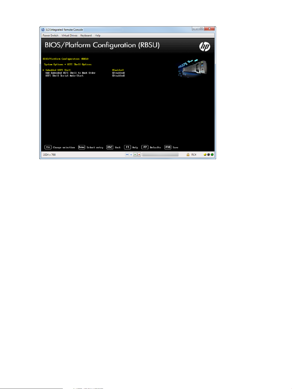
Figure 20 UEFI Shell Options screen
Enabling the Embedded UEFI Shell
You can enable or disable the Embedded UEFI Shell. The UEFI Shell is a pre-boot command line
environment for scripting and running UEFI applications, including UEFI boot loaders. The UEFI
Shell also provides CLI-based commands to obtain system information and configure and update
the system BIOS. Enabling this option adds the Embedded UEFI Shell to the UEFI boot options. You
can only configure this option if Boot Mode is set to UEFI. See “Selecting a Boot Mode” (page 41)
for more information.
To set the Embedded UEFI Shell:
1. From the System Utilities screen, select System Configuration→BIOS/Platform Configuration
(RBSU)→System Options→UEFI Shell Options→Embedded UEFI Shell and press Enter.
2. Select one of the following options:
• Enabled (default)
• Disabled
3. Press F10 to save your selection.
4. See the HP UEFI Shell User Guide details on running Shell scripts.
30 Accessing the System Configuration Menu
Page 31

Figure 21 UEFI Shell Options — Embedded UEFI Shell screen
Adding Embedded UEFI Shell to the boot order list
Adding the Embedded UEFI Shell as an entry in the Boot Order list is only applicable when the
Embedded UEFI Shell is enabled and Boot Mode is set as UEFI. Otherwise, this option is grayed
out.
NOTE: When enabling this option, the Embedded UEFI Shell does not appear in the UEFI Boot
Order list until the next system reboot.
To add the Embedded UEFI Shell to the boot order list:
1. From the System Utilities screen, select System Configuration→BIOS/Platform Configuration
(RBSU)→System Options→UEFI Shell Options→Add Embedded UEFI Shell to Boot Order and
press Enter.
2. Select one of the following options:
• Enabled (default)—Adds the embedded UEFI Shell to the boot order.
• Disabled
3. Press F10 to save your selection.
Accessing the BIOS/Platform Configuration (RBSU) menu 31
Page 32

Figure 22 UEFI Shell Options — Add Embedded UEFI Shell to the Boot Order screen
Enabling the UEFI Shell Script Auto Start
You can enable or disable automatic execution of the default UEFI Shell startup script during shell
startup. When enabled, the shell looks for the startup.nsh file in any of the FAT16 or FAT32
file systems available. If you do not have the startup.nsh file, name the script file “startup.nsh”
and place it in a UEFI accessible file system on a fixed or removable media. Configure this option
only when Boot Mode is set to UEFI. HP recommends that you have only one startup.nsh file
on one file system. See “Selecting a Boot Mode” (page 41) for more information.
To enable the UEFI Shell script auto start:
1. From the System Utilities screen, select System Configuration→BIOS/Platform Configuration
(RBSU)→System Options→UEFI Shell Options→UEFI Shell Script Auto-Start and press Enter.
2. Select Enabled and press Enter to enable the UEFI Shell Script Auto Start.
3. Press F10 to save your selection.
4. Reboot the server for the change to take effect.
32 Accessing the System Configuration Menu
Page 33

Figure 23 Shell Options — UEFI Shell Script Auto Start screen
Configuring Advanced Memory Protection
You can configure additional memory protection with ECC (error checking and correcting).
Advanced ECC provides the largest memory capacity to the operating system.
To configure advanced memory protection:
1. From the System Utilities screen, select System Configuration→BIOS/Platform Configuration
(RBSU)→System Options→Advanced Memory Protection and press Enter.
2. Select one of the following options:
• Advanced ECC Support (default) — Configures the largest memory capacity to the operation
system while protecting the system against all single-bit failures and some multi-bit failures.
This option provides up to 4–bit error correction and enhanced performance over Lockstep
mode.
• Online Spare with Advanced ECC Support — Configures a system to automatically map
out a group of memory that is receiving excessive correctable memory errors. This memory
is replaced by a spare group of memory.
• Mirrored Memory with Advanced ECC Support — Configures maximum protection against
uncorrectable memory errors that can otherwise result in a system failure.
• Lockstep Mode with Advanced DDDC Support — Configures maximum data protection
by correcting multiple-bit memory errors (using Double Data Device Correction (DDDC)
support) that Advanced ECC mode cannot detect. Lockstep mode improves system
reliability and availability.
Accessing the BIOS/Platform Configuration (RBSU) menu 33
Page 34

Figure 24 Advanced Memory Protection screen
Accessing Boot Options
You can change the order of the UEFI boot order list, change the order of Legacy boot settings,
select a boot mode, and set the UEFI optimized boot mode.
NOTE: The server needs to be rebooted when changes are made to the boot mode
To access the boot options:
1. From the System Utilities screen, select System Configuration→BIOS/Platform Configuration
(RBSU)→Boot Options and press Enter.
2. Select an option, and then press Enter. Options are as follows:
• “Changing the UEFI boot order list” (page 35)
• “Accessing Advanced UEFI Boot Maintenance options” (page 36)
• “Setting the Legacy Boot Mode order” (page 40)
• “Selecting a Boot Mode” (page 41)
• “Setting the Boot Order Policy” (page 43)
• “Setting UEFI Optimized Boot” (page 42)
34 Accessing the System Configuration Menu
Page 35

Figure 25 Boot Options screen
Changing the UEFI boot order list
To change the order of the UEFI boot list:
1. From the System Utilities screen, select System Configuration→BIOS/Platform Configuration
(RBSU)→Boot Options→UEFI Boot Order and press Enter. The UEFI Boot Order screen appears.
2. Select Enter to open the Boot Order list.
3. Use the arrow keys to navigate within the boot order list.
4. Press the + key (plus) to move an entry higher in the boot list.
5. Press the - key (minus) to move an entry lower in the list.
6. Press F10 to save your selection.
7. From the System Utilities screen, select Exit and Resume Boot.
8. Reboot the server for the change to take effect.
Accessing the BIOS/Platform Configuration (RBSU) menu 35
Page 36

Figure 26 Boot Options — UEFI Boot Order screen
Accessing Advanced UEFI Boot Maintenance options
Advanced UEFI boot maintenance options let you add an OS boot loader or application file that
is located on removable media either attached to the server or virtual media from the iLO console.
To access advanced UEFI boot maintenance options:
1. From the System Utilities screen, select System Configuration→Advanced UEFI Boot Maintenance
and press Enter.
2. Select one of the following options:
• “Adding a Boot Option” (page 37)
• “Deleting a Boot Option” (page 39)
36 Accessing the System Configuration Menu
Page 37

Figure 27 Advanced Boot Maintenance screen
Adding a Boot Option
You can browse all FAT16 and FAT32 file systems. You can then select an X64 UEFI application
with an .EFI extension to add as a new UEFI boot option (such as an OS boot loader or other UEFI
application). The new boot option is appended to the boot order list. Once you select a file, you
are prompted to enter the boot option description (which is then displayed in the Boot menu), as
well as any optional data to be passed to an .EFI application.
To add boot options:
1. Attach media with a FAT16 or FAT32 partition on it.
2. From the System Utilities screen, select System Configuration→Advanced Boot
Maintenance→Add Boot Option and press Enter.
3. Browse for a .EFI application from the list and press Enter as shown in Figure 28 (page 38).
4. Press Enter to drill-down if necessary.
5. Input the boot option description and optional data as shown in Figure 29 (page 38). A new
boot option appears in the UEFI boot order. For example as shown in Figure 30 (page 39).
6. Select Commit changes and exit to save your selection.
Accessing the BIOS/Platform Configuration (RBSU) menu 37
Page 38

Figure 28 Add Boot Option screen
Figure 29 Modify Boot Option Description screen
38 Accessing the System Configuration Menu
Page 39
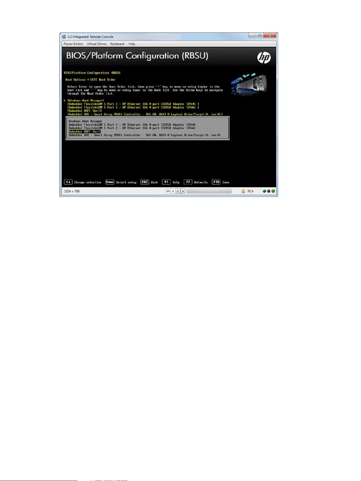
Figure 30 UEFI Boot Order — Example
Deleting a Boot Option
You can delete a UEFI boot option from the boot order list. If the options points to a standard boot
location (such as Network PXE boot or a removable media device), the system BIOS adds the
option on the next system reboot.
To delete boot options:
1. From the System Utilities screen, select System Configuration→Advanced UEFI Boot
Maintenance→Delete Boot Option and press Enter.
2. Select a port from the list.
3. Select one of the following options:
• Commit Changes and Exit
• Discard Changes and Exit
4. Select Commit Changes and Exit to save your selection.
Accessing the BIOS/Platform Configuration (RBSU) menu 39
Page 40

Figure 31 Delete Boot Option screen
Setting the Legacy Boot Mode order
If your server is configured in Legacy mode, you can change the order for Legacy Boot Mode
settings. This settings defines how the server looks for OS boot firmware.
To change Legacy boot settings:
1. From the System Utilities screen, select System Configuration→BIOS/Platform Configuration
(RBSU)→Boot Options→Legacy BIOS Boot Order and press Enter. The Legacy Boot Order
screen appears.
2. Select an option from the Standard Boot Order list and use the up and down arrow keys to
move the option to where you want it to appear in the list. Choose CD ROM/DVD, USB
DriveKey, Hard Drive C, or an embedded device.
3. Press F10 to save your selection.
4. Reboot the server for the change to take effect.
40 Accessing the System Configuration Menu
Page 41

Figure 32 Legacy Boot Order screen
Selecting a Boot Mode
You can select the boot mode for the system to be either UEFI or Legacy BIOS.
To select a boot mode:
1. From the System Utilities screen, select System Configuration→BIOS/Platform Configuration
(RBSU)→Boot Options→Boot Mode and press Enter. The Boot Mode screen appears.
2. Select one of the following options:
• UEFI Mode—Configures the system to boot to a UEFI compatible operating system.
• Legacy BIOS Mode—Configures the system to boot to a traditional operating system in
Legacy BIOS compatibility mode.
3. Press F10 to save your selection.
4. From the System Utilities screen, select Exit and Resume Boot.
5. Reboot the server for the change to take effect.
Accessing the BIOS/Platform Configuration (RBSU) menu 41
Page 42
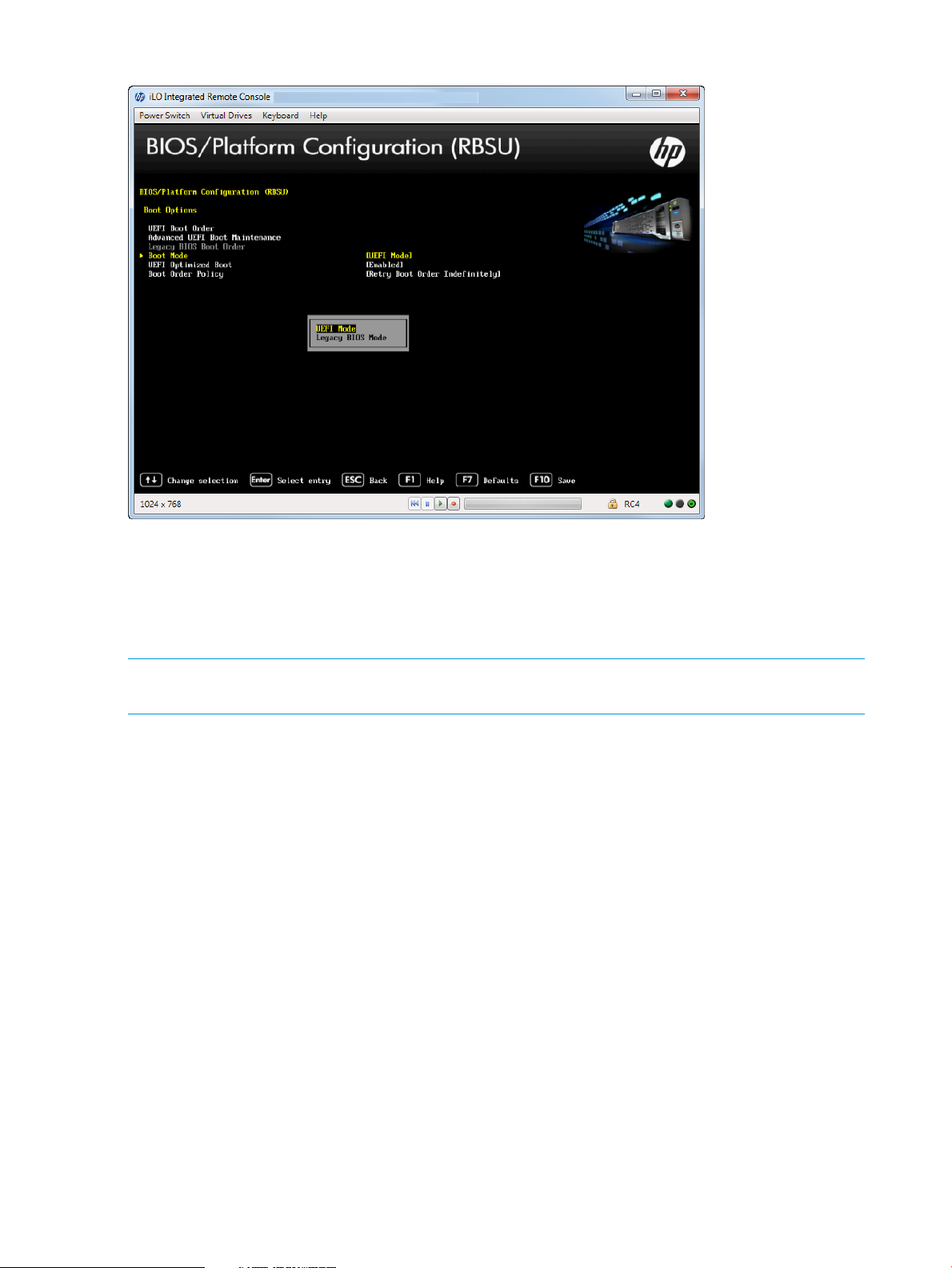
Figure 33 Boot Mode screen
Setting UEFI Optimized Boot
Configure the system to use native UEFI graphic drivers when booting to the UEFI Boot Mode. This
option needs to be enabled to configure Secure Boot. For more information, see “Configuring
Secure Boot” (page 69) for more information. Set the Boot Mode to UEFI before you can configure
this option. See “Selecting a Boot Mode” (page 41) for detailed information.
NOTE: This option must be disabled, when using Microsoft Windows 2008 R2 in UEFI Boot
Mode because Legacy BIOS components are needed for video operations in Windows.
To set the UEFI Optimized Boot:
1. From the System Utilities screen, select System Configuration→BIOS/Platform Configuration
(RBSU)→Boot Options→UEFI Optimized Boot and press Enter. The UEFI Optimized Boot screen
appears.
2. Select one of the following options:
• Enabled—Configures the system BIOS to boot using native UEFI graphic drivers.
• Disabled (default)—Configures the system BIOS to boot using INT10 legacy video
expansion ROM. This setting needs to be disabled to boot Windows Server 2008 R2 in
UEFI Boot Mode. This option cannot be disabled if Secure Boot is enabled. Configure
this option only if Boot Mode is set to UEFI. For more details, see “Selecting a Boot Mode”
(page 41).
3. Press F10 to save your selection.
4. Reboot the server for the change to take effect.
42 Accessing the System Configuration Menu
Page 43

Figure 34 UEFI Optimized Boot screen
Setting the Boot Order Policy
You can control the platform behavior when booting through the boot order.
To set the Boot Order Policy:
1. From the System Utilities screen, select System Configuration→BIOS/Platform Configuration
(RBSU)→Boot Options→Boot Order Policy and press Enter. The Boot Order Policy screen
appears.
2. Select one of the following options:
• Retry Boot Order Indefinitely (default)—Configures the system to continuously attempt the
boot order until a bootable device is found.
• Attempt Boot Order Once—Configures the system to attempt to execute all items in the
boot menu once and then halts.
• Reset After Failed Boot Attempt—Configures the system to attempt to execute all items
once and then the system is rebooted.
3. Press F10 to save your selection.
4. Reboot the server for the change to take effect.
Accessing the BIOS/Platform Configuration (RBSU) menu 43
Page 44

Figure 35 Boot Options — Boot Order Policy screen
Accessing Power Management
This menu lets you enable such features as channel interleaving and collaborative power control.
You can also set the QPI link frequency to a lower speed and set the processor idle power state.
To access power management options:
1. From the System Utilities screen, select System Configuration→BIOS/Platform Configuration
(RBSU)→Power Management and press Enter. The Power Management screen appears.
2. Select one of the following options:
• “Setting HP Power Profile” (page 44)
• “Setting HP Power Regulator” (page 45)
• “Configuring Advanced Power Management Options” (page 46)
Setting HP Power Profile
Select a power profile based on power and performance characteristics.
To set the HP Power Profile:
1. From the System Utilities screen, select System Configuration→BIOS/Platform Configuration
(RBSU)→Power Management→HP Power Profile and press Enter. The HP Power Profile screen
appears.
2. Select one of the following options:
• Balanced Power and Performance (default)—Provides optimum settings to maximize power
savings with minimal impact to performance for most operating systems and applications.
• Minimum Power Usage—Enables power reduction mechanisms that can negatively affect
performance. This mode guarantees a lower maximum power usage by the system.
• Maximum Performance—Disables all power management options that can affect negatively
affect performance.
• Custom—Configure settings for your environment.
3. Press F10 to save your selection.
44 Accessing the System Configuration Menu
Page 45

Figure 36 Power Management — HP Power Profile screen
Setting HP Power Regulator
Configure the Power Regulator for ProLiant support. Configure this option only when the HP Power
Profile is set to Custom. For more information, see “Setting HP Power Profile” (page 44).
To set the HP Power Regulator:
1. From the System Utilities screen, select System Configuration→BIOS/Platform Configuration
(RBSU)→Power Management→HP Power Regulator and press Enter. The Power Management
screen appears.
2. Select one of the following options:
• HP Dynamic Power Savings Mode (default)—Automatically varies processor speed and
power usage based on processor utilization. Allows reducing overall power consumption
with little or no impact to performance. This option does not require OS support.
• HP Static Low Power Mode—Reduces processor speed and power usage. Guarantees a
lower maximum power usage for the system. Performance is greater for environments
with higher processor utilization.
• HP Static High Performance Mode—Processors in the maximum power and performance
state, regardless of the OS power management policy.
• OS Control Mode—Processors run in their maximum power and performance state at all
times, unless the OS enables a power management policy.
3. Press F10 to save your selections.
NOTE: Certain processors support only one power state and operate at their initialized frequency,
regardless of the selected Power Regulator mode.
Accessing the BIOS/Platform Configuration (RBSU) menu 45
Page 46
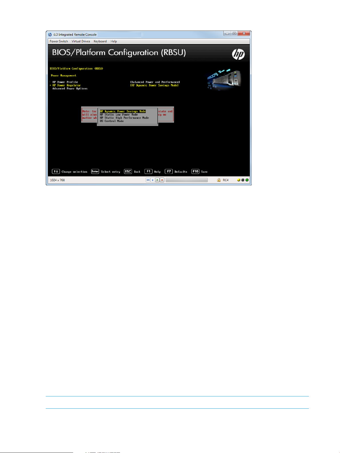
Figure 37 Power Management — HP Power Regulator screen
Configuring Advanced Power Management Options
To configure advanced power options:
1. From the System Utilities screen, select System Configuration→BIOS/Platform Configuration
(RBSU)→Power Management→Advanced Power Management Options and press Enter. The
Power Management screen appears.
2. Select one of the following options:
• “Setting Intel QPI Link Power Management” (page 46)
• “Setting Intel QPI Link Frequency” (page 47)
• “Setting QPI Bandwidth Optimization (RTID)” (page 48)
• “Setting Minimum Processor Idle Power Core State” (page 49)
• “Setting Minimum Processor Idle Power Package State” (page 50)
• “Setting Energy/Performance Bias” (page 51)
• “Setting Maximum Memory Bus Frequency” (page 52)
• “Setting Channel Interleaving” (page 52)
• “Setting Maximum PCI Express Speed” (page 53)
• “Setting Dynamic Power Savings Mode Response” (page 53)
• “Setting Collaborative Power Control” (page 53)`
• “Setting Redundant Power Supply Mode” (page 54)
• “Setting ACPI SLIT Preferences” (page 55)
Setting Intel QPI Link Power Management
NOTE: This option is available on servers with multiple Intel processors.
46 Accessing the System Configuration Menu
Page 47

Place the Quick Path Interconnect links into a low power state when the links are not being utilized.
This lowers power usage with minimal performance effect. You can only configure this feature if
two or more CPUs are present.
To configure Intel QPI Link Power Management:
1. From the System Utilities screen, select System Configuration→BIOS/Platform Configuration
(RBSU)→Power Management→Advanced Power Options→Intel QPI Link Power Management
and press Enter.
2. Select one of the following options:
• Enabled (default)
• Disabled
3. Press F10 to save your selection.
Figure 38 Advanced Power Management — Intel QPI Link Power Management screen
Setting Intel QPI Link Frequency
NOTE: This option is available on Gen8 with multiple Intel processors.
You can set the QPI link frequency to a low speed. Running at a lower frequency can reduce power
consumption; however, it can also impact system performance. You can only configure this option
if two or more CPUs are present.
To configure Intel QPI Link Frequency:
1. From the System Utilities screen, select System Configuration→BIOS/Platform Configuration
(RBSU)→Power Management→Advanced Power Options→Intel QPI Link Frequency and press
Enter.
2. Select one of the following options:
• Auto (default)
• Min QPI Speed
3. Press F10 to save your selection.
Accessing the BIOS/Platform Configuration (RBSU) menu 47
Page 48

Figure 39 Intel QPI Link Frequency screen
Setting QPI Bandwidth Optimization (RTID)
NOTE: This option is available on Gen8 with Intel processors.
The QPI link between two processors provides the best performance for most applications.
To set QPI Bandwidth Optimization:
1. From the System Utilities screen, select System Configuration→BIOS/Platform Configuration
(RBSU)→Power Management→Advanced Power Options→QPI Bandwidth Optimization (RTID)
and press Enter.
2. Select one of the following options:
• Balanced (default)—Provides the best performance for most applications and benchmarks.
• Optimized for I/O (Alternate RTID)—Increases bandwidth from I/O devices, such as GPUs
that rely on direct access to system memory. This option is only configurable if two or
more CPUs are present.
3. Press F10 to save your selection.
NOTE: Setting this option to Optimized for I/O can have a negative impact on memory and
system performance.
48 Accessing the System Configuration Menu
Page 49

Figure 40 QPI Bandwidth Optimization screen
Setting Minimum Processor Idle Power Core State
Select the lowest processor idle power state (C-state) that the operating system uses. The higher
the C-state, the lower the power usage of the idle power state. C6 is the lowest power idle state
supported by the processor. Configure this option only when HP Power Profile is set to “Custom.”
To set minimum processor idle power core state:
1. From the System Utilities screen, select System Configuration→BIOS/Platform Configuration
(RBSU)→Power Management→Advanced Power Options→Minimum Processor Idle Power
Core State and press Enter.
2. Select one of the following options:
• C6 State (default — lowest)
• C3 State
• C1E State
• No C-states
3. Press F10 to save your selection.
Accessing the BIOS/Platform Configuration (RBSU) menu 49
Page 50

Figure 41 Advanced Power Management — Minimum Processor Idle Power Core State screen
Setting Minimum Processor Idle Power Package State
NOTE: This option is available on servers with Intel processors.
Configure the lowest processor idle power state (C-state). The processor automatically transitions
into package C-states based on the Core C-states in which cores on the processor have transitioned.
The higher the package C-state, the lower the power usage of that idle package state. Package
C6 (non-retention) is the lowest power idle package state supported by the processor. Configure
this option only when HP Power Profile is set to Custom.
To set minimum processor idle power package state:
1. From the System Utilities screen, select System Configuration→BIOS/Platform Configuration
(RBSU)→Power Management→Advanced Power Options→Minimum Processor Idle Power
Package State and press Enter.
2. Select one of the following options:
• Package C6 (retention) State
• Package C6 (non-retention) State
• No Package State
3. Press F10 to save your selection.
50 Accessing the System Configuration Menu
Page 51

Figure 42 Advanced Power Management — Minimum Processor Idle Power Package State screen
Setting Energy/Performance Bias
Configure several processor subsystems to optimize the processor’s performance and power usage.
Configure this option only if the HP Power Profile is set to “Custom.”
To set energy/performance bias:
1. From the System Utilities screen, select System Configuration→BIOS/Platform Configuration
(RBSU)→Power Management→Advanced Power Options→Energy/Performance Bias and
press Enter.
2. Select one of the following options:
• Maximum Performance—Provides the highest performance and lowest latency. Only use
this option for environments that are not sensitive to power consumption.
• Balanced Performance (default)—Provides optimum power efficiency and is recommended
for most environments.
• Balanced Power—Provides optimum power efficiency based on server utilization.
• Power Savings Mode—For environments that are power sensitive and can accept reduced
performance.
3. Press F10 to save your selection.
Accessing the BIOS/Platform Configuration (RBSU) menu 51
Page 52

Figure 43 Advanced Power Management — Energy/Performance Bias screen
Setting Maximum Memory Bus Frequency
Configure the system to run memory at a lower maximum speed than that supported by the installed
processor and DIMM configuration. Setting this option to Auto configures the system to run memory
at the maximum speed supported by the system configuration. Configure this option only when HP
Power Profile is set to Custom.
To set the maximum memory bus frequency:
1. From the System Utilities screen, select System Configuration→BIOS/Platform Configuration
(RBSU)→Power Management→Advanced Power Options→Maximim Memory Bus Frequency
and press Enter.
2. Select one of the following options:
• Auto (default)
• 1333MHz
• 1066MHz
• 800MHz
3. Press F10 to save your selection.
NOTE: Options vary depending on the installed processor.
Setting Channel Interleaving
Modify the level of interleaving for which the memory system is configured. Typically, higher levels
of memory interleaving result in maximum performance. However, reducing the level of interleaving
can result in power savings. Configure this option only when HP Power Profile is set to “Custom.”
To set channel interleaving:
1. From the System Utilities screen, select System Configuration→BIOS/Platform Configuration
(RBSU)→Power Management→Advanced Power Options→Channel Interleaving and press
Enter.
52 Accessing the System Configuration Menu
Page 53

2. Select one of the following options:
• Enabled (default)
• Disabled
3. Press F10 to save your selection.
Setting Maximum PCI Express Speed
If a PCI-Express device does not run properly at its maximum speed, reducing the speed can address
this issue. This option lets you lower the maximum PCI-express speed in which the server allows
PCI-express devices to operate. It can be useful in addressing issues with problematic PCI-express
devices. Setting this value to Maximum Supported configures the platform to run at the maximum
speed supported by the platform or the PCI-e device (whichever is lower). Configure this option
only when HP Power Profile is set to Custom.
To set maximum PCI Express Speed:
1. From the System Utilities screen, select System Configuration→BIOS/Platform Configuration
(RBSU)→Power Management→Advanced Power Options→Maximum PCI Express Speed and
press Enter.
2. Select one of the following options:
• Maximum Supported (default)—Configures the platform to run at the maximum speed
supported by the platform or the PCIe device (whichever is lower).
• PCIe Generation 1.0—Configures the platform to run at the lowest speed possible in the
PCIe links, which is PCIe Generation 1.0. When setting this option to PCIe Generation
1.0, performance of high-end cards such as 10GbE NIC Cards and I/O Accelerators
may be affected.
3. Press F10 to save your selection.
NOTE: This option works in conjunction with the PCIe Gen 3 Control setting. When setting the
PCIe Gen 3 Control to Enabled, this Maximum PCI Express Speed option must be set to Maximum
Supported.
Setting Dynamic Power Savings Mode Response
Enable the system ROM to control processor performance and power state depending on the
processor workload. This option configures the response time for switching between these states.
Configure this option only when HP Power Profile is set to Custom.
To set dynamic power savings mode response:
1. From the System Utilities screen, select System Configuration→BIOS/Platform Configuration
(RBSU)→Power Management→Advanced Power Options→Dynamic Power Savings Mode
Response and press Enter.
2. Select one of the following options:
• Fast (default)—Optimal for most workloads where low latency response to an increase
in processor demand is a requirement.
• Slow—Optimal for workloads where a longer latency response to an increase in processing
demand is an acceptable tradeoff for reduced power consumption. Depending on the
processor workload, selecting this option can negatively affect performance.
3. Press F10 to save your selection.
Setting Collaborative Power Control
For operating systems that support the Processor Clocking Control (PCC) Interface, enabling this
option allows the Operating System to request processor frequency changes (even if the server
has the Power Regulator option configured for Dynamic Power Savings Mode). For Operating
Systems that do not support the PCC Interface, or when the Power Regulator Mode is not configured
Accessing the BIOS/Platform Configuration (RBSU) menu 53
Page 54
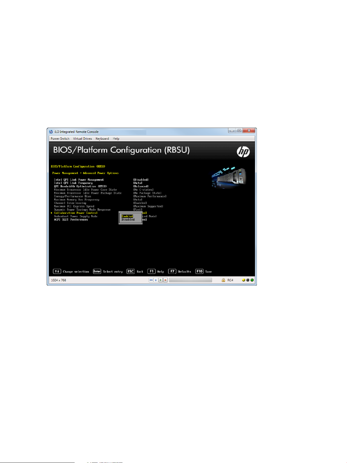
for Dynamic Power Savings Mode, this option has no impact to system operation. Configure this
option only if the HP Power Profile is set to Custom.
To set the Collaborative Power Control:
1. From the System Utilities screen, select System Configuration→BIOS/Platform Configuration
(RBSU)→Power Management→Advanced Power Options→Collaborative Power Control and
press Enter.
2. Select one of the following options:
• Enabled (default)
• Disabled
3. Press F10 to save your selection.
Figure 44 Advanced Power Management — Collaborative Power Control screen
Setting Redundant Power Supply Mode
Configure how the system handles redundant power supply configurations.
To set redundant power supply mode:
1. From the System Utilities screen, select System Configuration→BIOS/Platform Configuration
(RBSU)→Power Management→Advanced Power Options→Redundant Power Supply Mode
and press Enter.
2. Select one of the following options:
• Balanced Mode (default)—Shares the power delivery equally between all installed power
supplies.
• All High Efficiency Mode—Configures the most power-efficient operation with redundant
power supplies by keeping half of the power supplies in standby mode at lower usage
levels.
• High Efficiency Mode—Selects which power supply is to be placed in standby. The system
automatically chooses between the odd or even power supply based on the server’s serial
number to achieve a semi-random distribution within a group of systems.
3. Press F10 to save your selection.
54 Accessing the System Configuration Menu
Page 55

Setting ACPI SLIT Preferences
The ACPI SLIT (System Locality Information Table) describes the relative access times between
processors, memory subsystems, and I/O subsystems. Operating systems that support the SLIT can
use this information to improve performance by allocating resources and workloads more efficiently.
To set ACPI SLIT Preferences:
1. From the System Utilities screen, select System Configuration→BIOS/Platform Configuration
(RBSU)→Power Management→Advanced Power Options→ACPI SLIT Preferences and press
Enter.
2. Select one of the following options:
• Enabled
• Disabled (default)
3. Press F10 to save your selection.
Figure 45 Advanced Power Management — ACPI SLIT Preferences screen
Setting Embedded and Add-in Devices
Enable or disable embedded and add-in devices. Disabling devices re-allocates the resources
(memory, I/O, and ROM space and power) that are normally allocated to the device.
By default, all devices are enabled.
To set embedded and add-in devices:
1. From the System Utilities screen, select System Configuration→BIOS/Platform Configuration
(RBSU)→PCI Device Enabled/Disable and press Enter.
2. Select a device on the system from the list and press Enter.
3. Select either Enable or Disable and press Enter.
4. Press F10 to save your selection.
Accessing the BIOS/Platform Configuration (RBSU) menu 55
Page 56

Figure 46 PCI Device Enable/Disable screen
Setting the System Date and Time
Set the system time and date on the server.
To set the system date and time on the server:
1. From the System Utilities screen, select System Configuration→BIOS/Platform Configuration
(RBSU)→Date and Time and press Enter. The Date and Time screen appears.
2. Select a device on your system from the list and press Enter.
3. Select Date (mm-dd-yyyy) and press Enter to set the date. Enter the date in a month-day-year
(mm-dd-yyyy) format.
4. Select Time (hh:mm:ss) and press Enter to the time. Enter the time in a 24–hour format
(hh:mm:ss) format.
5. Press F10 to save your selection.
56 Accessing the System Configuration Menu
Page 57

Figure 47 Date and Time screen
Accessing the Server Availability menu
Enable the automatic server recovery status and timeout, set thermal shutdown, configure
power-on-self-test, set the power button mode, and set the power-on delay.
To access the Server Availability menu:
1. From the System Utilities screen, select System Configuration→BIOS/Platform Configuration
(RBSU)→Server Availability and press Enter. The Server Availability screen appears.
2. Select any of the following options:
• “Enabling the ASR (Automatic Server Recovery) Status” (page 57)
• “Setting ASR (Automatic Server Recovery) Timeout” (page 58)
• “Setting Thermal Shutdown” (page 59)
• “Remotely Powering On the Server” (page 60)
• “Configuring the POST (Power-On-Self-Test) F1 Prompt” (page 61)
• “Setting Power Button Mode” (page 62)
• “Setting Automatic Power-On” (page 63)
• “Setting Power-On Delay” (page 64)
Enabling the ASR (Automatic Server Recovery) Status
Configure the system to automatically reboot if the server locks up. The ASR Status option is a
toggle setting that enables or disables ASR. If you set this option to disabled, no ASR features
function. The System Management driver must be loaded to use this option.
To set the ASR status:
1. From the System Utilities screen, select System Configuration→BIOS/Platform Configuration
(RBSU)→Server Availability and select ASR Status and press Enter.
2. Select Enable or Disable.
3. Press F10 to save your selection.
Accessing the BIOS/Platform Configuration (RBSU) menu 57
Page 58

Figure 48 Server Availability — ASR Status screen
Setting ASR (Automatic Server Recovery) Timeout
If Automatic Server Recovery is enabled, this option lets you set the time to wait before rebooting
the server in the event of an operating system crash or server lockup. When the server has not
responded in the selected amount of time, the server automatically reboots.
To set ASR timeout:
1. From the System Utilities screen, select System Configuration→BIOS/Platform Configuration
(RBSU)→Server Availability and select ASR Timeout and press Enter.
2. Select one of the following time increments:
• 5 minutes
• 10 minutes (default)
• 15 minutes
• 20 minutes
• 30 minutes
3. Press F10 to save your selection.
58 Accessing the System Configuration Menu
Page 59

Figure 49 Server Availability — ASR Timeout screen
Setting Thermal Shutdown
Initiate a shutdown due to non-redundant fan failures or temperature increases beyond the pre-set
threshold. If disabled, the System Management Driver ignores thermal events and the system
immediately powers off in data-destructive situations.
To set thermal shutdown:
1. From the System Utilities screen, select System Configuration→BIOS/Platform Configuration
(RBSU)→Server Availability and select Thermal Shutdown and press Enter.
2. Select one of the following options:
• Enabled—Allows the Advanced System Management Driver to initiate a system shutdown
when the temperature reaches within 5 degrees of critical level.
• Disabled (default)—Allows the Advanced System Management Driver to shut down the
system at critical level.
3. Press F10 to save your selection.
Accessing the BIOS/Platform Configuration (RBSU) menu 59
Page 60

Figure 50 Server Availability — Thermal Shutdown screen
Remotely Powering On the Server
Configure the server to power on remotely when it receives a special packet. If you enable the
Wake-On LAN option, the system can be powered up remotely using a WOL-capable NIC. This
option requires a NIC, NIC driver, and operating system that are WOL-capable. If you choose
the enabled option, the following caution appears:
When enabling Wake-on LAN, remove all power cords before adding or
removing any adapters. Some adapters can cause the system to power on
when added or removed.
To remotely power-on the server:
1. From the System Utilities screen, select System Configuration→BIOS/Platform Configuration
(RBSU)→Server Availability and select Wake-On LAN and press Enter.
2. Select one of the following options:
• Enabled
• Disabled (default)
3. Press F10 to save your selection.
60 Accessing the System Configuration Menu
Page 61

Figure 51 Server Availability — Wake On LAN screen
Configuring the POST (Power-On-Self-Test) F1 Prompt
Configure the system to display the F1 key in the server POST screen. If an error is encountered,
press the F1 key to continue with the server power-up sequence.
To configure the POST F1 prompt:
1. From the System Utilities screen, select System Configuration→BIOS/Platform Configuration
(RBSU)→Server Availability and select POST F1 Prompt and press Enter.
2. The following options are available:
• Delayed 20 Seconds— if an error occurs, the system pauses for 20 seconds at the F1
prompt, and then continues to boot the OS.
• Delayed 2 Seconds — if an error occurs, the system pauses for 2 seconds at the F1
prompt, and then continues to boot the OS.
• Disabled — if an error occurs, the system bypasses the F1 prompt and continues to boot.
3. A series of system tests executes during POST before continuing with the following:
• If failures occur that allow the system to continue operating, the system continues to boot
and then posts a message.
• If critical components fail or are missing, the server attempts to boot. If it can boot, it posts
a message and an F1 prompt.
• If the system cannot run with the missing or failed components, it halts until those
components are replaced.
4. Press F10 to save your selection.
Accessing the BIOS/Platform Configuration (RBSU) menu 61
Page 62

Figure 52 Server Availability — POST F1 Prompt screen
Setting Power Button Mode
Disabling this option disables the momentary power button functionality. This option does not effect
the four-second power button override or the remote power control functionality.
To set power button mode:
1. From the System Utilities screen, select System Configuration→BIOS/Platform Configuration
(RBSU)→Server Availability and select Power Button Mode and press Enter.
2. Select one of the following options:
• Enabled (default)—Enables the momentary power button functionality.
• Disabled—Disables the momentary power button functionality.
3. Press F10 to save your selection.
62 Accessing the System Configuration Menu
Page 63

Figure 53 Server Availability — Power Button Mode screen
Setting Automatic Power-On
Configure the server to automatically power on when AC power is applied to the system. By default,
the system returns to its previous power state when AC power is restored after an AC power loss.
This option allows overriding this behavior such that the system always returns to the "on" state
whenever power is applied (even if the system had been in the off state when power was lost).
To set automatic power-on:
From the System Utilities screen, select System Configuration→BIOS/Platform Configuration
(RBSU)→Server Availability and select Automatic Power-On and press Enter.
1. Select one of the following options:
• Always Power On—Configures the system to return to the “on” state when AC power is
restored, even if the system had been in the “off” state when power was lost.
• Always Power Off—Configures the system to return to the “off” state when AC power is
restored, even if the system had been in the “on” state when power was lost.
• Restore Last Power State (default)—Configures the system to return to the previous power
state (on or off) when AC power is restored.
2. Press F10 to save your selection.
Accessing the BIOS/Platform Configuration (RBSU) menu 63
Page 64

Figure 54 Server Availability — Automatic Power-On screen
Setting Power-On Delay
Delay the server from turning on for the desired time. Pressing the power button (using the iLO
Virtual Power Button) Wake-ON LAN events and RTC (Real-Time Clock) wake-up events overrides
the delay and immediately turns on the server. This allows staggering when servers power-up after
a power loss to prevent power usage spikes.
To set Power-On Delay:
1. From the System Utilities screen, select System Configuration→BIOS/Platform Configuration
(RBSU)→Server Availability and select Power-On Delay and press Enter.
2. Select one of the following options:
• No Delay (default)
• Random Delay
3. Press F10 to save your selection.
64 Accessing the System Configuration Menu
Page 65

Figure 55 Server Availability — Power-On Delay
Accessing the Server Security menu
Control access to the server and its utilities. This menu sets the power-on and administrator
passwords, set Intelligent Provisioning, and access the Trusted Platform Module.
To access the Server Security menu:
1. From the System Utilities screen, select System Configuration→BIOS/Platform Configuration
(RBSU)→Server Security and press Enter.
2. The following options are available:
• “Setting a Power On Password” (page 66)
• “Setting an Administrator Password” (page 67)
• “Disabling Intelligent Provisioning (F10 Prompt)” (page 69)
• “Configuring Secure Boot” (page 69)
• “Accessing the Trusted Platform Module (TPM)” (page 77)
Accessing the BIOS/Platform Configuration (RBSU) menu 65
Page 66

Figure 56 Server Security screen
Setting a Power On Password
Set a password for accessing the server during the boot process. When powering-on the server,
a prompt appears where you enter the password to continue. To disable or clear the password,
enter the password followed by a / (slash) when prompted to enter the password.
NOTE: In the event of an Automatic Server Recovery (ASR) reboot, the power-on password is
bypassed and the server boots normally.
To set a power-on password:
1. From the System Utilities screen, select System Configuration→BIOS/Platform Configuration
(RBSU)→Server Security and select Set Power On Password and press Enter.
2. Enter your password and press Enter.
A message appears telling you the password setting was successful.
3. Follow these password requirements:
• Seven characters maximum.
• Can be any combination of numbers, letters, and special characters.
4. Press F10 to save your entry.
66 Accessing the System Configuration Menu
Page 67

Figure 57 Server Security — Set Power On Password screen
Setting an Administrator Password
Set an administrator password to protect the server configuration. If enabled, you are prompted
for this password before being allowed to modify the configuration.
To set the administrator password:
1. From the System Utilities screen, select System Configuration→BIOS/Platform Configuration
(RBSU)→Server Security and select Set Admin Password and press Enter.
2. Enter the password and press Enter.
3. Confirm the password and press Enter.
A message appears confirming the password setting was successful.
4. Press F10 to save your entry.
Accessing the BIOS/Platform Configuration (RBSU) menu 67
Page 68

Figure 58 Server Security — Set Admin Password screen
Disabling the F11 One-Time Boot Menu
This menu specifies a specific boot override option for this boot only. This option does not modify
the normal boot order settings. By default, you can boot directly into the One-Time Boot menu in
the System Utilities by pressing F11 in the HP ProLiant main screen after a server reboot. See
“Configuring a One-Time Boot Menu” (page 139) for more details about options in the One-Time
Boot menu. Disable this option if needed.
To disable the F11 One-Time Boot menu:
1. From the System Utilities screen, select System Configuration→BIOS/Platform Configuration
(RBSU)→Server Security→F11 Boot Menu Prompt and press Enter.
2. Select one of the following options:
• Enabled (default)
• Disabled
3. Press F10 to save your selection.
4. During the next server reboot, F11 is disabled.
68 Accessing the System Configuration Menu
Page 69

Figure 59 Server Security — F11 Boot Menu Prompt
Disabling Intelligent Provisioning (F10 Prompt)
This option disables the Intelligent Provisioning functionality. If this option is disabled, you are
prevented from entering the Intelligent Provisioning environment by pressing F10 during server
boot. Set this option to “Enabled” use the Intelligent Provisioning functionality.
To disable Intelligent Provisioning (F10 Prompt):
1. From the System Utilities screen, select System Configuration→BIOS/Platform Configuration
(RBSU)→Server Security→Intelligent Provisioning (F10 Prompt) and press Enter.
2. Select one of the following options:
• Enabled (default)
• Disabled
3. Press F10 to save your selection.
4. The next time you reboot the server, F10 is disabled.
Configuring Secure Boot
Secure Boot is integrated in the UEFI specification on which the HP implementation of UEFI is based.
Secure Boot is completely implemented in the BIOS and does not require special hardware. It
ensures that each component launched during the boot process is digitally signed and that the
signature is validated against a set of trusted certificates embedded in the UEFI BIOS. Secure Boot
validates the software identity of the following components in the boot process:
• UEFI drivers loaded from PCIe cards
• UEFI drivers loaded from mass storage devices
• Pre-boot UEFI shell applications
• OS UEFI boot loaders
Once enabled, only firmware components and operating systems with boot loaders that have an
appropriate digital signature can execute during the boot process. Only operating systems that
support Secure Boot and have an EFI boot loader signed with one of the authorized keys can boot
when Secure Boot is enabled. For more information about supported operating systems, see the
Accessing the BIOS/Platform Configuration (RBSU) menu 69
Page 70

HP UEFI System Utilities and Shell Release Notes on the HP website (http://www.hp.com/go/
ProLiantUEFI/docs).
A physically present user can customize the certificates embedded in the UEFI BIOS by
adding/removing their own certificates.
Before configuring Secure Boot, select the UEFI Boot Mode. See “Selecting a Boot Mode” (page 41).
Also enable the UEFI Optimized Boot option. See “Setting UEFI Optimized Boot” (page 42) for
details.
To configure Secure Boot:
1. From the System Utilities screen, select System Configuration→BIOS/Platform Configuration
(RBSU)→Server Security and select Secure Boot Configuration and press Enter. The Secure
Boot Configuration screen appears. Current Secure Boot State displays the current secure boot
state (Enabled or Disabled).
2. Select Enable Secure Boot and press Enter to enable the Secure Boot option. A message
appears indicating that a server reboot is needed the new configuration to take effect.
3. Select Secure Boot Mode and press Enter.
4. Select one of the following options:
• Standard Mode—Use the default security certificates that are embedded in the system
BIOS.
• Custom Mode—Customize the secure boot certificates (must be executed by physically
present user). If you select this option, the Secure Boot Custom Mode Options menu
appears. For more information, see “Setting the Secure Boot Custom Mode” (page 71).
NOTE: Changing the default security certificates can cause the system to fail booting
from some devices. It can also cause the system to fail launching certain system software
such as Intelligent Provisioning.
5. Press F10 to save your selection.
Figure 60 Server Security — Secure Boot Mode screen
70 Accessing the System Configuration Menu
Page 71

Setting the Secure Boot Custom Mode
If you select the “Custom Mode” for Secure Boot mode, the Secure Boot Custom Mode Options
menu appears. From this menu, select the Platform Key (PK) Options, Key Exchange Key (KEK)
Options, Allowed Signatures Database (DB) Options, and Forbidden Signatures Database (DBX)
Options.
Figure 61 Server Security — Secure Boot Custom Mode Options screen
1. Select Secure Boot Mode Options and press Enter.
2. Select one of the following options:.
• Platform Key (PK) Options—Select this option to enroll a Platform Key (PK). The file must
be in DER-encoded certificate format. See “Enrolling a Platform Key (PK)” (page 72) to
proceed.
• Key Exchange Key (KEK) Options—Select this option to enroll a Key Exchange Key (KEK).
The file must be in DER-encoded certificate format. For more information, see “Enrolling
a Key Exchange Key (KEK)” (page 73) to proceed.
• Allowed Signatures Database (DB) Options—Select this option to enroll an Allowed
Signatures (DB). For more information, see “Allowed Signatures Database (DB) Options”
(page 75) to proceed.
• Forbidden Signatures Database (DBX) Options—Select this option to enroll a Forbidden
Signatures (DBX). For more information, see “Forbidden Signatures Database (DBX)
Options” (page 76) to proceed.
Accessing the BIOS/Platform Configuration (RBSU) menu 71
Page 72

Figure 62 Server Security — Custom Secure Boot Options screen
Enrolling a Platform Key (PK)
A Platform Key protects the next key from uncontrolled modification. Select this option to enter the
Platform Key (PK) options menu. You can enroll or delete the PK certificate. The file must be in
DER-encoded certificate format.
To enroll a Platform Key:
1. Select Platform Key (PK) Options→Enroll PK and press Enter.
2. Select Enroll PK using File and press Enter. You can read the PK certificate from a file on an
attached media device. Supported formats include .der, .cer, and .crt.
3. Select Commit changes and exit to save your changes.
72 Accessing the System Configuration Menu
Page 73

Figure 63 Server Security—Enroll PK screen
Deleting a Platform Key
You can delete a Platform Key. This requires an immediate system reboot. Deleting the PK forces
Secure Boot to be disabled until you enroll a new PK.
To delete a Platform Key:
1. Select Platform Key (PK) Options→Delete Platform Key (PK) and press Enter
2. Select a key from the list.
3. Press Enter (Yes) in the message prompt to delete the Key or ESC to cancel.
Enrolling a Key Exchange Key (KEK)
The Key Exchange Key protects the signature database from unauthorized modifications. No
changes can be made to the signature database without the private portion of this key. Select this
option to enter the Key Exchange Key (KEK) Options menu. You can enroll or delete the KEK
certificates. The file must be in DER-encoded certificate format.
To enroll a Key Exchange Key:
1. Select Key Exchange Key (KEK) Options→Enroll KEK Entry and press Enter.
2. Select Enroll KEK using File and press Enter. You can read the KEK certificate from a file on
an attached media device. Supported formats include .der, .cer, and .crt.
3. Select Commit changes and exit to save your changes.
Accessing the BIOS/Platform Configuration (RBSU) menu 73
Page 74

Figure 64 Server Security—Enroll KEK Entry screen
Figure 65 Server Security—Enroll KEK using File screen
Enrolling a Key or Signature using a Signature GUID
You can optionally enroll a Key or Signature using a GUID.
To enroll a Key or Signature using a Signature GUID:
1. Select Key Exchange Key (KEK) Options→Signature GUID (optional) and press Enter.
74 Accessing the System Configuration Menu
Page 75

2. Enter the optional security certificate Signature GUID and press Enter. Enter the data in the
following GUID format (36 characters): 11111111-2222-3333-4444-1234567890ab.
• For Hewlett Packard certificates, enter F5A96B31-DBA0-4faa-A42A-7A0C9832768E
• For Microsoft certificates, enter 77fa9abd-0359-4d32-bd60-28f4e78f784b
• For SUSE certificates, enter 2879c886-57ee-45cc-b126-f92f24f906b9
3. Select Commit changes and exit to save your changes.
Deleting a Key Exchange Key
Select this option to delete a new entry in the Key Exchange Key (KEK) security database. Important:
Changing the default security certificates can cause the system to fail booting from some devices,
or to fail launching certain software such as Intelligent Provisioning.
To delete a Key Exchange Key:
1. Select Platform Key (PK) Options→Delete Key Exchange Key (KEK) and press Enter
2. Select a key to delete from the list.
3. Press Enter (Yes) in the message prompt to delete the Key or ESC to cancel.
Allowed Signatures Database (DB) Options
The database maintains signatures of codes that are authorized to run on the platform. Select this
option to enter the Allowed Signatures (DB) Options menu. You can enroll or delete the DB
signatures.
To enroll a Signature Database.
1. Select Allowed Signatures Database (DB) Options→Enroll Signature and press Enter.
2. Select Enroll Signature using File and press Enter.
3. Select Commit changes and exit to save your changes.
Figure 66 Server Security—Enroll Signature screen
Accessing the BIOS/Platform Configuration (RBSU) menu 75
Page 76

Figure 67 Server Security—Enroll DB Signature using File screen
Forbidden Signatures Database (DBX) Options
The database maintains signatures of codes that are forbidden to run on the platform. Select this
option to enter the Forbidden Signatures (DBX) Options menu. You can enroll or delete the DBX
signatures.
To enroll a Forbidden Signature Database (DBX):
1. Select Forbidden Signatures Database (DB) Options→Enroll Signature and press Enter.
2. Select Enroll Signature using File and press Enter.
3. Select Commit changes and exit to save your changes.
76 Accessing the System Configuration Menu
Page 77

Figure 68 Server Security—Enroll DBX Signature screen
Figure 69 Server Security—Enroll DBX Signature using File screen
Accessing the Trusted Platform Module (TPM)
Trusted Platform Module (TPM) allows the firmware and operating system to take measurements
of all phases of the booting process. For information on installing and enabling the TPM module
option, see the user documentation for your server model and the Data security in HP ProLiant
servers using the Trusted Platform Module and Microsoft Windows BitLocker Drive Encryption white
paper: http://h20000.www2.hp.com/bc/docs/support/SupportManual/c01681891/
c01681891.pdf.
To access the Trusted Platform Module:
Accessing the BIOS/Platform Configuration (RBSU) menu 77
Page 78

1. From the System Utilities screen, select System Configuration→BIOS/Platform Configuration
(RBSU)→Server Security and select Trusted Platform Module Options and press Enter.
2. For servers configured with an optional TPM, the following configuration option is available:
• “Setting TPM Functionality” (page 78)
IMPORTANT: TPM menus appear only if the TPM kit is installed.
Setting TPM Functionality
This option controls Trusted Platform Module functionality at startup. Options include:
• Enabled—Enables the TPM and BIOS secure startup. The TPM is fully functional in this mode.
• Disabled (default)—Disables the BIOS secure startup, but still allows the TPM to be visible to
the operating system. The TPM functionality is limited, but can respond to most commands in
this mode. Selecting Disabled might prevent the server from booting to a TPM-aware operating
system.
CAUTION: A TPM locks all data access if proper procedures are not followed for modifying the
server, including: updating system or option firmware, replacing hardware such as the system
board and hard drive, or modifying TPM OS settings.
Intelligent Provisioning Quick Configs settings and corresponding RBSU settings
Intelligent Provisioning Quick Configs options provide the capability to select a basic policy for
performance versus power usage, without having to configure individual settings through RBSU
menus.
For more information about the Intelligent Provisioning Quick Configs profiles and their
corresponding option settings, see the HP Intelligent Provisioning User Guide.
Accessing the BIOS Serial Console and EMS Console
Through BIOS Serial Console and EMS console redirection, you can view POST error messages
and run RBSU remotely through a serial connection to the server COM port or iLO Virtual Serial
port. The remote server does not require a keyboard or mouse.
NOTE: Some languages or characters can require a specific emulation mode.
To access BIOS Serial Console and EMS menu:
1. From the System Utilities screen, select System Configuration→BIOS/Platform Configuration
(RBSU)→BIOS Serial Console and EMS and press Enter.
2. The following configuration options are available:
• “Setting BIOS Serial Console Port” (page 79)
• “Setting BIOS Serial Console Emulation Mode” (page 80)
• “Setting BIOS Serial Console Baud Rate” (page 81)
• “Setting the EMS Console” (page 82)
78 Accessing the System Configuration Menu
Page 79

Figure 70 BIOS Serial Console and EMS screen
Setting BIOS Serial Console Port
You can re-direct video and keystrokes through the serial port to OS boot. This option can interfere
with non-terminal devices attached to the serial port. In this case, set this option to “Disabled.”
IMPORTANT: This option is not supported under RBSU on Japanese or Simplified Chinese systems.
To set the BIOS serial console port:
1. From the System Utilities screen, select System Configuration→BIOS/Platform Configuration
(RBSU)→BIOS Serial Console and EMS and select BIOS Serial Console Port and press Enter.
2. Select one of the following options:
• Auto
• Disabled (default for older servers)
• Physical Serial Port
• Virtual Serial Port
3. Press F10 to save your selection.
NOTE: Connect a null modem cable to the serial port/COM port on which BIOS Serial Console
is enabled.
Accessing the BIOS/Platform Configuration (RBSU) menu 79
Page 80

Figure 71 BIOS Serial Console and EMS — BIOS Serial Console Port screen
Setting BIOS Serial Console Emulation Mode
You can select an emulation mode type. The selected option depends on the emulation you want
to use in your serial terminal program (for example, HyperTerminal or PuTTY). The BIOS emulation
mode must match the selected mode in the terminal program.
To set the BIOS Serial Console Emulation Mode:
1. From the System Utilities screen, select System Configuration→BIOS/Platform Configuration
(RBSU)→BIOS Serial Console and EMS and select BIOS Serial Console Emulation Mode and
press Enter.
2. Select one of the following options:
• VT100 (default)
• ANSI
• VT100+
3. Press F10 to save your selection.
80 Accessing the System Configuration Menu
Page 81

Figure 72 BIOS Serial Console and EMS — BIOS Serial Console Emulation Mode screen
Setting BIOS Serial Console Baud Rate
You can set the transfer rate at which data is transmitted through the serial port.
To set the BIOS Serial Console Emulation Port:
1. From the System Utilities screen, select System Configuration→BIOS/Platform Configuration
(RBSU)→BIOS Serial Console and EMS and select BIOS Serial Console Baud Rate and press
Enter.
2. Select one of the following baud rates:
• 9600
• 19200
• 57600
• 115200 (default)
3. Press F10 to save your selection.
Accessing the BIOS/Platform Configuration (RBSU) menu 81
Page 82

Figure 73 BIOS Serial Console and EMS — BIOS Serial Console Baud Rate screen
Setting the EMS Console
You can configure the ACPI serial port settings, which can be used to configure the Windows
Server Emergency Management (EMS) console to be redirected through a serial port.
When making this selection for redirecting EMS through a network connection, there are two
options:
• If using iLO 4, select the value (COM 1 or COM2) that corresponds to the resources assigned
to the Virtual Serial Port in the Systems option menu.
• If redirecting EMS through a physical serial port, select the value (COM1 or COM2) that
corresponds to the resources assigned to the Embedded Serial Ports in the System Options
menu.
To set the EMS Console:
1. From the System Utilities screen, select System Configuration→BIOS/Platform Configuration
(RBSU)→BIOS Serial Console and EMS and select EMS Console and press Enter.
2. Select one of the following options:
• Disabled (default)
• COM1
• COM2
3. Press F10 to save your selection.
82 Accessing the System Configuration Menu
Page 83

Figure 74 BIOS Serial Console and EMS — EMS Console screen
EMS provides input/output support for all Microsoft Windows kernel components: the loader,
setup, recovery console, OS kernel, blue screens, and the Special Administration Console. The
Special Administration Console is a text mode management console available after Windows
Server 2008 or 2012 OS has initialized.
Microsoft enables EMS in the OS, but EMS must also be enabled in the ROM. When enabled,
EMS assumes the serial port for redirection and can cause interference with other devices attached
to the serial port. To avoid interference, EMS is disabled in the system ROM by default on HP
ProLiant ML and DL servers. If EMS is disabled in Windows Server 2008 or 2012, perform the
following steps to update the boot.ini file:
1. Enable the EMS console on a COM port.
2. Press F10 to save your selection.
3. Reboot the server.
Accessing the Server Asset Text menu
You can modify server information, administrator contact information, service contact information,
and the system startup message.
To access the Server Asset Text menu:
1. From the System Utilities screen, select System Configuration→BIOS/Platform Configuration
(RBSU)→Server Asset Text and press Enter.
2. The following configuration options are available:
• “Entering Server Info Text menu” (page 84)
• “Entering Administrator Information” (page 85)
• “Entering Service Contact Text” (page 86)
• “Entering a Custom POST Message ” (page 87)
Accessing the BIOS/Platform Configuration (RBSU) menu 83
Page 84

Figure 75 Server Asset Text menu screen
Entering Server Info Text menu
These options define reference information for the server administrator.
To enter server information text:
1. From the System Utilities screen, select System Configuration→BIOS/Platform Configuration
(RBSU)→Server Asset Text and select Server Info Text and press Enter.
2. Select one of the following options:
• Server Name—Identifies the server.
• Server Asset Tag—Identifies the server asset number.
• Server Primary OS—Describes the primary OS of the server.
• Server Other Information—Additional text describing the server.
3. Press F10 to save your selection.
84 Accessing the System Configuration Menu
Page 85

Figure 76 Server Asset Text — Server Info Text screen
NOTE: Each of these options can display a maximum of 14 characters. By default, all values
are blank.
Entering Administrator Information
You can define contact information for the server administrator.
To enter administrator information:
1. From the System Utilities screen, select System Configuration→BIOS/Platform Configuration
(RBSU)→Server Asset Text and select Administrator Information and press Enter.
2. Enter an administrator name, phone number, secondary phone number and other information
as follows:
• Administrator Name—Defines the server administrator’s name.
• Administrator Phone Number—Defines the server administrator’s phone number.
• Administrator E-mail Address—Defines the server administrator’s e-mail address.
• Administrator Other Information—Defines additional text relating to the server
administrator.
3. Press F10 to save your selection.
Accessing the BIOS/Platform Configuration (RBSU) menu 85
Page 86

Figure 77 Server Asset Text — Administrator Information screen
NOTE: The number of characters allowed for each entry varies depending on server model. By
default, all values are blank.
Entering Service Contact Text
You can define reference information for the server administrator.
To enter service contact text:
1. From the System Utilities screen, select System Configuration→BIOS/Platform Configuration
(RBSU)→Server Asset Text and select Service Contact Information and press Enter.
2. Enter an administrator name, phone number, secondary phone number and other information
as follows:
• Service Contact Name—Defines the service contact’s name.
• Service Phone Number—Defines the service contact’s phone number.
• Service Contact E-mail Address—Defines the service contact’s e-mail address.
• Service Contact Other Information—Defines additional text relating to the service contact.
3. Press F10 to save your selection.
NOTE: The number of characters allowed for each entry varies depending on server model. By
default, all values are blank.
86 Accessing the System Configuration Menu
Page 87

Figure 78 Server Asset Text — Service Contact Information screen
Entering a Custom POST Message
You can enter a custom message to display during server POST in the HP ProLiant POST screen.
To enter a custom POST message:
1. From the System Utilities screen, select System Configuration→BIOS/Platform Configuration
(RBSU)→Server Asset Text and select Custom POST Message and press Enter.
2. Enter a custom POST message as needed. A maximum of 60 characters is supported. By
default, this value is blank.
3. Press F10 to save your selection.
Accessing the BIOS/Platform Configuration (RBSU) menu 87
Page 88

Figure 79 Server Asset Text — Custom POST Message screen
Accessing Advanced Options
You can display advanced system ROM options, advanced performance tuning options, enable
the embedded video controller for iLO remote video and dual-head video support to functions
properly, override the system power supply requirements, select the fan cooling system, and lock
asset tag information.
To access the Advanced Options menu
1. From the System Utilities screen, select System Configuration→BIOS/Platform Configuration
(RBSU)→Advanced Options and press Enter.
2. The following configuration options are available:
• “Accessing Advanced System ROM Options” (page 89)
• “Accessing Advanced Performance Tuning” (page 103)
• “Setting Video Options” (page 112)
• “Setting Power Supply Requirements Override” (page 113)
• “Setting Thermal Configuration” (page 114)
88 Accessing the System Configuration Menu
Page 89

Figure 80 Advanced Options screen
Accessing Advanced System ROM Options
This menu lets you enter a chassis serial number and product ID, set ROM selection, NMI debug
button, virtual install disk, PCI bus padding, and power-on logo, and consistent device naming.
You can also enable SR-IOV support.
To access advanced system ROM options:
1. From the System Utilities screen, select System Configuration→BIOS/Platform Configuration
(RBSU)→Advanced Options→Advanced System ROM Options and press Enter.
2. The following configuration options are available:
• “Entering a Chassis Serial Number” (page 90)
• “Entering a Product ID” (page 90)
• “Setting ROM Selection” (page 90)
• “Setting NMI Debug Button” (page 91)
• “Setting Virtual Install Disk” (page 92)
• “Setting PCI Bus Padding Options” (page 93)
• “Setting Power-On Logo” (page 94)
• “Enabling SR-IOV Support” (page 95)
• “Setting Consistent Device Naming” (page 96)
• “Setting PCI Express 64-Bit BAR Support” (page 97)
• “Setting PCI Express 64-Bit BAR Support” (page 97)
• “Setting ACPI RASF Table Support” (page 99)
• “Setting ACPI Root Bridge PXM Preferences” (page 100)
• “Configuring Extended Memory Test” (page 101)
• “ACPI RTC Support” (page 102)
Accessing the BIOS/Platform Configuration (RBSU) menu 89
Page 90

Figure 81 Advanced Options — Advanced System ROM options screen
Entering a Chassis Serial Number
After replacing the system board, re-enter the server serial number. Consult a qualified IT service
specialist for assistance in modifying this value.
To enter a chassis serial number:
1. From the System Utilities screen, select System Configuration→BIOS/Platform Configuration
(RBSU)→Advanced Options→Advanced System ROM Options→Serial Number and press Enter.
2. Enter the serial number and press Enter.
3. Press F10 to save your entry.
4. Press Enter to confirm your change.
Entering a Product ID
After replacing the system board, re-enter the server product ID. This ID should match the sticker
located on the chassis.
To enter a product ID:
1. From the System Utilities screen, select System Configuration→BIOS/Platform Configuration
(RBSU)→Advanced Options→Advanced System ROM Options→Product ID and press Enter.
2. Enter the product ID and press Enter.
3. Press F10 to save your entry.
4. Press Enter to confirm your change.
Setting ROM Selection
You can revert the server to a previous BIOS ROM image. The backup image is the BIOS ROM
image that was used prior to the last flash event. This option is supported only on servers with
redundant ROMs.
To set the ROM selection:
1. From the System Utilities screen, select System Configuration→BIOS/Platform Configuration
(RBSU)→Advanced Options→Advanced System ROM Options→ROM Selection and press Enter.
90 Accessing the System Configuration Menu
Page 91

2. The following configuration options are available:
• Use Current ROM (default)
• Switch to Backup ROM
3. Press F10 to save your selection.
Figure 82 Advanced Options — ROM Selection screen
Setting NMI Debug Button
You can enable debug functionality when the system has experienced a software lock-up. The NMI
Debug Button generates an NMI to enable the use of the operating system debugger.
NOTE: When enabled, pressing the NMI Debug Button on the system board during normal
operation halts the system.
To set the NMI debug button:
1. From the System Utilities screen, select System Configuration→BIOS/Platform Configuration
(RBSU)→Advanced Options→Advanced System ROM Options→NMI Debug Button and press
Enter.
2. Select one of the following options:
• Enabled (default)
• Disabled
3. Press F10 to save your selection.
Options include:
• Enabled (default)
• Disabled
Accessing the BIOS/Platform Configuration (RBSU) menu 91
Page 92

Figure 83 Advanced Options —NMI Debug Option screen
Setting Virtual Install Disk
You can control the Virtual Install Disk. The Virtual Install Disk can contain drivers specific to the
server that an operating system can use during installation. If this option is enabled, Microsoft
Windows Server automatically locates required drivers and installs them, eliminating the need for
user intervention and the requirement that a driver be present on external media during operating
system installation. In some cases, the Virtual Install Disk remains visible from the installed operating
system as a read-only drive. During manual installations using Intelligent Provisioning, this option
is automatically enabled.
To further optimize the system, HP recommends updating boot drivers to the latest versions after
the OS installation.
To set the virtual install disk:
1. From the System Utilities screen, select System Configuration→BIOS/Platform Configuration
(RBSU)→Advanced Options→Advanced System ROM Options→Virtual Install Disk and press
Enter.
2. Select one of the following options:
• Enabled—Creates a visible read-only virtual disk (256MB)
• Disabled (default)
3. Press F10 to save your selection.
NOTE: When Intelligent Provisioning software is updated, this Virtual Install Disk is automatically
updated.
92 Accessing the System Configuration Menu
Page 93
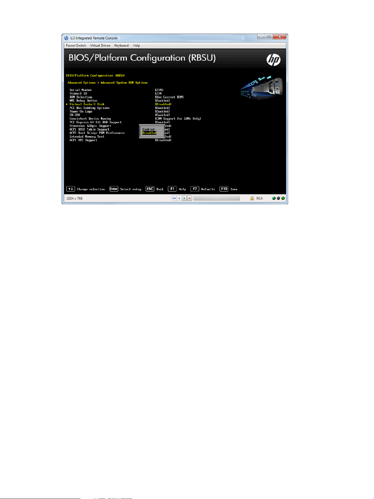
Figure 84 Advanced Options —Virtual Install Disk screen
Setting PCI Bus Padding Options
You can disable the default PCI Bus padding where each expansion slot is provided with an extra
PCI Bus number. By default, the System BIOS pads one PCI bus per expansion slot to allow
expansion cards with PCI-PCI bridges to not effect current bus numbering schemes. Disabling this
option works around issues with certain expansion cards. It is not recommended to disable this
option unless a specific issue is encountered.
HP recommends disabling this option only when encountering a specific issue.
To set PCI Bus padding options:
1. From the System Utilities screen, select System Configuration→BIOS/Platform Configuration
(RBSU)→Advanced Options→Advanced System ROM Options→PCI Bus Padding Options and
press Enter.
2. Select one of the following options:
• Enabled (default)
• Disabled
3. Press F10 to save your selection.
Accessing the BIOS/Platform Configuration (RBSU) menu 93
Page 94

Figure 85 Advanced Options — PCI Bus Padding Options
Setting Power-On Logo
This option controls the display of the logo during system boot. This is an aesthetic modification
only and does not affect the system boot times.
To set power-on logo:
1. From the System Utilities screen, select System Configuration→BIOS/Platform Configuration
(RBSU)→Advanced Options→Advanced System ROM Options→Power-On Logo and press
Enter.
2. Select one of the following options:
• Enabled (default)
• Disabled
3. Press F10 to save your selection.
94 Accessing the System Configuration Menu
Page 95

Figure 86 Advanced Options — Power-On Logo screen
Enabling SR-IOV Support
You can create virtual instances of a PCI device for use under a Hypervisor-based operating system.
When you create virtual instances, the BIOS allocates more PCI resources to the PCI devices.
Enable this option for a PCIe device or operating system that supports SR-IOV.
To enable SR-IOV support:
1. From the System Utilities screen, select System Configuration→BIOS/Platform Configuration
(RBSU)→Advanced Options→Advanced System ROM Options→SR-IOV and press Enter.
2. Select one of the following options:
• Enabled (default)
• Disabled
3. Press F10 to save your selection.
Accessing the BIOS/Platform Configuration (RBSU) menu 95
Page 96

Figure 87 Advanced Options — SR-IOV screen
Setting Consistent Device Naming
You can select the level of Consistent Device Naming. On supported operating systems, NIC ports
are named based on their location in the system.
To set device naming:
1. From the System Utilities screen, select System Configuration→BIOS/Platform Configuration
(RBSU)→Advanced Options→Advanced System ROM Options→Consistent Device Naming and
press Enter.
2. Select one of the following options:
• CDN Support for LOMs only—Embedded NICs and FlexibleLOM (not NICs installed in
expansion slots) are named based on their location in the system.
• Disabled (default)—All NIC ports are named based on their location in the system.
3. Press F10 to save your selection.
NOTE: Existing NIC connections retain their names until reinstalled under the OS environment.
96 Accessing the System Configuration Menu
Page 97

Figure 88 Advanced Options — Consistent Device Naming screen
Setting PCI Express 64-Bit BAR Support
Force PCIe resources to use 32–bit MMIO addressing. Disabling 64–bit BAR support might be
necessary for certain legacy option card device to function properly when Boot Mode is set to
“Legacy Boot.”
To set PCI express 64-bit BAR support:
1. From the System Utilities screen, select System Configuration→BIOS/Platform Configuration
(RBSU)→Advanced Options→Advanced System ROM Options→PCI Express 64-Bit BAR Support
and press Enter.
2. Select one of the following options:
• Enabled (default)
• Disabled
3. Press F10 to save your selection.
Accessing the BIOS/Platform Configuration (RBSU) menu 97
Page 98

Figure 89 PCI Express 64–Bit BAR Support screen
Setting Processor X2Apic Support
This option enables support for processor X2Apic devices. Enabling this option generates ACPI
X2Apic structures.
To set processor X2Apic support:
1. From the System Utilities screen, select System Configuration→BIOS/Platform Configuration
(RBSU)→Advanced Options→Advanced System ROM Options→Processor X2Apic Support and
press Enter.
2. Select one of the following options:
• Enabled
• Disabled (default)
3. Press F10 to save your selection.
98 Accessing the System Configuration Menu
Page 99

Figure 90 Processor X2Apic Support
Setting ACPI RASF Table Support
This option enables the ACPI RASF table. Enabling this option generates the ACPI RASF table.
To set ACPI RASF Table Support:
1. From the System Utilities screen, select System Configuration→BIOS/Platform Configuration
(RBSU)→Advanced Options→Advanced System ROM Options→ACPI RASF Table Support and
press Enter.
2. Select one of the following options:
• Enabled (default)
• Disabled
3. Press F10 to save your selection.
Accessing the BIOS/Platform Configuration (RBSU) menu 99
Page 100

Figure 91 ACPI RASF Table Support screen
Setting ACPI Root Bridge PXM Preferences
This option enables Root Bridge devices PXM objects. Enabling this option generates an ACPI PXM
method for PCI Root Bridge devices.
To set ACPI Root Bridge PXM Preferences:
1. From the System Utilities screen, select System Configuration→BIOS/Platform Configuration
(RBSU)→Advanced Options→Advanced System ROM Options→ACPI Root Bridge PXM
Preferences and press Enter.
2. Select one of the following options:
• Enabled (default)
• Disabled
3. Press F10 to save your selection.
100 Accessing the System Configuration Menu
 Loading...