

Page 1

HP Ultrium drives
Technical reference manual
Generation 3 drives
Volume 4: Specifications
Part Number: Q1530–90901 Volume 4
Edition 5, December 2004
Page 2

Notice
© Copyright 2001–2004 Hewlett-Packard Development Company L.P.
The information contained in this document is subject to change without notice.
Hewlett-Packard makes no warranty of any kind with regard to this material, including, but not limited to, the implied warranties
of merchantability and fitness for a particular pur pose. Hewlett-Packard shall not be liable for errors contained herein or direct,
indirect, special, incidental or consequential damages in connection with the furnishing, performance, or use of this document.
This document contains proprietary information which is protected by copyright. All rights reserved. No part of this document may
be photocopied, reproduced or translated to another language without the prior written consent of Hewlett-Packard.
Revision History
Version Date Changed Pages
Edition 5 Dec 2004 For Ultrium Generation 3 SCSI and FC drives only
This document is frequently revised and updated. To find out if there is a later version, please ask your HP OEM Representative.
2
Page 3

Contents
Related documents . . . . . . . . . . . . . . . . . . . . . . . . . . . . . . . . . . . . . . . . . . . . . . . . . . . . . . 5
Documents specific to HP Ultrium drives. . . . . . . . . . . . . . . . . . . . . . . . . . . . . . . . . . . 5
Documentation map . . . . . . . . . . . . . . . . . . . . . . . . . . . . . . . . . . . . . . . . . . . . . . . . 5
General documents and standardization . . . . . . . . . . . . . . . . . . . . . . . . . . . . . . . . . . 7
1Features
2 Physical specification
Dimensions . . . . . . . . . . . . . . . . . . . . . . . . . . . . . . . . . . . . . . . . . . . . . . . . . . . . . 10
Detailed dimensions. . . . . . . . . . . . . . . . . . . . . . . . . . . . . . . . . . . . . . . . . . . . . 10
Product weight . . . . . . . . . . . . . . . . . . . . . . . . . . . . . . . . . . . . . . . . . . . . . . . . . . . 12
Drive orientation. . . . . . . . . . . . . . . . . . . . . . . . . . . . . . . . . . . . . . . . . . . . . . . . . . 12
3 Electrical requirements
PSU requirements . . . . . . . . . . . . . . . . . . . . . . . . . . . . . . . . . . . . . . . . . . . . . . . . . 13
Internal and rack-mounted drives . . . . . . . . . . . . . . . . . . . . . . . . . . . . . . . . . . . . 13
Power consumption. . . . . . . . . . . . . . . . . . . . . . . . . . . . . . . . . . . . . . . . . . . . . . . . 13
4 Electromag netic compatibility
ITE emissions . . . . . . . . . . . . . . . . . . . . . . . . . . . . . . . . . . . . . . . . . . . . . . . . . . . . 15
ITE immunities. . . . . . . . . . . . . . . . . . . . . . . . . . . . . . . . . . . . . . . . . . . . . . . . . . . . 15
DC magnetic field interference . . . . . . . . . . . . . . . . . . . . . . . . . . . . . . . . . . . . . . . . 16
Contents
5 Environmental
Climatics . . . . . . . . . . . . . . . . . . . . . . . . . . . . . . . . . . . . . . . . . . . . . . . . . . . . . . . 17
Operating. . . . . . . . . . . . . . . . . . . . . . . . . . . . . . . . . . . . . . . . . . . . . . . . . . . . 17
Non-operating. . . . . . . . . . . . . . . . . . . . . . . . . . . . . . . . . . . . . . . . . . . . . . . . . 17
General . . . . . . . . . . . . . . . . . . . . . . . . . . . . . . . . . . . . . . . . . . . . . . . . . . . . . 17
Dynamics. . . . . . . . . . . . . . . . . . . . . . . . . . . . . . . . . . . . . . . . . . . . . . . . . . . . . . . 18
Noise . . . . . . . . . . . . . . . . . . . . . . . . . . . . . . . . . . . . . . . . . . . . . . . . . . . . . . . . . 18
Airflow . . . . . . . . . . . . . . . . . . . . . . . . . . . . . . . . . . . . . . . . . . . . . . . . . . . . . . . . 18
6Safety
Safety regulatory standards . . . . . . . . . . . . . . . . . . . . . . . . . . . . . . . . . . . . . . . . . . 19
Required agency approvals . . . . . . . . . . . . . . . . . . . . . . . . . . . . . . . . . . . . . . . . . . 19
Transceivers. . . . . . . . . . . . . . . . . . . . . . . . . . . . . . . . . . . . . . . . . . . . . . . . . . . . . 19
Contents
3
Page 4

7Media
Specification . . . . . . . . . . . . . . . . . . . . . . . . . . . . . . . . . . . . . . . . . . . . . . . . . . . . . 20
Environmental specifications (media). . . . . . . . . . . . . . . . . . . . . . . . . . . . . . . . . . . . . 21
Operating . . . . . . . . . . . . . . . . . . . . . . . . . . . . . . . . . . . . . . . . . . . . . . . . . . . . . 21
Storage (day-to-day). . . . . . . . . . . . . . . . . . . . . . . . . . . . . . . . . . . . . . . . . . . . . . 21
Storage (transportation) . . . . . . . . . . . . . . . . . . . . . . . . . . . . . . . . . . . . . . . . . . . 21
Storage (archival) . . . . . . . . . . . . . . . . . . . . . . . . . . . . . . . . . . . . . . . . . . . . . . . 21
LTO-Cartridge Memory (EEPROM) . . . . . . . . . . . . . . . . . . . . . . . . . . . . . . . . . . . . . . 21
Interface specification. . . . . . . . . . . . . . . . . . . . . . . . . . . . . . . . . . . . . . . . . . . . . 22
Further information. . . . . . . . . . . . . . . . . . . . . . . . . . . . . . . . . . . . . . . . . . . . . . . 22
8 Ultrium format standard
Compatibility . . . . . . . . . . . . . . . . . . . . . . . . . . . . . . . . . . . . . . . . . . . . . . . . . . . . . 23
Future compatibility . . . . . . . . . . . . . . . . . . . . . . . . . . . . . . . . . . . . . . . . . . . . . . 23
9 Reliability
10Performance specification
Transfer rates . . . . . . . . . . . . . . . . . . . . . . . . . . . . . . . . . . . . . . . . . . . . . . . . . . . . . 25
Data compression . . . . . . . . . . . . . . . . . . . . . . . . . . . . . . . . . . . . . . . . . . . . . . . 25
Speeds . . . . . . . . . . . . . . . . . . . . . . . . . . . . . . . . . . . . . . . . . . . . . . . . . . . . . . . . . 25
Timings . . . . . . . . . . . . . . . . . . . . . . . . . . . . . . . . . . . . . . . . . . . . . . . . . . . . . . . . . 26
Capacity full backup times . . . . . . . . . . . . . . . . . . . . . . . . . . . . . . . . . . . . . . . . . 26
Load/unload times. . . . . . . . . . . . . . . . . . . . . . . . . . . . . . . . . . . . . . . . . . . . . . . 26
Access times (time to data) . . . . . . . . . . . . . . . . . . . . . . . . . . . . . . . . . . . . . . . . . 26
Other times. . . . . . . . . . . . . . . . . . . . . . . . . . . . . . . . . . . . . . . . . . . . . . . . . . . . 26
11Automation Control Interface
Specification . . . . . . . . . . . . . . . . . . . . . . . . . . . . . . . . . . . . . . . . . . . . . . . . . . . . . 27
ACI command set . . . . . . . . . . . . . . . . . . . . . . . . . . . . . . . . . . . . . . . . . . . . . . . 27
Index . . . . . . . . . . . . . . . . . . . . . . . . . . . . . . . . . . . . . . . . . . . . .29
4Contents
Page 5

Rel ated documents
The following documents provide additional information:
Documents specific to HP Ultrium drives
• Hardware Integration Guide, volume 2 of the HP Ultrium Technical Reference Manual
• Software Integration Guide, volume 2 of the HP Ultrium Technical Reference Manual
• The SCSI Interface, volume 3 of the HP Ultrium Technical Reference Manual
• HP Ultrium Configuration Guide, volume 5 of the HP Ultrium Technical Reference Manual
• Background to Ultrium Drives, volume 6 of the HP Ultrium Technical Reference Manual
• HP Ultrium Technology White Paper, describing features and benefits of HP Ultrium drives
Please contact your HP supplier for copies.
Documentation map
The following will help you locate information in the 6-volume Technical Reference Manual:
Drives—general
Connectors 1 HW Integration: ch. 7 1 HW Integr ation: ch. 4
Controller architecture 6 Background: ch. 4
Front Panel LEDs 1 HW Integration: ch. 6 1 HW Integr ation: ch. 3
Mechanism and hardware 6 Background: ch. 3
Specifications 4 Specs
SCSI Drives FC Drives
Installation and configuration
SCSI Drives FC Drives
Connectors 1 HW Integration: ch. 7 1 HW Integration: ch. 4
Determining the configuration 2 SW Integration: ch. 2 2 SW Integration: ch. 2
External drives (SCSI only) 1 HW Integration: ch. 5n/a
In Libraries 1 HW Inte gration: ch. 1
In Servers (SCSI only) 1 HW Integration: ch. 4n/a
In Tape Arrays (SCSI only) 1 HW Integration: ch. 3n/a
Modes of Usage (SCSI only) 1 HW Integration: ch. 8n/a
Optimizing performance (SCSI only) 1 HW Integration: ch. 8n/a
2 SW Inte gration: ch. 4
UNIX configuration 5 UNIX Config
Related documents 5
Page 6

Operation
SCSI D rives FC Drives
External drives (SCSI only) 1 HW Integration: ch. 5n/a
In Libraries 1 HW Integration: ch. 1
In Servers (SCSI only) 1 HW Integration: ch. 4n/a
In Tape Arrays (SCSI only) 1 HW Integration: ch. 3n/a
Cartridges
SCSI D rives FC Drives
Cartridge Memory (LTO-CM) 2 SW Integration: ch. 5
6 HW Integration: ch. 5
Cartridges 1 HW Integration: ch. 9 1 HW Integration: ch. 5
Features 6 HW Integration: ch. 5
Managing the use of cartridges 2 SW Integration: ch. 1
Use of cartridges 2 SW Integration: ch. 3
Interface
SCSI Drives FC Drives
SCSI Guide 3 SCSI
Commands 3 SCSI: ch. 4
Error codes 1 HW Integration: ch. 10 1 HW Integration: ch. 6
Implementation 3 SCSI: ch. 1
Interpreting sense data 2 SW Inte gration: ch. 3
Messages 3 SCSI: ch. 2
Mode pages
—see the MODE SENSE command
Pre-execution checks 3 SCSI: ch. 3
Responding to Sense Keys and ASC/Q 2 SW Integration: ch. 6
Sense Keys and ASC/Q
—see REQUEST SENSE command
3 SCSI: ch. 4
3 SCSI: ch. 4
Maintenance and troubleshooting
SCSI Drives FC Drives
Cleaning 2 SW Inte gration: ch. 5
2 SW Inte gration: ch. 7
External drives (SCSI only) 1 HW Integration: ch. 5n/a
In Libraries 1 HW Inte gration: ch. 1
In Servers (SCSI only) 1 HW Integration: ch. 4n/a
In Tape Arrays (SCSI only) 1 HW Integration: ch. 3n/a
6
Page 7

SCSI Drives FC Drives
Monitoring drive and tape condition 2 SW Inte gration: ch. 7
Software troubleshooting techniques 2 SW Inte gration: ch. 1
Dealing with errors
SCSI Drives FC Drives
Error Codes 1 HW Integration: ch. 10 1 HW Integration: ch. 6
Handling errors 2 SW Integration: ch. 5
How error correction works 6 Background: ch. 4
Logs—see the LOG SENSE command 3 SCSI: ch. 4
Recovering from write and read errors 2 SW Inte gration: ch. 7
Software response to error correction 2 SW Integration: ch. 3
Software response to logs 2 SW Inte gration: ch. 3
TapeA lert log 2 SW Inte gration: ch. 7
Ultrium features
SCSI Drives FC Drives
Adaptive Tape Speed (ATS) 6 Background: ch. 1
Autoload 1 HW Integr a t ion: ch. 2
Automation Control Interface (ACI) 1 HW Inte gration: ch. 2
6 Background: ch. 1
Cartridge Memory (LTO-CM)s 1 HW Inte gration: ch. 2
2 SW Inte gration: ch. 5
6 HW Inte gration: ch. 5
Data Compression, how it works 6 Background: ch. 5
Data Compression, managing 2 SW Inte gration: ch. 5
Design principles 6 Background: ch. 1
OBDR and CD-ROM emulation 6 Background: ch. 1
2 SW Inte gration: ch. 7
Performance optimization 1 HW Integration: ch. 8n/a
2 SW Inte gration: ch. 1
Performance, factors affecting 2 SW Integration: ch. 4
Software desi gn 2 SW Inte gration: ch. 1
Supporting Ultrium features 2 SW Inte gration: ch. 5
Ultrium Format 6 Background: ch. 2
General documents and standardization
• Enhanced Small Computer Sy stem Interface (SCS I- 2), ANSI X3T9.2-1993 Rev. 10L,
available through ANSI
Related documents 7
Page 8

• See http://www.t10.org/t10_main.htm for ANSI SCSI-3 and other specifi c ati ons
Copies of documents of other standards bodies can be obtained from:
ANSI
11 West 42nd Street
New York, NY 10036-8002
USA
ISO
CP 56
CH-1211 Geneva 20
Switzerland
ECMA
114 Rue du Rhône
Tel: +41 22 849 6000
CH-1204 Geneva
Web URL: http://www.ecma.ch
Tel: 800 854 7179 or 714 261 1455
Global Engineering Documents
Switzerland
2805 McGaw
Irvine, CA 92714
USA
8
Page 9

1Features
Feature Specification
Recording format Linear Tape Open Ultrium-3 and Ultrium-2.Ultrium-1 tapes can be
Data compression ALDC
Data encoding method 16-channel PRML
Variable speed recording 2 7–80 MB/s (1:3) Ultrium-3
Read-While-Write Standar d—dat a is verified immediately after it is written
Auxiliary memory in cartridge (CM) Standard part of the Ultrium format
Data interfaces SCSI: Ultra320 SCSI
Library interface Bi-directional RS422 (serial protocol R S422 9600 to
Main data buffer size 128 MB
Burst buffer size SCSI: 8MB Fibre Channel: 16 MB
read but not written.
Serial-Attach-SCSI (SAS)
FC: 2 Gb/s Fibre Channel , Class 3, dual port, multi-mode connector:
duplex-LC (native)
115200 baud
9
Page 10

2 Physica l specification
Dimensions
SCSI Fibre Channel
Internal width: 146 mm (5.75") 146 mm (5.75" )
height: 82.5 mm (3.25") 82. 5 mm (3.25")
depth: 203 mm (8") 213.8 mm (8.4")
External width: 208 mm (8.2") n/a
height: 121 mm (4.75") n/a
depth: 298 mm (11.75") n/a
Rack-Mount width: 208 mm (8.2") n/a
height: 121 mm (4.75") n/a
depth: 298 mm (11.7") n/a
Detailed dimensions
Figure 1-1 Plan
Physical specifica tion10
Page 11
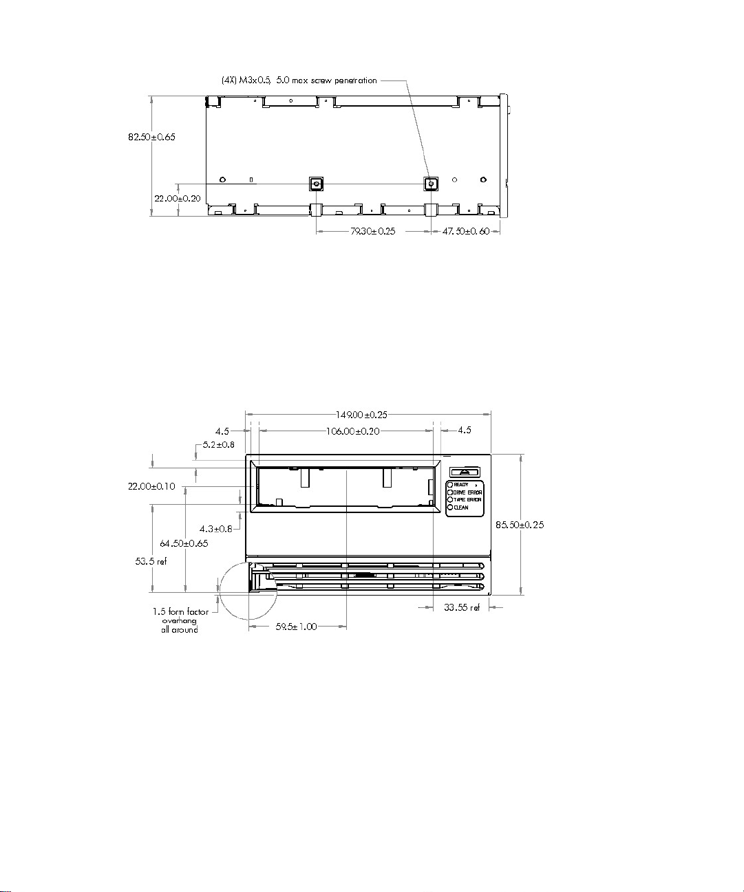
Figure 1-2 Side
With Fiber Channel, the connector stands out at the back of the drive:
Figure 1-3 Fibre Channel connect or
[No drawing available as of November 30, 2004]
Figure 1-4 Front
11
Page 12

Figure 1-5 Rear View—SCSI
Figure 1-6 Rear view—Fibre Channel
[No drawing available as of November 30, 2004]
Product weight
Internal* 2.239 kg (4.94 lb)
External 5.572 kg (12.28 lb)
*including front panel and ESD bag but excluding rails
Drive orientation
An HP Ultrium drive will operate in the 0°, –90° and +90° when viewed from the front panel.
In addition, in the 0° axis, the drive will operate with +20°nose-up tilt.
Physical specifica tion12
Page 13

3 Electr ical requirements
PSU requirements
Internal and rack-mounted drives
The drives are specified to operate at 5V±5% and 12V±10%. Any PSU used to power the
drive mu st be capable of providing 5V nominal (w hen the drive pulls 5A on the 5V rail) and
12V nominal (when the drive pulls 2A on the 12V rail). HP recommends a 10% buffer when
selecting a power supply source capable of delivering the amperage and power required.
SCSI Drives FC Drives
Specification 5V 12V 5V 12V
Maximum voltage 5.25V 13.2V 5.25V 13.2V
Minimum voltage 4.75V 10.8V 4.75V 10.8V
Maximum steady-state current 4.75*A 1.0A 4.75*A 1.0A
Maximum transient current 4.75*A 2.0A 4.75*A 2.0A
Maximum steady-state power 22.5W 12W 17.5W
Maximum transient power 22.5W 24W 22.5W 24W
Maximum noise/ripple 150 mVpp 150 mVpp 150 mVpp 150 mVpp
12W
* The current values are calculated based on constant power and minimum power supply voltage.
Power consumption
Power Requirements <40W 100–240 VAC 50/60 Hz 0.8A max.
5V DC 3.0A typ ical (4.5A max.)
12V DC 0.8A typical (2.0A max.)
Activity Average Peak Average
Idle
Load
Write
Internal Drives External Drives
SCSI Drives FC Drives
15.8W 15.8W TBD
18.1W 32.3W TBD
30.2W 35.3W TBD
13
Page 14

SCSI Drives FC Drives
Activity Average Peak Average
Read
Reposition/Rewind
Unload
24.3W 30.8W TBD
24.4W 31.6W TBD
16.8W 28.2W TBD
Electrical requirements14
Page 15

4 Electromagnetic compatibility
NOTE: The EMC performance of internal storage produ c ts depends on the characteristics of
the system i n whic h the pr oduct is inst alled. HP has tested pr oduc ts installed in netw ork sto r age
system enclosures and in external desktop enclosures to verify EMC performance against the
regulatory standards in force at the time of introduction.
ITE emissions
Standards
Parameter International European Economic Area
Radiated and conducted CISPR 22:1997
+ Amendment 1:2000
+ Amendment 2:2002
FCC CFR 47 Part 15, referencing
ANSI C63.4-2003 (U .S.A. only)
Harmonic current IEC 61000-3-2: 2000 EN 61000-3-2:2000
Voltage fluctuations and flicker IEC 61000-3-3:1994
+ Amendment 1:2001
EN 55022:1998
+ /A1:2000
+ /A2:2003
EN 61000-3-3:1995
+ /A1:2001
ITE immunities
Parameter International European Economic Area
Generally CISPR 24:1997
Electrostatic discharge IEC 61000-4-2:1995 EN 61000-4-2:1995
Radiated RF electromagnetic field IEC 61000-4-3:1995 EN 61000-4-3:1996
Electrical fast transient/Burst IEC 61000-4-4:1995 EN 61000-4-4:1995
Surge IEC 61000-4-5:1995 EN 61000- 4-5:1995
Conducted disturb ances by RF fields IEC 61000-4-6:1996 E N 61000-4-6:1996
Power frequency magnetic field IEC 61000-4 - 8:1993 EN 61000- 4-8:1993
Voltage dips, interruptions & varia tions IEC 61000-4- 11:1994 EN 61000-4-1 1:1994
+ Amendment 1:2001
+ Amendment 2:2002
referencing the following:
Standards
EN 55024:1998
+ /A1:2001
+ /A2:2003
referencing the following:
15
Page 16

DC magnetic field interference
• IATA Dangerous Goods Regulations, 30th Editio n, 1989-01-01
• U.S. CFR 49, paragraph 173.1020, revision date: 1983-11-01
Electromagnetic compatibility16
Page 17

5Environmental
Climatics
These apply to the mechanism unless otherwise noted. For the environmental specification of
media, see Chapter 7, “Media”.
Operating
Parameter Specification
Operating temperature with media at 6 cfm airflow: 10°C to 35°C (50°F to 95°F)
at 8 cfm airflow: 10°C to 40°C (50°F to 104°F)
Maximum operati n g t emperature rise 10°C/hr (50°F/hr)
Operating non-condensing humidity 20% to 80% RH
Maximum operating humidity rise <30%/hr
Maximum wet bulb temperature 26°C (79°F)
Operating altitude 0 to 4 km (0 to 13,000 ft)
Non-operating
Parameter Specification
Non-operating temperature -40°C to 66°C (-40°F to 151°F)
Maximum non-operating temperature rise 20°C/hr (68°F/hr)
Non-operating humidity 10% to 95% RH
Non-opera t i n g humidity rise 30%/hr
Non-operating altitude 0 to 15.25 km (0 to 50,000 ft)
General
Parameter Specification
Suspended particle density <200 µg/m
3
17
Page 18

Dynamics
Parameter Specification
Operating sine vibration 0.31G p k 5– 500 Hz @ 1 octave/min with 15 min dwell at peak
Operating random vibration 0.31G rms 5–500 Hz 0.000194 g
Operating shock 5G 3 ms half-sin e (no performance change)
Non-operating sine vibration 1.0G pk 5–500 Hz @ 1 octave/min with 5 min dwell at peak
Non-operating random vibration 2.41G rms 5–500 Hz
Non-operating shock 90G 3 ms half-sine (no damage)
Transportation sine vibration 0.5G pk 5–200–5 Hz @ 1 oct ave/min with 5 min dwell at peak
Transportation random vibration 1.47G rms 5–200 Hz
Package drop 0.91m (36 in)
Noise
resonance
2
/Hz
2G 11 ms half-sine (no performance change)
8G 11 ms half-sine (no data loss)
Pulse rate: 0.1 Hz
resonance
30G 26 ms trapezoidal (no damag e)
resonance
Airflow
Environmental18
Parameter Specification
Operating acoustic noise <5.0 bel sound power
HP Ultrium drives require forced airflow from front to back.
Parameter Specification
0.23 m
3
/min (6 cu ft/min) at 35ºC ambient operation, rising to
3
/min (8 cu ft/min) for up to 40ºC ambient operation
Airflow (operating and non-operating ) 0.17 m
Page 19

6Safety
Safety regulatory standards
Agency Referenced Standard
Underwriters Laboratories (UL)
Canadian S tan dards Association (CSA)
CE and TÜV
CB Report and Certi fi cate
Required agency approvals
Agency National Standard
NOM-1-NYCE
GOSH
VCCI
C-Tick
RRL
BSMI
Product Safety: NOM-0190SCFI-1998
Product Safety: GOST R 50377
EMC: GOST R 51318.22-99 & GOST R 50839=2000
Acoustic Report: GOST 26329-84
EMC: CISP R 22:1997
EM C: AS/NZS 3548 (EN 55022, CISPR22)
MIC No. 1996-18 (EN 55022)
CNS 13438
UL 60951 First Edition
CSA 22.2 60950-1-03
EN 60950-1:2001, including all amendments
IEC 60950-1:2001, including all amendments
IEC 60950-1:2001, inc luding all amendments (including
all National Deviations)
Transceivers
The Fibre Optic transceivers used in FC products are Class 1 Laser components and comply
with US FDA regulations.
These components are certif ied to meet the Class 1 e ye saf ety req uir ements of EN (IEC) 6 0825
and the electrical safety requirements of EN (IEC) 60950.
19
Page 20

7Media
Specification
HP Product Number Format Capacity* Notes
C7973A U3 800 GB Read and write
C7973W U3 WORM 800 GB Write on ce, read many times
C7972A U2 400 GB Read and write
C7971A U1 200 GB Read-only in Gen 3 drives
*Capacities at 2:1 data compression. The actual capacity depends on the compression ratio of the data. This is
typically 2:1 but can be anywhere between 1:1 and 110:1.
Tape Base film: 6 µm (Poly-Ethylene-Naphthalate) PEN
Tape length used for data: 580m 580m 648m
Tape dimensional stability: 1200 ppm 1200 ppm 1200 ppm
Maximum tape speed: 5.5 m/s 7.29 m/s 7.29 m/s
Cartridge Width: 105.4±0.30 mm 105.4±0.30 mm 105.4±0.30 mm
Recording layout Track pitch: 27 .5 µm 20.17 µm 14.3 µm
Ultrium 1 Ultrium 2 Ultrium 3
Tape length: 609m 609m 680m
Tape width: 12.65 mm 12.65 mm 12.65 mm
Tape thickness: 8.9±0.3 µm 8.9±0.3 µm 8.0±0.3 µm
Rewind speed: 4.1 m/s 7.00 m/s 7.00 m/s
Durability: 1,000,000 passes 1,000,000 passes 1,000,000 passes
Depth: 102.0±0.30 mm 102.0±0.30 mm 102.0±0.30 mm
Height: 21.5±0.25 mm 21.5±0.25 mm 21.5±0.25 mm
Weight: 0.220 kg 0.220 kg 0.220 kg
Track de ns ity (TPI): 768 1024 1773
Data tracks: 384 512 704
Data channels: 8816
Number of wraps: 48 64 44
Number of bands: 444
Bit density: 4.88 kb/mm 7.32 kb/mm 9.57 kb/mm
Media20
Page 21

Environmental specifications (media)
Operating
Parameter Specification
Ambient Temperature 10°C to 45°C (50°F to 113°F)
Relative Humidity (non-condensing) 10% to 80%
Maximum Wet Bulb Temperature 26°C (7 8.8°F)
Storag e (day-to-day)
Parameter Specification
Ambient Temperature 16°C to 35°C (60°F to 95°F)
Relative Humidity (non-condensing) 20% to 80%
Maximum Wet Bulb Temperat ure 26°C (78.8°F)
Storage (transportation)
Parameter Specification
Ambient Temperature -23°C to 49°C (-9.4°F to 102°F)
Relative Humidity (non-condensing) 5% to 80%
Maximum Wet Bulb Temperat ure 26°C (78.8°F)
Storage (archival)
Cartridges should be stored in plastic containers, preferably on their sides.
Parameter Specification
Ambient Temperature 16°C to 25°C (60°F to 77°F)
Relative Humidity (non-condensing) 10% to 50%
Maximum Wet Bulb Temperat ure 26°C (78.8°F)
Archive Life 30 years
LTO-Cartridge Memory (EEPR OM)
LTO Cartridge Memory (LTO-CM) is EEPROM memory that is embedded in every LTO Ultrium
tape cartridge. It is non-volatile and is contactless in that it is read by RF coupling rather than
electrical contact.
21
Page 22

Interface specification
• Contactless, passive RF interface using a proximity inductive coupling with a range in the
order of millimeters.
• P ower to the transponder is coupled thr o ugh the interface.
• The range depends on implementation (10 to 20 mm is the maximum). The best error rate
performance will occur at short distances.
• The memory can be read from below (by a drive) or from the front (in libraries).
• 32 kilobits (4 kilobytes)
• Organized as 12 8 x 32 byte block s
• >500K write cycles, 20 year data retention life
• Write size is word wide (2 bytes) or block wide (32 bytes)
• The transfer- rate performance of the cartridge memory is as follows:
• Reads:
• Writes:
•
32 byte read: ~ 5.8 ms 32 byte write: ~ 15.8 m s
2 byte: ~20 Kb/s 32 byte: ~70 Kb/s 4 KB: ~0.5s
2 byte: ~1.4 Kb/s 32 byte: ~18.5 Kb/s 4 KB: ~1.8s
Further information
• For general information about LTO-CM, see “LTO Cartridge Memory” in Chapter 5,
“Cartridges” in Background to Ultrium Drives, Volume 6 of the Ultrium Technical Manual.
• For suggestions of how to make use of cartridge memory in libraries, see “LTO Cartridge
Memory (L TO-CM)” in Chapter 5, “Supporting Ultrium Feature s” in Soft ware Integration,
Volume 2 of the Ultrium Technical Manual.
Media22
Page 23

8 Ultrium format standard
Compatibility
HP Gen 3 Ultrium drives are specified to interchange data cartridges with other tape drives
that comply to the LTO U-18, U-28, and U-316 specification documents:
Capacity (2:1 compression) Format Write Read
800 GB WORM Ultrium-3 Yes Yes
800 GB (680m) Ultrium-3 Yes Yes
400 GB (580m) Ultrium- 2 Yes Yes
200 GB (580m) Ultrium-1 No Yes
100 GB (290m) Ultrium-1 No Yes
This specif i cation is only applicable when:
• Cartridges carry the Ultrium logo.
• Cartridges are not damaged or faulty.
• Cartridges are read on a drive in good operating condition, and have been written on a
logo-certified drive that is in good condition.
• The environmental conditions (including DC voltage supplies) ar e w ithin the s pec if i ed limits .
NOTE: HP Gen 3 Ultrium drives do not support 10 GB and 30 GB cartridges. HP
recommends the use of the
logically for test purposes.
SET CAPACITY SCSI command to shorten standard cartridges
Future compatibility
In future, HP Ultrium dri ves will always be capable of r eading and writing tapes from the
curre nt generatio n and one generation bef ore , and reading tapes fr om two gener ations befo re.
HP Ultrium drives will always maintain write and read compatibility with other manufacturers’
Ultrium drives and tapes that meet the LTO Ultrium format specification.
23
Page 24

9Reliability
Description Specification
MTBF (100% duty cycle) 250,000 hours
Load/unload life 100,000 swaps
MSBF (automation swaps) 100,000 swaps
Head life (typical) 60,000 hours
Media durability 1,000,000 passes
Maximum cartridge uses 20,000 threads
Backup failure rate <0.1%
Restore failure rate <0.001%
Interchange failure rate <0.1%
Uncorrectable error rate
Undetected error rate
Tape pulling life (5 years at 100% duty cyc le) 43,800 hours
1 in 10
1 in 10
17
27
bits
bits
Reliability24
Page 25

10 Performance specification
Transfer r ates
SCSI FC
Sustained transfer rate Native: 80 MB/s 80 MB/s
Compressed (2:1): 160 MB/s 160 MB/s
Burst transfer rate Ultra3 SCSI wide: 320 MB/s
Ultra3 FC: 2 GB/s: class 3
ATS data rate range (3:1) 27–80 MB/s (U3)
10–30 MB/s (U2)
6.6–20 MB/s (U1)
The bandwidth of the data compression engine determines the drive’s streaming capabilities
based on the compressio n ratio of the data it is handling as follows:
Compression Engine Bandwidth: 120 MB/s
Maximum Streaming Compression Ratio: 3:1
The drive will match the throughput of any host up to the maximum native transfer rate
multiplied by the cur ren t compr ession r atio . Ther e w ill not be an y performance penalty fo r hosts
that are slower than the maximum. This capability is accomplished with a 64 MB buffer and
the Adaptive Tape Speed (ATS) algorithm.
Speeds
Data compression
The compression engine uses an enhanced algorithm based on ALDC where data expansion
due to redundant data is minimized to <5%. This is achieved by having two compression
schemes (normal and pass-through) with the ability to switch dynamically between them.
It is possible to force the drive to use Scheme 2 (pass-through mode) of the LTO-DC algorithm
using the Data Compression mode page or the SDCA parameter in the Sequential Access
Mode Page.
Maximum tape speed 7.00 m/s
Tape read/write speed 5.32 m/s (Ultrium-3), 5.50 m/s (Ultrium-1/2)
Tape rewind speed 7.00 m/s
25
Page 26

Timings
Capacity full backup times
The following table shows approximate backup times for the available tape cartridges:
Cartridge Time
800 GB Ultrium 3
400 GB Ul trium 2
200 GB Ultrium 1
1 hr 30 min at a transfer rate >70 MB/s
1 hr 55 min
1 hr 55 min
Load/unload times
The load and unload times are as follows:
SCSI FC
Typical load time to BOT, ready to read or write <19s* <19s*
Unload time, excluding rewind <19s <19s
Automation eject (tape unthreaded) <1s <1s
* The unload time for WORM cartridges is greater, typically 22s
Access times (time to data)
Average access time fr om BOT 800 GB Ultrium 3: 52s
400 GB Ultrium 2: 46s
200 GB Ultrium 1: 46s
Maximum access time from BOT 800 GB Ultrium 1: 104s
400 GB Ultrium 2: 92s
200 GB Ultrium 1: 92s
Other times
Parameter Time
Mean reposition time 2.5s
Turn-around time at end of wrap 1.5s max.
Time to rewind EOT–BOT at 7.0 m/s 98s (U3), 88s (U1/2)
Time to rewind MOT—BOT at 7.0 m/s 49s (U3), 44s (U1/2)
Cleaning tim e with a cleaning cartridge <180s
Performance specification26
Time
Page 27

11 Automation Control Interface
Specification
Physical interface
• RS-422, Drive Sense, Library Sense, Reset and Attention signals
• A default of 9600 baud at power-on, after a tape drive reset and after an ACI reset. After
that, the library can configure the tape drive to use other baud rates (19200, 38400,
57600 and 115200 baud for HP Ultrium dri ves) using the Set Baud Rate command.
• 1 start bit, 8 data bits, 2 stop bits, no parity
Protocol
• Binary data packets, including checksum, packet length, status, sequence number,
• XON/XOFF flow control
• Positive or negative acknowledgement of transmission
• Constant polling not necessary— the drive returns status upon completion of each
command
ACI command set
The following ACI commands are supported on HP Ultrium drives:
Mandatory Commands Optional Commands SCSI Surrogate Commands
00h Get Drive Info 40h Send SCSI Command 70h Configure SCSI Surrogate
01h Load 42h Send Firmware Image 71h Get SCSI CDB
02h Unload 43h Get Firmware Segment 72h Get SCSI Data
03h Get Drive Status 49h Get Buffer Size 73h Send SCSI Data
04h Set Drive Configuration 4Ah Send Firm ware Segment 74h Send SCSI Status
05h Get Drive Configuration 4Bh Set Time
06h Reset 4Ch Get Time
07h Set Baud Rate
08h No Op
09h Get Error Info
0Ah Acknowledge Attention
27
Page 28

Automation Control Interface28
Page 29

Index
A
access time 26
ACI 27
agency approvals 19
airflow 18
altitude 17
ANSI 5
archival storage
environment 21
automation control interface 27
B
backup times 26
bandwidth 25
C
climatics 17
CM 9, 21
compatibility 23
compression 25
compression format 9
D
data compression 25
dimensions, drive 10
documents, related 5
drive orientation 12
dynamics 17
E
electrical requirements 13
electromagnetic compatibility
15
emissions 15
environmental specifications
17
error rates 24
F
features 9
fibre channel connector 11
format 9
format standard 23
future compatibility 23
H
humidity
drives 17
media 21
I
immunities 15
interfaces 9
L
library interface 9
life of drive 24
load/unload times 26
LTO-cartridge memory 21
M
magnetic field interference 15
media specification 20
MTBF 24
N
noise 18
O
orientation 12
P
performance specification 25
physical specification 10
power consumption 13
PSU requirements 13
R
read-while-write 9
reliability 24
rewind times 26
S
safety regulatory standards 19
SCSI 5
shock 17
speed of recording 9
suspended particle density 17
T
temperature
drives 17
media 21
times
access 26
capacity full backup 26
load/unload 26
rewind 26
turn-around 26
transfer rates 25
transportation of media 21
turn-around times 26
U
Ultrium format standard 23
V
vibration 17
W
weight, drive 12
wet bulb temperature
drives 17
media 21
Index
Index 29
Page 30

Index30
 Loading...