

Page 1

HP ThinPro 4.3
Administrator's Guide
Document Part Number: 727357-002
Edition: Second Edition: May 2013, First Edition: February 2013
Page 2

© Copyright 2013 Hewlett-Packard
Development Company, L.P.
Microsoft and Windows are U.S. registered
trademarks of Microsoft Corporation.
Confidential computer software. Valid
license from HP required for possession,
use or copying. Consistent with FAR 12.211
and 12.212, Commercial Computer
Software, Computer Software
Documentation, and Technical Data for
Commercial Items are licensed to the U.S.
Government under vendor's standard
commercial license.
The information contained herein is subject
to change without notice. The only
warranties for HP products and services are
set forth in the express warranty statements
accompanying such products and services.
Nothing herein should be construed as
constituting an additional warranty. HP shall
not be liable for technical or editorial errors
or omissions contained herein.
Page 3

Table of contents
1 Introduction ....................................................................................................................................................... 1
Using HP ThinPro ................................................................................................................................. 1
Logging in to Administrative Mode ....................................................................................... 1
Identifying the taskbar components ..................................................................................... 2
2 Setup and installation ........................................................................................................................................ 3
Easy Tools Wizard ............................................................................................................................... 3
Installation ............................................................................................................................................ 3
3 Connections ...................................................................................................................................................... 4
Connect ................................................................................................................................................ 5
Disconnect ............................................................................................................................................ 5
General settings ................................................................................................................................... 5
Citrix ICA .............................................................................................................................. 5
Web browser ........................................................................................................................ 8
RDP ..................................................................................................................................... 9
Add ....................................................................................................................................................... 9
Citrix ................................................................................................................................... 10
Citrix connection management features ............................................................ 10
Citrix receiver features ...................................................................................... 10
HDX MediaStream support matrix .................................................... 11
Citrix connection support matrix ........................................................................ 12
Creating a Citrix connection .............................................................................. 12
RDP ................................................................................................................................... 13
RDP client connections ..................................................................................... 13
Creating an RDP7 connection ........................................................................... 13
HP TeemTalk ..................................................................................................................... 16
Adding an HP TeemTalk connection using the HP TeemTalk creation
wizard ................................................................................................................ 17
Adding an HP TeemTalk connection manually ................................................. 18
Web browser ...................................................................................................................... 19
RGS ................................................................................................................................... 19
VMware Horizon View ....................................................................................................... 20
Setting up a VMware Horizon View connection ................................................ 20
Logging in to the VMware Horizon View Manager server ................................. 21
Using Kiosk Mode with VMware Horizon View ................................................. 21
iii
Page 4

Using Multimedia Redirection with VMware Horizon View ................................ 22
Using multi-monitor sessions with VMware Horizon View ................................ 22
Using keyboard shortcuts with VMware Horizon View ...................................... 22
Using device redirection with VMware Horizon View ........................................ 22
Using USB redirection with VMware Horizon View .......................... 22
Using mass storage redirection with VMware Horizon View ............ 22
Using printer redirection with VMware Horizon View ........................ 22
Using audio redirection with VMware Horizon View ......................... 23
Using smart card redirection with VMware Horizon View ................. 23
Advanced VMware Horizon View options ......................................................... 24
Using advanced command line arguments ...................................... 24
Starting a desktop connection using PCoIP instead of RDP ............ 24
XDMCP .............................................................................................................................. 24
SSH ................................................................................................................................... 25
Telnet ................................................................................................................................. 27
Custom .............................................................................................................................. 27
Copy ................................................................................................................................................... 28
Delete ................................................................................................................................................. 28
Edit ..................................................................................................................................................... 28
User View ........................................................................................................................................... 28
4 Control Panel .................................................................................................................................................. 29
Peripherals ......................................................................................................................................... 29
Client aggregation .............................................................................................................. 30
Client aggregation overview .............................................................................. 30
Configuring client aggregation .......................................................................... 32
Configuring the aggregation clients .................................................. 32
Configuring the aggregation server .................................................. 32
Disabling client aggregation .............................................................................. 34
Display preferences ........................................................................................................... 35
Adding a profile ................................................................................................. 35
Editing a profile ................................................................................................. 36
Deleting a profile ............................................................................................... 36
Keyboard layout ................................................................................................................. 36
Mouse ................................................................................................................................ 36
Printers .............................................................................................................................. 36
SCIM input method setup .................................................................................................. 37
Sound ................................................................................................................................ 37
ThinPrint ............................................................................................................................ 37
Touch screen ..................................................................................................................... 37
Redirecting USB devices ................................................................................................... 38
iv
Page 5

Setup .................................................................................................................................................. 38
Background manager ........................................................................................................ 38
Date and time .................................................................................................................... 39
Language ........................................................................................................................... 40
Network .............................................................................................................................. 40
Screensaver ....................................................................................................................... 42
Security .............................................................................................................................. 42
HP ThinPro configuration ................................................................................................... 43
Setting connections and Control Panel user permissions ................................. 43
Setting user desktop and system options ......................................................... 43
Management ...................................................................................................................................... 43
AD/DDNS Manager ........................................................................................................... 44
Easy Deploy ....................................................................................................................... 44
Easy Config ....................................................................................................................... 44
Easy Update ...................................................................................................................... 44
Factory reset ...................................................................................................................... 45
HP Automatic Update ........................................................................................................ 45
HPDM Agent ...................................................................................................................... 45
SSHD Manager .................................................................................................................. 45
ThinState ........................................................................................................................... 46
Manage the HP ThinPro image ......................................................................... 46
Capture HP ThinPro image to an FTP server ................................... 46
Deploy HP ThinPro image from a remote site .................................. 46
Capture HP ThinPro image to a bootable USB flash drive ............... 47
Deploy HP ThinPro image from a bootable USB flash drive ............ 48
Manage the HP ThinPro configuration .............................................................. 48
Save the HP ThinPro configuration on an FTP server ..................... 48
Restore an HP ThinPro configuration from a remote server ............ 48
Capture an HP ThinPro configuration to a USB drive ...................... 49
Restore an HP ThinPro configuration from a USB key ..................... 49
VNC Shadow ..................................................................................................................... 49
Advanced ........................................................................................................................................... 50
CDA mode ......................................................................................................................... 50
Certificates ......................................................................................................................... 51
Importing certificates ......................................................................................... 51
Removing certificates ........................................................................................ 51
Viewing certificates ........................................................................................... 52
VMware Horizon View HTTPS and certificate management requirements ....... 52
DHCP Option Manager ...................................................................................................... 54
Text editor .......................................................................................................................... 54
X Terminal ......................................................................................................................... 54
v
Page 6

Keyboard shortcuts ............................................................................................................ 54
5 System Information ......................................................................................................................................... 56
General ............................................................................................................................................... 56
Network .............................................................................................................................................. 57
Net tools ............................................................................................................................................. 57
Software information .......................................................................................................................... 58
System logs ........................................................................................................................................ 58
Index ................................................................................................................................................................... 59
vi
Page 7
1 Introduction
The HP ThinPro operating system reinvents user interface simplicity with a single console interface
for dashboard access to all user and administrative touch points. A default Connection Manager view
integrates traditional connection types with the latest Virtual Desktop Infrastructure (VDI) broker
connections with shared access to settings. Administrators are only one click away from the Easy
Config setup wizard, Control Panel, and System Information layers.
Using HP ThinPro
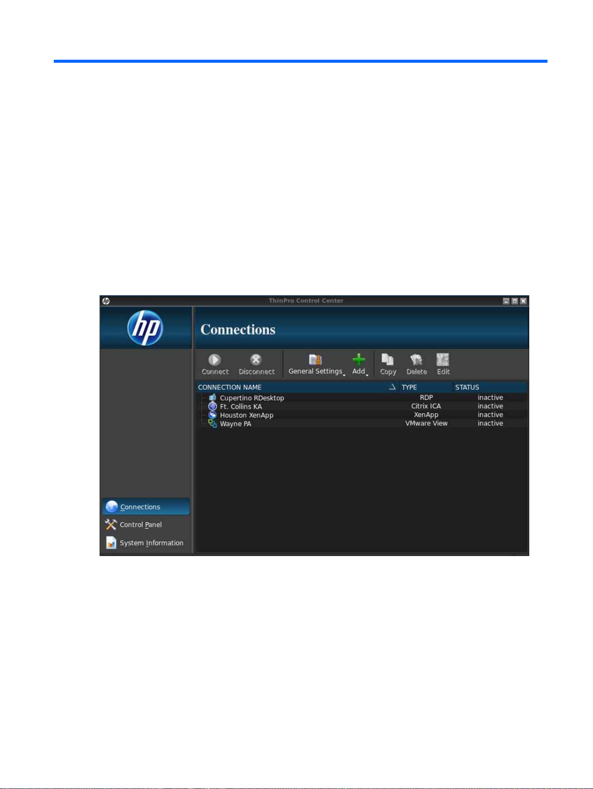
The HP ThinPro interface is displayed by default when you turn on the thin client. The desktop
includes a volume icon, a clock, and a taskbar that provides access to open applications. Click on
ThinPro Control Center in the left side of the taskbar to open and close the HP ThinPro interface.
Figure 1-1 HP ThinPro Control Center
HP ThinPro allows you to launch and manage host and remote application connections. Set up
connections and connection types that are visible in User Mode while logged in as an administrator.
An administrator can also restrict users from deleting or creating connections.
Logging in to Administrative Mode
You must log in with administrator permissions to access all components of the HP ThinPro interface.
When the thin client is in Administrative Mode, the following changes occur:
The top section of the control center changes from blue to red.
●
The title adds the text “Administrative Mode”.
●
By default, HP ThinPro opens in User Mode. To switch to Administrative Mode:
Using HP ThinPro 1
Page 8
1. Click the HP logo in the bottom left of the screen.
—or—
Position your cursor over the screen background and right-click.
2. Select Administrator/User Mode Switch.
3. In the Switch to Administration Mode box, under Administrative password, type a password and
click OK.
NOTE: If you are logging in to Administrative Mode for the first time, retype your password
before clicking OK.
You can also switch modes as follows:
1. Press Ctrl+Alt+Shift+S, select Switch to Administration Mode, and click OK.
2. Type the administrative password in the field and click OK.
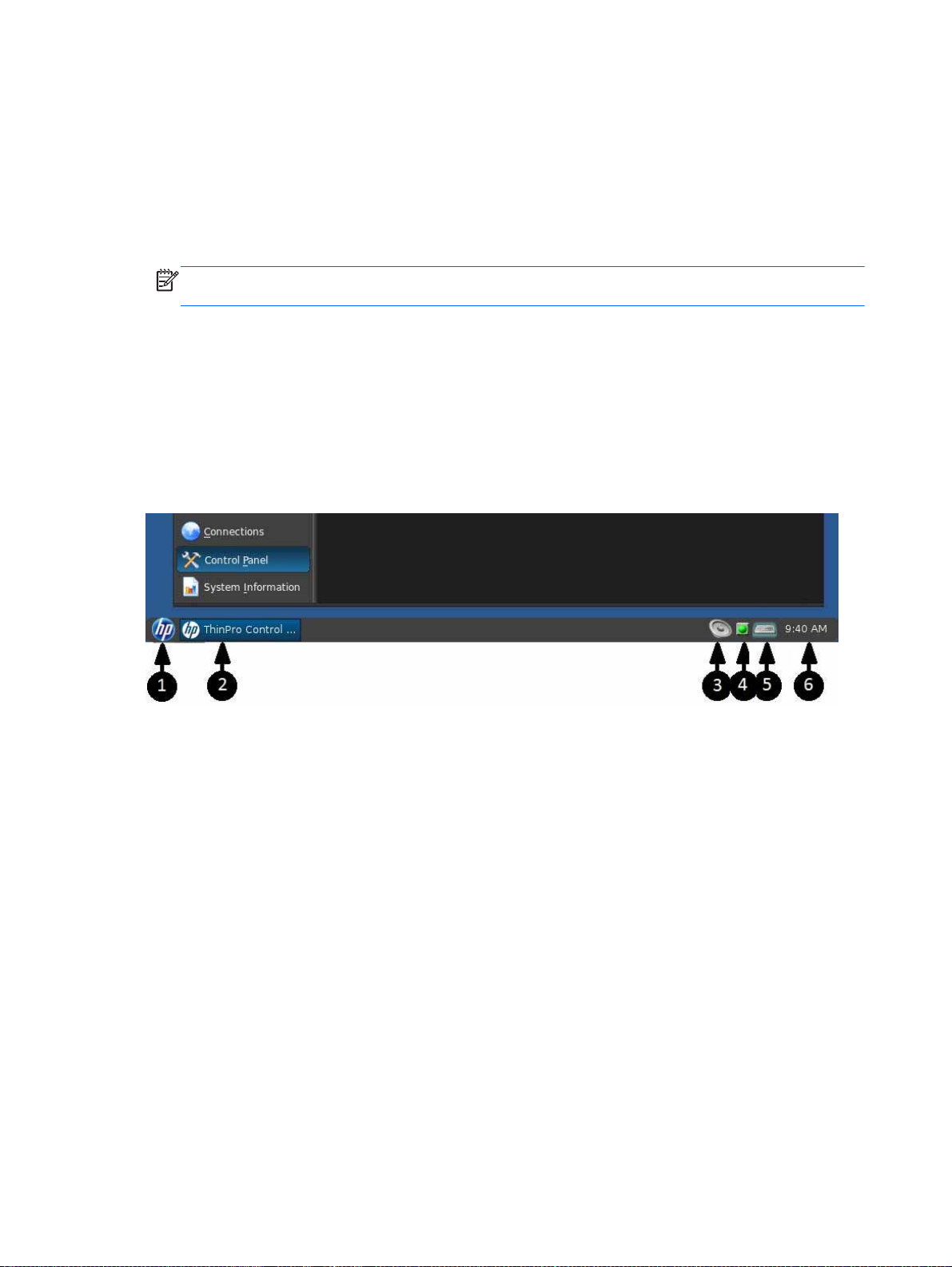
Identifying the taskbar components
The taskbar is a bar across the bottom of the screen that contains several controls:
Figure 1-2 HP ThinPro taskbar
1. HP button—Allows access to the basic functionality of the HP ThinPro operating system, such
as access to the control center and the logout, reboot, and power-off functions.
2. Window tasks—Each active window has an icon displayed in this area.
3. Volume control—Displays a sound control dialog that allows you to change the sound volume for
the thin client.
4. Network icon—Displays information about the active network connections.
5. Virtual keyboard—Displays a software keyboard. Input from the virtual keyboard is redirected to
the current focus window. The virtual keyboard responds to both keyboard events and mouse or
touchscreen clicks. You can change the layout of the virtual keyboard without changing the
overall client keyboard layout; for example, you could use a French virtual keyboard just long
enough to type a few accented characters before closing it and returning to the normal keyboard
layout. The virtual keyboard's layout is active only while its window is open.
6. Clock display—Displays the time according to the thin client's clock. Hovering the cursor over
the clock display shows a tooltip containing the current date.
2 Chapter 1 Introduction
Page 9

2 Setup and installation
HP ThinPro has a wizard-driven interface to simplify the configuration process of a thin client.
Easy Tools Wizard
The Easy Tools Wizard simplifies the configuration and maintenance processes for HP ThinPro. The
wizard opens automatically the first time you turn on your thin client. To start the wizard after the
initial setup, click the HP icon in the left pane.
The Easy Tools Wizard has two main components: Easy Update and Easy Config. Easy Update
allows you to keep the HP ThinPro image up-to-date with new images, service packs, or additional
packages. Easy Config assists you in setting up your HP ThinPro configuration. Both Easy Update
and Easy Config are available from the Control Panel > Management tab.
The Easy Tools thin client management suite is documented in the
which can be found at http://www.hp.com/support.
Guide
Installation
Once you have set up and configured a thin client, copy that image or configuration and deploy it to
other thin clients of identical model and hardware using HP ThinState. See
for more information.
HP Easy Tools Administrator’s
ThinState on page 46
Easy Tools Wizard 3
Page 10
3 Connections
HP ThinPro allows you to access and manage remote connections. To access all HP ThinPro
functionality, you must log in as an Administrator. As a User, you can only run connections and have
limited access to HP ThinPro functionality.
The HP ThinPro display, when configured, lists all server and/or application connections assigned to
the user currently logged on to the terminal. For each connection, the display shows the name, type,
and status of the connection.
NOTE: Double-click any displayed connection to activate that connection.
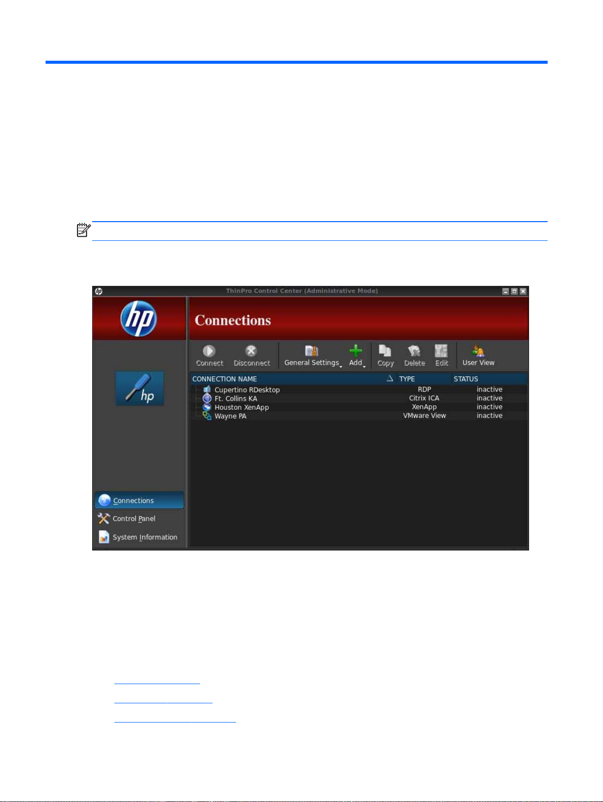
In Administrative Mode, you can configure and assign connections by clicking Connections.
Figure 3-1 HP ThinPro Control Center—Administrative Mode
The Connections window lists all connections that you can assign to users. You can add, edit, and
delete connections from this window.
Connection Name: Displays the name of the connection. You cannot change the connection
●
name from this column.
Type: Displays the type of connection. You cannot change the connection type from this column.
●
Status: Displays the status, active or inactive, of the connection.
●
There are eight buttons across the top of the connection list:
Connect on page 5: Click to start a selected connection.
●
Disconnect on page 5: Click to disconnect a selected connection.
●
General settings on page 5: Click to manage connection settings.
●
4 Chapter 3 Connections
Page 11

Add on page 9: Click to create a new connection and add it to the list of available
●
connections.
Copy on page 28: Click to copy a connection and add it to the list of available connections.
●
Delete on page 28: Click to delete the selected connection. The connection is deleted from the
●
lists of connections assigned to all users, not just the user currently logged on to the terminal.
Edit on page 28: Click to edit the selected connection.
●
User View on page 28: Click to edit connections visible in User Mode.
●
Connect
To open a connection, select a selection under Connection Name that has a Status of inactive and
click Connect.
Disconnect
To close a connection, select a selection under Connection Name that has a Status of active and
click Disconnect.
General settings
General settings are shared by all connections of a given connection type. Three types of
connections are available: Citrix ICA, Web Browser, and RDP. The options for each connection type
are listed below:
Citrix ICA
The options available for a Citrix ICA connection are listed in the following tables.
Table 3-1 Citrix ICA connection options
Option Description
Enable HDX MediaStream Whenever possible, HDX MediaStream leverages the
Enable Windows Alert Sound Enable the Windows alert sound.
ICA Acceleration (LAN Only) Enable ICA Acceleration.
Allow Backing Store Allow for backing store.
Use Server Redraw Use the server's redraw functionality.
Disable Info Box Before Connecting
Use Asynchronous COM-port Polling Use asynchronous polling of the COM port.
Allow Smart Card Logon Use a client-connected Smart Card for logon authentication.
Enable Off Screen Surface
processing power of the thin client to render the multimedia
content. On the datacenter side, the compressed multimedia
information is sent directly to the thin client in its native
format. The experience will vary based on the processing
power and multimedia capability of the thin client.
Do not display the information box displayed before a
connection is completed.
Directs the ICA Client to draw screen updates to an inmemory bitmap rather than to the screen, improving
bandwidth efficiency.
Connect 5
Page 12

Table 3-1 Citrix ICA connection options (continued)
Option Description
Enable Session Sharing Enable the session to be shared.
Enable Auto Reconnect Enable automatic reconnection of dropped connections.
Enable UseLocalIM Uses the local input method to interpret keyboard input. This
is supported only for European languages.
Use EUKS Number Controls use of Extended Unicode Keyboard Support on
Windows servers:
0=no EUKS
1=EUKS used as fallback
2=use EUKS whenever possible
Minimum Bitmap Cache Size Minimize the bitmap cache size.
Use Data Compression Use data compression for this connection.
Enable Middle Button Paste
Use Disk Cache for Bitmaps Use a disk cache for connection bitmaps.
Sound
Speed Screen Valid options are: Auto, On, and Off.
Mouse Click Feedback Valid options are: Auto, On, and Off.
Enables a middle mouse button click to perform a paste
operation.
Specifies the sound quality to be used. Valid options are:
High Quality, Med Quality, and Low Quality.
Table 3-2 Citrix ICA connection local resources options
Option Description
Allow Audio Input Allow audio input from the thin client.
Auto Printer Creation Automatically create a printer.
Drive Mapping
Enable Drive Mapping Allows you to specify drive mappings to local paths.
Table 3-3 Citrix ICA connection window options
Option Description
Enable Seamless Window
Default Window Size
Default Window Colors
Default 256 Color Mapping
6 Chapter 3 Connections
Allows you to display a single window on the local ThinPro
desktop as if it were a native application.
Establish the default window size. Options are: Full Screen,
Fixed Size, Percentage of Screen Size.
Establish the default window colors. Options are: 16, 256,
16-bit, 24-bit, Automatic.
This option is only enabled if Default Window Colors is set to
256. Options are: Shared - Approximate Colors and Private Exact Colors.
Page 13

Table 3-4 Citrix ICA connection firewall options
Option Description
Proxy Proxy server settings.
Proxy Type
Proxy Address The IP address of the proxy server.
Proxy Port The port for connection to the proxy server.
Username The username to use for connection to the proxy server.
Password The password to use for connection to the proxy server.
Use Alternate Address for Firewall
Connection
Options are: None - direct, SOCKS, Secure - HTTPS, Use browser settings,
Automatically detect proxy.
The Citrix ICA Client will request the alternate address defined for the server when
contacting servers inside the firewall. The alternate address must be specified for
each server in a server farm.
Table 3-5 Citrix ICA connection server location options
Option Description
Default Protocol
TCP Address
HTTP Address
The default protocol for this connection. Options are: TCP/IP Browser, TCP/IP
HTTP Browser, SSL/TLS HTTPS Browser.
The TCP address of the Citrix server. The three buttons enable you to add, edit, or
delete entries from the list.
The http address of the Citrix server. The three buttons enable you to add, edit, or
delete entries from the list.
Table 3-6 Citrix ICA connection keyboard shortcuts options
Option Description
Handling of keyboard shortcuts
Stop Direct key handling
List of individual function keys and their mappings.
Specifies how function keys should be handled. Options are:
Translated, Direct in full screen desktops only, and Direct.
Not enabled when the option Handling of keyboard shortcuts
is set to Translated.
Only enabled when Handling of keyboard shortcuts is
Translated or Direct in full screen desktops only.
Table 3-7 Citrix session options
Option Description
The Auto Logout Delay box applies to Citrix servers using
multiple published resources. If applicable to your system,
use the Auto Logout Delay to set the number of seconds
Auto Logout Delay
between the closing of the last Xen published resource and
the time that a user automatically logs out and returns to the
initial login screen.
If you do not launch an application after the initial login, use
the Auto Logout Delay option to set the number of seconds
General settings 7
Page 14

Table 3-7 Citrix session options (continued)
Option Description
Auto Logout Delay with Single App
Web browser
that pass before a user automatically logs out and returns to
the initial login screen.
NOTE: Citrix processing delays may extend the auto-logout
processing time.
TIP: If desired, set the Auto Logout Delay value to less than
0. This ensures that ThinPro does not perform an auto-logout
The Auto Logout Delay with Single App applies to Citrix
servers using a single published application or desktop. If
applicable to your system, use the Auto Logout Delay with
Single App box to set the number of seconds between the
closing of a Xen published resource and the time that a user
automatically logs out and returns to the initial login screen.
NOTE: Citrix processing delays may extend the auto-logout
processing time.
TIP: If desired, set the Auto Logout Delay value to less
than 0. This ensures that ThinPro does not perform an autologout.
The configuration options for a web browser connection are:
Table 3-8 Web browser connection general options
Option Description
Web Browser preferences Pressing this button starts the web browser options dialog.
Allow connections to manage their own settings Allow the web browser to control the connection settings.
8 Chapter 3 Connections
Page 15

RDP
The configuration options for an RDP connection are:
Table 3-9 RDP connection general options
Option Description
Add
Send hostname as
Multimedia Redirection
Send your thin client's MAC address or hostname as the
hostname specified to the remote system.
Select 1 to enable multimedia redirection. Select 0 to disable
multimedia redirection.
The Add button is used to create new connections. When a new connection is created, you are
guided to set connection-specific options by a wizard interface. The wizard dialog boxes contain a
Previous and Next button which allows you to move forward and back through the wizard dialogs.
Each connection type wizard contains a dialog named Advanced that contains common settings for
all connection types. The following table describes the Advanced connection wizard settings:
Table 3-10 New connection advanced settings
Option Description
If the connection fails to start, attempt to start the fallback
Fallback Connection
Auto start priority
connection instead.
NOTE: This option is not available for the RGS or VMware
Horizon View connection types.
The autostart priority determines the ordering of connection
startup. 0 means the connection is disabled, with the other
values determining the startup ordering.
Valid options are: 0, 1, 2, 3, 4 and 5.
Auto reconnect Attempt to auto-reconnect if this connection is dropped.
Disable this option if your connection doesn’t need the
Wait for network before connecting
Show icon on desktop A desktop icon will be created for this connection.
Allow the user to launch this connection
Allow the user to edit this connection This connection can be modified by a non-administrator user.
network in order to start or if you don’t want to wait for
network to start the connection.
This connection can be launched by a non-administrative
user.
NOTE: The “allow the user” options are available only in the Administrative Mode.
You can create any of the following connection types:
Citrix on page 10
●
RDP on page 13
●
HP TeemTalk on page 16
●
Add 9
Page 16

Web browser on page 19
●
RGS on page 19
●
VMware Horizon View on page 20
●
XDMCP on page 24
●
SSH on page 25
●
Telnet on page 27
●
Custom on page 27
●
Citrix
A Citrix connection accesses the Citrix SBC (Server-Based Computing) and VDI (Virtual Desktop
Infrastructure) services.
Configure a Citrix remote connection with the connection wizard. If the default values do not meet
your requirements, use the extended options to complete the connection setup process.
Citrix connection management features
When using a Citrix connection, you can configure the client to automatically perform the following
functions:
Launch resources when only a single resource is published
●
Launch a specified resource
●
Launch a published desktop
●
Reconnect sessions on connection startup
●
Log off the connection after a specified timeout period
●
Launch published resources use the following configurable shortcuts:
●
Desktop icons
◦
Start menu icons
◦
Taskbar icons
◦
Citrix receiver features
Citrix receiver features include the following:
Latest version at the time of release:
●
12.1.5 for x86
◦
12.5 for ARM/SoC
◦
Window size and depth settings
●
Seamless window support
●
Sound quality settings
●
Low
◦
Medium
◦
10 Chapter 3 Connections
Page 17

High
◦
Disabled
◦
Static drive mapping
●
Dynamic drive mapping
●
USB redirection for XenDesktop and VDI-in-a-Box
●
Smart card virtual channel enablement
●
NOTE: This feature is equivalent to a smart card login/authentication when using direct, non-
PNAgent connections. With a PNAgent connection, smart card virtual channel enablement
enables or disables the smart card virtual channel but does not provide for initial connection
authentication. For a smart card authentication to XenApp and XenDesktop, use the provided
Web Browser connection instead of the Citrix connection and be sure to enable web access.
Printer mapping
●
Serial port mapping
●
HDX MediaStream (hardware-accelerated on most models)
●
HDX Flash Redirection (x86-only)
●
HDX Webcam Compression
●
HDX RealTime (MS Lync Optimization) (x86-only)
●
HDX MediaStream support matrix
Table 3-11 HDX MediaStream support matrix
Feature Support
Frame rate
Resolution
Video containers
Video codecs
24 fps
●
1080p
●
720p
●
WMV
●
AVI
●
MPG
●
MPEG
●
MOV
●
MP4
●
WMV2
●
WMV3 / VC-1
●
H.264 / AVC / MPEG-4 Part 10
●
MPEG-4 Part 2
●
H.263
●
DivX
●
Xvid
●
Add 11
Page 18

Table 3-11 HDX MediaStream support matrix (continued)
Feature Support
Audio codecs
Citrix connection support matrix
The following table describes the supported Citrix backends.
Table 3-12 Citrix connection support matrix
Backend
XenApp XenDesktop VDI-in-a-Box
Direct (legacy) 4.5 / 5 / 6 / 6.5
MPEG1
●
MP3
●
WMA
●
AAC
●
PCM
●
mpeg-audio
●
MLAW / ULAW
●
Access type
Creating a Citrix connection
1. Obtain the following Citrix server information:
Hostname
●
—or—
IP address
●
NOTE: If you are configuring a connection to a server on an HTTPS site, be sure to provide the
Fully Qualified Domain Name (FQDN) of the site and the local root certificate in the Citrix
certificate store.
2. In the HP ThinPro interface, log in as the administrator.
3. Under Connections, select Add > Citrix.
4. In the Configuration dialog box, fill in the following information:
Table 3-13 Citrix connection configurations
Option Description
Native (PNAgent) 4.5 / 5 / 6 / 6.5 4.5 / 5.5 / 5.6.5 5.x
Web browser 4.5 / 5 / 6 / 6.5 4.5 / 5.5 / 5.6.5 5.x
Name The connection name.
Server URL
12 Chapter 3 Connections
The Citrix server hostname or IP address. If you are configuring a connection
to a server on an HTTPS site, enter the FQDN for the site and the local root
certificate in the Citrix certificate store.
Page 19

Table 3-13 Citrix connection configurations (continued)
Option Description
Username The username to use for the connection.
Password The password to use for the connection.
Domain The domain to use for the connection.
Autostart resource The name of an autostart resource.
5. When completed, click Next.
6. In the Advanced dialog box, select the appropriate options:
Table 3-14 Citrix connection advanced configurations
Option Description
Fallback connection
Autostart priority
Wait for Network before connecting
Show icon on desktop Creates a desktop icon for this connection.
7. Click Finish to save your settings and close the wizard.
NOTE: To enable Citrix USB redirection, use the USB Manager utility. See Redirecting USB
devices on page 38 for instructions.
RDP
Microsoft Remote Desktop Protocol (RDP) enables Windows-based applications to communicate
over network connections. It is installed on all versions of Windows later than Windows NT.
RDP client connections
The RDP client is based on FreeRDP 1.0 and meets the following requirements for RDP 7.1:
Hardware-accelerated RemoteFX
●
Select a fallback connection. HP ThinPro attempts to start a fallback
connection when the original connection does not start.
Determines the connection startup order. 0 means the connection is disabled.
The other values determine the startup order. Valid options are: 0, 1, 2, 3, 4,
and 5.
Disable this option if your connection does not need the network to start or if
you do not want to wait for the network to start the connection.
MMR supported when connecting to Windows hosts with the Desktop Experience feature
●
enabled (Windows 7 or Windows Server 2008 R2)
USBR supported when connecting to Windows 7 Remote Desktop Virtual Hosts
●
Bidirectional audio
●
True multi-monitor support
●
Creating an RDP7 connection
1. In the HP ThinPro desktop, select Connections and then click Add.
2. Under Add, choose RDP7.
Add 13
Page 20

3. In the Connections dialog box, under Network, set the appropriate network connection options
as described in the following table.
Table 3-15 RDP network connection options
Option Description
Name Type a name for this network connection.
Address Type the IP address for this network connection.
Under Port, do one of the following:
Port
Username Type the username for this network connection.
Password Type the password for this network connection.
Domain Type the domain name for this network connection.
Type the network port number.
●
Select the appropriate port number using the up and down arrow keys.
●
Allow smart card login
If desired, select this option to use a locally-connected smart card that
substitutes for login credentials.
4. Click Next to continue.
5. In the Connections dialog box, under Window and Mode, select one of the following options:
a. Standard Desktop
b. Remote Application
c. Alternate Shell
6. Depending on the mode selected in step 5, provide the information described in the following
tables.
a. Standard Desktop—Specify the options in the RDP Standard Desktop options table below.
Table 3-16 RDP Standard Desktop options
Option Description
Set Hide Window Decoration to choose a custom fixed
or percentage window size. This setting makes sure
Hide window decoration
that HP ThinPro does not display screen elements,
such as the menu bar, minimize and close options,
and borders in the window pane.
Choose one of the following window sizes:
Window size
Percentage size
Fixed size
14 Chapter 3 Connections
Full
●
Fixed
●
Percent
●
If you choose percent in the Window Size box, then fillin or select the percentage of the screen that a
desktop window occupies.
If you choose fixed in the Fixed Size boxes, then fill-in
or select the fixed width and height dimensions in
pixels that the desktop window occupies.
Page 21

b. Remote Application—Specify the Application box as described in the RDP Application
options table.
Table 3-17 RDP Application options
Option Description
Type the RDP application path for the application.
If using RDP Seamless Windows mode, do the
following:
Type the path of the seamlessrdp on your server.
●
Type the path of the application.
Application
●
For example, if you installed seamlessrdp in c:
\seamless and want to run Microsoft Word, in
the Application box type the following command:
c:\seamless\seamlessrdpshell.exe
c:\Program Files\Microsoft\Word.exe
c. Alternate Shell—Fill in or select the options in the RDP Alternate Shell options table. This
mode displays a single window on the desktop as if it were a native application.
Table 3-18 RDP Alternate Shell options
Options Description
Specifies the application that will run in Alternate Shell
Command
Directory
Window size
Percentage size
Fixed size
mode. Type the command that executes the
application. For example, to run Microsoft Word, type
Word.exe.
Type the server’s working directory path for the
application’s program files. For example, the working
directory for Microsoft Word is C:\Program Files
\Microsoft.
Choose one of the following window sizes:
Full
●
Fixed
●
Percent
●
If you choose percent in the Window Size box, then fillin or select the percentage of the screen that a
desktop window occupies.
If you choose fixed in the Fixed Size boxes, then fill-in
or select the fixed width and height dimensions in
pixels that a desktop windows occupies.
7. When completed, click Next.
8. Under Options, select the appropriate options described in the RDP Options table.
Table 3-19 RDP Options
Option Description
Enable motion events Enables motion events for this connection.
Enable data compression Uses data compression for this connection.
Add 15
Page 22

Table 3-19 RDP Options (continued)
Option Description
Enable encryption Enables encryption for this connection.
Force bitmap updates Forces bitmap updates.
Attach to admin console Attaches the connection to the administrator console port.
Hostname to send
Sends the hostname to the remote system for this
connection.
9. Under Local Resources, select the appropriate options from the RDP Local Resources table and
then click Next.
Table 3-20 RDP Local Resources
Option Description
Remote computer options
Enable port mapping
Enable printer mapping Under Devices mapping select Enable printer mapping.
Valid options are: Do not play, Bring to this computer, and Leave at remote
computer.
Under Devices mapping select Enable port mapping. This enables USB
storage mapping. Establish the drive letter to be used via the drop-down list.
10. Under Experience, select the appropriate options and then click Next.
Table 3-21 RDP Experience options
Option Description
Choose your connection speed to
optimize performance
Desktop background Sets the desktop for the connection.
Font smoothing Sets the font smoothing options for the connection.
Select one of the following options: Custom, Modem, LAN, or Broadband.
Desktop composition Sets the desktop composition options for the connection.
Show contents of window while
dragging
Menu and window animation Enables menu and window animation.
Themes Enables themes for this connection.
11. Click Next to continue.
12. Set the appropriate advanced options (refer to
on page 9).
13. Click Finish to save your settings and close the wizard.
NOTE: To enable RDP USB redirection, use the USB Manager utility. See Redirecting USB
devices on page 38 for instructions.
HP TeemTalk
You can add a new HP TeemTalk connection in two ways:
16 Chapter 3 Connections
Shows the contents of a window when you drag it across the desktop.
Table 3-10 New connection advanced settings
Page 23

Adding an HP TeemTalk connection using the HP TeemTalk creation wizard on page 17
●
Adding an HP TeemTalk connection manually on page 18
●
For more information on HP TeemTalk, see the
HP TeemTalk Terminal Emulator 7.3 User Guide
Adding an HP TeemTalk connection using the HP TeemTalk creation wizard
1. Click Connections > Add.
2. Select HP TeemTalk and click HP TeemTalk creation wizard. Set the appropriate connection
options as described in the following table.
Table 3-22 HP TeemTalk connection options
Option Description
Session Name The name of the session.
Transport
Connection
Emulation
3. Click Next to continue.
4. Set the desired advanced options.
Table 3-23 HP TeemTalk advanced options
The network transport to use for the connection. Valid transports are: TCP/IP,
Serial, SSH2, and SSL.
The connection method to be used. Advanced connection options can be
configured via the button.
Emulation types are: hp70092, IBM 3151, IBM3270 Display, IBM3270 Printer,
IBM5250 Display, IBM5250 Printer, MD Prism, TA6530, VT Series, and Wyse.
.
Option Description
Emulation Printer The HP TeemTalk emulation printer settings.
Auto Logon The HP TeemTalk auto login settings.
Key Macros The HP TeemTalk key macros settings.
Mouse Actions The HP TeemTalk mouse actions settings.
Soft Buttons The HP TeemTalk soft buttons settings.
Attributes The HP TeemTalk attributes settings.
Auxiliary Ports The HP TeemTalk auxiliary ports settings.
Hotspots The HP TeemTalk hotspots settings.
5. Set the appropriate preferences.
Table 3-24 HP TeemTalk options
Option Description
Preferences
Start session connected Starts the session connected.
Show Status Bar Displays the status bar for this connection.
Displays the preferences shown in
on page 18.
Table 3-25 HP TeemTalk preferences
Add 17
Page 24

Table 3-25 HP TeemTalk preferences
Option Description
Show Configuration Bar Displays the Configuration Bar.
Saves current window's size and position when you click Save Preferences. It
Save Current Window Position
Run in Full Screen Mode
will be restored on the next system launch.
NOTE: Click Save Preferences each time you change the window size or
position to save the new values.
Select to make the window full screen and remove the frame, soft buttons,
menu, and configuration bars.
NOTE: This option does not become effective until the next system launch
and overrides the Show Configuration Bar and Save Current Window Position
options.
Browser Command
Command Line Start Up Options
In the box, type the command that runs your web browser, such as:
/ display html links Firefox
Use to specify an alternate location for the startup options.
NOTE: For specific information on HP TeemTalk Command Line Startup
Options, see the
6. Click Next to continue.
7. Set the appropriate finalization options:
Table 3-26 HP TeemTalk finalization options
Option Description
Create an icon on the desktop Creates a desktop icon for this connection.
Summary Session Information Displays a summary of the session that is to be created.
8. Click Finish to save your settings and close the wizard.
Adding an HP TeemTalk connection manually
1. Click Connections > Add.
2. Select HP TeemTalk and set the appropriate configuration options:
Table 3-27 HP TeemTalk manual connection configuration settings
HP TeemTalk Terminal Emulator User Guide
.
Option Description
Name The connection name.
System beep Enables the system beep sound.
Click Next to continue.
3. Set the appropriate advanced options (refer to
on page 9).
4. Click Finish to save your settings and exit the wizard.
18 Chapter 3 Connections
Table 3-10 New connection advanced settings
Page 25

Web browser
Create a connection using a web browser based on the Mozilla Firefox browser.
1. To add a connection, click Connections > Add.
2. Select Web Browser and set the options described in the following tables:
Table 3-28 New web browser connection configuration settings
Option Description
Name The connection name.
URL The URL for the connection.
Enable kiosk mode Enable kiosk mode.
Enable full screen Use full screen mode for the connection.
Enable print dialog Enable the print dialog box.
Click Next to continue.
RGS
3. Set the appropriate advanced options (refer to
Table 3-10 New connection advanced settings
on page 9).
4. Click Finish to save your settings and exit the wizard.
1. To add an RGS connection, click Connections > Add > RGS.
2. Set the appropriate configuration options:
NOTE: For more information about RGS, see the
Table 3-29 New RGS connection configuration settings
Option Description
Name The connection name.
Select one of the RGS connection modes, either Normal Mode or Directory
Mode.
Mode - Servers
Warning Timeout
If you select Normal Mode, type the hostname or IP address of the system
running the RGS Sender.
If you select Directory Mode, type the path of the Directory file.
Set the appropriate Warning Timeout value. The RGS Receiver will display a
warning if it fails to detect the RGS Sender after this value in seconds.
HP Remote Graphics Software User Guide
.
Error Timeout
Use Global Image Updates
Borders
Set the appropriate Error Timeout value. The RGS Receiver will end the
connection if it fails to detect the RGS Sender after this value in seconds.
When enabled, the entire screen will be updated instead of just the parts that
changed.
Select one of the following values: Off, On, or Use Previous Setting.
NOTE: If you set the borders to Off, the window will not have the borders that
allow it to be moved, resized, or minimized.
Add 19
Page 26

Click Next to continue.
3. Set the appropriate advanced options (refer to
on page 9).
4. Click Finish to save your settings and close the dialog box.
VMware Horizon View
This section describes the VMware Horizon View connection features. PC-over-IP (PCoIP) is a
communications protocol integrated into VMware that enables remote access to virtual machines.
Setting up a VMware Horizon View connection
Follow these steps to set up a VMware Horizon View connection:
1. Obtain the following VMware Horizon View Manager server information:
Hostname
●
—or—
IP address
●
2. In the HP ThinPro desktop, select Connections > Add.
3. Select VMware Horizon View and set up the network options described in the following table.
Table 3-30 VMware Horizon View network connection options
Option Description
Table 3-10 New connection advanced settings
Name The connection name.
Server
Username The username to use for the connection.
Password The password to use for the connection.
Domain The domain to use for the connection.
Desktop The desktop to use for the connection.
The hostname, or IP address, of a remote VMware
Horizon View server.
4. When completed, click Next.
5. In the Connections wizard under Login Options—General, select the appropriate options.
Table 3-31 VMware Horizon View login options
Box Description
Automatic login Logs in automatically when the connection is established.
Allow Smart Card login Allows a locally-connected smart card to provide login credentials.
Close after disconnect
Hide top menu bar Hides the top menu bar.
Closes the VMware Horizon View window after HP ThinPro disconnects from
the server.
20 Chapter 3 Connections
Page 27

Table 3-31 VMware Horizon View login options (continued)
Box Description
Connection security levels
Command line arguments Enables the command line arguments to be used for the connection.
Valid options are: Allow all connections, Warn, and Refuse insecure
connections.
6. When completed, click Finish.
Logging in to the VMware Horizon View Manager server
1. In the VMware Horizon View Client screen, type the following credentials:
a. Username
b. Password
c. Domain
2. Click Connect.
NOTE: The client performs the following tasks:
Contacts the VMware Horizon View Management server.
●
Authenticates and retrieves the available desktops from the server
●
If only one desktop is available (or a desktop is configured in the connection settings), the user
will automatically be connected to the desktop.
Using Kiosk Mode with VMware Horizon View
In Kiosk Mode, the client performs an automatic login to a remote desktop using predefined user
credentials at startup. If you lose a connection because of a logout, disconnect, or network failure, the
connection automatically restores when connectivity returns.
To minimize the session and return to the login screen, use the keyboard shortcut Ctrl+Alt+End.
To set up a Kiosk mode login:
1. As the administrator, select Connections on the HP ThinPro desktop.
2. Choose a connection and click Edit.
3. Under Network, fill in the following settings:
a. Server name (hostname or IP address)
b. Username
c. Password
d. Domain
e. Desktop (if applicable)
4. Under Advanced, set the Autostart value to 1.
5. Click Apply, and then clickOK.
6. Reboot the system.
Add 21
Page 28

Using Multimedia Redirection with VMware Horizon View
VMware Horizon View connections support MMR functionality when used with the Microsoft RDP
protocol.
Using multi-monitor sessions with VMware Horizon View
VMware Horizon View supports multi-monitor sessions. To enhance the virtualization experience, the
default VMware Horizon View sessions use full-screen and span all monitors. To choose a different
window size, select Full Screen – All Monitors under the protocol type of the desktop pool for the
connection and then choose another option from the window size list. The next time you connect to a
session the window will open in the selected size.
Using keyboard shortcuts with VMware Horizon View
Windows keyboard shortcuts
To help administer Windows systems, VMware Horizon View supports Windows keyboard shortcuts.
For example, when Ctrl+Alt+Del is used, VMware Horizon View displays a message that provides the
following options:
Send a Ctrl+Alt+Del command.
●
Disconnect the session—Use this when you have no other way of ending the session.
●
Windows keyboard shortcuts will be forwarded to the remote desktop session. The result is that local
keyboard shortcuts, such as Ctrl+Alt+Tab and Ctrl+Alt+F4, will not function while inside the remote
session. To switch sessions, the top bar can be enabled by unchecking Hide top menu bar in the
General tab of the Connection Settings or via the registry key root/ConnectionType/view/
connections/{UUID}/hideMenuBar.
Media keys
VMware Horizon View uses media keys to control options such as volume, play/pause, and mute
during a remote desktop session. This supports multimedia programs such as Windows Media
Player.
Using device redirection with VMware Horizon View
Using USB redirection with VMware Horizon View
To enable USBR for VMware Horizon View connections, select VMware Horizon View as the remote
protocol in the USB Manager.
Using mass storage redirection with VMware Horizon View
You must use the RDP connection protocol to use mass storage redirection with a VMware Horizon
View connection.
To perform drive redirection of a USB drive or internal SATA drive:
Disable USBR by using the USB Manager to set the Remote Protocol to Local.
▲
This creates a network-mapped drive in the virtual desktop session for each internal and external
mass storage device connected to the client. The file system format of the storage being remoted
does not matter. For example, an ext3-formatted USB key can be used on a Windows connection.
Using printer redirection with VMware Horizon View
For connections made with the PCoIP protocol, USBR supports printers.
22 Chapter 3 Connections
Page 29

Using audio redirection with VMware Horizon View
If you do not need the audio recording capability, use high-level audio redirection. Audio will play out
of the 3.5 mm jack or, by default, a USB headset if it is plugged in. Use the local audio manager to
adjust the input/output level, select playback, and capture devices.
The VMware Horizon View client does not support high level audio-record redirection via the PCoIP
connection type. If you need audio-recording support, use one of the following methods:
If your system uses VMware Horizon View Client 1.7 or higher, use the RDP protocol to allow for
●
high-level audio redirection through either the 3.5 mm jack or a USB headset.
NOTE: To use high-level audio-record redirection through the RDP protocol, the server must
support it and be configured to allow audio recording over a remote session. The client must be
running Windows 7 or greater. You also must make sure the HKLM\SYSTEM
\CurrentControlSet\Control\Terminal Server\WinStations\RDP-Tcp
\fDisableAudioCapture registry key is set to 0.
If you have a USB headset with a microphone, use USBR. Set the USB headset to be redirected
●
into the session. The headset will show up as an audio device. By default, USB audio devices
are not redirected and the view client uses high-level audio redirection. To redirect the USB
headset, use the client’s USB Manager and select the USB headset to be redirected. Make sure
that VMware Horizon View is selected as the USBR protocol and make sure that the headset is
checked under the Devices to be redirected.
NOTE: VMware does not recommend using USBR for headsets. A large amount network
bandwidth is required to stream audio data over the USBR protocol. Also, you might experience
poor audio quality with this method.
Using smart card redirection with VMware Horizon View
To use a smart card to log in to the VMware Horizon View server:
1. On the HP ThinPro desktop, select Connections.
2. Select an existing connection, and then click Edit.
3. In the Connection Settings dialog box, under General, select Allow smart card login.
After starting the connection, the VMware Horizon View client will display a list of server
credentials.
4. To unlock the credentials and access the VMware Horizon View Manager server, type the
appropriate PIN for the server.
NOTE: After you supply the correct PIN, the user’s credentials will be used to log in to the VMware
Horizon View Manager server. Please see the VMware Horizon View documentation for details on
configuring the server to support smart card login. As long as the server is configured to allow smart
card login, the user’s credentials will pass through and they will be logged in to the desktop without
having to enter their PIN again.
NOTE: To log in to the VMware Horizon View Manager administrator server with a smart card, the
local smart card driver must be installed on the client. Once logged in to the remote host, the smart
card will be passed to the remote host using a virtual channel, not USBR This virtual channel
redirection makes sure that the smart card can be used for tasks such as email signing, screen
locking, and so on, but might cause the smart card to not show as a smart card device in the
Windows Device Manager.
NOTE: The remote host must have the proper smart card drivers installed.
Add 23
Page 30

Advanced VMware Horizon View options
Using advanced command line arguments
To use advanced command line arguments:
1. In the VMware Horizon View Connection Manager, navigate to Edit Connection Settings >
General.
2. Under Command Line Arguments, enter arguments that pass to the VMware Horizon View client
when it starts.
For more help on using advanced command line options, do one of the following:
On the command line, type vmware-view--help and then press Enter.
●
See the Linux Horizon View client documentation provided by VMware at
●
http://www.vmware.com
Starting a desktop connection using PCoIP instead of RDP
To start a desktop connection using PCoIP instead of RDP:
1. Click Connections > Add.
2. Select a connection in the Connections window, and click Connect.
Type the hostname or the IP address of the View Connection Server in the field, if necessary.
XDMCP
3. Type the user name, password, and domain name in the corresponding fields and click Connect.
4. Click the arrow on the right side of the desktop pool. Select Protocols > PCoIP.
5. Click Connect.
NOTE: To either set PCoIP as the default protocol or to disable user protocol selection, edit the
desktop pool settings in the VMware Horizon View Manager window (http://<Server>/
admin).
NOTE: To enable VMware Horizon View USB redirection, use the USB Manager utility. See
Redirecting USB devices on page 38 for instructions.
XDMCP is a way to connect directly to remote X servers. X servers are used to display graphics on
most UNIX-like operating systems, such as Linux, Berkeley Software Distribution (BSD), and Hewlett
Packard UniX (HP-UX).
1. To add an XDMCP connection, click Connections > Add.
2. Select Xdmcp and set the appropriate configuration options:
Table 3-32 New XDMCP connection configuration settings
Option Description
Name The connection name.
Type
Address This value is required if the Type value is set to query.
Font Server
24 Chapter 3 Connections
The XDMCP connection type. Valid options are: chooser, query, and
broadcast.
Page 31

Table 3-32 New XDMCP connection configuration settings (continued)
Option Description
Use font server Use a remote X font server instead of locally installed fonts.
Font server Font server is not enabled unless the Use font server option is checked.
Click to set the display configuration for the XDM connection. If you do not set
Configure display
this configuration, the default configuration will be used. For information on
this screen, see
Display preferences on page 35.
Click Next to continue.
SSH
3. Set the appropriate advanced options (refer to
Table 3-10 New connection advanced settings
on page 9).
4. Click Finish to save your settings and close the dialog box.
Secure shell (SSH) is the most common way to gain remote command line access to UNIX-like
operating systems, such as Linux, BSD, and HP-UX. SSH is also encrypted.
1. To add an SSH connection, click Connections > Add.
2. Select SSH and set the appropriate configuration options:
Table 3-33 New SSH connection configuration settings
Option Description
Name The connection name.
Network
Address The IP address of the remote system.
Port The remote port to use for the connection.
User name The username to use for the connection.
Run application The application to run to make the connection.
Options
Compression
X11 connection forwarding
Force TTY allocation
Style
Foreground color The default color of the text in the SSH session.
Select this option if you want to compress the data sent between the server
and thin client.
If the server has an X server on it, select this option to allow the user to open
user interfaces from the SSH session and display them locally on the thin
client.
Select this option and specify a command to initiate a temporary session to
run the command. Once the command has completed, the session will
terminate. If no command is specified, then the session will run normally as if
the option were not selected.
Add 25
Page 32

Table 3-33 New SSH connection configuration settings (continued)
Option Description
Background color The default color of the background in the SSH session.
Font
Valid options are: 7X14, 5X7, 5X8, 6X9, 6X12, 7X13, 8X13, 8X16, 9X15,
10X20, and 12X24.
Click Next to continue.
3. Set the appropriate advanced options (refer to
Table 3-10 New connection advanced settings
on page 9).
4. Click Finish to save your settings and close the dialog box.
26 Chapter 3 Connections
Page 33

Telnet
Telnet is an older method of gaining remote command line access. It is not encrypted.
1. To add a Telnet connection, click Connections > Add.
2. Select Telnet and set the appropriate configuration options:
Table 3-34 New Telnet connection configuration settings
Option Description
Name The name of the connection.
Address The IP address of the remote system.
Port The port to use on the remote system.
Style
Foreground color The foreground color.
Background color The background color.
Custom
Font
Valid options are: 7X14, 5X7, 5X8, 6X9, 6X12, 6X13, 7X13, 8X13, 8X16,
9X15, 10X20, and 12X24.
Click Next to continue.
3. Set the appropriate advanced options (refer to
Table 3-10 New connection advanced settings
on page 9).
4. Click Finish to save your settings and close the dialog box.
If you would like to install a custom Linux application, you can use the Custom connection to allow
you to open this application through the connection manager.
1. To add a Custom connection, click Connections > Add.
2. Select Custom and set the appropriate configuration options:
Table 3-35 New Custom connection configuration settings
Option Description
Name The connection name.
Enter command to run The command to run to make the remote connection.
Click Next to continue.
3. Set the appropriate advanced options (refer to
Table 3-10 New connection advanced settings
on page 9).
4. Click Finish to save your settings and close the dialog box.
Add 27
Page 34

Copy
Delete
Edit
To copy a connection:
Click a selection under Connection Name and then click Copy.
▲
A copy of the connection appears in the list under Connection Name.
To delete a connection:
Click a selection under Connection Name and then click Delete.
▲
The connection is removed from the list under Connection Name.
1. To edit a connection, click a selection under Connection Name and then click Edit.
The connection settings window for that connection opens.
2. Edit the connection and click Apply.
3. Click OK.
User View
NOTE: This feature is available only in the Administrative Mode.
1. To select connections to be visible in the User Mode, click User View.
The Allow and Deny buttons appear above the Connection Name bar.
2. Select one or more of the connections listed.
3. Click Allow to allow the connections to be visible in the User Mode or click Deny to make the
connections unavailable in the User Mode.
4. Click User View again when you have completed your changes.
28 Chapter 3 Connections
Page 35

4 Control Panel
Control Panel utilities are organized under the following tabs:
Peripherals on page 29
●
Setup on page 38
●
Management on page 43
●
Advanced on page 50
●
All Control Panel items are available for use when you are in Administrator Mode; in nonAdministrator mode, only the items allowed by the configuration are available. This list of Control
Panel items can be modified while in Administrator Mode by using the Setup tab and then the HP
ThinPro Configuration tool.
Peripherals
These utilities allow you to configure your peripherals. The following utilities are available on this tab:
Client aggregation on page 30
●
Display preferences on page 35
●
Keyboard layout on page 36
●
Mouse on page 36
●
Printers on page 36
●
SCIM input method setup on page 37
●
Peripherals 29
Page 36

Sound on page 37
●
ThinPrint on page 37
●
Touch screen on page 37
●
Redirecting USB devices on page 38
●
Client aggregation
The thin client supports up to four monitors. If you need additional screen real estate, client
aggregation allows up to four thin clients to be combined together, controlled by a single keyboard
and mouse. Because each thin client supports up to four monitors, client aggregation allows up to
four computers and 16 monitors to be controlled by a single keyboard and mouse, without the need
for additional hardware or software.
Client aggregation overview
Assume that you have four thin clients, each with 4 monitors. Using the Display Preferences dialog,
the thin clients and their monitors are configured as shown—each thin client is configured with a 2x2
array of monitors.
Client aggregation allows you to arrange the four thin clients on a 4x4 grid. The following illustration
shows one possible arrangement of the thin clients arranged in a rectangular array using the 4x4 grid.
In moving the mouse pointer off the right side of the thin client A monitors, for example, the pointer
will appear on the left side of the thin client C monitors. Likewise, keyboard input will be redirected
from thin client A to thin client C.
30 Chapter 4 Control Panel
Page 37

Following is another arrangement of the thin clients on the 4x4 grid, and the resulting arrangement of
the monitors.
In this configuration, moving the mouse pointer off the right side of the thin client A monitors will
cause it to appear on the upper 1/3 of the left side of the thin client D monitors. Similarly, moving the
mouse pointer off the right side of the thin client B monitors will cause it to appear in the middle 1/3 of
the left side of the thin client D monitors. Finally, moving the mouse pointer off the right side of the
thin client C monitors will cause it to appear in the lower 1/3 of the left side of the thin client D
monitors.
NOTE: Desktop windows cannot span the thin clients or be moved between client computers.
Typically, each thin client will create windows based on its connection to an associated remote
computer, and there won’t be a need to move windows between thin clients.
The thin client physically connected to the keyboard and mouse is referred to as the aggregation
server. The other thin clients are referred to as aggregation clients. When the mouse pointer is on
one of the aggregation clients, the mouse and keyboard inputs (from the aggregation server thin
client) are encrypted and sent over the network to the selected aggregation client. The aggregation
client decrypts the mouse and keyboard inputs and passes the inputs to the local desktop of the
aggregation client.
Client aggregation is based on an open source software package called Synergy, with encryption
provided by a package called stunnel.
Peripherals 31
Page 38

NOTE: Because the Synergy and stunnel software is also installed on the HP dc72 Blade
Workstation Client and the HP dc73 Blade Workstation Client (running Embedded OS versions 9.xx
and 10.xx), these client computers can be interconnected to the HP gt7725 Thin Client in client
aggregation configurations.
Configuring client aggregation
NOTE: Client aggregation must be configured individually on each thin client—on the aggregation
server and on each aggregation client.
Client aggregation configuration is a two-step process:
1.
Configuring the aggregation clients on page 32
2.
Configuring the aggregation server on page 32
Configuring the aggregation clients
Perform this procedure on each aggregation client:
1. Double-click Client Aggregation.
2. Click Client.
3. Type the server hostname or IP address of the aggregation server in the field.
4. Click Apply to apply the changes.
Configuring the aggregation server
To configure the aggregation server:
1. Double-click Client Aggregation.
2. Click Server.
32 Chapter 4 Control Panel
Page 39

3. The aggregation server thin client is displayed in a purple box that contains its hostname. Click
and drag the aggregation server to the desired location in the 4x4 grid. In the following figure,
the aggregation server thin client is positioned in the first row, second column of the 4x4 grid.
Peripherals 33
Page 40

4. Click the location in the 4x4 grid where you want to place the first aggregation client, and enter
its hostname or IP address. In the following illustration, the aggregation client at IP address
16.125.19.91 is positioned in the first row, first column of the 4x4 grid. Press Enter when done—
aggregation clients are displayed in green boxes.
5. In this same manner, position up to two additional aggregation clients in the 4x4 grid, for a total
of up to three aggregation clients.
Placement of the aggregation server and the aggregation clients in the 4x4 grid can be modified
at any time by clicking and dragging a client computer to a new location.
Once the aggregation clients and the aggregation server have been configured, they automatically
attempt to establish encrypted communications with each other. Click Status to view the connection
status between computers.
Disabling client aggregation
To disable client aggregation:
34 Chapter 4 Control Panel
Page 41

1. Double-click Client Aggregation.
2. Select Disabled.
3. Click Apply and Closed.
Display preferences
This utility allows you to add, edit, and delete profiles. A profile is a display specification, which
includes resolution, refresh rate, bit depth, and whether or not the display should be rotated.
Most administrators use the default profile, which:
Uses Display Data Channel (DDC) to query the resolution and refresh rate from the monitor
●
Uses 24- or 32-bit color depth
●
Does not rotate the display
●
The administrator may set up different profiles when:
Using a 16-bit color depth should improve RDP or ICA performance because less data has to be
●
transmitted over the network or sent to the graphics chip
Some users have to run an application that requires a specific resolution or bit depth in order to
●
function properly
The administrator wants to standardize on one display profile, even though there are many
●
different monitors across the organization
One or more users run applications that require their monitor to be rotated (portrait versus
●
landscape mode)
NOTE: The Display Preferences window contents are different based on the actual hardware
model. Some models allow configuration of up to four monitors, some two, and some only one.
Adding a profile
To add a profile:
1. Double-click Display Preferences.
2. Click New.
3. Under Profile Settings, type a name in the Profile Name field.
4. Select the appropriate Resolution for your monitor.
5. Select the Depth.
6. Select the appropriate Orientation for your monitor.
7. Click Save to keep your changes or Revert to discard them.
8. Under Display Configuration, select the Primary Display Profile and the Secondary Display
Profile.
9. Set the Mode.
10. Click Test Settings to check the profile.
11. Click Apply, and then click Close to save your changes and close the dialog box.
Peripherals 35
Page 42

Editing a profile
To edit a profile:
1. Double-click Display Preferences.
2. Select a profile in the Profiles list.
3. Edit the Profile Settings and Display Configuration as desired.
4. Click Test Settings to check the profile.
5. Click Apply, and then click Close to save your changes and close the dialog box.
Deleting a profile
To delete a profile:
1. Double-click Display Preferences.
2. Select a profile in the Profiles list and click Delete.
3. Click Apply, and then click Close to save your changes and close the dialog box.
Keyboard layout
If you have a single keyboard, configure it on the Primary tab. Configure a second keyboard on the
Secondary tab.
Mouse
To set your keyboard layout:
1. Double-click Keyboard Layout.
2. Select your keyboard type with the Standard Keyboard list.
3. Set the Model, Layout, and Variant keyboard settings.
4. Click Minimize Local Keyboard Shortcuts to minimize the number of keyboard shortcuts mapped
to the thin client, if desired.
5. Click OK to save your changes and close the dialog box.
To set the mouse behavior and cursor size:
1. Double-click Mouse.
2. Set your preferences on the three tabs:
Behavior: Set left- or right-handed mouse operation, motions setting, and double-click
●
speed.
Cursor: Set the cursor size.
●
Accessibility: Enable mouse emulation.
●
3. Click Close to save your settings and close the dialog box.
Printers
This Control Panel item starts the CUPS printer configuration tool. For more details, see
http://cyberelk.net/tim/software/system-config-printer.
36 Chapter 4 Control Panel
Page 43

SCIM input method setup
This is a graphical user interface (GUI) setup utility for the Smart Common Input Method platform. It is
used to set up Chinese and Japanese input methods on the thin client itself. For more information on
this open source program, go to the Smart Common Input Method Platform website at
http://sourceforge.net/apps/mediawiki/scim/index.php?title=Main_Page.
Double-click SCIM Input Method Setup.
▲
Sound
This allows you to specify audio parameters.
1. Double-click Sound.
2. Click Show Switches to display additional settings.
3. The individual slider controls can be used to adjust the sound level for the individual sources.
4. Click File > Options to view additional device and control options.
5. Click View > Manage to view and manage volume control profiles.
6. Set your device and control parameters, and click File > Exit to save your preferences and close
the dialog box.
ThinPrint
To use ThinPrint:
1. Double-click ThinPrint.
2. Set the Bandwidth, Packet Size, and Printer settings for each printer.
3. Click OK.
Touch screen
Touch Screen allows you to operate the thin client by touching the display screen.
To enable the touch screen:
1. Double-click Touch Screen and select Enable Touch Screen.
2. Select the Controller Type and Device Port, and elect to Swap X or Swap Y, if desired.
3. Click OK to save your changes and close the dialog box.
A message appears to inform you that your changes will take effect at the next login.
4. Click Yes to log off and restart the desktop with your changes.
If you click No, the current desktop environment will remain unchanged.
5. Click Control Panel > Peripherals > Touch Screen and click Calibrate to calibrate the touch
screen.
NOTE: The touch screen can only be calibrated if it has been enabled and the desktop has
been restarted.
The touch screen will not track correctly on the screen if the display is rotated.
Peripherals 37
Page 44

Redirecting USB devices
1. In the client, log in as the Administrator.
2. In the Control Panel, double-click USB Manager.
3. Select one of the following remote protocols:
Citrix
●
Local
●
RDP
●
VMware Horizon View
●
4. If the setting is Local, you can also specify the optionsallow devices to be mounted and mount
devices read-only.
5. In the USB Manager screen, under Devices, view the devices connected the system.
6. To override the default redirection settings, select the devices that require modification.
7. For the selected devices, choose one of the following redirection options:
a. Default
b. Redirect
c. Do not redirect
8. When completed, select Apply, and then click OK.
Setup
These utilities enable you to set up the thin client to your requirements. The following utilities are
available on the Setup tab:
Date and time on page 39
●
Background manager on page 38
●
Date and time on page 39
●
Language on page 40
●
Network on page 40
●
Screensaver on page 42
●
Security on page 42
●
HP ThinPro configuration on page 43
●
Background manager
Use HP Background Manager to change the desktop background image file, orientation, or
background colors.
To manage desktop background settings, complete the appropriate tasks:
1. In the HP ThinPro Control Panel, double-click Background Manager.
2. To change the desktop background image file, do the following:
38 Chapter 4 Control Panel
Page 45

a. In HP Background Manager, alongside File, click Browse.
b. Under Find a Background Image, select a new image and click Open.
c. Click Apply.
3. To change the desktop background color:
a. Select Color.
b. Under the Select Color dialog box, choose a new Basic Color or define a Custom Color.
c. Click Apply.
4. To change the desktop background orientation or style:
a. Under Style, select one of the following settings: Center, Tile, Stretch, Fit, or Fill.
b. Click Apply.
5. To restore the default background images, select Restore Default and click Apply .
6. To save your changes and close the HP Background Manager, click OK.
Date and time
To set date, time, and time zone information:
NOTE: Be sure to select an image file in one of the following formats: *.jpg, *.jpeg, *.png,
*.niff, *.tiff, *.pbm
1. In the HP ThinPro Control Panel, double-click Date and Time.
2. In the Time Settings screen, do one of the following:
Using the world map, select a time zone.
●
Under Timezone set the following options:
●
Country
◦
Linux Timezone
◦
Windows Timezone
◦
3. If desired, display week numbers in the calendar by clicking Show Week Numbers under Time
Servers in the Time Settings screen.
4. To manually set the time of day, under Time Servers > Time, use the arrow keys.
5. To display the time in a 24 hour clock format, under Time Servers, select 24 hours format.
6. To use network time server settings instead of a selected time zone, under Date and Time >
Time Servers, choose one of the following options:
Use DHCP Time Servers
●
Use these Time Servers
●
Use No Time Servers
●
7. Click Apply.
8. To save your changes and close the Time Settings dialog box, click OK.
Setup 39
Page 46

Language
1. In the HP ThinPro Control Panel, double-click Language.
2. Select the language you want to use.
3. Click OK to save your changes and close the dialog box. A logout is required to make any
NOTE: The language can also be set by configuring Dynamic Host Configuration Protocol (DHCP)
tag 192 as a string whose value is English, German, Spanish, French, Japanese, or Simplified
Chinese.
Network
To configure network settings:
1. In the HP ThinPro Control Panel, double-click Network.
2. Configure the Wired tab:
changes effective. A logout timer will start when you confirm these changes.
a. Enable IPv6—Enables the IPv6 connection. The default is IPv4.
b. Ethernet Speed—List of Link speed/Duplex mode pairings available.
c. Connection Method—Option to use Auto or Static connection
d. Static Address Configuration—Enable IPv6 NOT enabled
IP Address
●
Subnet Mask
●
Default Gateway
●
e. Static Address Configuration—Enable IPv6 enabled
IPv6 Address
●
Subnet Prefix Length
●
Default Gateway
●
f. Security Settings
Authentication
TTLS
●
Inner Authentication—Further authentication layer
◦
CA Certificate—Location of security certificate
◦
Anonymous Identity—Any temporary name (Optional)
◦
Username—User's username
◦
Password—User's password
◦
PEAP
●
◦
◦
◦
40 Chapter 4 Control Panel
Inner Authentication—Further authentication layer
PEAP Version—Version of PEAP to be used
CA Certificate—Location of security certificate
Page 47

Anonymous Identity— Any temporary name (Optional)
◦
Username—User's username
◦
Password—User's password
◦
TLS
●
CA Certificate—Location of security certificate
◦
User Certificate—Location of user certificate
◦
Private Key—Location of private key
◦
Identity—User's identity string
◦
Private Key Password—User's key password
◦
3. Configure the DNS tab:
Hostname—Hostname of the thin client
●
DNS Server—DNS Server name
●
Search Domains—Domain to which the thin client belongs
●
HTTP Proxy—Proxy to be used for HTTP communications
●
FTP Proxy—Proxy to be used for FTP communications
●
4. Configure the IPSec tab:
Add—Add new rule
●
Can expand on this, if needed
Edit—Edit highlighted rule
●
Delete—Delete highlighted rule
●
5. Configure the VPN tab:
Connection Type
Cisco
●
Gateway—Server gateway address
◦
Group Name—Group's name
◦
Group Password—Group’s password
◦
Domain—Domain name
◦
User Name—User's username
◦
User Password—User's password
◦
PTTP
●
Gateway—Server gateway address
◦
NT Domain—NT Domain name
◦
Setup 41
Page 48

6. Configure the HP Velocity tab:
Enable packet loss prevention—When possible, this prevents the loss of data over the internet.
Screensaver
To configure the screensaver:
1. In the HP ThinPro Control Panel, double-click Screensaver.
2. Select the Screensaver settings:
a. Select Enable screensaver, or clear the selection if you do not want a screensaver.
b. Select the number of minutes of inactivity after which to activate the screensaver. Type the
c. Select Require password on resume, if desired.
d. Select the Mode:
e. If you selected logo, select Customize a logo, and then click Select to browse to the desired
User Name—User's username
◦
User Password—User's password
◦
number in the field or use the up or down arrow keys to select a number.
blank
●
logo
●
logo file.
Security
3. Configure the Display Power Management settings to turn off the display after a set period of
inactivity:
a. Select Enable Display Power Management, or clear the selection if you do not want to set
this feature.
b. Select the idle time in minutes after which to turn off the display. Type the number in the
field or use the up or down arrow keys to select a number.
4. Click OK to save your changes and close the dialog box.
This feature allows you to change Administrator and User passwords.
To change your password:
1. Double-click Security.
2. Select Administrator or User and click Change password.
3. Type the new password in the New password and Confirmation fields and click OK.
4. If you wish to force a login, enable the Must login to access desktop option.
5. Click OK.
NOTE: It is strongly recommended that you change both the user and administrator passwords from
their default values.
42 Chapter 4 Control Panel
Page 49

HP ThinPro configuration
You can select:
Connections: Authorized actions on connections
●
Control Panel: Authorized applications
●
Desktop: Desktop options
●
System: Asset information and WakeOnLAN mode
●
NOTE: This option is not available on all models.
Setting connections and Control Panel user permissions
To set user permissions on the Connections and Control Panel tabs:
1. Double-click HP ThinPro Configuration.
2. Click Connections in the left panel and select authorized connections by selecting or clearing
check boxes.
3. Click Control Panel in the left panel and select authorized applications by selecting or clearing
check boxes.
4. Click Apply, then click OK to close the dialog box.
Setting user desktop and system options
To configure the Desktop and System tabs:
1. Double-click HP ThinPro Configuration.
2. Click Desktop in the left panel and select desktop options by selecting or clearing check boxes.
3. Click System in the left panel and set asset information and enable or disable the WakeOnLAN
mode by selecting or clearing check boxes.
NOTE: This option is not available on all models.
4. Click Apply, then click OK to close the dialog box.
Management
These utilities are management tools that can help you manage a thin client network. The following
utilities are available on the Management tab:
AD/DDNS Manager on page 44
●
Easy Deploy on page 44
●
Easy Config on page 44
●
Easy Update on page 44
●
Factory reset on page 45
●
HP Automatic Update on page 45
●
HPDM Agent on page 45
●
SSHD Manager on page 45
●
Management 43
Page 50

ThinState on page 46
●
VNC Shadow on page 49
●
AD/DDNS Manager
This control allows you to add the thin client to an Organizational Unit of the Active Directory Server,
and to enable automatic Dynamic DNS updates of the thin client's name and IP-address association.
It does not enable authentication against the Active Directory database.
1. Double-click AD/DDNS Manager.
2. Type the following information in the fields:
Active Directory Domain
●
Organizational Unit for Machine (OU)
●
Administrator User Name
●
Administrator User Password
●
3. Click Update Dynamic DNS from client if you want the system to update this information
automatically.
4. Click Information to see the following information:
AD Server
●
●
●
●
Click OK when done.
5. Click OK to save your changes and close the dialog box.
Easy Deploy
Easy Deploy is a tool in the Easy Tools Management suite. See the
at http://www.hp.com/support for full details.
Guide
Easy Config
Easy Config is a tool in the Easy Tools Management suite. See the
at http://www.hp.com/support for full details.
Guide
Easy Update
Easy Update is a tool in the Easy Tools Management suite. See the
at http://www.hp.com/support for full details.
Guide
Credentials
Time Synchronization
AD Machine Status
HP Easy Tools Administrator’s
HP Easy Tools Administrator’s
HP Easy Tools Administrator’s
44 Chapter 4 Control Panel
Page 51

Factory reset
In Factory Reset, you can
Save the current configuration
●
Restore the factory settings
●
Restore the factory image
●
To access these functions:
1. Double-click Factory Reset.
2. Click the button that will accomplish the task you desire.
HP Automatic Update
To configure HP Automatic Update:
1. Double-click HP Automatic Update.
2. Click Enable HP Automatic Update on system startup if you wish to have this system updated on
restarts.
3. If the previous option is enabled, you can click Enable manual configuration if you wish to supply
the server address via ftp, http, or https. If you wish to supply the Server, Path, User name, and
Password, you may do this in the supplied fields.
HPDM Agent
Configure the HP Device Management Agent using this feature.
1. Double-click HPDM Agent to access this screen.
2. Use the General tab to set the following:
Backup Gateway
●
Pull Interval
●
Log Level
●
Delay Scope
●
3. Set the groups using the Groups tab. You can select preassigned groups from the DHCP tab or
you can use static custom groups.
4. Click OK to save your changes.
NOTE: Changes will take effect after the HP Device Management Agent is restarted.
SSHD Manager
To enable secure shell access:
1. Double-click SSHD Manager.
2. Click Enable Incoming Secure Shell Access.
3. Click Enable Non-Administrator Access via Secure Shell, if you wish.
4. Click OK to save your preference and close the dialog box.
Management 45
Page 52

ThinState
ThinState allows you to copy and deploy an HP ThinPro image and settings to another HP Thin Client
of identical model and hardware:
Manage the HP ThinPro image on page 46
●
Manage the HP ThinPro configuration on page 48
●
Use the captured images and settings to replicate (deploy) on different systems or to restore the
current capture back to its original setting after settings are altered.
NOTE: HP ThinState is not a standalone tool and can only be accessed by the administrator from
within the thin client image.
What do I need to have?
An HP-approved USB flash drive (also referred to as a USB key)
●
An HP Thin Client unit that contains the latest HP-provided HP ThinPro image
●
Manage the HP ThinPro image
HP ThinState allows you to:
Capture HP ThinPro image to an FTP server on page 46
●
Deploy HP ThinPro image from a remote site on page 46
●
Capture HP ThinPro image to a bootable USB flash drive on page 47
●
Capture HP ThinPro image to an FTP server
1. Double-click ThinState.
2. Select the HP ThinPro image, and then click Next.
3. Select make a copy of the HP ThinPro image, and then click Next.
4. Click an FTP server, and then click Next.
NOTE: The image path must exist on the FTP server before you can make the copy. ThinState
produces an error if the image path does not exist on the FTP server.
The image file name is set by default with the HP ThinPro host name.
5. Type the FTP server information in the fields and choose whether or not to Compress the image.
NOTE: The HP ThinPro image file is a simple disk dump. The uncompressed size is about 512
MB; a compressed image without add-ons is approximately 237 MB.
6. Click Finish.
When the image capture begins, all applications stop and a new window appears showing the
copy progress. If a problem occurs, click Details for information. The desktop reappears after
capture is complete.
The HP ThinPro image capture is complete.
Deploy HP ThinPro image from a remote site
There are two ways to deploy an HP ThinPro image from a remote site: using the ThinState tool
directly or by creating a web browser connection.
46 Chapter 4 Control Panel
Page 53

To deploy using the ThinState tool directly:
1. Double-click ThinState.
2. Select the HP ThinPro image, and then click Next.
3. Select restore an HP ThinPro image, and then click Next.
4. Select FTP or HTTP protocol. Type the remote server information in the fields.
NOTE: Username and Password are not required if you are using HTTP protocol.
Be sure of the image file you are using: neither content nor size are verified before the image
upgrade begins.
5. Click Finish.
When the image capture begins, all applications stop and a new window appears showing the
copy progress. If a problem occurs, click Details for information. The desktop reappears after
restoration is complete.
A MD5sum check is done only if the file exists on the FTP server.
NOTE: If you abort a restoration, the previous overwritten image will not be restored and the
contents of the flash drive will be corrupted.
To deploy using a web browser connection:
1. Switch to Administrative Mode.
2. Create a web browser connection to an HTTP or an FTP server where an HP ThinPro image
resides.
3. Right-click on the link to the HP ThinPro image file. This is usually a link with a .dd.gz file
extension.
4. select Open Link in HP ThinState.
5. Verify the values displayed and click Finish to launch the deployment of the image.
Restoration is complete.
Capture HP ThinPro image to a bootable USB flash drive
A bootable USB flash drive with an HP ThinPro image allows you to restore the image or duplicate it
on different thin clients.
NOTE: Back up any data on the USB flash drive before you begin. ThinState automatically formats
the flash drive to create a bootable USB flash drive. This process will erase all data currently on the
flash drive.
1. Double-click ThinState.
2. Select the HP ThinPro image, and then click Next.
3. Select make a copy of the HP ThinPro image, and then click Next.
4. Click create a bootable USB flash drive, and then click Next.
5. Attach a USB flash drive to the thin client. Select the USB key and click Finish.
When the image capture begins, all applications stop and a new window appears showing the
copy progress. If a problem occurs, click Details for information. The desktop reappears after
capture is complete.
Management 47
Page 54

HP ThinPro image capture is complete.
Deploy HP ThinPro image from a bootable USB flash drive
To install an HP ThinPro image from a bootable USB flash drive:
1. Turn off the target thin client.
2. Insert the bootable USB flash drive.
3. Turn on the thin client.
The screen remains black for 10-15 seconds while the thin client detects and boots from the
bootable USB flash drive.
NOTE: If the thin client fails to boot from the USB flash drive, try unplugging all other USB devices
and repeat the procedure.
Manage the HP ThinPro configuration
The HP ThinPro configuration file contains the connections set and the settings set through the
Control Panel applications. A configuration file is specific to a given version of HP ThinPro. Be sure to
use a configuration file generated with the same version of HP ThinPro.
HP ThinPro allows you to:
Save the HP ThinPro configuration on an FTP server on page 48
●
Restore an HP ThinPro configuration from a remote server on page 48
●
Capture an HP ThinPro configuration to a USB drive on page 49
●
Restore an HP ThinPro configuration from a USB key on page 49
●
Save the HP ThinPro configuration on an FTP server
1. Double-click ThinState.
2. Select the HP ThinPro configuration, and then click Next.
3. Select save the configuration, and then click Next.
4. Click on an FTP server, and then click Next.
NOTE: The file path must exist on the FTP server before you can make the copy. ThinState
produces an error if the file path does not exist on the FTP server.
5. Type the FTP server information in the fields, and click Finish.
The HP ThinPro configuration capture is complete.
Restore an HP ThinPro configuration from a remote server
1. Double-click ThinState.
2. Select the HP ThinPro configuration, and then click Next.
3. Select restore a configuration, and then click Next.
4. Click on a remote server, and then click Next.
48 Chapter 4 Control Panel
Page 55

5. Select FTP or HTTP protocol. Type the remote server information in the fields.
NOTE: Username and Password are not required if you are using HTTP protocol.
6. Click Finish.
The HP ThinPro configuration restoration is complete.
Capture an HP ThinPro configuration to a USB drive
1. Attach a USB key to the thin client.
2. Double-click ThinState.
3. Select the HP ThinPro configuration, and then click Next.
4. Select save the configuration, and then click Next.
5. Click on a USB key, and then click Next.
6. Select the USB key.
7. Click Browse.
8. Navigate to the desired location on the USB key and assign a file name to the profile.
9. Click Save.
10. Click Finish.
The HP ThinPro configuration capture is complete. Remove the USB key.
Restore an HP ThinPro configuration from a USB key
1. Attach a USB key containing the profile you want to copy to the thin client.
2. Double-click ThinState.
3. Select the HP ThinPro configuration, and then click Next.
4. Select restore a configuration, and then click Next.
5. Click on a USB key, and then click Next.
6. Select the USB key.
7. Click Browse.
8. Double-click the desired profile file on the USB key.
9. Click Finish.
The HP ThinPro configuration restoration is complete. Remove the USB key.
VNC Shadow
Virtual Network Computing (VNC) is a remote control program that allows you to see the desktop of a
remote machine and control it with your local mouse and keyboard, just as if you were sitting in the
front of that computer.
To allow a thin client to be accessed from another location:
1. Double-click VNC Shadow.
2. Select Enable VNC Shadow to enable the thin client to be accessed using VNC.
Management 49
Page 56

3. Select VNC Read Only to make the VNC session read only.
4. Select VNC Use Password to require a password to access the thin client using VNC.
5. Select VNC Notify User to Allow Refuse to display a message when someone uses VNC to
access the thin client and allow a user to refuse VNC access.
a. Select VNC Show Timeout for Notification and set a time delay to allow the user to refuse.
b. Type a User Notification Message in the field.
6. Select Re-set VNC server right now and click OK to reset the VNC server.
7. Click OK to save the settings and exit the dialog box.
NOTE: You will need to restart the thin client for the changes to take effect.
Advanced
These utilities allow you to enable CDA mode, open a text utility, and access the root directory. The
following utilities are available on the Advanced tab:
CDA mode on page 50
●
Certificates on page 51
●
DHCP Option Manager on page 54
●
●
●
CDA mode
This utility allows you to enable Citrix Desktop Appliance (CDA) Mode and set the URL.
To use CDA mode:
1. Be sure that web browser preferences have been set. For more information, see
2. Double-click CDA Mode.
3. Select Enable CDA and type the URL in the field.
4. Click OK to save your changes and close the dialog box.
NOTE: CDA mode can also be enabled by configuring DHCP tag 191 as a string whose value is the
URL to the Citrix environment.
To disable CDA mode:
1. Press Ctrl+Alt+End to minimize Web Browser.
2. Click Control Panel > Advanced > CDA Mode.
3. Clear the Enable CDA check box.
Text editor on page 54
X Terminal on page 54
Web browser
on page 8.
4. Click OK to save your changes and close the dialog box.
When you restart the desktop, CDA mode will be disabled
50 Chapter 4 Control Panel
Page 57

Certificates
Use the Certificate Manager to easily import, view, or remove certificates.
Importing certificates
This section describes how to import certificates from a URL or file.
To import certificates:
1. In the HP ThinPro Control Panel, double-click Certificates.
2. In the Certificate Manager, select an option indicating the type of certificate you want to import,
as follows:
Local Root Certificate Authorities
●
Root Certification Authorities
●
Personnel Certificates
●
Private Keys
●
3. To import a certificate from a URL:
a. In the Certificate Manager, click Import from URL.
b. Under Certificate Import > URL, type the address of the URL that references a certificate
you want to import.
c. Click Import.
d. When completed, click Quit.
4. To import a certificate from a file:
a. In the Certificate Manager, click Import from File.
b. Under Certificate Import > File Name, type the name of the file that references a certificate
to import, and then click Open.
NOTE: Import PEM and DER certificates in the following file formats: *.der, *.pem, *.crt,
*.cer, *.12, *.pfx, *.key
5. When completed, click Close.
Removing certificates
This section describes how to remove certificates from the Certificate Manager.
To remove certificates:
1. In the HP ThinPro Control Panel, double-click Certificates.
2. In the Certificate Manager, select an option indicating the type of certificate you want to remove,
as follows:
Local Root Certificate Authorities
●
Root Certification Authorities
●
Personnel Certificates
●
Private Keys
●
Advanced 51
Page 58

3. To remove a certificate, do the following:
a. In the Certificate Manager, select the certificate you want to remove.
b. Click Remove.
4. When completed, click Close.
Viewing certificates
This section describes how to view certificates in the Certificate Manager.
To view certificates:
1. In the HP ThinPro Control Panel, double-click Certificates.
2. In the Certificate Manager, select an option indicating the type of certificate to view, as follows:
Local Root Certificate Authorities
●
Root Certification Authorities
●
Personnel Certificates
●
NOTE: There are two types of certificate authorities (CAs): root CAs and intermediate CAs. For
a certificate to be trusted, and often for a secure connection to be established, that certificate
must have been issued by a CA that is included in the trusted store of the device that is
connecting.
The name of the site is specified within the certificate.
If the certificate was not issued by a trusted CA, the connecting device (e.g., a web browser) will
then check to see if the certificate of the issuing CA was issued by a trusted CA, and so on until
either a trusted CA is found (at which point a trusted, secure connection will be established) or
no trusted CA can be found (at which point the device will usually display an error).
To facilitate the process of verifying a "chain" of trust, every certificate includes the fields "Issued
To" and "Issued By". An intermediate CA will show different information in these two fields,
showing a connecting device where to continue checking, if necessary, in order to establish
trust.
3. To view detailed certificate information on a selected certificate, double-click the record you want
to view. Select one of the following:
General
●
Details
●
VMware Horizon View HTTPS and certificate management requirements
VMware Horizon View Client 1.5 and VMware Horizon View Server 5.0 and later require HTTPS. By
default, the VMware Horizon View client warns about untrusted server certificates, such as selfsigned
(like the VMware Horizon View Manager default certificate) or expired certificates. If a certificate is
signed by a Certificate Authority (CA) and the CA is untrusted, the connection will return an error and
the user will not be allowed to connect.
HP recommends that a signed certificate verified by a standard trusted root CA be used on the
VMware Horizon View Manager server. This makes sure that users will be able to connect to the
52 Chapter 4 Control Panel
Page 59

server without being prompted or required to do any configuration. If using an internal CA, the
VMware Horizon View client connection returns an error until you complete one of the following tasks:
In Administrator Mode, under Control Panel > Advanced, select Certificates. Then, import the
●
certificate from a file or URL.
Use a remote profile update to import a certificate.
●
In the VMware Horizon View Manager, select Edit Connection Settings > General. Set
●
Connection Security Level to Allow all Connections, and then click Apply.
Advanced 53
Page 60

DHCP Option Manager
The DHCP Option Manager displays details of the DHCP tags that are requested by the client. You
can direct the thin client to request or ignore specific DHCP tags by enabling the tag request in the
Requested column.
When a pencil is shown next to the DHCP Code, the code itself can be changed, in case you have a
conflict in your DHCP server over a particular code number. By clicking on the information icon next
to each option, you can learn more about how that option is used, both on the thin client and on the
DHCP server.
The drop-down list in the lower left corner allows you to change the DHCP tags that are displayed.
You can select Show Custom Options, Show Common Options, or Show All Options.
Text editor
To open this Notepad-style text utility:
Double-click Text Editor.
▲
X Terminal
To access the command line of the local thin client:
Double-click X Terminal.
▲
Keyboard shortcuts
Keyboard Shortcuts allows the user to assign key combinations to launch programs or perform
actions such as minimize and close the current window.
1. Double-click Keyboard Shortcuts
2. To Create a new keyboard shortcut:
a. Click New.
b. Enter in the comment or Select from directory and browse for the program/action you would
like to run.
c. Perform the key combination you would like to trigger this new program/action you would
like to run.
d. If you make a mistake, just perform the key combination again and it will override the error.
e. Click OK.
3. To Edit a keyboard shortcut:
a. Click the keyboard shortcut section you would like to Edit.
54 Chapter 4 Control Panel
Page 61

i. Click Command if you would like to edit the command.
Enter in the comment or Select from directory and browse for the program/action you
would like to run.
ii. Click Shortcut if you would like to edit the shortcut.
Perform the key combination you would like to trigger this new program/action you
would like to run.
b. Click OK.
4. To Delete a keyboard shortcut:
a. Click the keyboard shortcut you would like to Delete.
b. Click Delete.
Advanced 55
Page 62

5 System Information
The System Information screen has the following tabs:
●
●
●
●
●
General
The General tab displays the following information:
●
●
General on page 56
Network on page 57
Net tools on page 57
Software information on page 58
System logs on page 58
BIOS (Basic Input/Output System) and OS (operating system)
Serial Number
◦
BIOS Version
◦
BIOS Release Date
◦
OS Build ID
◦
OS Kernel Version
◦
System
56 Chapter 5 System Information
Page 63

●
Network
The Network tab displays the following information:
●
Platform
◦
CPU (Central Processing Unit) Speed
◦
Processor
◦
Flash and Memory
Free
◦
Used
◦
Installed
◦
Interface
Name
◦
State
◦
Type
◦
IP Address
◦
Network Mask
◦
●
●
Net tools
The Net Tools tab allows you to run a test:
1. Click System Information > Net Tools.
2. Select the tool:
MAC (Media Access Control) Address
◦
DHCP Server Address
◦
Interface Statistics
◦
Network
Default Gateway
◦
DNS Settings
Hostname
◦
Default Domain
◦
Nameservers
◦
Ping
●
DNS Lookup
●
Trace Route
●
3. Identify the host and set the diagnostic parameters.
Network 57
Page 64

4. Click Start Process.
5. To clear the diagnostic log, click Clear Log.
Software information
The Software Information tab displays the name and version of the main software installed.
System logs
The System Logs display log information.
DHCP Wired Leases—Displays a log on lease information on the current wired connection.
●
DHCP Wireless Leases—Displays a log on lease information on the current wireless connection.
●
Kernel—Displays a log on kernel tasks, messages, warnings, and errors.
●
X Server—Displays a log on X Servers tasks, messages, warnings, and errors.
●
To save the diagnostic archive of all of these logs:
1. Click Diagnostic, name the file, and specify a location.
2. Click Save to save the archive and close the dialog box.
58 Chapter 5 System Information
Page 65

Index
A
Active Directory manager 44
AD/DDNS Manager 44
adding connection
Citrix 10
Custom 27
RDP 13
RGS 19
SSH 25
TeemTalk 16
Telnet 27
VMware Horizon View 20
web browser 19
XDMCP 24
adding display profile 35
administrator, log in as 1
advanced utilities 50
Agent Configure Manager 45
aggregation
client configuration 32
client, disabling 34
client, overview 30
server configuration 32
aggregation, client 30
B
background manager 38
C
CDA mode 50
certificates 51
Citrix
adding connection 10
Citrix Desktop Appliance 50
Citrix ICA
configuring connection 5
client aggregation 30
configuration 32
disabling 34
overview 30
configuration
aggregation clients 32
aggregation server 32
client aggregation 32
connect 5
connection, adding
Citrix 10
Custom 27
RDP 13
RGS 19
SSH 25
TeemTalk 16
Telnet 27
VMware Horizon View 20
web browser 19
XDMCP 24
connections
add 9, 28
configuring 4
delete 28
edit 28
list of 9
user view 28
Control Panel 29
Active Directory manager 44
AD/DDNS Manager 44
advanced utilities 50
Agent Configure Manager 45
CDA mode 50
client aggregation 30
date and time 39
DHCP Option Manager 54
display preferences 35
Dynamic Domain Name
System manager 44
Easy Config 44
Easy Update 44
factory reset 45
HP Automatic Update 45
keyboard layout 36
language 40
management utilities 43
mouse 36
Mousepad 54
network 40
peripherals utilities 29
printers 36
SCIM 37
screensaver 42
security 42
setup utilities 38
sound 37
SSHD Manager 45
ThinPrint 37
ThinPro configuration 43
ThinState 46
touch screen 37
VNC Shadow 49
X Terminal 54
copy, connections 28
Custom
adding connection 27
options 27
D
date and time 39, 40
delete, connections 28
deleting display profile 36
DHCP Option Manager 54
disconnect 5
display
configuration 32
preferences 35
Dynamic Domain Name System
manager 44
E
Easy Config 44
Easy Tools Wizard 3
Easy Update 44
edit, connections 28
editing display profile 36
F
factory reset 45
G
general settings 5
general system information 56
H
HP Automatic Update 45
HP ThinPro
introduction 1
HP ThinPro, installation 3
Page 66

I
ICA
configuring connection 5
installation, HP ThinPro 3
K
keyboard layout 36
keyboard shortcuts 54
L
language 40
logs, system 58
M
management utilities 43
monitor configuration 32
monitors, multiple, setup 32
mouse 36
Mousepad 54
N
net tools, system information 57
network 40
network, system information 57
O
options
Custom 27
RDP 13
RGS 19
SSH 25
TeemTalk 16
Telnet 27
VMware Horizon View 20
web browser 19
XDMCP 24
P
peripherals utilities 29
printers 36
R
RDP
adding connection 13
configuring connection 9
options 13
settings 9
RGS
adding connection 19
options 19
root directory access 54
S
SCIM 37
screensaver 42
secure shell access 45
security 42
setup and installation, HP
ThinPro 3
setup utilities 38
shadowing 49
software information, system
information 58
sound 37
SSH
adding connection 25
options 25
SSHD Manager 45
system information 56
general 56
net tools 57
network 57
software information 58
system logs 58
T
taskbar, identifying 2
TeemTalk
adding connection 16
adding connection manually
18
adding connection with
wizard 17
options 16
Telnet
adding configuration 27
options 27
ThinPrint 37
ThinPro Configuration 43
ThinPro, installation 3
ThinState 46
capture thin client configuration
to USB drive 49
capture ThinPro image to FTP
server 46
capture ThinPro image to USB
flash drive 47
deploy ThinPro image from a
Remote Site 46
deploy ThinPro image from
USB flash drive 48
manage HP ThinPro
configuration 48
manage ThinPro image 46
restore configuration from
remote server 48
restore configuration from USB
key 49
save configuration on FTP
server 48
time and date 39, 40
touch screen 37
U
USB redirection 38
user view, connections 28
V
VMware Horizon View
adding connection 20
options 20
VNC Shadow 49
W
web browser
adding connection 19
configuring connection 8
options 19
X
X Terminal 54
XDMCP
adding connection 24
options 24
 Loading...