

Page 1

HP TFT7210R User Guide
Part Number 349953-002
August 2007 (Second Edition)
Page 2

© Copyright 2003, 2007 Hewlett-Packard Development Company, L.P.
The information contained herein is subject to change without notice. The only warranties for HP products and services are set forth in the express
warranty statements accompanying such products and services. Nothing herein should be construed as constituting an additional warranty. HP
shall not be liable for technical or editorial errors or omissions contained herein.
Page 3

Contents
Component identification............................................................................................................... 5
Front Panel LEDs and Buttons ......................................................................................................................5
Installation ................................................................................................................................... 6
Installation Checklist ..................................................................................................................................6
Kit contents..................................................................................................................................... 6
Installing the HP TFT7210R......................................................................................................................... 6
Operational overview ................................................................................................................. 11
Powering On and Off the HP TFT7210R..................................................................................................... 11
Accessing the OSD main menu ................................................................................................................. 11
Exiting the OSD Main Menu ..................................................................................................................... 11
Sleep Mode............................................................................................................................................ 11
Input signal out of range ..........................................................................................................................11
OSD main menu functions............................................................................................................ 12
Auto Setup .............................................................................................................................................12
Brightness............................................................................................................................................... 12
Contrast................................................................................................................................................. 12
Image Adjust .......................................................................................................................................... 12
Horizontal Position ........................................................................................................................ 13
Vertical Position............................................................................................................................. 13
Image Enhancement....................................................................................................................... 13
Color........................................................................................................................................... 13
Languages.............................................................................................................................................. 16
OSD Settings .......................................................................................................................................... 17
OSD Position ................................................................................................................................17
OSD Size..................................................................................................................................... 18
OSD Timeout ................................................................................................................................ 18
Restore Factory Presets............................................................................................................................. 18
Information............................................................................................................................................. 18
Maintenance.............................................................................................................................. 20
Maintenance guidelines ........................................................................................................................... 20
Cleaning the HP TFT7210R ...................................................................................................................... 20
Storing the HP TFT7210R .........................................................................................................................21
Moving a rack with the HP TFT7210R installed ........................................................................................... 21
Specifications............................................................................................................................. 23
Physical Specifications ............................................................................................................................. 23
Environmental Specifications..................................................................................................................... 23
Removing the rails ...................................................................................................................... 24
Removing the HP 1U Adjustable Toolless Rails ............................................................................................ 24
Technical support........................................................................................................................ 25
HP contact information............................................................................................................................. 25
Before you contact HP.............................................................................................................................. 25
Contents 3
Page 4

Regulatory compliance notices ..................................................................................................... 26
Regulatory compliance identification numbers............................................................................................. 26
Federal Communications Commission notice............................................................................................... 26
FCC rating label............................................................................................................................ 26
Class A equipment......................................................................................................................... 26
Class B equipment......................................................................................................................... 26
Declaration of conformity for products marked with the FCC logo, United States only....................................... 27
Modifications.......................................................................................................................................... 27
Cables................................................................................................................................................... 27
Canadian notice (Avis Canadien).............................................................................................................. 28
European Union regulatory notice .............................................................................................................28
Japanese notice ...................................................................................................................................... 29
BSMI notice............................................................................................................................................ 29
Korean notice ......................................................................................................................................... 29
Disposal of waste equipment by users in private households in the European Union......................................... 30
Material disposal ....................................................................................................................................30
Power cord requirements ............................................................................................................. 31
Introduction to power cord requirements..................................................................................................... 31
General requirements ..............................................................................................................................31
Power cord set requirements by country .....................................................................................................31
Electrostatic discharge................................................................................................................. 33
Preventing electrostatic discharge.............................................................................................................. 33
Grounding methods to prevent electrostatic discharge.................................................................................. 33
Acronyms and abbreviations........................................................................................................ 34
Index......................................................................................................................................... 35
Contents 4
Page 5
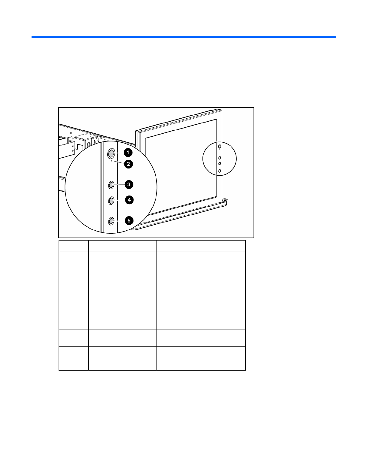
Component identification
Front Panel LEDs and Buttons
Item Description Function
1 Power On/Off button Powers the monitor on and off.
2 Power Indicator LED Indicates the power states of the HP
TFT7210R.
• Green—full power
• Amber—Sleep mode (on page
11) and Input Signal Out of
Range (on page 11)
3 Plus (+) button Scrolls up in the OSD menus and
adjusts the functions.
4 Minus (-) button Scrolls down in the OSD menus and
adjusts the functions.
5 Menu Select button Launches the first and second level
OSD menus and exits the menus
and OSD.
Component identification 5
Page 6

Installation
Installation Checklist
Before installation, refer to the following list to be sure that all of the listed components were received.
Kit contents
• HP TFT7210R
• HP 1U Adjustable Toolless Rails
• Brace rail assembly
o Brace rail
o Cable management arm
• Lock plates
• M6 screws
• 6-32 screws
• High-voltage power cord (10 ft), C13-C14
This kit might contain extra hardware for your convenience.
Installing the HP TFT7210R
1. Align the lower edge of the rack template with the top of the previous rack component, and push the
tabs in to hold the rack template in place. Mark the rack to indicate where the HP 1U Adjustable
Toolless Rails are to be located.
2. Align the HP 1U Adjustable Toolless Rails with the holes marked with the rack template, and snap
them into place.
a. Snap one end of the HP 1U Adjustable Toolless Rails into the Retma rails.
b. Extend the other half of the HP 1U Adjustable Toolless Rails to meet the appropriate rack depth,
and snap them into place.
NOTE: If the HP 1U Adjustable Toolless Rails do not snap into place, be sure that they align
with the holes marked with the rack template. The holes marked with the rack template must be
in the same location for the front and rear of the rack.
Installation 6
Page 7
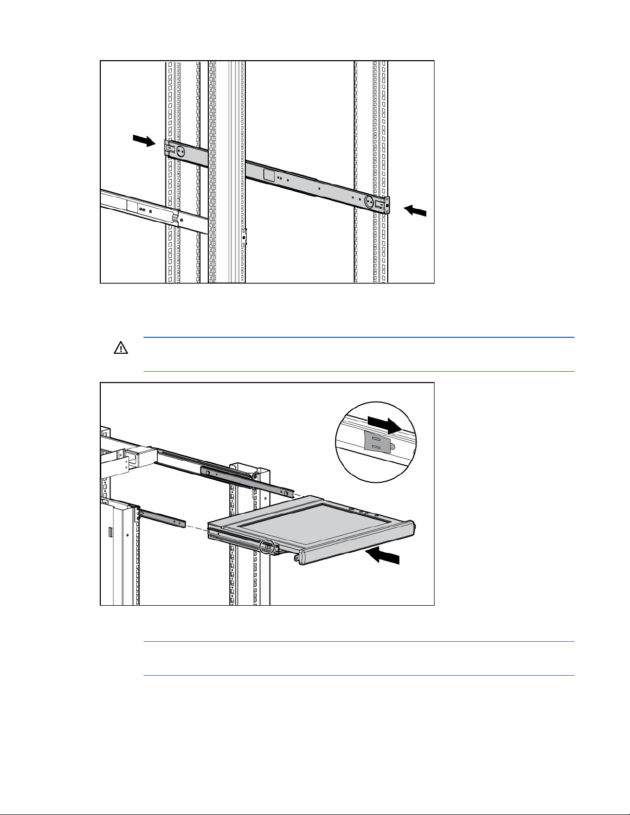
3. Extend the inner slides until they lock into place.
4. Align the HP TFT7210R with the extended inner slides, and pull the release mechanisms toward you
while inserting the HP TFT7210R into the rack.
WARNING: To reduce the risk of personal injury, release the release mechanisms after
pushing the HP TFT7210R slightly forward.
5. Slide the brace rail assembly into the HP 1U Adjustable Toolless Rails from the rear of the rack,
ensuring that the cable access hole faces the left side of the rack.
NOTE: The cable access hole must be positioned on the left side of the rack to enable
appropriate routing of the cables.
Installation 7
Page 8
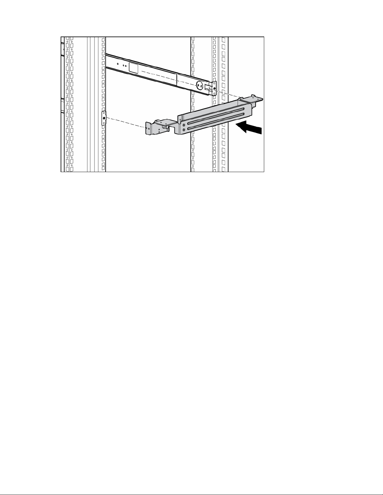
6. Align the screw holes on the brace rail with the screw holes on the HP 1U Adjustable Toolless Rails.
Installation 8
Page 9
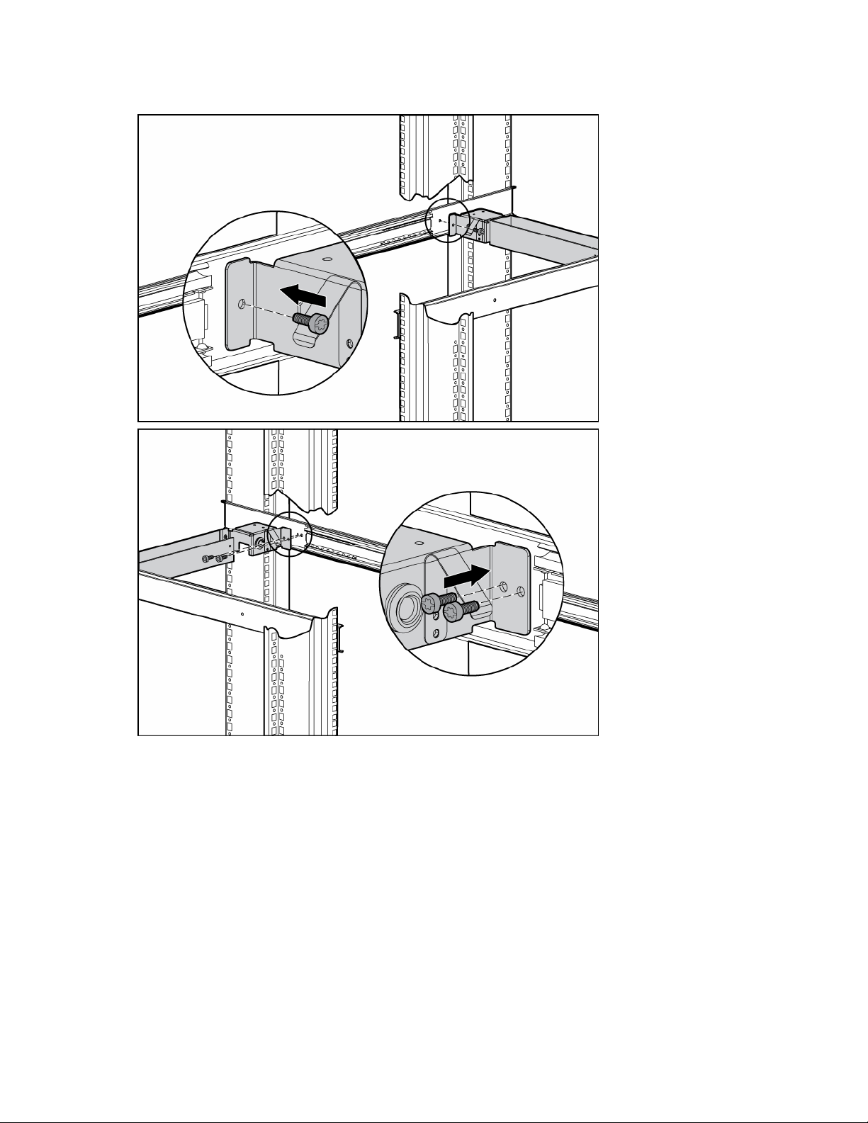
7. Secure the brace rail to the HP 1U Adjustable Toolless Rails by inserting three screws and tightening
them.
Installation 9
Page 10
8. Attach the cable management arm to the rear of the HP TFT7210R with two screws.
9. Route the cables and plug in the HP TFT7210R.
Installation 10
Page 11

Operational overview
Powering On and Off the HP TFT7210R
Press the Power On/Off button.
Accessing the OSD main menu
1. Press the Menu Select button on the front panel ("Front Panel LEDs and Buttons" on page 5). The
OSD Main menu appears and the default settings are shown when first accessing this menu.
2. Scroll down by pressing the Minus (-) button, or scroll up by pressing Plus (+) button.
3. Press the Menu Select button to activate the highlighted menu item.
If the Menu Select, Minus (-), or Plus (+) buttons remain untouched for the time duration that has been set
by the OSD Timeout (on page 18) function, any new settings that have not been saved will be discarded
and the previously saved settings are restored.
Exiting the OSD Main Menu
From the OSD Main menu, highlight Exit, and then press the Menu Select button to exit and close the OSD
Main menu.
Sleep Mode
After losing video signal, for supported video resolutions, a "Check Cable" message appears and is
stationary for two seconds. The display then goes blank, the monitor powers off, and the LED is amber.
For unsupported video modes that exceed 1280 X 1024 at 76 Hz, the display has a black background,
the LED is amber, and a "Selected resolution is not within recommended range of operation" message
appears for 20 seconds. After losing video signal, the message disappears.
Input signal out of range
An input signal that is outside the normal range of operation defined by the capabilities of the HP
TFT7210R, causes a "Selected resolution is not within recommended range of operation" message to
appear for 30 seconds.
Operational overview 11
Page 12

OSD main menu functions
Auto Setup
When selected, the Auto Setup menu activates the Image Control process and performs four functions
automatically:
• Auto Level—Automatically adjusts the black and white levels of the display
• Auto Position—Automatically adjusts the position of the display
• Auto Phase—Automatically adjusts the phase
• Auto Clock—Adjusts the output clock per line to match input
Brightness
When selected, the Brightness menu activates the Brightness Adjustment screen. A slider bar appears to
allow the adjustment of the back light brightness.
• Plus (+) increases the current value.
• Minus (-) decreases the current value.
• Menu Select accepts the current value and exits the slider bar.
Contrast
When selected, the Contrast menu activates the Contrast Adjustment screen. A slider bar appears to allow
the adjustment of the display contrast. Contrast adjustments are more discernible when the display
background is white. Contrast launches Auto Level (on page 12) if the color values are out of range.
• Plus (+) increases the current value.
• Minus (-) decreases the current value.
• Menu Select accepts the current value and exits the slider bar.
Image Adjust
The Image Adjust menu contains the following sub-menus:
• Horizontal Position (on page 13)
• Vertical Position (on page 13)
• Image Enhancement (on page 13)
• Color (on page 13)
• Advanced (on page 15)
OSD main menu functions 12
Page 13

• Exit
Within the menu:
• Plus (+) moves up a selection.
• Minus (-) moves down a selection.
• Menu Select activates one of the actions.
Horizontal Position
When selected, a slider bar appears to allow the adjustment of the display horizontal position.
• Plus (+) moves window to the right.
• Minus (-) moves the window to the left.
• Menu Select accepts the location and exits back to the sub-menu.
Vertical Position
When selected, a slider bar appears to allow the adjustment of the display vertical position.
• Plus (+) moves the window up.
• Minus (-) moves the window down.
• Menu Select accepts the location and exits back to sub-menu.
Image Enhancement
The Image Enhancement contains the following choices:
Color
• Context Sensitive—Allows text to be sharpened and graphic images smoothed on a per-pixel basis
• Text (sharp)—Allows sharper text by using a high sharpening filter
• Video (smooth)—Allows sharper graphics by using a low sharpening filter
Within the menu:
• Plus (+) moves up a selection and activates that choice.
• Minus (-) moves down a selection and activates that choice.
• Menu Select exits, leaving the last selection as the new default.
The Color menu contains the following sub-menus:
• Color Temp (on page 14)
• RGB Adjust (on page 14)
• Black Level Adjust (on page 15)
• Exit
Within the menu:
OSD main menu functions 13
Page 14

• Plus (+) moves up a selection.
• Minus (-) moves down a selection.
• Menu Select activates one of the actions.
Color Temp
The Color Temp menu contains the following choices:
• Cool—A Gamma table for Cool temperatures loads all three-color channels
• Neutral—A Gamma table for Neutral temperatures loads all three-color channels
• Warm—A Gamma table for Warm temperatures loads all three-color channels
• Exit
Within the menu:
• Plus (+) moves up a selection and activates that choice.
• Minus (-) moves down a selection and activates that choice.
• Menu Select exits, leaving the last selection as the new default.
RGB Adjust
The RGB Adjust menu contains the following sub-menus:
• RGB Adjust Red (on page 14)
• RGB Adjust Green (on page 14)
• RGB Adjust Blue (on page 15)
• Exit
Within the menu:
• Plus (+) moves up a selection.
• Minus (-) moves down a selection.
• Menu Select activates one of the actions.
RGB Adjust Red
When selected, a slider bar appears to allow the adjustment of the Red color in the display.
• Plus (+) increases the current value.
• Minus (-) decreases the current value.
• Menu Select accepts the current value and exits the slider bar.
RGB Adjust Green
When selected, a slider bar appears to allow the adjustment of the Green color in the display.
• Plus (+) increases the current value.
• Minus (-) decreases the current value.
• Menu Select accepts the current value and exits the slider bar.
OSD main menu functions 14
Page 15

RGB Adjust Blue
When selected, a slider bar appears to allow the adjustment of the Blue color in the display.
• Plus (+) increases the current value.
• Minus (-) decreases the current value.
• Menu Select accepts the current value and exits the slider bar.
Black Level Adjust
The Black Level Adjust menu contains the following sub-menus:
• Black Level Adjust Red (on page 15)
• Black Level Adjust Green (on page 15)
• Black Level Adjust Blue (on page 15)
• Exit
Within the menu:
• Plus (+) moves up a selection.
• Minus (-) moves down a selection.
• Menu Select activates one of the actions.
Black Level Adjust Red
When selected, a slider bar appears to allow the adjustment of the Black level for Red in the display.
• Plus (+) increases the current value.
• Minus (-) decreases the current value.
• Menu Select accepts the current value and exits the slider bar.
Black Level Adjust Green
When selected, a slider bar appears to allow the adjustment of the Black level for Green in the display.
• Plus (+) increases the current value.
• Minus (-) decreases the current value.
• Menu Select accepts the current value and exits the slider bar.
Black Level Adjust Blue
When selected, a slider bar appears to allow the adjustment of the Black level for Blue in the display.
• Plus (+) increases the current value.
• Minus (-) decreases the current value.
• Menu Select accepts the current value and exits the slider bar.
Advanced
The Advanced menu contains the following sub-menus:
OSD main menu functions 15
Page 16

• Phase Adjust (on page 16)
• Clock Adjust (on page 16)
• Exit
Within the menu:
• Plus (+) moves up a selection.
• Minus (-) moves down a selection.
• Menu Select activates one of the actions.
Phase Adjust
When selected, a slider bar appears to allow the adjustment of the analog phase signal.
• Plus (+) increases the current value.
• Minus (-) decreases the current value.
• Menu Select accepts the current value and exits the slider bar.
Clock Adjust
When selected, a slider bar appears to allow the adjustment of the horizontal clock signal.
• Plus (+) increases the current value.
• Minus (-) decreases the current value.
• Menu Select accepts the current value and exits the slider bar.
Languages
The Languages menu contains the following languages:
• English
• Dutch
• French
• German
• Italian
• Japanese
• Portuguese
• Simple Chinese
• Spanish
• Swedish
Within the menu:
• Plus (+) moves up a selection.
• Minus (-) moves down a selection.
• Menu Select activates one of the actions.
OSD main menu functions 16
Page 17

OSD Settings
The OSD Settings menu contains the following sub-menus:
• OSD Position (on page 17)
• OSD Size (on page 18)
• OSD Timeout (on page 18)
• Exit
Within the menu:
• Plus (+) moves up a selection.
• Minus (-) moves down a selection.
• Menu Select activates one of the actions.
OSD Position
The OSD Position menu contains the following sub-menus:
• OSD Horizontal Position (on page 17)
• OSD Vertical Position (on page 17)
• Exit
Within the menu:
• Plus (+) moves up a selection.
• Minus (-) moves down a selection.
OSD Horizontal Position
• Menu Select activates one of the actions.
When selected, the OSD Horizontal Position menu allows the location of the OSD to move horizontally on
the display.
• Plus (+) moves the OSD window to the right.
• Minus (-) moves the OSD window to the left.
• Menu Select accepts the location and exits back to the sub-menu.
OSD Vertical Position
When selected, the OSD Vertical Position allows the location of the OSD to move vertically on the
display.
• Plus (+) moves the OSD window up.
• Minus (-) moves the OSD window down.
• Menu Select accepts the location and exits back to sub-menu.
OSD main menu functions 17
Page 18

OSD Size
The OSD Size menu contains the following choices:
• OSD Size Normal—Sets the character to normal size
• OSD Size Double—Sets the character to double size
Within the menu:
• Plus (+) moves up a selection and activates that choice.
• Minus (-) moves down a selection and activates that choice.
• Menu Select exits, leaving the last selection as the new default.
OSD Timeout
The OSD Timeout menu allows the adjustment of the OSD Timeout feature. The timeout ranges from 5 to
55 seconds with 5-second intervals.
• Plus (+) increases the time the OSD appears.
• Minus (-) decreases the time the OSD appears.
• Menu Select accepts the current value and exits the slider bar.
Restore Factory Presets
When selected, the OSD Main menu activates the factory presets reset and exits the OSD Main menu.
The following settings are restored:
• Auto Level (on page 12)
• Brightness (on page 12)
• Contrast (on page 12)
• Horizontal Position (on page 13)
• Vertical Position (on page 13)
• Color Temp (on page 14)
• RGB Adjust (on page 14)
• Black Level Adjust (on page 15)
• OSD Horizontal Position (on page 17)
• OSD Vertical Position (on page 17)
• OSD Size (on page 18)
• OSD Timeout (on page 18)
Information
When selected, the following unit information appears:
• Model number
OSD main menu functions 18
Page 19

• Micro Code Version
• Exit
OSD main menu functions 19
Page 20

Maintenance
Maintenance guidelines
To protect the HP TFT7210R from overheating and other types of damage:
• Use only a power source and connection appropriate for the HP TFT7210R, as indicated on the
agency label.
• If an extension cord or power strip is used, be sure that the cord or strip is rated for the product.
Also, be sure that the total ampere ratings of all products plugged into the extension cord or power
strip do not exceed 80% of the extension cord or strip ampere ratings label.
• Do not overload an electrical outlet, power strip, or convenience receptacle. The overall system load
must not exceed 80% of the branch circuit rating. If power strips are used, the load should not
exceed 80% of the power strip input rating.
• Install the HP TFT7210R near an outlet that you can reach easily. Disconnect the product by grasping
the plug firmly and pulling it from the outlet. Never disconnect it by pulling the cord.
• Unplug the HP TFT7210R from the wall outlet before cleaning. Do not use liquid cleaners or aerosol
cleaners.
• Slots and openings in the monitor are provided for ventilation. These openings must not be blocked
or covered. Never push objects of any kind into these slots or openings.
• Do not drop the HP TFT7210R or place it on an unstable surface.
• Do not allow anything to rest on the power cord. Do not walk on the cord.
• Keep the original packing material and box in a storage area in case you need them later.
• Keep the HP TFT7210R in a well-ventilated area, away from excessive light, heat, and moisture.
Keep the monitor away from high-capacity transformers, electric motors, and other strong magnetic
fields.
• Do not attempt to service this product yourself. Adjust only those controls that are covered by the
operating instructions. If the HP TFT7210R is not operating properly or has been dropped or
damaged, contact your HP authorized dealer, reseller, or service provider.
Cleaning the HP TFT7210R
1. Power off the HP TFT7210R ("Powering On and Off the HP TFT7210R" on page 11).
2. Wipe the screen with a soft, clean cloth.
If the screen requires additional cleaning, use any anti-static CRT screen cleaner.
CAUTION: Do not use benzene, thinner, ammonia, or any volatile substance to clean the
screen or cabinet. These chemicals can damage the screen. Never use water to clean a
screen.
Maintenance 20
Page 21

Storing the HP TFT7210R
1. Pull the release mechanism toward you with your index fingers to unlock the inner slides.
2. In the same motion, release the release mechanism and move the HP TFT7210R forward into the
stored position.
WARNING: To reduce the risk of personal injury, release the release mechanisms after
pushing the HP TFT7210R slightly forward.
Moving a rack with the HP TFT7210R installed
When moving the HP TFT7210R installed in a rack, HP recommends installing the lock plates.
1. Fully extend the HP TFT7210R until the slides lock into place.
2. Place a lock plate behind the corner of the front plastic bezel, being sure that the top and bottom
holes are aligned with the front plastic bezel pins.
3. From behind the corner of the front plastic bezel, insert a 6-32 screw into the middle hole on the lock
plate, securing it to the HP TFT7210R.
4. Repeat steps 2 and 3 to install the other lock plate.
5. Push the HP TFT7210R back into the rack.
6. Insert an M6 screw into the only visible lock plate hole, securing the HP TFT7210R to the rail.
Maintenance 21
Page 22

7. Repeat step 6 for the other lock plate.
Maintenance 22
Page 23
Specifications
Physical Specifications
Parameter Specification
Monitor height 34.29 cm (13.5 in)
Monitor depth 4.25 cm (1.67 in)
Monitor width 39.6 cm (15.59 in)
Unit weight 6.12 kg (13.5 lb)
Environmental Specifications
Feature Specification
Operating temperature
(independent of altitude)
Nonoperating temperature
(independent of altitude)
Relative humidity 20 to 80%; noncondensing
Operating altitude 0 to 3,658 m (12,000 ft)
Nonoperating altitude 0 to 12,192 m (40,000 ft)
5 to 35°C (41 to 95°F)
-20 to 60°C (-4 to 140°F)
Specifications 23
Page 24

Removing the rails
Removing the HP 1U Adjustable Toolless Rails
1. Remove the HP TFT7210R.
2. Remove the brace rail assembly.
3. Locate the spring release.
4. Place your hand on the outside of the HP 1U Adjustable Toolless Rail so that you can move the
spring release.
5. Gently move the spring release toward the inside of the rack (1) while moving the HP 1U Adjustable
Toolless Rail out toward you and away from the rack (2).
NOTE: If you cannot gain access to the spring release from the outside of the HP 1U
Adjustable Toolless Rail, a tool might be required to unlock the spring release from the unit side
of the HP 1U Adjustable Toolless Rail.
6. Repeat the previous steps for the other HP 1U Adjustable Toolless Rail.
Removing the rails 24
Page 25

Technical support
HP contact information
For the name of the nearest HP authorized reseller:
• In the United States, see the HP US service locator webpage (http://www.hp.com/service_locator).
• In other locations, see the Contact HP worldwide (in English) webpage
(http://welcome.hp.com/country/us/en/wwcontact.html
For HP technical support:
• In the United States, for contact options see the Contact HP United States webpage
(http://welcome.hp.com/country/us/en/contact_us.html
o Call 1-800-HP-INVENT (1-800-474-6836). This service is available 24 hours a day, 7 days a
week. For continuous quality improvement, calls may be recorded or monitored.
).
). To contact HP by phone:
o If you have purchased a Care Pack (service upgrade), call 1-800-633-3600. For more
information about Care Packs, refer to the HP website (http://www.hp.com
• In other locations, see the Contact HP worldwide (in English) webpage
(http://welcome.hp.com/country/us/en/wwcontact.html
Before you contact HP
Be sure to have the following information available before you call HP:
• Technical support registration number (if applicable)
• Product serial number
• Product model name and number
• Product identification number
• Applicable error messages
• Add-on boards or hardware
• Third-party hardware or software
• Operating system type and revision level
).
).
Technical support 25
Page 26

Regulatory compliance notices
Regulatory compliance identification numbers
For the purpose of regulatory compliance certifications and identification, this product has been assigned
a unique regulatory model number. The regulatory model number can be found on the product nameplate
label, along with all required approval markings and information. When requesting compliance
information for this product, always refer to this regulatory model number. The regulatory model number is
Federal Communications Commission notice
not the marketing name or model number of the product.
Part 15 of the Federal Communications Commission (FCC) Rules and Regulations has established Radio
Frequency (RF) emission limits to provide an interference-free radio frequency spectrum. Many electronic
devices, including computers, generate RF energy incidental to their intended function and are, therefore,
covered by these rules. These rules place computers and related peripheral devices into two classes, A
and B, depending upon their intended installation. Class A devices are those that may reasonably be
expected to be installed in a business or commercial environment. Class B devices are those that may
reasonably be expected to be installed in a residential environment (for example, personal computers).
The FCC requires devices in both classes to bear a label indicating the interference potential of the device
as well as additional operating instructions for the user.
FCC rating label
The FCC rating label on the device shows the classification (A or B) of the equipment. Class B devices
have an FCC logo or ID on the label. Class A devices do not have an FCC logo or ID on the label. After
you determine the class of the device, refer to the corresponding statement.
Class A equipment
This equipment has been tested and found to comply with the limits for a Class A digital device, pursuant
to Part 15 of the FCC Rules. These limits are designed to provide reasonable protection against harmful
interference when the equipment is operated in a commercial environment. This equipment generates,
uses, and can radiate radio frequency energy and, if not installed and used in accordance with the
instructions, may cause harmful interference to radio communications. Operation of this equipment in a
residential area is likely to cause harmful interference, in which case the user will be required to correct
the interference at personal expense.
Class B equipment
This equipment has been tested and found to comply with the limits for a Class B digital device, pursuant
to Part 15 of the FCC Rules. These limits are designed to provide reasonable protection against harmful
interference in a residential installation. This equipment generates, uses, and can radiate radio frequency
Regulatory compliance notices 26
Page 27

energy and, if not installed and used in accordance with the instructions, may cause harmful interference
to radio communications. However, there is no guarantee that interference will not occur in a particular
installation. If this equipment does cause harmful interference to radio or television reception, which can
be determined by turning the equipment off and on, the user is encouraged to try to correct the
interference by one or more of the following measures:
• Reorient or relocate the receiving antenna.
• Increase the separation between the equipment and receiver.
• Connect the equipment into an outlet on a circuit that is different from that to which the receiver is
connected.
• Consult the dealer or an experienced radio or television technician for help.
Declaration of conformity for products marked with the FCC logo, United States only
This device complies with Part 15 of the FCC Rules. Operation is subject to the following two conditions:
(1) this device may not cause harmful interference, and (2) this device must accept any interference
received, including interference that may cause undesired operation.
For questions regarding this product, contact us by mail or telephone:
• Hewlett-Packard Company
P. O. Box 692000, Mail Stop 530113
Houston, Texas 77269-2000
• 1-800-HP-INVENT (1-800-474-6836). (For continuous quality improvement, calls may be recorded
or monitored.)
For questions regarding this FCC declaration, contact us by mail or telephone:
• Hewlett-Packard Company
P. O. Box 692000, Mail Stop 510101
Houston, Texas 77269-2000
• 1281-514-3333
To identify this product, refer to the part, series, or model number found on the product.
Modifications
The FCC requires the user to be notified that any changes or modifications made to this device that are
not expressly approved by Hewlett-Packard Company may void the user’s authority to operate the
equipment.
Cables
Connections to this device must be made with shielded cables with metallic RFI/EMI connector hoods in
order to maintain compliance with FCC Rules and Regulations.
Regulatory compliance notices 27
Page 28

Canadian notice (Avis Canadien)
Class A equipment
This Class A digital apparatus meets all requirements of the Canadian Interference-Causing Equipment
Regulations.
Cet appareil numérique de la classe A respecte toutes les exigences du Règlement sur le matériel
brouilleur du Canada.
Class B equipment
This Class B digital apparatus meets all requirements of the Canadian Interference-Causing Equipment
Regulations.
Cet appareil numérique de la classe B respecte toutes les exigences du Règlement sur le matériel
brouilleur du Canada.
European Union regulatory notice
This product complies with the following EU Directives:
• Low Voltage Directive 2006/95/EC
• EMC Directive 2004/108/EC
• Machinery Directive 98/37/EEC
Compliance with these directives implies conformity to applicable harmonized European standards
(European Norms) which are listed on the EU Declaration of Conformity issued by Hewlett-Packard for this
product or product family.
This compliance is indicated by the following conformity marking placed on the product:
This marking is valid for non-Telecom products and EU harmonized Telecom products (e.g. Bluetooth).
This marking is valid for EU non-harmonized Telecom products.
*Notified body number (used only if applicable—refer to the product label)
Hewlett-Packard GmbH, HQ-TRE, Herrenberger Strasse 140, 71034 Boeblingen, Germany
Regulatory compliance notices 28
Page 29
Japanese notice
BSMI notice
Korean notice
Class A equipment
Class B equipment
Regulatory compliance notices 29
Page 30

Disposal of waste equipment by users in private households in the European Union
This symbol on the product or on its packaging indicates that this product must not be disposed of with
your other household waste. Instead, it is your responsibility to dispose of your waste equipment by
handing it over to a designated collection point for the recycling of waste electrical and electronic
equipment. The separate collection and recycling of your waste equipment at the time of disposal will
help to conserve natural resources and ensure that it is recycled in a manner that protects human health
and the environment. For more information about where you can drop off your waste equipment for
recycling, please contact your local city office, your household waste disposal service or the shop
where you purchased the product.
Material disposal
This HP product contains the following material that might require special handling at end-of-life:
• Mercury in the fluorescent lamp in the display LCD.
Disposal of mercury might be regulated because of environmental considerations. For disposal or
recycling information, contact your local authorities or the Electronic Industries Alliance (EIA)
(http://www.eiae.org
).
Regulatory compliance notices 30
Page 31
Power cord requirements
Introduction to power cord requirements
The power cord set meets the requirements for use in the country where you purchased the equipment.
The voltage selection switch allows you to select the appropriate line voltage for the server.
Power cord sets for use in other countries must meet the requirements of the country where you use the
General requirements
server. For more information on power cord set requirements, contact your HP authorized dealer.
The requirements listed below are applicable to all countries:
• The length of the power cord must be at least 1.8 m (6.0 feet) and a maximum of 3.7 m (12 feet).
• The power cord set must be approved by an acceptable accredited agency responsible for
evaluation in the country where the power cord will be used.
• The power cord set must have a minimum current capacity and nominal voltage rating of
10A/125 volts AC, or 10A/250 volts AC, as required by the power system of each country.
• The appliance coupler must meet the mechanical configuration of an EN60320/IEC 320 Standard
Sheet C13 Connector, for mating with the appliance outlet on the computer.
Power cord set requirements by country
Use this table to identify the appropriate accredited agency in your country.
Country Accredited agency Applicable note numbers
Australia EANSW 1
Austria OVE 1
Belgium CEBC 1
Canada CSA 2
Denmark DEMKO 1
Finland SETI 1
France UTE 1
Germany VDE 1
Italy IMQ 1
Japan JIS 3
Norway NEMKO 1
Sweden SEMKO 1
Switzerland SEV 1
Power cord requirements 31
Page 32

Country Accredited agency Applicable note numbers
United Kingdom BSI 1
United States UL 2
1
NOTE: Flexible cord must be <HAR> Type HO5VV-F, 3-conductor, 1.0 mm2 conductor size.
Power cord set fittings (appliance coupler and wall plug) must bear the certification mark of the
2
agency responsible for evaluation in the country where it will be used.
NOTE: Flexible cord must be Type SVT or equivalent, No. 18 AWG, 3-conductor. Wall plug
must be a two-pole grounding type with a NEMA 5-15P (15 A, 125 V).
3
NOTE: Appliance coupler, flexible cord, and wall plug must bear a T mark and registration
number in accordance with the Japanese Dentori Law. Flexible cord must be Type VCT or
VCTF, 3-conductor, 1.0 mm2 conductor size. Wall plug must be a two-pole grounding type
with a Japanese Industrial Standard C8303 (7A, 125V) configuration.
Power cord requirements 32
Page 33

Electrostatic discharge
Preventing electrostatic discharge
To prevent damaging the system, be aware of the precautions you need to follow when setting up the
system or handling parts. A discharge of static electricity from a finger or other conductor may damage
system boards or other static-sensitive devices. This type of damage may reduce the life expectancy of the
device.
To prevent electrostatic damage:
• Avoid hand contact by transporting and storing products in static-safe containers.
• Keep electrostatic-sensitive parts in their containers until they arrive at static-free workstations.
• Place parts on a grounded surface before removing them from their containers.
• Avoid touching pins, leads, or circuitry.
• Always be properly grounded when touching a static-sensitive component or assembly.
Grounding methods to prevent electrostatic discharge
Several methods are used for grounding. Use one or more of the following methods when handling or
installing electrostatic-sensitive parts:
• Use a wrist strap connected by a ground cord to a grounded workstation or computer chassis. Wrist
straps are flexible straps with a minimum of 1 megohm ±10 percent resistance in the ground cords.
To provide proper ground, wear the strap snug against the skin.
• Use heel straps, toe straps, or boot straps at standing workstations. Wear the straps on both feet
when standing on conductive floors or dissipating floor mats.
• Use conductive field service tools.
• Use a portable field service kit with a folding static-dissipating work mat.
If you do not have any of the suggested equipment for proper grounding, have an authorized reseller
install the part.
For more information on static electricity or assistance with product installation, contact an authorized
reseller.
Electrostatic discharge 33
Page 34

Acronyms and abbreviations
CRT
cathode-ray tube
LED
light-emitting diode
OSD
on-screen display
RGB
red green blue
Acronyms and abbreviations 34
Page 35

Index
A
installation 6
installation checklist 6
Auto Setup 12
B
Black Level Adjust 15
Brightness 12
BSMI notice 29
C
cables, FCC compliance 27
class A equipment 26
class B equipment 26
cleaning the unit 20
Clock Adjust 16
color 13
components 5
contact information 25
Contrast 12
D
Declaration of Conformity 27
E
electrostatic discharge 33
environmental specifications 23
J
Japanese notice 29
K
kit contents 6
Korean notices 29
L
languages 16
M
maintenance 20
material disposal 30
modifications, FCC notice 27
O
operational overview 11
OSD Horizontal Position 17
OSD position 17
OSD settings 17
OSD Size 18
OSD Timeout 11, 18
OSD Vertical Position 17
F
factory default settings 18
Federal Communications Commission (FCC)
notice 26, 27
front panel LEDs 5
H
Horizontal Position 13
I
Image adjust 12
Image Enhancement 13
Input Signal Out of Range 11
P
Phase adjust 16
physical specifications 23
power cord 31
Power On/Standby button 11
R
rails, removing 24
regulatory compliance identification numbers 26
regulatory compliance notices 26, 30
RGB Adjust 14
Index 35
Page 36

S
Sleep Mode 11
specifications 23
storing the unit 21
T
technical support 25
V
Vertical Position 13
Index 36
 Loading...