

Page 1

NeoLinux 4.0 Thin Client
USER MANUAL
Page 2

© 2007 by Neoware, Inc.
3200 Horizon Drive,
King of Prussia, PA 19406 USA
Tel.: +1-610-277-8300
Fax: +1-610-771-4200
Email: info@neoware.com
Web: http://www.neoware.com
This manual is copyrighted by Neoware, Inc. All rights are reserved. This document may not, in
whole or in part, be copied, photocopied, reproduced, translated, or reduced to any electronic
medium or machine-readable form without prior consent, in writing, from Neoware, Inc.
Neoware, NeoLinux, Neostation, Eon, Capio, ThinSTAR, TeemTalk, ezDevice Manager, @work,
and @workStation are trademarks or registered trademarks of Neoware, Inc. Java is a registered
trademark of Sun Microsystems, Inc. Microsoft and Windows are registered trademarks of
Microsoft Corporation. MetaFrame, WinFrame, and ICA are registered trademarks of Citrix Systems, Inc. Other trademarks used in this manual are the property of their respective owners.
Disclaimer: The information provided in this manual is intended for instructional purposes only
and is subject to change without notice. Neoware, Inc. accepts no responsibility or liability for
errors, omissions, or misleading information that may be contained in this manual.
April 2007
ii
Page 3

FCC Regulatory & Safety Information
FCC regulatory and safety information can be found in the Quick Start Guide that came
with your thin client, and on the Support section of the Neoware website which can be
found at:
http://www.neoware.com/support.html
CANADA ICES/NMB-003 Class/Classe (B)
This Class B digital apparatus complies with Canadian ICES-003.
Cet appareil numérique de la classe B est conforme à la norme NMB-003 du Canada.
Neoware Hardware Warranty
Neoware hardware warranties can be found in the Quick Start Guide that came with your
thin client, and on the Support section of the Neoware website which can be found at:
http://www.neoware.com/support.html
Lead Content Warning
Many PC products and accessories contain cords, cables or wires, such as power cords or
cords to connect the accessory to a PC. If this product has such a cord, cable or wire, then
the following warning applies:
WARNING: Handling the cord on this product will expose you to lead, a chemical known
to the State of California to cause cancer, and birth defects or other reproductive harm.
Wash hands after handling.
iii
Page 4

Safety Instructions
Please read these safety instructions carefully and keep this user manual for later reference.
1 Before removing the outer case from the thin client, always disconnect the AC power cord to
prevent the possibility of dangerous electrical shock.
2 Before cleaning, disconnect the thin client from AC power. Do not use liquid or sprayed clean-
ing products to clean the unit. Instead, use a moistened sheet or cloth for cleaning.
3 Do not expose the thin client to excessive humidity.
4 Be sure to install the thin client on a secure surface. A falling device could cause injury.
5 Place the power cord in such a way to avoid people stepping on it. Do not place anything over
the power cord.
6 Be sure to note all cautions and warnings on the thin client.
7 If the thin client is not used for a long period of time, disconnect the AC power to avoid damage
caused by voltage transients.
8 Never pour any liquid into any thin client openings. This could cause fire or electrical shock.
9 If one of the following situations occurs, be sure to get the thin client checked by a qualified
service technician:
• The power cord or plug is damaged.
• Liquid penetrates the thin client case.
• The thin client is exposed to moisture.
• The thin client does not work well or you cannot get it to work according to the user manual.
• The thin client has been dropped or damaged.
• The thin client has obvious signs of breakage.
10 The thin client should be stored and used only in temperature and humidity controlled environ-
ments. Storing thin clients below -20°C (-4°F) or above 60°C (140°F) may cause damage.
11 The sound pressure level at the operators position according to IEC 704-1:1982 is equal or less
to 70dB(A).
12 The input power cord shall be minimum H05VV-F, 3G, 0.75mm², rate minimum 6A.
13 The thin client should be used only where ambient air temperatures are maintained below 40°C.
iv
Page 5

Table of Contents
FCC Regulatory & Safety Information iii
CANADA ICES/NMB-003 Class/Classe (B) iii
Neoware Hardware Warranty iii
Lead Content Warning iii
Safety Instructions iv
Table of Contents v
NeoLinux Thin Client User Manual
CHAPTER 1
CHAPTER 2
Introduction 1
What is a NeoLinux Thin Client? 1
The Thin Client 1
NeoLinux 2
Getting More Information 2
The Internet 2
Technical Support 3
About This Manual 3
Overview of Contents 3
Terms & Conventions 6
Setting Up Your Neoware Thin Client 7
Unpacking Your Neoware Thin Client 7
Connecting the Components 8
v
Page 6

Tabl e of Con ten ts
Back Panel Connectors 8
Connecting the Cables 9
Connecting Parallel & Serial Peripheral Devices 9
Arranging Your Work Area 10
CHAPTER 3
Getting Started 11
Starting Up Your Thin Client 11
Network Configuration 12
Creating a New Connection 12
Starting a Connection 16
Using the Connection Manager 17
Displaying the Connection Manager 17
Making a Connection 17
T o olbar Options 18
Logging Off & Shutting Down 18
Kiosk Mode 19
Enabling Kiosk Mode 19
Security 20
Setting a Password 20
Menu Options 22
Displaying the Menu 22
Connection Selection 22
System Tools 23
Control Panel 26
Logging Off 27
Rebooting the System 27
Shutting Down Your Thin Client 27
Keyboard Shortcuts 28
Menu Item Selection 28
Using the Keyboard to Navigate the Display 28
Changing Settings 29
Using the Desktop 29
Setting the Date, Time & Time Zone 29
Date and Time 29
vi
Page 7

Table of Contents
Time Zone 31
Sound Settings 31
Power Options 33
Managing & Updating Thin Client Software 34
Displaying System Information 35
Boot Options 36
CHAPTER 4
CHAPTER 5
Network Configuration 37
Introduction 37
Displaying the Network Connections Window 38
On-board LAN 39
The IP Settings Tab 40
The DHCP Options Tab 42
On-board WiFi 44
The Wireless Tab 45
The Security Tab 47
The Network Tab 49
The DHCP Options Tab 52
General Network Settings 53
The General Tab 53
The Hosts Tab 55
ICA Connection Configuration 57
Introduction 57
Creating a New ICA Connection 58
The Edit New ICA Connection Dialog 62
The Network Tab 62
The Connection Tab 64
The Local Resources Tab 66
The Window Tab 68
The Application Tab 70
The Firewall Tab 72
The Server Location Tab 73
The Extra Keys Tab 75
vii
Page 8

Tabl e of Con ten ts
The Common Settings Tab 77
The ICA General Settings Dialog 80
The Options Tab 81
The Window Tab 84
The Server Location Tab 86
The Firewall Tab 89
CHAPTER 6
CHAPTER 7
RDP Connection Configuration 91
Introduction 91
Creating a New RDP Connection 92
The Edit New RDP Connection Dialog 95
The Network Tab 95
The Window Tab 97
The Options Tab 99
The Local Resources Tab 102
The Experience Tab 104
The Common Settings Tab 106
The RDP General Settings Dialog 109
TeemTalk Connection Configuration 111
Introduction 111
Creating a New TeemTalk Connection 112
The Edit New TeemTalk Connection Dialog 115
The Network Tab 115
The Backup Tab 118
The General Tab 119
The Display Tab 121
The Color Tab 125
The Keyboard Macros Tab 126
The Common Settings Tab 128
The Emulation Tab 131
The TeemTalk General Settings Dialog 132
The General Tab 133
The Color Tab 134
viii
Page 9

The Printer Tab 136
Table of Contents
CHAPTER 8
CHAPTER 9
CHAPTER 10
Firefox Connection Configuration 139
Introduction 139
Creating a New Firefox Connection 140
The Edit New Firefox Connection Dialog 143
The Network Tab 143
The Common Settings Tab 145
The Firefox General Settings Dialog 148
The General Tab 149
The Proxy Tab 151
The Tabbed Browsing Tab 152
The Security Tab 154
The Javascript Tab 155
The Printer Tab 156
PNAgent Connection Configuration 157
Introduction 157
Creating a New PNAgent Connection 158
The Common Settings Tab 161
Custom Connection Configuration 165
Creating a New Custom Connection 165
The Common Settings Tab 168
CHAPTER 11
CHAPTER 12
SSH Connection Configuration 171
Creating a New SSH Connection 171
The Common Settings Tab 175
Telnet Connection Configuration 179
Creating a New Telnet Connection 179
The Common Settings Tab 182
ix
Page 10

Tabl e of Con ten ts
CHAPTER 13
CHAPTER 14
XDM Connection Configuration 185
Introduction 185
Creating a New XDM Connection 186
The Common Settings Tab 189
Using The Desktop 193
Introduction 193
Virtual Desktops 194
Desktop Menus 195
Right-click on Desktop 195
Right-click on Connection Icon 195
The Taskbar 196
Taskbar Display 196
Window Display 196
The Menu Button 197
The Desktop Button 198
Window Buttons 198
System Information 199
Using Windows 199
Moving & Resizing a Window 199
The Title Bar 199
Window Controls 200
Window List 202
The Control Panel Toolbar 203
CHAPTER 15
Display Configuration 205
Introduction 205
Display Settings 206
The Display Tab 207
The Monitor Tab 208
The Power Saving Tab 210
Touchscreen Settings 212
Desktop Settings 213
The Desktop Tab 213
x
Page 11

The Screensaver Tab 218
The Access Control List Tab 220
The Fontserver Tab 222
The Shadowing Tab 224
The X Resources Tab 226
Table of Contents
CHAPTER 16
CHAPTER 17
CHAPTER 18
CHAPTER 19
Mouse Configuration 229
Introduction 229
Displaying the Mouse Settings Dialog 229
Mouse Settings Dialog 230
Touchpad Configuration 233
Introduction 233
Displaying the Touchpad Settings Dialog 233
Touchpad Dialog Settings 234
Keyboard Configuration 237
Introduction 237
Displaying the Keyboard Settings Dialog 237
General Keyboard Settings 238
Keyboard Shortcuts 240
Printing Using LPD or ThinPrint 243
Introduction 243
Line Printer Settings 244
The General Tab 245
The Queues Tab 247
The Remote lpr Tab 248
ThinPrint Settings 250
CHAPTER 20
Storage Devices 253
Introduction 253
Storage Device Configuration 253
xi
Page 12

Tabl e of Con ten ts
CHAPTER 21
CHAPTER 22
CHAPTER 23
CHAPTER 24
Port Mapping 257
Introduction 257
Displaying the Port Settings Dialog 257
COM Port Settings 259
LPT1 Port Settings 262
USB Serial Port Settings 263
Managing Certificates 265
Introduction 265
Displaying the Certificates Dialog 265
The Certificates Dialog 266
Accessories 269
Comment Window 269
Command Prompt 270
SSH Connection 271
Updating Your Thin Client Software 273
Introduction 273
Software Update 274
xii
CHAPTER 25
CHAPTER 26
System Information 277
Displaying System Information 277
General System Information 278
Network Configuration Information 279
Testing Your Network 280
The Ping Tool 280
The DNS Lookup Tool 281
The Trace Route Tool 281
The Registry Editor 283
Introduction 283
Page 13

Displaying the Registry Editor 283
The Registry Editor Window 285
Modifying a Registry Key 286
Index 287
Table of Contents
xiii
Page 14

Tabl e of Con ten ts
xiv
Page 15

NeoLinux Thin Client User Manual
CHAPTER 1 Introduction
This chapter introduces NeoLinux thin clients and describes the
scope of this User Manual.
What is a NeoLinux Thin Client?
The Thin Client Neoware thin clients are sleek computing devices that contain no
hard drive, fan, or other moving parts, making them extremely
reliable and completely silent. Thin clients provide access to
programs running on network servers. Generally as you work, your
thin client sends keystrokes and mouse clicks to the server, which
responds with screen updates for your monitor. Most of the
processing occurs on the server. Due to the speed of modern
computer networks, this exchange happens as fast as, and
frequently faster than, processing on a personal computer.
Neoware thin clients can be used with standard VGA, SVGA, and
XVGA-type monitors, PS/2 or USB mouse and keyboard, and
other pointing devices.
Configurations vary with respect to the specific number of parallel
port, serial port(s), and USB ports that are provided. When available, these ports may be used for peripheral devices that may
include printers, modems, floppy drives, zip drives, cd-roms, and
bar code scanners. The version of software installed in your thin
client will determine which types of peripherals may be used.
1
Page 16

Introduction
Your thin client can automatically connect to either 10BaseT or
100BaseT (twisted-pair) Ethernet networks, as well as make serial
port connections with or without a modem.
NeoLinux Your thin client arrives with NeoLinux software internally pre-
installed in its local Flash disk memory. Using NeoLinux, your thin
client can initiate simultaneous, multiple connections (some models
are restricted to one connection only) to Windows Server 2003,
Windows 2000 Server, UNIX-based servers, mainframes, midrange
computers, intranets, and the Internet, depending on the software
version installed in the thin client.
Connections to Windows Server 2003 and Windows 2000 Server are
made via Citrix’s Independent Computing Architecture (ICA
tocol, as well as Remote Desktop Protocol (RDP).
Note: To make Windows connections using ICA, the server must be
running Citrix MetaFrame or WinFrame.
Access to UNIX-based servers can be made by telnet connections
and by X Window protocols. In addition, the optional TeemTalk
suite provides more than 30 terminal emulations.
®
) pro-
NeoLinux supports DHCP remote configuration services, and NFS
file transfer protocol. In some models a local Mozilla Firefox
browser is also included.
Getting More Information
The Internet Current and archival information about Neoware products, including
the latest software updates, is available at:
http://www.neoware.com
In addition, this user manual and other Neoware documentation are
available at the Neoware web site for browsing or downloading.
2 Getting More Information
Page 17

Introduction
Technical Support For technical support regarding Neoware products, call Neoware at
+1-610-277-8300 or request support at one of the following web-
sites:
USA: http://www.neoware.com/support/support_request.html
France: http://www.neoware.com/fr/support/index.html
Germany: http://www.neoware.com/de/support/index.html
About This Manual
This manual describes how to set up and use NeoLinux 4.0 thin
clients.
Note: This manual is intended to cover a number of different
Neoware thin client models. Since the primary difference between
models is the client software included with each model, this manual
may contain references to client software packages that are not
included in your particular model.
Overview of Contents
This manual is divided into the following chapters:
Chapter 1: Introduction
Introduces NeoLinux thin clients and describes the
scope of this User Manual.
Chapter 2: Setting Up Your Neoware Thin Client
Describes how to unpack and set up your Neoware thin
client.
Chapter 3: Getting Started
Describes the basic procedure for creating connections
and introduces the main system features.
Chapter 4: Network Configuration
Describes how to configure the thin client for connection to your network.
About This Manual 3
Page 18

Introduction
Chapter 5: ICA Connection Configuration
Describes how to create an ICA connection and
explains the configuration options available.
Chapter 6: RDP Connection Configuration
Describes how to create an RDP connection and
explains the configuration options available.
Chapter 7: TeemTalk Connection Configuration
Describes how to create a TeemTalk connection and
explains the configuration options available.
Chapter 8: Firefox Connection Configuration
Describes how to create a Firefox connection and
explains the configuration options available.
Chapter 9: PNAgent Connection Configuration
Describes how to create a PNAgent connection and
explains the configuration options available.
Chapter 10: Custom Connection Configuration
Describes how to create a custom connection and
explains the configuration options available.
4 About This Manual
Chapter 11: SSH Connection Configuration
Describes how to create an SSH (Secure Shell) connection and explains the configuration options available.
Chapter 12: Telnet Connection Configuration
Describes how to create a Telnet connection and
explains the configuration options available.
Chapter 13: XDM Connection Configuration
Describes how to create an XDM connection and
explains the configuration options available.
Chapter 14: Using The Desktop
Describes how to use the desktop to manage your
program windows.
Page 19

Chapter 15: Display Configuration
Describes how to configure your monitor and the
display to suit your requirements.
Chapter 16: Mouse Configuration
Describes how to configure a mouse to suit your
requirements.
Chapter 17: Touchpad Configuration
Describes how to configure a touchpad to suit your
requirements.
Chapter 18: Keyboard Configuration
Describes how to configure the keyboard to suit your
requirements.
Chapter 19: Printing Using LPD or ThinPrint
Describes how to configure your thin client for printing
using LPD or ThinPrint (if included).
Chapter 20: Storage Devices
Describes how to configure your thin client to use
external USB storage devices.
Introduction
Chapter 21: Port Mapping
Describes how to directly access serial and parallel
devices via IP using the port mapping facilities.
Chapter 22: Managing Certificates
Describes the certificates management facility.
Chapter 23: Accessories
Describes the accessories available to help you with
your work.
Chapter 24: Updating Your Thin Client Software
Describes how to update the software installed in your
thin client.
Chapter 25: System Information
Describes how to display information about your system and how to test network performance.
About This Manual 5
Page 20

Introduction
Chapter 26: The Registry Editor
Describes how to use the Registry Editor to configure
your thin client.
Terms & Conventions
The following terms and conventions are used in this manual:
keys to press
When you need to press two or more keys together at the same time,
such as the Shift key and the Esc key, this will be indicated by a plus
character between the key names, which will be highlighted. For
example: Shift + Esc. The "+" character does not represent a key to
be pressed.
double-click
To "double-click" means to click the left mouse button twice in
quick succession when the mouse pointer is on a particular item on
the display, such as an icon. You should use the left mouse button
unless specifically told otherwise.
drag
To "drag" means to position the mouse pointer on an item on the display (such as the edge of a window), then hold down the left mouse
button and move the mouse while keeping the button held down.
6 About This Manual
Page 21

CHAPTER 2 Setting Up Your
Neoware Thin Client
This chapter describes how to unpack and set up your Neoware
thin client.
Unpacking Your Neoware Thin Client
Your Neoware thin client typically is shipped in cartons containing
the items listed below. Depending on the shipping configuration,
one or more of the items may be contained in separate shipping cartons (such as a monitor, keyboard, and mouse):
Thin Client
NeoLinux Thin Client User Manual
• A keyboard with cable attached.
• A mouse with cable attached.
• A power cable.
• Stabilizing feet or stand for using the thin client in a
vertical orientation.
Monitor
• A monitor power cable (attached to some monitors).
• A monitor video cable (attached to most monitors).
• A tilt/swivel base, attached or unattached.
To unpack your Neoware thin client, open the cartons and remove
the components carefully. Save the packing materials in case you
need to repack them.
7
Page 22

Setting Up Your Neoware Thin Client
Connecting the Components
Back Panel Connectors
The following is an explanation of the different connections that can
be found on Neoware thin clients. Not all hardware platforms have
the same number or type of back panel connectors. This listing is
provided for general information about potential uses of these connectors. Note that the serial and parallel ports can be used with ICA,
RDP (Windows Server 2003), and terminal emulation connections.
• MOUSE is a PS/2-type mouse port (green-colored connec-
tor marked with the word “MOUSE” or with the icon displayed here).
• KEYBOARD is a PS/2-type keyboard port (purple-col-
ored connector marked with the word “KEYBOARD”
or with the icon displayed here).
• LAN is an RJ-45 jack. The thin client automatically
detects and connects to either 10BaseT or 100BaseT
(twisted-pair) Ethernet.
• PARALLEL is a standard DB-25 parallel port for local
printers.
• COM 1 and COM 2 are DB-9, RS-232 serial ports.
Depending on which software version is loaded in the
thin client, serial ports may be used for peripheral
devices such as modems, personal digital assistants
(PDAs), and bar code scanners.
• USB ports (two Type A USB ports).
• MIC is a 3.5 mm microphone jack.
• LINE IN is a 3.5 mm line audio input jack.
• LINE OUT is a 3.5 mm audio output jack.
8 Connecting the Components
Page 23

Setting Up Your Neoware Thin Client
• MONITOR is a standard DB-15, high-density, VGA-
type monitor connector.
• The power supply connects through the supplied power cable. It
automatically detects and accepts either 120 VAC or 240 VAC
line voltage.
Connecting the Cables
Connecting Parallel & Serial Peripheral Devices
Power must not be applied until all connections have been made.
Power cables should be connected last.
1 Arrange the thin client and monitor in your work area.
2 Connect the monitor video cable to the MONITOR port. Do not
overtighten the screws. The video cable connection to the monitor varies. Some monitors have attached video cables.
3 Connect the keyboard cable to the KEYBOARD (purple) port.
4 Connect the mouse cable to the MOUSE (green) port.
5 Connect a twisted-pair, 10BaseT or 100BaseT Ethernet cable to
the LAN jack.
6 Connect any other peripheral devices that you require, such as a
printer (see the following section for details).
7 Connect the monitor power cable to a power outlet.
8 Connect the power cable from the thin client to a power outlet.
9 Turn on your thin client and the monitor, then any peripheral
devices.
You can connect a modem, printer, bar code scanner, and other
peripheral devices to your thin client.
1 If your thin client is turned on, log off all its open connections,
and then turn off the thin client.
2 If you have a local printer, connect its cable to the PARALLEL
port. You can also attach local serial printers to either serial port:
COM 1 or COM 2.
Connecting the Components 9
Page 24

Setting Up Your Neoware Thin Client
3 If you have an external modem, bar code scanner, or other serial
device, connect its cable to a serial port (COM 1 or COM 2).
Which serial port devices will work with your thin client
depends on the software version installed in it. Not all software
versions support all serial devices.
4 Turn on your thin client and then the peripheral device.
Arranging Your Work Area
The following tips will help reduce eye strain and body fatigue when
using your Neoware thin client:
• Adjust your chair seat level so that your feet are flat on the floor,
your legs form a right angle with the floor, your knees are free of
the chair seat and your lower back is fully supported.
• Adjust the chair height so that the keyboard and mouse are at
elbow height, so your wrists are straight and supported.
• Maintain a neutral neck posture with the top of the monitor no
higher than your eye level.
• Position the monitor at the correct distance for your vision, and
adjust lighting to reduce glare on the screen.
• Take periodic breaks to stretch your arms and wrists and rest your
eyes.
10 Arranging Your Work Area
Page 25

CHAPTER 3 Getting Started
This chapter describes the basic procedure for creating connections and introduces the main system features.
Starting Up Your Thin Client
If you have any peripheral devices connected to your thin client,
power on the thin client first, then the devices. After a few seconds
the NeoLinux desktop will be displayed.
NeoLinux Thin Client User Manual
11
Page 26
Getting Started
Network Configuration
If your network uses a remote configuration service such as DHCP
(Dynamic Host Configuration Protocol), the thin client will automatically configure itself for the network when you switch it on.
If your network does not use DHCP, or you need to enter network
settings manually, refer to the section “Network Configuration” on
page 37 for details.
Creating a New Connection
This section describes the basic procedure for creating a new
connection. The example illustrations show the creation of an ICA
connection, but the display for other connection types is very
similar. Descriptions of all the setup options available for each
connection type are provided in the following chapters.
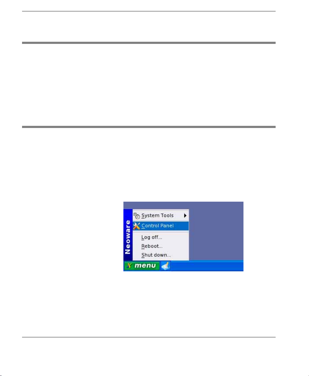
1 Click on the
12 Network Configuration
menu
button in the taskbar at the bottom of the
display and select
Control Panel - Main window will be displayed.
The
Control Panel in the menu.
Page 27
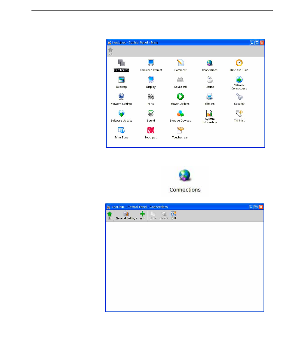
2 Double-click on the Connections icon.
Getting Started
Creating a New Connection 13
Page 28
Getting Started
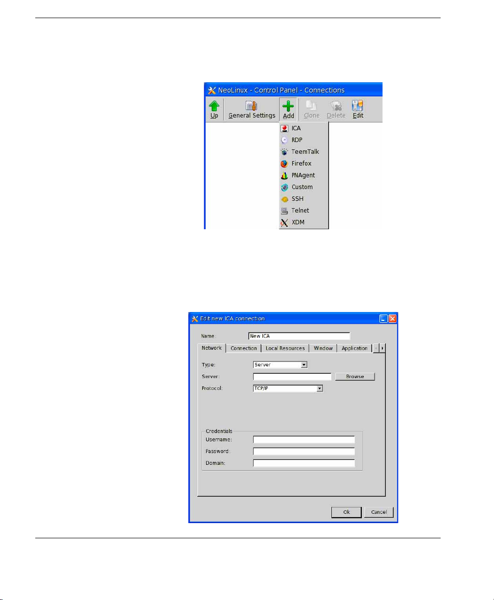
3 Click the Add icon in the toolbar and select the type of connec-
tion you want to create from the drop-down menu.
An
Edit new connection dialog will be displayed for the chosen
connection type.
4 In the Edit new connection dialog, enter a descriptive name for
the connection in the
Name field at the top. This will be used to
identify the connection to the user.
14 Creating a New Connection
Page 29
Getting Started
5 Specify the network settings required to make a connection.
6 Click on the tab titles along the top of the dialog to access
additional setup options that you may wish to configure. Refer
to the sections for each dialog tab in the relevant "Connection
Configuration" chapter for details of all the options available.
7 When you have finished configuring the connection, click OK.
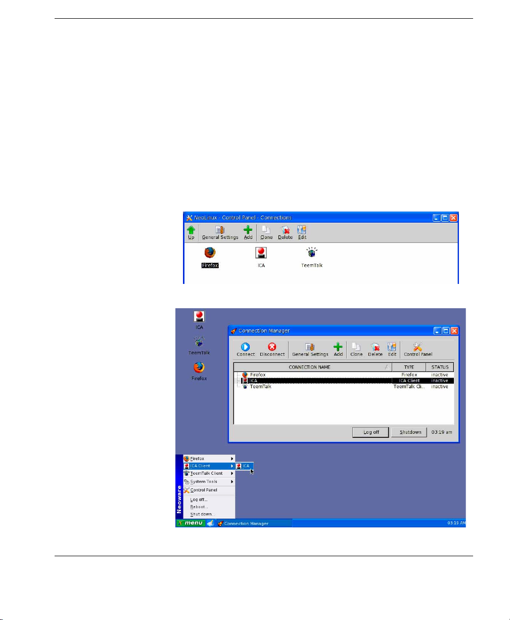
An icon for the new connection will be displayed in the
Panel - Connections
listed for selection in the taskbar
Manager
, which is described in the following sections.
window and on the desktop, and it will be
menu
and the Connection
Control
Creating a New Connection 15
Page 30
Getting Started
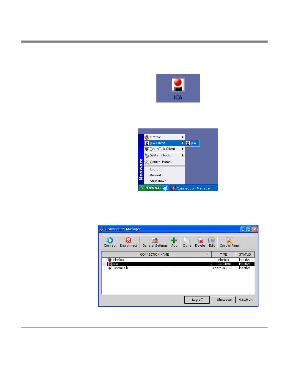
Starting a Connection
There are several ways of starting a predefined connection:
• Double-click on the connection icon displayed on the desktop.
• Click on
menu
in the taskbar and select the name of the connec-
tion at the top of the menu.
• Click on
tion Manager
menu
in the taskbar and select System Tools > Connec-
. Select the connection name then click the Connect
icon in the toolbar.
16 Starting a Connection
Page 31

Using the Connection Manager
The Connection Manager provides access to all your connection
configurations and enables you to create new connections. It also
includes options for editing, cloning, and deleting connections, and
accessing the
access to these options by setting a password (see “Security” on
page 20).
Control Panel, though you can prevent unauthorised
Getting Started
Displaying the Connection Manager
To display the Connection Manager, click on
and select
System Tools > Connection Manager.
menu
in the taskbar
Note that if Kiosk mode is enabled (see “Kiosk Mode” on page 19)
the
Connection Manager will be displayed on the desktop already.
Making a Connection
To make a connection, select the name of the connection in the list
of connections then click the
nect, select the connection name then click
Connect icon in the toolbar. To discon-
Disconnect.
Using the Connection Manager 17
Page 32

Getting Started
Toolbar Options
Connect Starts the selected connection.
Disconnect Disconnects the selected connection.
General Settings Displays a menu of connection types for which
you can specify settings that will apply to all
connections of a particular type.
Add Displays a menu of connection types enabling you
to create a new connection. Select the type of
connection you want to add from the menu to
display the
Clone Creates an exact copy of the selected connection.
Edit new connection dialog.
The copy will have the same name as the source
but preceded by Copy of.
Delete Deletes the selected connection.
Edit Displays the Edit connection dialog for the
selected connection, allowing you to change
settings.
Control Panel Displays the Control Panel - Main window.
Logging Off & Shutting Down
The Connection Manager includes buttons to enable you to Log off
Shutdown the thin client. Clicking either of these buttons will
or
display a message box warning you that any active applications will
be closed. Click
18 Using the Connection Manager
OK if you want to continue.
Page 33

Kiosk Mode
Getting Started
Kiosk mode presents a limited set of options to the user. The desktop
will display the
Connection Manager but no taskbar,
menu
, or con-
nection icons. You can prevent access to all toolbar features except
Connect and Disconnect by setting a password as described in the
section “Security” on page 20.
Enabling Kiosk Mode
To enable kiosk mode:
1 Click on
2 Double-click on the Desktop icon in the Control Panel - Main
menu
in the taskbar and select Control Panel.
window.
3 Select the option Enable kiosk mode on the Desktop settings tab
Desktop dialog (displayed by default) and click Apply
of the
OK.
then
Kiosk Mode 19
Page 34

Getting Started
Security
You can prevent unauthorised access to system settings by specifying a password. Once set, you will need to enter the password in
order to access the
Prompt.
The
Administrator password dialog will be displayed by default
Control Panel, Registry Editor and the Command
each time a password is required. However, you can configure it so
that you only need to supply the password once by checking the
Don’t ask again until Log off check box. This will cause your pass-
word to be remembered and prevent the dialog from being displayed
again until you log off.
Setting a Password To set a password:
1 Click on
2 Double-click on the Security icon.
menu
20 Security
in the taskbar and select Control Panel.
Page 35

Getting Started
3 Click the Change button to display the Admin password dialog.
4 Enter the password you want to use in the Password field, then
confirm it by typing it again in the
OK to continue.
Click
5 Click Apply then OK to make the password active.
Confirm password field.
Security 21
Page 36

Getting Started
Menu Options
Displaying the Menu
Connection Selection
Clicking the green
menu
button on the taskbar will display a menu
that provides access to various functions and system settings.
The
menu
can also be displayed using a keyboard shortcut (default
Shift + Esc). Refer to the section “Keyboard Shortcuts” on page 240
for details.
The top of the
menu
will list the names of any connections that have
been defined. Selecting a connection name in the menu will start that
connection.
22 Menu Options
Page 37

Getting Started
System Tools Selecting the System Tools item will list programs for selection.
Software Update
This enables you to update the features supported by your thin client.
Refer to the section “Software Update” on page 274 for details.
Connection Manager
The Connection Manager provides access to all your connection
configurations and enables you to create new connections. It also
includes options for editing, cloning, and deleting connections, and
accessing the
Control Panel. Refer to the section see “Using the
Connection Manager” on page 17 for details.
Network Connections
This displays a dialog enabling you to select the type of network
connection to use. For information on specifying network settings,
refer to the section “Network Configuration” on page 37.
Menu Options 23
Page 38

Getting Started
Registry Editor
The Registry is a database used by NeoLinux to store configuration
information. Some of the information in this database can be set
using the
Control Panel, which provides a graphical interface suit-
able for general users.
The
Registry Editor enables system administrators to have complete
control of the thin client configuration, and includes features such as
the ability to prevent the user from changing specific settings. Refer
to the section “The Registry Editor” on page 283 for details.
Note that a password is required to view the
Registry Editor. Refer
to the section “Security” on page 20 for details on how to set a password.
Factory Reset
This enables you to reset the entire system to the state it was in when
the thin client was powered-on for the very first time. Note that you
will lose all connection configurations as well. A message will be
displayed warning you that the thin client will restart and reset to
factory defaults. Click the
ahead, or
Cancel.
Factory Reset button if you want to go
If a password has been set, you will need to enter the password
before you can perform a factory reset.
24 Menu Options
You can reset the password by clicking the
Reset Password button
to display a reset code, then contacting Neoware Technical Support
Page 39

Getting Started
and giving them the reset code. They will then provide you with a
reset key which you need to enter in the
Command Prompt
Enter reset key field.
The Command Prompt displays a VT102 terminal emulator window
so you can enter system commands directly. Refer to the section
“Command Prompt” on page 270 for details.
Note that a password is required to view the
Command Prompt.
Refer to the section “Security” on page 20 for details on how to set a
password.
Change Screensaver Password
This item will only be displayed when screen saver is enabled and
the option
Screensaver tab in the Desktop dialog. (Refer to the section “The
Users may set a screen saver password is selected on the
Screensaver Tab” on page 218 for details.)
Menu Options 25
Page 40

Getting Started
Selecting
Change Screensaver Password will display a dialog
enabling a password to be set.
If a password is set by the user, once the screen saver is activated,
any input by a user will cause the display to request the password in
order to deactivate the screen saver.
Note: An administrator can also use the password set using the
Security
System Info
dialog to deactivate the screen saver.
This displays information about your thin client and its operating
system. Refer to the section “Displaying System Information” on
page 35 for details.
Control Panel The Control Panel provides access to a user-friendly graphical
interface that enables you to change system settings and define
connections.
26 Menu Options
Page 41

Getting Started
Logging Off The Log off option on the
cations. A message box will be displayed asking you to confirm the
action.
Rebooting the System
The Reboot option on the
operating system shut down then restart. Note that all active connections will be closed. A message box will be displayed asking you to
confirm the action.
Shutting Down Your Thin Client
The Shutdown option on the
thin client. All active connections will be closed. A message box
will be displayed asking you to confirm the action.
menu
enables you to close all active appli-
menu
enables you to make the thin client
menu
enables you to shutdown your
Menu Options 27
Page 42

Getting Started
Keyboard Shortcuts
A variety of keyboard shortcuts are provided to enable you to
quickly access or action items on the desktop:
• Display the
• Switch to next connection: Ctrl + Alt + Ta b
• Next window: Ctrl + Alt + Up
• Previous window: Ctrl + Alt + Down
• Minimize window: Ctrl + F12
• Minimize all windows: Ctrl + Alt + End
• Close active window: Ctrl + Alt + F4
• Command prompt: Ctrl + Alt + X
• Run screen saver: Ctrl + Alt + L
• Display system info: Ctrl + Alt + I
menu
: Shift + Esc
You can change the default keyboard shortcuts and define your own
using the
Panel
Keyboard dialog which is displayed from the Control
. Refer to the section “Keyboard Shortcuts” on page 240 for
details.
Menu Item Selection If a menu item includes an underlined character, press that key on
the keyboard together with the Shift key to highlight the menu item.
You can then press the Return key to select or action the item.
Using the Keyboard to Navigate the Display
On the desktop, in menus and windows, pressing the Up, Down,
Left or Right arrow keys will cause the next or previous item on the
display to be selected, depending on which key was pressed. Pressing the Return key will action the selection.
In a dialog, if it displays two or more tabs of setup options, pressing
the Left or Right arrow keys will allow you to select the required
28 Keyboard Shortcuts
Page 43

Getting Started
tab. To access options on the dialog tab, press the Ta b key until the
option you want to change is selected. The selection will move from
top to bottom and left to right, followed by the
OK, Apply and Cancel
buttons (if present), then back to the tab headings.
Changing Settings To change the state of a check box, press the Spacebar to toggle
between checked and unchecked.
To make a selection from a list box, use the Up or Down arrow keys.
Using the Desktop
The desktop is the main NeoLinux display or workspace where you
can display program windows. There are a variety of controls you
can use to manage the windows on your display, and you can change
the display to suit your requirements. For a complete description of
how to use the desktop, refer to the section “Using The Desktop” on
page 193.
Setting the Date, Time & Time Zone
It is important that your thin client is configured with the correct
date and time as these settings will be used whenever you save files.
The time will also be displayed on the task bar.
There are two dialogs where date and time settings are specified:
Date and Time and Time Zone. Both are displayed from the Control
.
Panel
Date and Time To specify the date and time:
1 Click on
menu
in the taskbar and select Control Panel.
Using the Desktop 29
Page 44

Getting Started
2 Double-click on the Date and Time icon.
The
Date is specified by selecting the month and year from the list
boxes then clicking on the day in the table. The days are displayed in
the order Monday to Sunday by default. You can change the order to
Sunday to Saturday by checking the
Time is specified using the numeric list box. To change the time,
The
double-click on the hour, minutes or seconds (or am/pm) then click
the up or down arrow buttons. The graphical clock display will
change accordingly. You can select either
by default), or 24 hour (when unchecked).
30 Setting the Date, Time & Time Zone
Start on Sunday box.
12 hour format (checked
Page 45

Getting Started
Time Zone You can set the time zone by double-clicking the Time Zone icon in
the
Control Panel.
Sound Settings
Make sure the
Time zone setting matches your location.
When sound is enabled, you can adjust its volume and enable two or
more sounds issued at the same time to be mixed instead of played
one after the other.
To specify sound settings:
1 Click on
2 Double-click on the Sound icon.
menu
in the taskbar and select Control Panel.
Sound Settings 31
Page 46

Getting Started
32 Sound Settings
Sound is enabled by default. To disable sound, uncheck the
checkbox. The Volume slider enables you to adjust the vol-
sound
Enable
ume level. If you want the volume level to be saved when the thin
client is rebooted, check the
Selecting the
to quickly access the
Show mixer applet in taskbar option will enable you
Volume slider by clicking on a Sound icon in
Save volume on exit checkbox.
the taskbar.
Selecting
Enable ESD (Enlightened Sound Daemon) will enable
sound from two or more sources to be mixed (for example, sound
indicating incoming message while playing music). Selecting
Enable startup sound will cause the thin client to emit a short
sequence of beeps once it has booted.
Page 47

Power Options
Getting Started
You can control the behaviour of the thin client power button so that
either the client is shutdown immediately when pressed, or it
displays a dialog asking the user to confirm shutdown. When the
Shutdown request dialog is displayed, if the user does not press the
OK or Cancel button, the thin client will shut down automatically
after a specified time period (default 60 seconds). You can also
disable the power button so that only software can shut the client
down.
To configure power settings:
1 Click on
2 Double-click on the Power Options icon.
Shutdown behaviour can have one of three settings as deter-
The
menu
in the taskbar and select Control Panel.
mined by the radio buttons:
Power Options 33
Page 48

Getting Started
Instant off The thin client is immediately powered-off when
the power button is pressed. No warning is given
if a connection is still running.
Ignore The power button is disabled. Only software can
power-off the client.
User may cancel When the power button is pressed a Shutdown
request
dialog is displayed allowing the user to
confirm or cancel. The dialog will be displayed
for the time period specified in the list box. The
default duration is 60 seconds, after which the
thin client will automatically shut down if the
user does not confirm or cancel. This feature is
useful to prevent users from having their connections still running on the server while they are
logged off.
The setting of the
Shutdown terminal if battery below checkbox
determines whether the thin client automatically powers-off when
battery power falls below a specified level (default 10%).
Managing & Updating Thin Client Software
The software installed in your thin client can be managed and
updated from a remote server using Neoware’s ezRemote Manager.
This allows an administrator to quickly update or reconfigure thin
clients connected to the network without having to leave his desk.
All the administrator has to do is install the software update snap-in
from Neoware onto the server running ezRemote Manager, then use
the
Snap-in Manager to update selected thin clients. Please refer to
the Neoware ezRemote Manager User Manual for detailed instructions.
You can also update software on your thin client using the
Update facility as described in the chapter “Updating Your Thin Cli-
ent Software” on page 273. Note that you can only update the thin
client on which you are running
Software
Software Update using this method.
34 Managing & Updating Thin Client Software
Page 49

Displaying System Information
You can display information about your thin client and its system
software either by pressing the keys Ctrl + Alt + i (default keyboard
shortcut), or by selecting
menu
:
Getting Started
System Tools > System Info from the
or by double-clicking the
:
Panel
The
System Info dialog consists of three tabs:
General tab provides information about the operating system
The
System Information icon in the Control
version, CPU, system and board, including the serial number. It also
shows the amount of Flash memory and RAM available in your thin
client and how much is used.
The
Network tab displays information about your thin client’s net-
work configuration. The MAC address is also displayed here.
Net Tools tab enables you to perform various operations to test
The
your network and discover IP addresses or hostnames.
Refer to the section “System Information” on page 277 for more
information.
Displaying System Information 35
Page 50

Getting Started
Boot Options
The way NeoLinux is loaded and displayed can be changed at boot
time by pressing the Esc key within two seconds after you have
powered-on or rebooted the thin client. A Boot menu will be displayed allowing you to select one of four options:
• NeoLinux - will run NeoLinux as normal.
• NeoLinux Safe VGA - will run NeoLinux using a generic video
driver (VESA). This is useful when an incorrect display resolution has been set and you need to reconfigure the system.
• NeoLinux Console Only - will run NeoLinux without the graph-
ical interface. The user will be prompted to enter their user name
and password. Use root and your security password.
• NeoLinux Debug - will run NeoLinux with messages during the
boot process.
Use the Up and Down cursor keys to select the option your require
then press Enter. Depending on the option you select, you may have
further options that require keyboard input. The screen will display
instructions on how to proceed.
36 Boot Options
Page 51

Introduction
NeoLinux Thin Client User Manual
CHAPTER 4 Network
Configuration
This chapter describes how to configure the thin client for connection to your network.
Your thin client must be assigned a unique Internet Protocol (IP)
address in order to communicate on your network. Your network
may also require other settings.
If your network uses a remote configuration service such as DHCP
(Dynamic Host Configuration Protocol), the thin client will automatically configure itself for the network when you switch it on.
DHCP provides the settings that the thin client must use to communicate on the network.
If your network does not use DHCP, or you need to enter network
settings manually, use the dialogs displayed from the
-
Network Connections window, or the Network Settings dialog
for general settings, as described in the following sections.
Control Panel
37
Page 52

Network Configuration
Displaying the Network Connections Window
1 Click on
2 Double-click on the Network Connections icon to display the
Control Panel - Network Connections window.
menu
in the taskbar and select Control Panel.
Note: The
On-board Wifi
icon will only be displayed if your thin
client supports wireless connections.
38 Displaying the Network Connections Window
Page 53

On-board LAN
Network Configuration
You can specify LAN settings for your thin client using the Ethernet
"On-board lan"
board Lan
dialog. This is displayed by double-clicking the On-
icon in the Control Panel - Network Connections
window.
The
Ethernet "On-board lan" dialog consists of two tabs of setup
options which are accessed by clicking on the tab titles along the top.
The following sections describe the options available on each tab.
On-board LAN 39
Page 54

Network Configuration
Name
Default: On-board lan
This field enables you to enter a descriptive name for this LAN
configuration. The name will be used to identify the network
configuration to the user.
Link type
Default: autosense
This specifies the speed (10 or 100 MB) and mode (Half or Full
duplex) of the network card. Selecting autosense will enable the thin
client to automatically detect the best speed and mode.
Autostart
Default: Checked
This determines whether this network connection is automatically
started when the thin client is powered-on or rebooted.
The IP Settings Tab Enable DHCP
Default: Checked
40 On-board LAN
The setting of this option determines how the thin client obtains network configuration settings.
When DHCP is enabled, the thin client will rely on a remote DHCP
configuration service to supply the required settings. These settings
are then saved in the thin client. At the next client bootup, if the
client cannot reach the DHCP server, the client will connect to the
network using the saved network information provided that the
initial lease time has not expired.
Unchecking this box will disable remote network configuration and
cause the thin client to use the network settings specified in the
following dialog options. You will need to ask your network
administrator for the entries required.
Page 55

Network Configuration
IP address
When DHCP is disabled, this enables you to specify a static IP
address for the thin client. This must be entered in a dotted-decimal
format (for example: 10.10.10.10).
Subnet mask
When DHCP is disabled, this enables you to specify a subnet mask,
if required. A subnet mask distinguishes your local network from a
larger network. This must be entered in a dotted-decimal format (for
example: 255.0.0.0).
Default gateway
When DHCP is disabled, this enables you to specify the IP address
of the router or gateway computer that connects your local network
to other networks that contain servers which your thin client may
need to access. The entry must be in dotted-decimal format.
DNS Servers
When DHCP is disabled, this enables you to specify the IP addresses
of DNS servers to use. Domain Name Service (DNS) is a serverbased program that translates text-based server names into IP
addresses.
To enter a DNS server address, click the
The
Add a new element dialog will be displayed.
New button:
Entering the address of the DNS server in dotted-decimal format
then click
OK. The address to be listed in the Address field.
On-board LAN 41
Page 56

Network Configuration
The DHCP Options Tab
To edit a DNS server address, select the address in the
Address
field then click the Edit button.
To delete a DNS server address, select the address in the
Address
prompted to confirm the deletion by clicking
field then click the Delete button. You will be
OK.
42 On-board LAN
Send dhcp user class
Default: Unchecked
When this option is checked, the DHCP client will send the DHCP
option 77 (USERCLASS) to the DHCP server. This option can be
used by the DHCP server to classify the client. For example, if the
Page 57

Network Configuration
client has the userclass wlan, the server could set another management group.
Send custom class
Default: Unchecked
If no custom class is specified, the type of connection is sent as
default (i.e. ethernet for "On-board lan").
On-board LAN 43
Page 58

Network Configuration
On-board WiFi
If your thin client supports Wifi, you can configure it for a wireless
connection using the
by double-clicking the
Network Connections window.
The
Wlan "On-board Wifi" dialog consists of several tabs of setup
Wlan "On-board Wifi" dialog. This is displayed
On-board Wifi icon in the Control Panel -
options which are accessed by clicking on the tab titles along the top.
The following sections describe the options available on each tab.
Name
Default: On-board Wifi
This field enables you to enter a descriptive name for this Wireless
LAN configuration. The name will be used to identify the network
configuration to the user.
44 On-board WiFi
Page 59

The Wireless Tab
Network Configuration
SSID
Default: Any
Enter the ID of the access point you want to connect to in this field.
Nick Name
Default: myterminal
You can enter a name to identify the connection here.
On-board WiFi 45
Page 60

Network Configuration
Operating Mode
Default: Managed (with access point or with roaming)
This should not be changed from the default setting, which allows
multiple connections.
Protocol
Default: Auto
This specifies the access point transmission speed and frequency
range. Depending on the access point, selecting Auto will cause it to
automatically detect the type of device and adjust the transmission
and frequency range accordingly.
Channel
Default: automatic
This enables you to specify the radio frequency which should be
used by the access point and the wireless adapter. The default auto-
matic setting usually works by automatically selecting the best
channel to use. However, you can use a specific frequency by selecting one of the channels 1 through 14 as listed in the following table:
46 On-board WiFi
1 2,412 USA FCC, Europe ETSI, Japan
2 2,417 USA FCC, Europe ETSI, Japan
3 2,422 USA FCC, Europe ETSI, Japan
4 2,427 USA FCC, Europe ETSI, Japan
5 2,432 USA FCC, Europe ETSI, Japan
6 2,437 USA FCC, Europe ETSI, Japan
7 2,442 USA FCC, Europe ETSI, Japan
8 2,447 USA FCC, Europe ETSI, Japan
9 2,452 USA FCC, Europe ETSI, Japan
10 2,457 USA FCC, Europe ETSI, Japan
11 2,462 USA FCC, Europe ETSI, Japan
12 2,467 Europe ETSI, Japan
13 2,472 Europe ETSI, Japan
14 2,484 Japan
Page 61

The Security Tab
Network Configuration
Authentication
Default: Plain text or WEP
Specifies the type of authentication required by the access point.
When Plain text or WEP is selected you can enter one or more
encryption keys in the fields at the bottom of the dialog.
Selecting one of the WPA-Personal Enterprise (EAP) settings will
enable the EAP authentification options.
On-board WiFi 47
Page 62

Network Configuration
Encryption
Default: None
When
Authentication is set to Plain text or WEP, selecting WEP
will enable encryption.
When WEP is selected, the field on the right allows you to select
either Open System for no security checking, or Shared Key which
requires the thin client and access point to use the same WEP key to
authenticate.
PSK
Default: Unspecified
You can enter a pre-shared key in this field when
Authentication is
set to WPA-PSK or WPA2-PSK.
EAP authentification
These options are only available when the Authentication field is set
to one of the WPA-Personal Enterprise (EAP) settings.
encryption keys
When the Authentication field is set to Plain text or WEP, you can
enter one or more encryption keys in these fields.
48 On-board WiFi
Page 63

The Network Tab
Network Configuration
Enable DHCP
Default: Checked
The setting of this option determines how the thin client obtains network configuration settings.
When DHCP is enabled, the thin client will rely on a remote DHCP
configuration service to supply the required settings. These settings
are then saved in the thin client. At the next client bootup, if the
client cannot reach the DHCP server, the client will connect to the
network using the saved network information provided that the
initial lease time has not expired.
On-board WiFi 49
Page 64

Network Configuration
Unchecking this box will disable remote network configuration and
cause the thin client to use the network settings specified in the
following dialog options. You will need to ask your network
administrator for the entries required.
IP address
When DHCP is disabled, this enables you to specify a static IP
address for the thin client. This must be entered in a dotted-decimal
format (for example: 10.10.10.10).
Subnet mask
When DHCP is disabled, this enables you to specify a subnet mask,
if required. A subnet mask distinguishes your local network from a
larger network. This must be entered in a dotted-decimal format (for
example: 255.0.0.0).
Default gateway
When DHCP is disabled, this enables you to specify the IP address
of the router or gateway computer that connects your local network
to other networks that contain servers which your thin client may
need to access. The entry must be in dotted-decimal format.
50 On-board WiFi
DNS Servers
When DHCP is disabled, this enables you to specify the IP addresses
of DNS servers to use. Domain Name Service (DNS) is a serverbased program that translates text-based server names into IP
addresses.
To enter a DNS server address, click the
New button:
Page 65

Network Configuration
Add a new element dialog will be displayed.
The
Entering the address of the DNS server in dotted-decimal format
then click
OK. The address to be listed in the Address field.
To edit a DNS server address, select the address in the
Address
field then click the Edit button.
To delete a DNS server address, select the address in the
Address
prompted to confirm the deletion by clicking
field then click the Delete button. You will be
OK.
On-board WiFi 51
Page 66

Network Configuration
The DHCP Options Tab
52 On-board WiFi
Send dhcp user class
Default: Unchecked
When this option is checked, the DHCP client will send the DHCP
option 77 (USERCLASS) to the DHCP server. This option can be
used by the DHCP server to classify the client. For example, if the
client has the userclass wlan, the server could set another management group.
Send custom class
Default: Unchecked
If no custom class is specified, the type of connection is sent as
default (i.e. wlan for "On board Wifi").
Page 67

General Network Settings
General network settings can be specified by double-clicking the
Network Settings
The
Network Settings dialog consists of two tabs of setup options
which are accessed by clicking on the tab titles along the top. The
following sections describe the options available on each tab.
The General Tab
Network Configuration
icon in the Control Panel - Main window.
General Network Settings 53
Page 68

Network Configuration
Hostname
This field enables you to specify the hostname to use instead of the
one generated by default.
Domain name
This field enables you to specify the domain name to use instead of
the one provided by DHCP.
Time Server (NTP)
A time server is used to synchronise the terminal clock with an NTP
date server. The name or IP address of the time server can be specified in this field.
Enable gratuitous ARP
Default: Checked
When checked, the thin client will launch an ARP broadcast over the
network. This is sometimes used to update switch and router.
ARP timeout
Default: 300
This determines the timeout between each ARP request.
DHCP retries
Default: 3
This specifies how many times DHCP broadcasts.
DHCP timeout
Default: 7
This determines the timeout between each DHCP request. The
DHCP will fail after the last retry timeout.
Check for duplicate IP address
Default: Checked
This is used to check whether a device on the network is already
using the static IP address you have chosen for your thin client, or
54 General Network Settings
Page 69

The Hosts Tab
Network Configuration
whether another device has tried to use the same IP address as your
thin client.
Socket test timeout
Default: 5
This is a global timeout for an internal socket test program, which is
used to test font server validity for example.
This enables you to add host names to /etc/hosts permanently. To
enter a new static host IP address and name(s), click the
Add a new element dialog will be displayed.
The
New button:
General Network Settings 55
Page 70

Network Configuration
Entering the IP address and name(s) of the host then clicking
cause the supplied details to be listed in the
Static hosts field.
To edit static host details, select the address then click the
Edit button.
To delete a static host address, select the address then
click the
the deletion by clicking
Delete button. You will be prompted to confirm
OK.
OK will
56 General Network Settings
Page 71

Introduction
NeoLinux Thin Client User Manual
CHAPTER 5 ICA Connection
Configuration
This chapter describes how to create an ICA connection and
explains the configuration options available.
This manual is intended to cover a number of Neoware thin client
models. Depending on the software version included with your thin
client, it may not have the ICA client installed.
ICA (“Independent Computing Architecture”) is a network protocol created by Citrix Systems, Inc. and used by Windows-based
servers running Citrix MetaFrame or WinFrame. This chapter
describes how to create a new ICA connection, then proceeds to
explain all the configuration options available. For details on how
to start an ICA connection, refer to the section “Starting a Connection” on page 16.
57
Page 72

ICA Connection Configuration
Creating a New ICA Connection
This section describes the basic procedure for creating a new ICA
connection. Descriptions of all the options available are provided
later in this chapter.
1 Click on
2 Double-click on the Connections icon to display the Control
Panel - Connections
menu
in the taskbar and select Control Panel.
window.
3 Click the Add icon in the toolbar and select ICA from the drop-
down menu to display the
58 Creating a New ICA Connection
Edit new ICA connection dialog.
Page 73

ICA Connection Configuration
Creating a New ICA Connection 59
Page 74

ICA Connection Configuration
4 In the Name field at the top of the dialog, enter a descriptive
5 In the Type list box on the Network tab, select the type of ICA
6 In the Server field, depending on the Type setting, specify the
7 Select the network protocol to use from the Protocol list: TCP/
name for the ICA connection. This will be used to identify the
connection to the user.
connection required: Server or Published Application.
name or IP address of the server, or the name of the published
application. A list of available servers or publications may be
displayed for you to select from, or you can type in the details.
If ICA browsing is required across a router, or you need to specify additional primary Citrix servers, refer to the section “The
Server Location Tab” on page 73 for details.
IP, TCP/IP + HTTPS server location, or SSL/TLS + HTTP
server location. Selecting Use Default will use the setting spec-
ified in the
If the
ICA general settings dialog.
Server field did not provide a listing of available servers
or published applications, and you are using MetaFrame with
browsing enabled, you will need to set the network protocol to
TCP/IP instead of TCP/IP + HTTP server location.
Note: If your servers can only respond to TCP/IP browser
requests, you should consider setting the global default network
protocol to TCP/IP in the
the section “The Server Location Tab” on page 86 for details.
8 If you want an application to be automatically run once you have
logged into an ICA connection, click on the
specify the path and application name in the
(for example: C:\WTSVR\Notepad.exe), and the drive and path
of its working directory in the
example: C:\My Documents).
Note that the specified application will be the only one available
to the user during this connection.
60 Creating a New ICA Connection
ICA general settings dialog. Refer to
Application tab
Application field
Working Directory field (for
Page 75

ICA Connection Configuration
9 If you want to enable auto login, specify the Username and
Password. If the user authenticates against an NT-domain, you
need to specify the name of the domain in the
Domain field.
If you do not specify any required login information here, the
user will be prompted for it when the connection is started.
10 Click on the tabs along the top of the dialog to access additional
setup options that you may wish to configure. Refer to the sections for each dialog tab later in this chapter for details of all the
options available.
11 When you have finished configuring the ICA connection, click
OK.
An icon for the new ICA connection configuration will be
displayed in the
desktop, and it will be listed for selection in the taskbar
and the
Connection Manager.
Control Panel - Connections window and on the
menu
If you need to change the configuration of an ICA connection, display the
Control Panel - Connections window then double-click on
the relevant ICA connection configuration icon.
Creating a New ICA Connection 61
Page 76

ICA Connection Configuration
The Edit New ICA Connection Dialog
This section describes all the options available in the Edit new ICA
connection
options which are accessed by clicking on the tab titles along the top.
Name
Default: New ICA
This field enables you to enter a descriptive name for the ICA connection. The name will be used to identify the connection to the user.
The Network Tab
dialog. The dialog consists of several tabs of setup
62 The Edit New ICA Connection Dialog
Page 77

ICA Connection Configuration
Type
Default: Server
This specifies whether the ICA connection is to connect to a server
or to a published application.
Server
Depending on the Type setting, this enables you to specify the name
or IP address of the server, or the name of the published application.
A list of available servers or publications may be displayed for you
to select from, or you can type in the details.
Protocol
Default: TCP/IP
This setting determines the way server browsing is performed. TCP/
IP is preferred for MetaFrame 1.8 and older. TCP/IP + HTTP
server location is preferred for Metaframe XP.
Selecting Use Default will use the protocol setting determined by
the
Protocol option in the ICA general settings dialog.
If the
Server field did not provide a listing of available servers or
published applications, and you are using MetaFrame with browsing
enabled, you will need to set the network protocol to TCP/IP instead
of TCP/IP + HTTP server location.
Select SSL/TLS + HTTPS server location when using the ICA client over the Internet or through a firewall or proxy server. The client
will use the HTTPS protocol to search for a list of MetaFrame XP
Presentation Servers. The client communicates with the MetaFrame
XP Presentation Server using ICA with SSL/TLS. SSL/TLS +
HTTPS provides strong encryption of ICA traffic and MetaFrame
XP Presentation Server authentication.
Username, Password & Domain
Entering a Username or Password here will enable the user to
access the connection without having to enter login details. If you
work within a domain, the
Domain field enables you to specify the
domain name.
The Edit New ICA Connection Dialog 63
Page 78

ICA Connection Configuration
The Connection Tab
Encryption level
Default: Basic
This determines the level of encryption applied to transmitted data.
Mouse click feedback
Default: Automatic
When using a slow connection, performance can be improved by
selecting Automatic or Enabled. This will enable mouse clicks to
be confirmed locally by the ICA protocol, instead of waiting for the
server to echo the mouse clicks back to the thin client.
64 The Edit New ICA Connection Dialog
Page 79

ICA Connection Configuration
Local text echo
Default: Automatic
When using a slow connection, performance can be improved by
selecting Automatic or Enabled. This will enable keyboard entries
to be confirmed locally by the ICA protocol, instead of waiting for
the server to echo the keystrokes back to the thin client.
Data compression
Default: Unchecked
Data compression should be enabled for narrow banded transmission lines.
Use bitmap cache
Default: Unchecked
Selecting this option will cause bitmap data to be stored in local thin
client memory once downloaded from the server. This will enable
the thin client to display previously viewed graphics faster as it does
not have to wait for the server to send the data again.
The Edit New ICA Connection Dialog 65
Page 80

ICA Connection Configuration
The Local Resources Tab
Sound
Default: Disabled
The sound level for this connection can be specified by selecting
either Disabled, High quality, Medium quality, or Low quality.
Enable drive mapping
Default: Unchecked
If you have an external USB storage device attached to your thin
client and it has been configured in the
be used in the ICA connection, these options enable you to map the
storage device to a different drive letter in the ICA connection. Note
that the letter A is commonly used for a floppy drive, and C for a
hard disk.
66 The Edit New ICA Connection Dialog
Control Panel so that it can
Page 81

Auto printer creation
Default: Checked
ICA Connection Configuration
If you have a line printer defined in the
Control Panel, selecting this
option will enable that printer to be created and used by the ICA
connection. Note that the Windows printer driver name must be
specified so that the correct driver is used.
The Edit New ICA Connection Dialog 67
Page 82

ICA Connection Configuration
The Window Tab
Window size
Default: Fullscreen
The default size of the ICA connection window can be defined without restriction. The window size can be specified in pixels, percentage of screen size, or full screen.
When Use Default is selected, the window size is determined by the
setting of the
Window size option in the ICA general settings dialog.
When Fixed Size is selected, the window size is specified by the
Width and Height settings.
When Percentage of screen size is selected, the window size is
specified by the
Screen setting.
68 The Edit New ICA Connection Dialog
Page 83

ICA Connection Configuration
When Fullscreen is selected, the entire display is used by the ICA
connection.
Window Colors
Default: Automatic
The setting of the
Window Colors option determines the number of
colours that can be displayed.
When Use Default is selected, the window colors are determined by
the setting of the
Window Colors option in the ICA general settings
dialog.
Selecting Automatic will cause NeoLinux to automatically use the
appropriate color setting. When set to 256 colors, the setting of the
256 color mapping option determines whether the exact colors are
used, or approximate colors.
The Edit New ICA Connection Dialog 69
Page 84

ICA Connection Configuration
The Application Tab
The options on this tab enable you to specify an application for the
thin client to automatically run on when the ICA connection starts.
Note that the connection will be reserved exclusively for this application.
Application
This field enables you to specify the name of an application that the
thin client will automatically run once you have logged into an ICA
connection. You must enter the full path and filename of the application, for example: C:\WTSVR\Notepad.exe. Note that the specified
application will be the only one available to the user during this connection.
70 The Edit New ICA Connection Dialog
Page 85

ICA Connection Configuration
Working directory
The drive and path of the working directory is specified in this field.
For example: C:\My Documents. The path must exactly match the
one on the ICA server.
The Edit New ICA Connection Dialog 71
Page 86

ICA Connection Configuration
The Firewall Tab
The options in this dialog should only be used if a firewall exists
between the thin client and the ICA server or published applications.
Type
Default: None (Direct)
To establish a direct connection between an ICA connection and an
ICA server across a firewall, select either Secure (HTTPS) or
Socks, then specify the
of the
Port to use. Selecting Default will use the setting determined
by the
Proxy Host
Firewall tab Type option in the ICA general settings dialog.
When Type is set to Secure (HTTPS) or Socks, you can specify the
Address of the proxy server and the number of the Port to use
(default 1080).
72 The Edit New ICA Connection Dialog
Address of the proxy server and the number
Page 87

The Server Location Tab
ICA Connection Configuration
This tab enables you to define a list of primary Citrix browser
servers that can be accessed to determine the list of available ICA
connections (desktops and/or published applications).
Use default
Default: Unchecked
This determines whether the default
ICA general settings are used
for the server location, or the settings specifed in this dialog.
TCP Address
Address entries in this field are only realized if one or more ICA
servers are behind a router. This is because the server browsing
offered by the ICA protocol does not work across a router. You can
The Edit New ICA Connection Dialog 73
Page 88

ICA Connection Configuration
enter the name of a server so that the thin client can offer a list of
available ICA servers and applications.
To enter a new TCP address, click the
Add a new element dialog will be displayed.
The
Entering a TCP/IP address then clicking
to be listed in the
TCP Address field.
To edit a TCP/IP address, select the address in the
Address
field then click the Edit button.
To delete a TCP/IP address, select the address in the
Address field then click the Delete button. You will be
prompted to confirm the deletion by clicking
HTTP Address
New button:
OK will cause that address
TCP
TCP
OK.
The http-browser-service is part of MetaFrame from Service Pack 2.
You can use HTTP-browsing as an alternative to the previous
browser services of the ICA protocol. HTTP-browser-services are
preferably used for ICA server browsing via internet. Note that they
can only be applied when Citrix XML service has been started.
The procedure for adding a new HTTP address to the
field, editing or deleting an address, is the same as described above
for the TCP/IP address.
74 The Edit New ICA Connection Dialog
HTTP Address
Page 89

The Extra Keys Tab
ICA Connection Configuration
The Extra Keys tab enables you to fine tune the ICA client by adding
key values in the ICA wfclient.ini file.
You can specify key values by clicking the
Add a new element dialog will be displayed.
The
New button:
The Edit New ICA Connection Dialog 75
Page 90

ICA Connection Configuration
Select the
Thinwire3.0), enter the
OK.
To edit a key, select the key in the
the
Section for the new key (TCP/IP, WFClient or
Name and Value of the key to set then click
Key column then click
Edit button.
To delete an key, select the key in the
click the
the deletion by clicking
Delete button. You will be prompted to confirm
OK.
Key column then
76 The Edit New ICA Connection Dialog
Page 91

The Common Settings Tab
ICA Connection Configuration
Connect via
Default: Unspecified
This specifies the type of network connection to use. You can select
from a list of network configurations currently defined in the
- Network Connections window. Note that the connection
Panel
Control
may need to wait for the network interface to be ready and a valid IP
address to be supplied (from DHCP for example) before it can start
the connection process.
Fallback Connection
Default: Unspecified
This enables you to specify an alternative connection to run if this
connection fails to connect. You can select from a list of all the con-
The Edit New ICA Connection Dialog 77
Page 92

ICA Connection Configuration
nection configurations currently defined in the
nections
Autostart Priority
window.
Control Panel - Con-
Default: Off
This enables you to specify the order in which connections are
started automatically when the client is powered-on. When set to
Off, this connection will not automatically start. Selecting a number
1 to 5 will determine the position this connection will have in the
auto start order.
Auto reconnect
Default: Unchecked
Enabling auto reconnect will cause the connection to be restarted
automatically if it is closed.
Show Icon on desktop
Default: Checked
This determines if an icon for this connection is displayed on the
desktop.
Show in Menu
Default: Checked
This determines if the name of the connection is listed in the
and
Connection Manager.
Extra environment values
Default: Unspecified
You can specify environment values by clicking the
78 The Edit New ICA Connection Dialog
menu
New button:
Page 93

ICA Connection Configuration
Add a new element dialog will be displayed.
The
Enter the
click
To edit an environment value, select the name in the
field then click the
Name and Value of the environment variable to set then
OK.
Name
Edit button.
To delete an environment value, select the name of the
environment variable in the
Delete button. You will be prompted to confirm the
deletion by clicking
OK.
Name field then click the
The Edit New ICA Connection Dialog 79
Page 94

ICA Connection Configuration
The ICA General Settings Dialog
The settings specified in the ICA general settings dialog will apply
to all ICA connections unless overridden by settings in the
nection
dialog for a specific connection.
ICA con-
To display the
icon in the Control Panel - Connections toolbar and select ICA
tings
ICA general settings dialog, click on the General Set-
from the drop-down menu.
The following sections describe all the options available in the
general settings
dialog. The dialog consists of several tabs of setup
ICA
options which are accessed by clicking on the tab titles along the top.
80 The ICA General Settings Dialog
Page 95

The Options Tab
ICA Connection Configuration
Enable Windows alert sounds
Default: Checked
This will enable or disable alert sounds that may be issued by Windows or a Windows application when it needs to warn you.
ICA acceleration (LAN only)
Default: Unchecked
Activates or deactivates the ICA acceleration for the thin client.
Allow backing store
Default: Checked
When backing store is enabled, the ICA client can use the cache of
the X-server in order to improve performance.
The ICA General Settings Dialog 81
Page 96

ICA Connection Configuration
Use server redraw
Default: Checked
Server redraw is a capability of the X-server that enables bitmaps to
be drawn (e.g. when moving windows) without slowing down the
Windows server or the network.
Disable info box before connecting
Default: Checked
This allows you to enable or disable the display of a
Connecting to...
message box when a connection is started.
Use asynchronous COM-port polling
Default: Unchecked
Selecting this option will switch the COM port to asynchronous
communication.
Allow smart card logon
Default: Unchecked
Select this option if you want to use the smart card logon capabilities
provided by Citrix.
Enable off screen surface
Default: Checked
Selecting this option will improve screen refresh by storing a copy
of the display locally in system memory. Note that this may result in
a slight decrease in system performance or a decrease in the maximum number of simultaneous connections that can be sustained.
Enable connection reuse
Default: Checked
When this option is selected, if you already have one published
application running and then you try to launch a second one, the
second published application will try to use the ICA connection
82 The ICA General Settings Dialog
Page 97

ICA Connection Configuration
established by the first application instead of creating a new ICA
connection to the server.
Minimum bitmap cache size
Default: 2048 bytes
This sets the minimum size of the bitmap cache.
The ICA General Settings Dialog 83
Page 98

ICA Connection Configuration
The Window Tab
Window size
Default: Fullscreen
The default size of the ICA connection window can be defined without restriction. The window size can be specified in pixels, percentage of screen size, or full screen.
When Fixed Size is selected, the window size is specified by the
Width and Height settings.
When Percentage of screen size is selected, the window size is
specified by the
When Fullscreen is selected, the entire display is used by the ICA
connection.
84 The ICA General Settings Dialog
Screen setting.
Page 99

Window colors
Default: Automatic
ICA Connection Configuration
The setting of the
Window colors option determines the number of
colours that can be displayed. Selecting Automatic will cause
NeoLinux to automatically use the appropriate color setting. When
set to 256 colors, the setting of the
256 color mapping option deter-
mines whether the exact colors are used, or approximate colors.
The ICA General Settings Dialog 85
Page 100

ICA Connection Configuration
The Server Location Tab
This tab enables you to define a list of primary Citrix browser
servers that can be accessed to determine the list of available ICA
connections (desktops and/or published applications).
Default protocol
Default: TCP/IP
This setting determines the way server browsing is performed. TCP/
IP is preferred for MetaFrame 1.8 and older. TCP/IP + HTTP
server location is preferred for Metaframe XP.
Select SSL/TLS + HTTPS server location when using the ICA client over the Internet or through a firewall or proxy server. The client
will use the HTTPS protocol to search for a list of MetaFrame XP
Presentation Servers. The client communicates with the MetaFrame
XP Presentation Server using ICA with SSL/TLS. SSL/TLS +
86 The ICA General Settings Dialog
 Loading...