

Page 1

MA7200 PLUS INVERTER
SERIES
FAN Quick Start Manual
1 to 2 HP
Models- MA7200 -2001/2-N1 (230V)
&
MA7200-4001/2-N1 (460V)
Rev. 1.2 – April 14th 2008
Page 2
MA7200 PLUS Inverter 1 to 2 HP Fan Quick Start Manual
_______________________________________________________________
Quick Start Guide for Fan Applications
This guide is to simplify the start up of the MA7200 PLUS Inverter series, 1 to 2 HP, for fan
applications. It is not intended to replace the MA7200 PLUS Installation and Operation Manual, and
the user is urged review this manual. There are three methods of control or combinations thereof that
that may be selected; Keypad, Analog Signal (external terminal), or Serial Communication. Only
Keypad and analog signal control will be covered as Serial Communication is beyond the scope of
this manual. For serial communication control or special external control, the user is referred to the
MA7200 PLUS Installation and Operating Manual.
SAFETY FIRST!
Step 1 - Before Starting the Inverter
• Referring to the MA7200 PLUS Instruction Manual, please review and verify that the correct
inverter size for the associated motor was received free of damage. To ensure personnel safety
and to avoid equipment damage, follow the precautions and the installation procedures for
mounting, wiring, and operating environment.
CAUTION - To avoid damage to the inverter when removing the inverter cover
and/or LCD Operator, refer to Appendix B for the proper procedure.
• In accordance with applicable codes, make electrical connections to the motor and input power
terminals. (Refer to the block diagram, Fig. 4). No other external connections should be made at
this time, as the initial control will be from the keypad.
Step 2 - Apply Power to the Drive
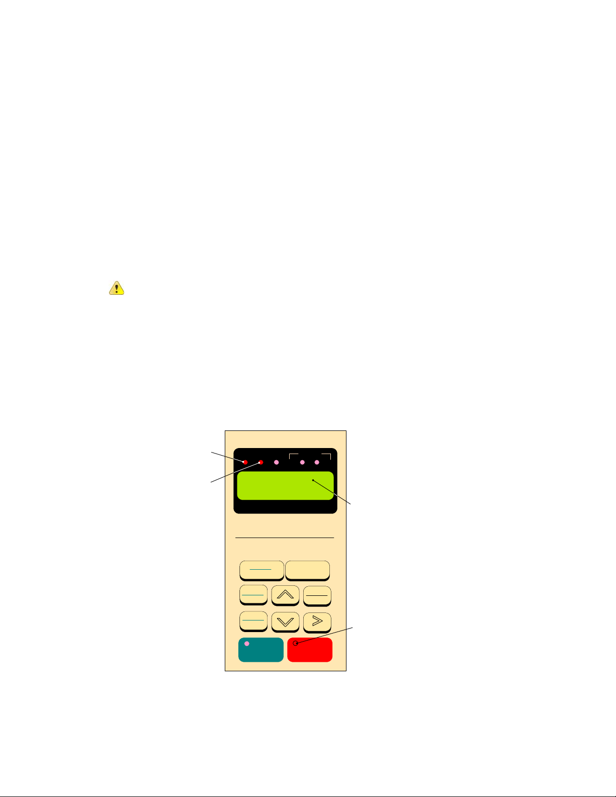
• Apply AC power to the Inverter and observe the LCD Display Line 1; it should read
“Freq. Cmd 000.00Hz”. Line 2 should read “TECO”. The red LED on the STOP key should be on.
The DRIVE and FWD LED’s should be on. (See Fig. 1 below)
LED
ON
DRIVE
FWD
REV
SEQ
REMOTE
REF
LED
ON
Freq. Cmd 000.00Hz
TECO
FLASHING
DIGITAL OPERATOR JNEP-36
PRGM
DRIVE
LOCAL
REMOTE
FWD
REV
RUN STOP
DSPL
EDIT
ENTER
RESET
LED
ON
Fig. 1 MA7200 PLUS Keypad
Step 3 - Set Drive to Run Mode
• If the red DRIVE LED is not on with AC power up, press the PGRM / DRIVE key until the red
Drive LED is on. The Inverter is now in the RUN mode.
______________________________________________________________
TECO – Westinghouse Motor Company
2
Page 3
MA7200 PLUS Inverter 1 to 2 HP Fan Quick Start Manual
_______________________________________________________________
Step 4 - Check Fan Motor Operation
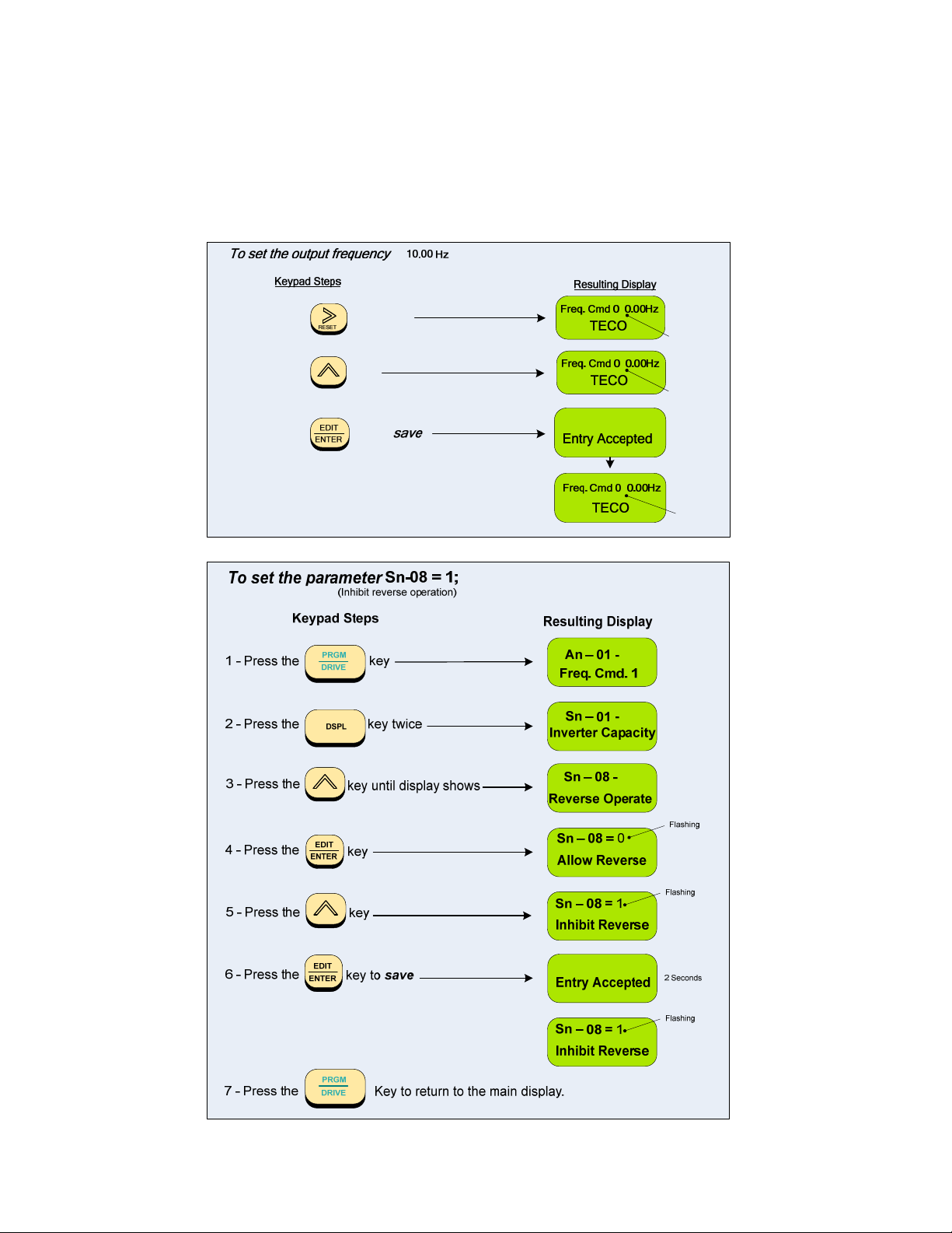
• Enter 10.00Hz for the frequency reference and set parameter Sn-08 = 1 to disable Reverse
Direction operation. Note: The output from the inverter is displayed in Hz as factory default. If
desired, the output may be displayed in per cent (%) of full speed. (see appendix)
to ;
1 - Press the
2 - Press the
3 - Press the
key twice
key
key to .
0
Flashing
1
Flashing
2 Seconds
1
Flashing
______________________________________________________________
TECO – Westinghouse Motor Company
3
Page 4
MA7200 PLUS Inverter 1 to 2 HP Fan Quick Start Manual
_______________________________________________________________
• Press the RUN key, and check the fan direction of rotation. If the direction is not correct, press
the STOP key and wait until the fan has come to a complete STOP. Next, power down the
inverter.
Danger
• Reverse any two of the fan motor connections at the inverter ( U(T1),V(T2), or W(T3) ). Next,
following STEP 2, power-up the inverter; the motor direction should now be correct.
After the power has been turned OFF, wait at least 5 minutes until the charge
indicator extinguishes completely before touching any wiring, circuit boards or
components.
Step 5
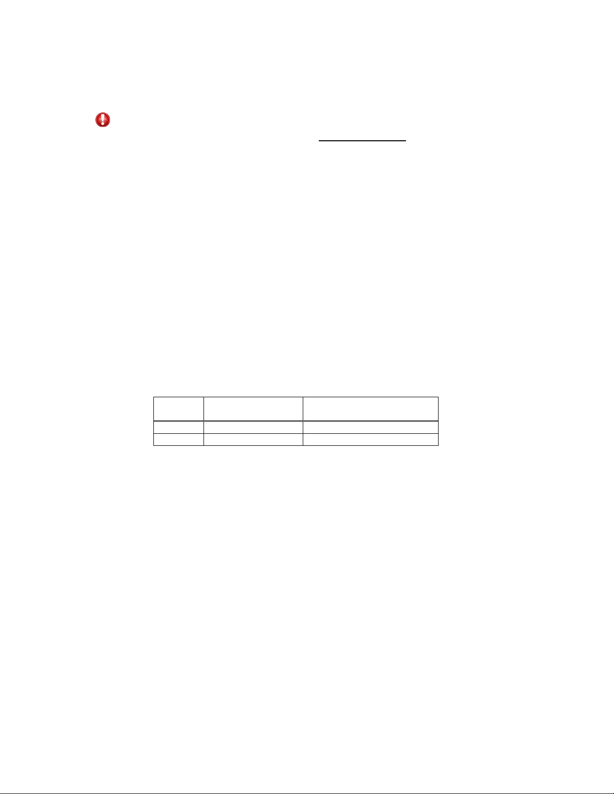
• Before selecting the method of control, verify that the inverter is in the STOP mode.
• There are two methods of control or combinations thereof that may be selected; Keypad and
RUN / STOP Command - Can be provided from the keypad or from an external contact
(see Fig. 2a).
Speed Reference – Can be from the keypad or from an external analog signal (0 – 10 VDC or
4 – 20 mA). see Fig’s 3a,3b, and 3c.
• The RUN/STOP method of control is set by parameter Sn – 04 and the Speed Reference is set
– Select Method of Control
Analog Signal.
by parameter Sn – 05. The following table shows the values to be set when selecting.
Value
*0 Keypad Keypad
1 External Contact External Analog
Start / Stop
Sn – 04=
Speed Reference
Sn – 05=
* NOTE
The factory default for Sn – 04 and Sn – 05 is set to 0; Digital Operator (Keypad) No
further parameter changes are necessary if this is the desired method of control. If
External Contact set to Sn – 04 or External Analog set to Sn – 05 is desired then proceed
as follows.
______________________________________________________________
TECO – Westinghouse Motor Company
4
Page 5

MA7200 PLUS Inverter 1 to 2 HP Fan Quick Start Manual
_______________________________________________________________
______________________________________________________________
TECO – Westinghouse Motor Company
5
Page 6

MA7200 PLUS Inverter 1 to 2 HP Fan Quick Start Manual
_______________________________________________________________
• After the method of control has been selected, if external control wiring is required, (e.g. external
analog), power down the inverter before removing any covers or making any connections.
In the following pages are wiring examples for Start / Stop, E-Stop, Restart, and Analog
Connections.
Danger
After the power has been turned OFF, wait at least 5 minutes until the charge
indicator extinguishes completely before touching any wiring, circuit boards, or
components.
______________________________________________________________
TECO – Westinghouse Motor Company
6
Page 7

MA7200 PLUS Inverter 1 to 2 HP Fan Quick Start Manual
_______________________________________________________________
DIGITAL INPUT / OUTPUT terminal connections (1 – 2 HP)
Fig’s 2a, 2b, and 2c below show the control terminal connections for input control functions. The
connections shown are typical and the user is referred to the MA7200 Manual if additional
information is required. Fig. 2d shows an example for the use of the Fault Output Relay.
STOP
RUN
______________________________________________________________
TECO – Westinghouse Motor Company
7
Page 8

MA7200 PLUS Inverter 1 to 2 HP Fan Quick Start Manual
_______________________________________________________________
ANALOG INPUT terminal connections (1 – 2 HP)
Fig’s 3a,3b, and 3c.show the various analog input schemes that can be used to control the
output frequency and thus the speed of the fan motor when External Analog is selected by
Sn-05 in Step 5. Only one method may be used as the input source with Fig. 3a Potentiometer
Input being most common.
______________________________________________________________
TECO – Westinghouse Motor Company
8
Page 9

MA7200 PLUS Inverter 1 to 2 HP Fan Quick Start Manual
_______________________________________________________________
MA7200 PLUS BLOCK DIAGRAM
Fig. 4 is an overall basic electrical connection diagram for MA7200 PLUS inverters rated 1 to 2
HP. It is used in conjunction with the other sections of this guide to give the user the ability to
successfully start up a Fan application. More detailed information is available in the MA7200
PLUS Manual to which the user is referred if further information is required.
______________________________________________________________
TECO – Westinghouse Motor Company
9
Page 10

MA7200 PLUS Inverter 1 to 2 HP Fan Quick Start Manual
_______________________________________________________________
Appendix A-
Changing display to read output speed in percent (%) of full speed.
The display is factory defaulted to show the inverter output frequency in Hz. If desired, the
display can be changed to show the output frequency as a percentage of full speed. To do this
parameter Cn-28 must be changed from (00000) to (00001) as follows:
To set parameter Cn-28 = 1
Keypad Steps
(Display Percent)
Resulting Display
1 - Press the
2 - Press the
3 - Press the
4 - Press the key
5 - Press the
6 - Press the
7 - Press the
PRGM
DRIVE
DSPL
key until display shows
EDIT
ENTER
key
EDIT
key to save
ENTER
PRGM
DRIVE
key
key 3 times
key to return to the main display.
An – 01 -
Freq. Cmd. 1
Cn – 01 Input Voltage
Cn-28-
Operator DSPL Unit
Cn-28 = 00000
Operator DSPL Unit
Cn-28 = 00001
Operator DSPL Unit
Entry Accepted
Cn-28 = 00001
Operator DSPL Unit
Flashing
Flashing
Flashing
2 Seconds
Flashing
______________________________________________________________
TECO – Westinghouse Motor Company
10
Page 11

MA7200 PLUS Inverter 1 to 2 HP Fan Quick Start Manual
_______________________________________________________________
Appendix B Removing the LCD Digital Operator and Inverter Cover(s)
______________________________________________________________
TECO – Westinghouse Motor Company
11
Page 12

 Loading...