

Page 1

HPE StoreEver MSL3040 Tape Library Getting Started Guide
Abstract
This guide provides information on installing the HPE StoreEver MSL3040 Tape Library. This
guide is intended for system administrators and other users who need physical knowledge of the
tape library.
Part Number: Q6Q62-00052
Published: November 2018
Edition: 3
Page 2

©
Copyright 2017, 2018 Hewlett Packard Enterprise Development LP
Acknowledgments
Microsoft® and Windows® are trademarks of the Microsoft group of companies.
Warranty
WARRANTY STATEMENT: To obtain a copy of the warranty for this product, see the Storage warranty
information website:
http://www.hpe.com/support/Storage-Warranties
Page 3

Contents
Overview.......................................................................................................5
Planning the installation........................................................................... 12
Installing the library...................................................................................16
Front panel.......................................................................................................................................... 5
Rear panel...........................................................................................................................................6
USB ports............................................................................................................................................ 7
Tape drive back panels........................................................................................................................7
MSL3040 power supply LEDs............................................................................................................. 8
Module and tape drive numbering.......................................................................................................8
MSL3040 storage slots........................................................................................................................9
Library user interfaces.......................................................................................................................10
Location requirements.......................................................................................................................12
Module and rack layout guidelines.................................................................................................... 13
FC connection information.................................................................................................................13
SAS connection information.............................................................................................................. 14
Library partition guidelines.................................................................................................................15
Preparing the host............................................................................................................................. 16
Unpacking the shipping containers....................................................................................................17
Installing the shelves in the rack........................................................................................................18
Installing the base module in the rack............................................................................................... 20
Preparing the top and bottom modules............................................................................................. 21
Installing the expansion modules in a rack........................................................................................24
Aligning and connecting modules......................................................................................................25
Installing optional power supplies......................................................................................................26
Installing tape drives..........................................................................................................................27
Connecting the Fibre Channel cables............................................................................................... 28
Connecting the SAS cable.................................................................................................................28
Powering on the library......................................................................................................................29
Initiating the configuration wizard...................................................................................................... 29
Verifying the host connections...........................................................................................................30
Configuring the FC interface..............................................................................................................30
Labeling tape cartridges.................................................................................................................... 30
Loading tape cartridges.....................................................................................................................31
Verifying the installation.....................................................................................................................32
Configuring additional features..........................................................................................................33
MSL3040 OCP menu..................................................................................34
Supported media....................................................................................... 36
Troubleshooting the installation.............................................................. 37
3
Page 4

Warning event code 4126: Cartridge found in inaccessible slot of lowermost
unit..................................................................................................................................................37
Warning event Drive disabled - no power supply available in module.................. 37
Related information................................................................................... 39
Product documentation......................................................................................................................39
Websites............................................................................................................................................39
4
Page 5
Overview
WARNING: Only personnel with technical and product safety training (referred to as users in this
document) may have access to or operate the HPE StoreEver MSL3040 Tape Library.
• Read all documentation and procedures before installing or operating the library.
• Install the library in a computer rack and verify that the front and rear doors are secure before
operating the tape library.
• Do not insert any tools or any part of your body into the tape library while it is operating.
The MSL3040 Tape Library provides a compact, high-capacity, low-cost solution for simple, unattended data
backup. This unique design houses 32 or 40 tape cartridges in each 3U module, with easy access to tape
cartridges through mailslots. The library is customer expandable with expansion modules and exchangeable
tape drives.
All library installations begin with a 3U base module, which has capacity for 32 or 40 tape cartridges and up to
three half-height LTO tape drives. The library is expandable with 3U expansion modules. Each expansion
module adds capacity for 40 tape cartridges and up to three LTO tape drives. Up to six expansion modules
can be added to the base module, for a maximum library capacity of 272 or 280 tape cartridges and 21 halfheight tape drives.
The library is compatible with most operating systems. However, the library requires either direct support from
the operating system or a compatible backup application to take advantage of its many features.
To verify the compatibility of backup applications, HBAs, and other components, see the StoreEver Support
Matrix at:
https://www.hpe.com/storage/StoreEverSupportMatrix
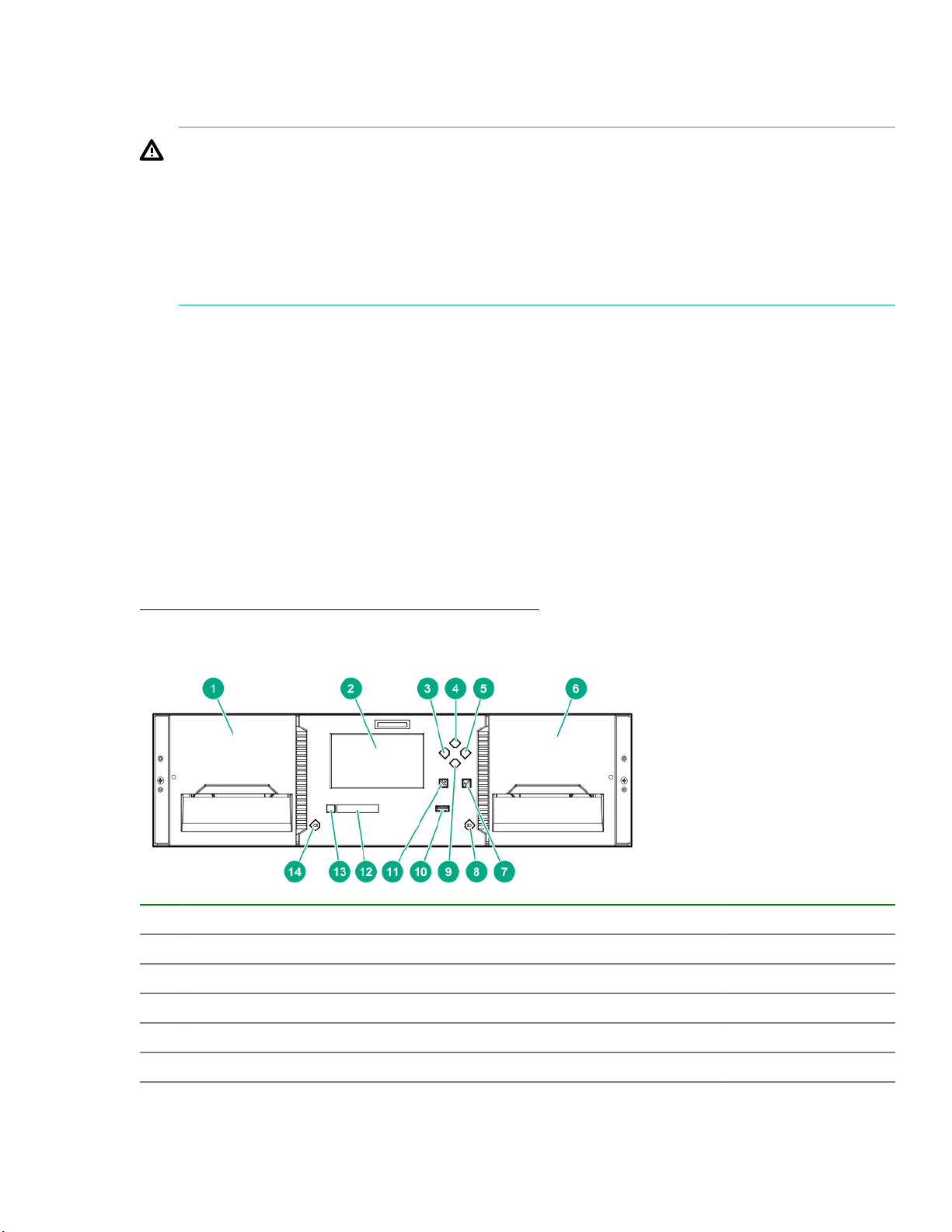
Front panel
1 Left magazine
2 Operator control panel (OCP) display Base module only
Navigation button - Left
3
Navigation button – Up
4
Navigation button – Right
5
Base module only
Base module only
Base module only
6 Right magazine and mailslot access
Table Continued
Overview 5
Page 6

7 Enter button Base module only
8 Right magazine release button
9 Navigation button – Down Base module only
10 USB port Base module only
Back/Return button
11
OCP LEDs, left to right
12
• Ready, green
• Unit identification (UID), blue
• Clean, amber
• Attention, amber
• Error, amber
13 Power button Base module only
14 Left magazine release button
Rear panel
Base module only
Base module only
1 Power supply bay 1
2 Power supply bay 2
3 Half-height tape drive bays
4 Lower expansion module connection port
5 Ethernet MGMT - used for the RMI connection Base module only
6 Ethernet DIAG - used for the CVTL Data Verification connection Base module only
7 USB port Base module only
8 Upper expansion module connection port
9 Module alignment mechanism
6 Overview
Table Continued
Page 7

10
1 2 3 4
1 2 3 4
Module controller LEDs, from top to bottom:
• Health status, green
• Error, amber
• Unit identifier (UID), blue
11
Product serial number tag location
USB ports
The library has two USB ports — one on the OCP and one on the back panel. You can update firmware, save
or restore configuration settings, or download support tickets with a USB thumb drive in either USB port.
The encryption kit token, which is part of the MSL Encryption Kit, is fully functional in both USB ports.
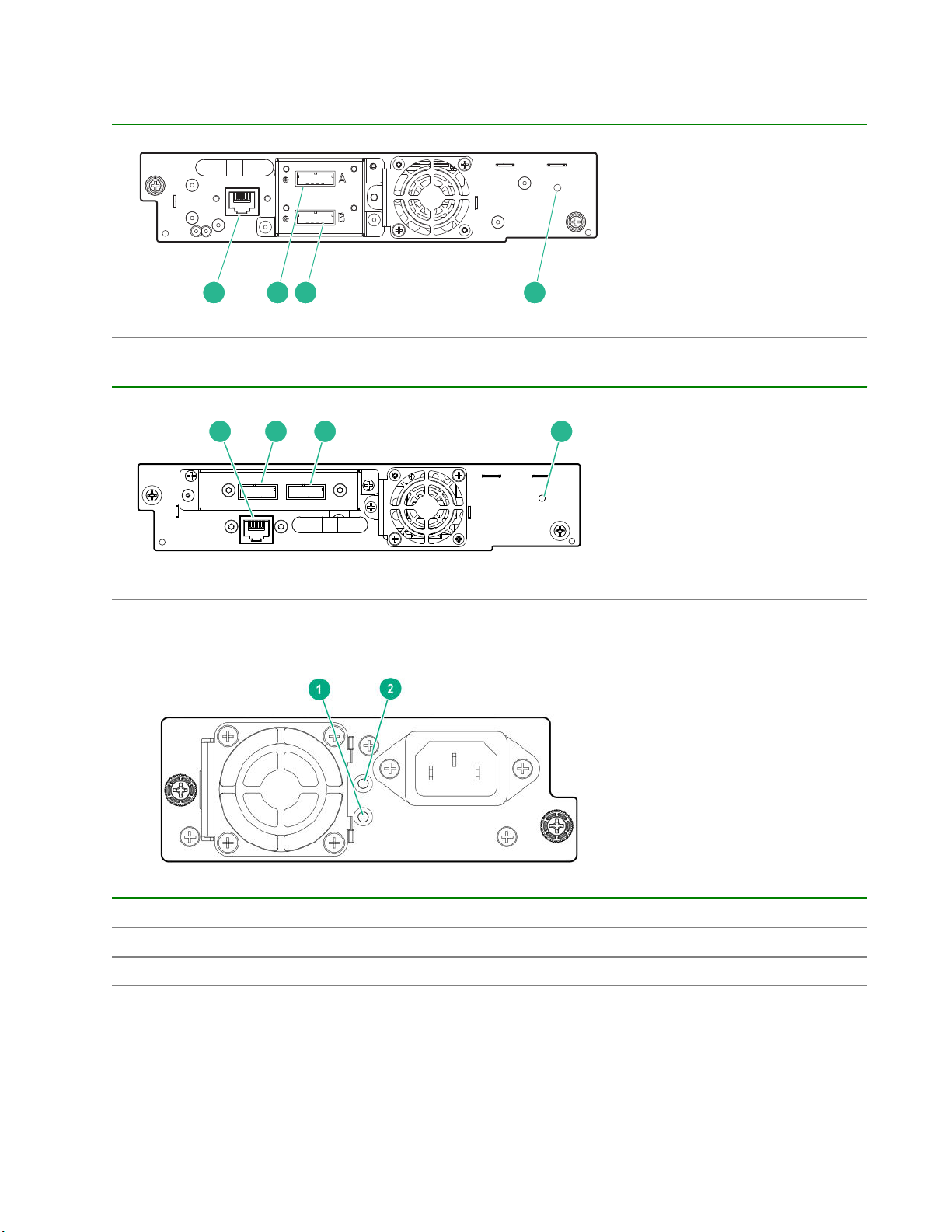
Tape drive back panels
Fibre Channel
Table 1: LTO-6 FC tape drive back panel
1. Tape drive Ethernet port
2. FC port A
3. FC port B
4. Tape drive power LED,
green
Table 2: LTO-7 and LTO-8 FC tape drive back panels
1. Tape drive Ethernet port
2. FC port A
3. FC port B
4. Tape drive power LED,
green
Overview 7
Page 8
SAS
1 2 3 4
1 2 3 4
Table 3: LTO-6 SAS tape drive
Table 4: LTO-7 and LTO-8 SAS tape drive back panels
1. Tape drive Ethernet port
2. SAS port A
3. SAS port B
4. Tape drive power LED,
green
1. Tape drive Ethernet port
2. SAS port A
3. SAS port B
4. Tape drive power LED,
green
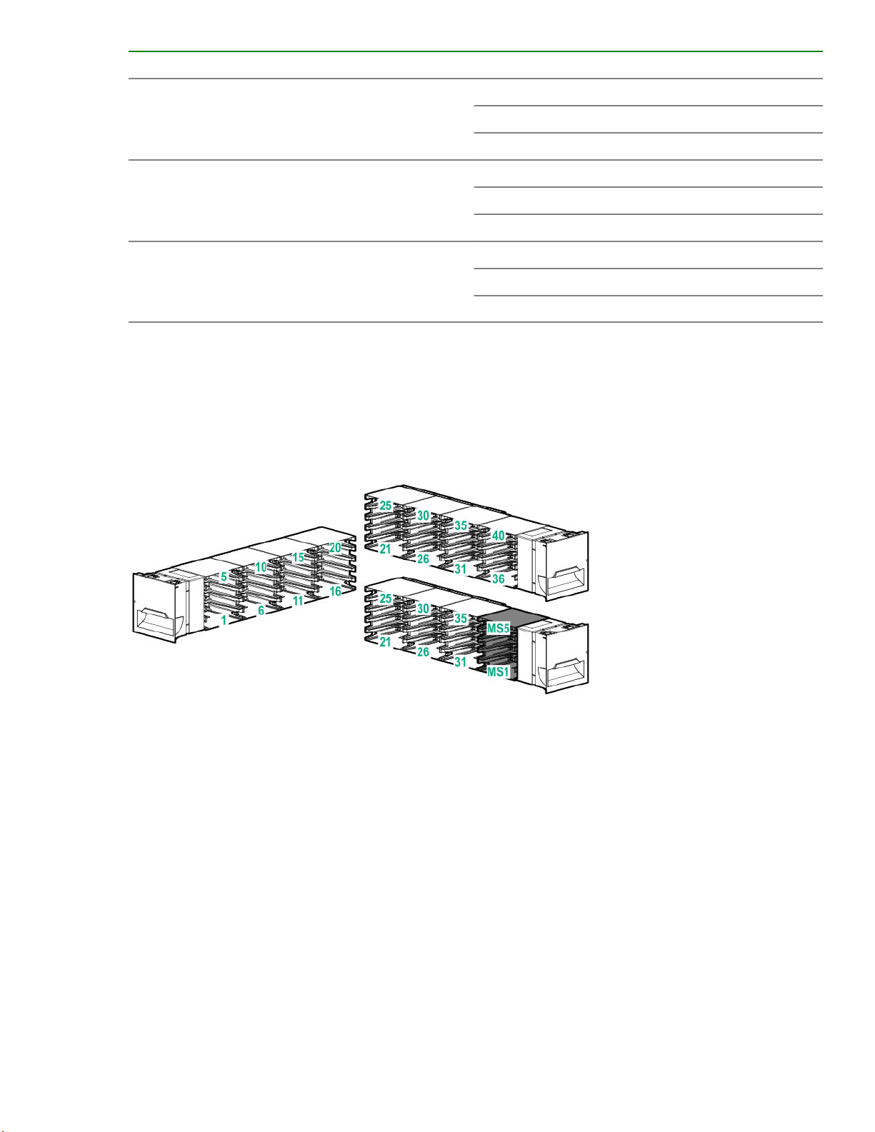
MSL3040 power supply LEDs
LED color Description
1 Green Module is powered on.
2 White AC power is connected.
Module and tape drive numbering
Modules and tape drives are numbered from the bottom of the library up, starting with the number one.
8 Overview
Page 9
Example module numbering Example tape drive numbering
Module 3 Drive 5
Module 2 (empty)
Module 1 (empty)
MSL3040 storage slots
Each MSL3040 module has two magazines of storage slots that can be removed from the front of the library.
Each magazine has 20 storage slots for tape cartridges.
The following illustration shows the slot numbers for all of the slots in the magazines.
The mailslot is in the right magazine. When enabled, the mailslot takes the place of storage slots 36-40.
(empty)
Drive 4
Drive 3
(empty)
Drive 2
Drive 1
Figure 1: Storage slot and mailslot numbering
Storage slot access for 40-slot robotic (Q6Q62B)
The robot is able to access all 40 storage slots within each module and there are no usage restrictions on the
eight lowest storage slots in the library.
Storage slot access for 32-slot robotic (Q6Q62A)
The robot cannot access the lowest row of storage slots in the library. If the library only has a base module,
the library will have 32 storage slots. Each expansion module adds 40 storage slots.
Overview 9
Page 10
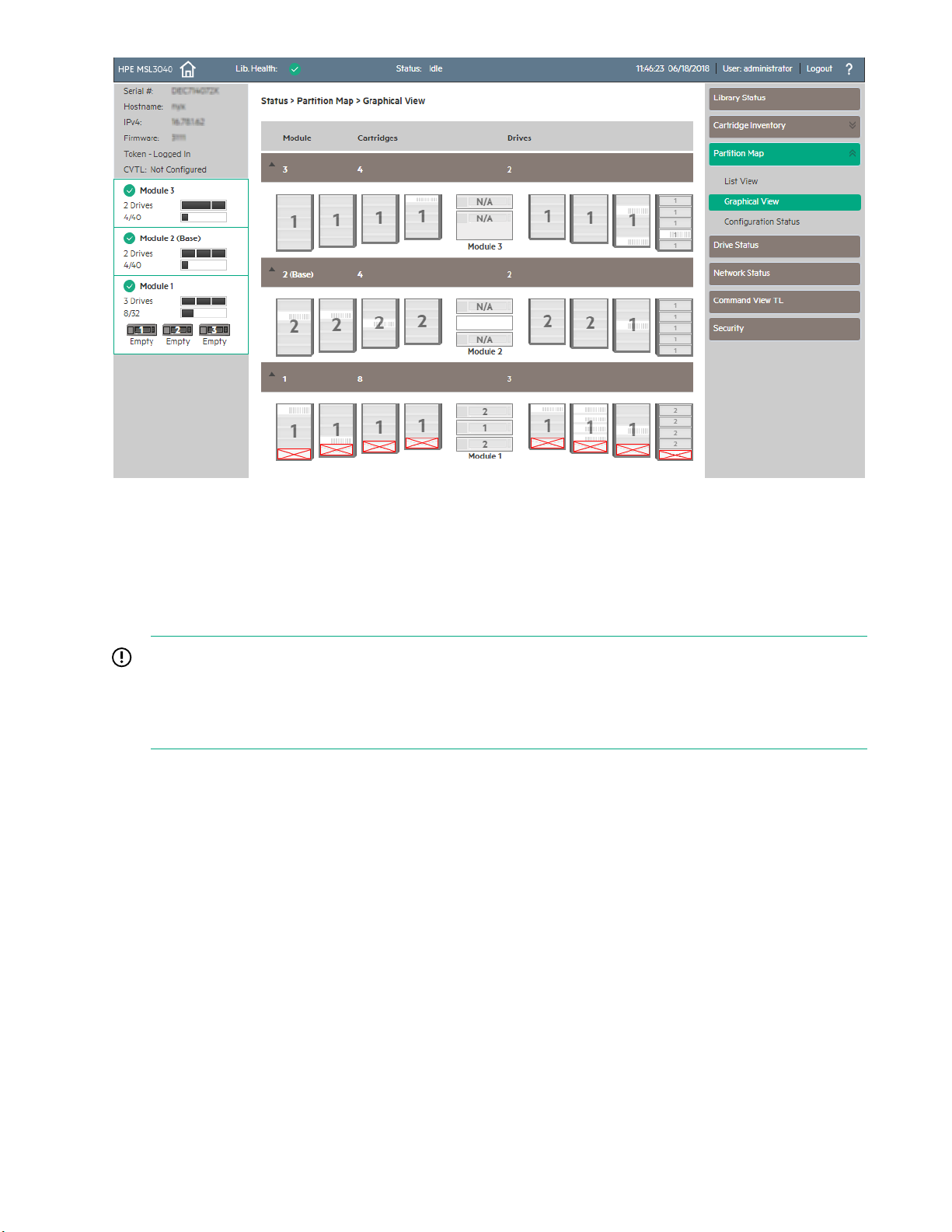
Figure 2: The lowest row of storage slots in the library are inaccessible to the robot if the library has a
Q6Q62A base module.
If an expansion module is installed below the Q6Q62A base module, the inaccessible storage slots will be in
the lowest expansion module and all of the storage slots in the base module will be accessible.
The numbers associated with the inaccessible storage slots are not used. For example, storage slots 1 and 6,
and mailslot MS1 are not visible in the RMI.
IMPORTANT: Do not install cartridges in any of the eight lowest storage slots in the library. If the library
detects cartridges in the eight lowest slots, the amber Attention LED will flash and the library will post a
Warning Event code 4126. The library will mark the cartridges as inaccessible and will not use them for
backup operations. Remove the cartridges from the eight lowest slots to clear the Warning Event and
turn off the flashing Attention LED.
Library user interfaces
• Remote management interface (RMI) — this interface lets you monitor and control the library from a web
page. You can access most library functions from the RMI.
• Operator control panel (OCP) — this interface lets you operate the library from the front panel.
The MSL3040 RMI
Before using the RMI, you must configure the library network settings and set the INITIAL RMI
administrator password with the OCP. You can configure the network settings and set the INITIAL RMI
administrator password with the Initial Configuration Wizard.
Use the INITIAL RMI administrator password to log in to the RMI the FIRST time as the administrator user.
The library will prompt you to set an actual RMI administrator password.
If one person physically installs the library and a second person configures the library using the RMI, share
the INITIAL RMI administrator password as appropriate. If the library is running firmware version 3210 or later,
10 Overview
Page 11
the RMI administrator password can be reset from the OCP. After resetting the RMI administrator password
from the OCP, share the new INITIAL RMI administrator password with the library administrator.
The security user password can be set once by the administrator from the Configuration > User Accounts
screen.
To start the RMI, open a supported HTML browser and enter the IP address of the library in the browser
address bar.
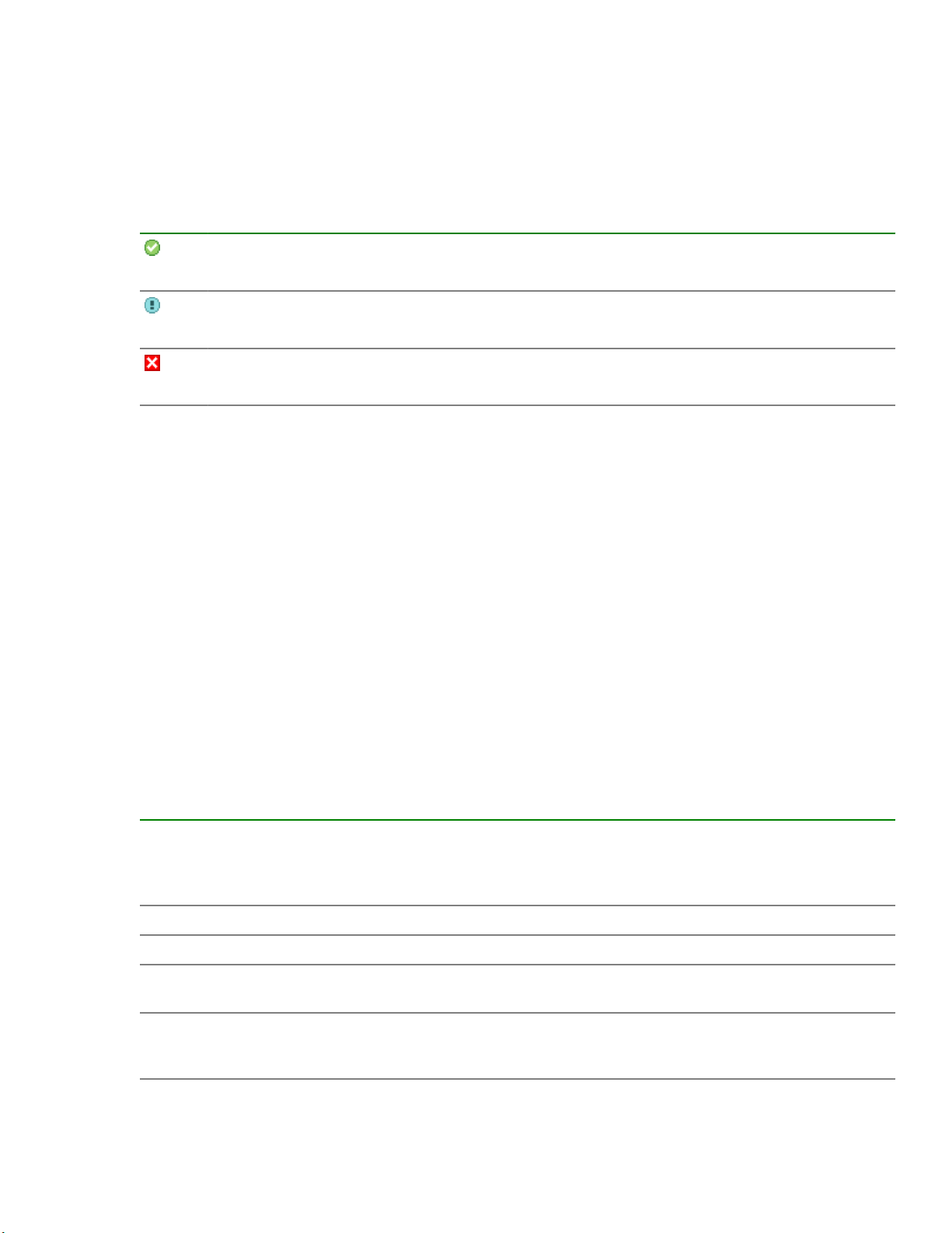
Status icons
The green Status OK icon indicates that the library is fully operational and that no user interaction
is required.
The blue exclamation point Status Warning icon indicates that user attention is necessary, but
that the device can still perform most operations.
The red X Status Error icon indicates that user intervention is required and that the device is not
capable of performing some operations.
The MSL3040 OCP
The OCP has a power button, four navigational buttons, an enter button, a back button, an LCD screen, and
five LEDs. With the OCP you can monitor, configure, and operate most library functions from the library front
panel. To navigate the OCP, use the navigational, enter, and back buttons.
To power on the library, press the power button. To power off the library, press the power button for 5 seconds
and then release it. When prompted, select the parking position for the robotic assembly.
Robotic assembly parking positions
• The default parked position — This option is applicable in most cases and best for all service options.
With this option, the robotic assembly returns to its home position behind the OCP.
If a parking position is not selected within 10 seconds, the library will park the robotic assembly in this
location.
• The shipping position—With this option the robotic assembly will move to the bottom of the base module
above the bottom cover. Select this option when the base module will be removed from the rack for
shipping or when the base module is the bottom module in a library that is shipping in a rack.
LED indicators
UID Blue when activated. The unit identification (UID) LEDs are controlled by the user through the
OCP Operations > UID LED Control screen and RMI Maintenance > UID LED Control
screen. The UIDs on the OCP and back panel are activated and deactivated together. The UIDs
are helpful for locating the library in a data center.
Ready Green, steady when power is on, blinking with tape drive or library robotic activity.
Clean Amber when a tape drive cleaning operation is recommended.
Attention Amber if the library has detected a condition for which user attention is necessary, but the library
can still perform most operations.
Error Amber if an unrecoverable tape drive or library error occurs. A corresponding error message is
displayed on the LCD screen. User intervention is required; the library is not capable of
performing some operations.
Overview 11
Page 12

Planning the installation
Procedure
1. Choose a location for the library.
Location requirements
2. Plan the rack layout.
Module and rack layout guidelines
3. Plan the SAS or Fibre Channel configuration and obtain the necessary cables.
• FC connection information
• SAS connection information
4. Library partition guidelines
Location requirements
The library must be installed in a supported rack on the provided rack shelves. Select a location with access
to the host server that meets the location requirements.
Table 5: Location requirements
Criteria Definition
Rack requirements HPE G2 Enterprise Series, Enterprise Series, G2 Advanced Series, Advanced
Series, Standard Series, and other HPE square hole or round hole racks
Rack space requirements 3U for the base module and 3U for each expansion module
Room temperature 10-35º C (50-95º F) for the tape library. Some tape drives have a more limited
temperature range when operating at high altitudes. Verify the tape drive
operating requirements before installing a tape drive in a high altitude
environment.
Power source
• AC power voltage: 100-240 VAC
• Line frequency: 50-60 Hz
• Library located near AC outlet(s)
The AC power cord is the library’s main AC disconnect device and must be
easily accessible at all times.
Table Continued
12 Planning the installation
Page 13

Criteria Definition
Air quality
Humidity 20-80 percent RH non-condensing
• Place the library in an area with minimal sources of particulate
contamination.
• Avoid areas near frequently used doors and walkways, stacks of supplies
that collect dust, printers, and smoke-filled rooms.
• Excessive dust and debris can damage tapes and tape drives.
Module and rack layout guidelines
When possible, install the base module near the middle of the rack at a convenient height for viewing and
operating the OCP and accessing the mailslot.
The library supports up to 3 expansion modules above and 3 expansion modules below the base module, for
a total of 7 modules. Each module occupies 3U.
For maximum library expansion, install the base module as the centered module of the rack, allowing 9U
above the top of the base module and 9U below the bottom of the base module.
If the library will be sharing the rack with other equipment, place heavy devices, such as disk arrays, in the
bottom of the rack to reduce the chance of the rack tipping.
FC connection information
Connect the FC tape drive directly to the server with an HBA or indirectly through a SAN with an FC switch.
Most supported tape drives have two FC ports. Only one port can be used at a time, but both ports can be
connected for path failover or with software that supports multipath. If you are using only one port, you can
use either port. Path failover is a licensed library feature.
Direct connection
The host must have a 2 Gb, 4 Gb, 8 Gb, or 16 Gb FC HBA. An 8 Gb or faster HBA is recommended for all
supported tape drives. To verify that an HBA is supported on your server and qualified for the library, see the
StoreEver Support Matrix at: https://www.hpe.com/storage/StoreEverSupportMatrix
A server that has FC-attached hard drives performs best with at least two FC ports. Using the same FC port
for disk and tape drive access can cause performance degradation.
SAN connection
All switches between the host and the tape drive must be of the appropriate type. A 2 Gb switch in the path
might cause performance degradation when backing up highly compressible data.
Configure zoning on the FC switch so that only the backup servers can access the tape drive. For more
information, see the switch documentation.
Cable requirements
An FC cable is required for each FC port you plan to use. The tape drive has an LC-style connector. The
maximum cable length is based on the tape drive and external cable type.
Planning the installation 13
Page 14

Cable type 2 Gb 4 Gb 8 Gb
OM2 0.5 – 300 m 0.5 – 150 m Not supported
OM3, OM4 0.5 – 500 m 0.5 – 380 m 0.5 – 150 m
SAS connection information
The server must have a SAS host bus adapter with an external connector.
The library uses two SCSI logical unit numbers (LUNs) and requires an HBA with multiple LUN support. Most
Hewlett Packard Enterprise SAS RAID controllers support tape devices; many other SAS RAID controllers do
not support tape devices. To verify the specifications of your HBA or find a list of compatible HBAs, see the
StoreEver Support Matrix: https://www.hpe.com/storage/StoreEverSupportMatrix
CAUTION: Do not connect the library to a SAS RAID controller unless the compatibility matrix shows
that the controller is qualified with the library. The server might not be able to boot when the library is
connected to an unsupported SAS RAID controller.
CAUTION: Reliable data transfer requires high-quality cables and connections.
• Always verify that the SAS cable is rated for the data transfer speed of the HBA and tape drive.
• Do not use adapters or converters between the HBA and the tape drive. SAS signal rates require
clean connections and a minimum number of connections between the HBA and the tape drive.
• SAS cables described as "equalized" might not support 6 Gb/s data rates. Do not use equalized
cables with LTO-6 or later generation tape drives unless these cables are verified for 6 Gb/s data
rates.
• For optimal performance, only use cables of the length specified as qualified for your products. Do
not use a SAS cable longer than 6 meters.
Cable requirements
Most SAS HBA ports have four SAS channels. A tape drive uses one channel, so each HBA port can support
up to four tape drives. You can use a cable with one connector on each end, but only one channel will be
used. The SAS fanout cable recommended for use with the library can connect up to four SAS tape drives to
a single SAS HBA port.
Figure 3: Example SAS fanout cable
Connectors
The host end of the cable must have the same type of connector as the HBA external SAS port.
14 Planning the installation
Page 15

The tape drive has a mini-SAS connector. The connector is keyed in location 4, which is the standard location
for end devices. If you use a cable other than the one recommended for use with the product, verify that it is
keyed in location 4.
CAUTION: Mini SAS connectors are keyed. Do not force a SAS cable mini-SAS connector into the tape
drive mini-SAS port because it might be keyed differently.
Library partition guidelines
Partition constraints
The library has a flexible partitioning scheme with the following constraints:
• Each partition must have at least one tape drive. One tape drive in each partition hosts the library LUN for
the partition.
• The maximum number of partitions is 21.
• Magazine slots are allocated to partitions in five-slot groups, except for a 32-slot library (Q6Q62A), in
which case the slots may be in four or five slot groups depending on whether the magazine slots are
located in the bottom module or not.
• Mailslots must be enabled for a module before they can be allocated to a partition.
A partition does not need to have a mailslot. If a partition does not have a mailslot, the magazine must be
accessed to import or export cartridges. Opening a magazine takes the library off line.
Although the mailslot magazine is shared between partitions, the mailslot elements are assigned
individually to partitions.
Partition wizards
Wizards guide you through the partition configuration process. The wizards are only accessible from the RMI.
• Basic Partition Wizard – You specify the number of partitions. The wizard removes the current partition
configuration and assigns the drives and storage slots as evenly as possible to the partitions. Any extra
drives or slots are assigned to the first partition.
Use the Basic Partition Wizard to configure partitions that will have similar resources. For a library with a
single partition, use the Basic Partition wizard to configure the number of barcode characters to report to
the host application and whether to report them from the left or right end of the label.
• Expert Partition Wizard – You add or remove partitions from the current partition configuration and then
edit each partition configuration to add or remove library resources.
Use the Expert Partition Wizard to configure partitions that will have different resources or to adjust
resource assignments for existing partitions or partitions created with the Basic Partition Wizard.
CAUTION: The library goes off line while partitions are being configured. Ensure that all host operations
are idle before running a partition wizard.
Planning the installation 15
Page 16
Installing the library
WARNING: Each library module weighs 20 kg (44 lb) without media or tape drives and at least 35 kg
(77 lb) with media (40 cartridges) and three tape drives. When moving the library, to reduce the risk of
personal injury or damage to the device:
• Observe local health and safety requirements and guidelines for manual material handling.
• Remove all tapes to reduce the overall weight of the device and to prevent cartridges from falling into
the robotic path and damaging the library. Keep the cartridges organized so they can be returned to
the same locations.
• Obtain adequate assistance to lift and stabilize the device during installation or removal.
WARNING: When placing the library into a rack, to reduce the risk of personal injury or damage to
equipment:
• Extend the rack leveling jacks to the floor.
• Ensure that the full weight of the rack rests on the leveling jacks.
• Install the rack stabilizer kit on the rack.
• Extend only one rack component at a time. Racks may become unstable if more than one
component is extended.
CAUTION: Slide/rail mounted equipment is not to be used as a shelf or a work space.
IMPORTANT: Verify that the rack is level front to back and side to side before installing a module into
the rack. Racks that are not level can prevent the modules from aligning properly.
Tools required:
Small flat head and #1 Phillips screwdrivers
Preparing the host
CAUTION: Parts can be damaged by electrostatic discharge. Keep parts in electrostatic containers until
needed. Ensure that you are properly grounded when touching static sensitive components.
Procedure
• Check with a system administrator before powering off the host computer.
• For a library with SAS drives, confirm availability or install a SAS HBA that supports multiple LUNs.
• For a library with direct-attach Fibre Channel drives, confirm availability or install an FC HBA.
• For a library with Fibre Channel drives connected through a compatible switch, verify that sufficient ports
are available.
16 Installing the library
Page 17
Unpacking the shipping containers
Prerequisites
Before unpacking any modules, clear a level work surface near where you will install the modules.
CAUTION: If the temperature in the room where the module will be installed varies by 15º C (30º F)
from the room where it was stored, allow the module to acclimate to the surrounding environment for at
least 12 hours before unpacking it from the shipping container.
NOTE: If you are installing a library with multiple modules and have limited work space, locate and unpack
the base module first, along with the rack shelves and accessory kits for all of the expansion modules.
Procedure
1. Before opening and removing a module from the box, inspect the container for shipping damage.
If you notice any damage, report it to the shipping company immediately.
2. Unpack the module and accessories from the box, one layer at a time. Place the module on a work table.
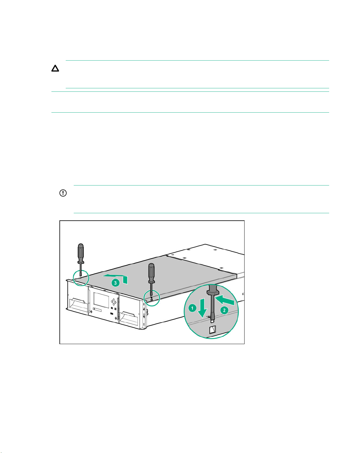
3. Remove the protective foam insert from the base module. This step does not apply to expansion modules.
The robotics is protected during shipment by a foam insert that must be removed before installation.
IMPORTANT: To avoid personal injury or damage to the module, always support the bottom of the
module where the rack shelf contacts the module. Do not touch internal mechanical or electrical
components while moving the module.
a. Use two small screwdrivers to unlock the top cover.
b. Lift the cover front end by about 12 cm and pull gently forward to disengage from the pivot point at the
module center.
c. Remove the foam insert.
4. If you are installing a base module only without an expansion module or the base module will be the top
module in the library, replace the top cover on the base module.
Installing the library 17
Page 18
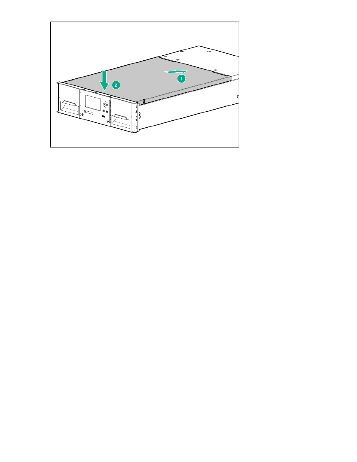
5. If you are installing a library with an expansion module above the base module, keep the top cover with the
base module until the cover is installed on the top expansion module.
6. Save the packaging materials for future use.
Installing the shelves in the rack
Each module is supported by a pair of shelves and is secured to the rack with captive fasteners.
For easier installation when installing a library with multiple modules, install all the shelves before installing
any of the modules.
Prerequisites
• Rackmount accessory kit for each module containing:
◦ Four adapter blocks
◦ Four Phillips screws
◦ Two rack shelves, one for each side of the rack, labeled LHS and RHS
• #3 Phillips screwdriver
Procedure
1. When installing multiple modules, locate the shelf locations for all modules.
a. Locate the bottom of the lowest full U where the lowest module will be installed.
b. Count up the rack 3U for each module until all the module locations are identified.
2. From the front of the rack, mount an adapter block at the appropriate height for each module on the front
rack posts.
a. Orient the adapter block for your rack.
18 Installing the library
Page 19
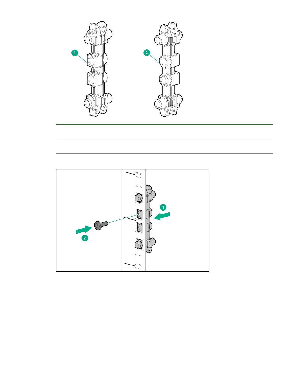
1. Orientation for a square-hole rack. The face with square inserts is installed into the square rack
holes.
2. Orientation for a round-hole rack. The face with the round inserts is placed against the rack
posts.
b. Align the adapter block in the bottom 2U of the 3U volume that the module will occupy, as shown in the
illustration.
c. Secure the adapter block with a Phillips screw from the accessory kit.
3. From the rear of the rack, mount an adapter block at the same height as each corresponding front adapter
block.
4. From the front of the rack, starting at the rear adapter, mount the LHS rack shelf for each module into the
adapter blocks on the left side of the rack.
Installing the library 19
Page 20

5. From the front of the rack, starting at the rear adapter, mount the RHS rack shelf for each module into the
adapter blocks on the right side of the rack.
6. Ensure that each rack shelf tab is properly engaged with the front and rear adapters. Verify that the rack
shelf cannot move in the front-to-back axis of the rack.
Installing the base module in the rack
Prerequisites
#2 Phillips screwdriver
Procedure
1. If the top cover is not installed on the base module, set it aside on the work table.
2. From the front of the rack and while supporting the bottom of the module in the areas supported by the
rack shelves, set the back of the base module on the front of the shelves.
3. Push the base module into the rack until the front of the module contacts the front rack posts.
20 Installing the library
Page 21
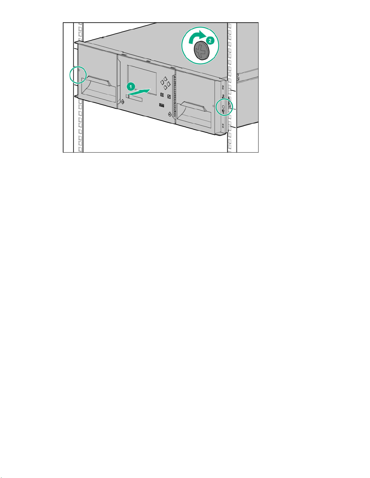
4. Use a #2 Phillips screwdriver to tighten the captive fasteners on each side of the base module until they
are finger tight. Do not over tighten.
5. Verify that the module is contained within the 3U rack volume.
Preparing the top and bottom modules
Skip this step if you are installing a base module only, without any expansion modules.
The base module has removable top and bottom cover plates.
Procedure
1. If an expansion module will be installed above the base module, move the top cover plate from the base
module to the top of the expansion module that will be installed at the top of the library.
2. If an expansion module will be installed below the base module, move the bottom cover plate from the
base module to the bottom of the expansion module that will be installed at the bottom of the library.
Moving the top cover plate
Procedure
1. Remove the top cover plate from the current module.
Installing the library 21
Page 22
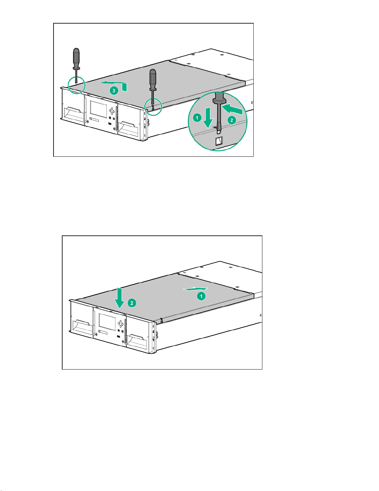
a. Unlock the top cover using two small screwdrivers.
b. Lift the cover front end by about 12 cm.
c. Gently pull the cover forward to disengage from the pivot point at the module center.
2. Install the cover plate on the other module.
a. With the front of the top cover raised approximately 12 cm, engage the rear of the cover at the module
pivot point located at the back of the opening.
b. Lower the front of the cover until the latches engage on both sides.
22 Installing the library
Page 23

Moving the bottom cover plate
Prerequisites
• The base module is installed in a rack with at least 3U open below.
• The base module has either not been powered on or the robot is locked.
Procedure
1. Remove the bottom cover plate from a module.
a. Support the bottom cover with one hand. Insert a small flathead screwdriver or Torx screwdriver into the
slot and slide about 4 mm sideways to unlock the spring loaded lock.
b. Lower the cover front end by about 10 cm and pull gently forward to disengage from the cover pivot
point at module center.
c. Remove the cover from the module.
2. Install the bottom cover plate on the other module.
Installing the library 23
Page 24

a. Place the module upside-down on a work table.
b. Insert the back of the cover at the module center.
c. Lower the cover front edge until you feel a hard stop and the cover locks in at the front of the module.
Installing the expansion modules in a rack
Skip this step if the library does not have expansion modules.
TIP: When installing multiple expansion modules, work from the base module to the top of the library
and then from the base module to the bottom of the library.
Prerequisites
• The rack shelves are installed.
• The library cover plates are on the modules that will be on the top and bottom of the library.
Procedure
1. From the front of the rack while supporting the bottom of the module in the areas supported by the rack
shelves, set the back of the expansion module on the front of the rack shelves. Push the module into the
rack until the front of the module contacts the rack posts.
2. Verify that this module has been installed directly above or below its adjacent module and is contained with
the correct 3U volume.
The gap between modules must be less than 4mm.
3. Use a #2 Phillips screwdriver to tighten the captive fasteners on each side of the expansion module until
they are finger tight. Do not over tighten.
4. Repeat for any other expansion modules.
5. Verify that the top cover plate is at the top of the library and that the bottom cover plate is at the bottom of
the library.
24 Installing the library
Page 25
Aligning and connecting modules
Skip this step if the library does not have expansion modules.
Procedure
1. From the front of the library, loosen the screws on each of the modules two full turns.
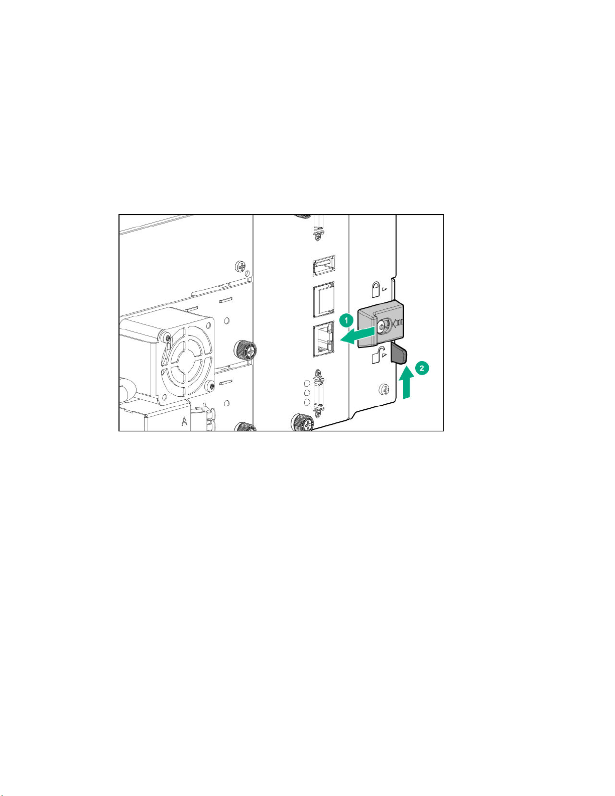
2. From the back of the library, starting with the bottom pair of modules, align each module with the module
below. Repeat for each pair of adjacent modules.
a. Lock the alignment mechanism.
If the alignment mechanism has a lock, slide the lock to the left, move the alignment mechanism to the
locked position, and then release the spring-loaded lock.
If you encounter resistance, adjust the position of the upper module so the pin in the alignment
mechanism moves into the mating hole in the lower module.
3. Verify that the lowest module in the library has its alignment mechanism in the unlocked position.
4. From the front of the library, use a #2 Phillips screwdriver to tighten the captive fasteners on each side of
all of the modules until the fasteners are finger tight. Do not over tighten.
5. From the back of the library, connect each adjacent pair of modules with expansion interconnect cables, if
not already connected.
Installing the library 25
Page 26

Installing optional power supplies
Each module supports up to two power supplies. The base module is shipped with one power supply
installed. Expansion modules are shipped without a power supply.
If an expansion module will have one or more tape drives, it must have a power supply.
When present and connected to a different AC power source, the second power supply in the module
provides redundancy.
Procedure
1. Using a #2 Phillips screwdriver, remove the power supply bay cover.
When installing the first power supply in an expansion module, the power supply can be installed in either
bay.
2. Position the new power supply on the alignment rails.
3. Slide the power supply into the module until it is flush with the back panel of the module.
26 Installing the library
Page 27
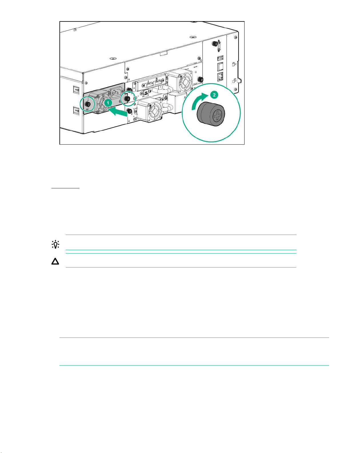
4. Tighten the blue captive thumbscrews with your fingers or a #2 Phillips screwdriver until it is finger tight.
Do not over tighten.
More information
Rear panel on page 6
Installing tape drives
When possible, install all tape drives during the initial library installation process before the library is powered
on. When installing additional tape drives after the library has been powered on, follow the instructions
included with the tape drive.
TIP: To assist in aligning the drive, only remove the drive bay covers for one drive at a time.
CAUTION: All drive bays without tape drives installed must have drive bay covers installed.
Prerequisites
• The module must have a power supply installed before powering on the library.
• #2 Phillips screwdriver
Procedure
1. Locate an appropriate vacant drive bay on the back of the library.
NOTE: A full-height drive can only be installed in the bottom two half-height drive bays. A full-height drive
cannot be seated in other locations and will not operate. If the drive will not seat completely, verify that it is
located in the correct drive bays.
2. Remove the face plate covering the drive bay by removing the screws holding it in place.
3. Holding the tape drive by the handle and supporting it from the bottom, slide the tape drive along the
alignment rails into the drive bay until it is flush with the back of the library.
Installing the library 27
Page 28
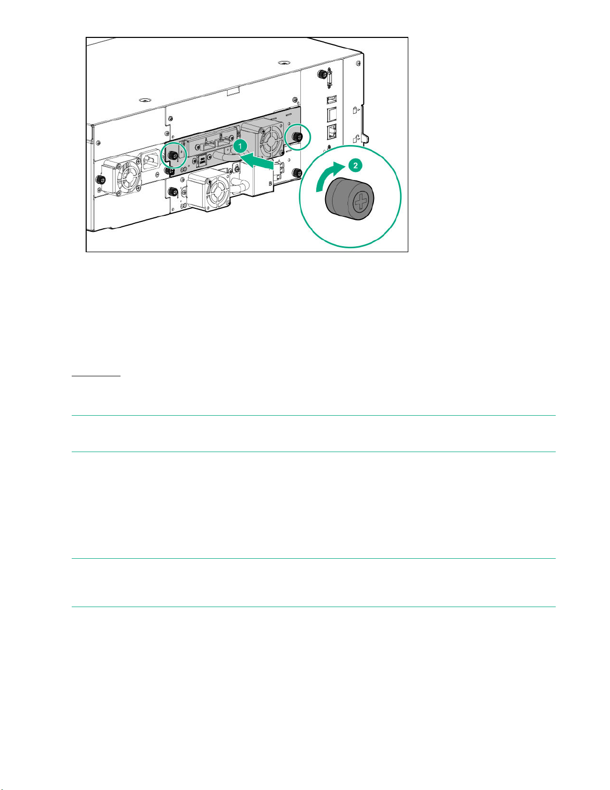
4. To secure the tape drive to the chassis, use a torque driver to tighten the blue captive thumbscrews on the
drive sled to 6 inch pounds or 0.68 N m.
If a torque driver is not available, use a #2 Phillips screwdriver to tighten the thumbscrews until a low initial
threshold torque achieves a snug tight condition.
If the thumbscrews cannot be tightened, verify that the tape drive is aligned properly.
More information
Rear panel on page 6
Connecting the Fibre Channel cables
NOTE: Using both ports on a dual-port drive requires multipath capability in the host application. For
information about configuring the second port, see the application documentation.
Procedure
1. Remove the FC port caps if necessary. Attach one end of the FC cable to port A on the tape drive.
2. Attach the other end of the FC cable to a switch or HBA.
Connecting the SAS cable
NOTE: SAS signal rates require clean connections between the HBA and tape drive. Do not use adapters or
converters between the HBA and the tape drive. For reliable operation, use a maximum SAS cable length of
six meters.
Procedure
1. Attach the HBA end of the SAS cable into the connector on the HBA. If you are using a SAS fanout cable,
the end of the cable with only one connector should be plugged into the HBA.
2. Connect the drive end of the cable.
28 Installing the library
Page 29

• When using a cable with a single connector on each end, attach the other end into the connector on the
tape drive.
• When using a SAS fanout cable, attach one mini-SAS connector into the connector on each tape drive.
The unused ends of the SAS fanout cable are single channel and not suitable for use with disk arrays.
Use the other ends to connect tape drives, or coil and secure them to the rack to minimize stress on the
connectors.
TIP: When using a SAS cable not specified for the library, do not force a SAS cable's mini-SAS
connector into the tape drive mini-SAS connector because it might be keyed differently.
NOTE: Each of the tape drives uses one channel and the fanout cable recommended for use with the
library maps each of the four channels from the HBA to one channel on the drive end.
You can plug any of the four drive connectors into any tape drive.
Powering on the library
Procedure
1. Plug the power cables into the power connectors on each module and into power outlets.
TIP: If a module has two power supplies, plug each power cord into a different AC power circuit to
increase redundancy.
2. To use the RMI, connect an Ethernet cable from MGMT Ethernet port on the base module controller to
your network.
3. Power on the library by pressing the power button on the base module just under the OCP. The green light
and OCP will illuminate.
When the library is powered on, it performs the following procedures:
• Inventory the tape cartridges in the magazines
• Check the firmware version on all modules
• Configure the tape drives
• Confirm the presence of the existing modules
• Search for any new modules
Initiating the configuration wizard
Procedure
1. Log in to the OCP as the administrator user.
The initial configuration wizard starts upon first login.
2. Follow the instructions in the wizard to configure the network, date, and time settings, and set the INITIAL
RMI administrator password.
The INITIAL RMI administrator password is a four-digit PIN that is set from the OCP.
Installing the library 29
Page 30

3. Log in to the RMI as the administrator user.
Use the INITIAL RMI administrator password that was set from the OCP to log in to the RMI the first time.
The library will prompt you to set an actual RMI administrator password. If one person physically installs
the library and a second person will configure the library using the RMI, share the INITIAL RMI
administrator password as appropriate.
4. Navigate to Configuration > Configuration Wizard from the RMI to complete the library configuration.
Verifying the host connections
Procedure
1. Install the application software and/or drivers that are compatible with the library.
Backup software packages might require additional software or licensing to communicate with the robotics.
For compatibility information, see the StoreEver Support Matrix at:
https://www.hpe.com/storage/StoreEverSupportMatrix
2. Verify the connection between the library and the host using the host server operating system utilities or
Library and Tape Tools (L&TT).
L&TT verifies that the unit is connected and communicating with the host server. It also verifies that the
device is functioning and provides diagnostic information. L&TT is available without charge at:
http://www.hpe.com/support/TapeTools
Configuring the FC interface
Procedure
1. Navigate to the RMI Configuration > Drives screen.
2. Configure the settings for your drive and connection method.
Drives connected to a SAN
Leave the FC port at the default settings of Port Speed: Automatic and Port Type: Automatic. With
these settings, the tape drive will use the appropriate configuration.
Drives connected directly to the host
• For LTO-7 and LTO-8 drives, set Port Type to Loop mode.
• For LTO-6 drives, leave the FC port at the default settings of Port Speed: Automatic and Port Type:
Auto Detect. With these settings, the tape drive will use the appropriate configuration.
3. Click Submit.
Labeling tape cartridges
Using unlabeled media can significantly increase the inventory scan time and is therefore not recommended
for normal operation.
IMPORTANT: Misusing and misunderstanding bar code technology can result in backup and restore
failures. To ensure that your bar code labels meet Hewlett Packard Enterprise quality standards, always
purchase them from an approved supplier and never print bar code labels yourself.
30 Installing the library
Page 31
Procedure
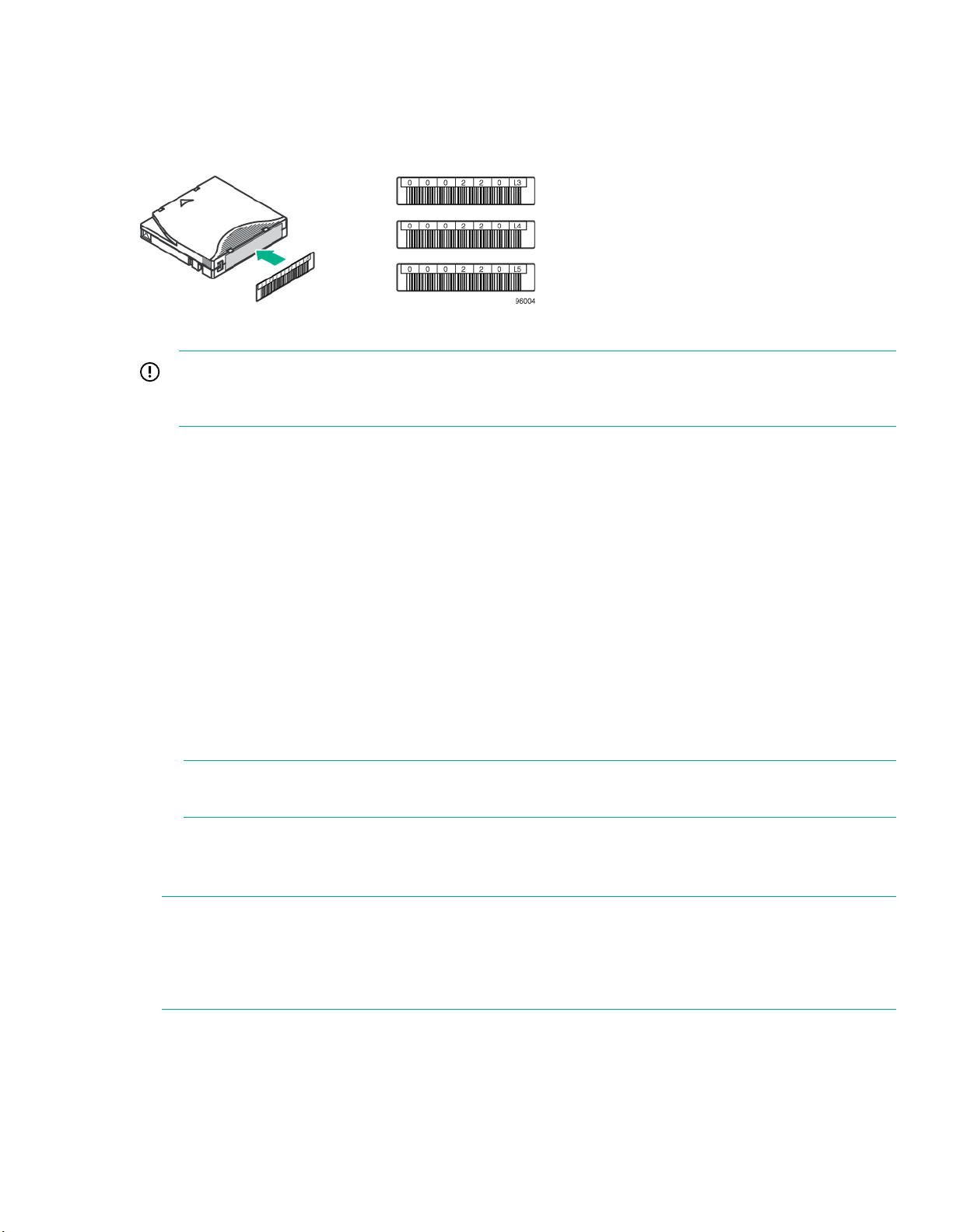
Apply a high-quality preprinted bar code label to each tape cartridge.
LTO tape cartridges have a recessed area on the face of the cartridge next to the write-protect switch. Use
this area for attaching the adhesive-backed bar code label.
Figure 4: Apply the label within the recessed area
IMPORTANT: Only apply the bar code label as shown, with the alphanumeric portion facing the hub
side of the tape cartridge. Never apply multiple labels onto a cartridge because extra labels can cause
the cartridge to jam in a tape drive.
Loading tape cartridges
The library will power on without tape cartridges. However, the library needs cartridges before performing data
read or write operations, or any tests or operations that transfer cartridges.
Procedure
1. Open a magazine.
a. From the OCP, navigate to the Open Magazine/Mailslot > Open Magazine screen.
The library lights the magazine release button for each magazine in the library.
b. Press the magazine release button for the magazine to be opened.
The library will release the lock.
c. Pull the magazine straight out of the library, supporting the bottom with your hand.
NOTE: If the magazine has not been extended or removed from the library within 30 seconds, the
library will relock the magazine.
2. Load the cartridges.
Insert one or more labeled cartridges into the storage slots in the magazine.
NOTE: 32-slot (Q6Q62A) only—Do not install cartridges in any of the eight lowest storage slots in the
library. If the library detects cartridges in the eight lowest slots, the amber Attention LED will flash and the
library will post a Warning Event code 4126. The library will mark the cartridges as inaccessible and will
not use them for backup operations. Remove the cartridges from the eight lowest slots to clear the
Warning Event and turn off the flashing Attention LED.
3. Insert the magazine into the magazine slot.
The library waits 10 seconds after a magazine has been reinserted before starting the inventory process.
During this time, press a magazine release button to release another magazine. If another magazine
Installing the library 31
Page 32

release button is not pressed during those 10 seconds, the library locks all magazines and starts the
inventory process.
More information
MSL3040 storage slots on page 9
Verifying the installation
IMPORTANT:
• The library will only operate with both top and bottom library cover plates installed.
• Do not place anything on the top library cover plate, the weight may cause errors in the library
operation.
• Do not allow anything to contact the bottom library cover plate, contact may cause errors in the
library operation.
Procedure
1. Verify that the library and drives have the current firmware revision.
The library firmware revision is displayed in the top left corner of the OCP and RMI screen.
The drive firmware version is displayed on the RMI Status > Drive Status screen and the OCP Status >
Drive screen.
2. If necessary, update the library firmware from the OCP or RMI Maintenance > Firmware Upgrades >
System Firmware screen.
3. After configuring the library, you can save the configuration settings to a USB flash drive from the OCP
Configuration > Save/Restore > Save Configuration File or to a file on your computer from the RMI
Configuration > System > Save/Restore screen.
Having a backup of the library configuration is helpful when recovering from a configuration error or if the
library needs service.
4. Set the security user password from the Configuration > User Accounts screen.
Downloading product firmware
Procedure
1. Navigate to the HPE Support website: http://www.hpe.com/support/storage
IMPORTANT: Access to some updates might require product entitlement when accessed through
the Hewlett Packard Enterprise Support Center. You must have an HPE Passport set up with
relevant entitlements.
To view and update your entitlements, and to link your contracts and warranties with your profile,
navigate to: http://www.hpe.com/support/AccessToSupportMaterials
2. Browse or search for the necessary firmware.
3. Download the firmware.
To upgrade firmware from the OCP, copy the firmware image onto a FAT-32 formatted USB flash drive.
32 Installing the library
Page 33

Configuring additional features
The library has many features to customize it for your organization.
For configuration procedures and troubleshooting information, see the user guide.
Procedure
• Enabling the mailslot.
• Configuring partitioning and additional library parameters using one of the partitioning wizards.
◦ Basic Partition Wizard — Use the Basic Partition Wizard to configure partitions that will have similar
resources or to configure the number of bar code characters to report to the host application and
whether to report them from the left or right end of the label for a library with a single partition.
◦ Expert Partition Wizard — Use the Expert Partition Wizard to configure partitions that will have different
resources or to adjust resource assignments for existing partitions or those partitions created with the
Basic Partition Wizard.
• Modifying the default tape drive settings.
NOTE: When connecting an LTO-7 or later FC tape drive directly to the host, configure the FC port in Loop
mode.
• Enabling and configuring SNMP network management.
• Enabling and configuring Command View TL integration and Data Verification.
• Setting up email event notification.
• Using the MSL Encryption Kit.
Installing the library 33
Page 34

MSL3040 OCP menu
• Initial Setup
• Operation
◦ Move Media
◦ Move Cartridge from Drive to Home Slot
◦ Inventory Scan
◦ UID LED Control
• Configuration
◦ Date & Time
◦ Network Settings
◦ Drive Power On/Off
◦ User Accounts
– Change PIN
– Restricted RMI Login
◦ Save/Restore
– Save Configuration File
– Restore Configuration File
– Reset Default Settings
– Reset List of Known Drives and Modules
– Reset Default Manufacturing Settings
• Maintenance
◦ Library Tests
– System Test
– Slot to Slot Test
– Robotic Test
– OCP Test
– Wellness Test
◦ View Event Ticket Logs
◦ Drive Support Ticket Download
◦ Library Support Ticket Download
◦ Library Logs Download
◦ Drive Firmware Upgrade
34 MSL3040 OCP menu
Page 35

◦ Library Firmware Upgrade
◦ Move Robotic to Base Module
◦ System Reboot
◦ LCD Adjustment
◦ SSH (Secure Shell)
• Open Magazines/Mailslots
• Status
◦ Network Settings
◦ Library
◦ Drive
• About
• Logout
MSL3040 OCP menu 35
Page 36

Supported media
Use Hewlett Packard Enterprise storage media to prolong the life of the library and tape drives. To learn more
about, or to purchase media, see:
Table 6: Cleaning cartridge for all supported tape drives
Cartridge type Part number
HPE Ultrium universal cleaning cartridge (50 cleans), orange C7978A
Table 7: LTO-6 data cartridges
Cartridge type Part number
HPE LTO-6 Ultrium 6.25 TB MP RW Data Tape, purple C7976A
HPE LTO-6 Ultrium 6.25 TB BaFe RW Data Tape, purple C7976B
HPE LTO-6 Ultrium 6.25 TB MP WORM Data Tape, two-tone (purple and gray) C7976W
HPE LTO-6 Ultrium 6.25 TB BaFe WORM Data Tape, two-tone (purple and gray) C7976BW
Table 8: LTO-7 data cartridges
Cartridge type Part number
http://www.hpe.com/storage/storagemedia
HPE LTO-7 Ultrium 15 TB RW Data Tape, blue C7977A
HPE LTO-7 Ultrium 15 TB WORM Data Tape, two-tone (blue and gray) C7977W
Table 9: LTO-7 Type M media for LTO-8 drives
Cartridge type Part number
HPE LTO-7 Ultrium Type M 22.5 TB RW Custom Labeled Data Cartridges (20
pack)
HPE LTO-7 Ultrium Type M 22.5 TB RW Non-Custom Labeled Data Cartridges (20
pack)
Q2078ML
Q2078MN
Table 10: LTO-8 data cartridges
Cartridge type Part number
HPE LTO-8 Ultrium 30 TB RW Data Tape, green Q2078A
HPE LTO-8 Ultrium 30 TB WORM Data Tape, two-tone (green and gray) Q2078W
36 Supported media
Page 37

Troubleshooting the installation
This chapter contains a general troubleshooting procedure, with specific procedures for identifying and
addressing common installation problems. For additional troubleshooting information, see the user and
service guide.
Procedure
1. Check the event log from the RMI or OCP.
Surrounding events can often provide additional information for locating a problem.
2. Verify that all cables and cords are properly installed.
3. Check the LEDs on the OCP, base module controller, power supplies, and tape drives.
Warning event code 4126: Cartridge found in
inaccessible slot of lowermost unit
Symptom
This event only applies to the Q6Q62A base module with 32-slot robotic assembly.
If the library detects cartridges in the eight lowest slots, the amber Attention LED flashes and the library posts
a Warning Event code 4126 Cartridge found in inaccessible slot of lowermost unit. The
library marks the cartridges as inaccessible and will not use them for backup operations.
Cause
The library robot cannot access the lowest row of storage slots in the library and will not use them for backup
operations.
Action
Remove the cartridges from the eight lowest slots to clear the Warning Event and turn off the flashing
Attention LED.
Warning event Drive disabled - no power supply available in module
Symptom
The library issues the warning event Drive disabled - no power supply available in module
when a tape drive is installed in an expansion module.
Solution 1
Cause
The tape drive is installed in an expansion module that does not have a power supply.
Action
• Install a power supply in the expansion module.
Troubleshooting the installation 37
Page 38

For redundant power, install two power supplies in the module.
• Move the tape drive to a module with a power supply.
Solution 2
Cause
The power supply in the module was not installed correctly or is faulty.
Action
1. From the back of the library, check the LEDs on the power supply in the expansion module.
• If AC power is connected, the white LED will be illuminated.
• If the power supply is producing power, the green LED will be illuminated.
2. If the white LED is not illuminated, check the AC power cord and source.
3. If the white LED is illuminated and the green LED is not illuminated, verify that the library is powered on
and the module interconnect cables are all installed correctly.
4. If both LEDs are not illuminated and the power supply and its power cable appear to be properly installed,
switch the power supply with another power supply in the library to verify the operation of the power
supply.
38 Troubleshooting the installation
Page 39

Related information
Product documentation
Product documentation is available in the Storage section of the Hewlett Packard Enterprise Information
Library.
Procedure
1. Navigate to http://www.hpe.com/info/enterprise/docs.
2. In the Products and Solutions pane, select StoreEver Tape.
3. Select the types of documents and your language.
4. In the StoreEver Tape pane, select your library.
The library user and service guide provides related information:
HPE StoreEver MSL3040 and MSL6480 Tape Libraries User and Service Guide
Documentation feedback
Hewlett Packard Enterprise is committed to providing documentation that meets your needs. To help us
improve the documentation, send any errors, suggestions, or comments to Documentation Feedback
([email protected]). When submitting your feedback, include the document title, part number, edition,
and publication date located on the front cover of the document. For online help content, include the product
name, product version, help edition, and publication date located on the legal notices page.
Websites
• https://www.hpe.com/storage/StoreEverSupportMatrix: compatibility information
• http://www.hpe.com/storage/tape: tape products
• http://www.hpe.com/support/TapeTools: L&TT
• http://www.hpe.com/support/cvtl: Command View for Tape Libraries
Related information 39
 Loading...